1
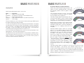
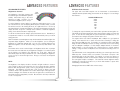
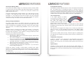
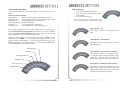
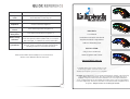
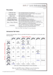
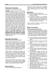
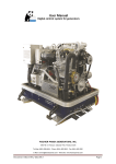
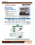
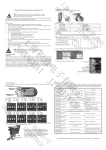
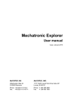
This product may not be suitable or safe for road usage. The owner accepts ALL
responsibility for its use and installation. The product must not be used if malfunction
occurs, a suspected malfunction occurs and/or not configured correctly. If
inappropriately placed, the headlights from another vehicle could cause the
brightness to increase. It must not be used where it could obstruct the view of the
operator or impair the vision. The owner/driver must test before use in all ambient
light conditions to ensure any malfunction or display mode, such as all lights on at
maximum brightness, does not impair the ability to safely operate the vehicle. The
button controls must not be used while operating the vehicle. The product must be
appropriately fused, or connected to an existing appropriately fused circuit. This
product must not be used for medical purposes.
12 month warranty from date of purchase is provided on manufacturing defects,
which is void if the product is opened, disassembled, visibly damaged, or
inappropriately used.
Only use if safe to do so and at your own risk.
INTRODUCTION .......................................................................................................... 3
BASIC FEATURES ...................................................................................................... 4
Calibration Value........................................................................................... 4
Setting Your Shift-Points............................................................................... 5
Display Mode ................................................................................................ 6
Automatic Battery Voltage Indication............................................................ 7
ADVANCED FEATURES............................................................................................. 8
Shift-I™ is a progressive gear shift and RPM range indicator. The seven lights are
used to indicate a section of your RPM, the first light turning on at your programmed
low RPM point, and depending on the display mode, all lights flashing at your
programmed high RPM point.
Typically the low RPM is set where the power starts to kick in, and the high RPM
point is set at the shift point. The example dyno chart below illustrates useful RPM
set-points. Straight line gear shifting can become more consistent, not only from the
flashing display indicating when to shift, but the incremental display allows the driver
to anticipate the shift.
EXAMPLE DYNO CHART
First Light
Shift Point
Brightness Control ........................................................................................ 8
Rpm Set-Point Interval.................................................................................. 9
Cruise Mode Dimming ................................................................................ 11
Over Voltage Alert....................................................................................... 11
POWER hp
Battery Voltage Calibration ......................................................................... 10
TORQUE lb.ft
Running In Battery Mode ............................................................................ 10
Temperature Protection .............................................................................. 11
System Reset.............................................................................................. 11
ADVANCED SETTINGS MENU................................................................................. 12
Startup Display............................................................................................ 13
Cruise Mode Timer ..................................................................................... 14
Rpm Hysteresis........................................................................................... 15
Over Voltage Warning................................................................................. 16
Sensitivity.................................................................................................... 17
QUICK REFERENCE................................................................................................. 18
RPM
Knowing the optimal RPM range can be particularly useful for both circuit and street
driving. It can indicate if your entry RPM is below the start of the power curve, and
also indicates if your RPM is getting too high to accelerate out of the turn.
The Shift-I can be used to optimize launch control by keeping the RPM in the ideal
range. Break out of old habits by setting optimal RPM set-points; form better driving
habits and control.
Why seven lights? In your peripheral vision you can instantly and easily recognize
how many of the seven lights are on. With more lights, concentration is required.
Trials determined seven was the optimal number.
The first light on the left can be easily programmed to turn on at a RPM value you
choose, and so can the last. This ensures your Shift-I™ is customized to your
vehicle and driving style. The lights in-between are automatically set at equal RPM
divisions.
Read this section to find out how to get up and running.
Read the advanced functions when you want to tweak more.
Calibration Value
The RPM signal varies between different manufacturers and models, therefore a
“Calibration Value” setting is provided. Using the correct setting is VERY important,
as many of the functions are dependant on the RPM value. Most functions are
locked out if the RPM is above 2,200!
The easiest way to determine the correct
calibration setting required is simply to just try
it! The unit is delivered with a calibration value
of 2 and set for the lights to turn on at what it
believes is 1,000, 2,000, 3,000 RPM etc… If
you perform a system reset, these default
settings will be restored (page 11).
Start the engine and increase the RPM slowly to check if the first light comes on at
1,000 RPM, the second at 2,000 RPM, third at 3,000 RPM etc. If the first light does
indeed come on at or near 1,000 RPM, then the default calibration value is correct.
If not, use the table below to find the “Calibration Value Required” (typically 0.5, 1, 2
and 4). Please keep in mind that a lot of needle tachos are inaccurate, so 1,000
RPM may be a little higher or lower than you expect.
To set your Shift-I™ to this value, first you need to enter the calibration mode. With
the ignition off, press and hold both buttons, turn the ignition on and then release the
buttons. If it is the first time you have entered this mode, you will see the first two
lights are illuminated indicating the default value of 2. Press up or down to change
the settings, and then press both buttons to save. You can re-enter the calibration
mode to verify your setting if you wish.
1st
Light
4,000
2,000
1,333
1,000
800
667
500
400
333
250
2nd
Light
8,000
4,000
2,667
2,000
1,600
1,333
1,000
800
667
500
3rd
Light
4th
Light
5th
Light
12,000
6,000
4,000
3,000
2,400
2,000
1,500
1,200
1,000
750
16,000
8,000
5,333
4,000
3,200
2,667
2,000
1,600
1,333
1,000
20,000
10,000
6,667
5,000
4,000
3,333
2,500
2,000
1,667
1,250
CALIBRATION
ACTION
DISPLAY AFTER
VALUE
REQUIRED
ACTION
REQUIRED
0.5
Press Down 3 Times
1 Light flashing
1
Press Down 2 Times
1 Light On
1.5
Press Down Once
1 Light On, 1 flashing
2
DEFAULT - No Action
2 Lights On
2.5
Press Up Once
2 Lights On, 1 flashing
3
Press Up 2 Times
3 Lights On
4
Press Up 3 Times
4 Lights On
5
Press Up 4 Times
5 Lights On
6
Press Up 5 Times
6 Lights On
8
Press Up 6 Times
All Lights On
If the lights comes on too soon, then the calibration value must be increased.
If it comes on too late, then it must be decreased.
Setting Your Shift-Points
You can change at what RPM value the
sequence starts and ends to suit your
engine and preference. For example,
setting the lower RPM set-point to 7,000 will
result in the first light turning on at
7,000rpm. Setting the upper RPM set-point
to 13,000rpm will result in the sequence
ending at 13,000rpm. The lights inbetween are evenly spaced between the
lower and upper set-points.
13,000
7,000
10,000
11,000 12,000
9,000
8,000
These set-points can be changed with the engine off, or when the RPM is below
2,200. To enter the mode to set the lower RPM set-point, with ignition turned on,
press and hold the down button. After a couple of seconds, the display will change
as the mode is entered and you can release the button.
The five lights on the left are used to represent the value of the low RPM set-point.
To read the value, just count how many times each light flashes, which represents
the number. For example, a value of 12,500rpm would flash the left most light once,
the next one twice and the third one 5 times.
It may take a little practice to read, however you can easily do this with a couple of
tips. A demonstration of this is available on the website. The light representing units
on the right is always zero, and until you venture into the advanced section, the tens
and hundreds will also be zero. So you only have to count two lights… thousands &
tens of thousands, of which you will probably only see a one or a zero for the first
light, so you only need to really count one light! Much easier than initially expected.
The sequence repeats after a short pause.
You can now press the up or down button to increment or decrement the set-point.
By default, it will step 1,000rpm at a time. Refer to the advanced section “RPM
Threshold Resolution” if you want to change this to a smaller step adjustment.
To set the upper RPM set-point, use the up button instead to enter the mode with
the same method as described above. This time, the five lights on the ‘right’ are
used to represent the set point value.
To exit the mode and save your settings, press both buttons simultaneously.
Alternatively, if the engine is running, you can just blip the revs over 2,200rpm and it
will automatically exit and save for you. If you don’t want to save the changes, just
turn the ignition off before exiting the mode.
Automatic Battery Voltage Indication
Display Mode
Shift-I™ has multiple display modes to choose from.
Mode ................Description
Off.....................Lights do not respond to RPM
Cumulative........The lights turn on and stay on as the RPM increases
Dot ...................Only one light on at a time
Shift Only ..........Lights flash at shift set-point only, made for track racers.
Special..............Just for bling!
There are variations to some of these modes, whereby at the upper RPM set-point
the display will flash the last light or all lights.
You can cycle through these modes by using the up and down buttons. The display
will demonstrate the selected mode with a quick animation, and then automatically
save your selection. If the RPM is above 2,200, any button press will only turn off
the display, or restore the display to the last display mode. You should never
operate this product moving and/or when it is not safe to do so.
If you cycle down to the first display mode, you will see a very quick animation of the
lights turning off. This mode keeps the display off.
The display mode used is personal preference. Some prefer the cumulative modes,
others may find the shift only mode useful. It is recommended to give several of the
modes a serious try, as only with practice will you be able to train yourself to
effectively read and evaluate the display mode.
Shift-I™ also provides a battery voltage indication. This
feature is an aid to evaluating the state of the battery
and detecting problems with the ignitions voltage
regulation.
The seven lights represent 9 to 15 volts. The first light
on the left will turn on when the voltage is 9 or greater,
the second light 10 volts or greater etc…
The battery voltage display will automatically turn on a
short period after ignition is turned on (without starting
the engine). You can identify this mode by the lights
starting quite dim, and then ramping up in brightness.
With the engine off, a battery in good condition and well
charged will typically register ~12.5V. However, this is
dependant on many factors, such as the temperature of
the battery and if it is supplying current (such as to
headlights).
Assuming a battery voltage of 12.5V, four of the lights
will be on. As you start the engine, the starter motor
draws a lot of current from the battery and its voltage
will temporarily drop 1 or 2 volts, which you will see on
the display. If the battery is not in good condition,
and/or low on charge, you will notice when the starter
motor cranks the engine the voltage will drop further.
Once the engine is started, it will typically generate
~13V at idle and up to ~15V at higher RPMs. Typically
you wont see more than 15.5V. Refer to your vehicles
specifications for more accurate expectations. Higher
voltages may indicate a failure of the charging circuit,
and prolonged exposure can cause damage to the
electrics.
10+
11+
12+ 13+ 14+
15+
9+
Voltage Scale
Ignition On
Low Battery
Voltage
Engine
Running
>16V if flashing
The battery voltage display is for general use only, and not to be relied on for fault
detection and diagnosis. The accuracy of the indicated voltage may not be
accurate, and the voltage at Shift-I™ may be different to the voltage at the battery.
Please refer to the advanced section for more detailed information about how this
feature is calibrated. This mode will automatically exit around 3 seconds after an
attempt to start the engine is made, or if a button is pressed.
ADVANCED FEATURES
Brightness Control
The brightness of the lights changes with
the ambient light, which maintains optimum
visibility. When dark, they go dim, when
light they go bright. However, you can
customize how bright they are to suit you.
RPM Set-Point Interval
The upper and lower RPM set-points can be incremented or decremented at
1,000rpm intervals (default setting), however this can be changed. You can change
this interval to…
Light
Sensor
Available RPM Intervals
4,000
2,000
1,000
500
250
100
50
To set the brightness, ensure ignition is on and press both buttons at once. If you
are in another mode, such as adjusting RPM set-points or battery watch, you must
first exit those modes. On entering the mode, all 7 lights will turn on. Use the up
and down buttons to change the brightness. Each time an adjustment is made, the
display will blink, except if it is already at the minimum or maximum brightness
setting. Press and hold a button to adjust quickly.
To change the set-point interval, press and hold the up button and turn ignition on.
The display will show the interval value in the same format as setting your lower shift
point. To save the new setting and exit, press both buttons simultaneously. If you
don’t want to save changes, turn ignition off when safe to do so.
To exit the mode and save the changes, press both buttons at once. Alternatively, if
no adjustment is made for 4 seconds, Shift-I™ will automatically save your current
settings and exit.
For engines with a lower redline <10,000rpm, 250 or 500rpm is a good practical
setting. If the interval is set too small, it becomes time consuming to change the
upper and lower RPM set-points. For example, for commuting you may set the RPM
range at 1,500 to 5,500rpm, however for racing on the track a more useful setting
may be 3,500rpm to 6,250rpm. For this example, 250rpm intervals is convenient,
50rpm intervals is over kill requiring lots of button presses to change between
settings. Using an interval of 50rpm becomes useful when fine tuning of the setpoints.
Shift-I™ maintains a smart brightness map, which translates the ambient light to the
requested display brightness. When you set the brightness, you are setting the
brightness for a particular ambient light. So if the sun is shining bright and you
adjust the brightness, it won’t affect the setting you previously made when it was
darker.
This feature can be used to set the display to full brightness all the time, or perhaps
the lowest level in the dark and only ½ brightness at daylight. You cannot however
set the display to be brighter in the dark than it is in the light. Shift-I™ will
automatically adjust the map to maintain this rule. When adjusting the brightness,
do not cover up or obscure the light sensor. Doing so could cause an unexpected
adjustment.
The RPM interval can be changed without affecting your current upper and lower
RPM set-points. However, when you increment or decrement a set-point, it will
automatically align to the next multiple. For example, if you have your upper setpoint at 10,250rpm, and then set the interval to 100rpm, the next increment will go
the next highest multiple, 10,300rpm. This automatic interval alignment makes
changing the set-point much easier, as you know what number to expect while
incrementing or decrementing.
NOTE:
The brightness of the display should be checked in all light conditions to ensure it
does not blind or obscure your view before use. Do not expect the unit to transition
between dark and light areas quickly, such as going through an unlit tunnel on a
bright day. The brightness level will take a few seconds to adjust to the light
conditions, which is also dependant on its location and the light on the light sensor.
Vehicles headlights from behind can also trick the light sensor, and therefore its
placement should be appropriately selected. Disconnect the unit if any malfunction
occurs or is suspected.
Changing the interval does NOT effect on the accuracy.
!
"
Running In Battery Mode
Cruise Mode Dimming
This mode provides battery voltage to be continuously monitored, instead of RPM.
To enter this mode, press and hold the down button and turn ignition on (remember
B=Battery=Bottom/Down Button). To exit the mode, either press a button or turn
ignition off when safe to do so.
If the RPM has remained relatively steady for 1 minute, the display will automatically
dim. The primary reason for including this feature is to prevent becoming too
accustomed to the lights (being desensitized) during periods of cruising. When this
activates, the display will slowly dim and you may not even notice it has happened.
It will stay dim even with slow changes in RPM. However, when a significant change
in RPM is detected, the display will immediately return to the original brightness.
As with the “Automatic Battery Voltage Indication”, the 7 lights represent 9 to 15V.
In addition, if the voltage goes above 16V the light on the far right will flash
immediately, or if the voltage goes below 9V, the light on the far left will flash
immediately. This mode may be useful to see how the charging and regulation
circuitry is functioning. This feature can assist with fault detection.
Over Voltage Alert
If the voltage registered at Shift-I™
exceeds 16V for more than 3 seconds, an
over voltage warning is displayed. When
this occurs, the display mode is
Over voltage alert!
overridden, and the two lights on the far
right are flashed. This will still occur if the
display is in the off mode. After 1 minute, this warning light will continue although
the brightness will automatically dim. Normal operation is restored if the voltage falls
back below 16V.
Battery Voltage Calibration
The ignition voltage supplied to the Shift-I™ unit may be lower than the actual
voltage at the battery. This is often the case when the same ignition circuit also
powers something like the headlights, where large currents cause larger voltage
drops in the wires. The “Battery Voltage Calibration” can be used to offset the
difference.
This feature will not be triggered if the voltage does not continuously remain above
16V for 3 seconds. It is also dependant on the accuracy of the “Battery Voltage
Calibration”. To detect intermittent voltage fluctuations, use the “Running in Battery
Mode”.
Calibration allows for correcting up to ±2.00V, in 0.1V intervals. To perform the
calibration, you will need a voltage meter. With ignition on, measure the voltage at
the battery and at the Shift-I™. As an example, you may get 12.54V and 12.12V
respectively. This example has a 0.42V drop.
If this alert does activate, treat it seriously. When the ignition is operating above
16V, light bulbs will eventually fail, the battery will boil and there is additional risk to
all electronics.
Use the following method to adjust the calibration..
1. Enter Running in Battery Mode described above (press & hold the down
button and turn ignition on).
2. First, reset the calibration to zero by pressing and holding both buttons
until you see a quick flash of the lights, then release.
3. To add a 0.1V offset, press & hold the up button until you see a quick flash
of the lights, then release. To subtract 0.1V, use the down button instead.
4. Repeat step 3 until the desired offset is reached. In the previous example,
with a 0.42V drop you would add four 0.1V offsets.
5. To save the results, press and release either button. If you don’t want to
save the setting, turn ignition off.
Temperature Protection
If Shift-I™ is operated in a hot environment, it will automatically protect itself by
dimming the display. It will automatically re-enable when the temperature is
reduced. This is for protection only, and under normal operation this would never be
observed.
System Reset
Performing a system reset will safely restore ALL factory default settings. To
perform the reset, turn ignition off, press and keep held both buttons, turn ignition on
and around four seconds later a rapid flashing sequence will acknowledge the reset
is complete.
Verifying the setting is accurate is difficult without a variable power supply.
However, you may find as the RPM is increased from idle the voltage will increase,
which you can compare when each light turns on to the corresponding reading from
the voltage meter.
Incorrect adjustment could result in the over voltage warning being triggered falsely.
#
Advanced Settings Menu
Startup Display
The advanced settings have been made available for those feeling the need to
tweak!
There are 6 advanced settings.
Startup Display .............. Determine what is displayed when ignition is turned on.
Cruise Mode Timer ........ Change the time it takes before the lights dim while cruising
RPM Hysteresis............. Set the RPM gap before the lights turn off.
Over-Voltage Warning ... Enable/Disable/Adjust.
Sensitivity....................... Used to eliminate any display flicker.
RPM Input Delay............ Ignore RPM input for set time after ignition on.
These settings are organized in a menu. Accessing the menu is a two step process.
First, hold both buttons and turn ignition on, which will get you into the calibration
menu. Now press and hold the UP button, and after a couple of seconds the first
light will rapidly flash. This is the advanced settings menu.
The menu is better understood by considering the UP button as “NEXT”, and the
DOWN button as “ENTER”. The first light rapidly flashing indicates the first
advanced setting, “Startup Display”. If you pressed the UP button, you’ll go to the
NEXT item in the menu, “Cruise Mode Timer”. If you pressed the DOWN button,
you would ENTER the current advanced setting.
1. Press both buttons and turn ignition on.
2. Press and hold up button until first light
flashes rapidly.
3. Press the down button once.
Press the up button to cycle through the
options, and press down to select the one you want.
Startup Display = Off
When ignition is turned on, the display will stay
blank.
Startup Display = Shift Sequence
When ignition is turned on, the display will show the
shift light sequence.
RPM Input Delay
Sensitivity
Over-Voltage Warning
RPM Hysteresis
Cruise Mode Timer
Startup Display
Startup Display = Shift Sequence then Battery
When ignition is turned on, the display will show
the shift light sequence, then show battery voltage
shortly after. When the engine first cranks, the
battery voltage display will turn off 3 seconds later.
Startup Display = Battery then Shift Sequence
When ignition is turned on, the display will show the
battery voltage. When the engine first cranks, the
battery voltage display will turn off 3 seconds later
and then show the RPM shift sequence.
Cruise Mode Timer
RPM Hysteresis
Cruise mode is an automatic feature that dims the display if the RPM has remained
relatively steady for a period. This setting lets you adjust how long it takes before
cruise mode activates. Refer to the user guide for more information.
RPM hysteresis prevents flickering when the RPM is hovering around the turn on
point for a light. For example, if the first light is programmed to turn on a 3,000rpm
and the engine RPM is fluttering around that same point, then normally the light
would flicker. With RPM hysteresis, it might take 3,000rpm to turn the light on, but it
won’t turn off until the RPM drops a bit more, for example 2,750rpm.
1. Press both buttons and turn ignition on.
2. Press and hold the up button until first
light flashes rapidly.
3. Press the up button once, and the second
light should be flashing
4. Press the down button once.
Press the up button to cycle through the options, and press down to select the one
you want.
Cruise Mode =30 Seconds
If the RPM is steady for 30 seconds, the display
will dim.
Cruise Mode =45 Seconds
1. Press both buttons and turn ignition on.
2. Press and hold up button until first light
flashes rapidly.
3. Press the up button twice, and the third
light should be flashing
4. Press the down button once.
Press the up button to cycle through the options,
and press down to select the one you want.
RPM Hysteresis = Off
RPM Hysteresis = 6.25%
For example, first light turns on at 1,000rpm,
second light turns on at 2,000rpm, then the
second light will turn off at 1937.5rpm
RPM Hysteresis = 12.5%
Cruise Mode =60 Seconds
RPM Hysteresis = 25%
Cruise Mode =90 Seconds
RPM Hysteresis = 50%
Cruise Mode =120 Seconds
RPM Hysteresis = Auto (default)
350rpm or 25%, whichever is smaller.
Over Voltage Warning
Sensitivity
If the voltage exceeds 16V for more than 3 seconds, the over voltage warning will
override the display. This setting allows you to change the voltage alert value, or
disable the feature. Refer to the user guide for more information about this feature.
Different makes/models have different tacho signals. If you experience display
flickering or the high RPM range isn’t working properly, then this setting should be
adjusted.
1. Press both buttons and turn ignition on.
2. Press and hold up button until first light
flashes rapidly.
3. Press the up button three times, and the
fourth light should be flashing
4. Press the down button once.
Press the up button to cycle through the options, and press down to select the one
you want.
1. Press both buttons and turn ignition on.
2. Press and hold the up button until first
light flashes rapidly.
3. Press the up button four times, and the
fifth light should be flashing
4. Press the down button once.
Press the up button to cycle through the options, and press down to select the one
you want.
There are seven sensitivity setting, from minimum to maximum.
Over Voltage Warning = Off
Sensitivity = Minimum
Reduce the sensitivity if the display flickers.
Over Voltage Warning when > 15.5V
Sensitivity = Maximum
Over Voltage Warning when > 16.0V (default)
Increase the sensitivity if the RPM is not being
detected properly, typically at high RPMs.
The default setting is 6, and is appropriate for almost all cases.
Over Voltage Warning when > 16.5V
Older cars…
If connecting on the low side of the coil, then often a setting of 3 or 4 is perfect.
Some aftermarket tachos also introduce additional inductive noise on the tacho
signal, which these settings will filter out.
Older bikes…
Although infrequent, small capacity engines with high redlines can take advantage of
the highest sensitivity setting.
Calibration Value
Press and hold both buttons, turn ignition on.
Setting Shift
Points
Press and hold up button for upper set-point. Press and hold
the down button for lower set-point
Display Mode
Press up or down to cycle through modes
Brightness
Adjustment
Press both buttons (all lights turn on), then use buttons to
increase or decrease brightness.
RPM Set-Point
Interval
Press and hold up button, turn ignition on.
Running in
Battery Mode
Press and hold down button, turn ignition on.
Battery Voltage
Calibration
Press and hold the down button, turn ignition on. To add a
0.1V offset, press & hold the up button until you see a quick
flash of the lights. To subtract 0.1V, use the down button.
Installation and Quick Start Guide
Adhesive Mounting Pads
System Reset
Press and hold both buttons, turn ignition on (keeping buttons
pressed). A few seconds later, the lights will flash rapidly
indicating reset and you can release the buttons.
INCLUDES:
User Manual
Vinyl Backed Shift-I Logo Sticker.
INSTALLATION:
Refer to the “Shift-I User Manual” for more information.
Only 3 wires to connect.
Ground, Ignition and Tacho!
Make sure the RPM is below 2,200rpm to access the functions,
and the correct calibration value has been used.
www.ecliptech.com.au
Compatible with 4-stroke engines and those using
transistor type ignition. Some two strokes and
distributed point ignition systems are not compatible.
Disclaimer: By using this product, you accept the following terms & conditions. This product may
not be suitable or safe for road usage. The owner accepts ALL responsibility for its use &
installation. The product must not be used if malfunction occurs or a suspected malfunction
occurs. If inappropriately placed, the headlights from another vehicle could cause the brightness
to increase unexpectedly. It must not be used where it could obstruct, hinder or impair the view of
the operator. Only use if safe to do so and at your own risk.
!