1
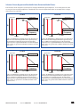
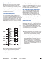
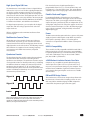
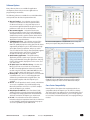
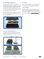
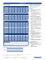
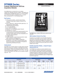
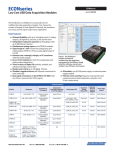
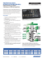
Simultaneous Series DT9832 and DT9836 Modules DT9832 and DT9836 Series Simultaneous USB DAQ Modules High Performance, Isolated Simultaneous USB Data Acquisition The Simultaneous Series is a family of high-performance, multifunction data acquisition (DAQ) modules for the USB bus. The series features simultaneous analog inputs, deglitched waveform analog outputs, 32 digital input/output lines, 2 counter/timers, and 3 quadrature decoders. All subsystems can be run synchronously. Key Features: ■ ■ ■ ■ ■ ■ ■ ■ ■ ■ ■ ■ ■ ■ ■ ■ Simultaneous operation of analog input, analog output, digital I/O, and counter/timer subsystems 16-bit resolution Throughput rate up to 2 MSamples/s 2, 4, 6, or 12 single-ended channels depending on the model selected Input ranges of ±10 and ±5 V 32 digital I/O lines Two 32-bit counters(C/T) channels that perform event counting, up/down counting, frequency measurement, edge-to-edge measurement, continuous pulse output, one-shot, and repetitive one-shot operations Three 32-bit quadrature decoders that can provide relative or absolute position of quadrature encoder input and calculate rotational speed Synchronize digital, counter, and quadrature decoder inputs with the analog measurements 0, 2, or 4 16-bit D/A channels, depending on the model selected, with output rate up to 500 kSamples/s− Output range of ±10 V DACs are deglitched to prevent noise from interfering with the output signal Continuous output mode or waveform generation mode External or internal clock source Trigger operations using a software command, an analog threshold value, or an external digital trigger ±500 V galvanic isolation barrier that prevents ground loops to maximize analog signal integrity and protect your computer Available either installed in a metal BNC connection box, or as a board-level OEM version that you can install in your own custom application Figure 1. The DT9836S, shown in BNC connection box, provides simultaneous analog inputs at up to 800 kHz per channel. USB 500V Isolation Barrier Simultaneous A/D up to 2.0MHz per channel Analog In 16-bit A/D 16-bit A/D 16-bit A/D 2, 4, 6 or 12 Simultaneous Channels Analog In Analog Out Up to 4 Output Clock Up to 500kHz 16-bit A/D 16 DO DOUT DIN 16 DI Software Triggers C/T 2, 32-bit Up to 48 MHz QD 3 Quadrature Encoders Ext Clocks Clock & Trigger Control Ext Triggers Input Clock Up to 2.0MHz Figure 2. The DT9836 and DT9832 Series provides USB 2.0 multifunction modules for simultaneous acquisition of 2 to 12 analog inputs. Each series differs only in the number of simultaneous inputs and the throughput speed. All functions: A/D, D/A, DIO, Quad Decoder, and C/T can be synchronously triggered. Features Summary Analog Inputs Resolution Input Range Sample Rate Digital I/O C/Ts Quadrature Decoders Analog Outputs Isolation DT9832 Series 2 or 4 SE 16-bit ±10V Up to 2 MHz/ch 16 in, 16 out 2 3 0 or 2 ±500 V DT9836 Series 6 or 12 SE 16-bit ±5V, ±10V Up to 800 kHz/ch 16 in, 16 out 2 3 0, 2, or 4 ±500 V Model www.datatranslation.com US/Canada (800) 525-8528 Europe/Asia +49 (0) 7142-9531–0 Simultaneous, High Accuracy Performance The High Performance Simultaneous Series provides simultaneous analog input operation. Each analog input has its own A/D converter to eliminate phase shift between channels ‒a problem with multiplexed architectures where all inputs share one A/D converter. As a result, this Series allows you to correlate simultaneous measurements. Precision Measurements... True 16-bit A/D at up to 2.0MHz throughput per channel for measuring multiple input signals simultaneously Simultaneous Analog Inputs... 2, 4, 6 or 12 simultaneously sampled analog input channels www.datatranslation.com No Limits... Full simultaneous and synchronous operation of all subsystems. Designed for Low Noise... 12-layer PCB provides optimal grounding and shielding to maintain signal integrity Fully Protected... ±500V galvanic isolation protects your computer and maintains signal integrity Ultra Digital I/O... Three Quadrature Full digital I/O Decoders... For flexibility for time X/Y positioning and stamping, pattern rotation (tachos) recognition, and synchronizing with Full-featured Flexible external events Counter/Timers... Two 32-bit counter/timers ideal for testing applications. US/Canada (800) 525-8528 Europe/Asia +49 (0) 7142-9531–0 External Control... Flexible clocks and triggers High-Speed USB 2.0... USB 2.0 connector for data transfer at up to 480Mbps Flexible Power Connections... +5 V connector; a secondary +5 V connector is provided for embedded applications 2 Selection Criteria: Nyquist and Bandwidth Limits Determine Model Choices Each model has been designed to accurately measure higher bandwidth signal components. To accurately measure 16-bit accuracy, the front-end input amplifier has a bandwidth of ten times the Nyquist limit. Below are examples of these design characteristics for each board. DT9832 DT9832A Nyquist Limit Nyquist Limit Sampling Rate Sampling Rate 3 dB Point 3 dB Point dB dB 625kHz 1.25MHz Signal Bandwidth Signal Bandwidth Frequency Frequency 1.0MHz >6.25MHz 2.0MHz >10.0MHz Figure 3. The DT9832 has a sampling rate for each channel of 1.25 MHz. This means that the Nyquist limit allows signal frequencies up to 625 kHz to be adequately measured. The analog input components have a signal bandwidth that is ten times the Nyquist limit or in this case, greater than 6.25 MHz to minimize roll-off and phase errors. Figure 4. The DT9832A has a sampling rate for each channel of 2.0 MHz. This means that the Nyquist limit allows signal frequencies up to 1.0 MHz to be adequately measured. The analog input components have a signal bandwidth that is ten times the Nyquist limit or in this case, greater than 10.0 MHz to minimize roll-off and phase errors. DT9836 DT9836S Nyquist Limit Nyquist Limit Sampling Rate 3 dB Point Sampling Rate 3 dB Point dB dB 112.5kHz 225kHz Signal Bandwidth Signal Bandwidth Frequency Frequency 400kHz >1.125MHz Figure 5. The DT9836 has a sampling rate for each channel of 225 kHz. This means that the Nyquist limit allows signal frequencies up to 112.5 kHz to be adequately measured. The analog input components have a signal bandwidth that is ten times the Nyquist limit or in this case, greater than 1.125 MHz to minimize roll-off and phase errors. www.datatranslation.com US/Canada (800) 525-8528 800kHz >4.0MHz Figure 6. The DT9836S has a sampling rate for each channel of 800 kHz. This means that the Nyquist limit allows signal frequencies up to 400 kHz to be adequately measured. The analog input components have a signal bandwidth that is ten times the Nyquist limit or in this case, greater than 4.0 MHz to minimize roll-off and phase errors. Europe/Asia +49 (0) 7142-9531–0 3 Figure 7. These graphs show the outstanding quality of the DT9832 Series and DT9836 Series for all error sources... with ENOB (Effective Number Of Bits) ratings of 13.6, 13.6, and 14.1 bits respectively and an SFDR (Spurious Free Dynamic Range) of 86dB to 95dB. www.datatranslation.com US/Canada (800) 525-8528 Europe/Asia +49 (0) 7142-9531–0 4 Synchronous Operation All functions of the data acquisition modules (All A/D, D/A, DIO, Counter Timers, and Quadrature Decoders) can be simultaneously triggered internally or externally. The data can then be streamed synchronously to host memory. This can be done via external trigger or by the internal clock of the module. The synchronous operation allows all I/O data to be processed and correlated for all inputs and outputs. This is very valuable in determining the response across a device-under-test (DUT) to stimuli at the same exact instant. Closely Matched Analog Inputs The isolated analog inputs of the simultaneous series have been designed to match each other with high precision. Each input has its own separate high impedance 16-bit A/D converter. The impedance has been carefully matched for each of the inputs so that one looks exactly like the other. The data acquisition board has 12-layers in its make-up to adequately shield and protect each signal path etch from the high speed transitions of the digital lines. The slightest mismatch would result in DC and AC errors in measurement when trying to correlate readings at the same instant in time. The SFDR plot in Figure 6 gives the best indication of the match of these DC and AC characteristics. The AC dynamic performance at high switching speeds for all channels shows overall accuracy to be better than 13.6 bits. This is worst case with all errors shown in the FFT ENOB plot. This performance is beyond any other data acquisition system available. High-Speed, High-Resolution Analog Outputs There are 2 simultaneous 16-bit analog outputs, and an option for 4, on the DT9836 Series, comprising separate high speed, deglitched, waveform D/A converters. This design allows highly accurate arbitrary waveforms to be generated at throughput speeds of 500 kHz each. Standard waveforms such as sine, triangle, and square waves are easily produced by loading the output memory and triggering them synchronously or separately. Great care has been used in design to minimize the glitch energy for any major or minor carry. This results in extremely smooth waveforms. Flexible Output Modes Using the Simultaneous Series, you can output a single value from a single analog output channel or multiple values from multiple analog output channels. An output channel list gives you the flexibility of updating only the analog output channels you want or updating the digital output lines with specified analog output channels at the D/A clock rate. You can update analog output channels at up to 500 kSamples/s. Both Series feature the following output modes: ■ ■ Continuous output mode ‒ Choose this mode if you want to accurately control the period between conversions of individual output channels in the output channel list. Waveform mode ‒ Use this mode if you want to output waveforms repetitively from an output FIFO on the module, minimizing communication overhead with the host computer. If you specify only one channel in the output-channel list, you can load a waveform containing up to 128 kSamples into the output FIFO. If you specify all the analog output channels and the digital output lines in the output-channel list, you can load a waveform containing up to 24 kSamples into the output FIFO. Using waveform mode, you can update multiple channels at up to 500 kSamples/s. Figure 8. The DT9836 Series features 6 or 12 independent, successiveapproximation A/D converters with track-and-hold circuitry. Each converter uses a common clock and trigger for simultaneous sampling of all analog inputs at up to 225kS/s per channel. The DT9832 Series features 2 or 4 simultaneous A/D converters with sampling rates up to 2.0 MHz. www.datatranslation.com US/Canada (800) 525-8528 Europe/Asia +49 (0) 7142-9531–0 5 High-Speed Digital I/O Lines The Simultaneous Series modules feature 32 digital I/O lines dedicated as 16 in or 16 out. The first eight digital input lines can also be used for interrupt on change. You can read all the digital input lines simultaneously with the analog input channels at the A/D clock rate. The digital input lines can also be clocked separately as the only channel in the channel-gain list at up to 225 kHz on the DT9836, 800 kHz on the DT9836S, 1.25 MHz on the DT9832, and 2.0 MHz on the DT9832A. For digital output operations, you can update all the digital output lines with the analog output channels at the D/A output clock rate. All lines are EMI protected to minimize interference from transient signals. Multifunction Counter/Timers All Simultaneous Series modules feature two 32-bit user counter/timers. If you wish, you can read the value of the counter/timer channels with the analog input channels and digital input lines at the A/D clock rate. The following counter/ timer functions are supported: event counting, frequency measurement, pulse width measurement, and period measurement. Quadrature Decoder The Quadrature Decoder module contains three quadrature decoders which allow simultaneous decoding of three quadrature encoded inputs. The quadrature decoders may be used to provide relative or absolute position or, by calculating the difference between samples, the rotational speed. Each quadrature decoder supports “A”, “B”, and “Index” inputs. The index input may be used to zero out the positional count and the A and B input relationships are used to increment or decrement the positional count. Each decoder features a digital input filter that is programmable from 27ns to 7μs for the DT9836 Series and from 20ns to 5μs for the DT9832 Series. This unique filtering capability helps remove ringing edges and unwanted noise. Flexible Clocks and Triggers For maximum flexibility, all Simultaneous Series modules provide independent clocks and triggers for the A/D and D/A subsystems. This allows you to trigger and clock the analog output subsystem synchronously with, or independent of, the analog input subsystem. Each subsystem supports an internal clock and external clock input, as well as the following trigger types: software command, analog threshold, and external digital input trigger. Power The BNC connection box option includes a separate +5V power supply and power cable for quick setup. OEMs can purchase these options separately as EP361. A secondary power connector is also provided for OEMs to allow custom power wiring. USB 2.0 Compatibility These modules are fully compatible with USB 2.0 and USB 1.1. USB 2.0 extends the speed of connection to up to 480 Mbps. For optimal performance, it is recommended that you use the series with a USB 2.0 port. They can be used with a USB 1.1 port, but at USB 1.1 performance. ±500V Galvanic Isolation Protects Your Data Computers are susceptible to ground-spikes through any external port. These spikes can cause system crashes and may even cause permanent damage to your computer. These modules feature ±500 Volts of galvanic isolation to protect your computer from ground-spikes and to ensure a reliable stream of data. EMI and ESD Design Criteria The simultaneous series has been designed to perform with the lowest noise characteristics. Damping resistors in series with every I/O line minimize ringing and EMI and provide current limits that protect against transient signals. Figure 9. A quadrature decoder takes the output signals (A, B, and Index) for the quadrature encoder as inputs and converts these signals into a numerical value that can be used to determine position, distance, velocity, and other functions. www.datatranslation.com US/Canada (800) 525-8528 Europe/Asia +49 (0) 7142-9531–0 6 Software Options Many software choices are available for application development, from ready-to-measure applications to programming environments. The following software is available for use with USB modules and is provided on the Data Acquisition Omni CD: ■ ■ ■ ■ ■ ■ ■ ■ ■ Measure Foundry® – An evaluation version of this software is included on the Data Acquisition Omni CD. Measure Foundry® is a drag-and-drop test and measurement application builder designed to give top performance with ease-of-use development. Measurement Applets – Included in the Measure Foundry evaluation version. These small applications, developed with Measure Foundry, can be modified or combined to provide a specific solution. Order the full development version of Measure Foundry to develop applications using real hardware. quickDAQ application – An evaluation version of this .NET application is included on the Data Acquisition Omni CD. quickDAQ acquires analog data from all devices supported by DT-Open Layers for .NET software at high speed, plots it during acquisition, analyzes it, and/or saves it to disk for later analysis. Note: quickDAQ supports analog input functions only. DT9817 and DT9835 modules are DIO only and are not supported. Quick DataAcq application – The Quick DataAcq application provides a quick way to get up and running using your USB module. Using this application, verify key features of the module, display data on the screen, and save data to disk. DT-Open Layers® for .NET Class Library – Use this class library if you want to use Visual C#® or Visual Basic® for .NET to develop application software for your USB module using Visual Studio® 2003/2005/2008; the class library complies with the DT-Open Layers standard. DataAcq SDK – Use the Data Acq SDK to use Visual Studio 6.0 and Microsoft® C or C++ to develop application software for your USB module using Windows®; the DataAcq SDK complies with the DT-Open Layers standard. DTx-EZ – DTx-EZ provides ActiveX® controls, which allows access to the capabilities of your USB module using Microsoft Visual Basic or Visual C++®; DTx-EZ complies with the DT-Open Layers standard. DAQ Adaptor for MATLAB – Data Translation’s DAQ Adaptor provides an interface between the MATLAB® Data Acquisition (DAQ) toolbox from The MathWorks™ and Data Translation’s DT-Open Layers architecture. LV-Link – An evaluation version of this software is included on the Data Acquisition Omni CD. Use LV-Link to use the LabVIEW™ graphical programming language to access the capabilities of your USB module. www.datatranslation.com US/Canada (800) 525-8528 The data recorder applet is developed with Measure Foundry and allows you to acquire data, plot it, and save it to disk. quickDAQ acquires analog data from all devices supported by DT-Open Layers for .NET software at high speed, plots it during acquisition, analyzes it, and/or saves it to disk for later analysis. Cross-Series Compatibility Virtually all Data Translation data acquisition modules are compatible with the DT-Open Layers for .NET Class Library. This means that if your application was developed with one of Data Translationʼs software products, you can easily upgrade to a new Data Translation board. Little or no reprogramming is needed. Europe/Asia +49 (0) 7142-9531–0 7 Flexible Packaging Configurations User Manual The Simultaneous Series modules are available in two packaging configurations: a BNC connection box and an OEM embedded version. The BNC configurations are enclosed in metal boxes with standard BNC and DSUB connectors, 2 BNCs for connecting analog outputs, and 4 BNCs for connecting external clocks and triggers. The BNC configuration ships with a +5 V galvanically isolated power supply and power cable, USB 2.0 cable, and Data Acquisition OMNI CD. Each data acquisition module includes a comprehensive user’s manual. Manuals are provided in electronic (PDF) format on the Data Acquisition Omni CD provided with the module. The OEM configuration, ideal for embedding in test systems, provides all the functionality of the Simultaneous Series in PCboard form. This configuration ships with a USB 2.0 cable and Data Acquisition OMNI CD. Technical Support Application engineers are available during normal business hours to discuss your application requirements. Extensive product information, including drivers, example code, pinouts, a searchable Knowledge Base, and much more, is available 24 hours a day on our web site at www.datatranslation.com. You can also request complimentary support via email or fax at any time. Figure 1. The BNC connection box packages the OEM embedded versions of the board in a CE-compliant enclosure. Accessories for OEM Configurations For applications where you want to embed a DT9832 Series or DT9836 Series module inside other equipment, use the OEM packaging configuration (no enclosure) and our optional accessories. STP37 EP333 EP353 www.datatranslation.com EP356 US/Canada (800) 525-8528 Europe/Asia +49 (0) 7142-9531–0 8 Ordering Summary Data Acqusition Modules: DT9832 Analog In Analog Out Throughput Digital In / Out C/T Q/D Package DT9832-04-0-BNC 4SE 0 1.25 MHz 16 / 16 2 3 BNC DT9832-04-0-OEM 4SE 0 1.25 MHz 16 / 16 2 3 OEM DT9832-04-2-BNC 4SE 2 1.25 MHz 16 / 16 2 3 BNC OEM Model DT9832-04-2-OEM 4SE 2 1.25 MHz 16 / 16 2 3 Analog In Analog Out Throughput Digital In / Out C/T Q/D Package 2SE 0 2.0 MHz 16 / 16 2 3 BNC OEM DT9832A Model DT9832A-02-0-BNC DT9832A-02-0-OEM 2SE 0 2.0 MHz 16 / 16 2 3 DT9832A-02-2-BNC 2SE 2 2.0 MHz 16 / 16 2 3 BNC DT9832A-02-2-OEM 2SE 2 2.0 MHz 16 / 16 2 3 OEM Analog In Analog Out Throughput Digital In / Out C/T Q/D Package DT9836-06-0-BNC 6SE 0 225 kHz 16 / 16 2 3 BNC DT9836-06-0-OEM 6SE 0 225 kHz 16 / 16 2 3 OEM DT9836-06-2-BNC 6SE 2 225 kHz 16 / 16 2 3 BNC DT9836-06-2-OEM 6SE 2 225 kHz 16 / 16 2 3 OEM DT9836-06-4-OEM 6SE 4 225 kHz 16 / 16 2 3 OEM DT9836-12-0-BNC 12SE 0 225 kHz 16 / 16 2 3 BNC DT9836-12-0-OEM 12SE 0 225 kHz 16 / 16 2 3 OEM DT9836-12-2-BNC 12SE 2 225 kHz 16 / 16 2 3 BNC DT9836-12-2-OEM 12SE 2 225 kHz 16 / 16 2 3 OEM Analog In Analog Out Throughput Digital In / Out C/T Q/D Package DT9836S-06-0-BNC 6SE 0 800 kHz 16 / 16 2 3 BNC DT9836S-06-0-OEM 6SE 0 800 kHz 16 / 16 2 3 OEM DT9836S-06-2-BNC 6SE 2 800 kHz 16 / 16 2 3 BNC DT9836S-06-2-OEM 6SE 2 800 kHz 16 / 16 2 3 OEM DT9836 Model DT9836S Model Packaging Configurations: OEM — Board-level embedded version for maximum flexibility. Power supply not included. BNC — Metal box enclosure with BNCs for analog inputs. If you select a model with analog outputs, BNCs are provided. The BNC box configuration also provides 4 BNCs for connecting external clocks and triggers. Power supply and cable included. For more information about the DT9832 Series, including specifications, please visit: http://www.datatranslation.com/info/DT9832Series/ All Data Translation hardware products are covered by a 1-year warranty. For pricing information, please visit our website or contact your local reseller. Accessories ■ EP333 – Cable with two 37-pin male DSUB connectors between STP37 and EP356 or BNC box. ■ EP353 – Accessory panel with 1, 37-pin DSUB connector and 1, 26-pin signal conditioning connector for attaching analog input signals (for OEM configurations only). ■ EP355 – Screw terminal panel for attaching analog I/O and digital I/O signals (for OEM configurations only). ■ EP356 – Accessory panel with 2, 37-pin DSUB connectors for attaching analog output, counter/timer, trigger, clock signals, and digital I/O signals (for OEM configurations only). ■ EP360 – Cable with one 37-pin female and one 37-pin male DSUB connector between STP37 and EP353 or BNC box. ■ EP361 – A +5 V power supply (included with BNC configurations). ■ STP37 – 37-pin screw terminal panel that connects to the EP356, EP353, or BNC box via an EP333 or EP360 cable. Software The following software is available for purchase separately: ■ Measure Foundry (SP1300-CD) – Test and measurement application builder for Windows® XP, Vista, Windows 7. ■ quickDAQ (SP8501-CD) – Highperformance, ready-to-run application that lets you acquire, plot, analyze, and save data to disk at up to 2 MHz per channel. ■ LV-Link – Access the power of Data Translation boards through LabVIEW™. Free Software Downloads The following software is available for free download from our website: ■ DAQ Adaptor for MATLAB – Access the analyzation and visualization tools of MATLAB®. ■ Measurement Applets For more information about the DT9836 Series, including specifications, please visit: http://www.datatranslation.com/info/DT9836Series/ Copyright © 2010 Data Translation, Inc. All rights reserved. All trademarks are the property of their respective holders. Prices, availability, and specifications are subject to change without notice. www.datatranslation.com US/Canada (800) 525-8528 Europe/Asia +49 (0) 7142-9531–0