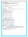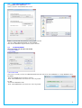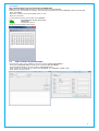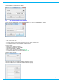
1
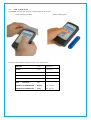
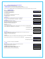
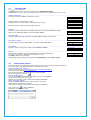
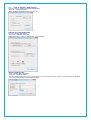
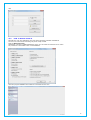
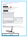
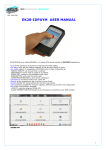
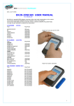
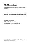
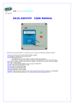
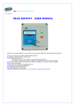
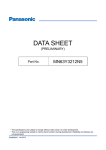
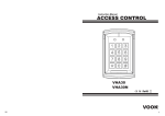
RFID TRANSPONDER TECHNOLOGY
DOC. 337-R1-EN
EK20-IDTRCM
USER MANUAL
EK20-IDTRCM (here named READER) is a mobile device for Traceability applications.
Features:
- Operates with one-two-three frequencies (LF-HF-UHF) as your choice.
- Operates with the most popular TAGs:
LF:Unique, Q5, T5577, Hitag, Titan
HF:Mifare, Icode, Srix UHF: EPC-Gen2, 18000-6C
- Read one or two different TAG in any read cycle.
- Operates with 4 keys only. More easy to use and less error chances.
- Records all the operation LOGs.
- Can create an User Database using our IDONE-R software.
- Program a Text into writeable TAGs.
- Connectable via USB.
- Connectable wireless by RADIO UHF (Standard) or BLUETOOTH.
- Connectable to INTERNET CLOUD by our Microserver.
- Configurable for different Traceability applications.
- LIPO battery rechargeable by USB 5VDC.
- Complete of the IDONE-R program freely downloadable from:
www.zetanetweb.com/download/zetanet.htm
- Compatible with our mobile readers IDGIANO, IDJ3 anf fixed IDTRCF.
“IDTRCM powerful, easy, compact”
1
“IDONE-R”
“IDONE-R” REDUCED
INDEX
1.0
2.0
2.1
2.2
3.0
4.0
4.1
4.2
5.0
6.0
7.0
8.0
9.0
10.0
11.0
12.0
13.0
14.0
HOW TO READ A TAG
HOW TO OPERATE WITH THE READER
WORKING AREA
SETTINGS AREA
IDONE-R FIRST INSTALL
HOW TO CREATE A NEW PROJECT
CONFIGURATION SETTINGS
HOW TO OPEN AN EXISTING PROJECT
LOG MANAGEMENT
HOW TO CREATE AN USER DATABASE
SET CURRENT DATE ON A READER
SET A DEVICE NUMBER ON A READER
PROGRAMMING A TEXT ON TAG
HOW TO REDUCE IDONE-R
BATTERY
AVAILABLE MODELS
TECHNICAL SPEC
HOW TO UPGRADE THE FIRMWARE AND THE LANGUAGE ON THE READER
2
1.0
HOW TO READ A TAG
The READER exec two scan cycles for an easy positioning of the TAG.
Front reading (LF-HF-UHF)
Bottom reading (UHF)
The tipical reading distance depends from the TAG type and size.
UNIQUE
Card
Tip 30 mm
HITAG
Card
Tip 30 mm
MIFARE ISO144443A
Card
Tip 20 mm
ICODE
ISO 15693
Card
Tip 40 mm
SRIX
ISO14443B
Card
Tip 30 mm
UHF
EPC GEN2
Card
VERTICAL POLARIZATION
Bottom
Tip. .160 mm
VERTICAL POLARIZATION
Front
Tip.
40 mm
3
2.0
HOW TO OPERATE WITH IDTRCM READER
The READER supports two operative area:
- WORKING AREA here are performed all the reading activities.
- SETTINGS AREA here are set some useful parameters to avoid the use of PC.
To pass from the WORKING AREA and the SETTINGS AREA ande viceversa press ESC for about 3 seconds.
2.1
WORKING AREA
At power up appear for 2 seconds:
-The reader model. (Ex.TRCM)
-The firmware version (Es.2.3UR).
-The reader number (Es.N:00)
-The current date.
TRCM 2.3UR N:00
12/10/14 13:56
Next will appear the Configurations menu (if any).
Use
to scroll the configurations.
To start press OK.
MAINTENANCE
DATA COLLECT
DIRECTION----------------------------------------------------------------------------------------------------------------------If the DIRECTION is enabled appears the last set DIRECTION.
JOB START
Use
to change DIRECTION.(Ex. JOB START – JOB END)
Leggi Tag
CODE READ-- ------------------------------------------------------------------------------------------------------------------If the READ MODE:CODE is enabled.
Read Tag
Place the Tag on the front of the READER and press OK.
Appears the TAG type and the read CODE.
ICODE
Press ESC to come back to Read Tag.
Code:00325F12DA
TAG UHF-------------------------------------------------------------------------------------------------------------------------For this particular Tag:
You can display the CODE in ASCII or HEX depending on the setting in SETTINGS AREA.
Will be displayed the CODE EPC (12 or 16 bytes).
Ex.EPC12bytes HEX
E28022140815EE03
456C127F
Ex.EPC12bytes ASCII
GPRCC1254FIR
TEXT READ----------------------------------------------------------------------------------------------------------------------If the READ MODE:TEXT is enabled will be displayed the Text written into the Tag.
RAMA SA
Use
to scroll the next pages of Text.
Av. Spring 126
Press ESC to come back to Read Tag.
-TAG UHF
For this particular Tag you can display the data depending on the setting in SETTINGS AREA.
Will be displayed the EPC (12 or 16 bytes) and/or the USER AREA.
Use
Ex.EPC12bytes HEX
E28022140815ee03
456C127F
Ex.USER 32bytes ASCII
Mod. AS32567
Water Pump
to scroll the next pages of USER AREA.
INFO LIST------------------------------------------------------------------------------------------------------------------------If the INFO LIST is enabled, after the read operation press OK.
Repair
Appear the INFO LIST items (vedi#4.1).
Substitution
Use
to scroll the items (max 15).
Press OK on the chosen item. Appear “Are you sure”.
Press OK to confirm. Appear “ Operation OK”.
Otherwise press ESC to come back to Read Tag.
Substitution
Are you sure?
Substitution
Operation OK
4
2.2
SETTINGS AREA
Use
to scroll the items.
Pressing OK the cursor move on the selection and memorize its value.
Pressing ESC the cursor move to the begin of the current item and enables the use of arrows.
CONNECTION TO PC------------------------------------------------------------------------------------------------------------This item permits the RADIO connection to the PC.
Connessione a PC
Pressing OK the communication is Active.
If appear the R char means that a data exchange is running.
Connessione a PC
Attivata------ R
When all Logs has been transferred appear End Log.
Connessione a PC
Fine Log------ R
UNIQUE--------------------------------------------------------------------------------------------------------------------------Permits to set the CODE format compatible with most used readers (SOKYMAT mode).
Unique: SOKY INV
SOKY set the SOKYMAT MODE, INV set the INOUT MODE.
UHF ASCII-HEX------------------------------------------------------------------------------------------------------------------Permits to display the EPC CODE and the USER AREA in ASCII or HEX format.
UHF: ASCII HEX
UHF USER E+USER-------------------------------------------------------------------------------------------------------------Permits to display only the USER AREA or the EPC CODE+USER AREA.
UHF: USER E+U
UHF POWER----------------------------------------------------------------------------------------------------------------------Permits to set 4 growing power levels on the READER ANTENNA .
UHFpower: 1 2 3 4
SID-CH---------------------------------------------------------------------------------------------------------------------------Permit to set the RADIO System IDentifier(SID) and theRF Channel(CH).
Sid-Ch: 001 007
Use
to increment or decrement the value from 0 to 9.
Press OK to pass to the next digit.
Pressing OK on the last digit the set values are memorized into the READER RADIO.
---------------------------------------------------------------------------------------------
3.0
IDONE-R FIRST INSTALL
The first install is very important because creates the correct environment need by the system.
So we have made a simplified procedure to start the first install.
INSTALL IDONE-R ON YOUR PC
Connect to the web site: www.zetanetweb.com/download/zetanet.htm
Download the file “IDONE-R_5xx_Setup.exe”.
Exec the file and follow the instructions to the end of install.
An icon will appear on your PC.
USB COM PORT INSTALL
Turn off the READER. Connect the USB cable and turn on the READER.
The PC begin to install the new device.
Wait for the completion of the install of the assigned COM PORT.
RADIO COM PORT INSTALL
Insert the RADIO PEN UHF into an USB connector on your PC.
The PC begin to install the new device.
Wait for the completion of the install of the assigned COM PORT.
Click on the icon
to launch IDONE-R.
Will appear a request. Press OK.
5
Compile the fields as in this example and choose the Tag to be read. Press OK.
Open the window “COMMUNICATION PARAMETERS”.
-Set “SETTINGS MODE”.
-Set the “CONFIGURATION READER”.
-Select the RADIO COM PORT.
-Start the CONNECTION TO PC on the READER (see#2.2).
- Press “CONNECTION”.
Open the “CONFIGURATIONS” window.
-Press “SEND TO READER”
-In the window “CONFIGURATION SEND” mark the Configuration to send (TEST).
-Press “SEND” and wait for the end transfer (BLUE BAR).
-On the READER come back to the WORKING AREA.
-Read one or more TAG.
-Start the CONNECTION TO PC on the READER (see#2.2).
-Press “LOG DOWNLOAD”.
A window show the transfer advance (LOG TRANSFERRED).
Now the first install is complete.
You can create new projects following the procedure in #4.0.
6
4.0
HOW TO CREATE A NEW PROJECT
Open the window “COMMUNICATION PARAMETERS”.
-Select the “SETTINGS MODE”.
-Mark “ENABLE COMMUNICATION AT START UP”.
ARCHIVE OF CONFIGURATIONS
Open the window “PROGRAM”.
-Choose the CURRENT LANGUAGE.
IDONE-R permits to create an ARCHIVE of your PROJECTS.
CREATE YOUR PROJECT
-Press “CREATE NEW DATABASE”
-Insert the “DATABASE NAME”.
We do suggest to detail this name so that during a next search will be easily reknown as the CLIENT as th PROJECT.
-Insert the CLIENT NAME and the PROJECT NAME.
7
LOG FOLDER SETTINGS
Appear the DEFAULT of the LOG FILE folder. (Users\MYNAME\Documents\IDONE-R\Log Files).
-If you want to assign a new root press “CHOOSE FOLDER” and insert the new root.
Select in “LOG FILE SETTINGSE” the log saving mode, any MONTH or any YEAR.
The logs will be automatically saved in folder so defined:
DATABASE NAME_YEAR_MONTH
Es. AMRA_WASTE_2015_3
Any LOG will be inserted in the folder in function of the recorded date, also for month deferred transfer.
ATTENTION In case of “CREATE NEW DATABASE”, as here descripted, the correct LOG FILE will be created after the
first received log.
CUSTOMER SETTINGS
Select “CUSTOMER” in the “CUSTOMERS & PROJECT S” windows.
-Insert the Customer data and press “SAVE”.
PROJECT SETTINGS
Select “PROJECT” in the “CUSTOMERS & PROJECTS” windows.
LOG FORMAT
CODE
CODE +TEXT
Into the LOG string will be recorded only the CODE “UID” (5 bytes).
Into the LOG string will be recorded as the CODE “UID” as the first 32 characters of the TEXT read
from the written TAGS to be displayed in the field “TAG DATA” in the LOG MANAGEMENT window.
Only in case of an UHF TAG the full EPC (12 or 16 byte) will be displayed in “TAG DATA”.
The PROJECT CODE is sent to all the READERS configured with this Project.
Grants that only the log comprise to this project will be recorded.
We suggest don’t modify this CODE.
8
CREATE YOUR CONFIGURATIONS
For any PROJECT you can create from 1 to 12 CONFIGURATIONS.
These configuration will be displayed in the READER initial MENU.
Select “CONFIGURATIONS”.
We do suggest to create a list of the previewed configurations.
-Press “NEW”.
-Insert a name in the “NAME:” window and press “SAVE”.
-The name appears in the list.
-Continue just to the last previewd configuration.
-To delete, modify or move a name in the list, select the name and exec the appropriate commands.
-Press “SAVE”.
4.1 CONFIGURATION SETTINGS
Here are descipted the admitted parameters by the READER.
In the window “CONFIGURATION MANAGEMENT” press “CONFIGURATIONS”.
9
TAG CHOICE
Select the TAG type to be read. MAX TWO SELECTIONS.
READ MODE
CODE
On the READER will be displayed the CODE UID read from the TAG in HEX format ( 5 Bytes).
TEXT
On the READER will be displayed the TEXT read from the TAG.
Only the Tags HITAG, ICODE, MIFARE, SRIX e EPC-GEN2 consents this mode.
The Tag UNIQUE always displays the CODE UID.
DIRECTION
Is possible to associate a DIRECTION to any tag reading. To change the DIRECTION use the arrows.
The set DIRECTION will be recorded in the LOG.
The displayed text is that inserted into the item “DIRECTION” in “TABLES CONFIGURATION”.
Ex: START JOB-END JOB, DELIVERY-RETIRED…………
In the window select NEXT. Insert two texts into the DIRECTION window.
The first position is related to the arrow up and the second to the arrow down of the READER.
INFO LIST
At the end of a tag reading is possible to visualize a list of INFO (max 15) to identify defects or anomalies to be
associated to the LOG string.
The INFO will be displayed in the field “TAG DATA” in the LOG MANAGEMENT window in the last 16 characters of the
field.
SEND CONFIGURATIONS TO THE READER
-Press "SEND TO READER”. Appears the window “CONFIGURATION SEND”.
-Check the CONFIGURATIONS you want send to the READER.
-Press “SEND” and wait for the end transfer (BLUE BAR).
Now the READER is ready to operate.
10
4.2
OPEN AN EXISTING PROJECT
In “PROGRAM” press “OPEN FILE”.
Select a project in the Database Files archive.
IDONE –R operate with the parameter of the project selected.
-Exec the “SEND CONFIGURATIONS TO THE READER”.
Now also the READER is aligned with the project selected.
5.0
LOG MANAGEMENT
The Log transfer can be set in two mode:
1) SETTINGS MODE
2) LOG MODE
1)SETTINGS MODE
This mode is normally used for the CONFIGURATION activities and for the LOG TRANSFER on a single READER at time.
By RADIO:
-Select the READER device number to connect.
-Press “LOG DOWNLOAD” and wait for the end of log tranfer.
By USB:
-Connect the READER to USB.
-Press “LOG DOWNLOAD” and wait for the end of log tranfer.
11
To visualize the received LOG select “LOG MANAGEMENT”.
The current LOG FILE is displayed in red.
CONFIGURATION
DATE- TIME
COMPANY
READER
DIRECTION
TAG TYPE
UID
TAG DATA
CONFIGURATION associated to the received LOG.
DAY-MONTH-YEAR-HOUR-MINUTES-SECONDS of the READ TAG operation
CUSTOMER associated
DEVICE NUMBER
If “DIRECTION” enabled, appear the event direction.
The read TAG type.
The Unique identifier of a TAG (5 bytes HEX).
A 32 characters field for Text, Info and EPC(UHF).
FILTERS
Filters the Logs in function of:
- Configuration
- Date from / to
- Reader number
SAVE LOG IN CSV OR XLS FORMAT
- Press “SAVE LOG CSV FORMAT” to archive the Logs for use with EXCEL.
OPEN LOG FILE
- Press “OPEN LOG FILE” to visualize previous recorded Logs.
FIELDS SELECTION
- Press “FIELDS SELECTION” to choose the items to be visualized in the Log area.
CHAR SEPARATOR serve to export the logs in .csv format.
12
2)LOG MODE
This communication mode use exclusively the RADIO UHF.
IDONE-R via the RADIO PEN UHF start a continuous scanning of the READERS.
Don’t serve any command by the operator, the LOGs will be transferred from the READERS present in the RF field.
-Mark “LOG MODE”
-Set the N’ of readers to be interrogated (from 1 to 99).
-Start the connection.
A mimic panel show the current state of any READER:
GREY
DISCONNECTED OR NOT IN RF FIELD.
GREEN
CONNECTED.
YELLOW
Log transfer running.
The N’ of received LOGs is also shown.
6.0
HOW TO CREATE AN USER DATABASE
In the window “LIST” press “USERS” to open the window “USERS MANAGEMENT”.
-Choose the CONFIGURATION on which to be create the USER DATABASE.
-Press DB FIELDS NAME” to open he window “USER FIELDS TEXT”.
-Insert a name in the fields will be used by the DATABASE. Ex: “COMPANY”,”NAME”,”CELL”.
-Press “SAVE” and next “EXIT”.
13
-Press “NEW”.
-Insert the data into the fields.
-Connect the READER to read the “UID CODE” to be associated.
-Press “READ UID”, the read CODE appear in the window.
-Press “SAVE”.
The User Data are viewn in the riepilogative window.
Repeat the operation for all the USERS to be inserted into the DATABASE.
Open the window “LOG MANAGEMENT”.
-Press “FIELD SELECTION”.
-Mark the new fields generated by the “CUSTOMER DATABASE” you want to visualize in the LOG area.
-Press “SAVE”.
Using the function ”USERS DATABASE” you can use Projects set in LOG FORMAT: CODE.
Because this format don’t use the field “TAG DATA” the Logs recorded arrive to 8000.
14
7.0
SET CURRENT DATE ON A READER
Set the READER number and press “SEND”.
8.0
SET DEVICE NUMBER INTO A READER
Insert the “ACTUAL ADDRESS” and the “NEW ADDRESS” to be set in the READER. Press “SEND”.
9.0
PROGRAMMING A TEXT ON TAG
In the window “TAG PROGRAMMING” you can view the admitted TAG list.
- Click on the chosen TAG.
- Appear a window that emulate the visualization on the READER display.
- Any page( as viewn on the LCD) is composed by 2 rows of 16 character each.
- Any TAG type permits to write a defined number of pages.
To write a TEXT:
- Insert the text starting from page 1.
- Activate the connection on the READER.
- Approach the TAG to the READER.
- Press “WRITE” and wait for the replay WRITE OK .
- To read press “READ”and wait for the replay READ OK.
Q5/5577 5bytes writeable
HITAGS PAGES used from PAGE5 to PAGE47 (188 char/6 pages))
HITAG1 PAGES used from PAGE16 to PAGE63(188 char/6 pages)
15
ICODE PAGES used from PAGE1 to PAGE24 (96 char/3 pages)
SRIX PAGES used from PAGE1 to PAGE5 (80 char/5 pages)
MIFARE BLOCKS used from BLOCK4(SECTOR 1) to BLOCK22(SECTOR 5) (224 char/7pages)
For the MIFARE tag is visualized a window “MIFARE PROTECTION”.
Permit to set the SECRET KEYS for any SECTOR as on the READER using the command “WRITE KEY ON READER” as
on the TAG using the command “WRITE KEY ON TAG”.
The command ”RESET ALL KEY DEFAULT ON READER” set the all the keys to FF-FF-FF-FF-FF-FF.
Here the relations between BLOCKS and SECTORS:
BLOCK 1 – 2 – 3
--SETTORE 1
BLOCK 4 – 5 – 6
--SETTORE 2
BLOCK 7 – 8 – 9
--SETTORE 3
BLOCK 10 –11 –12
--SETTORE 4
BLOCK 13 –14 –15
--SETTORE 5
IMPORTANT: CONSERVE AN ARCHIV OF THE INSERTED KEYS.
16
UHF
10.0
HOW TO REDUCE IDONE-R.
Normally the end user application don’t use all the functions available on IDONE-R.
The user can reduce them activating only those really needed.
Digit the Reserved Code.
Will appear a window “CLIENT SETTINGS” where you can select the functions to be active.
Any reduction is associated to the current PROJECT.
Close the program IDONE-R and restart it to visualize the new one.
17
11.0
BATTERY
IDTRCM operates from a rechargeable LIPO battery (400mah).
The recharge is made through the USB cable.
When the battery is charging a RED LED is lighted.
When is charged the RED LED is off.
In case of LOW BATTERY on the display of the READER appears:
The READER turn-off.
12.0
AVAILABLE MODELS
EK20-IDTRCM-LH-N/R
EK20-IDTRCM-U-N/R
EK20-IDTRCM-LHU-N/R
BATTERY LOW
Model with antenna LF+HF
Model with antenna UHF
Model with antenna LF+HF+UHF
The USB interface is always mounted in all the models.
I modelli descritti possono essere forniti anche con RADIO UHF o BLUETOOTH.
Suffix N
USB interface only.
Suffix R
RADIO UHF interface. (Standard model)
Suffix B
BLUETOOTH interface. (Optional)
RADIO UHF PEN
The RADIO PEN UHF is quoted a part.
13.0 TECHNICAL SPEC
TRIPLE FREQUENCY
LF 125 Khz
UNIQUE/Q5/T5567
HITAG1/HITAGS
TITAN
HF 13.56Mhz
MIFARE-ISO14443A
ICODE-ISO15693
SRIX-ISO14443B
UHF 868 Mhz
LOG MEMORY (circular buffer)
EPC-GEN2
8000 records in LOG FORMAT: CODE
2500 records in LOG FORMAT: CODE+TEXT (32 chars)
LCD DISPLAY
2 rows x 16 charsi
ACOUSTIC WARNING
Buzzer
DATA TRAnSMISSION 19200-8-N-1
USB2.0
White-Blue
RADIO UHF
BLUETOOTH
(opzionale)
OPERATING TEMPERATURE
-20’C to +60’C
DIMENSIONS
125mm x 70mm x 23mm
WEIGHT
170 g
18
14.0
HOW TO UPGRADE THE FIRMWARE AND THE LANGUAGE ON IDTRCM
To upgrade the FIRMWARE and the LANGUAGE:
-
READER turn off.
Connect the USB cable.
Turn on the READER.
Wait for:
USB Connesso
Operare dal PC
-
Launch the program EK20-UPLOADER
that you find in the IDTRCM-CD folder.
Set the COM PORT and the bit rate(19200).
Press UPLOAD PROGRAM. Will appear the window RISORSE DEL PC.
Select the file IDTRCMxxxx.BIN
Set the address of the connected READER.
Press START and wait the end of programming (Upload OK).
On the READER will appear:
USB Upload BV-5
Wait…………
- At the end turn off the READER.
IMPORTANT: Avoid to operate on the PC during the programming.
To upgrade the LANGUAGE repeat the same procedure pressing UPLOAD LANGUAGE and selecting the file
IDTRCMxxxx.TXT.
IDONE_CLOUD
Another solution is to collect the LOG by RADIO in real time and transmit them by INTERNET CLOUD.
- LOG transmitted to the SERVICE CENTER in your Personal Area.
- Offer a full protected access by a personal Password.
This operation need an Internet Access Point in your location and a Microserver to collect the Logs from the READERS.
INOUT RFID s.r.l
Phone:+39 02.95138.139
Email: [email protected]
Via Milano,14/H 20064-Gorgonzola (ITALY)
Fax:+39 02.95.158.694
Web: www.inoutsrl.it
19