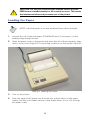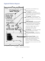
1
Title
1027 Radon Monitor User’s Guide
ACCURATE • RELIABLE • ECONOMICAL
Your Partner In Radon Measurement
s
u
n
User’s Guide, Continuous Radon Monitor
© Copyright 2009 by Sun Nuclear Corporation. All rights reserved.
The information contained in this manual is copyrighted and all rights reserved by
Sun Nuclear Corporation. Copying, duplicating, selling, or otherwise distributing
any part of this product without the prior written consent of Sun Nuclear Corporation is prohibited.
Sun Nuclear Corporation reserves the right to make periodic modifications of this
product without obligation to notify any person or entity of such revision.
This manual is written for:
Software version:
1.0.0.1
To stay current on the accessories, applications, and software for the Continuous
Radon Monitor, please visit Sun Nuclear’s website, http://www.sunnuclear.com.
Continuous Radon Monitor™ is a trademark of Sun Nuclear Corporation. Other
trademarks or trade names are the property of their respective owners.
The Continuous Radon Monitor is protected by U.S. Patent #4,871,914.
Document 102711, Rev E, 16 June 2009
Corporate Headquarters
425A Pineda Court
Melbourne, Florida 32940-7508
telephone +1 321-259-6862
fax +1 321-259-7979
e-mail: [email protected]
http://www.sunnuclear.com
ii
Contents
Preface . . . . . . . . . . . . . . . . . . . . . . iv
Conventions . . . . . . . . . . . . . . . . .iv
Button Name or Entry . . . . . . .iv
Menu Options . . . . . . . . . . . . . .iv
User Messages/Cross
References . . . . . . . . . . . . .iv
Screen Messages . . . . . . . . . . .iv
Window/Dialog Box Names . . .iv
Sun Nuclear Corporation
Symbols . . . . . . . . . . . . . . . . . .iv
Operating Information . . . . . . . . . v
Cables . . . . . . . . . . . . . . . . . . . . v
Water . . . . . . . . . . . . . . . . . . . . v
Inspect Before Use . . . . . . . . . . v
Operator and Data Evaluation . . .vi
About Radon . . . . . . . . . . . . . . . .vi
Printer Battery Pack . . . . . . . . . .
Inserting the Battery Pack . . .
Removing the Battery Pack . .
Charging the Battery Pack . . .
Low Printer Battery
Indication . . . . . . . . . . . . .
Efficient Printer Battery Use .
Printer Switch Settings . . . . . . .
Transfer Data to a Personal
Computer . . . . . . . . . . . . . . . . . . .
Description . . . . . . . . . . . . . . . .
Connection . . . . . . . . . . . . . . . .
Windows Software . . . . . . . . . .
System Requirements . . . . . . . .
Installing the Software . . . . . . .
Starting the Software . . . . . . . .
Com Port Setup . . . . . . . . . . . . .
Information Setup . . . . . . . . . . .
Data Transfer . . . . . . . . . . . . . . .
Editing and Printing Reports . . .
Saving Reports . . . . . . . . . . . . .
Introduction . . . . . . . . . . . . . . . . . . . 1
Description . . . . . . . . . . . . . . . . . . 1
Application . . . . . . . . . . . . . . . . . . 1
Parts . . . . . . . . . . . . . . . . . . . . . . . 2
Options and Accessories . . . . . . . 2
Specifications . . . . . . . . . . . . . . . . 3
16
16
17
17
18
18
18
21
21
21
22
22
22
23
24
24
26
27
28
USB to Serial Adapter . . . . . . . . . 29
Introduction . . . . . . . . . . . . . . . . 29
System Requirements . . . . . . . . 30
USB to Serial Adapter Installation .
30
Newer Drivers for USB to
Serial Adapter . . . . . . . . . . 31
Verifying the USB to Serial
Adapter Installation . . . . . . . . 33
Using the Adapter with the
Radon Monitor . . . . . . . . . . . 34
Troubleshooting the USB to
Serial Adapter . . . . . . . . . . . . 35
Removing Drivers . . . . . . . . . . . 36
Palm PDA Conflicts . . . . . . . . . . 36
Pocket PC PDA Conflicts . . . . . . 37
USB Troubleshooting Chart . . . 38
Controls . . . . . . . . . . . . . . . . . . . . . . 4
Operation . . . . . . . . . . . . . . . . . . . . . 7
Unpacking . . . . . . . . . . . . . . . . . . 7
Startup . . . . . . . . . . . . . . . . . . . . . 7
Clear Memory . . . . . . . . . . . . . . . 8
Conduct Test . . . . . . . . . . . . . . . . 8
Display Result . . . . . . . . . . . . . . . 9
Print Report . . . . . . . . . . . . . . . . . 9
Download Report . . . . . . . . . . . . . 9
Shutdown . . . . . . . . . . . . . . . . . . . 9
Delayed Reports and Displays . . . 9
Optional Printer . . . . . . . . . . . . . . . 11
Parts . . . . . . . . . . . . . . . . . . . . . . 11
Description . . . . . . . . . . . . . . . . . 11
Printer Connection and
Controls . . . . . . . . . . . . . . . . . 12
Loading the Paper . . . . . . . . . . . 13
Print Report . . . . . . . . . . . . . . . . 14
Typical Printer Report . . . . . . . . 15
Interpreting Measurement
Results . . . . . . . . . . . . . . . . . . 16
Alternate Power Supplies . . . . . . 39
User Maintenance. . . . . . . . . . . . .
Troubleshooting . . . . . . . . . . . .
Changing the Backup Battery . .
Service and Calibration . . . . . . .
iii
40
40
40
41
Preface
Conventions
Button Name or Entry
Bold typeface indicates an action or selection, for example:
•
A button name (such as, ”press the Avg button”), OR
•
A screen selection (such as, “click Next to continue”).
Menu Options
Bold italicized typeface indicates a menu selection, such as, “select File > Print
from the menu”.
User Messages/Cross References
Text within double quotes indicates a cross referenced subsection, such as,
“...see “Typical Printer Report” on page...”.
Screen Messages
Italicized typeface within double quotes indicates a message that is displayed on
the screen, (such as, “Listening for data on Com X...”).
Window/Dialog Box Names
Text within single quotes indicates a window or dialog box name, such as, “the
‘Information Setup’ dialog box is displayed.”).
Sun Nuclear Corporation Symbols
The following symbols are used in this document and in Sun Nuclear Corporation’s product labels.
WARNING: Risk of electric shock.
!
WARNING: Possible impact to personal safety.
!
CAUTION: Cautionary statement.
iv
Note: Important or supporting information.
Manufacturer’s Identification (name and address).
Date of Manufacture.
Serial Number.
Catalog Number.
Consult instructions for use.
Operating Information
Cables
•
To protect insulation, never pull on a cable to disconnect it. Always grasp the
plug or connector.
•
Do not use any cable that is damaged or has broken insulation. Replace the
cable immediately.
Water
•
Do not permit water or any other liquids to spill onto the instrument.
Inspect Before Use
•
Inspect all cables periodically for damage. If any mechanical or electrical
degradation is suspected, contact Sun Nuclear Corporation for repair or
replacement.
•
Inspect the device periodically for damage. If measurement errors or device
damage are suspected, contact Sun Nuclear Corporation.
v
Operator and Data Evaluation
This manual is intended for an operator who is experienced with the use of radon
detection devices. The device and its accessories must not be used for any other
purpose than described in this manual. Violation may result in loss of warranty.
About Radon
The U.S. Environmental Protection Agency (EPA) maintains a comprehensive web
site on radon at: http://www.epa.gov/iaq/radon/ where you can find PDF and
HTML-ready versions of all of EPA's documents, brochures, and publications
relating to radon.
Below are descriptions of three of the more common EPA publications on radon,
copied from site http://www.epa.gov/iaq/radon/pubs/index.html.
A Citizen's Guide to Radon — The guide to protecting yourself and your family
from radon.
This recently revised guidance offers strategies for testing your home for radon
and discussions of what steps to take after you have tested, as well as
discussions about the risk of radon and radon myths. EPA 402-K-09-001, January
2009. (www.epa.gov/radon/pubs/citguide.html)
Home Buyer's and Seller's Guide to Radon
This booklet is intended for anyone who is buying or selling a home, real estate
and relocation professionals, home inspectors and others. EPA 402-K-09-002,
January 2009. (www.epa.gov/radon/pubs/hmbyguid.html)
Consumer's Guide to Radon Reduction — How to Reduce Radon Levels in Your
Home...
This recently revised booklet is for people who have tested their home for radon
and confirmed that they have elevated radon levels—4 picoCuries per liter (pCi/L)
or higher. This booklet can help you: select a qualified contractor to reduce the
radon levels in your home, determine an appropriate radon reduction method,
and maintain your radon reduction system. EPA 402-K-06-094, December 2006.
(www.epa.gov/radon/pubs/consguid.html)
vi
Introduction
Description
The Model 1027 Professional Continuous Radon Monitor is a patented electronic
device that uses a diffused-junction photodiode sensor to measure the
concentration of radon gas.
Figure 1. Continuous Radon Monitor
The unit is operated from standard line power and includes a 9-volt battery which
provides backup power. A numerical display shows the average radon gas
concentration.
The Model 1027 Radon Monitor has been evaluated and accepted by:
•
National Radon Safety Board (NRSB); Device code: 31807; Group Code: CR.
•
National Environmental Health Association National Radon Proficiency
Program (NEHA-NRPP); Device Code: 223; Group Code: 4.
Application
In a typical test the user locates the Radon Monitor in the home to be monitored,
connects power, and leaves it unattended for a period of two or more days.
Ambient room air diffuses into the monitor’s detection chamber. Radon decay
by-products emit alpha particles which are detected by the photodiode.
At the end of the monitoring period, the results are available in any of three forms:
numerical display on the control panel, printed report on the optional printer, or
computer display. Once downloaded to the computer, a report can be printed
using standard programs.
1
After obtaining the report data, the memory can be cleared and a new test can
begin. The instrument is completely reusable and requires no supplies except
power and an optional backup battery.
The printer need not be present during testing. The radon monitor can be moved
from the test site, and the report printed later. If multiple tests must be run
simultaneously, a single printer or computer can support many radon monitors.
Parts
After unpacking, identify the following parts:
Table I. Parts Furnished with the Model 1027
Part Number
102730
Qty
1
Description
Professional Continuous Radon Monitor, Model 1027
700050
1
Power supply
801032
1
RS-232 (serial) cable, DB9M to DB9F, 6 ft.
1029030
1
CD, provides software application and user’s manual
Options and Accessories
Contact Sun Nuclear Corporation to order any of the following optional
accessories:
•
P/N 850029: USB to Serial Adapter
•
P/N 102750: Thermal Printer (includes power supply, rechargeable battery,
and all cables). See “Optional Printer” on page 11.
•
P/N 102377: Report, Radon Gas Measurement, blank.
•
P/N 102378: Sign, self-adhesive, “Warning, Closed Building Procedure”.
•
P/N 102379: Sign, plastic, hanging, “Caution, Radon Test in Progress”.
•
P/N 1028130: Sign, vinyl static clink, “Warning, Closed Building Procedure”.
NOTE: The impact printer that was offered with earlier Model 1027
radon monitor, P/N 020030), is no longer available as an accessory.
The replacement accessory is the thermal printer, P/N 102750.
2
Specifications
Table II. Model 1027 Specifications
Description
Value
Power Supply
Converter, 120 VAC to 12 VDC, 200 mA, 60 Hz
Measurement Range:
0.1 to 999 picocuries/liter (pCi/l)
Operating Range:
45 degrees F to 95 degrees F
Accuracy
±25% or 1 pCi/l, whichever is greater after 24 hours
Disturbance Sensor:
Inertial switch
Data Port:
RS-232, 9-pin, D-connector allows printer data to be sent
to PC
Detector:
Diffused-junction photodiode
Measurement Interval:
1 hour (4, 8, or 24-hour intervals available by special
order)
Sensitivity:
2.5 counts per hour per picocurie per liter
Display:
3-digit display LED
Battery Backup:
One 9V alkaline battery supplies approximately 20 hours
of operation. LED indicates low battery.
Weight:
2 Lbs
Size:
8” x 4.7” x 2.5”
Operating Environment:
• 45 to 95° F (7 to 35° C)
• 20 to 80% relative humidity, non-condensing
Storage Environment:
• –22 to 122° F (–30 to 50° C)
• 10 to 90% relative humidity, non-condensing
Regulatory Evaluation:
• National Radon Safety Board (NRSB); Device code:
31807; Group Code: CR.
• National Environmental Health Association National
Radon Proficiency Program (NEHA-NRPP); Device
Code: 223; Group Code: 4.
3
Controls
1
2
3
4
5
6
7
8
15
14
13
9
11 12 10
17
16
Figure 2. Controls, Displays, and Connections
1
PRINTER PORT: This port is for a legacy printer (Model 020030) that was an
accessory for early Model 1027 radon monitors. The current printer connects
to the DATA port (see “Optional Printer” on page 11).
4
2
DATA PORT: This RS-232 data port is designed to provide a means to transfer the information from the monitor to a personal computer. The information
transferred is identical to that which is sent through the printer port. (For further information, see “Transfer Data to a Personal Computer” on page 21.)
3
BATTERY ON-OFF: This switch connects and disconnects the battery. When
ON, the battery will power the monitor whenever line power is not available.
When OFF, the battery will not power the monitor when line power is
disconnected. This switch should be in the OFF position any time the
monitor is not deployed for a test. This is important for two reasons: first, the
battery life will be reduced, and second, the monitor will continue making
measurements as long as battery power is available, which could
inadvertently affect the results of a recent test. A fresh battery will provide
about 20 hours of backup power if line power fails.
4
TOP PANEL-ENABLE/DISABLE: The key switch enables and disables the
digital display and buttons on the top panel of the monitor. When in the
DISABLE position, the monitor’s measurement performance is not affected.
The monitor will function effectively in either key position. This feature is
designed to mitigate the temptation to tamper with a test.
5
DISPLAY: 3-digit LED display. Three decimal points appear when AVG or
CUR is pressed after memory is cleared.
6
pCi/l: Picocuries per liter – the units of radon gas concentration shown on the
display.
7
AVG: When this button is pressed, the measured long-term average radon
gas concentration in pCi/l is displayed on the 3-digit display. This is the
cumulative average of the entire period since the memory was last cleared.
This value is not lost if the monitor loses all power.
8
CUR: When this button is pressed, the measured short-term radon gas
concentration is displayed. This is a rolling average of the most recent 12
hours. This value is lost if the monitor loses power.
9
PRINT or CLEAR: These two buttons function as PRINT and CLEAR only
when the YELLOW LED is blinking. To access this mode, hold both buttons
down until the YELLOW LED turns on. Then release the buttons, and the
YELLOW LED will begin to blink.
10 CLEAR: (the YELLOW LED must be blinking) When the button is pressed, the
YELLOW LED will turn off. Hold the button down until the YELLOW LED
turns on again; then release the button. The YELLOW LED and display LEDs
will blink once followed by a single blink of the YELLOW LED. The monitor
memory has been cleared. The disturbance switch is inactive for the next 15
seconds.
5
11 PRINT: (the YELLOW LED must be blinking) When this button is pressed, the
monitor sends a report of the information contained in memory to both the
PRINTER and DATA port. When the button is pressed, the YELLOW LED will
turn on. When released, the LED will turn off and data transfer begins. When
the information transfer is complete, the YELLOW LED will blink once.
12 YELLOW LED: The YELLOW LED is a function indicator. Normally it is off.
When the unit is powered up, it blinks twice, followed by a single blink,
indicating that the startup test is complete and that the unit is functioning
normally. During monitoring, the YELLOW LED blinks each time an alpha
particle is detected. If the monitor fails during monitoring, the YELLOW LED
will blink rapidly. When the buttons are in the PRINT/CLEAR mode, the yellow
LED is blinking. In this mode:
•
When the PRINT button is pressed, the YELLOW LED will turn on. When
PRINT is released, the LED will turn off and data transfer begins. When
the information transfer is complete, the YELLOW LED will blink once.
•
When the CLEAR button is pressed, the YELLOW LED will turn off. Hold
the button down until the YELLOW LED turns on again; then release the
button. The YELLOW LED and display LEDs will blink once followed by
a single blink of the YELLOW LED. The monitor memory has been
cleared.
13 LO BAT: When the RED LED is on, the battery has about two hours of life
remaining. Note: Power adapter must be unplugged for this LO BAT test.
14 POWER: The GREEN LED is on continuously when the monitor is powered
by line power, it blinks when monitor is powered by batteries only, and it is
off when LO BAT is on.
15 HV OFF: The RED LED is normally off. When on, the High Voltage circuit is
off, indicating that the monitor has failed. See “Service and Calibration” on
page 41.
16 Battery compartment: A single 9-volt alkaline battery is used as a power
backup for the monitor. The battery is NOT recharged by the monitor. A fresh
battery will operate the monitor for approximately 20 hours.
17 Power connection: The power adapter should be plugged into the monitor
BEFORE the adapter is plugged into line power.
6
Operation
Unpacking
Unpack the monitor. The package contains a monitor and key, a power adapter,
and a CD that provides software and this manual in PDF format.
NOTE: Save the packing material if you plan on returning the monitor
for periodic re-calibrations.
Startup
1
Place the radon monitor in the desired position within the space to be
monitored for radon gas. The monitor does not need to be level.
2
Plug the power adapter into the power input jack on the monitor (Figure 3).
3
Then plug the power adapter into a wall outlet that matches the power ratings printed on the power supply. The green POWER LED will turn on. Avoid
using switch-controlled outlets.
Figure 3. Connecting Power to the Radon Monitor
4
The YELLOW LED will blink twice followed by a single blink. This indicates
the monitor has performed all internal diagnostics and is functioning
properly.
5
Activate the top panel controls by inserting the key and turning to the
ENABLE position.
6
Press the AVG button. If the memory is clear, three decimal points will
appear in the display area. If the memory is not clear, the AVG button will
cause the long term average radon concentration to be displayed.
7
Clear Memory
1
Press and hold both push button switches on top until the yellow LED turns
on; then release the push buttons. The yellow LED will begin to blink.
!
CAUTION: Clear the memory before starting a new
measurement. If the memory is not cleared, the new
measurements will be averaged with the old measurements that
are still in memory.
2
While the yellow LED is blinking, press and hold the CLEAR button. At first
the yellow led turns off; then the yellow LED turns on continuously, not
blinking.
3
Release CLEAR button while the yellow LED is on continuously.
4
When the yellow LED and display LEDs blink, followed by a single blink of
the yellow LED, the memory has been cleared.
Conduct Test
1
If desired, switch on the backup battery. A fresh battery will provide about 20
hours of back-up operation.
2
Switch the top panel key switch to the DISABLE position and remove the
key.
NOTE: The tamper sensor is always active except for a 15-second
period immediately following the Clear command. To avoid a tamper
notation on the first reading, do not move the monitor once the
tamper sensor is active. In earlier models of the 1027, there were TILT
and LEVEL indicators that illuminated during this 15-second period.
The TILT sensor has been replaced with a DISTURBANCE sensor
which is more sensitive to movement. To test the tamper sensor,
CLEAR the memory and conduct a test for several hours. During the
test, try lifting or sliding the monitor. When you print the results, a “T”
should appear in the interval when the disturbance was made.
3
At the end of the monitoring period, insert the key and turn the top panel
switch to the ENABLE position.
Display Result
1
Press AVG to display the average radon concentration in pCi/l over the total
monitoring period.
2
Press CUR to display the radon concentration in the current 12-hour period.
8
NOTE: The AVG and CUR display values continue to update during
the entire test, even if the test period exceeds the maximum storage
of 90 intervals. The interval storage stops updating after 90 intervals
until the next memory clear.
Print Report
To print a report on the accessory printer, see “Print Report” on page 14.
To interpret the report, see “Typical Printer Report” on page 15 and “Interpreting
Measurement Results” on page 16.
Download Report
To display and/or print a report on a computer (PC), see “Transfer Data to a
Personal Computer” on page 21.
Shutdown
1
Unplug the power adapter from the wall outlet.
!
2
CAUTION: Switch off the backup battery. If the battery is on, the
monitor continues to operate.
Switch off the backup battery to avoid measurement interference with the
completed test and prevent depletion of the battery.
Delayed Reports and Displays
Test results can be displayed, printed, or downloaded later at another location,
provided you understand the following differences:
•
When power is disconnected, the value of the latest partial interval and the
CUR value are lost from temporary memory.
•
If power is on (including battery power) the unit continues to operate,
providing values that are averaged into the result.
If you take an AVG reading, disconnect power, then restore power later and take
a second reading; the second AVG reading may be slightly different from the first.
This is because the first AVG reading includes the value for the partial 1-hour
interval in process. This partial value is stored in temporary memory and is lost
when power is disconnected. The second AVG value is calculated using only
completed intervals stored in non-volatile memory.
9
Optional Printer
Parts
The following parts are included with the optional portable printer, P/N 102750:
Table III. Parts included with the Optional Printer, P/N 102750
Number
Description
850040
Thermal printer
022005
Power supply, 6VDC out, 2.1mm plug
801008
Line power cord for power supply, IEC Plug to USA style
750052
Rechargeable battery pack, 4.8V Ni-MH
780374
Connector, gender changer-mini 9 M-M
801032
Cable, RS-232 (serial), DB9M to DB9F, 6 ft.
850043
Thermal printer paper (roll)
Description
The optional portable printer, P/N 102750 (Figure 4) prints reports directly from the
radon monitor. It can be connected to AC power or used as a portable printer by
switching to battery power. See “Printer Battery Pack” on page 16.
Figure 4. Optional Portable Printer
This printer is not used to print reports from the computer. For computer reports,
see “Editing and Printing Reports” on page 27.
10
Printer Connection and Controls
1
Ensure that the gender changer (P/N 7800374) is connected to the serial port
at the back of the printer.
2
Connect the RS-232 (serial) printer cable (P/N 801032) to the DATA PORT on
the radon monitor and to the gender changer on the printer.
3
To operate the printer on AC power, plug the power supply (P/N 022005) into
the power connector at the back of the printer. Then, plug the detachable
power cord (P/N 801008) into the power supply and into a power source that
matches the ratings on the power supply.
•
Alternately, the printer can be operated from the rechargeable battery.
Figure 5. Printer Controls
4
Slide the Power switch (on the side of the printer) to the On (I) position.
•
The Power light will turn on (Figure 5) and blink once every second. If the
battery is low, then the light will blink once every 1/2 second.
5
To feed paper, toggle the On Line switch to the OFFLINE position (red light),
and then press the Feed button. It is only possible to feed paper when the
printer is OFFLINE.
6
Toggle the On Line switch to the ONLINE position (green light).
•
The green ONLINE light will blink if there is data in the buffer memory
when you toggle the switch to OFFLINE.
•
The red OFFLINE light indicates the printer is off line.
•
The red OFFLINE light flashes if the paper is not set or has run out.
•
Both the ONLINE and OFFLINE lights flash if there is an error.
11
!
CAUTION: Do not press and hold the ONLINE switch and the
FEED button simultaneously for 30 seconds or more. This resets
the internal switches and prevents use of the printer.
Loading the Paper
NOTE: Load the paper in an area protected from direct sunlight.
1
Unwrap the roll of thermal paper (P/N 850043) and, if necessary, cut the
leading edge straight across.
2
Open the paper cover on the printer and place the roll of thermal paper, edge
down, in the cover (Figure 6). The printing surface is on the inside of the roll.
Figure 6. Loading the Paper
3
Turn on the power.
4
Push the edge of the paper into the inlet slot at the bottom of the paper
holder until the auto-loader catches it and feeds about 10 cm of it through
the paper cutter.
12
NOTE: If the paper is set correctly, the OFFLINE light stops blinking
and stays on to indicate that the printer is still in OFFLINE mode.
5
If necessary, keep pressing the paper FEED button until the paper feeds
straight and smoothly.
Print Report
1
Connect and power up the printer and radon monitor.
2
Press and hold both push button switches on top of the radon monitor until
the yellow LED turns on continuously. Then release the buttons, and the yellow LED begins to blink.
3
While the yellow LED is blinking, press and hold the PRINT button until the
yellow LED turns on solid, not blinking.
4
Release the PRINT button.
5
The printer will begin printing a paper report.
6
When the yellow LED blinks once, information transfer is complete.
13
Typical Printer Report
Information to be filled in by
testing professional.
“T” (tamper) - Indicates
movement occurred during this
interval. The unit may have been
moved during the test.
“P” (power) - Indicates power
interrupt during this interval. The
unit may have been moved during
the test.
TABULAR DATA - Average radon
gas concentration during each
measurement interval is printed
in sequential order; reading in
rows from left to right up to a
maximum of 90, 1-hour
measurement intervals.
Overall Avg. - Long term average
since last memory CLEAR.
EPA Protocol Avg. - Long term
average less the first 4 hours of
data.
Measurement Graph - Each
radon concentration value is
graphically represented in the
same order as the tabular
printout. Scale is automatically
adjusted to show maximum value
in pCi/l.
Figure 7. Typical Printer Report
14
Interpreting Measurement Results
The 1027 radon monitor is calibrated by setting internal switches to determine
the calibration J-factor, which provides the conversion between counts per hour
and pCi/L for that monitor. A separate calibration factor is also calculated and
printed on the calibration report.
The monitor automatically multiplies the hourly measurements by the J-factor to
yield the actual pCi/L to within 5%, and then displays these results on the printed
report.
To improve accuracy, the user can manually multiply the measurement results by
the calibration factor that is listed on the calibration report for the monitor.
The measurement results on the printed report are calculated as follows:
•
The hourly measurements are the number of counts recorded during that
hour, times the J-factor, rounded to the nearest 0.1 pCi/L.
•
The Overall Average is the number of total counts, divided by the number of
hours, times the J-factor, then rounded to the nearest 0.1 pCi/L.
•
The EPA Protocol Average is calculated the same as the Overall Average,
excluding the first four hours of measurements.
Note that the average of the displayed hourly measurements and the reported
averages may not be the same. This is due to differences in the rounding. As
described above, the displayed hourly measurements are rounded each hour,
while each average is only rounded once. The reported average is thus a more
accurate measurement than averaging the displayed hourly measurements.
If the EPA Protocol Average is close enough to the 4.0 pCi/L EPA threshold that
rounding is a possible issue, additional radon measurements should help to
determine the actual radon level.
Printer Battery Pack
The rechargeable battery pack (P/N 750052) allows the user to print reports
without connecting the printer to AC power. The battery pack is automatically
re-charged when AC power is connected to the printer.
Inserting the Battery Pack
1
Turn the printer over and slide the battery cover away from the battery pack
enclosure (Figure 8).
15
Figure 8. Inserting and Removing the Battery Pack
2
Connect the battery pack wires to the connector.
3
Turn the battery pack so the label is visible, insert it in the printer, and close
the battery cover.
Removing the Battery Pack
1
Turn the printer over and slide the battery cover away from the battery pack
enclosure.
2
Pull out the battery pack, grab the connector with your thumb and index
finger, and remove it by pulling on it.
3
Close the battery cover.
Charging the Battery Pack
1
Turn the power off.
2
Connect the AC adapter to the printer. The POWER light will blink once every
second while the battery is charging. It takes about 10 hours to completely
recharge the battery. When the battery is fully charged, the power lamp
stops blinking and turns off.
3
Disconnect the AC adapter.
NOTE: Always charge the battery in a location that is 5 to 40 °C (41 to
104 °F) to avoid degradation of the battery pack.
16
Low Printer Battery Indication
When the power lamp starts blinking about once every 0.5 seconds and the
printer goes OFFLINE, connect the AC adapter. If there is data left in the memory
buffer when this happens, connect the AC adapter as quickly as possible and
push the ON LINE button.
Efficient Printer Battery Use
Battery efficiency decreases if the battery is recharged more than necessary.
Confirm whether power light is blinking and battery charge has decreased before
recharging battery.
When using the rechargeable battery, turn off the power switch after use. Leaving
the power switch on will consume battery and eventually run the battery down.
When using the AC adapter, please note that the battery gradually recharges
whether the printer is on or off. It takes about 15 hours to charge the battery with
the power on. Battery charging is temporarily disrupted while the printer is
printing and resumes automatically when printing is completed. If you are not
using the printer, turn off the power switch and unplug the AC adapter.
Printer Switch Settings
The thermal printer (P/N 1028050) has internal DIP switches that are set at the
factory. For proper operation, these switches must be set as shown (Figure 9).
Check and set the switches as follows:
1
Slide the power switch to the off position (0).
2
Slide the power switch to the on position (I) while pressing and holding the
ONLINE button.
3
Release the ONLINE button after a list of the current DIP switch settings
(Figure 9) begins to print. When the list of settings is complete, the following
prompt appears at the bottom of the printout:
“Continue? : Push On-line SW”
“Write? : Push Paper feed SW”
4
To leave the switch settings the same, push the FEED button.
5
To change any switch settings, push the ON LINE button. The prompt “Dip
SW-1” appears on the printout below the current settings.
NOTE: All eight SW-1 switches must be set to on or off before exiting.
Do not exit in the middle.
17
Figure 9. DIP Switch Settings for Printer
6
Set each of the eight switches in DIP SW-1 by pressing either ON LINE for
”on” or FEED for ”off”. As you set each switch ON or OFF the printer prints
your selection. When switch 8 is set, the printer once again prompts with
“Continue?” or “Write.” Press ON-LINE switch to “Continue” to SW-2.”
!
CAUTION: Never turn the printer off while writing the new
settings to memory. When “Dip SW setting complete” is printed,
turn the power off.
18
7
In the same manner, set the switches for SW-2 and SW-3.
8
When SW-3 is finished, press FEED to select “Write.” The changes are written to printer memory, and the printer returns to ON LINE mode.
19
Transfer Data to a Personal
Computer
Description
The DATA PORT on the Model 1027 Radon Monitor can be used to transfer data
to a computer for editing and printing.
Connection
1
To use the DATA PORT, you will need the RS-232 DB9M to DB9F cable that
is included with the Model 1027 radon monitor.
2
Connect the cable from the Model 1027 Data Port to a 9-pin Com port on any
standard PC or laptop (Figure 10).
NOTE: Newer PCs may not have Com ports. If your PC has only USB
ports, see “USB to Serial Adapter” on page 29.
Figure 10. Connecting the Data Port to a Computer
20
Windows Software
The CD that is included with the Model 1027 radon monitor provides this
document in PDF format and an installation program for the Model 1027
application software.
The CD provides the latest released software for the instrument at the time of
shipment. However, upgrades or patches may be available later, and can be
downloaded from the Sun Nuclear website, http://www.sunnuclear.com.
The Windows software application is used to:
•
print reports from any printer connected to your computer,
•
apply headers, footers, dates, and serial numbers to reports,
•
annotate and edit reports,
•
store reports as text files,
•
store reports that can be imported into a spreadsheet.
System Requirements
The Model 1027 Radon Monitor software will run on any PC operating on
Microsoft Windows Vista (32-bit), XP (32-bit), or 2000. Approximately 5 MB of disk
space and 32 MB of RAM are required.
Installing the Software
1
Place the CD in the computer’s CD drive. A copyright notice screen appears.
2
Read the notice then click Accept. An Installation Menu is displayed.
Figure 11. Installation Menu
21
3
Under the heading “1027 Radon Monitor” click the Software link, then wait
a few moments for the installation to begin.
NOTE: The installation may take a few seconds to begin. Do not click
the Software link more than once.
4
When the ‘Welcome’ screen is displayed, follow the on-screen directions.
5
When the ‘Installation Complete’ screen is displayed, click Finish to exit the
installation. The Radon 1027 icon appears on the desktop.
Starting the Software
1
Double-click on the Radon 1027 desktop icon (Figure 12) to start the program. If the desktop icon is not visible, click Start > Programs > SNC Group
> Radon 1027.
Figure 12. Desktop Icon
2
The program opens with a blank screen (Figure 13). On the menu bar, the Get
Data menu option is dimmed because a Com port has not been selected yet.
Menu bar
Editing area
Message area
Figure 13. Program Opens With a Blank Screen
22
Com Port Setup
The Model 1027 radon monitor can use Com port 1, 2, 3, or 4. Check the
connector on the computer where you connected the RS-232 cable to identify the
Com port number.
1
Click Com Port on the menu to display the available Com Ports. Unavailable
Com Ports will be dimmed.
2
Select the Com Port on the computer to which the RS-232 cable is connected. A bullet will appear next to the selected port (Figure 14).
Figure 14. Select the Desired Com Port
3
If you accidentally select the wrong port, reselect the correct port.
Information Setup
If desired, configure header and footer information to be automatically added to
each report when the data is transferred from the radon monitor. This information
is entered in a special dialog box before the data is transferred.
1
Click Edit > Info... to open the ‘Information Setup’ dialog box (Figure 15).
23
Figure 15. Information setup
2
Enter the desired information as follows:
•
Enable Info—select this item if you want the information to be placed in
the report. If the box is cleared, none of the information will appear on
the report.
•
Monitor S/Ns—enter the serial number for each of the Model 1027 radon
monitors you are using, and press the down arrow. This inserts the numbers in the list below. Prior to transferring a report to your PC, doubleclick the serial number you want to appear in the Radon Monitor S/N
box. To remove a S/N from the list, click on it and then press the Delete
key.
•
Header Info—enter the text to appear at the top of the report.
•
Start Date/Start Time—select the date and time the test started.
•
End Date/End Time—select the date and time the test ended.
•
Radon Monitor S/N—select the serial number of the radon monitor used
in the test by double-clicking the correct serial number from the list of
serial numbers in the box at the left.
•
Location—enter the location of the monitor during the test.
•
Footer Info—enter the text to appear at the bottom of the report.
3
Click the down arrow in the date box to open a calendar (Figure 16). Then
scroll to the desired month and double-click the desired date. The selected
date appears in the Date box. You can also type in the date directly or highlight the month, day or year and increment or decrement the value with the
up/down arrow keys.
4
In the time boxes, type in the times desired, or highlight the hours, minutes,
or seconds and click the arrows to increment or decrement the selected
value.
24
Figure 16. Using the calendar to select the date
5
Click OK to save the information.
Data Transfer
NOTE: At least 3 hours of data should be accumulated before transferring data.
To transfer data to a computer, perform the following steps:
1
Ensure that the Model 1027 Radon Monitor is connected and powered on.
2
Start the program by double-clicking the Radon 1027 desktop icon or by
selecting Start > Programs > SNC Group > Radon 1027.
3
When the program opens, verify that the proper Com port is selected.
4
Click the Get Data menu option. The message at the bottom of the screen
displays “Listening for data on Com X...”
5
Hold down both buttons on top of the Model 1027 until the yellow LED
comes on continuously. Then release both buttons. The yellow LED will now
be flashing.
6
With the yellow LED flashing, press and release the Print button to transmit
the data. The message at the bottom of the screen displays “Acquiring data
on Com X, please wait...”
NOTE: The ‘Acquiring Data...’ message indicates that the computer is
able to communicate with the radon monitor via the selected Com
port.
25
7
The Model 1027 report will appear on the computer screen (Figure 17).
Figure 17. Report Displayed in the Editing Screen
NOTE: If an "Index out of bounds" message is displayed after pressing
the Print button, the monitor does not have sufficient test data.
8
Use the scroll bars on the right side and the bottom of the screen to view
other parts of the report.
Editing and Printing Reports
1
The entire central part of the screen is an editing window. Text can be added,
deleted, or changed in any part of the report.
2
Use standard Windows keystrokes to enter or delete characters.
3
Use the Cut, Copy, and Paste commands on the Edit menu to make major
changes to the report.
4
To interpret the results of the report, see Figure 7, page 15. The data
between the header and footer is the same as on the optional printer tape.
5
To print the report, select File > Print. A Windows Print dialog box opens.
6
Click OK to print.
26
Saving Reports
1
A report can be saved in one of two formats:
•
Normal ASCII text format (“Text Files”). The program adds the suffix “_t”
to the filename.
•
Text format suitable for importing into a spreadsheet, such as Microsoft
Excel (“Import Friendly Files”). The program adds the suffix “_s” to the
file name. In this format, the numerical data is tab-delimited so that
when imported into a spreadsheet program, numerical values are placed
in individual cells. This format allows the use of graphing functions and
other spreadsheet tools on the data.
2
Click Save As on the File menu. The ‘Save As’ dialog box opens. By default,
the files are saved in the C:\Radon\Data subdirectory.
3
Click the Save as Type drop-down list to select the type of format to use (Figure 18).
Figure 18. Save As Dialog Box
4
Type a name for the file. Use a naming scheme that is suitable to your
purpose. It could be the client name, address, date, serial number, or some
combination. The appropriate suffix will be added automatically depending
on the selected file format.
5
Click Save.
27
USB to Serial Adapter
Introduction
A computer can be connected to the Model 1027 radon monitor using an RS-232
cable to the DATA PORT on the monitor. This provides the ability to download data
and print reports on the computer.
However, many newer computers have USB (Universal Serial Bus) ports instead
of RS-232 (COM) ports. If this is the case, a “USB to Serial Adapter” cable can be
used to connect the radon monitor to the USB port on the computer. A typical
adapter usually has a short cable with a serial connector on one end, a USB
connector on the other end, and a small circuit board molded to the connector.
Sun Nuclear has tested and approved a USB to Serial Adapter for this purpose
(IOGEAR model GUC232A, Figure 19). This adapter can be purchased directly
from Sun Nuclear by ordering P/N 850029, or it can be purchased at a computer
store, office supply store, or from an internet supplier.
Figure 19. IOGEAR Model GUC232A USB to Serial Adapter
Although it is possible to use a different USB to Serial Adapter, it is not
recommended. USB to Serial Adapters require a special installation procedure on
your computer, and each manufacturer supplies instructions for this installation.
The installation procedure for the IOGEAR model GUC232A USB to Serial Adapter
has been tested and approved for use with the Model 1027 radon monitor. Other
USB to Serial Adapter installations have not been tested.
!
CAUTION: Sun Nuclear will only provide technical support for
the IOGEAR Model GUC232A adapter.
28
System Requirements
The IOGEAR Model GUC232A USB to Serial adapter can be used with a
computer that is running Microsoft Windows Vista (32-bit), XP (32-bit), or 2000.
The device drivers for Windows Vista 64-bit are not supported at this time.
To determine whether your computer is running a 32-bit or a 64-bit edition of
Windows Vista, perform the following steps:
1
2
Select Start > Control Panel and then do one of the following
•
If the Control Panel is in default view, click System and Maintenance
and then on the next screen click System.
•
If the Control Panel is in classic view, then double-click System.
The ‘System Type’ line will display either ‘32-bit Operating System’ or ‘64-bit
Operating System’.
If your computer is running Windows Vista 64-bit, you cannot use the IOGEAR
Model GUC232A USB to Serial Adapter to connect to the radon monitor at this
time. The alternatives are:
•
Use a USB to Serial adapter from a different manufacturer (not recommended - Sun Nuclear will only provide technical support for the
IOGEAR Model GUC232A adapter).
•
Use another computer with a compatible operating system to connect
to the radon monitor.
•
Use a computer with a serial port to connect to the radon monitor.
•
Output measurement results to the thermal printer instead of to the
computer.
•
Upgrade to a Model 1028 or 1029 Radon Monitor.
USB to Serial Adapter Installation
NOTE: To perform this procedure, you may need to be logged into
the computer as a user with administrative privileges.
The following items are required to perform this procedure:
•
USB to Serial Adapter
•
CD and manufacturer’s instructions that were provided with the USB to
Serial Adapter.
•
RS-232 cable that was included with the Model 1027.
1
Connect the RS-232 cable from the Model 1027 Data Port to the serial
connector on the USB to Serial Adapter (Figure 20).
29
Figure 20. Connecting the USB to Serial Adapter
2
Plug the USB connector on the other end of the USB to Serial Adapter into
one of the USB ports on the computer (Figure 20).
!
CAUTION: Do not throw away the CD or the manufacturer’s
instructions for the USB Serial Adapter. The CD and instructions
are needed to install the software drivers for the adapter.
3
Insert the manufacturer’s CD into the CD drive of your computer.
4
Normally the CD drive is set for Autostart and the installation program will
open automatically. If not, use My Computer or Windows Explorer to navigate to the CD and manually start the program in accordance with the
manufacturer’s instructions.
5
Follow the manufacturer’s instructions on the screen.
Newer Drivers for USB to Serial Adapter
If the CD that is included with the USB to Serial adapter does not provide the
correct drivers for your operating system or if you would like to see if newer
drivers are available, you can go to the adapter manufacturer’s website and
download the latest drivers for your operating system.
1
For the recommended USB to Serial Adapter (IOGEAR model GUC232A, Sun
Nuclear P/N 850029), go to the IOGEAR web site (www.iogear.com) and
download the latest drivers using the following steps.
•
Click the Support link and then select Drivers/Manuals.
30
•
In the ‘Search for your product’ box, select the Driver radio button and
then type GUC232A in the box. A link to the driver will be displayed
below the search box.
•
Click the link below the search box to display a list of available drivers for
this adapter.
•
Click the Download link for the operating system that you are using.
NOTE: Vista 64-bit drivers are not supported at this time. See “System
Requirements” on page 30.
•
A ‘File Download window’ is displayed. Click Save to display the ‘Save
As’ window, and then save the file to your hard drive.
2
If the downloaded file is compressed (*.zip or *.rar format), use an unzip
utility to extract the contents of the file to your hard drive.
3
Disconnect and then reconnect the USB end of the adapter from the computer. The ‘Found New Hardware Wizard’ window will be displayed.
4
Click Locate and install driver software (recommended).
5
If Windows requests permission to continue, click Continue.
•
Windows may search for the drivers on the internet and install them if it
finds them. Otherwise, continue with Step 6 below.
6
If the ‘Insert the disc’ dialog box opens, click I don’t have the disc. Show me
other options.
7
If Windows can’t find the driver software, click Browse my computer for
driver software (advanced).
8
When prompted for the location of the driver software, click the Browse
button, then navigate to the directory where you saved the driver files (Step
1) or if the files were extracted, navigate to the location where you extracted
the files (Step 2). If the files are in subfolders for several operating systems,
choose the correct subfolder for your operating system.
9
Click Next to install the driver. When the driver is installed, the screen shows
that the software for the USB to Serial Adapter was successfully installed.
10 Click Close.
31
Verifying the USB to Serial Adapter Installation
NOTE: To perform this procedure, you may need to be logged into
the computer as a user with administrative privileges.
Use the following procedure to verify that the USB to Serial Adapter Drivers were
installed correctly.
1
Perform the steps in the following table to open the 'Device Manager'
window on your computer. This is the window that is used to check the com
port connection. Use the procedure that is appropriate for your operating
system.
Table 4. Steps to Open the ’Device Manager’ Window
Windows Vista
Windows XP
•
On the desktop, right-click the My
Computer icon, then select
Properties to display the 'System
Properties' window.
•
On the desktop, right-click the My
Computer icon, then select
Properties to display the 'System
Properties' window.
•
Click the Hardware tab, then click the
Device Manager button.
•
Click the Hardware tab, then click the
Device Manager button.
•
If you are prompted for an
administrator password or
confirmation, type the password or
provide confirmation.
•
•
If the above steps do not work, click
the Start button. In the ’Start Search’
box, type Dev and wait for a list to be
displayed above the search box.
Select Device Manager from the list.
If the above steps do not work, click
the Start button then click Control
Panel. In the ’Control Panel’ window,
double-click System. In the ’System
Properties’ window, click the
Hardware tab, then click the Device
Manager button.
2
In the ’Device Manager’ window, follow these steps to select the appropriate
Com port:
a.
Click the plus sign (+) next to PORTS to see a list of connected ports
(Figure 21).
b.
In the ports list, look for the port labeled ATEN USB to Serial Bridge
(com#) if you are using the recommended IOGEAR USB to Serial
adapter, or look for something similar to USB Serial Port (com#) if you
are using a different USB to Serial adapter.
c.
Verify that it is the correct port by disconnecting and reconnecting the
USB end of the cable from the computer. The port should disappear
from the list and then reappear.
• If none of the ports disappear and reappear when you disconnect
and reconnect the cable, the computer does not "see" the USB to
32
Serial Adapter. Reinstall the drivers that were provided with the USB
to Serial Adapter, and then try this procedure again.
Figure 21. Checking USB to Serial Port in Device Manager
3
Make a note of the serial port number (Com number) of the USB to Serial
adapter that you are using. You will need it to set the Radon Monitor software to connect to this port.
Using the Adapter with the Radon Monitor
1
After the USB to Serial Adapter is successfully installed, power up the radon
monitor and launch the Radon Monitor software.
2
On the menu, click ComPort and select the Com port number that is set up
for the USB to Serial Adapter (Figure 22).
Figure 22. Selecting Com Port in Radon Monitor Software
33
NOTE: SNC model 1027 Radon Monitor software will only recognize
Com ports 1, 2, 3, or 4. Ports that are dimmed on the menu are not
available on your PC.
3
Click Get Data on the menu. A message “Listening for data on Com X...” will
appear at the bottom of the screen.
4
Press the two switches on the radon monitor simultaneously until the yellow
LED comes on solid, then release them. The yellow LED will flash.
5
Press the Print button on the monitor. The message at the bottom of the
screen displays “Acquiring Data on Com X - Please Wait...” In a few seconds,
the data will appear on screen.
NOTE: The ‘Acquiring Data...’ message indicates that the computer is
able to communicate with the radon monitor via the selected Com
port. If you do not see the ‘Acquiring Data’ message, see “Troubleshooting the USB to Serial Adapter” .
Troubleshooting the USB to Serial Adapter
The steps in this subsection are for users who: 1) already connected a USB to
Serial adapter, 2) installed the drivers for the adapter following the cable
manufacturer’s instructions, and 3) are unable to download data from the radon
monitor to the software.
Typically, this is caused by the Com port number that was assigned to the adapter
cable. The Model 1027 software only recognizes Com ports 1 through 4, so if the
cable uses Com port 5 or higher the software will not recognize the cable.
Perform this procedure to change the Com port assignment to 4 or lower.
NOTE: To use this procedure you may need to be logged in to the
computer as an administrator.
1
Make sure the radon monitor is OFF and the radon monitor software is
closed.
2
Open the ‘Device Manager’ window (for instructions to open this window
see Step 1 of “Verifying the USB to Serial Adapter Installation” on page 33).
3
In the ‘Device Manager’ window, click the plus sign (+) next to PORTS to see
a list of connected ports.
4
In the ports list, look for the port labeled ATEN USB to Serial Bridge (com#)
if you are using the recommended IOGEAR USB to Serial Adapter, or look for
something similar to USB Serial Port (com#) if you are using a different USB
to Serial Adapter cable.
34
5
Verify that this is the correct port by disconnecting and then reconnecting the
USB end of the cable from the computer. The port should disappear from the
list and then reappear.
•
If none of the ports disappear and reappear with the above test, the
computer does not "see" the USB to Serial Adapter. Reinstall the drivers
that were provided with the adapter and then try this procedure again.
See “USB to Serial Adapter Installation” on page 30.
6
Double-click the port. The Com port properties window is displayed.
7
Click the Port Settings tab at the top, and then click the Advanced button in
the middle of the screen. This displays the 'Advanced Settings' window for
the port.
8
Click on the drop-down box with the com port number in it. The ports that
are not available are labeled "in use". Select available port 1, 2, 3, or 4.
!
9
CAUTION: If ports 1 through 4 are labeled "in use", the ports may
be assigned to a connected device OR to the software for a device
(reserved for use when the device is connected). Although it may
be possible to successfully connect via a port that is marked "in
use", this might cause a device or software program on your computer to malfunction - proceed at your own risk! Sun Nuclear is
not responsible for any damage to your computer as a result of
selecting a com port that is labeled "in use".
Click the OK button to save your com port selection then close the window.
10 In the com port properties window, click OK.
11 Close all of the other windows that you opened through the ’Device
Manager’.
12 Return to the “Using the Adapter with the Radon Monitor” procedure on
page 34 and select the same Com port number that you selected in step 6 of
this procedure.
Removing Drivers
If you want to reinstall the drivers or change to a different device, it may be
possible to remove the installed drivers via a software process. Refer to the
manufacturer’s instructions for details.
Palm PDA Conflicts
The USB to Serial Adapter may conflict with the HotSync Manager of a Palm PDA
installation if HotSync Manager is loaded and the connection is set to use the
same Com port as the USB to Serial Adapter.
35
1
Right-click the HotSync Manager icon in the task bar tray at the lower right
corner of the screen. A pop-up menu appears (Figure 23).
Figure 23. Palm HotSync Manager Quick Menu
2
Left-click to clear the check mark on Local Serial.
3
Before using the Palm HotSync cradle the next time, reset HotSync Manager
to Local Serial.
Pocket PC PDA Conflicts
A similar conflict may exist with ActiveSync settings of a PDA with Microsoft’s
Pocket PC operating system. However, there is no easy way to turn off
ActiveSync. Eventually Microsoft may provide a patch for this that can be
downloaded and installed.
In the meantime, a free utility called “ActiveSync Toggle” can be downloaded from
www.micrologics.co.uk. According to many users, this product can be used to
temporarily disable ActiveSync while using the USB to Serial Adapter. Later, it can
be used to enable ActiveSync to continue using the computer with a PDA.
!
CAUTION: Use “ActiveSync Toggle” at your own risk. Sun
Nuclear Corporation is not responsible for any damage to your
PC or Windows installation.
36
USB Troubleshooting Chart
Table V. USB to Serial Adapter Troubleshooting
Indication
Probable Cause
Remedy
Can’t find manufacturer’s CD Lost or discarded
or drivers
Download from manufacturer’s
website
Yellow exclamation point or Incorrect installation
question mark next to USB to
Serial Adapter in Device
Manager
Reinstall drivers per manufacturer’s recommendations.
Warning message that Com Conflict with another
port is in use
serial device
Disconnect the other serial
device; disable HotSync or
ActiveSync; reinstall USB to
Serial Adapter.
Installation assigns Com port Other serial devices
to number higher than 4
installed
Un-install one serial device
installed in Com ports 1 through 4
and reinstall USB to Serial
Adapter.
Radon Monitor software
does not download data
Wrong Com port
selected
Select correct Com port.
Data not sent from
Radon Monitor
Select Get Data on menu, press
AVG and CUR buttons on Radon
Monitor simultaneously, release
when YELLOW LED solid; press
PRINT button when LED is
flashing.
37
Alternate Power Supplies
If your line power is different from 120 VAC, 60 Hz you may use locally available
AC line adapters that conform to the following specifications:
Radon Monitor Model 1027 Input Power Specification:
•
9-12 VDC or VAC, 200 mA minimum
•
Plug: 5.5 mm OD, 2.5 mm ID
Printer P/N 020030 Input Power Specification:
•
9 VAC, 1.5 A
•
Printer plug: 1.6 mm ID, spaced 3.81 mm, center-to-center
•
Connector is a 2-wire socket which can be cut from the 110 VAC adapter and
spliced onto the locally provided adapter.
38
User Maintenance
Troubleshooting
Table VI. Model 1027 Troubleshooting
Trouble
Recommended Action
YELLOW LED continuously
blinking
Monitor has failed – contact Sun Nuclear
HV OFF LED is on
continuously
High Voltage supply is off. Monitor has failed - contact Sun
Nuclear.
Printed report states “NO
DATA” after a test
Monitor did not have power – run monitor again in location
with known reliable power. Ensure that battery switch is
ON and POWER LED is ON.
Printed report has only a
partial report
Printer was not READY when print button was pressed –
re-print report.
Average measured value is
higher or lower than expected
and a change in hourly readings occurred in mid-report.
Count the number of hourly measurements to make sure
the number coincides with the number of hours actually
deployed. If the number is greater, then the monitor was
not properly cleared after the previous test, and previous
measurements are being averaged in with data from the
current test.
Battery is dead
Battery switch was left on when line power was removed.
The unit continued to monitor until battery was depleted.
Printed report is too light.
Replace printer paper.
Monitor has an AVERAGE
The monitor has lost power recently, which cleared the
value, but no CURRENT value CURRENT value. However the AVERAGE is maintained
until it is deliberately CLEARED.
“Index out of bounds” message displays after pressing
the Print button.
Not enough data collected. Accumulate at least 3 hours of
data before transferring to a computer.
For more help, see Sun Nuclear Corporation’s web site for Product FAQs,
information, and bulletin board: http://www.sunnuclear.com.
Changing the Backup Battery
To change the backup battery, pull out on one end of the hinged battery
compartment door (Figure 24).
Remove the battery from the connector, install a new 9V alkaline battery, and
close the door.
39
Figure 24. Changing the 9 V Backup Battery
Service and Calibration
WARNING: The unit contains high-voltage circuits. Do not
open the case. There are no user-serviceable parts inside the
unit.
For service or calibration, the unit must be returned to Sun Nuclear Corporation.
See the Warranty statement on the inside back cover of this manual.
The recommended calibration frequency for the 1027 radon monitor is one year.
40
Warranty
1
Instrumentation
a.
This instrument and its accessories, excluding those listed in 1.D. below, are warranted by SUN NUCLEAR CORPORATION, against defects in materials and
workmanship for a period of one year from the date of original purchase from
SUN NUCLEAR CORPORATION. During the warranty period, SUN NUCLEAR
CORPORATION will repair, or at its option, replace an instrument found to have
such defect, at no charge to the customer.
THERE ARE NO WARRANTIES, EXPRESSED OR IMPLIED, INCLUDING WITHOUT
LIMITATION, ANY IMPLIED WARRANTY OF MERCHANTABILITY OF FITNESS,
WHICH EXTEND BEYOND THE DESCRIPTION ON THE FACE HEREOF. THIS
EXPRESSED WARRANTY EXCLUDES COVERAGE OF AND DOES NOT PROVIDE
RELIEF FOR INCIDENTAL OR CONSEQUENTIAL DAMAGES OF ANY KIND OR
NATURE, INCLUDING BUT NOT LIMITED TO LOSS OF USE, LOSS OF SALES OR
INCONVENIENCE. THE EXCLUSIVE REMEDY OF THE PURCHASER IS LIMITED
TO REPAIR, RECALIBRATION, OR REPLACEMENT OF THE INSTRUMENT AT THE
OPTION OF SUN NUCLEAR CORPORATION.
2
3
b.
This warranty does not apply if the product, as determined by SUN NUCLEAR
CORPORATION, is defective due to either abuse, misuse, or modification or service performed by someone other than a SUN NUCLEAR CORPORATION
authorized repair and calibration facility. Misuse and abuse include, but are not
limited to, subjecting the instrument to environmental conditions outside the
specified limits or allowing the instrument to become contaminated by radioactive materials.
c.
In order to obtain warranty repair service, the instrument must be returned,
freight prepaid, to the facility cited in 3.b. below. The purchase date, vendor
invoice, or customer purchase order should be included, along with a statement
of the problem. Instruments will be returned transportation prepaid to points
within the United States.
d.
Because the original manufacturer’s warranty applies, the following items are
specifically excluded from this warranty: photomultiplier, Geiger-Mueller, and
proportional tubes; batteries; ancillary devices, including, but not limited to, printers, computers, display devices, etc.; and other components as may be specified
in this manual.
Calibration
a.
This instrument is warranted to be within its specified accuracy at the time of
shipment. If a question arises and SUN NUCLEAR CORPORATION determines
that the initial calibration is in error, the instrument will be re-calibrated by SUN
NUCLEAR CORPORATION at no charge. SUN NUCLEAR CORPORATION is not
responsible for calibrations performed by independent laboratories, nor any calibration fees incurred prior to or subsequent to SUN NUCLEAR CORPORATION
warranty service.
b.
The return policy is as stated in 1.c. above.
Non-warranty Service
a.
Repairs and/or replacements not covered by this warranty may be performed by
SUN NUCLEAR CORPORATION or a factory authorized service location. Estimates of repair charges may be requested; however, a charge for estimate
preparation may apply if the repair is later not authorized by the customer.
The cost of transportation into and out of the service location will be the responsibility of the customer. The instrument should be shipped to:
SUN NUCLEAR CORPORATION
425-A Pineda Court
Melbourne, FL 32940 U.S.A
Phone (321) 259-6862
Fax (321) 259-7979
Corporate Headquarters
425A Pineda Court
Melbourne, Florida 32940-7508
tel: +1 321 259-6862
web: www.sunnuclear.com