1
User’s Manual
Part A - Functions and Features
SIMPROCESS
Release 5
Copyright © 2002-2015 CACI, INC.-FEDERAL.
All rights reserved. No part of this publication may be reproduced by any
means without written permission from CACI.
The information in document is believed to be accurate in all respects.
However, CACI cannot assume the responsibility for any consequences
resulting from the use thereof. The information contained herein is subject
to change. Revisions to this publication or new editions of it may be issued
to incorporate such change.
SIMPROCESS is a registered trademark of CACI, INC.-FEDERAL.
Table of Contents
Organization of the SIMPROCESS Documentation Set ......................... 6
CHAPTER 1
Process Modeling and Analysis with SIMPROCESS................... 9
What is SIMPROCESS? ............................................................ 11
How Do You Use SIMPROCESS? ............................................ 12
SIMPROCESS Editions ............................................................. 13
SIMPROCESS Terminology and Menus ................................. 14
CHAPTER 2
SIMPROCESS Basics .................................................................. 73
SIMPROCESS Components ...................................................... 74
Model Toolbar............................................................................. 79
Adding and Editing Activities.................................................... 81
Generate Activity ........................................................................ 89
Delay Activity .............................................................................. 92
Dispose Activity........................................................................... 95
Defining an Entity ....................................................................... 96
Defining Resources and Processes........................................... 100
Simulation Setup ....................................................................... 107
Running a Simulation ............................................................... 110
Simulation Results .................................................................... 113
CHAPTER 3
Statistical Modeling Constructs ..................................................114
Random Number Generation and Standard Distributions .. 116
User Defined Distributions....................................................... 118
Input Sources............................................................................. 131
Run Settings............................................................................... 136
SIMPROCESS User’s Manual
3
Table of Contents
CHAPTER 4
Activity Modeling Constructs..................................................... 146
Entity-Related Activities .......................................................... 148
Entity Control Activities .......................................................... 158
CHAPTER 5
Resource Modeling Constructs .................................................. 181
Resources and Simulation ........................................................ 182
Defining Resources ................................................................... 183
Adding Resource Requirements to Activities......................... 186
Explicitly Getting and Freeing Resources .............................. 189
Replenishing Consumable Resources...................................... 193
Preempting Lower Priority Entities........................................ 195
CHAPTER 6
Graphical Modeling Constructs................................................. 196
Background Text....................................................................... 197
Background Graphics............................................................... 201
Importing Graphics Image Files ............................................. 202
Activity Gantt Chart................................................................. 206
Post Simulation Animation ...................................................... 215
CHAPTER 7
Activity-Based Costing ............................................................... 219
ABC and SIMPROCESS.......................................................... 220
Benefits of ABC with SIMPROCESS ..................................... 221
How to Use ABC in SIMPROCESS ........................................ 222
SIMPROCESS User’s Manual
4
Table of Contents
CHAPTER 8
Statistical Output Reports........................................................... 228
Simulation Results .................................................................... 229
Standard Report ....................................................................... 243
Custom Statistics....................................................................... 246
Real-Time Plots ......................................................................... 259
Custom Plots.............................................................................. 270
Expression Plots ........................................................................ 280
Simulation Results File ............................................................. 281
SIMPROCESS User’s Manual
5
Organization of the SIMPROCESS
Documentation Set
The SIMPROCESS documentation set consists of four manuals:
•
•
•
•
Getting Started With SIMPROCESS
SIMPROCESS User’s Manual
SIMPROCESS Metadata Manual
SIMPROCESS OrgModel Manual
All of the manuals can be opened directly from the Help/SIMPROCESS Manuals menu. Also,
each manual includes this section which provides links to the chapters in every manual. Press
the Control key when clicking any link to open the linked file in a new window. For Windows
systems, in order for links between manuals to work properly, Adobe Acrobat or Acrobat
Reader must be used to view the manuals.
Getting Started
The Getting Started With SIMPROCESS manual is a must for first time SIMPROCESS users.
This manual can also be used for evaluation purposes. The chapters are
•
•
Business Process Modeling With SIMPROCESS
Installation
6
•
•
•
Building Your First Model With SIMPROCESS
Evaluating Alternatives With SIMPROCESS
Demonstration and Reference Models
User’s Manual
The User’s Manual is divided into four parts with each part being a separate file. Part A is an excellent
reference for beginners and casual users. This part contains detailed documentation of the basic and
intermediate functions of SIMPROCESS. The chapters are
•
•
•
•
•
•
•
•
Process Modeling and Analysis with SIMPROCESS
SIMPROCESS Basics
Statistical Modeling Constructs
Activity Modeling Constructs
Resource Modeling Constructs
Graphical Modeling Constructs
Activity-Based Costing
Statistical Output Reports
Part B is a reference intended for advanced users of SIMPROCESS. This part contains detailed
documentation of the programming and library management functions in SIMPROCESS Professional
Edition. The chapters are
•
•
•
•
Reusable Templates and Libraries
Customizing a Model with Attributes and Expressions
More Advanced Model Building
Exporting Results
Part C describes the integrated tools included with SIMPROCESS Professional. The chapters are
•
•
•
•
•
•
•
•
Advanced Data Analysis
SIMPROCESS Database
Experiment Manager
OptQuest for SIMPROCESS
SIMPROCESS Dashboards
Model Bundles
Custom Reports
Scenarios
7
The Appendices are
•
•
•
•
•
•
•
•
•
•
•
Importing Version 2.2.1 Models
Activity Summary Table
SIMPROCESS File Structure
Statistical Distributions
Statistical Tools Glossary
SIMPROCESS System Attributes and Methods
External Event Files
Simulation Results File
UML Interfaces
Running Models Without GUI
SIMPROCESS and External Java Classes
Metadata Manual
The Metadata Manual describes how to build and edit SIMPROCESS metamodels, assign metamodels
to a SIMPROCESS model, and enter metadata in a SIMPROCESS model. The chapters are
•
•
•
•
•
SIMPROCESS Metadata
SIMPROCESS Metamodel Editor
Assigning Metamodels
Entering Metadata
BPEL Metadata
OrgModel Manual
The OrgModel Manual describes how to build and edit SIMPROCESS Organization and Resource
Models (OrgModels) and assign OrgModels to a SIMPROCESS model. The chapters are
•
•
•
•
SIMPROCESS Organization and Resource Models
SIMPROCESS OrgModel Editor
Assigning OrgModels
Using OrgModels with SIMPROCESS
8
CHAPTER 1
Process Modeling and Analysis with
SIMPROCESS
The goal of Process Modeling is to create a simplified but useful model of a business
enterprise. The enterprise can be a small work group or development team, a particular
division, a related set of departments, or even an entire company. The model allows an analyst
to study the Processes in a business in order to:
•
•
•
•
•
Determine bottlenecks or wasted effort
Devise revisions to the Process to correct performance problems
Select Process designs that give the best results
Provide cost justification
Establish performance targets for the new Process implementation.
Many types of tools and techniques are available for Process Modeling. Frequently, a simple
diagram or flowchart can expose the obvious redundancies, unnecessary work, and
inefficiencies in a given Process. Tools which provide simple diagramming of a Process are
called static modeling tools. However, to expose less obvious bottlenecks and costs intrinsic
to the Process requires information about the resources employed in the Process,
measurements of the Processing capacity of the resources, and some measure of the expected
workflow through the Process.
Many Process modeling tools today do not allow a quantified analysis of the Process under
study. Some of those do not take into account the:
SIMPROCESS User’s Manual
9
•
•
•
•
Time-varying nature of many Processes
Non-linear interactions among elements of a Process
Random behavior of most real Processes
Unexpected events in the business environment
The bottom line is that most Processes are not well characterized by deterministic, mathematical
models. A dynamic business Process modeling tool, which can simulate the behavior of the Process
as it responds to the events occurring in the business environment, is required to analyze time-varying
business processes.
Why Dynamic Modeling?
A computerized dynamic model simulates the flow of materials and information through the Process.
The dynamic model accounts for the random variations in how work is done and the way materials
(and information) flow through the real world. Simulation offers several advantages over a simple
pictorial abstraction of a business Process. SIMPROCESS employs discrete event simulation to capture
the time-varying nature of the Process under study.
SIMPROCESS advantages include:
•
First, the analyst can correlate the data produced by the model with measurements taken from
the real Processes to increase certainty that the model has adequately captured the essential
features of the real Process.
•
Second, the model will generate quantified Process measurements such as: excess capacity
or bottlenecks, the time it takes work items to flow through the Process, and the percentage
of time expended in value-adding Processes versus non-value-adding Processes.
•
Third, the model allows the analyst to evaluate, in quantified terms, the effects of reengineering the Process.
SIMPROCESS User’s Manual
10
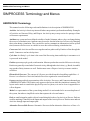
What is SIMPROCESS?
What is SIMPROCESS?
SIMPROCESS is a hierarchical and integrated Process simulation tool that radically improves your
productivity for Process modeling and analysis. SIMPROCESS is designed for BPR and IT
professionals of industrial and service enterprises that need to reduce the time and risk it takes to service
customers, fulfill demand, and develop new products.
SIMPROCESS integrates Process mapping, hierarchical event-driven simulation, and Activity-based
costing (ABC) into a single tool. The architecture of SIMPROCESS provides an integrating framework
for ABC. The building blocks of SIMPROCESS are Processes, resources, entities (flow objects),
activities, ABC, and dynamic Process analysis. ABC embodies the concept that a business is a series
of inter-related Processes, and that these Processes consist of Activities that convert inputs to outputs.
The modeling approach in SIMPROCESS manifests this concept and builds on it by organizing and
analyzing cost information on an Activity basis.
SIMPROCESS User’s Manual
11
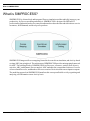
How Do You Use SIMPROCESS?
How Do You Use SIMPROCESS?
SIMPROCESS allows you to create an abstract model of a Process under study. You produce a computer
model of a business Process and documentation (diagrams and descriptions).
SIMPROCESS is a dynamic modeling tool that simulates the flow of entities through the defined
Process. Entities could be:
•
•
•
•
•
•
proposals
orders
invoices
customers
work-in-Process
patients.
Entities that a Process receives, acts upon, or produces should be included in the definition of the
business Process. Entities flow from one Process step to the next and at each step some task is performed.
The Resources, such as people, machines, or information required to complete the tasks are also
included in the business model.
SIMPROCESS generates valuable information about the Activities, Entities, and Resources in the
model. This data is used to validate the Process model. The generated statistics and reports are used
to determine where the Process could be improved. SIMPROCESS allows you to evaluate alternatives
and different management policies. SIMPROCESS helps a team decide which changes to a business
Process will provide the most benefits.
SIMPROCESS User’s Manual
12
SIMPROCESS Editions
SIMPROCESS Editions
SIMPROCESS has four editions:
•
Professional Edition - contains all the features and capabilities of SIMPROCESS. There are no
limits on model size for models built with SIMPROCESS Professional Edition.
•
University Edition - also contains all the features and capabilities of SIMPROCESS. However,
model sizes are limited to no more than 50 Processes and Activities.
•
Demonstration Edition - models are limited to no more than 25 processes and activities, 5
entity types, and 5 resource types. Also, none of the advanced features are accessible.
•
Runtime Edition - contains all the features and capabilities of SIMPROCESS except the ability
to save. There are no limits on model size, but models built or modified in this edition cannot
be saved.
SIMPROCESS User’s Manual
13
SIMPROCESS Terminology and Menus
SIMPROCESS Terminology and Menus
SIMPROCESS Terminology
This manual uses the following words and definitions in its description of SIMPROCESS.
Activities. An Activity is a basic step in a model where an operation is performed on an Entity. Examples
of Activities are Generate, Delay, and Dispose. An Activity may or may not involve passage of time
or Resource requirements.
Attributes are system and user-defined variables of model elements whose value can change during
the course of a simulation run. Attributes may be used to alter the behavior of a Process by changing
their value during a simulation. They can also be used to communicate information (such as system
time) between two Processes in a model or store data collected during a simulation run.
Connectors link Activities and Processes together and are paths used by Entities to flow through the
model. Connectors can have delay times.
Cycle time. An Entity’s cycle time is the sum of the Processing times and delays it encounters as it
is processed in the model.
Entities represents people, goods, or information. Most are produced as a result of a Process or Activity.
Entities are generally created at the Generate Activity, although other Activities (e.g., Batch, Assemble)
may produce Entity instances as well. Entities must enter a Dispose Activity to ensure statistics
collection.
Hierarchical Processes. The concept of a Process provides hierarchical modeling capabilities. A
Process is a collection of Activities and sub-Processes organized as a model network.
Layout contains graphical representations of the Activities, Processes, and Connectors that make up
a SIMPROCESS model. The Entities only appear on the layout while the simulation is running. The
layout can be made to resemble the physical layout of a system, or it can be closer in appearance to
a flow diagram.
Model is a representation of the system being studied. It is not intended to be an exact duplicate of
the system, but rather a simplified version that captures the relevant features.
Pads are small triangular graphic objects located along the border of an Activity or Process. Pads are
used for attaching Connectors to the inputs and outputs of the Activity/Process. Entities enter and exit
Activities through input and output pads.
Alternative Process/Sub-Process. Alternative Processes define alternative behaviors or flows of a
SIMPROCESS User’s Manual
14
SIMPROCESS Terminology and Menus
Process. Multiple alternatives can be associated with a Process, but only one can be active at a time.
Resources are the agents required to perform an Activity. People, computers, and trucks are all
examples of Resources. Resources may be consumable (e.g., oil or paper) or reusable (e.g., trucks).
Simulation is defined as the reproduction of the dynamic and random behavior of a business Process
with the goal of quantifying some key characteristics of the business Process.
Templates of Activities, Processes, and Resources can be stored in a Library for reuse.
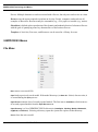
SIMPROCESS Menus
File Menu
New
creates a new model file.
Open loads a previously saved model. If the model directory (see Save As... below) does not exist, it
is created during the Open process.
Open Recent contains a list of recently opened models. The first item is Clear Menu, which removes
all recently opened models from the Open Recent menu.
is a list of SIMPROCESS file directories (Installation, Working, Models, Metamodel,
and SPUser). Selecting a directory opens the system file explorer to that directory.
Open Directory
OrgModel,
Close
closes the active model.
SIMPROCESS User’s Manual
15
SIMPROCESS Terminology and Menus
Model Properties
Group ID
opens a dialog that tracks the edit history of a model.
controls the Group ID of a model. There are two sub menu items:
• Assign Group ID
• Clear Group ID
Assign Group ID will be enabled if no Group ID is assigned to the model; if one is assigned, Clear Group
ID will be enabled. No dialog is displayed by either action. If used, the Group ID is created internally
by SIMPROCESS. Assigning a Group ID facilitates collaborative work on a model using a master
model and templates placed into a Library. (See “Reusable Templates and Libraries” for more
information on templates and Libraries.)
When a model is saved, SIMPROCESS assigns it an internal model ID. Each time a Process or Activity
is added from a template in a Library, the model ID is checked against one stored with the template
to determine whether the template was originally created from that same model. If it was, the creation
of Attributes, Resources, Entities and other items is suppressed based on the presumption that they
will already be present in the model. Each time a copy of a model is saved using the Save As command,
the internal model ID is changed. Saving a copy of the model to another name to give to team members
involved in collaborative model development is therefore not ideal. Any templates they might create
from the copy would not share the model ID of the original. This results in duplication of Attributes,
Resources, Entities and other items into the master model when the team member's efforts are merged
back into it via Library templates. The Group ID identifies models created with Save As as belonging
to the master model (using Assign Group ID on an open model causes that model to become a master
model). Save As does not change the Group ID. Thus, if the master model has a Group ID assigned,
every copy of the master model made via Save As will carry the same Group ID. When a template
is placed into a Library from any Process or Activity, the Group ID will be stored in the template along
with the model ID. When a template is added to a model, the Group ID is checked before the model
ID to avoid duplication of Attributes and other items. Only if no Group ID is present in the model
or if the Group ID of the model and the Group ID of the template do not match will the model ID
check be performed.
Save saves the model. Saving a model that has not previously been saved will execute Save As... so
the model can be named.
NOTE: It is a good idea to save a model any time you make changes to it and to save a model under
a different name any time you extensively change a model. SIMPROCESS saves your models with
the extension.spm and at the same time also saves a backup with the extension .bck. To save a new
model or to save an existing model under a new name, use File/Save As…. For information on automatic
saving, see “Other Preferences” on page 33.
Save As… is used to save a model for the first time, or to save a model with a new name. Save As...
creates a directory for the model (referred to as the model directory) that has the model name without
extension and is in the same directory as the model file. The model directory is the default location
SIMPROCESS User’s Manual
16
SIMPROCESS Terminology and Menus
for input and output files of various types and is the preferred location for imported images (see
“Importing Graphics Image Files”) and external Java classes (see “SIMPROCESS and External Java
Classes”). Note that when performing Save As... the complete contents of the previous model directory
are copied to the new model directory.
Import
imports a SIMPROCESS version 2.2.1 or 2.2.2 model. Due to changes in the
graphical coordinate system from earlier versions of SIMPROCESS to the current version, some
cleanup will be required. See “Importing Version 2.2.1 Models” for more information.
Version 2.2.1 Model…
imports an XPDL model. (See http://www.wfmc.org for information on XPDL.) The
XPDL model will be validated against the XPDL 2.2 schema. A copy of this schema can be found
at http://www.wfmc.org/standards/docs/bpmnxpdl_40a.xsd. Validation errors may occur if the XPDL
model is based on XPDL 2.0 or earlier. If SIMPROCESS indicates there are validation errors, simply
continue with the import. Most likely the validation errors are due to a difference in XPDL versions
instead of malformed XPDL.
XPDL Model...
Not all elements of an XPDL model are imported to SIMPROCESS. The following table shows the
XPDL elements that are imported and their corresponding SIMPROCESS constructs.
XPDL Element
SIMPROCESS Construct
WorkflowProcess
Process
ActivitySet
Process
Activity
Activity
Transition
Connector
DataField
Global Entity Attribute
FormalParameter
Global Entity Attribute
Performer
Resource
Artifact
Entity Type
SimulationInformation/
TimeEstimation/Duration
Activity Delay Time
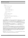
For XPDL 1.0, if x-y coordinates for Activity elements are to be imported, they must be in an
ExtendedAttribute element with the attribute Name set to Coordinates. The child element
containing the x and y values must have the attributes xpos and ypos. The name of the child element
does not matter. For XPDL 2.0 and higher, x-y coordinates are determined from the
NodeGraphicsInfo element. Below is an example of an XPDL 1.0 Activity that includes
coordinates.
SIMPROCESS User’s Manual
17
SIMPROCESS Terminology and Menus
- <Activity Id="9">
<Route />
- <TransitionRestrictions>
- <TransitionRestriction>
- <Split Type="AND">
- <TransitionRefs>
<TransitionRef Id="1" />
<TransitionRef Id="38" />
<TransitionRef Id="2" />
</TransitionRefs>
</Split>
</TransitionRestriction>
</TransitionRestrictions>
- <ExtendedAttributes>
<ExtendedAttribute Name="Coordinates">
<xyz:Coordinates xpos="572" ypos="389" />
</ExtendedAttribute>
</ExtendedAttributes>
</Activity>
The type of SIMPROCESS activity that is created is based primarily on whether or not a Route element
exists as a child of the Activity element. If there is no Route element, then the corresponding
SIMPROCESS activity is a Delay activity. If there is no Route element and there is an
Implementation/SubFlow element, the corresponding SIMPROCESS Activity is a Process.
Other factors concerning TransitionRestrictions come into play when determining other
types of SIMPROCESS Activities. As an example, the Activity element above would result in a
Split Activity in SIMPROCESS. This is because there is a Split element within a
TransitionRestriction element that has a Type of AND, and there is more than one
TransitionRef element.
Note that if the XPDL model being imported was previously exported from SIMPROCESS 4.3 or
higher, the model may contain some SIMPROCESS unique information that will help appearance.
If the XPDL model was previously exported from SIMPROCESS 5.1 or higher, the model will contain
SIMPROCESS unique simulation information. During import, if SIMPROCESS detects unique
information from other applications, this information will be transferred to the new SIMPROCESS
model. Thus, if the SIMPROCESS model is later exported to XPDL, that application unique
information will be exported as well.
MS Project File... imports a Microsoft Project file (*.mpp). The resulting model should be considered
a starting point for modeling the project detailed in Microsoft Project.
SIMPROCESS User’s Manual
18
SIMPROCESS Terminology and Menus
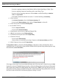
Export
Graphics Image File…
Activities
•
•
creates a JPEG image of the current layout.
contains two options:
Activity List...
outputs the Process and Activity hierarchy to an ASCII file.
Activity By Type... displays a dialog that allows Activities to be output to a comma separated file
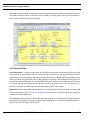
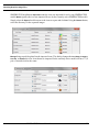
(.csv) or spreadsheet file (.xls). Comma Separated Value (.csv) is the default file type.
The output is the same no matter the type of file selected except for the Sheet Per Flow option,
which is described below.
All Activity Types is the default option for the types of Activities to export. If only certain
Activity types should be exported then select Selected Activity Types. When this option is
selected, the Activity types listed under Select Activity Types enable. This allows the export
of Activities to be restricted to certain types of Activities.
The columns included in the exported file are Parent Process Number, if Show Process
56), Parent Process
(the name of the parent Process of the Activity), Alternative (the name of the Process
Alternative of the Activity), Activity (the name of the Activity), and Activity Type (the
type of the Activity). If the Activity or Process is on the top layout, the Parent Process
Number column (if included), Parent Process column, and the Alternative column will
Numbering is selected on the View menu (see “View Menu” on page
SIMPROCESS User’s Manual
19
SIMPROCESS Terminology and Menus
be empty. The Export Options are
1. Include Duration - Adds Duration and Time Unit columns which contain the
selected duration distribution and selected duration time unit for the Activity. If
the Activity cannot have a duration there are no values for these columns.
2. Include Resources - Adds a Resources column which contains the Resources
assigned to the Activity. If there are multiple Resources assigned they are listed
separated by a comma. Each assigned Resource is followed in parentheses by the
number of units requested. For example, if one unit of Resource1 was required
the column would contain Resource1(1.0). If there are no Resources assigned or
the Activity cannot have Resources assigned there is no value for this column.
3. Include Pool/Swimlane - If there are Pools defined in the model two columns are
added, Pool and Swimlane. If only Swimlanes are defined in the model then only
a Swimlane column is added. An Activity or Process is considered to be in a Pool
or Swimlane if it is totally contained within the Pool and/or Swimlane. If any portion of the Activity or Process is outside of a Pool and/or Swimlane the Pool and/
or Swimlane columns will be empty.
4. Include Inactive Alternatives - Adds Activities and Processes from inactive as well
as active Alternatives. When it is not selected only active Alternatives will be
considered. (See “Alternative Sub-Processes” on page 101 for more information
on active and inactive Alternatives.) This option adds a column at the beginning
called Parent Process Path. This is needed since simply listing the parent Process name and parent Alternative name will not always fully identify which
Activity is referenced.
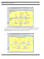
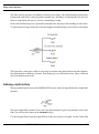
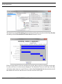
5. Activities Only In Sequence - Orders the list of Activities following the flow from
each Generate Activity. Processes are excluded. This option adds two columns,
Activity ID and Predecessor ID. The Activity ID column contains a numeric (or
alphanumeric) identification number for each Activity. Since there is only one list
of Activities, the list begins with the first Generate Activity and follows the flow
until a Dispose Activity is encountered or a loop is encountered that repeats the
flow. However, there may be multiple paths within the flow due to Branch, Split,
or other Activities. The export will follow one path to the end then go back and
add other paths. Each Activity will have one or more values in the Predecessor
ID column. This shows which Activities precede this Activity. Note that this path
may not terminate with a Dispose Activity since Activities will not be duplicated
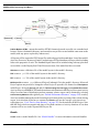
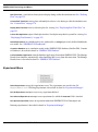
in the export. Consider the simple model below.
SIMPROCESS User’s Manual
20
SIMPROCESS Terminology and Menus
The export will start with Generate1 and then include every Activity following until
Dispose20 is reached. However, Delay11 will not be included. It will be added after
Dispose20 but the Predecessor ID value will be the Activity ID of Branch3. Also,
notice that Delay15 and Dispose20 are not repeated. See the export below.
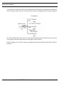
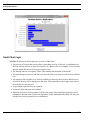
When Spreadsheet (.xls) and Activities Only In Sequence are both selected, Sheet Per
Flow is enabled. This can be a better option to examine every Activity flow. This
option creates a sheet for every unique flow in the model. The list on each sheet begins
with a Generate Activity (or Receive Transfer Activity that has no associated Send
Transfer Activity) and follows the flow until a Dispose Activity or Trigger Pad is
encountered or a loop is encountered that repeats the flow. Depending on the size
of the model and the number of path options, this could result in a spreadsheet with
many sheets. For example, the simple demonstration model CallCenter.spm
has 11 unique flows so exporting that model with these options selected results in
a spreadsheet with 11 sheets. Each sheet is named based on the name of the Generate
Activity that starts the flow. If the Generate activity is not on the top layout, the parent
Process and Alternative names are included. (Note that Excel limits a sheet name
to a maximum of 31 characters so the sheet names are adjusted accordingly. Thus,
if a sheet name error occurs, shorten the Activity, parent Process, or parent
Alternative name.) Each flow from a Generate Activity is numbered starting with
one. The same model exported with these options creates two sheets: Generate1_1
and Generate1_2. Since each sheet has a complete flow there are no Activity ID
and Predecessor ID columns.
SIMPROCESS User’s Manual
21
SIMPROCESS Terminology and Menus
outputs the model to a UML-compatible file. This feature is disabled in the
SIMPROCESS Runtime version. See “UML Interfaces” for more information.
UML Activity Model
outputs the model to an XPDL 2.2 compatible file that follows the schema at http://
www.wfmc.org/standards/docs/bpmnxpdl_40a.xsd. (See http://www.wfmc.org for information on
XPDL.) Exported XPDL models will contain some SIMPROCESS unique information. This
information is only useful to SIMPROCESS and should be ignored by other applications importing
the model. The table below shows how SIMPROCESS model constructs export to XPDL.
XPDL Model
SIMPROCESS Construct
XPDL Element
Process
WorkflowProcess
Activity
Activity
Entity Type
Artifact
Resource
Performer
Attribute
DataField
Connector
Transition
Branch Connector
Transition/Condition
Activity Delay Times
SimulationInformation/
TimeEstimation/Duration
Swimlanes
Pools/Pool/Lanes
BPEL Process creates an XML file that contains a Business Process Execution Language (BPEL)
process constructed from SIMPROCESS metadata. See the SIMPROCESS Metadata Manual for more
information.
Ultimus creates an XML file compatible with the Ultimus XML Converter. The XML file is created
in the model’s directory, and the name of the file consists of the name of the model followed by
_Ultimus.xml. The Ultimus XML Converter uses that XML file to create an Ultimus file (.wfl)
for use in Ultimus BPM Studio. See www.ultimus.com for more information on Ultimus.
Workpoint creates an XML file that can be used to create a WorkPoint archive file. The WorkPoint
archive file can be imported into WorkPoint to produce a WorkPoint process. The XML file is created
in the model’s directory, and the name of the file consists of the name of the model followed by
_WorkPoint.xml. Note that a WorkPoint process created from a SIMPROCESS model contains
minimal information and is merely intended to provide a starting point from which to begin
implementing an actual WorkPoint work flow. The table below shows the mapping of SIMPROCESS
Activities to WorkPoint objects.
SIMPROCESS User’s Manual
22
SIMPROCESS Terminology and Menus
SIMPROCESS
WorkPoint
Assemble
Activity
Assign
Activity
Batch
Activity
Branch
Optional Delay
Clone
Not Applicable
Delay
Activity or Delay
Dispose
Stop
Free Resource
Not Applicable
Gate
Delay
Generate
Activity
Get Resource
Not Applicable
Join
Optional Delay
Merge
Not Applicable
Process
Sub-process
Replenish Resource
Not Applicable
Split
Optional Delay
Synchronize
Activity
Transfer
Stop
Transform
Activity
Unbatch
Activity
The following table lists the SIMPROCESS data element on the left and the corresponding WorkPoint
data element on the right.
SIMPROCESS
WorkPoint
Process Name
Process Name
Activity Name
Activity Name
Activity Comment
Activity Description
Activity Location
Activity Display Info
SIMPROCESS User’s Manual
23
SIMPROCESS Terminology and Menus
SIMPROCESS
WorkPoint
Activity Duration
Activity Planned Duration
Delay Duration
Delay Date Offset
Connector Name
Transition Name
•
If a SIMPROCESS Connector is a Branch Connector, a dummy Workpoint transition script
is generated where the script name is the same as the Connector name and the script description
is set to the "Condition" value.
•
If a SIMPROCESS Delay Activity specifies Resource usage, a WorkPoint Activity is
generated. Otherwise, a WorkPoint Delay node is generated.
•
SIMPROCESS Entity definitions can optionally be exported to WorkPoint process user data.
The user data name will be the Entity name and the user data value will default to "X".
•
SIMPROCESS resources are exported to WorkPoint activity descriptions. If specified, the
resources are included in the activity description in the format:
"Resource=[resource1],[resource2],...[resourceN]".
•
SIMPROCESS does not identify to WorkPoint upstream (or looping) transitions. Therefore,
once the model is imported into WorkPoint, the user must locate all upstream transitions and
identify them as such by opening the transition properties and setting the appropriate checkbox.
•
In some cases, the WorkPoint import generates dummy scripts. This means, after the archive
file is imported into WorkPoint, the user must edit each of the scripts and set them
appropriately.
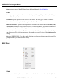
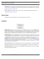
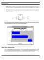
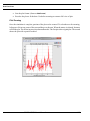
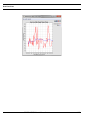
Dot Workflow creates a workflow file using the Dot language that presents a “flat” (non-hierarchical)
view of the model. The file is created in the model’s directory, and the file name consists of the model
name followed by _Dot.txt. The file can be opened in a graph visualizer such as ZRGViewer (http:/
/zvtm.sourceforge.net/zgrviewer.html). Below is a view from ZRGViewer of the CallCenter demo
model.
SIMPROCESS User’s Manual
24
SIMPROCESS Terminology and Menus
Publish Model to HTML... outputs the model to HTML format to be made accessible via a standard web
browser. Select a destination directory, and a new directory will be created with the same name as the
model (with any spaces replaced by underscores).
All layouts will be exported to JPEG image files with web pages built around them. Lists of the model's
Activities, Processes, Resources, Entities, and each type of Global Attribute will be provided, including
links to the properties of each. The Standard Report data will be included along with any plots that
are available via the Display Real-Time Plots menu item, if the model had been executed.
Slideshow
creates a slideshow file of the model layouts in the model’s directory.
PDF
creates a .pdf file of the model layouts in the model’s directory.
RTF
creates a .rtf file of the model layouts in the model’s directory.
MS Project File creates a .mpx (Microsoft Project Exchange) file in the model’s directory. Microsoft
Project options may need to be changed to allow Project to open this file format. See Tools/Options
in MS Project. Select the Security tab and click Allow loading files with legacy or non default file formats.
Activity delays in a SIMPROCESS model translate to task durations in MS Project. Since most Activity
delays are some form of distribution and not constants, a better export can be obtained by selecting
Collect Activity Statistics either globally (see “Default Performance Measures” on page 243) or on key
Activities and then running the model for multiple replications before exporting. If this is done, during
export, Activities that do not have a constant for Duration will use the average cycle time across
replications (see “Cycle Time by State Statistics” on page 255) for the task time in MS Project. Note
that MS Project does not support task times of less than a minute so Activity durations of less than
a minute will be zero in the exported MS Project file.
Bundle
Create
creates a model bundle file. See “Model Bundles” for more information on model bundles.
SIMPROCESS User’s Manual
25
SIMPROCESS Terminology and Menus
Extract
extracts a model bundle file and opens the bundled model (Model Bundles).
Print
Print Layout… prints a picture of the current model layout, including background icons, but the layout
color will not be printed.
Print Model…
prints a picture of each screen of the model. The first page is a table of contents.
Process Documentation… prints
the descriptions of selected Processes.
Model Documentation… prints the description of all elements of the model. This includes Name, Path,
and Comment field entries of all Activities/Processes, Connectors, Entities, and Resources in the model.
Any information you have added using the Document button is also included.
List of Most Recently Used Models. The File menu contains a list of the most recently used models. Open
any of these models by clicking on its name. The number of recent files is set on the Edit/Preferences
dialog.
Exit quits SIMPROCESS. If you have made edits since you last saved the open models, you will be
prompted to save your models before exiting.
Edit Menu
Undo
Undo
restores Activities, Processes, and Connectors that have been cut or cleared (deleted). It also
SIMPROCESS User’s Manual
26
SIMPROCESS Terminology and Menus
reverses Align and Distribute actions, removes Activities, Processes, and Connectors that have been
added, and reverses any move Connector actions. The Undo is only active at the hierarchical level where
the action occurred. A maximum of 30 Undo actions can be active at any one time. As editing events
occur that create Undo actions, the most recent 30 actions are the ones that are kept. The Undo menu
and the tool tip for the Undo button will update to show the next Undo action (for example Undo Clear,
Undo Cut, Undo Align, Undo Distribute). Undo actions are active in the reverse order of the editing actions
that created them. For instance, if Activities are aligned, then an Activity is deleted, the order of Undo
actions would be Undo Clear followed by Undo Align.
Cut
Cut cuts the selected object from the model layout. The cut object is copied to the clipboard, and the
object may be pasted onto a different part of the layout or into another open model using Edit/Paste.
Connectors and Pads cannot be cut. They can only be cleared.
Copy
Copy places a copy of the selected object in the clipboard. It will remain there until replaced by another
object that is cut or copied. Once a copy is made, it can be pasted on the layout or into another model
by using the Edit/Paste command.
Paste
Paste makes a copy of the object in the clipboard and pastes it onto the layout. Multiple copies of an
object can be pasted without additional copies being made. Pasting items into a model different from
the model where the copy or cut occurred can cause loss of entity, attribute, resource, function, or
distribution references. See “Advantage of Templates Over Copy/Paste” for more information.
Duplicate…
Duplicate… is a shortcut that copies a selected object from the layout and then does a paste to a position
selected on the layout. This combines Copy and Paste into one command. This is useful when you want
to quickly copy something on the layout and paste it somewhere else.
Clear
Clear
deletes a selected object without copying it to the clipboard.
Select All
Select All
selects all objects on the model layout.
SIMPROCESS User’s Manual
27
SIMPROCESS Terminology and Menus
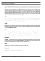
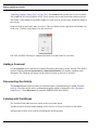
Resize
Resize lets you resize a layout object. You can resize the horizontal and vertical directions separately
if you wish to resize the icon in a non-proportional way. The values represent pixels. The Default Size
button sets the Icon Width and Icon Height to the default size of the icon. Choose the Show Handles button
if you would like to drag to resize the object. Multiple objects can be resized at the same time by having
multiple items selected when choosing Resize. Important Note: An object cannot be resized smaller
than 10 x 10 pixels. Thus, if numbers are entered that are smaller, the object will be resized to 10 x
10. Also, Background Text objects cannot be resized using Resize. The font properties must be changed
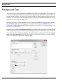
to resize Background Text.
The following image shows three processes after Show Handles was selected.
SIMPROCESS User’s Manual
28
SIMPROCESS Terminology and Menus
Switch Activity To
Switch Activity To changes an activity from one type to another. This menu item is only displayed when
one and only one activity is selected on the layout. Processes do not activate this menu item. Items
that are in common between the old activity type and the new activity type are transferred to the new
activity. Since some activities allow multiple connections to output pads and some do not, all
connections to the old activity may not transfer to the new activity. This menu item also displays on
the right mouse click contextual menu.
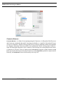
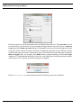
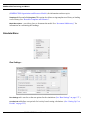
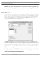
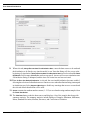
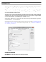
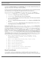
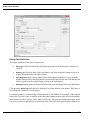
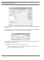
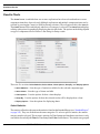
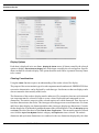
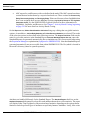
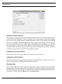
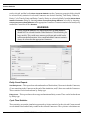
Preferences
Preferences allows the setting of personal preferences for various options in SIMPROCESS.
These
preferences take effect after the dialog is closed.
If a model is open when the Preferences menu item is selected, check boxes appear that allow selection
of preferences to be applied to the active model.
SIMPROCESS User’s Manual
29
SIMPROCESS Terminology and Menus
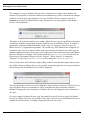
Preferences selected for application to the active model are applied when OK is clicked. Before the
selected actions are applied to the active model, a dialog confirming that these actions should occur
appears.
If No is selected, the active model is not updated. It may take a few minutes to apply updates to a large
model. Other editing actions are not allowed while the update occurs. Note that these updates actually
change the properties of the active model. The options to display or not display Activity, Pad, and
Connector names on the View menu do not change the model properties, just what is currently visible.
(See page 59.)
There are ten tabs on the Preferences dialog:
• Processes/Activities
SIMPROCESS User’s Manual
30
SIMPROCESS Terminology and Menus
•
•
•
•
•
•
•
•
•
Text Block
Text Label
Background Text
Pads
Connectors
Entities
Toolbars
Appearance
Counts
Processes/Activities
Show Name
specifies to show the name on the layout by default for newly created Activities.
Confirm Delete
causes a confirmation dialog to appear when you delete an Activity or a Process.
Auto Connect Activities causes new activities placed on the layout to automatically connect (if possible)
with any previously selected activities. The type of connector to use (Bent or Straight) is set on the
Connections tab. This option can also be turned on/off on the right mouse click contextual menu.
Display Process Badge causes a small icon (green plus sign) to display on the lower right hand corner
of non-empty Processes.
Display Master/Copy Badges causes a small icon (letter M for Master Processes and letter C for copies
of Master Processes) to display on the lower left hand corner of Processes. (See “Master Processes”
on page 103 for more information on Master Processes.)
Activity Width/Height
sets the default width and height of new Activities.
Process Width/Height
sets the default width and height of new Processes.
Default Icon Set
sets the default Icon Set for new Activities and Processes.
Text Block
Show Text Block
displays the text blocks for the Activities on the layout.
The Font Attributes set the default Font Name, Size, Color, Bold and Italic.
Text Label
The Text Label preferences are for text labels that are created from the Text Block of a Process. See
“Labeling with Text Blocks,” beginning on page 84 for information on how to use these.
SIMPROCESS User’s Manual
31
SIMPROCESS Terminology and Menus
Add Text Label
sets whether the label should be added inside the process for each alternative.
sets whether the label should be horizontal (selected) or vertical (not selected)
Horizontal Text Label
on the layout.
The Font Attributes set the default Font Name, Size, Color, Bold and Italic.
Background Text
The Font Attributes set the default Font Name, Size, Color, Bold and Italic.
Pads
Show Name
shows the pad names on the layout.
Confirm Delete
Pad Size
causes a confirmation dialog to appear when you delete a Pad.
specifies the default size of pads: Small, Medium, or Large.
Connectors
Show Name
displays Connector names on the layout.
Confirm Delete causes
Line Width
a confirmation dialog to appear when you delete a Connector.
specifies the default line width for new Connectors.
Line Style specifies
the default line style for new Connectors.
Default Connector for Auto Connect specifies the type of connector (Bent or Straight) to use when Auto
Connect Activities
on the Processes/Activities tab is selected.
Entities
Specify Default Icon Size
determines whether new Entity Types will use the values in Icon Width and
Icon Height for the default size of the animation icon. If selected, the default size is applied, not only
when an Entity Type is defined, but when the icon for the Entity Type is changed. If the size of the
icon is changed while editing the Entity Type, the new size is retained until the icon is changed. When
Specify Default Icon Size is not selected, the icon size defaults to the default size of the selected icon.
Default Icon Set
sets the default Icon Set for new Entity Types.
Toolbars
The display of the System Toolbar and Model Toolbar is optional.
SIMPROCESS User’s Manual
32
SIMPROCESS Terminology and Menus
Appearance
Sets the overall appearance of SIMPROCESS. System specifies the default appearance for the operating
system. Metal and Nimbus are other styles. The selection is applied when OK is selected.
Counts
Sets the default options for displaying Activity counts. See “Animation Settings…,” beginning on
page 65 and “Setting Activity Count Options,” beginning on page 87.
Other Preferences
Time Between Auto Saves determines the approximate amount of time between automatic saves of the
model. The automatic save feature creates a file with the same name as the current model, except with
an identifier number assigned by the system added along with the extension .tmp (for example,
MyModel41123.tmp). If the current model is new and has not been saved, the name of the temporary
file will be the model’s assigned name (Model-1, Model-2, etc.) along with an identifier number and
a .tmp extension and will be located in the models directory.
NOTE: The automatic save does not affect the .bck file. The .bck file is created or updated
when you initiate a save. See page 16 for information on the backup file.
Maximum Number of Files on Recent File List sets the number of files on the File menu. The default is
4, and the allowable values are 0 through 9.
Email contact for published models is where the email address is set that is to be used with models
published via the Publish Model to HTML feature. If an entry is present, the popup menu that appears
in published models when holding the mouse over any Process or Activity will include a “mailto” link
with this address having a default subject line containing the complete path to the Activity or Process.
This is provided so that viewers can offer feedback or ask questions. This email address is not validated.
Note that not all email clients will properly handle the use of the “?subject” portion of a mailto link.
Maximum Number of Edit Log Entries
sets the limit of entries in the model’s edit log. The default is
unlimited (0 entry).
Display Activity Properties Viewer toggles the display of the Activity Properties Viewer dialog. This
dialog can be resized and remains visible until deselected here or the dialog is closed. Note that closing
the dialog will turn off this setting. Selecting any Activity or Process on the layout will display certain
Activity and Process properties. When an Activity is selected, the Activity duration in its Duration field
displays in the Duration Information field, and the Resource usage information displays in the Resource
Usage field. When an Activity or a Process is selected, the text in its Comment field displays in the
Comment Field section, and the text of the Documentation displays in the Documentation Text section.
The File/URL field will display the contents of that same field from the Documentation tab of the
properties dialog for the selected Activity or Process. If enabled, the View button will attempt to launch
your preferred web browser (for a URL) or suitable application for the file if it contains any path
SIMPROCESS User’s Manual
33
SIMPROCESS Terminology and Menus
information. By providing easy access to key Activity or Process properties, this feature is ideal for
use in model review and validation. (See “Common Activity Input Fields” on page 81.)
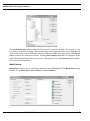
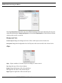
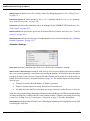
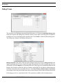
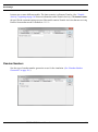
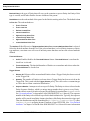
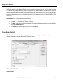
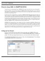
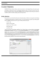
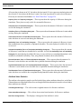
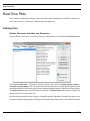
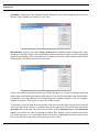
Activity Browser...
Activity Browser... is a feature for navigating among the Activities. A dialog lists all the Activities and
Processes contained in the model. Any name preceded by a (+) signifies a hierarchical Process or a
Process Alternative. Double-clicking on the Process or Process Alternative name will expand the tree
diagram, displaying Activities and Processes underneath. Double-clicking on the Activity name will
bring up the properties of the Activity. Each item has an icon that identifies the item as an Activity
or a Process, and an icon that indicates whether the item has Expressions or Resources. Select an
Activity and either Edit the Properties of that Activity or Go To the layer in the model layout where
that Activity resides. Expand All expands the complete model hierarchy, and Collapse All restores the
hierarchy to the top level.
SIMPROCESS User’s Manual
34
SIMPROCESS Terminology and Menus
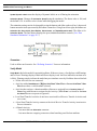
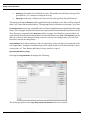
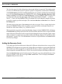
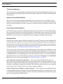
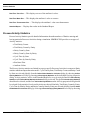
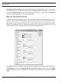
The Activity Browser can be used to search for specific Processes or Activities. There are three search
criteria: Activity name, Activity type, or Activity icon. Each can be used individually or in combination.
Search criteria that are combined are combined using “and” logic. The asterisk (*) can be used as a
wildcard for name searches. The asterisk can go at the beginning of the search string, the end of the
search string, or both. Wildcards cannot be used in the middle of a search string. Select Ignore Case
to perform case insensitive searches. Selecting Find Activity finds the first Activity in the model
hierarchy that matches the search criteria. Subsequent clicks of Find Activity will continue the search
for the next match.
SIMPROCESS User’s Manual
35
SIMPROCESS Terminology and Menus
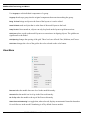
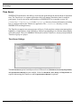
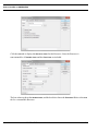
Connector Browser...
Connector Browser... is a feature for navigating among the Connectors. A dialog lists all the Processes
and Connectors contained in the model. Any name preceded by a (+) signifies a hierarchical Process
or a Process Alternative. Double-clicking on the Process or Process Alternative name will expand the
tree diagram, displaying Connectors and Processes underneath. Double-clicking on the Connector
name will bring up the properties of the Connector. Each item has an icon that identifies the item as
a Connector or a Process. Select a Connector and either Edit the Properties of that Connector or Go
To the layer in the model layout where that Connector resides. Expand All expands the complete model
hierarchy, and Collapse All restores the hierarchy to the top level.
SIMPROCESS User’s Manual
36
SIMPROCESS Terminology and Menus
The Connector Browser can be used to search for specific Connectors by name. The asterisk (*) can
be used as a wildcard for searches. The asterisk can go at the beginning of the search string, the end
of the search string, or both. Wildcards cannot be used in the middle of a search string. Select Ignore
Case to perform case insensitive searches. Selecting Find Connector finds the first Connector in the
model hierarchy that matches the search criteria. Subsequent clicks of Find Connector will continue
the search for the next match.
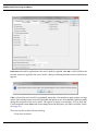
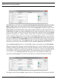
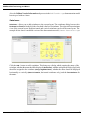
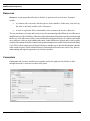
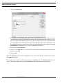
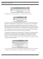
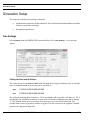
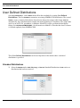
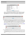
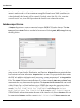
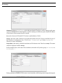
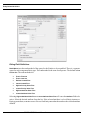
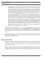
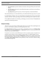
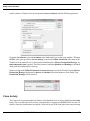
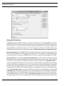
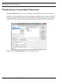
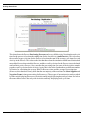
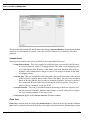
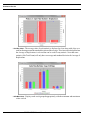
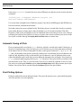
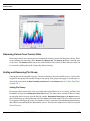
Model Search...
Model Search is a quick way of searching by name for items within the model. The Model Search dialog
has three areas: Search Items, Search Criteria, and Search Results.
SIMPROCESS User’s Manual
37
SIMPROCESS Terminology and Menus
Search Items
has nine check boxes: Process or Activity, Entity Type, Resource, Resource Downtime,
Resource Shift, Global Attribute, Background Text, Connector, or Any (default). The other items become
available for selection when Any is deselected. Model Search searches the names of the selected Search
Items based on the options set in Search Criteria. Enter the string to search for in the text field of Search
Criteria, then select how to compare the string entered with the names of the selected Search Items.
The options are Equals, Starts With, Ends With, or Contains. Select Ignore Case to perform a case
insensitive search. Once the Search Criteria has been set, click the Find... button to perform the search.
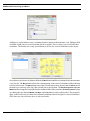
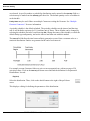
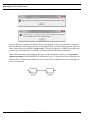
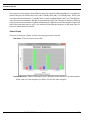
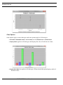
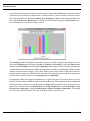
Search Results displays the items found. The type of each item found (Process or Activity, Entity Type,
Resource, Global Attribute, Background Text, or Connector) is identified by an icon to the left of the
name. Process, Activity, or Entity Type items display a scaled down version of their assigned icons.
Resource, Global Attribute, Background Text, or Connector display an icon based on the legend to
the right of the list. The example below shows a search on the CallCenter.spm demonstration
model. The search was a case sensitive search for any names containing Type. Four background text
items, four activities, three entity types, one global entity attribute, and three connectors were found.
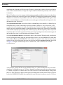
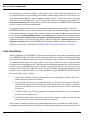
Selecting an item will cause the Edit... button to activate. The properties of the item can be edited by
clicking the Edit... button or by double-clicking an item. The Go To button will activate if the item
selected is a Process or Activity. Selecting Go To will take you to the level of the model where that
item is located.
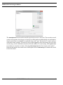
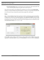
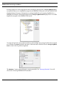
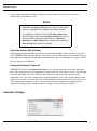
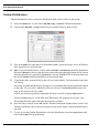
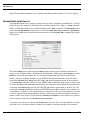
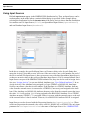
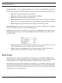
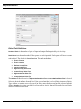
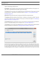
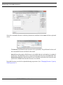
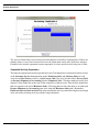
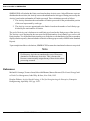
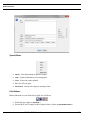
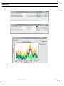
Expression Search...
Expression Search is a quick way of searching for the existence of expressions or for expressions that
contain specific text. Searching for text can also include replacing text. As with Model Search, the
Expression Search dialog has three areas: Search Items, Search Criteria, and Search Results.
SIMPROCESS User’s Manual
38
SIMPROCESS Terminology and Menus
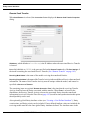
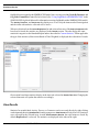
Search Items has seven check boxes: Process or Activity, Entity Type, Entity Instance, Resource, Function,
Model,
or Any (default). The other items become available for selection when Any is deselected.
searches the expressions of the selected Search Items based on the options set in
Search Criteria. To find items that have expressions no matter what the text of the expressions, leave
the Search For field empty. (Note that if the Search For field is empty, items that have Expressions stored
in files will be located.) To search for specific text in expressions, enter the search text in the Search
For field. All searches are “contains” searches. That is, there is a match if the text in the Search For
field is contained within any line of an expression. Select Ignore Case to perform a case insensitive
search. If the Replace With field is not empty, the text in the Search For field found in expressions will
be replaced with the text in the Replace With field. There is no undo for replace actions. Also, replace
actions are case sensitive only. Selecting Ignore Case will empty and disable the Replace With field.
Expressions stored in files are not included in searches when the Search For field contains text.
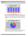
Expression Search
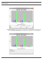
Once the Search Criteria has been set, click the Find... button to perform the search. Search Results
displays the items found. The type of each item found (Process or Activity, Entity Type, Resource,
Function, or Model) is identified by an icon to the left of the name. Process, Activity, or Entity Type
items display a scaled down version of their assigned icons. Resource, Function, and Model display
an icon based on the legend to the right of the list. The example below shows a search on the
CallCenter.spm demonstration model. The search was a case insensitive search for any
expressions containing type. Four Activities, three Resources, and one Function were found.
Selecting an item will cause the Edit... button to activate. The properties of the item can be edited by
SIMPROCESS User’s Manual
39
SIMPROCESS Terminology and Menus
clicking the Edit... button or by double-clicking an item. The Go To button will activate if the item
selected is a Process or Activity. Selecting Go To will take you to the level of the model where that
item is located.
Metadata Search...
is a quick way of searching for the existence of metadata or searching for specific
metadata. See “Entering Metadata” for Metadata Search instructions.
Metadata Search
Properties…
Selecting Edit/Properties… will bring up the Properties dialog box for the selected item. This has the
same effect as double-clicking on it. Use this menu item most often when you want to edit Hierarchical
Processes, since double-clicking on them will show their internal structure and not bring up their dialog
box.
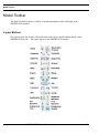
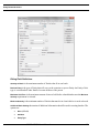
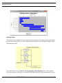
Layout Menu
Size...
presents a dialog that allows you to specify the size (in pixels) used in the drawing of model
layouts. The layout is the area on the screen where models are built and displayed. The default setting
is a width of 925 and height of 575. The size can be changed for the current session, saved and used
for subsequent SIMPROCESS sessions, saved with the current model layout and always used to display
it, or saved and used with all layouts in a model. Each time a layout is displayed, its stored size will
be used. The session setting will be used if there is not a stored size. The current size of the active layout
Size...
SIMPROCESS User’s Manual
40
SIMPROCESS Terminology and Menus
is displayed at the bottom of the dialog. Default is displayed if the active layout size is the current
session’s default layout size; otherwise, the actual dimensions are displayed.
Enforce 4:3 Aspect Ratio defaults to being not selected. If Enforce 4:3 Aspect Ratio is selected, the ratio
of width to height must be 4 to 3. Selecting Enforce 4:3 Aspect Ratio will cause the default width of
925 and height of 575 to change to 928 and 626 respectively since 925 and 575 do not conform to the
4 to 3 ratio. This ratio is enforced whenever a change is made to the height or width. For example,
if the height were changed to 712, the width would automatically change to 952, and the entered value
of 712 would change to 714. Thus, both values are updated to the next higher values that meet the 4
to 3 ratio.
Width
is the width of the layout in pixels (640 minimum).
Height
is the height of the layout in pixels (480 minimum).
Default Setting either saves the entered width and height as the session default (Set as Default) and causes
this size to be saved for use in future SIMPROCESS sessions, or it removes the saved session setting
(Remove Default Setting) so that future SIMPROCESS sessions will use the 925 by 575 size. The setting
used for the remainder of the current SIMPROCESS session (unless changed again via this dialog)
will be the one specified here.
Apply to Current Model
enables the following four options:
•
Current Layout Only applies the entered values only to the active layout. The specified size of
the current layout will be stored with the model when the model is saved.
•
All Layouts in Current Model stores the entered values with all layouts in the active model so that
they become permanent (if the model is saved).
•
Clear Current Layout Setting removes a previously specified layout size for the current layout,
so that the layout is subsequently redrawn (when necessary) using the current session layout size.
SIMPROCESS User’s Manual
41
SIMPROCESS Terminology and Menus
•
Clear All Layout Settings removes stored layout sizes for all layouts of the current model. The
layouts will subsequently display using the current session layout size.
The current session setting is only changed if no checkboxes are selected or if the Default Setting
checkbox is selected. Each time a layout is displayed, if a layout size is specified in the model, that
size will be used; if none is found, the current session setting will be used instead.
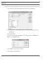
Pools...
Pools... allows the addition of pools to the current layout. (Pools are for display purposes only and have
no impact on the simulation.) The pools dialog has two tabs: Horizontal and Vertical. On the left side
of each tab is a tree view of the pools. The right side has a miniature view of the current layout. Both
horizontal and vertical pools can be on the same layout. The example below shows a modified version
of the demonstration model, Add Vendor.spm.
Click the Add... button to add a pool. This brings up a dialog which contains the Name of the pool, the
Layout Size, the Size and Location of the pool, the Font Attributes for the name, and the Line Attributes.
SIMPROCESS User’s Manual
42
SIMPROCESS Terminology and Menus
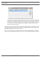
Edit the properties to set the appropriate name and display characteristics. The Layout Size is given
for convenience since the size of a pool should not be larger than the size of the layout. In Size and
Location specify the Width and Height of the pool. The X and Y values specify where the upper left corner
of the pool will be located. So an X of 0 and a Y of 0 means the upper left corner of the pool will be
located in the upper left corner of the model’s frame. The X and Y values must take into account the
Width and Height values. For example, if the Width in above example remains at 1300 and the Height
remains at 575, then X and Y must both be 0 since any value larger than 0 would place the pool outside
of the layout. If 10 is entered for Y the following error displays.
In the Add Vendor.spm demonstration model the following two pools are defined.
SIMPROCESS User’s Manual
43
SIMPROCESS Terminology and Menus
When a pool is selected the Edit, Copy and Remove buttons enable. If a pool is deleted using the Remove
button, it can be restored with the Undo button. The Add Lane button also enables when a pool is selected.
Multiple lanes can be added to a pool. When Add Lane is selected the lane properties display. These
properties are similar to the swimlanes defined in the Layout menu option Swimlanes... (See
“Swimlanes...,” beginning on page 47 for a description of these properties including assigning
OrgModel Nodes.) The difference is the Lane properties include Lane Size. Within Lane Size the Maximum
Size is based on the Height of the pool for horizontal pools and is based on the Width of the pool for
vertical pools. For example, the Height of the Add Vendor pool is 400 so the Maximum Size of the first
lane defaults to 400.
SIMPROCESS User’s Manual
44
SIMPROCESS Terminology and Menus
If a Size is entered that is greater than the Maximum Size, an error will appear when OK is selected.
Note that if only one lane is added to a pool, the size of the lane will match the Height of the pool (or
Width for vertical pools) no matter what value is entered for Size. The Add Vendor.spm
demonstration model has two lanes defined for the Add Vendor pool.
SIMPROCESS User’s Manual
45
SIMPROCESS Terminology and Menus
When a lane is selected, the Edit Lane and Remove Lane buttons enable. The Add Lane and Copy Lane
buttons will only enable if there is still space available for another lane (the new lane’s Size can be
at least 50). In the example below Add Lane and Copy Lane are not enabled since the Size of each lane
is 200, which sums to 400, the Height of the Add Vendor pool.
When OK is selected the pools display in the model.
SIMPROCESS User’s Manual
46
SIMPROCESS Terminology and Menus
Also, the Validate Vendor Information subprocess in the Add Vendor.spm demonstration model
has one pool with two lanes.
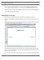
Swimlanes...
Swimlanes... allows you to add swimlanes to the current layout. The swimlanes dialog has two tabs:
Horizontal and Vertical. On the left side of each tab is the list of swimlanes. The right side has a miniature
view of the current layout. Both horizontal and vertical swimlanes can be on the same layout. The
example below shows a modified version of the demonstration model, Human Resources.spm.
Click the Add... button to add a swimlane. This brings up a dialog which contains the name of the
swimlane, whether the name should be displayed (Show Name), whether an OrgModel Node (Org Node)
should be assigned to the swimlane (Assign OrgModel Node), whether the name should be displayed
horizontally or vertically (Name Orientation, horizontal swimlanes only), and the Font Attributes for
the name.
SIMPROCESS User’s Manual
47
SIMPROCESS Terminology and Menus
Edit the properties to set the appropriate name and display characteristics. Assign OrgModel Node is
not enabled if there are no OrgModels assigned to the SIMPROCESS model. (See the SIMPROCESS
OrgModel Manual for more information on creating OrgModels and assigning OrgModels to a
SIMPROCESS model). When enabled and selected, Assign OrgModel Node displays a tree view of the
OrgModels assigned to the SIMPROCESS model.
To assign an Org Node, select a node from the tree and click OK. Once an Org Node has been assigned
to a swimlane, the Name field takes the name of the node and is disabled. Deselect Assign OrgModel
Node to remove the Org Node assignment.
The Metadata... button opens a dialog for entering metadata. See “Entering Metadata” for a full
discussion of entering SIMPROCESS metadata.
SIMPROCESS User’s Manual
48
SIMPROCESS Terminology and Menus
Adding a second swimlane causes a swimlane border to appear in the miniature view. Adding a third
swimlane would cause a second swimlane border to appear. There is always one less border than
swimlanes. The borders are evenly spaced down (or across for vertical swimlanes) on the layout.
Once there are at least two swimlanes defined, the Move button and the two buttons below the miniature
view activate. The Move button allows the rearrangement of the order of swimlanes without having
to delete and recreate. The Move button causes the selected item to move down in the list. Move causes
the item to go to the top of the list if the selected item is the last item. The Border Properties and Lane
Widths buttons change the look of the borders and the widths of the swimlanes. Border Properties brings
up a dialog that sets the Line Width, Line Style, and Line Color for each of the borders. The properties
apply to the borders top to bottom for horizontal swimlanes and left to right for vertical swimlanes.
Since there are only two lanes, there is only one border.
SIMPROCESS User’s Manual
49
SIMPROCESS Terminology and Menus
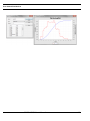
The Lane Widths button changes the widths of the swimlanes. The swimlane defaults to evenly spaced
widths. Each swimlane will be 50% of the layout if there are two swimlanes. The dialog allows you
to enter relative percentages for all or some swimlanes. Entries are not required for each swimlane.
The minimum swimlane width is 5% of the layout. Swimlanes that do not have an entry will be evenly
spaced across the remaining area of the layout. The Current Unassigned Lane Width Maximum Percentage
shows the maximum value that can be assigned to a lane. As-Is Process for Staffing is assigned 50%
of the layout area in the example below. This means 50% of the layout area is left for People Soft HR.
The Clear Widths buttons removes all swimlane width assignments.
The image below shows the application of the border properties.
SIMPROCESS User’s Manual
50
SIMPROCESS Terminology and Menus
When OK is selected on the Swimlane Properties dialog, the swimlanes are drawn on the model layout.
Note that swimlane borders or titles may not be edited by clicking on the layout. All edits must be
done from the Swimlane Properties dialog.
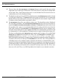
Set Traversal Order...
Set Traversal Order... is used to set the order in which Processes on the current layout will be traversed
when printing or exporting a model. The traversal order can be set for any layout which has two or
more Processes. Since printing or exporting a model requires traversing the whole model, the traversal
order of each layout governs the order of the printing or exporting. The default traversal order for a
layout is the order in which Processes were added to the layout. However, the default order of Processes
on a layout may not be the logical order. In other words, it may make more sense for layouts to be
printed or exported in a different order than the default order of each layout.
Important: The traversal order, whether default or user-defined, only impacts printing, exporting, and
Process numbering. (See “View Menu” on page 56 for information on Process numbering.) It has no
bearing on the simulation flow.
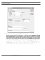
This menu item (which is also located on the contextual menu for a layout) displays a dialog that allows
the order to be changed. For example, consider the Human Resources demo model displayed above.
Below is the current order for that model.
SIMPROCESS User’s Manual
51
SIMPROCESS Terminology and Menus
For each set of as-is and to-be Processes, the layout shows Staffing first followed by Recruitment,
then Hiring. However, when printed or exported, for the as-is Processes, Recruitment will print or
export before Staffing, and, for the to-be Processes, Hiring will print or export first when it should
be last. When a Process is selected, the Move Up and Move Down buttons enable. These buttons allow
the Processes to be given a different traversal order.
When OK is selected, if the traversal order in the dialog is different from the default order, the order
is stored as a part of that layout. Again, even though the traversal order is now different, this change
in the traversal order has no impact on model simulation.
SIMPROCESS User’s Manual
52
SIMPROCESS Terminology and Menus
Selecting Default Order will remove any user-defined ordering for the layout and return the traversal
order to the default order. If Apply to All Layouts is selected when Default Order is clicked, all user-defined
ordering in the model is removed.
Background Color
Current Layout
All Layouts
changes the background color of the visible layout to the selected color.
changes the background color of all layouts in the active model to the selected color.
Align…
Align...
Top
aligns the tops of the selected objects.
Bottom
Left
aligns a number of selected objects according to various criteria.
aligns the bottoms of the selected objects.
aligns the left sides of the selected objects
Right
aligns the right sides of the selected objects
SIMPROCESS User’s Manual
53
SIMPROCESS Terminology and Menus
Center (Vertical)
aligns the centers of the selected objects along a vertical line.
Center (Horizontal)
aligns the centers of the selected objects along a horizontal line.
The screen shots below show the effect of using Align before and after aligning the horizontal centers:
Distribute…
distributes three or more selected objects so that they are equally spaced, vertically,
horizontally, or circularly.
Distribute...
SIMPROCESS User’s Manual
54
SIMPROCESS Terminology and Menus
The screen shots below show the results of using Distribute on some unequally spaced objects.
Before using Distribute:
After using Distribute:
Distribute Pads
Pads added to a Hierarchical Process can be spaced evenly by selecting Distribute Pads. Although
intended for the Hierarchical Process, this menu item can be used for any Activity or Process.
Group combines multiple objects into a group. All normal editing operations that can be done on an
individual object can be done on the group. This can be useful when the model is divided into logical
sections. A section can be grouped and then moved with respect to the other sections. A group can
be cut from the layout, or copied and pasted to create an identical group.
SIMPROCESS User’s Manual
55
SIMPROCESS Terminology and Menus
Use Ungroup to edit individual components of a group.
Ungroup
breaks up a group into the original components that went into making the group.
Bring To Front
brings an object to the front of the layout so it can be edited.
Send To Back
sends an object that is at the front of the model layout to the back.
Snap To Grid.
Once turned on, objects can only be placed on the layout at grid intersections.
Grid Lines places a grid on the model layout as a convenience in aligning objects. The grid has no
significance to the model.
Grid Spacing
Grid Color
changes the spacing of the grid. Three levels are offered: Fine, Medium, and Coarse.
changes the color of the grid to the color selected on the color button.
View Menu
Descend
Ascend
takes the model down one level in the model hierarchy.
takes the model one level up in the Process hierarchy.
Go To Top
takes the model to the top of the Process hierarchy.
Show Process Numbering is a toggle that, when selected, displays an automatic hierarchical number
for each Process in the model. Numbering is off by default for new models.
SIMPROCESS User’s Manual
56
SIMPROCESS Terminology and Menus
The number is purely for documentation purposes and has no impact on a simulation. Processes on
the top layout are numbered 1, 2, 3, etc. Processes contained in the Process numbered 1 are numbered
1.1, 1.2, 1.3, etc. The numbering continues to the lowest level of the model and is based on the traversal
order of the processes on each layout. The traversal order is the order that Processes were added to
a layout (default order) or a user-defined order (see “Set Traversal Order...” on page 51).
The number can display in two places, on the Process icon as a part of the Text Block and as a part
of the Text Label that displays when the layout of the Process is viewed (see “Labeling with Text Blocks”
on page 84). The number displays as a part of the Text Block if Show Text is selected on the Text Block
tab of the Process properties, and the number displays as a part of the Text Label if Add Text Label,
which is located below Show Text, is selected.
The number displays in line one and will precede any text entered in Line 1 Text. The General tab of
the Process properties dialog contains the Use Text Block checkbox. When selected, the contents of
the Text Block are used as the name of the Process. The Process number, even when displayed, is not
a part of the Text Block properties so it will not be a part of the Process name. The example below
shows the Human Resources demonstration model with Process numbering displayed. In this example
Line 1 Text was empty for each Process so the number is the only item displayed in the line 1 location.
SIMPROCESS User’s Manual
57
SIMPROCESS Terminology and Menus
Descending into Process 2 (Recruitment Process in As-Is Process for Staffing swimlane) displays
the number preceding the text in the first line of the Text Label. Note that the Processes within
Recruitment Process are numbered with the number 2 as the first digit.
SIMPROCESS User’s Manual
58
SIMPROCESS Terminology and Menus
Seeds
is used for viewing the random number stream seeds.
Activities
Hide hides the selected Activity. The Activity and its Connectors to it will not be visible on the layout.
Show All
makes all Activities and their Connectors visible.
Show Attached
makes all the Activities that are connected to a selected Activity visible.
By Resource...
allows you to view or edit resource Activity assignments.
By Time Stamp...
By Attribute...
allows you to view or edit Time Stamp key assignments at Activities.
allows you to view or edit Attribute usage at Activities.
Resources
By Activity
allows you to view or edit resource usage by Activity.
Activity Names. These menu items only affect the display of Activity names. The changes are not saved
with the model.
Show All
Hide All
makes all Activity names visible throughout the model.
makes all Activity names invisible throughout the model.
Local shows or hides Activity names based on their individual properties (set with the Properties dialog
Show Name
checkbox). This is the default setting when a model is opened.
Connector Names
These menu items only affect the display of connector names. The changes are not saved with the model.
Show All
makes all connector names visible throughout the model.
Hide All makes
all connector names invisible throughout the model.
Local shows or hides connector names based on their individual properties (set with the Properties dialog
Show Name
checkbox). This is the default setting when a model is opened.
Pad Names
These menu items only affect the display of Pad names. The changes are not saved with the model.
Show All
makes all Pad names visible throughout the model.
SIMPROCESS User’s Manual
59
SIMPROCESS Terminology and Menus
Hide All
Local
makes all Pad names invisible throughout the model.
shows or hides Pad names based on their individual properties (set with the properties dialog
checkbox). This is the default setting when a model is opened.
Show Name
Zoom In magnifies a section of the layout to see more detail. Select Zoom In and click and drag the mouse
to define the area on the layout to zoom.
Zoom Out
is the reverse of Zoom In.
View (1:1)
returns the layout window to its original size.
Refresh
redraws the current screen.
Create Menu
provides an alternative way of creating Activities, rather than graphically dragging and
dropping them from the Layout Toolbar.
Activities
Activities added to a Library can be added to this menu and/or added to the Library Toolbar.
Processes
provides an alternative way of creating Processes.
Processes added to a Library will be added to this menu.
BackgroundText
provides an alternative way of creating static or dynamic labels.
BackgroundGraphic
provides an alternative way of changing the background.
SIMPROCESS User’s Manual
60
SIMPROCESS Terminology and Menus
Define Menu
Entities…
is used for managing Entity Types in the model.
Resources…
is used for managing Resources in the model.
SIMPROCESS User’s Manual
61
SIMPROCESS Terminology and Menus
Resource Downtimes…
Resource Shifts...
is used for managing Resource Downtimes in the model.
is used for managing Resource Shifts in the model (see “Resource Shifts”).
Distributions... is used for managing customized Standard, Tabular, and Auto Fits Distributions. Once
a Distribution is defined, it can be used throughout the model without the need to redefine the parameters
of the distribution. (See “User Defined Distributions” on page 118.)
Input Sources... is used to create connections to an external File, Spreadsheet, or Database. Once an Input
Source has been defined, it can be used throughout the model. (See “Input Sources” on page 131.)
Functions… is used for managing Functions (Expressions that return a value). Functions defined here
SIMPROCESS User’s Manual
62
SIMPROCESS Terminology and Menus
can be used throughout the model.
Global Attributes... is used for globally defining attributes for Entity instances, Entity Types, Resources,
Activities, and the Model. See “Introduction to Attributes and Expressions” for more information on
Attributes.
Model Expressions... defines customized Processing for the model at various points during a simulation.
This topic is covered in detail in “Customizing a Model with Attributes and Expressions”.
Time Stamps…
Metadata
manages Time Stamps. Time Stamps can be used as event logs (see “Event Logs”).
contains three sub menu items: Launch Metamodel Editor, Assign Metamodels, and Model
Metadata.... Launch Metamodel Editor opens the SIMPROCESS Metamodel Editor. Assign Metamodels
assigns a SIMPROCESS Metamodel to the active SIMPROCESS model. Model Metadata... is used to
enter metadata at the model level. See the SIMPROCESS Metadata Manual (SIMPROCESS Metadata)
for information on these topics.
OrgModel contains two sub menu items: Launch OrgModel Editor and Assign.... Launch OrgModel Editor
opens the SIMPROCESS Organization and Resource Model Editor. Assign... assigns a SIMPROCESS
OrgModel to the active SIMPROCESS model. See the SIMPROCESS OrgModel Manual
SIMPROCESS User’s Manual
63
SIMPROCESS Terminology and Menus
(SIMPROCESS Organization and Resource Models) for information on these topics.
Templates defines and edits Templates. This option also allows saving templates to a Library or loading
a new Library. See “Reusable Templates and Libraries”.
provides a place to document the model. See “document Subdirectory” for
information on customizing the headings.
Model Description…
Simulate Menu
Run Settings…
Run Settings
tab is used to set the run options for the simulation. (See “Run Settings” on page 137.)
Cost Periods tab defines cost periods for Activity based costing calculations. (See “Setting Up Cost
Periods” on page 222.)
SIMPROCESS User’s Manual
64
SIMPROCESS Terminology and Menus
Debug Traces tab defines trace files of entity actions for debugging purposes. (See “Debug Traces”
on page 139.)
Expression Options tab offers options for the OUTPUT statement and the BREAKPOINT statement.
(See “Expression Options” on page 140.)
Time Server tab allows the simulation time to be managed by the SIMPROCESS TimeServer. (See
“Time Server” on page 142.)
Remote Transfer tab specifies the port to use for Remote Receive Transfer Activities. (See “Transfer
Activity” on page 166.)
Random Numbers tab specifies the type of random numbers active for the simulation. (See “Random
Number Generation” on page 116.)
Animation Settings…
Show Clock
turns the simulation time clock on or off while the simulation is running.
Show Counts. If Show Counts is turned on, each Activity or Process may display one or more numbers
above its icon and, optionally, vertical bars representing the numbers. All Activities have the option
to display Activity Count. Activity Count (and all other counts) can be turned off at each Activity or
turned off for all Activities by using the Preferences (page 29). The number displayed is based on the
Activity type.
•
•
•
Generate Activities show the number of Entities generated.
Dispose Activities show how many Entities have been disposed.
All other Activities and Processes show how many entities are in that Process or Activity.
Some Activities can also display the number of Entities waiting for Resources (Wait Count), the number
of Entities holding for a condition (Hold Count), and the number of Entities processing (Processing
Count). See “Setting Activity Count Options,” beginning on page 87 for more information.
Show Entities turns the display of Entities on or off during the animation. Showing Entities assists with
visualizing the work flow.
SIMPROCESS User’s Manual
65
SIMPROCESS Terminology and Menus
Update Dynamic Labels
turns the display of dynamic labels on or off during the animation.
Animation Speed.
Changes the Animation Speed during the simulation. The fastest value is 100, and
the default is 20. A smaller value is better while debugging the model.
The animation setting can also be changed by using the buttons and slider on the tool bar. A depressed
button means the item represented by the button is turned on. Going from left to right, the buttons are
Animation On, Show Clock, Show Entities, Show Counts, and UpdateDynamicLabels. The slider is for
Animation Speed. The final button displays the post simulation animation controls. (See “Post
Simulation Animation” on page 215.)
Scenarios...
Used to define run Scenarios. See “Defining Scenarios” for more information.
Verify Model
Verify Model checks the model for potential problems. If there are issues, a list displays with Warnings
and/or Errors. Warnings display in black and Errors display in red. An Error indicates a run time error
is likely. Warnings simply indicate the model may not simulate correctly. Problems detected include
• All the Activities are not connected.
• Activities with a Rank Method of Highest Attribute Value First or Lowest Attribute Value
First do not have a valid Attribute selected.
• Activities that can have a duration and have Resources assigned have a Duration Value of
•
•
•
None along with Resources assigned to the Activity. (When None is selected for the Duration Value Resource requests are ignored.)
Local Send Transfer Activities do not have associated local Receive Transfer Activities and
vice versus.
A local Send Transfer Activity connects with a local Receive Transfer Activity in an inactive
Process alternative.
A Branch Activity
has more than one Otherwise connector
has more than two outgoing connectors when branching on a Boolean attribute
SIMPROCESS User’s Manual
66
SIMPROCESS Terminology and Menus
has more outgoing connectors than Entities defined when branching on Entity Type
has two outgoing connectors branching on the same Entity Type
has one or more outgoing connectors with no Value set when branching on Smallest
Value or Largest Value
•
has branch probabilities that do not sum to 1.0 when branching on Probability
A Gate Activity
has Release Threshold selected with Release Quantity of 0
•
•
has an invalid Batched Entity (only checked if Batch Entities is selected)
A Join Activity has an undefined Family Name
An Assemble Activity
has no Component Entities
•
•
•
•
has an invalid Assembled Entity
A Synchronize Activity has no Input and Output Pads
A Batch Activity has an invalid Batched Entity
A Transform Activity has an invalid Output Entity
A Generate Activity
•
does not have one and only one exiting Connector with Generated Entity specified
A Split Connector has an invalid Output Entity
has an invalid Default Entity
If Verify Model on Run is selected in the Run Settings, verification is done automatically when a
simulation starts. A notification of any problems found will be displayed along with an option to stop
the simulation (Cancel Simulation).
Selecting an item in the list activates the Go To button and, if the item can be edited directly, the Edit
button also activates. The Go To button closes the verification dialog and goes to the layout of the model
that contains the problem item and highlights the problem item. If Edit is selected, the properties for
the problem item are displayed without closing the verification dialog. If the problem was corrected
the item is removed from the list when the properties dialog is closed.
SIMPROCESS User’s Manual
67
SIMPROCESS Terminology and Menus
Activate Scenarios
When selected, a Scenario can be selected before the simulation starts. See “Running Scenarios” for
more information
Run
Run
verifies the model (if selected) and then starts the simulation running.
Change Model Parameters
This item, available only while running a model which has attributes identified as Model Parameters,
will pause the simulation and allow parameter values to be changed. See “Running a Simulation with
Model Parameters,” beginning on page 110 for more information on Model Parameters.
Pause/Resume
If the simulation is running, it pauses the simulation. If the simulation is paused, it resumes running
the simulation.
Stop
stops the simulation and ends the collection of statistics.
Animation On
Animation On turns animation on or off, but does not turn on animation that is turned off in the Animation
Settings.
SIMPROCESS User’s Manual
68
SIMPROCESS Terminology and Menus
Report Menu
Define Global Statistics Collection sets which statistics are collected during the model execution. See
“Default Performance Measures” on page 243.
View Simulation Results displays selected statistics in a table format with options for saving the statistics
to a file and view the statistics graphically. See “View Simulation Results” on page 229.
Export Results
contains three items: Database..., Spreadsheet..., and Simulation...
•
Database...
•
Spreadsheet... is used to create output spreadsheets. See “Defining and Executing Spreadsheet
is used to create SQL statements to export simulation information and results to
databases. Insert, Update, and Delete SQL statements can be created. See “Defining and
Executing Database Exports” in Part B of the SIMPROCESS User’s Manual for more
information.
Exports” in Part B of the SIMPROCESS User’s Manual for more information.
•
Simulation... exports the results of the current model to a tab-delimited file. The data from all
reports selected for the current model will be written to this file. The file can be opened with
a text editor or spreadsheet.
Display Standard Report allows viewing
reports containing the statistical results of a simulation run.
See “Standard Report” on page 243.
Custom Reports...
manages the model’s Custom Reports See “Custom Reports”.
Scenario Reports...
manages the model’s Scenario comparison reports. See “Comparing Scenarios”.
allows the creation of Gantt charts based on the results of the simulation. See
“Activity Gantt Chart” on page 206.
Activity Gantt Chart
SIMPROCESS User’s Manual
69
SIMPROCESS Terminology and Menus
Real-Time Plots... sets which real-time plots to display during or after the simulation run. See “Defining
Plots” on page 259.
Custom Real-Time Plots creates plots with multiple values to view during or after the simulation run.
See “Custom Plots” on page 270.
Display Real-Time Plots
selects real-time plots for viewing. See “Displaying Real-Time Plots” on
page 263.
Launch Plot Application opens a blank plot window. Saved plots may then be opened for viewing. See
“Displaying Plots Remotely” on page 263.
Dashboards Defines new dashboards for use with models, or Assigns previously defined dashboards
to a model. See “SIMPROCESS Dashboards”.
Commit to Database saves simulation results in the SIMPROCESS database (SimProcDB). Commit
to Database is described in detail in “SIMPROCESS Database”.
Launch Database Application starts the database application from within SIMPROCESS. The Manage
Results form launches automatically when launching MS Access from this menu item. The Manage
Results form is described in detail in “SIMPROCESS Database”.
Experiment Menu
sets up the experiments to run. The experiments are stored in the file
Experiments.xml. Defining Experiments is described in detail in “Experiment Manager”.
Define Experiments
Run All Experiments
attempts to run every experiment defined.
Run Selected Experiments
attempts to run experiments for which the Selected field is checked.
Run Specific Experiment enters
an experiment name that SIMPROCESS will attempt to run.
Running experiments is described in detail in “Experiment Manager”.
SIMPROCESS User’s Manual
70
SIMPROCESS Terminology and Menus
Tools Menu
OptQuest executes OptQuest optimization from OptTek. See “OptQuest for SIMPROCESS” for more
information.
Remote
has six sub menus.
•
Start Local Dashboard Server
•
•
Start Local Time Server
•
•
Stop RMI Registry
“Displaying Dashboards”
starts the Dashboard Server to run Dashboards locally. See
starts the Time Server locally. See “Time Server” on page 142.
starts the Java RMI Registry. Start SPServer will not activate until the Java
RMI Registry has been started.
Start RMI Registry
stops the Java RMI Registry.
Start SPServer starts SPServer. SPServer must be started for External schedules to operate. See
“Adding an External Schedule”
•
Stop SPServer
stops SPServer.
Repair Cross-References. Cross references are used in SIMPROCESS models to track Entities,
Resources, and Attributes so items cannot be deleted that are in use. Models developed in releases 3.0
through 3.1.1 could have invalid cross references. Recommend running this utility on models
developed in release 3.0 through release 3.1.1. The action is applied to the active model.
Collect Model Metrics displays a list of metrics for the active model. The metrics can be saved to a file.
Metrics include
Model Name
Number of each type of Activity (Delay, Generate, etc.)
Number of Process Alternatives
Number of Entities, Resources, and Plots
Number of each type of Expression
Number of each type of Attribute
SIMPROCESS User’s Manual
71
SIMPROCESS Terminology and Menus
Icon Manager is used to import, export, and manage image files. A single image file can be imported
for use as an icon, or multiple files (such as a directory of image files) can be imported. See “Importing
Graphics Image Files” on page 202.
Manage Background Images is used to import, export, and manage background image files. See
“Background Images” on page 202.
Window Menu
This displays a list of open models. It is used to change the active model.
Help Menu
SIMPROCESS Help displays a list of main help topics. NOTE: On Windows systems SIMPROCESS
Help uses Internet Explorer. To eliminate the need to give permission to run active content, open Internet
Explorer and go to Tools and select Internet Options. Select the Advanced tab and scroll down to the
Security category. Check the option “Allow active content to run in files on MyComputer*”.
SIMPROCESS Manuals opens the SIMPROCESS Getting Started Manual, each part (Part A, Part B, Part
C, and Appendices) of the SIMPROCESS User’s Manual, the SIMPROCESS Metadata Manual, and
the SIMPROCESS OrgModel Manual. These PDF files are the complete documentation set for
SIMPROCESS. They will open using the application designated for PDF files by the platform on which
SIMPROCESS is installed. On Linux systems, there must be a view.properties file as described
for the View button on the Documentation tab of Activity and Process properties dialogs. (See “Common
Activity Input Fields” on page 81.)
System Information displays a dialog that lists the relevant system information. It also includes a Run
GC
button. This button calls Java garbage collection and updates the Java memory information.
About SIMPROCESS displays information about SIMPROCESS, including the version, the copyright,
and technical support information.
SIMPROCESS User’s Manual
72
CHAPTER 2
SIMPROCESS Basics
A SIMPROCESS model contains the following components:
•
Processes
•
Activities
•
Entities
•
Resources
•
Connectors
•
Pads
Processes and Activities represent business operations in a SIMPROCESS model.
SIMPROCESS models can be arranged in a hierarchy, with Processes encompassing other
Processes and Activities.
SIMPROCESS User’s Manual
73
SIMPROCESS Components
SIMPROCESS Components
Processes
A set of Processes can represent the operation of a business at a very high level. This level
represents only an outline of the business Process.
Activities represent the details of business operations. For example, in a mail order fulfillment
operation, when a customer order is received, processing steps might include:
1.
Identifying the customer.
2.
Creating or accessing a customer profile.
3.
Verifying the customer profile against information contained in the customer’s order.
Each of these steps can be modeled as an Activity. Collectively, they comprise a single Process that
might be called “Access/Create Customer Profile.”
The Process construct allows a business Process to be broken down into successively more detailed
layers.
A Process can be (and usually is) composed of other Processes and Activities. Activities cannot be
decomposed.
Activities
SIMPROCESS contains a suite of Activities, each reflecting a different type of action. Actions can
be physical or logical.
Entities
Entities are objects that circulate through the model. They represent things (e.g., parts, deliveries, people)
or information (orders, service requests, etc.) that flow from Activity to Activity. The customer order
is an Entity in the order fulfillment process.
Unlike Processes and Activities, which appear as icons in the model layout, Entities aren’t visible until
a simulation is run. During the simulation, if animation is turned on, they emerge as icons flowing through
the model.
SIMPROCESS User’s Manual
74
SIMPROCESS Components
Resources
Resources are the agents that add value to Entities or perform work at Activities. Examples
include:
•
A customer calls in an order, which requires a clerk to handle it. Order entry is the Activity,
the order is an Entity, and the clerk is a Resource.
•
A truck is required to deliver merchandise to the customer; the truck is a Resource.
The way to minimize cycle time and Activity costs is by experimenting with different levels of Resources
and different costs. The availability of a Resource affects the amount of time it takes an Entity to flow through
the Process. Lack of Resources can be a cause of bottlenecks in a business Process. A customer order might
arrive while two clerks are busy handling other tasks. Order fulfillment is delayed until a clerk becomes
available. The amount of time the customer order spends waiting for an available clerk is shown in the Entity
Cycle Time by State output report as Wait for Resource. Another way to describe this situation is that the
order waited in a queue for the available Resource. Knowing how Resources are used is a key factor in
understanding and improving upon the way a business operates.
Connectors
Connectors link Activities and Processes together and are the paths used by Entities to flow
through the model. Connectors can have delay times.
SIMPROCESS User’s Manual
75
SIMPROCESS Components
Connector Names
A default Connector name (such as Conn44) is assigned. To change the Connector Name, edit the Name
field in the Connector properties.
Displaying Connector Names
The Edit Preferences option, on the Edit menu, determines if names of new Connectors are displayed
in the model. However, individual Connector dialogs have Show Name check boxes that will override
the model default.
The Name field is displayed across the middle of the Connector if Show Name is selected.
Display Properties
The Line Width and Line Style properties control the appearance of the Connector. Defaults for Line
Width and Line Style can be set in the Preferences. See “Preferences” on page 29.
Duration
A Connector defaults to no Duration. Duration can be specified by setting a Travel Time or Distance
Divided By Rate. If using Distance Divided By Rate, a value must be set for Distance and Rate, and
Rate must not be zero. No units are assumed for Distance or Rate. The Units field applies to the
value that results from Distance being divided by Rate.
Note that a Connector Duration affects Entity animation. When no Connectors on a layout have a
Duration, one Entity moves at a time. This is because the Entity movement occurs in zero
simulation time. However, when Connectors on a layout have a Duration, multiple Entities can be
moving at the same time since the movement represents the passing of time. If some Connectors on
a layout have a Duration and some do not, the movement of Entities on Connectors with a Duration
will stop while Entities cross Connectors with no Duration. The Units set for Travel Time or Distance
Divided By Rate also affect the animation of Entity movement. It is recommended (for animation
purposes only) that the Units of the Connector Duration match the Simulation Time Unit on the Run
Settings dialog. (See “Setting the Simulation Time Unit” on page 108.) If the Simulation Time Unit is
different from the Units of a Connector Duration, then it is possible that either the Entities will move
very slowly across the Connector no matter what Animation Speed (page 65) is set or the Entities
will never show up (again, no matter what Animation Speed is set). If animation is not a
consideration, then any value for Units is valid.
Connector Statistics
Collect Connector Statistics and Collect Connector by Entity Statistics are used to request statistics for
the specified Connector. See “Connector Statistics,” beginning on page 256 for more information.
SIMPROCESS User’s Manual
76
SIMPROCESS Components
Connector Start/End
The Start and End tabs allow the Connector to be moved without deleting and recreating the
Connector. The Start tab displays the available starting Pads for the Connector, and the End tab
displays the available ending Pads for the Connector. If Start and/or End has a selection, the changes
are applied when OK is selected. To clear a selection, press the Control key while clicking on the
selected item.
Pads
Pads are small triangular objects attached to Activities and Processes which serve as attachment
points for Connectors. A single Pad can connect one or (possibly) more Connectors. Entities flow
in one direction, entering nodes at input Pads and exiting at output Pads. Three sizes of Pads are
available: small, medium, and large. The Pad size can be changed on the Pad properties dialog, or
by right clicking on the Pad and choosing Pad Size. The size of all the Pads on an Activity or
selected Activities can be changed by right clicking on a selected Activity and choosing Pad Size.
Pads also connect one level of a Process hierarchy to another. Pads can be queueing areas for
Entities waiting for a Resource or condition.
Putting it Together
A SIMPROCESS model shows a business Process as a set of Nodes (Processes and Activities)
connected by Connectors. Entities are generated from one or more Generate Activities, traverse the
model, and finally proceed to a Dispose Activity, where they are disposed. Entities pass through
other Activities such as Delays and Branches.
A model is built by supplying numeric and symbolic attributes to the various Activities and the
Entities that are processed at these Activities. The Resources needed to process the Entities are also
defined.
The end result is a dynamic model of the business Process. Bottlenecks can be seen as they occur
when simulations are run on this model. Reports and statistics may be generated describing the
flow of people, materials, and information and quantifying how Resources are used. The model
may continue to be modified in order to experiment with different scenarios.
A simple model can be built with just three Activity objects: Generate, Delay, and Dispose.
SIMPROCESS User’s Manual
77
SIMPROCESS Components
All models require a Generate Activity to generate Entities and a Dispose Activity to end the
processing of Entities. Delay Activities are used to represent actions.
There are some things that are common to most Activities, such as the Activity name and
Resources required by the Activity. This chapter begins with a discussion of the input fields and
command buttons used to define these items. The remainder of the chapter describes the core
SIMPROCESS Activities in detail, with particular attention devoted to the Generate Activity and
the Entities.
The remaining SIMPROCESS Activities are described in Chapter 4–Activity Modeling Constructs,
beginning on page 146, and in “Explicitly Getting and Freeing Resources” on page 189.
SIMPROCESS User’s Manual
78
Model Toolbar
Model Toolbar
The Model Toolbar is the two columns of buttons running down the left margin of the
SIMPROCESS window.
Layout Buttons
The buttons in the top section of the toolbar are used to place model building blocks on the
SIMPROCESS layout — the central region of the SIMPROCESS window.
SIMPROCESS User’s Manual
79
Model Toolbar
Define Menu Buttons
These buttons perform the same actions as the corresponding Define menu items. (See “Define
Menu” on page 61.)
SIMPROCESS User’s Manual
80
Adding and Editing Activities
Adding and Editing Activities
Adding Objects to the Layout
Begin by adding a Generate Activity to the model. Click once on the Generate Activity button.
Next, point and click on the SIMPROCESS layout. A Generate Activity icon is added at that
location.
Press and hold the Shift key while clicking on the layout to add several activities of the same type,
i.e., Generate. Each time the layout is clicked, a Generate icon is added to the layout. Release the
Shift key before dropping the last icon or click once on the Select tool to deactivate the Generate
button.
Removing Objects from the Layout
Select an object such as an Activity icon from the layout and press the Delete key. Several items
may be removed at one time by drawing a rectangle around the objects and pressing Delete or
selecting Edit/Clear from the menu or the popup menu.
Common Activity Input Fields
Activity Properties dialogs have the following common input fields:
•
Name is the name chosen to identify the Activity. This name appears below the Activity, and
it can be moved on the layout.
•
Icon
•
Comment is a one-line comment about the Activity. This comment appears in the status bar
identifies the graphic icon representing the Activity.
when the Activity is selected. The comment can contain hypertext that use the protocols http,
https, or file (only file:/// is recognized). To include hypertext the full URL must be included
(such as http://www.simprocess.com). The protocol portion (http://, https://, or file:///) is
removed and the remainder of the URL becomes the hypertext. For example if “See http:/
/www.simprocess.com for more information” is entered, “See www.simprocess.com for
more information” is displayed. If specific hypertext is desired include it immediately
following the URL enclosed by parentheses and quotes. Entering “See http://
www.simprocess.com(“SIMPROCESS”) for more information” will display as “See
SIMPROCESS for more information”.
SIMPROCESS User’s Manual
81
Adding and Editing Activities
NOTE: All Comment fields in SIMPROCESS can contain hypertext. If the properties of
Activities, Entities, Resources, Attributes, or Time Stamps are included in Custom Reports
(see “Custom Reports”), and the Comment contains more than one URL, only the first
URL will be active when the Custom Report is saved to a document format (pdf, docx,
etc.).
•
contains a Document... button that opens an edit window for adding
descriptive text about the Activity. (See “document Subdirectory” for information on
customizing headings.) Next to the Document... button is the Metadata... button. The Metadata...
button opens a dialog for entering metadata. (See “Entering Metadata” for a full discussion
of entering SIMPROCESS metadata.) This tab also contains a field for adding a link to a URL
or another document. (See “Export” on page 19.) The View button launches the preferred web
browser if Is URL is selected. If Is URL is not selected, SIMPROCESS assumes the URL is
a file and will attempt to open the file with whatever program is designated to open that type
of file. For Windows, the View button enables when Is URL is selected and the URL/File field
is not empty, or Is URL is not selected and the URL/File field indicates a path (contains
backslashes or begins with ./). The same conditions apply on Linux systems. In addition,
on Linux, the view.properties file must be in the SIMPROCESS working directory,
and the view.properties file must contain valid url.view and file.view
properties. Due to other applications being required, the View button is not guaranteed to work
in every case. (The SIMPROCESS working directory is in the user’s home directory. On Linux
it is typically the directory /home/username/SIMPROCESS where username is the
account user name.)
•
Attributes define custom attributes that the Activity requires. This topic is covered extensively
in “Customizing a Model with Attributes and Expressions”.
•
Expressions allow customized processing for the Activity at various points during a
simulation. This topic is covered in detail in “Customizing a Model with Attributes and
Expressions”.
•
Event Logs
•
Text Block
•
Counts
•
Help
Documentation tab
are used for defining timestamps and recorders.
is a description that appears within the Activity’s icon on the layout.
are used for setting Activity count display options.
displays information about the Activity.
The following tabs and fields are found on most Activity Properties dialogs:
•
defines the Resources required to process Entities arriving at the Activity. The
Entity waits in a queue until the Resource or Resources can be obtained.
Resources
SIMPROCESS User’s Manual
82
Adding and Editing Activities
•
Duration/Value is the amount of time it takes the Activity to process an Entity, once the required
Resources are obtained. Time can be defined as a constant, or as a statistical distribution.
•
Duration/Time Units
specifies the units and measure for duration time in nanoseconds,
microseconds, milliseconds, seconds, minutes, hours, days, weeks, months, or years.
The following buttons are found on all Activity Properties dialogs except Background Text. These
buttons allow the creation of items that are then available throughout the model.
•
New Entity
•
New Resource
•
Entity
•
Entity Type
•
Resource
•
Model
creates new Entity types.
creates new Resource types.
creates new global Entity instance attributes.
creates new global Entity Type attributes.
creates new global Resource attributes.
creates new Model attributes.
Attributes are covered extensively in “Customizing a Model with Attributes and Expressions”.
Naming Activities
Use the Name field to assign a name to an Activity. This name is shown below the Activity icon in
the model if the Show Name checkbox is selected.
SIMPROCESS assigns new Activities a default name. It is a good idea to change this to a name that
is meaningful; one that indicates what occurs at this Activity. Activities can be named just about
anything, as long as the same name is not used twice in the same level of the model hierarchy.
Change the name of an existing Activity by clicking in the Name field and typing the new name.
The contents of the Text Block can be used as the Name by selecting the Use Text Block check box.
The lines of text are appended together with a space between each line to create the Name. When
Use Text Block is selected, the Name field is not editable. The values on the Text Block tab must be
changed to change the Name.
Choosing an Icon
The Icon field identifies the graphical icon used to represent the Activity in the model layout. All
Activity icons are arranged into sets. The set consists of predefined sets and user defined sets. (See
SIMPROCESS User’s Manual
83
Adding and Editing Activities
“Importing Graphics Image Files” on page 202.) The Icon Set field lists the sets of icons available.
The set All lists all icons regardless of set. Every Activity has several icons from which to choose.
The names of the standard icons differ slightly for each Activity, because they include the name of
the Activity.
Point and click on and icon’s name to select it. The icon button on the right shows the default size
of the icon. Click the icon button to see the actual size.
GIF, JPG, and PNG files may be imported and used as custom icons for Activities.
Adding a Comment
Use the Comment field to add a brief comment describing the purpose of this Activity. This field is
optional. Printing Process Documentation or Model Documentation will include comment in the
document. The comment will appear on the status bar when an Activity is selected.
Documenting the Activity
The Document button opens an editor in which descriptive information may be added about the
Activity. The editor opens with a preformatted template which is changeable. (See “document
Subdirectory”.) Print Document text using the SIMPROCESS Print facility.
Labeling with Text Blocks
The Text Block tab adds text to the inside of the icon on the layout.
Text Block labels facilitate understanding of the Activity or Process in relation to the model.
Add descriptive labels to an icon by performing the following tasks:
SIMPROCESS User’s Manual
84
Adding and Editing Activities
1. Click on Text Block tab:
2. Fill in the text. Press Return at the end of a line to create a new line of text. The text will not
automatically wrap when displayed; thus, the text can extend past the border of the icon. Also,
there is no limit to the number of lines of text; however, three lines of text are optimal as the
text may display above and below the icon if more than three lines of text are entered. Text
beyond the horizontal or vertical bounds of the icon can be adjusted by removing text, changing
Font Attributes, resizing the icon, or some combination of all three.
3. Set the desired Font Attributes.
4. Make sure the Show Text box is checked. The text entered is not displayed in the model unless
this box is checked.
5. Click on OK.
Note: The Text Block is best used with blank box icons. Icons with a picture on them may not show
the Text Block properly.
Process properties include an additional option on the Text Block tab. The Add Text Label check box
places a label that contains the text of the Text Block inside each alternative of the Process.
SIMPROCESS User’s Manual
85
Adding and Editing Activities
The lines of text are appended together with a space between each line to create the label. Select the
Properties button to set whether the label should be displayed horizontally or vertically and to set
the Font Attributes of the label.
The label will be centered across the top of the layout when Horizontal is selected, and the label will
be centered along the left of the layout when Vertical is selected. Note that the labels cannot be
resized or moved. Changes can only be made from the Text Block tab of the Process properties
dialog. Defaults for Horizontal or Vertical and the Font Attributes can be set on the Text Label tab of
the Preferences dialog (Edit/Preferences).
SIMPROCESS User’s Manual
86
Adding and Editing Activities
Setting Activity Count Options
The Counts tab allows customizing of the Activity counts.
All Activities will have settings for Activity Count. Display Activity Count turns the display of
Activity Count on and off. (All counts are hidden if Show Counts is not selected. See “Animation
Settings…,” beginning on page 65 for more information.) When selected the Color of the count and
its optional count bar can be specified. If Show Count Bar is selected, a vertical bar will display
showing the relative value of the count. Maximum Bar Height is the maximum value that will be
displayed by the vertical bar. If the count goes above the maximum the actual count value will
display, but the vertical bar will not change.
If an Activity can have a Duration and can have Resources assigned, there will also be the options
which represents the number of Entities waiting for Resources at the Activity,
and Display Processing Count, which represents the number of Entities processing at the Activity. If
the Activity can hold Entities in any type of queue, there will be the option Display Hold Count,
which represents the number of Entities holding for a condition at the Activity.
Display Wait Count,
Below is the Counts tab for a Gate Activity. It has all four options.
SIMPROCESS User’s Manual
87
Adding and Editing Activities
Getting Help
The Help button displays information about the purpose of the Activity and the fields and buttons
on the General tab of the dialog. The other tabs have Help buttons that are specific to that tab.
SIMPROCESS User’s Manual
88
Generate Activity
Generate Activity
Generate Activities create Entities for a model during a SIMPROCESS simulation. Generally, the
first Activity defined in the model is a Generate.
SIMPROCESS generates Entities at the rate defined in the Generate Activity. Entities can be
generated at a constant number and rate, such as a specified interval of time, or according to a
statistical distribution. The schedule of generation can be as simple as one constant rate, or as
complex as dozens of different rates depending on the hour of the day, day of the week, season of
the year, etc.
A Generate Activity can generate one or more types of Entities
Defining a Basic Generate Activity
Click on the Entity pull-down arrow to select the default type of Entity to be generated by this
Generate Activity. The default Entity type can be overridden in each schedule.
Entities may be defined using the New Entity command button on this dialog.
Use the Quantity field to specify the default number of Entities to be generated each time Entities
SIMPROCESS User’s Manual
89
Generate Activity
are released. A specific number or probability distribution can be entered in the Quantity field or a
selection may be made from the Quantity pull-down list. The default quantity can be overridden in
each schedule.
Family Name may be used if there are multiple Connectors exiting the Generate. See “Multiple
Generate Connectors” for more information.
A periodic schedule is the default schedule. The periodic schedule sets the interval and the time
unit. It will default to an interval of 1.0 and time unit of Hours. These defaults can be changed by
selecting the schedule (Periodic1) and choosing Edit. Change the name of the schedule, override the
default Entity type and quantity, and set the interval and time unit with this method.
The Interval field defines the time between Entity generation events. Enter a constant value or a
statistical distribution. Entities are generated at the end of each interval:
For example, assume Customer Orders to arrive at an exponential rate, with an average of 20
arrivals per hour. Click on the Interval pull-down arrow and find the definition for Exponential
Distributions. It reads:
Exp(10.0)
Select the distribution. Then, click on the details button to the right of the pull-down
arrow.
This displays a dialog for defining the parameters of the distribution:
SIMPROCESS User’s Manual
90
Generate Activity
Set the Mean value to indicate an average Entity generation rate of 20 per hour.
Assume that Quantity is 1, meaning that only one Entity is produced at each Entity generation
event:
•
Generate an Entity every 3 minutes to get 20 Entities in an hour (60 minutes).
The View button displays a graphical representation of the distribution:
Stream
identifies the random number stream used to seed the distribution.
More can be learned about statistical distributions and random number streams in Chapter 3,
“Statistical Modeling Constructs,” beginning on page 114.
SIMPROCESS User’s Manual
91
Delay Activity
Delay Activity
Delay Activities, common building blocks found in most models, have two functions: they
represent the passage of time during simulation and define the Resources required to perform a
task. The cycle time of an Entity traversing the model is the sum of the delays it encounters, i.e., the
time spent at the Activities in its path, time spent traversing Connectors, any hold time for a
condition to be met, and the wait time for any Resources.
The Resources tab is where the Resources required to perform an Activity are specified. See
Chapter 5, “Resource Modeling Constructs,” beginning on page 181 for instructions on defining
Resource requirements for an Activity.
Specifying Delay Duration
represents the amount of time required to perform an Activity. This delay time can be
expressed as either a constant value or a statistical distribution.
Value
Time Units determines if the Duration entered is measured as nanoseconds, microseconds,
milliseconds, seconds, minutes, hours, days, weeks, months, or years.
Type the value of the delay duration directly in the field, or select a value from a pull-down list.
A Delay Activity might be defined to represent the task of processing an order. This task takes an
average of 30 minutes to perform, though it may take as little as 15 minutes, or as much as 1 hour.
SIMPROCESS User’s Manual
92
Delay Activity
As shown below, a Triangular distribution is often used to represent the time required to complete a task:
1. Click on the arrow to the right of the Value field to display a list of distributions:
2. Scroll through the list to find the default definition for Triangular distributions. It reads:
Tri(0.0,5.0,10.0)
Select the distribution.
3. Click on the box to the right of the Value field. Fill in the following values: Minimum of 15,
Mode of 30, and a Maximum of 60.
4. Click on View to see what the curve looks like.
5. Click on OK to accept the definition.
SIMPROCESS User’s Manual
93
Delay Activity
6. Select Minutes from the Units field.
See Chapter 3, “Statistical Modeling Constructs,” beginning on page 114 to learn more about these
parameters and the topic of statistical distributions.
SIMPROCESS User’s Manual
94
Dispose Activity
Dispose Activity
A Dispose Activity disposes of Entities when they are no longer needed in the simulation. The
Dispose marks the end of an Entity’s cycle time for the purpose of statistic collection (e.g., cycle
times and counts).
Dispose Activity Properties
The Dispose Activity Properties dialog contains only one unique field: Maximum Entity Count. Use
this field to set a limit to the number of Entities that can be disposed of at the Dispose during a
simulation. The simulation ends if this limit is reached. End a simulation after 1,000 customer
orders are processed by setting Maximum Entity Count to 1,000.
Leaving Maximum Entity Count undefined or setting a value of 0 or “none” indicates that there is no
limit.
SIMPROCESS User’s Manual
95
Defining an Entity
Defining an Entity
A particular type of Entity or a particular instance of an Entity may be referred to in the model.
When an Entity type is referred to, all Entities of a particular type, e.g., customer orders are also
referred. An Entity instance refers to an individual Entity (a single customer order).
Defining Entities in SIMPROCESS defines a type; SIMPROCESS generates instances of that
Entity during a simulation run. Define Entities in the following manner:
1. Click on Define on the SIMPROCESS menu, and then select Entities... from the pull-down
menu or click on the Define Entities button on the Model Toolbar.
2. Click on Add to define a new Entity.
3. Specify the Entity Type Properties:
•
Entity Name identifies the type of Entity. Name can be any unique entity name.
Double-click on the default name supplied by SIMPROCESS, and enter Customer
Order as the Entity Name.
•
Entity Icon is the icon which will represent this Entity during a simulation run. The icon
appears during simulation if the Animation option is on. Click on the downward-pointing
arrowhead next to the Entity Icon field to get a list of different icons to choose from the
currently selected Icon Set.
•
Priority values range from 1 to 100. When Entities contend for the same Resource, the
Entity with the highest priority gets precedence.
SIMPROCESS User’s Manual
96
Defining an Entity
•
Preempt Lower Priority Entities sets whether instances of this type will preempt lower
priority Entities. If true, when an instance of this type reaches an Activity that uses
Resources and there are no Resources available, and the Entity currently using the
Resources is a lower priority Entity, this higher priority arriving entity instance will cause
the lower priority Entity to release the Resources so this Entity can obtain the Resources
and Process.
•
Entity Attributes, Entity Type Attributes, Entity Expressions,
•
Document... opens an editor window into which extensive comments can be entered about
the Entity and the model. This is optional. The Entity document headings can be
customized. (See “document Subdirectory”.)
•
Metadata... opens a dialog for metadata entry. See the SIMPROCESS Metadata Manual
for information on using metadata in a SIMPROCESS model.
•
Comment
and Entity Type Expressions
are used in association with any attributes or expressions defined for this Entity. A choice
can be made to create a new copy of an attribute or evaluate an expression every time
an instance of an Entity is created. Alternatively, one copy of an attribute can be created
or an expression evaluated once for an Entity type and have all instances refer to this
value. Attributes and expressions are discussed in “Customizing a Model with Attributes
and Expressions”.
is used to enter brief text describing the purpose of the Entity.
4. Click on OK when data entry is completed. The defined Entity is added to the table in the Entities
dialog.
5. Add another Entity and name it Shipment. Click on the pull-down arrow next to the Icon field
to get a list of Entity icons.
SIMPROCESS User’s Manual
97
Defining an Entity
The list may be a lot longer than it first appears. Click near the top of the scroll bar to see
more list items. Select GreenDot. Then click on OK. The icon selected will appear on the
button next to the icon list. Clicking the button will bring up a dialog that shows the display
size of the icon. The width and height used during a simulation can be changed. The
minimum for width and height is 10 and the maximum is 100. A default size for Entity
icons can be specified in the Preferences.
SIMPROCESS User’s Manual
98
Defining an Entity
Note that the basic properties of Entities added to the model can be edited directly from the
table. However, changes made in the table are direct changes to the properties of the Entity
and cannot be canceled. Also, the table can be sorted by a particular column by clicking on
the column header. Holding the Shift key while clicking on a column header causes the
table to sort in the reverse order.
Copy the properties of an existing Entity (such as the one just defined) by selecting the Entity in the
table and click on the Copy button. Enter a different Entity Name and make any other changes on the
Entity Type Properties screen, and then click on OK.
Remove an existing Entity by selecting the Entity and clicking on the Remove button. The Undo
button restores Entity definitions that have been removed. Click on Close when Entities are defined.
SIMPROCESS User’s Manual
99
Defining Resources and Processes
Defining Resources and Processes
Resources
The next thing to define in the model are the Resources required to process Customer Order
Entities. To keep things simple, define just one Resource, the clerks needed to process customer
orders.
1. Select Resources... from the Define pull-down menu or click on the Define Resources button
on the Model Toolbar.
2. Select Add to define a new Resource.
See Chapter 5, “Resource Modeling Constructs,” beginning on page 181 for an explanation of the
remaining options and commands, and for more details on defining Resources, including predefined Resource types.
Processes
A SIMPROCESS Process defines Processes hierarchically. In this example, we will define a Process that
indicates how customer orders are handled
Select the Process button from the Model Toolbar and click on the layout.
SIMPROCESS User’s Manual
100
Defining Resources and Processes
Display a dialog for defining the Process. Do this by either:
•
•
Clicking on the Process icon to select it, and then pressing Alt+Enter
Selecting the Process icon, and then selecting Edit from the menu bar, followed by Properties...
Alternative Sub-Processes
A Process may consist of a set of Alternative sub-processes. Each sub-process can represent an
alternative implementation of the Process. This allows the creation of many variations of a Process
and keeps them organized in one place.
Only one sub-process can be active at any point in time. An experiment may be run with
Alternative sub-process 1 active to measure the overall performance of the model. Alternative subprocess 2 can then be run and results compared.
SIMPROCESS defines a single default sub-process when a Process is created. Renaming the subprocess to something more meaningful for the model is accomplished by:
1. Selecting it from the Alternative Sub-Processes list on the Process dialog.
2. Clicking Edit to modify the sub-process definition.
3. Highlighting the existing name and typing over it. For this example, call the sub-process Main.
4. Click on OK.
The new name appears in the Alternative Sub-Processes list and becomes the active sub-process.
SIMPROCESS User’s Manual
101
Defining Resources and Processes
More sub-processes may be added to the Process by clicking on Add and naming the new subprocess. Activate a different sub-process by selecting it from the Alternative Sub-processes list.
Sub-processes may be deleted with the Remove command button and copied using the Copy button.
Click on OK when the Process is defined.
Adding Detail to a Process
Once a Process is defined, define the Activities and Processes that make up the Process.
Right-click on the Process icon and choose Descend to open the layout of the currently active subprocess.
A blank layout is shown, except for two Pads: an input Pad on the left and an output Pad on the right.
If the output Pad is not visible, scroll to the right.
These Pads connect any Processes and Activities at this level of the sub-process to the Activities
and Processes at the next higher level. Once the input and output Pad are connected by Connectors,
Entities flow from level to level.
Activities (and Processes) may be added within the sub-process to detail the tasks being performed.
SIMPROCESS User’s Manual
102
Defining Resources and Processes
NOTE: Make sure the Input and Output Pads are connected on all sub-processes. If this is not
done, Entities will have no path to follow across the Process. Entities entering the Process will
never emerge again.
Master Processes
A hierarchical Process can be designated as a Master Process. If a Process is designated as a Master
Process, any copies of the Master Process pasted within the same model are linked to the Master
Process. Any changes made to the Master Process can be applied to all the copies of the Master
Process. Copies of a Master Process cannot be edited. Select Master Process on the Process
properties to designate a Process as a Master Process.
When OK is selected and there are no copies of the Process, the Process is simply marked as a
Master Process. If there are copies, the copies are updated with all property changes and with any
changes made within the Process (such as addition or deletion of Activities). Copies of a Master
Process can also be updated by right clicking on the Process and choosing Master Process/Update
Copies.
If Master Process on the Process properties is deselected, when OK is clicked the copies of the
Master Process will lose their link to the Master Process. At this point, the copies can be edited and
changed. A single copy can be unlinked from the Master Process by right clicking on the Process
and choosing Master Process Copy/Remove Master Link.
SIMPROCESS User’s Manual
103
Defining Resources and Processes
The contents of a copy of a Master Process can be viewed, but no changes can be made to the
contents. The properties of Activities and Processes within the copy can be viewed but any changes
cannot be saved; however, the properties of a copy of a Master Process cannot be viewed. If
Properties is selected for a Master Process copy, an option to view the properties of the Master
Process will be displayed.
The names of all Activities and Processes within a Master Process copy are modified so the names
are different from the corresponding Activities and Processes in the Master Process. A number is
appended to each name based on the number of the copy. For example, for the first copy of a
Master Process, 1 is appended to each name. The second copy of the Master Process appends 2 to
each name. Any Activity or Process names in the copy referenced in Expressions of the copy are
updated with the new names. Errors may occur if other parts of the Expressions also match names
that were changed. For example, if the System Attribute NumberDisposed is referenced in an
Expression, avoid naming a Dispose Activity “Dispose”. When “Dispose” is changed to
“Dispose1” for the copy, NumberDisposed will be changed to NumberDispose1d.
Process Expressions can be edited by right clicking on the Process and choosing the Expression to
edit. If this is done on a Master Process copy, as with viewing the properties of a copy, an option to
edit the Expression of the Master Process will be displayed.
The active alternative of a Process can be changed by right clicking on a Process. If the Process is a
copy of a Master Process, the alternatives can be viewed but the active alternative cannot be
changed. Changing the active alternative of a Master Process will change the active alternative of
all copies.
If a copy is made of a Master Process copy, the pasted Process will also be a copy of the Master
Process. If a Master Process is cut, the links to the copies will be lost even if the Master Process is
pasted back into the model. A warning is displayed before the cut occurs.
SIMPROCESS User’s Manual
104
Defining Resources and Processes
If a Master Process is deleted, an option will be offered to also delete the copies.
If the copies are not removed, the links to the Master Process are lost and are not restored even if
the deletion of the Master Process is undone. However, if the copies are removed along with the
Master Process, when Undo is selected the Master Process and copies at the same level as the
Master Process are restored with the links intact. Note that if a copy is at a different level of the
model from the Master Process, Undo must be selected at that level for the copy to be restored. The
undo of the Master Process deletion should occur before the undo of any copy deletions at different
levels. If a Master Process and a copy at the same level are to be deleted, only delete the Master
Process and either choose to delete all copies or delete the copy separately.
There cannot be a Master Process within a Master Process. The Master Process option is disabled
for child Processes of a Master Process. Also, if a higher level Process is designated a Master
Process, a warning will display explaining that a child Process is a Master Process and that
continuing will cause the child Process to lose its Master Process designation. If the option to
continue is selected, the child Process does not actually lose its Master Process designation until OK
is selected on the Properties dialog.
A copy of a Master Process cannot be pasted within the original Master Process. This is enforced
even if the copy of the Master Process is embedded in another Process that is being pasted.
SIMPROCESS User’s Manual
105
Defining Resources and Processes
Items in Processes copied from a Master Process will display in the Activity Browser, Connector
Browser, Model Search, Expression Search, Metadata Search, and other display options. However,
those items will not be available for Edit or GoTo. The only exception is, for the Process that is the
actual copy of the Master Process, GoTo is available (unless in an inactive alternative).
Master Processes and copies of Master Processes can be identified visually by selecting Display
in the SIMPROCESS Preferences (page 31). Master Processes will display an
M at the lower left hand corner of the Process icon, and copies of Master Processes will display a C
in the same location.
Master/Copy Badges
SIMPROCESS User’s Manual
106
Simulation Setup
Simulation Setup
Two steps are needed before running a simulation:
•
Set the run time parameters for the simulation. This could include start and end dates or number
of times to repeat the simulation.
•
Set animation parameters.
Run Settings
Select Simulate from the SIMPROCESS menu and then click on Run Settings… to set run time
options.
Setting the Start and End Dates
The values chosen for the Start and End fields determine how long the simulation runs, in calendar
time. A simulated month of processing can be specified as:
Start:
1/1/2014 00:00:00:000:000:000
End:
2/1/2014 00:00:00:000:000:000
This indicates a starting date of January 1, 2014, at midnight, and an end date of February 1, 2014,
at midnight. The simulation terminates as soon as the clock strikes midnight at the end of January
31. The calendar button next to each date field can be used to set the date for that field. The
calendar button causes a graphical calendar to appear. The date selected on the graphical calendar
populates the appropriate date field.
SIMPROCESS User’s Manual
107
Simulation Setup
A time must be entered or the hours, minutes, seconds, nanoseconds, microseconds, and
milliseconds fields default to zero.
NOTE
Remember that Start and End dates for objects in the model,
must be coordinated those with the simulation run dates.
For example, a Generate Activity with Start and End dates
that fall outside of the simulation Start and End dates will not
generate Entities during the simulation. Or, a Resource
Downtime with Start and End dates outside of the simulation
Start and End dates will not be applied.
Run Dates and the Real Calendar
Both Entity generation schedules and Resource downtime schedules can be based on a day of the
week. SIMPROCESS calculates the day of the week, as well as the month, year, and time of day, at
any moment in a simulation. It maps the simulation dates to the real calendar. For example, in 2014
the year begins on a Wednesday.
Setting the Simulation Time Unit
SIMPROCESS allows the Simulation Time Unit to be set, which is the time unit of the simulation
clock. The simulation clock must maintain a constant time unit. The default is Hours. Even though
each individual time unit can be different, those times are converted to the time unit of the
simulation clock. Also, this is important for reducing rounding errors. If the primary delays in the
model are in seconds or less, the time unit of the simulation clock should be set to Seconds or less.
Converting a delay in nanoseconds (or even seconds) to hours could result in rounding errors,
whereas converting a delay in nanoseconds to seconds or less most likely would not.
Animation Settings
SIMPROCESS User’s Manual
108
Simulation Setup
Show Clock
turns the simulation time clock on or off while the simulation is running.
Show Counts. If Show Counts is turned on, each Activity or Process may display one or more numbers
and, optionally, vertical bars above its icon. The items displayed are set on the Counts tab of the Activity
properties. (See “Setting Activity Count Options” for more information.)
• Generate Activities show the number of Entities generated.
• Dispose Activities show how many Entities have been disposed.
• All other Activities and Processes show how many entities are in that Process or Activity.
Show Entities turns the display of Entities on or off during the animation. Showing Entities assists with
visualizing the workflow.
Update Dynamic Labels
turns the display of dynamic labels on or off during the animation.
Animation Speed. Changes the Animation Speed during the simulation. The fastest value is 100, and
the default is 20. A smaller value is better while debugging the model.
SIMPROCESS User’s Manual
109
Running a Simulation
Running a Simulation
Start the simulation running, either by clicking the run icon on the tool bar, or selecting Simulate
from the SIMPROCESS menu bar, followed by Run.
Before starting the simulation, SIMPROCESS does two things:
1. Prompts for saving the latest changes to the model
2. Checks the model for errors.
SIMPROCESS issues informational messages and aborts the simulation if errors are found.
Choose Verify Model from the Simulate menu before running to check the model for errors before
running a simulation.
Running a Simulation with Model Parameters
If the model has User-defined Attributes which were selected as Model Parameters, when the
simulation run is started, SIMPROCESS will prompt for initial values for those Model Parameters.
The Model Parameters are displayed in a table. The column under Parameter gives the name of the
User-defined Attribute. The Value column shows the value the attribute will have at the start of the
simulation run.
To change the value of a Model Parameter, select it in the table. The Description of the selected
parameter will be displayed below the table along with its default value and the mode of its value
(integer, real, etc.)
The next step is to enter the desired value of the Model Parameter in the Value field. If Reset is
pressed, the selected Model Parameter will return to its default value. The Reset All button, under
the Help button, will set the value of all the Model Parameters back to their defaults.
SIMPROCESS User’s Manual
110
Running a Simulation
Creating Model Parameters from User-defined Attributes is covered in “Creating a User Defined
Attribute”.
Model Parameters can be changed during a simulation run by selecting Change Model Parameters
from the Simulate menu.
Running a Simulation that has Processes with Multiple Alternatives
If the model has one or more Processes with multiple alternative sub-processes (see “Alternative
Sub-Processes” on page 101), when the simulation is started SIMPROCESS will prompt for
selection of the active sub-processes.
The Processes with multiple alternative sub-processes are displayed on the left. When a Process is
selected the defined alternatives are displayed on the right. Select the alternative sub-process that
should be active for the simulation. If a Master Process (page 103) has multiple alternatives, the
copies of the Master Process will not be displayed. The selected alternative for the Master Process
will be applied to all copies.
Simply click Run to accept the alternative sub-processes already selected in the model.
Running a Simulation with Model Parameters and Process Alternatives
If a model contains both Model Parameters and Processes with multiple alternative sub-processes,
SIMPROCESS will prompt for both on a single dialog with a tab for each.
SIMPROCESS User’s Manual
111
Running a Simulation
Running a Simulation with Scenarios
If the model has Scenarios defined and Activate Scenarios is selected on the Simulate menu, when
the simulation run is started, SIMPROCESS will prompt for a run Scenario. See “Running
Scenarios” for more information.
Allowable Actions During a Simulation
While a simulation is running, a Process can be descended into to view Entity movement within the
Process hierarchy. Descending into a Process is done by using Descend on the View menu, clicking
the down arrow on the tool bar, right clicking on a Process and choosing Descend, or by doubleclicking on a Process.
To ascend to a higher level of the model hierarchy choose Ascend on the View menu, click the up
arrow on the tool bar, right click on blank area and choose Ascend, or double-click on any blank
area of the model layout. Choose Go To Top instead of Ascend to ascend to the top level of a model.
The Simulate option on the menu bar causes the following options to occur:
•
•
•
•
Pause the simulation
Resume simulation after a pause
Stop the simulation before its scheduled end
Click on Animation Settings to change animation options. The simulation pauses while this
is being done. Changing the animation options using the tool bar does not pause the simulation.
Double click on an Activity icon to bring up its properties dialog. However, any changes made will
not be reflected in the running simulation.
Animation can be recorded for playback after the simulation ends. (See “Post Simulation
Animation” on page 215.)
SIMPROCESS User’s Manual
112
Simulation Results
Simulation Results
There are two options for quickly reviewing output statistics after a simulation run has completed:
View Simulation Results and the Standard Report.
View Simulation Results
Choose View Simulation Results on the Report menu. This displays a dialog that allows the
selection of specific statistics to be viewed in a tabular format. Also, there are options for saving the
results and viewing the results in various chart types. See “Simulation Results,” beginning on
page 229 for more information.
Standard Report
After the simulation run has completed, the Standard Report may be displayed to view output
statistics for the model. From the Report menu bar, choose Display Standard Report.
This will open the Display Standard Report dialog. In the Report Replications list box (if the model
ran for multiple replications), select an individual Replication, the Average of All Replications run,
or the Sum of All Replications run. Typically, the report of interest will be the Average of All
Replications report. Calculate Confidence Intervals is activated if the Average of All Replications
report is selected, which allows selection of 90%, 95%, or 99% confidence intervals for each
performance measure. Select to view the Standard Report with a Text Editor (Wordpad by default),
with a Spread Sheet, or with the Report Viewer, and press the Display Report button to open the
report.
See “Standard Report,” beginning on page 243 for more detail on the Standard Report.
SIMPROCESS User’s Manual
113
CHAPTER 3
Statistical Modeling Constructs
SIMPROCESS allows the analyzing of processes using discrete event simulation. This
means that SIMPROCESS models systems by taking the processes that happen in the real
world and breaking them down into the key events that occur. Parts move to a station in a
factory, are processed, and then move to the next station. If one part goes into a station and
one part comes out, then the most important aspect of modeling the station would be to
capture the processing time (which, in the real world, will vary due to any number of factors) by a statistical distribution.
A statistical distribution is used to give the model the randomness that always occurs in
the real world. Of course, if things in the real world never varied, simulation would not be
needed! Mean-value analysis of your system would suffice. Mean-value analysis is a simple way of predicting system performance by looking only at average rates. Unfortunately,
the real world almost never matches the performance predicted by mean-value analysis,
because statistical fluctuations almost always need to be taken into account.
Expertise in statistics or modeling is not needed to use SIMPROCESS, though; just having
some idea of how things vary is enough. If data shows it usually only takes 5 minutes for a
clerk to process some paperwork, but it can take as long as 15, that is the beginning of a
statistical model of that clerk. Exact answers are not necessary, just general behavior.
Introducing a small amount of randomness through simulation can be all that is needed to
transform a simplistic mean-value analysis into a realistic model.
SIMPROCESS provides a visual flow through the system, in addition to being able to model
SIMPROCESS User’s Manual
114
processes’ statistical nature. It is very difficult to know how people, machinery, deliveries, and
resources are going to interact in a proposed system. SIMPROCESS shows how these interactions
might occur while still in the planning stage. Animation provides valuable insight into how things work
and how they could work.
SIMPROCESS User’s Manual
115
Random Number Generation and Standard Distributions
Random Number Generation and Standard
Distributions
Random Number Generation
SIMPROCESS contains 215 random number streams, each having a different random number seed.
You can view the seeds by selecting Seeds on the View menu.
The purpose of using different random number streams in the model is to control variance. This is
an advanced topic well beyond the scope of this manual. Please refer to texts on statistics and randomness, including Simulation Modeling and Analysis by Law and Kelton (McGraw-Hill).
SIMPROCESS offers two types of random number generation: Legacy and Mersenne Twister. The
Legacy random number generator is the default random number generator. It is the same random
number generator used in CACI’s Simscript product. Mersenne Twister is a random number generator developed in 1997 by Makoto Matsumoto and Takuji Nishimura. The random number generator to use is set on the Run Settings (see “Random Numbers” on page 146).
Standard Distributions
SIMPROCESS includes many standard probability distributions, and you can also create empirical
distributions from your own data. Some of the probability distributions have more than one implementation. SIMPROCESS includes 11 distributions from the Apache Commons Math library (see
commons.apache.org/proper/commons-math/). These distributions include ACM in the distribution
name (see “Statistical Distributions” for a list).
The following paragraphs discuss selecting distributions and provide brief descriptions of some of
the most common standard distributions.
Choosing the Right Distribution for Your Data
It is not always clear which of the standard distributions should be used. Fortunately, simulation
results are usually not highly dependent on the choice of distributions. A distribution with approximately the right shape should be adequate.
ModelFit, which is used with the Auto Fits feature, fits distributions to empirical data. (See “Auto
Fits Distributions” on page 121.)
Common Distributions
Poisson: Used to model the number of arrivals where the quantity within a time frame is known.
Parameter: Mean.
SIMPROCESS User’s Manual
116
Random Number Generation and Standard Distributions
Exponential: Used to model the time between arrivals. Parameter: Mean.
Normal: Bell-shaped curve; avoid when mean is near zero. Also, the normal distribution is not usually a good distribution for service times since service times are usually skewed to the right. Parameters: Mean, Standard Deviation
Lognormal: Can be good distribution for data that is skewed. Parameters: Mean, Standard Deviation
Triangular: Useful distribution for data that has the least amount of time, the most likely time, and
the most amount of time it takes to perform a task. Parameters: Minimum, Mode, Maximum
A complete listing of the statistical distributions available in SIMPROCESS is available in Appendix D. See “Statistical Distributions”.
SIMPROCESS User’s Manual
117
User Defined Distributions
User Defined Distributions
Selecting Distributions... on the Define menu offers three methods for creating User Defined
Distributions. The first, Standard, customizes an existing SIMPROCESS distribution. The second,
Tabular, creates a statistical distribution from discrete data points using a table format. Auto Fit
automatically fits a distribution from sample data at the beginning of a simulation. The sample data
can be in an ASCII file, spreadsheet, or database. ModelFit is used to perform the distribution
fitting. (See Help/About SIMPROCESS... for information on ModelFit.) Note that the Auto Fit feature
is licensed separately from SIMPROCESS.
These User Defined Distributions can be used anywhere in the model where a statistical
distribution is specified.
Standard Distributions
1. Select the Standard tab to Add, Edit, Copy, or Remove Standard Distributions. Undo retrieves a
distribution that has been removed.
SIMPROCESS User’s Manual
118
User Defined Distributions
2. Choosing the Add, Edit, or Copy button brings up another dialog as shown below, where you
type in the Name and distribution:
Name is any non-blank user distribution name. It must be unique across all Distributions,
Input Sources, and Functions.
Select a distribution for modification.
3. Using the distribution text box, either change the parameters of the distribution within the
parentheses or select the details button (three dots). This button opens a dialog containing the
parameter descriptions, e.g., Erlang parameters.
4. To see the PDF (Probability Distribution Function) and CDF (Cumulative Distribution Function) plotted, choose the View button from the dialog shown in Step 3. The PDF is labeled on
the left y-axis, the CDF on the right y-axis.
5. The graph can be saved to a file. To continue, select Close from the graph’s File pull-down
menu.
6. Once the data is entered, choose OK, and the defined User Distribution is added to the list box.
This User Defined Distribution can now be used anywhere in the model where a statistical distribution is specified.
7. To copy an existing User Distribution, select the distribution, choose the Copy button, and you
can enter another Name for the distribution.
8. To remove an existing User Distribution, select the distribution, and choose the Remove button.
9. Choose another tab or the Close button if finished with User Distributions.
SIMPROCESS User’s Manual
119
User Defined Distributions
Tabular Distributions
Tabular Distributions creates a statistical distribution from a table of discrete data points.
1. Select the Tabular tab. Use this tab to Add, Edit, Copy, or Remove Tabular Distributions.
2. Choosing the Add, Edit, or Copy button brings up another dialog as shown below:
3. Type in the Name any non-blank User Distribution name. It must be unique across all Distributions, Input Sources, and Functions.
4. Type is selected from the list box. Choose either a Discrete or Continuous probability distribution
function. If Discrete is chosen, only the exact values indicated in the right column will be chosen
when the distribution is sampled. If Continuous is chosen, SIMPROCESS will interpolate from
the specified Values and the probabilities associated with them.
5. To update the table, point and click on the cell you wish to modify. Type the number in the table
cell directly.
Rows may be added and deleted by clicking on a cell and then choosing the appropriate button
on the right. The row will be added above the one selected. The Erase Cell button causes the
entry in the selected cell to be erased.
A table may also be populated by importing data from a text file using the Import button.
Choose the View button to see the PDF and CDF plotted. The graph can be saved to a file.
Select Close from the graph’s File pull-down menu to continue.
6. Once the data is entered, choose OK, and the Tabular Distribution is added to the list box. This
Tabular Distribution can now be used anywhere in the model where a statistical distribution is
specified.
7. To copy an existing Tabular Distribution, select the distribution, choose the Copy button, and
enter another Name for the distribution.
SIMPROCESS User’s Manual
120
User Defined Distributions
8. To remove an existing Tabular Distribution, select the distribution, and choose the Remove button.
9. Choose another tab or the Close button when the Tabular Distributions are complete.
Auto Fits Distributions
Creating an Auto Fit Distribution
Auto Fits Distributions creates a statistical distribution from external sample data using ModelFit.
1. Select the Auto Fit tab. Use this tab to Add, Edit, Copy, or Remove Auto Fits Distributions.
2. Choosing the Add, Edit, or Copy button brings up another dialog as shown below:
3. Type in the Name any non-blank User Distribution name. It must be unique across all Distributions, Input Sources, and Functions.
SIMPROCESS User’s Manual
121
User Defined Distributions
4. There are three tabs (File, Spreadsheet, and Database) that are used to specify the source of the
sample data. One or more types of data source can be used. However, only one list of sample data
will be fitted. Thus, if more than one data source is used, the data from all selected sources are
combined into one list for distribution fitting.
5. The File tab is used to specify an ASCII file as the data source. Use File Data Source must be selected
to use this type of data source. The Browse button can be used to locate the file. It is recommended
that the file be located in the model’s directory. Note that the file must contain a single column
of numbers with no header and no non-numeric values.
6. The Spreadsheet tab specifies a spreadsheet as a data source. The Spreadsheet can be a Workbook
file or an XML Spreadsheet. Once Use Spreadsheet Data Source has been selected, four fields are
required: File Name, Sheet Name, Starting Row, and Column. The Browse button can be used to locate
the spreadsheet file. Again, it is recommended that the file be in the model’s directory. Enter the
name of the worksheet in the Sheet Name field. Starting Row should have the row number (rows
start with 1) that contains the first value. Column should have the column number (column A would
be column number 1) of the sample data. The data must be in a single column with no empty cells.
The data is read beginning at the Starting Row and continues until an empty cell is reached. Both
Starting Row and Column are distribution list fields. Thus, the Starting Row and Column can be
parameterized (such as Evl(Model.StartingRow) or Evl(Model.Column) where
Model.StartingRow and Model.Column are Model Attributes designated as Model Parameters).
A run-time error will occur if the specified SheetName does not exist. Also, if the spreadsheet is
a Workbook and a cell is read that contains a formula, the formula is evaluated and the value
returned. Note that not all spreadsheet formula functions are supported. A run-time error will occur
if an attempt is made to read a cell that contains an unsupported formula. In an XML Spreadsheet,
the value calculated by the formula will be returned if it already exists in the file; if not, a runtime error will result. Thus, in an XML Spreadsheet the formula is not evaluated at run-time.
SIMPROCESS User’s Manual
122
User Defined Distributions
7. The Database tab is used to specify an SQL database as the data source. Use Database Data Source
must be selected to use this type of data source. Two items are required: Properties File and SQL
Query. Properties File must contain the database location/connection information. It is the name
of the properties file that contains the JDBC url and driver information and, if necessary, username
and password. This file must be located in the model’s directory. SQL Query must contain the query
that returns the sample data. The query can be parameterized by using model attributes. For
example, "Select TIME_VALUE From TimeTable" can be changed to "Select
Model.TableColumn From TimeTable". In this example, Model.TableColumn is a
STRING Model Attribute that contains the name of the column to read. Note that if the query
returns multiple columns, only the first column will be read for sample data.
SIMPROCESS User’s Manual
123
User Defined Distributions
8. Below the data source section of the dialog are two checkboxes: Set Default Type and Set Default
Bounds. These checkboxes allow "hints" about the sample data to be passed to ModelFit.
Information about the sample data can be useful in obtaining a proper distribution fit. If Set Default
Type is selected (default), then either Continuous (default) or Discrete can be selected. For
example, sample data representing time between arrivals is usually Continuous, whereas sample
data representing number of arrivals is usually Discrete. If Set Default Bounds is selected, then
the lower and upper bounds can be set and passed to ModelFit. Enter Lower Bound Value contains
two selections: -Infinity and 0.0. Enter Upper Bound Value contains one selection: Infinity. Other
numeric values can be used as bounds by typing the values in the appropriate field. For instance,
if the sample data represents task times, then there could be a minimum and/or maximum time
to perform the task. Thus, the fitted distribution should reflect those times. In the example below,
5 is the lowest possible value that the fitted distribution should return. This means the task
represented by the sample data has a minimum completion time of 5 (minutes, hours, etc.). Note
that if neither checkbox is selected, then no information about the sample data is passed to
ModelFit.
SIMPROCESS User’s Manual
124
User Defined Distributions
9. When selected, Always Execute Auto Fit at Simulation Start, causes the data sources to be read and
the distribution to be fitted every time the model is run. Note that fitting will also occur at the
beginning of a simulation if Always Execute Auto Fit at Simulation Start is not selected and the Fitted
Distribution field is empty (Fit Now has not been executed). An error will occur at simulation start
if distribution fitting is attempted, and the Auto Fit license has not been activated.
10.When On Error Use Default Distribution is selected, the associated distribution becomes enabled
allowing the selection of a distribution to use if an error occurs when distribution fitting is attempted
at simulation start. Select Suppress Warnings to disable any warnings that an error occurred and
the selected default distribution will be used.
11. Stream contains the random number stream (1 - 215) to use when drawing random samples from
the Fitted Distribution.
12. The View Data button reads the data sources and displays a list of the sample data along with
summary statistics. The summary statistics include Number of Samples, Minimum, Maximum,
Mean, Standard Deviation, Median, Skewness, and Coefficient of Variation.
SIMPROCESS User’s Manual
125
User Defined Distributions
Note that if the Spreadsheet data source Starting Row or Column or Database data source SQL
are parameterized, the View Data button will not return data. A parameterized Spreadsheet or Database data source can only be read at the beginning of a simulation. View Data
includes data validation so it can be used to verify the data before a distribution fit.
Query
13. The Fit Now button reads the data sources and calls ModelFit to perform the distribution fitting.
If a good fit is obtained, the Fitted Distribution field displays the results. Note that Fit Now will not
work if either the Spreadsheet or Database data sources are parameterized (see above). Fit Now
includes data and distribution validation so it can be used to verify the data and distribution fit
before a simulation run. The example error below shows that ModelFit created a Uniform
distribution with a negative lower bound. A negative lower bound is not allowed. (See “Statistical
Distributions” for information on distribution requirements.) Also, an error will occur if the Fit
Now button is clicked and the Auto Fit license has not been activated.
14. The Fitted Distribution field contains the results of an Auto Fit. The contents of the field can be
selected and copied, but any changes to the field will not be saved. The details button to the right
of the Fitted Distribution field can be used to view the individual parameters and view a plot of
the distribution. Any changes made to the distribution parameters on the detail dialog will not be
saved.
SIMPROCESS User’s Manual
126
User Defined Distributions
15. ModelFit Alternatives contains alternative distribution fits for the sample data. An empty list means
that ModelFit determined that there were no acceptable alternatives. To use an alternative
distribution, either select the distribution then click the Select Alternative button or double click
the desired alternative. The primary distribution will be placed into the list of alternatives, and
the selected alternative will be placed into the Fitted Distribution field. Note that ModelFit
Alternatives are only applicable when using the Fit Now button. It is not possible to select an
alternative when Auto Fit is run at simulation start. The primary distribution will always be used
when Auto Fit is run at the beginning of a simulation. (When running Auto Fit at simulation start,
alternatives generated by ModelFit are written to the simprocess.log file.) To use an
alternative as the primary distribution, Always Execute Auto Fit at Simulation Start must not be
selected.
16. ModelFit Warnings contains warning messages from ModelFit concerning the Fitted Distribution.
These warnings are only displayed here when the Fit Now button is used. The warnings are written
to the simprocess.log file when fitting occurs at simulation start. (The simprocess.log
and file is located in the SIMPROCESS working directory. See “SIMPROCESS Working
Directory”.) None is displayed if there are no warnings. The text of ModelFit Warnings can be
selected and copied using the platform specific keyboard shortcuts.
SIMPROCESS User’s Manual
127
User Defined Distributions
Empirical Distributions
Sometimes ModelFit cannot fit the sample data to one of the SIMPROCESS distributions. This
could be due to the sample data representing a distribution that SIMPROCESS does not support, an
insufficient sample size, or both. When this happens, ModelFit returns an empirical distribution.
The distribution defaults to Continuous unless Discrete is selected in Set Default Type.
An empirical distribution is a histogram based distribution and follows the format of the SIMPROCESS Tabular distribution (page 120). The distribution type displayed in the Fitted Distribution field
will be Emp followed by pairs of cumulative probability and value. The pairs are just comma separated values. In the example below, the first two pairs of cumulative probability and value are
(0.0060, 6.557) and (0.015, 7.715).
SIMPROCESS User’s Manual
128
User Defined Distributions
A table of the values can be displayed by selecting the details button next to the Fitted Distribution
field. By selecting the View button, the dialog allows viewing a Continuous or Discrete (based on
selected Type) plot of the empirical distribution. Note that changes to the Name, Type, or Stream are
not saved.
SIMPROCESS User’s Manual
129
User Defined Distributions
SIMPROCESS User’s Manual
130
Input Sources
Input Sources
operate similarly to distributions in that they return a value. However, the value that
is returned is retrieved from an external source. There are three types of external sources that can be
used as Input Sources: File, Spreadsheet, and Database. Selecting Input Sources... on the Define menu
displays the dialog for managing all three types of input sources.
Input Sources
File Input Source
A File Input Source creates a connection to an ASCII file. The File tab is used for managing File
connections. Use this tab to Add, Edit, Copy, or Remove a File Input Source. Undo retrieves one that
has been removed. Selecting Add, Edit, or Copy brings up the dialog below.
The default Name can be replaced, but the Name cannot contain special characters and must be
unique across all Input Sources, Distributions, and Functions. Either type in the File Name or select
Browse to choose the file. It is recommended that the input file be located in the model’s directory.
A Model Attribute of type STRING that contains the name of the file can be used in the File Name
field. The values in the file should be separated by one or more white spaces (i.e., space, tab, or new
line characters). Although not required, the file will usually contain a single value per line. The
SIMPROCESS User’s Manual
131
Input Sources
input file can contain comments. Any characters that follow double slashes (//) will be ignored.
Spreadsheet Input Source
A Spreadsheet Input Source creates a connection to an Excel compatible spreadsheet file. Two different file types are supported: Workbook files (which usually have the .xls or .xlsx extension)
and Excel XML Spreadsheet files (which usually have the .xml extension). The Spreadsheet tab is
used to manage Spreadsheet connections. Use this tab to Add, Edit, Copy, or Remove a Spreadsheet
Input Source. Undo retrieves one that has been removed. Selecting Add, Edit, or Copy brings up the
dialog below.
The default Name can be replaced, but the Name cannot contain special characters and must be
unique across all Input Sources, Distributions, and Functions. Either type in the File Name or select
Browse to choose the spreadsheet file. It is recommended that the input file be located in the
model’s directory. A Model Attribute of type STRING that contains the name of the file can be
used in the File Name field. Sheet cannot be empty and should contain the name of the worksheet.
As with File Name, a Model Attribute of type STRING that contains the name of the worksheet can
be used in the Sheet field. First Row should contain the value of the first row that has input data. The
evaluation of First Row must result in an INTEGER and must be greater than or equal to one. The
evaluation of Column should also result in an INTEGER greater than or equal to one (column A in
a spreadsheet is column 1). The default behavior is for the row value to be incremented every time
a value is requested from the spreadsheet. (Data is read from the specified worksheet from top to
bottom.) If the value in the cell represented by First Row and Column is to be returned every time a
value is requested, then deselect Increment row for next value.
A run-time error will occur if the specified Sheet does not exist. Also, if the spreadsheet is a Workbook and a cell is read that contains a formula, the formula is evaluated and the value returned.
SIMPROCESS User’s Manual
132
Input Sources
Note that not all spreadsheet formula functions are supported. A run-time error will occur if an
attempt is made to read a cell that contains an unsupported formula. In an XML Spreadsheet, the
value calculated by the formula will be returned if it already exists in the file; if not, a run-time
error will result. Thus, in an XML Spreadsheet the formula is not evaluated at run-time.
Database Input Source
A Database Input Source creates a connection between SIMPROCESS and a database. The Database tab is used to manage Database connections. Use this tab to Add, Edit, Copy, or Remove a Database Input Source. Undo retrieves one that has been removed. Selecting Add, Edit, or Copy brings up
the dialog below.
The default Name can be replaced, but the Name cannot contain special characters and must be
unique across all Input Sources, Distributions, and Functions. Properties File must contain the database location/connection information. Properties File is the name of the properties file that contains
the JDBC url and driver information and, if necessary, username and password. The Properties File
must be located in the model’s directory. (See “OpenDatabase” for more information on Properties
Files.) The Column field must contain the name of a column returned by SQL Query, and SQL Query
must contain the query that returns the input data. The Properties File and Column fields can contain
a Model, Entity Type, or Entity Attribute of type STRING that contains the appropriate information. Also, the query can be parameterized by using Model, Entity Type, or Entity Attributes. For
example, "Select TIME_VALUE From TimeTable" can be changed to "Select
Model.TableColumn From TimeTable". In this example, Model.TableColumn is a
STRING Model Attribute that contains the name of the column to read. (Since the Column field can
be parameterized, Column could also contain Model.TableColumn.) If Execute query for each
SIMPROCESS User’s Manual
133
Input Sources
is selected, SQL Query is executed every time a value is requested from the Database Input
Source and the first value in the result set is returned. If Execute query for each event is not selected
(default), then the next value in the result set is returned.
event
View Data Button
All Input Source types have a View Data button. Once the appropriate fields have been populated
this button will read the specified data source and display the input values. This option will not
work if any of the fields can only be evaluated at run time. For example, if the Spreadsheet Input
Source Column field is specified by an Attribute, View Data will not retrieve data from the spreadsheet.
End of Data Options
Each Input Source type has four options for what to do if the end of the data is reached before the
end of the simulation is reached.
•
•
•
•
Continue simulation with no data
Continue simulation and repeat data
Stop replication
Stop simulation
The default option is Continue simulation with no data. When this option is selected and the data is
numeric, a value of zero will be returned when the end of the data source is reached. If the data contains Strings, an empty string ("") will be returned. Continue simulation and repeat data causes the
data in the Input Source to be repeated until the end of the simulation is reached. Stop replication
stops the current replication but allows the next replication to continue. Stop simulation stops the
current replication and all remaining replications will not execute. Both Stop replication and Stop
simulation display a message when invoked. Note that Input Sources reset to the beginning of the
data at the start of each replication if Reset System is selected in the Run Settings (page 137).
SIMPROCESS User’s Manual
134
Input Sources
Using Input Sources
Defined Input Sources appear in the SIMPROCESS distribution list. Thus, an Input Source can be
used anywhere in the model where a statistical distribution is specified. In the example below,
selecting the distribution list for the Duration Value of the Delay Activity shows that the distribution
list contains one File Input Source (File1), one Spreadsheet Input Source (Spreadsheet1),
and one Database Input Source (Database1).
In the above example, the specified Input Source will return a delay value for each Entity that
enters the Activity. Note that no error will occur if the next value is not a valid number, the end of
the file is reached (File Input Source), there are no more rows with data (Spreadsheet Input Source),
or there are no more values in the result set (Database Input Source). Zero is returned instead. Since
Input Sources are part of the SIMPROCESS distribution list, they can also be used in Assign Activities (see “Assign Activity”) to set user defined Attributes (see “User Defined Attributes”). In an
Assign Activity, if the Attribute being assigned is of type STRING or BOOLEAN, then Input
Sources can return a value that is not a number. If the Attribute is a STRING Attribute, then any
value from the external source is converted to a STRING (if necessary) and assigned to the Attribute. If the Attribute is a BOOLEAN Attribute, then any value from the external source that is not
the value TRUE will result in FALSE being assigned to the BOOLEAN Attribute. For a STRING
Attribute an empty STRING ("") is assigned if there is an error with the external source or the end
of the external source’s data is reached. Likewise, for a BOOLEAN Attribute FALSE is assigned.
Input Sources can also be used with the Expression function GetInputSourceValue. When
used in an Expression the returned value can be a REAL, BOOLEAN, or STRING. The only input
parameter for GetInputSourceValue is the name of the Input Source. See “SIMPROCESS
SIMPROCESS User’s Manual
135
Input Sources
System Methods” for a description.
A simple demonstration model that contains an example of each type of Input Source is in the
Demos directory. The model bundle InputSource.bundle contains the model and supporting
external sources. See “Extracting Bundle Files” for instructions on extracting a model bundle. Note
that each Input Source in the example contains 24 data points. The model is set to run for one week
so Continue simulation and repeat data was selected from the End of Data Options.
SIMPROCESS User’s Manual
136
Run Settings
Run Settings
Run Settings
Simulation Period
The Simulation Period determines how long the simulation will run. It is given in calendar and time
format. Choose an appropriate time span to see all aspects of the system.
Warmup Every Replication
When selected and the values for both the Number of Replications and Warmup Length are greater than
0, SIMPROCESS will start collecting statistics after the Warmup Length has expired for each
replication.
Warmup Length
If a Warmup Length is entered SIMPROCESS will start the collection of statistics for the model run,
after the end of the Warmup Length. This gathers information on your system after it has reached “Steady
State.”
Warmup Time Unit
The Warmup Time Unit specifies the time unit for the Warmup Length. It defaults to Hours.
Simulation Time Unit
The Simulation Time Unit specifies the time unit for the simulation clock. It defaults to Hours.
SIMPROCESS User’s Manual
137
Run Settings
Reset System
Resets the system to the initial conditions before each replication.
Verify Model on Run
Turns the automatic model verification on or off at the beginning of a simulation. The verification
process checks for potential errors. (See “Verify Model” on page 66.)
Number of Replications
When the model contains randomness (represented by statistical distributions) the model should be
run for multiple replications. This averages the results and gives a more accurate picture of “most likely”
outcome of the scenario being modeled.
Reports are gathered for each replication and the Sum and Average of all runs.
Reset Random Number Streams
This option resets the Random Number Stream before starting each new replication. Typically, this
should not be selected. In general terms, the reason for running the model for multiple replications
is to test how randomness affects the system. Turning this option on negates that test.
RMI Host
This indicates the host on which SPServer will be located if the model has an External schedule defined.
Defaults to “localhost.” (See “Adding an External Schedule”.)
RMI Port
This indicates the TCP port to use on the RMI Host. Defaults to 1099. (See “Adding an External
Schedule”.)
Cost Periods
This tab sets the frequency over which the ABC Reports will be collected. The name of the currency
that the ABC Reports will use can also be set. (See “Setting Up Cost Periods” on page 222.)
SIMPROCESS User’s Manual
138
Run Settings
Debug Traces
This tab turns on/off debug tracing and defines debug traces. If checked, Create Entity Debug Traces
causes the creation of the debug traces defined in the box to the right. If no debug traces are defined,
no debug traces are created during the simulation run. Click the Add... button to define a debug trace.
This brings up a dialog for defining the debug trace.
Debug Trace Name is the name of the trace that will appear in the list of traces. Debug Trace File is the
name of the debug trace file to be created. If no path is included, the file will be created in the directory
of the model. Select the Entities to be included in the trace. Entity types to be included should be moved
from the list of entities on the left to the list of entities on the right. The checkboxes at the bottom are
the Entity actions that can be included in the trace. Note that the Clone, Assemble, Split, and Transform
actions apply to the Entity that initiates the action, not the Entity or Entities that result from the action.
Each debug trace file is a tab delimited file. The replication is added to the file (Replication 1,
SIMPROCESS User’s Manual
139
Run Settings
Replication 2, etc.) and then a header line consisting of Action, Activity, Entity, SequenceNum, and
SimTime. Each action added to the file consists of the action name (Initialize, Accept, etc.), the name
of the activity, the name of the entity, the sequence number of the entity, and the simulation time.
Expression Options
The Expression Options tab contains options for two Expression statements: OUTPUT and
BREAKPOINT. (See “Writing Expressions” for more information on Expressions.) The OUTPUT
statement displays information in the SIMPROCESS Expression Output Dialog, and the
BREAKPOINT statement pauses the simulation and displays simulation information. Both statements
are especially useful for debugging.
OUTPUT Statement
There are two options for OUTPUT: Suppress Dialog and Send Output to File. By default, both options
are not selected. If selected, the Suppress Dialog option prohibits the SIMPROCESS Expression Output
Dialog from displaying during a simulation. (Suppressing the dialog causes the simulation to run faster.)
If Send Output to File is selected, the OUTPUT statements are written to the file entered in the adjoining
text field. The file will be created in the model's directory, so it must not contain any path information
and must be legal for the platform on which SIMPROCESS is running. (Note that these options also
apply to the ShowSystemAttributes and ShowUserAttributes System Methods. See
“SIMPROCESS System Methods”.)
SIMPROCESS User’s Manual
140
Run Settings
These options apply when running simulations using the Experiment Manager (see “Experiment
Manager”). However, Suppress Dialog has no affect on the Experiment Manager Status Messages
dialog.
SIMPROCESS models can be run without the SIMPROCESS Graphical User Interface (see “Running
Models Without GUI”). The optimization tool OptQuest (see “OptQuest for SIMPROCESS”) and the
SIMPROCESS Dispatcher do this. (The SIMPROCESS Dispatcher is an optional feature that allows
SIMPROCESS to be used with a Web service. If the SIMPROCESS Dispatcher was installed, see
SIMPROCESS Dispatcher.pdf in the dispatcher directory for more information.) If
Suppress Dialog and Send Output to File are not selected, then OUTPUT statements are written to the
appropriate log file. In most cases, the log file will be simprocess.log. When using OptQuest,
the log file is optQuest.log. (The.log files are located in the SIMPROCESS working directory.
See “SIMPROCESS Working Directory”.) The Dispatcher log file is Dispatcher.log. Its location
is dependent on where the Web service is located. If either Suppress Dialog or Send Output to File is
selected, then no information is sent to a log file. When Send Output to File is selected, the OUTPUT
statements are written to the designated file.
Whether running a model with or without the SIMPROCESS GUI, the file designated in Send Output
to File will contain output for all replications; however, when the same model is run again, the file will
be overwritten. So if a user, the Experiment Manager, OptQuest, or the SIMPROCESS Dispatcher runs
the same model multiple times, the file will only contain information from the last run.
BREAKPOINT Statement
BREAKPOINT statements cause the simulation to pause. While paused the BREAKPOINT Analyzer
can be used to determine the status of simulation components. Enable BREAKPOINT Statements must
be selected for BREAKPOINT statements to be active. Note that BREAKPOINT statements are always
inactive when running without the SIMPROCESS Graphical User Interface. (See “Method
BREAKPOINT” for more information on BREAKPOINT.)
SIMPROCESS User’s Manual
141
Run Settings
Time Server
SIMPROCESS models have the ability to let an outside agent manage the advancement of simulation
time. The TimeServer is a separate application which can manage simulation time for multiple
participants. It can be run on the same machine as SIMPROCESS or on another system. See
SIMPROCESS TimeServer.pdf in the timeserver directory for more information, including
how to configure and run the TimeServer application. The timeserver directory is in the
SIMPROCESS working directory.
The TimeServer supports one or more groups of players. Each group has a unique name among those
handled by a single instance of the TimeServer, and each group manages its own time independently
of all other groups. Thus, for a SIMPROCESS model to use the TimeServer, it must join a predefined
TimeServer group as a player.
Time Server Settings
The Use Time Server option is initially not selected. When selected, IP Address, Port, Group, Player Name,
and Synchronize to Nearest become enabled. Values for IP Address, Port, Group, and Player Name are
required when using the TimeServer while Synchronize to Nearest is optional.
SIMPROCESS User’s Manual
142
Run Settings
IP Address defaults to localhost, which indicates that the TimeServer will be running on the same
system as SIMPROCESS. If the TimeServer will be running on a different system, then the IP address
or host name of that system should be entered.
Port
can be between 1024 and 65535 inclusive and defaults to 26100.
Group is the name of the TimeServer group that this model will join. Groups are defined as part of
the TimeServer configuration. See SIMPROCESS TimeServer.pdf in the timeserver
directory for more information.
Player Name is the name by which the simulation will be known to the TimeServer Group. This name
cannot be duplicated within a Group.
In the example below, at the start of the simulation, the model will join the group CallCenter as
CallCenter 1.
During simulation SIMPROCESS creates events internally, each bearing a time stamp indicating the
SIMPROCESS User’s Manual
143
Run Settings
simulation time when they will be processed. Events are placed into a queue to be processed in the
order of their simulation times. A large and complex model will handle a great many such events as
it simulates.
When a TimeServer is used to manage simulation time externally, an additional step is introduced into
this process. Before any event can be processed, SIMPROCESS must have gained approval from the
TimeServer to advance to or beyond that event’s time. Therefore, SIMPROCESS must recognize when
it has events scheduled to occur later than the most recently approved time and send a request for time
advancement to the TimeServer.
When Synchronize to Nearest is not selected, this event handling occurs naturally, as dictated by the
simulation times of each event and the responses from the TimeServer. This is referred to as full
synchronization. Events may occur with very small amounts of time between them. Large and complex
models can send a significant number of time advancement requests to the TimeServer. Depending
on the number of players participating in the simulation group, and the complexity of their respective
simulations, this can result in a great deal of time spent simply waiting for time advancement approval
and can therefore cause overall simulation performance to suffer.
Selecting Synchronize to Nearest can sometimes improve this situation. When selected, it enables the
list for selecting an available time unit, which defaults to Hours. (All valid SIMPROCESS time units
are available.) When used, SIMPROCESS will round all its requests for time advancement to integer
numbers in the selected time unit (this time unit need not match the Simulation Time Unit, discussed
on page 137, though it should usually not be a smaller unit). This is referred to as rounded
synchronization.
As an example, assume that the current simulation time is 1.0 Hours and that the next event in the
simulation is scheduled to occur at 1.25 Hours. Instead of sending a request for time advancement to
1.25 Hours, a request for 2.0 Hours will be sent. This is because 2 is the smallest integer value greater
than 1.25. If the TimeServer approves the request by sending a time advance notification of 2.0 Hours
back to the SIMPROCESS model, then simulation events with times less than or equal to 2.0 Hours
SIMPROCESS User’s Manual
144
Run Settings
will not require sending new time advance requests. So if the next three events had times of 1.5, 1.75,
and 2.0 Hours, respectively, those events would not cause new time advance requests to be sent to the
TimeServer, thus potentially improving performance by reducing the overall number of requests sent
to the TimeServer and enabling SIMPROCESS to continue processing events without delay. (If a
shorter time were approved instead, SIMPROCESS would process its events up to the newly approved
time and submit another rounded time advance request.)
Note that the effectiveness of rounded synchronization will depend in part on the strategies employed
by the other players in the group. If the other players are using full synchronization, or are using rounded
synchronization with a smaller time unit, there may little or no benefit.
Time Server Errors
Various errors can cause the premature end of the initialization or run of a simulation that is using the
TimeServer.
•
•
•
•
•
•
•
•
TimeServer is not running
TimeServer stops
Invalid Group
Group is already full (all players have joined)
Group is reinitialized
Duplicate player name
Communication error
Another player terminates with an error condition (there is an option to continue in this case)
Time Server Considerations
When another player completes normally before the completion of the SIMPROCESS simulation, the
simulation will continue until it is finished. However, if another player terminates for a different reason,
SIMPROCESS will ask whether to continue or stop the simulation.
A SIMPROCESS model should not use External schedules along with a TimeServer. This can lead
to unpredictable results. See “Adding an External Schedule” for more information on External
schedules.
It is not strictly necessary for all SIMPROCESS players to use the same Number of Replications or to
have the same setting for Reset System (both discussed on page 138). However, it’s strongly suggested
that all SIMPROCESS players in a group use the same Number of Replications and Reset System settings.
Remote Transfer
The Transfer Activity can transfer Entities between two different layouts within the same model or
SIMPROCESS User’s Manual
145
Run Settings
between two or more different models. The latter scenario is a Remote Transfer. (See “Transfer
Activity,” beginning on page 166 for more information on the Transfer Activity.) The Remote Transfer
tab specifies the communication port to use if the model contains Transfer Activities that are receiving
Entities from another model. It defaults to 26200.
Random Numbers
Sets the type of random number generation to use for the simulation. (See “Random Number
Generation” on page 116.)
SIMPROCESS User’s Manual
146
CHAPTER 4
Activity Modeling Constructs
The SIMPROCESS Activities that were not covered in Chapter 2, “SIMPROCESS Basics,” beginning
on page 73, can be divided into two categories: Entity Related and Resource Related.
Entity Related
These Activities coordinate groups of Entities and includes:
•
Assemble. Receives two or more Entities and assembles them into a single Entity that is
released.
•
•
•
Branch. Routes Entities through different Connectors of the model network.
•
•
•
•
Unbatch. Separates a batched Entity into its constituent parts (Entities).
•
Merge. Routes Entities from different Connectors onto one Connector.
Batch. Stores Entities until conditions set by the user are met, and then releases the Entities
in one batch. The Entities emerge as a single unit, but retain their individual Entity
identification.
Split. Divides an Entity into parent and child Entities that can undergo parallel processing.
Join. Reunites families of Entities that were created in Split Activities
Transform. Transforms an arriving Entity into a different Entity type, and releases one or more
Entities of the new type.
Transfer. Routes an entity from one model layout to another model layout without using a
connector, or routes an entity from one model to another.
SIMPROCESS User’s Manual
146
•
•
Clone. Makes duplicate copies of Entities.
•
•
Assign. Assigns values to global Entity and Model Attributes and sets Entity priorities.
Gate. Accumulates Entities until a condition is met and then releases a specified number of
them.
Synchronize. Coordinates the release of various Entities.
Resource Related
Unlike other SIMPROCESS Activities, these Activities affect Resources, not Entities:
•
•
•
Replenish Resource. Adds capacity to consumable Resources.
Get Resource. Obtains a Resource and holds on to it across several Processes and Activities.
Free Resource. Releases Resources obtained by Get Resource Activities.
Resource-related Activities are described in Chapter 5, “Resource Modeling Constructs,” beginning
on page 181. The Entity-Related Activities are covered in this chapter.
SIMPROCESS User’s Manual
147
Entity-Related Activities
Entity-Related Activities
Activities that are used to coordinate grouping of Entities are addressed here. The type of coordination
to be done is specified at the Activity. Entities are queued up in these Activities (except for Unbatch
and Split) until the conditions are met. This queueing time is reported as “Hold for Condition” in the
reports. This is reported separately from the “Wait for Resource” queueing time which can accumulate
at any Activity for which a Resource requirement has been specified.
•
•
•
•
•
•
•
Assemble Activity
Batch Activity
Unbatch Activity
Gate Activity
Synchronize Activity
Split Activity
Join Activity
Assemble Activity
The Assemble Activity is used to build several Entities into a single output Entity. Consider a case
where two approvals and a check are required to form one “approved loan.” An Assemble Activity
can be used to model this process.
Assemble has two input Pads (Component and Trigger) and two output Pads (Out and NoMatch) that
determine Entity behavior. The Component Pad places incoming Entities into a queue until all Entities
to be assembled have arrived. An Entity entering the Component Pad not on the component Entity
list will immediately leave the Assemble Activity through the NoMatch Pad.
The Trigger Pad is only relevant if Hold for Trigger is selected as one of the Activity’s options. Entities
entering the Trigger Pad can trigger the release of the assembled Entities. Assembled Entities are only
released when an Entity, such as a Customer Order, arrives at the Trigger Pad. The trigger can be released
by using the FireTrigger System Method instead of having an Entity enter the Trigger Pad. The
name of the Activity must be unique within the model for the system method to work properly. See
“SIMPROCESS System Methods”.
SIMPROCESS User’s Manual
148
Entity-Related Activities
Dialog Field Definitions
sets the rank method of the queue for the Entities to be assembled. There is a separate
queue for each component Entity type. The rank method is the same for all queues. The default is First
In First Out. The rank methods are:
Rank Method
•
•
•
•
•
•
•
•
First In First Out
First In Last Out
Earliest Created First
Latest Created First
Highest Priority Value First
Lowest Priority Value First
Highest Attribute Value First
Lowest Attribute Value First
Selecting Highest Attribute Value First or Lowest Attribute Value First will cause the Attribute field to be
active. Select the desired attribute from the list. If the selected attribute is a local Entity instance or
Entity type attribute, a run time error will occur if an Entity enters that does not have the selected attribute
defined.
SIMPROCESS User’s Manual
149
Entity-Related Activities
is a list of component Entities to be converted to assembled Entities. Entities on
the list are queued until the specified quantity of each Entity type has entered the Assemble Activity.
Component Entities
•
•
•
•
•
Add:
Opens a dialog to define component Entities
Edit:
Opens a dialog to modify the component Entity definition
Remove:
Removes the selected component Entity
Batch Components: When selected, the assembled Entity batches the component Entities.
When not selected, component Entities are disposed when the assembled Entity is released.
Hold for Trigger:
Holds output Entities until an Entity enters the Trigger Pad.
Assembled Entity shows the Entity type to be released after all component Entities have entered the
Activity. A combo box provides a list of defined Entity types.
Duration specifies the delay time of the Activity. The time set in the Duration will be applied after the
Assembled Entity has been created. Thus, the Duration will be reflected in the Cycle Time of the
Assembled Entity.
•
Value: The amount of time required to perform this Activity. Use the combo box to select a
statistical distribution or enter a constant value directly in this field.
•
Units:
Determines if the Duration entered is measured as nanoseconds, microseconds,
milliseconds, seconds, minutes, hours, days, weeks, months, or years.
Batch Activity
The Batch Activity combines several Entities into one Entity while retaining the identities of the
original Entities. The resultant Batched Entity travels throughout the process as a single Entity. It can
be disassembled into its constituent Entities using an Unbatch Activity at some later time.
The Batch Activity is useful when combining several Entities (e.g., merchandise ordered by various
customers) into a parent Entity for transportation. After the transportation Activities, the parent Entity
can be broken down into the Entities that comprised it. Statistics can be collected for the batched Entity
separately from its constituent members.
SIMPROCESS User’s Manual
150
Entity-Related Activities
Dialog Field Definitions
Quantity to Batch
is the maximum number of Entities that fit in one batch.
Batched Entity is the type of Entity that will serve as the container or parent Entity. An Entity of this
type is created and all other Entities become children of the parent.
Maximum Hold Time: is the maximum amount of time to hold before a batch that has met the Minimum
Quantity requirement
is released.
Minimum Quantity is the minimum number of Entities that must be in a batch before it can be released.
Additional Batch Settings determines if additional information should be used in creating batches. The
options are
•
•
•
None
(default)
Attribute
Entity Type
SIMPROCESS User’s Manual
151
Entity-Related Activities
•
Priority
If an option other than None is selected, batches will be created based on common values for the selected
option. For example, if Entity Type is selected, all Entities of the same type waiting in the Batch Activity
will be batched together. Thus, if more than one type of Entity is in the Batch Activity, more than one
Batched Entity will be created (one for each type of Entity in the Batch Activity). Each batch will only
contain Entities of the same type. When Attribute is selected, the User Defined or System Attribute
to group by must be selected from the adjoining list. (See “Using Attributes in SIMPROCESS” for
more information on User Defined and System Attributes.) Since the value of the selected Attribute
will be the same for all Entities in the batch, if the selected Attribute is an Entity User Defined Attribute,
the same Attribute of the Batched Entity will be set to value of the Attribute of the child Entities. For
example, if Entity.Attribute1 is 10 for the Entities in the batch, then Entity.Attribute1
will be set to 10 for the Batched Entity. The same holds true when Priority is selected. The priority
of the Batched Entity will be the same as the priority of the Entities in the batch.
sets the rank method of the queue for the Entities to be batched. The default is First In
The rank methods are:
Rank Method
First Out.
•
•
•
•
•
•
•
•
First In First Out
First In Last Out
Earliest Created First
Latest Created First
Highest Priority Value First
Lowest Priority Value First
Highest Attribute Value First
Lowest Attribute Value First.
The Attribute field will be active if Highest Attribute Value First or Lowest Attribute Value First is selected.
Select the desired attribute from the list. If the selected attribute is a local Entity instance or Entity
type attribute, a run time error will occur if an Entity enters that does not have the selected attribute
defined.
Duration is the time specified for a Batch Activity that will be applied after the Batched Entity has been
created. It will be reflected in the Cycle Time of the Batched Entity.
Unbatch Activity
An Unbatch Activity separates a batch Entity into its constituents (children) and then by default destroys
(Disposes) the parent Entity. Many levels of batching are possible, i.e., batches can be composed of
batches. The Unbatch Activity defaults to only disaggregate one level of batch at a time. Unbatch Nested
Batches must be selected to disaggregate all levels.
SIMPROCESS User’s Manual
152
Entity-Related Activities
The time specified in the Duration will be applied before the unbatching occurs. It will be reflected
in the Cycle Time of the Batched Entity.
The Unbatch Activity defaults to disposing the Batched Entity that enters the Activity. Retain Batched
must be selected for the Batched Entity to not be disposed. The Batched Entity will continue
through the simulation with no child Entities.
Entity
Gate Activity
The Gate Activity accumulates Entities until some number of Entities have been received or until a
signal is received to release Entities. It then sends a designated number of Entities out into the model.
Entities can be batched in a Gate Activity.
A Gate Activity has two Pads that determine Entity behavior, the Hold Pad and the Trigger Pad. The
Hold Pad, located on the lower left of the Gate icon, is a queue for incoming Entities. Entities that
arrive at that Pad are stored here. The Trigger Pad, located on the upper left of the Gate icon, signals
release of Entities.
A Gate Activity has two gating policies that can be effective concurrently. The first gating policy is
Threshold Release. It allows the release of some number of Entities once a threshold number of Entities
have arrived. This policy is useful, for example, in cases where a truck must wait until it is full before
it departs.
The second gating policy is Trigger Release. An Entity is disposed of when it arrives at a Trigger Pad,
SIMPROCESS User’s Manual
153
Entity-Related Activities
and it triggers the release of Entities based on the selection of Release All, Quantity, or Sequence Number.
A Trigger Pad can synchronize the flow of Entities between different Activities.
The Gate Activity can be used as a buffer or queue to hold material from one section of the model
until a condition is met in another part of the model. A Trigger Entity is sent to the Trigger Pad of the
Gate Activity when that condition is met.
An example of this would be if customer orders are printed out and sent on to the shipping department
on an hourly basis. This could be reflected in the model by a Gate Activity, which is triggered when
it receives an Entity that is generated hourly by a Generate Activity.
Gating policies can be effective concurrently, so this Activity can implement a truck leaving when it
is full or on the hour, even if it is not full.
Note that Entities can be released from Gate Activities using Expressions. See “Customizing a Model
with Attributes and Expressions” for information on Expressions. Also, see “Methods ReleaseEntity,
Gate, GetEntity, EntityExists”.
Dialog Field Definitions
Batch Entities will
batch the Entities before leaving the Activity.
SIMPROCESS User’s Manual
154
Entity-Related Activities
Batched Entity is the type of Entity that will serve as the container or parent Entity. An Entity of this
type is created, and all other Entities become children of the parent.
Rank Method sets the rank method of the queue for the Entities waiting at the Gate. The default is First
In First Out.
•
•
•
•
•
•
•
•
The rank methods are
First In First Out
First In Last Out
Earliest Created First
Latest Created First
Highest Priority Value First
Lowest Priority Value First
Highest Attribute Value First
Lowest Attribute Value First
The Attribute field will be active if Highest Attribute Value First or Lowest Attribute Value First is selected.
Select the desired attribute from the list. If the selected attribute is a local Entity instance or Entity
type attribute, a run-time error will occur if an Entity enters that does not have the selected attribute
defined.
Threshold Release
•
On/Off:
•
Threshold Quantity:
Enables/disables the Threshold Release feature. Threshold Release is on when the
check box is selected.
Threshold Release
The threshold number of Entities to accumulate and release when the
is checked on.
Trigger Release
•
Release All: Releases all the accumulated Entities when a Trigger Entity has been received
on the Trigger Pad.
•
Quantity: The number of Entities to release when a Trigger Entity has been received on the
Trigger Pad. This is used with the Trigger Release policy. The value can be a constant integer
or can be derived from a statistical distribution.
•
Sequence Number: Attempts to release a specific Entity. The Entity to release is based on the
Entity Sequence Number, which is a unique integer number that is given to every Entity
instance that is created. (It can be referenced by the Entity System Attribute SequenceNum.
See “System Attributes” in Appendix F of the SIMPROCESS User’s Manual.) The sequence
number of the Entity to be released is specified in the distribution list. Typically, the sequence
number will be stored in an Entity Instance Attribute of the Entity that enters the trigger pad.
Thus, the distribution would be something like Evl(Entity.SomeAttribute) where
SomeAttribute is an Entity Instance Attribute of type INTEGER. (See “User Defined
Attributes” in Chapter 2 of Part B of the SIMPROCESS User’s Manual for more information
SIMPROCESS User’s Manual
155
Entity-Related Activities
on using Attributes.) The sequence number must be greater than or equal to 1. There is also
the Remember Trigger option. Normally, the Gate Activity does not remember that an Entity
has entered the trigger pad. For example, assume Release All is specified for Trigger Release.
If an Entity enters the trigger pad and no Entities are holding in the Gate, that trigger simply
does nothing. When the next Entity arrives to be held at the Gate it will remain in the Gate
even though an Entity previously entered the trigger pad and no Entities were released.
However, given that Sequence Number seeks to release a specific Entity based on the sequence
number, if Remember Trigger is selected, when an Entity enters the trigger pad and the specific
Entity is not holding at the Gate Activity, the Gate Activity will keep track of the requested
sequence number. So if the Entity with the requested sequence number enters after the trigger
Entity it will continue on without holding at the Gate. If Remember Trigger is not selected and
the requested Entity is not holding at the Gate, that trigger does nothing. When the requested
Entity subsequently enters the Gate, it will remain in the Gate. Note that at this point the only
way to get the Entity to release is by having another Entity enter the trigger pad requesting
that sequence number or Threshold Release is selected and the Threshold Quantity is met.
Specific Entities can also be released from a Gate by using the ReleaseEntity System
Method. (See “Methods ReleaseEntity, Gate, GetEntity, EntityExists” in Appendix F of the
SIMPROCESS User’s Manual for more information.)
The Trigger can be released by using the FireTrigger System Method instead of having an Entity
enter the trigger Pad. The name of the Activity must be unique within the model for the system method
to work properly. Also, a run time error will occur if Sequence Number is selected for Trigger Release
and the distribution references an Entity Instance or Entity Type Attribute. See“SIMPROCESS System
Methods”.
Duration is the time specified for a Gate Activity that will be applied when the Entities are released.
Each Entity released will have a duration, unless the Entities were batched. In that case there is only
one duration for the Batched Entity.
Synchronize Activity
A Synchronize Activity coordinates the release of many Entities, which may be of various types. The
number of input/output Pads for a Synchronize Activity is specified. Entities arriving at each Pad are
stored in separate queues. Each queue releases one Entity to its corresponding output Pad when each
queue has at least one Entity.
A project may require four jobs to be done in parallel, with the work kept in step at various tasks within
the process. All others must be at the same stage of completion before work can proceed on one job.
Synchronize Activity may be used with four Pads to model the wait time and release of the parallel tasks.
SIMPROCESS User’s Manual
156
Entity-Related Activities
Dialog Field Definitions
Number of Pads
is the number of pairs of input and output Pads required by this Activity.
sets the rank method of the queues for each input Pad. Each queue will have the same
rank method. The default is First In First Out. The rank methods are:
Rank Method
•
•
•
•
•
•
•
•
First In First Out
First In Last Out
Earliest Created First
Latest Created First
Highest Priority Value First
Lowest Priority Value First
Highest Attribute Value First
Lowest Attribute Value First
The Attribute field will be active if Highest Attribute Value First or Lowest Attribute Value First is selected.
Select the desired attribute from the list. If the selected attribute is a local Entity instance or Entity
Type attribute, a run time error will occur if an Entity enters that does not have the selected attribute
defined. Duration is the time specified for a Synchronize Activity that will be applied to each Entity
when the Entities are released.
SIMPROCESS User’s Manual
157
Entity Control Activities
Entity Control Activities
This section discusses Activities that are used in the control of Entities through the process model:
•
•
•
•
•
•
Assign Activity
Transform Activity
Branch Activity
Merge Activity
Transfer Activity
Clone Activity
Assign Activity
The Assign Activity is one method used to assign values to attributes. The Assign Activity can also
be used to change the priority of an Entity.
The Assign Activity is covered in detail in “Assign Activity”.
Dialog Field Definitions and Buttons
Set Entity Priority sets or changes the Priority of an Entity. The priority defaults to None, which means
SIMPROCESS User’s Manual
158
Entity Control Activities
the Entity priority is not changed. Entity priority must be within the range 1 to 100. If a value less than
1 is returned from the distribution, then the Entity priority is not changed. If a value greater than 100
is returned from the distribution, then a warning is displayed, and the Entity priority is set to 100. NOTE:
Entities with a higher priority use available Resources first. Duration is used as in other SIMPROCESS
Activities.
Set Attributes
•
•
•
lists existing attribute assignments:
Use Add… to set values for Entity attributes.
Use Edit… to modify existing assignments. Select the attribute assignment you want to modify
from the Set Attributes list.
Use Remove to delete a previously defined assignment.
Transform Activity
The Transform Activity changes one type of Entity into another type. A single arriving Entity can be
changed into many output Entities (all of the same type.)
Dialog Field Definitions and Buttons
Output Entities
SIMPROCESS User’s Manual
159
Entity Control Activities
•
Quantity is the number of new Entities to create. This number of each Entity arriving will be
generated for every Connector exiting the Activity.
•
Entity Type
is the type of Entity to be released. Select the type from the pull-down list.
The time specified in the Duration will be applied before the transform occurs, thus it will be reflected
in the Cycle Time of the incoming Entities. The outgoing Entities will not have accrued any Cycle Time.
Transfer Resources causes any assigned Resources of the incoming Entity to be transferred to the exiting
Entity. This only applies to Resources that are not acquired and released within the Transform Activity.
Thus, Resources requested on the Resources tab do not apply since Resources requested there are
acquired and released by the incoming Entity before the transform occurs. Note: If the Quantity is greater
than one or there is more than one exiting connector, only the first exiting Entity will receive the
Resources from the incoming Entity.
tab is where attributes of the arriving Entity can be selected to be transferred to the
new output Entity. Examples of attributes that can be copied include User Defined Attribute values,
creation time, etc. Time Stamps and Entity Priority can also be copied.
Copy Attributes
Specifying Attributes to Copy
Selecting the Copy Attributes tab displays the following:
The following options on the Copy Entity Fields and Attributes tab can be selected:
SIMPROCESS User’s Manual
160
Entity Control Activities
•
Copy Creation Time copies the simulation creation time of the original Entity to the transformed
Entities.
•
Copy Time Stamps applies the list of predefined timestamps carried by the arriving Entity to
transformed Entities.
•
Copy Entity Priority
applies the priority of the arriving Entity to transformed Entities.
The transformed Entity receives the default Priority value defined in the Entity Type unless it is copied.
User Defined Entity Attribute values associated with the incoming Entity may also be copied. During
simulation, different variable types (Integer, Real, Boolean, and String) can be added to an Entity.
Click on OK when finished to leave the dialog, confirming your current selections. The Cancel button
cancels the current dialog selections.
Branch Activity
A Branch Activity routes Entities to different paths of the process model. It allows modeling decision
processes, with alternative pathways selected depending on the result.
In the Branch Activity detail dialog, you select the type of branching criteria to use: Probability, Entity
Type, Attribute value, Priority, Smallest Value, or Largest Value.The precise criteria are specified on the
Connectors associated with the Branch.
Consider the case where the order fulfillment process for new customers requires a step that is not
needed for repeat customers, such as creating a customer profile. Use different Entities for new
customers and repeat customers and branch on Entity Type. Alternatively use a single Customer Order
Entity and assume that a certain percentage of customers are new and a certain percentage are repeats.
Select Branch Type Probability and then set the probability of each event on the Connectors leading
from the Branch output Pad:
SIMPROCESS User’s Manual
161
Entity Control Activities
Dialog Field Definitions and Buttons
Select Branch Type
•
Probability. Entities routed based on a probability specified on each Connector leading from
the Branch. All probabilities must sum to 1.0, or one of the Connectors should have the
Otherwise field set to True. Stream is the random number stream to use for the probabilities.
SIMPROCESS User’s Manual
162
Entity Control Activities
•
Attribute.
•
Entity Type.
•
Priority.
•
Smallest Value. Route Entities to the Connector that has the smallest value. The sources for
Route Entities to the appropriate Connector based on values of User Defined
Attributes or System Attributes. (See “Using Attributes in SIMPROCESS” for more
information on User Defined and System Attributes.)
Route Entities based on type, e.g., send Orders one way and Bills another. Set
the Entity Type on the Connectors emanating from the Branch.
Ability to route higher priority items on one path, lower on another. The priorities
are specified on the Connectors.
the values are specified on the Connectors.
•
Largest Value. Route Entities to the Connector that has the largest value. The sources for the
values are specified on the Connectors.
Branch Connectors
Connectors link Activities and Processes together. Connector names can assist in labeling a model,
e.g., the Entity type that flows. SIMPROCESS will automatically label Connectors emanating from
Branch Activities. (See “Connectors and Branch Activities” on page 164 for details.)
The Branch Connector Properties dialog contains the Name of the Connector, Comment, the Line Width
and Line Style, Branching Parameters, Duration, Collect Connector Statistics, and Collect Connector by
SIMPROCESS User’s Manual
163
Entity Control Activities
Entity Statistics.
To display the Connector Properties, either double-click on the Connector, right click on the Connector
and choose Properties, click to select the Connector and click the Properties button on the tool bar, or
click to select the Connector and choose Properties on the Edit pull-down menu.
Connector Names
A default Connector name, e.g., Conn44 is assigned. To change the Connector Name, edit the Name
field in the Connector properties. The AutoLabel check box is discussed below.
Displaying Connector Names
The Edit Preferences option, on the Edit pull-down menu, determines if Connector names are displayed
in the model. However, individual Connector dialogs have Show Name check boxes that will override
the model default.
The Name field is displayed across the middle of the Connector if Show Name is selected.
The Auto Label check box applies only to Connectors from Branch Activities. The Name will be
generated by SIMPROCESS. SIMPROCESS uses entries in the Connector Detail dialog box depending
on the Entity Type.
Connectors and Branch Activities
There are additional fields that appear in the Connector detail dialog box when the Connector is
connecting a Branch Activity to another Activity or Process. When a Connector emanates from a
Branch Activity, use the Branch Connector Properties dialog box to specify the branching parameters.
The corresponding Connector Properties are based on the type of Branch selected in the Branch Activity
dialog.
Properties
Entity Type —Select the type of the Entities that should flow along this Connector from the combo box.
—Enter the probability (a number between 0.0 and 1.0) that the Entity will flow on this
Probability
Connector.
Priority —
Enter the Entity priority number to branch on. Values are from 1 to 100.
When Entities are contending for Resources, Entities with
a higher priority get to use available Resources first. The
higher the number, the higher the Entity’s priority.
Attribute —The
first line shows the name of the Attribute selected in the Branch Properties box.
Branching can be based on the equality of numbers, strings, booleans, or on ranges of numbers. If the
SIMPROCESS User’s Manual
164
Entity Control Activities
selected Attribute is a local Entity instance or Entity Type attribute, a run time error will occur if an
Entity enters that does not have the selected Attribute defined.
Smallest Value and Largest Value — Use the buttons in Set Value to specify the value to use for the
Connector. The value can be an Entity, Resource, Activity, Connector, Time Stamp, or Model Attribute
value. See “Adding Values To Custom Plots,” beginning on page 270 for a description of the values
available for each button. Select Current Value to use the instantaneous value. Select Average Value to
use the running average of the value.
Otherwise —If Otherwise is selected, this Connector becomes the default branching Connector. This
means all Entities pass through this Connector if none of the criteria in any other Connectors are
satisfied. For Smallest Value and Largest Value, the Otherwise Connector is only selected if the values
for all the other Connectors are equal. If there is no Otherwise Connector and all the Connector values
are equal, then SIMPROCESS selects a random Connector.
Branch Activity Type
Probability
Attribute
Entity Type
Connector Properties Used
Display Example
Probability (between 0.0 and 1.0)
0.75
Otherwise (True or False)
Otherwise
Branch If Attribute Is (value)
Displays User Defined Attribute
Name on Connector with IF or
AND conditions, e.g.
My Attr1 = 5, or
4 < My Attr1 < 7
Otherwise, (True or False)
Otherwise
Type (from Entity type combo box)
Request for Quote
Otherwise (True or False)
Otherwise
Priority
Priority (Entity Priority 1-100)
1
Otherwise (True or False)
Otherwise
SIMPROCESS User’s Manual
165
Entity Control Activities
Branch Activity Type
Smallest Value
Largest Value
Connector Properties Used
Display Example
Value from Entity, Resource,
Activity, Connector, Time Stamp,
or Model Attribute
Entity1:Number Created
Otherwise (True or False)
Otherwise
Value from Entity, Resource,
Activity, Connector, Time Stamp,
or Model Attribute
Resource1:Units Busy
Otherwise (True or False)
Otherwise
Merge Activity
A Merge Activity routes Entities from different Connectors into one Connector. Merge can be used
to TimeStamp all Entities or to reduce the number of “to and from” Connectors to create a more visually
appealing model. Also, a Merge Activity is useful if groups of Activities will be copied and pasted.
By using a Merge Activity, Connectors are not lost during the copy and paste.
Transfer Activity
A Transfer Activity routes entities without the use of a Connector. Entities can be routed within the
same model (Local) or to other models (Remote) with the Transfer Activity. The Transfer Type for a
Transfer activity can be Send or Receive. A sender routes entities to a receiver. Thus, Transfer Activities
SIMPROCESS User’s Manual
166
Entity Control Activities
should be used in pairs. Every sender should have an associated receiver. A sender can only connect
with one receiver, but a receiver can have multiple senders connected to it. Each Transfer Type designates
a Connection Type of Local or Remote. Local means the Entity transfer will occur within the same model.
A Send Transfer Activity that is designated Local can only connect with a Receive Transfer Activity
in the same model that has also been designated Local. Remote means the Entity transfer will occur
between models. A Send Transfer Activity designated Remote can only connect with a Receive Transfer
Activity in a different model that is also designated Remote. Note that for a Remote transfer the actual
Entity instance from one model is not transferred to another model. Information about the Entity
instance entering the Send Transfer Activity is sent to the associated Receive Transfer Activity in
another model. The Receive Transfer Activity then generates an Entity that carries the transferred
information.
When the activity is placed on the layout, it does not have an input pad or output pad. Selecting Send
causes an input pad to be added to the activity. Selecting Receive causes an output pad to be added
to the activity. Once the combination of Send or Receive and Local or Remote has been set, it cannot
be changed. The Activity must be deleted and recreated if either option needs changing. The default
combination for a new Transfer Activity is Send and Local. The Connection buttons operate differently
based on the combination of Send or Receive and Local or Remote.
Local Send Transfer
Clicking the Connection button associated with Send/Local brings up a modified version of the Activity
Browser dialog. (See “Activity Browser...” on page 34 for more information on using the Activity
Browser.) This version includes a Cancel button.
SIMPROCESS User’s Manual
167
Entity Control Activities
All the functions of the dialog are the same as the Activity Browser dialog. Select the receiving Transfer
Activity. (The Find Activity/Process section of the dialog can be used to search for Transfer activities.)
The activity selected when Close is clicked must be a Transfer Activity with Receive and Local selected.
An error will occur if the activity selected is not a Transfer activity with Receive and Local selected.
Click Cancel to not make a selection or to keep the current selection. Although the selection of Send
or Receive and Local or Remote cannot be changed once selected, the Connection can be changed once
set.
Local Receive Transfer
The Connection button associated with the Receive/Local option displays a list of the Send Transfer
Activities routing entities to that Receive Transfer Activity. No editing of the connections is allowed.
The dialog is for informational purposes only.
SIMPROCESS User’s Manual
168
Entity Control Activities
Remote Send Transfer
When Send/Remote is selected, the Connection button displays the Remote Send Transfer Properties
dialog.
IP Address, which defaults to localhost, is the IP Address where the associated Receive Transfer
is located.
Port, which defaults to 26200, is the port specified on the Remote Transfer tab of the Run Settings of
the model containing the associated Receive Transfer. (See “Remote Transfer” on page 145.)
Receiving Model Name
is the name of the model receiving the transferred Entities.
Receiving Transfer Name is the name of the Transfer Activity in the model that will receive the transferred
information. The name of this Transfer Activity must be unique within the model, and it must be
specified as Receive and Remote.
The remaining items are optional. Remote Generation Time is the time that the receiving Transfer
Activity should release the Entity associated with the transfer. When None is selected as the
distribution, the Receive Transfer Activity releases the associated Entity when the transferred
information is received. Unless the Time Server (page 142) is used for time synchronization this option
should probably not be used.
Also optionally, global Entity Attribute values (see “Creating a User Defined Attribute”), Entity
creation time, and Entity priority can be included. If user-defined Attribute values are included, the
receiving model must have the same global Entity Attributes defined. The Attribute name in the
SIMPROCESS User’s Manual
169
Entity Control Activities
receiving model must match the Attribute name in the sending model, the Attribute mode (Real, Integer,
Boolean, String, or Object) in the receiving model must match the Attribute mode in the sending model,
and the Attribute Array Size in the receiving model must match the Attribute Array Size in the sending
model. As with Remote Generation Time, Copy Creation Time should only be used when there is time
synchronization.
Remote Receive Transfer
When Remote/Receive is selected, the Connection button displays a selection box that contains the Entity
Types defined in the receiving model.
Select the Entity Type to use when an Entity instance is released. Any transferred Attribute information
is added to the released Entity instance. The Detail button (three dots) displays the selected Entity Type’s
properties, which can then be changed.
Remote Transfer Operation
Models that contain Transfer Activities designated Receive and Remote change simulation behavior
to mimic the behavior of models that contain External generation schedules. The simulation will pause
instead of end when no more events are scheduled for the simulation clock. (See “Adding an External
Schedule” for more information.) Thus, models containing remote receiving Transfer Activities should
be started before models that contain the associated remote sending Transfer Activities. The simulation
for a model with remote receiving Transfer Activities must be stopped manually or by some method
within the model (for example the count limit of the Dispose Activity). When the simulation is started,
an internal Remote Transfer Server automatically starts that uses the port specified in the Remote
Transfer tab of the Run Settings (page 145). This server listens for transfers from one or more sending
models. (As stated above, an actual Entity instance is not transferred, just information that is used to
cause an Entity to be released from the receiving Transfer Activity.) The server shuts down
automatically when the simulation is stopped. Errors that occur in the sending simulation will only
stop the sending simulation. Errors that occur in the receiving simulation will stop the receiving
simulation but will eventually cause an error in the sending simulation since the Remote Transfer Server
will cease operation. If the receiving simulation receives information from the sending simulation that
includes a remote generation time less than the current simulation time of the receiving simulation,
that information is ignored so no Entity instance is released. The file simprocess.err in the
SIMPROCESS working directory (see “SIMPROCESS Working Directory”) logs when this happens.
Models can function as senders and receivers; however, all receiver models must have unique ports
SIMPROCESS User’s Manual
170
Entity Control Activities
specified on the Remote Transfer tab of the Run Settings. Also, note that communication delays can
impact the effectiveness of the Remote Transfer capability.
For the user with Java programming experience an external application can be written that sends the
same information to a receiving model. The application must create an instance of
RemoteTransferEntity (in package com.simprocess.sp.entity, which is in
simprocess.jar located in the SPSYSTEM directory). The constructor takes five parameters
•
•
•
modelName : String (The name of the receiving model.)
•
timeUnit : String (The time unit associate with simTime. Must be a valid SIMPROCESS
time unit.)
•
sendingTransferName : String (The name of the sending Transfer Activity. For an
external application any valid String will suffice.)
transferName : String (The name of the receiving transfer.)
simTime : double (The time to release the new Entity instance, 0.0 for the current simulation
time of the receiving model.)
Call the public method addAttribute(String name, Object value) to add Attribute
information. Again, the Attributes must exist in the receiving model. Use CreateTime for name
to set the releasing Entity’s creation time, and use Priority for name to set the releasing Entity’s
priority. The value for CreateTime must be a Double, and the value for Priority must be
an Integer. The instance of RemoteTransferEntity must be sent to the receiving model using a Java
Socket (java.net.Socket) created with the IP address and port (specified on Remote Transfer tab
of Run Settings) of the receiving model. The receving model will return the String “Success” if there
were no errors. Below is the constructor and all public methods of RemoteTransferEntity.
•
public RemoteTransferEntity(String modelName, String
transferName, double simTime, String timeUnit, String
sendingTransferName)
•
•
•
•
•
•
•
public void addAttribute(String name, Object value)
public String getModelName()
public String getTransferName()
public double getSimTime()
public String getTimeUnit()
public HashMap<String, Object> getAttrMap()
public String getSendingTransferName()
Remote Transfer Example
As an example, consider two manufacturing or production models on the same machine, one
representing on-site production and the other representing off-site production. The on-site production
SIMPROCESS User’s Manual
171
Entity Control Activities
model contains a Transfer Activity designated as Send and Remote with the following properties.
Note that localhost is used for IP Address since both models are on the same machine. The Port,
26200, is the port specified in the Run Settings of the model Offsite Production. The name of the
Transfer Activity that will receive the transferred information is Receive Production Message. No
Remote Generation Time is passed. The Entity instance Attributes Quantity and Routing are included
along with the sending Entity’s priority.
In the receiving model Offsite Production, the Connection properties for the Transfer Activity Receive
Production Message (designated as Receive and Remote) show that instances of the Entity Type
Production Message will be released.
Clone Activity
The Clone Activity generates duplicate Entities. Note that this activity is only available from the Create
menu. This is because the Clone activity exists primarily to support pre-SIMPROCESS version 4.0
models. Since the cloned entities leaving the Clone activity are of the same type as the entity entering
SIMPROCESS User’s Manual
172
Entity Control Activities
the activity, the entity statistics for the type of the entering activity are affected by the creation of the
cloned entities. The entity statistics are skewed by the Clone activity. The Split activity is the
recommended activity for entity cloning since the cloned entity can be a different type of entity. Thus
the statistics for the original entity are not affected by the creation of cloned entities.
Dialog Field Definitions
•
Number of Copies per Connector is the number of Entities that will come out the Clones Pad
into each Connector.
•
If a Duration is defined for the Activity, the time specified in the Duration will be applied before
the cloned Entities are created. In other words, it will be reflected in the Cycle Time of the
incoming Entities.
•
If Time Stamps are defined for the incoming Entity, those values can be passed to the Clones
by selecting Copy Time Stamps.
Split and Join Activities
The Split and Join Activities work together to temporarily split the processing of an Entity among
parallel Activities.
At the Split Activity, an Entity is converted into one or more Entities, each of which follow a different
path before (optionally) reuniting at a Join Activity.
SIMPROCESS User’s Manual
173
Entity Control Activities
The Split Activity generates child Entities from the parent Entity. The children and the parent Entity
belong to the same family. After going their separate ways, the family is reunited at the Join Activity,
where a single Entity, the parent, exits for continued processing.
In the order fulfillment process, Split and Join might come into play in the handling of rush orders.
To speed up processing of rush orders, the work might be divided among several clerks at some point:
The figure above shows how a Split Activity takes a customer order Entity and releases three Entities,
the original and two children (or clones). Each Entity goes to a different Activity, where a different
task is performed on the order.
Defining a Split Activity
When you add a Split Activity to the SIMPROCESS layout, it has one input Pad and two output Pads
attached:
The upper output Pad is named Clones; the lower Pad is named Original (if you double-click on the
Pads, you will see their names in the Pad Detail dialog).
Use the Original Pad to route the original Entity to the next Activity in its path. Use the Clones Pad
SIMPROCESS User’s Manual
174
Entity Control Activities
to route each of the split Entities to their next Activities. An unlimited number of split Entities of
different Entity types can be released at a Split Activity, but all Entities emerge from the same Pad.
Dialog Field Definitions
The unique attribute of the Split Activity is:
Family Name. This names the family of Entities being created. The original Entity and its children can
be identified by their common family name. Family Name is used at a Join Activity to identify the Entities
to be joined. Family names must be unique within a model.
Identifying Split Entities
Split Entities are Attributes of the Connector: a Split Entity is defined for each Connector linking a
Split Activity to a connecting Activity.
A single Connector is drawn from the Original output Pad to an adjoining Activity’s input Pad. Then,
the Split output Pad is connected to the other adjoining Activities.
SIMPROCESS User’s Manual
175
Entity Control Activities
As an example, the figure below shows the distribution of rush order processing into three simultaneous
Activities: paper work, retrieval of an item from inventory, and updating of the inventory database.
The Original Pad of the Split Activity is connected to the input Pad of the Update Database Activity,
so the original customer order Entity flows through Update Database.
Double-clicking on one of the Connectors emanating from the Split Pad opens the Split Connector
properties.
SIMPROCESS User’s Manual
176
Entity Control Activities
Dialog Field Definitions
The unique attributes of the Split Connector are:
•
Entity Type
is the field where the Split Entity type that will flow along this Connector is
selected.
•
Quantity
•
Copy Attributes opens a dialog where Global Entity Instance attributes to copy from the
original Entity to each of the Split Entities are selected. Entity Priority and Time Stamps can
also be copied from the original Entity to each of the Split Entities.
•
New Entity
specifies how many of the split Entities will flow along this Connector for each
original Entity that enters the Split Activity.
button opens the Entity definition dialog for modifying Entity-type definitions.
Clicking on the Entity Type pull-down box displays a list of the Entities in the model. The Entity to
flow along this Connector is selected here.
For analysis purposes, consider using a different name for the children. For example, if the original
Entity type Customer Order is used for each of the paths leading from the Split Activity, distortions
in the statistics for the Customer Order Entity could occur. When all split Entities meet again at the
Join Activity, the two split Entities are destroyed at the Join, while the original Entity continues on.
SIMPROCESS User’s Manual
177
Entity Control Activities
When total cycle time for Customer Order Entities is calculated at the end of a simulation, those split
Entities skew the statistics.
Cycle times for the split Entities are measured from generation in the Split Activity to termination in
the Join Activity, while the original Entity’s cycle is measured from a Generate to a Dispose Activity.
An Entity named Temp is defined and used on the Split Connectors in the case of Rush Order Processing
in order not to skew the cycle time or Entity count statistics for Customer Order Entities.
Note that using an Entity named Temp for split Entities is adequate if the simulation statistics of these
Entities is not important. Define a different Entity type for each Split path if the number of each split
Entity generated during a simulation is important, or any other Entity statistic is important.
Select the Auto Label option if you want SIMPROCESS to display the Entity name on the Connector.
The name will be displayed unless Show Name on the Connector is turned off.
Click on OK when you finish defining the Connector.
Defining a Join Activity
Entities released from a Split Activity are reunited at a Join Activity.
The Join Activity icon has one input Pad and two output Pads. The upper output Pad is named Join;
after reuniting with their family, the original Entity exits through this Pad. The lower Pad is named
NoMatch; Entities that are not members of the Join family leave through this Pad. An Entity that is
not a member of the Rush Order family that enters the Join Activity will pass through the Join Activity
and exit through the NoMatch Pad. Note that no processing time will apply even if a delay duration
is specified.
SIMPROCESS User’s Manual
178
Entity Control Activities
Dialog Field Definitions
Family Name identifies the Entity family to be joined. The pull-down list for Family Name contains the
names of all families that have been defined in the model. Family names do not have to be unique in
Join Activities, i.e., two Join Activities could use the same family name. This would be done if the
same split Entities needed to be joined twice. The exiting Entity could be a batch that could be later
unbatched and joined again after further processing (see Batch Family Members and Remember Family).
Batch Family Members tells SIMPROCESS to batch the child Entities with the original Entity. (The
Entity can be separated into its components at an Unbatch Activity.) Otherwise, all the child Entities
are disposed in the Join Activity. SIMPROCESS releases the original Entity through the Join Pad.
Remember Family is only enabled when Batch Family Members is selected. This is an advanced option
that should only be considered for higher level modeling. By default, when an Entity, whether batched
or not, leaves a Join Activity, the family references are removed. However, if Remember Family is
selected, the batched Entity that leaves the Join Activity and the Entities in the batch keep the family
reference. If the Entity exiting the Join Activity is later unbatched, the individual Entities can then be
routed back to the original Join Activity or another Join activity with the same family selected for
rejoining and/or rebatching. If the individual Entities are routed back to a Join Activity with the same
family and Remember Family was not selected on the original Join Activity, the Entities will exit through
the NoMatch pad. This option should not be used if the exiting Entity will eventually be routed back
to the original Split Activity. Splitting again will cause the Entities to never leave the Join Activity.
A batched Entity that exits a Join Activity with Remember Family not selected can be routed back to
the original Split Activity. The new child Entities are simply added to the batch at the Join Activity.
SIMPROCESS User’s Manual
179
Entity Control Activities
By default, All Family Members Required is not selected. When the original Entity enters a Dispose
Activity or is otherwise destroyed before it reaches a Join, SIMPROCESS releases one of the child
Entities at the Join Activity. Which child Entity is released cannot be specified; SIMPROCESS selects
it.
Note that if any of the child Entities are disposed before they reach their Join Activity, the rest of the
family still reunites at the Join; if the rest of the family is already at the Join Activity at the moment
the child Entity is destroyed, SIMPROCESS processes and releases the original.
If All Family Members Required is selected, then no Join will occur until all family members (children
and parent) arrive at the Join Activity. Thus, if any members of the family are disposed before the Join,
then the remaining family members will remain queued in the Join Activity.
SIMPROCESS User’s Manual
180
CHAPTER 5
Resource Modeling Constructs
A Resource is an agent that is required to perform the tasks associated with an Activity. People,
equipment, vehicles, money, and space can be modeled as Resources. The limited availability of
Resources is an important constraining factor in business processes.
• A bank customer requires the help of a loan officer in order to submit a loan application.
• On a manufacturing line, a computer board cannot be populated with chips unless both an operator and a surface mounting tool are available.
The loan officer, the operator, and the surface mounting tools are Resources whose availability affects
the activity in these examples.
SIMPROCESS provides the means for modeling Resources and for measuring the impact on the
performance of a business process. In addition, variable and fixed costs associated with Resources
may be used to measure Process costs and activity costs. See Chapter 7, “Activity-Based Costing,”
beginning on page 219 for more details.
This chapter describes how to:
•
•
•
Define Resources
Define the Resource requirements of Activities
Use Resource related activities such as: Get Resource, Free Resource, and Replenish
Resource.
SIMPROCESS User’s Manual
181
Resources and Simulation
Resources and Simulation
When an Entity arrives at an activity, SIMPROCESS checks to see if any Resources are required to
process it. If Resources are required, SIMPROCESS attempts to obtain them. Once an activity gains
control of one or more units of a Resource, those Resource units are unavailable to any other activity.
The activity retains control of the Resource units until it finishes Processing the Entity.
Resource Allocation Policy
During simulation, many activities may simultaneously contend for units of the same Resource. If a
required Resource is not available when an Entity arrives at an Activity, the Entity waits for that
Resource in a queue. This state is defined as “Wait for Resource” in the SIMPROCESS Standard Report.
If an activity requires units from two different Resources and units from only one Resource is available,
SIMPROCESS may or may not obtain the Resource units that are available. It depends on the rules
defined for the Activity. Any Resource units an activity holds are unavailable to other activities.
SIMPROCESS attempts to satisfy Resource requirements in the order of the priority of Entities queued
for the Resource. Priority is an Entity attribute assigned when the Entity is defined. All Entities with
the same priority are treated on a first-come, first-served basis. A higher priority Entity may (optionally)
preempt a lower priority Entity when the Resource units needed are not available. See “Preempting
Lower Priority Entities” on page 195.
SIMPROCESS User’s Manual
182
Defining Resources
Defining Resources
Use the Resource option from the Define pull-down menu or the Define Resources button on the Model
Toolbar to define Resources in a model.
In the following discussion, Resources for an order distribution Process will be used: sales
representatives to Process the orders, trucks to deliver merchandise, and fuel to power the trucks.
The Resources dialog is used to define new Resources, modify existing Resource definitions, copy
Resource definitions, or delete Resources. The Add function creates a new Resource definition. The
Edit, Remove, and Copy functions are only active if there are existing Resource definitions. These
functions operate on the Resource selected in the table:
•
•
•
•
•
•
Edit
modifies an existing Resource definition.
Remove
deletes a Resource definition.
Copy
creates a new Resource based on the definition of an existing one.
Type
specifies the Resource template that will be used to create a new Resource definition.
Undo
restores a Resource that has been removed.
Add Template saves the Resource definitions for re-use. Templates are discussed in “Adding
Resource Templates”.
The meaning of the label Defined in OrgModel is discussed in the SIMPROCESS OrgModel Manual
(see “Assigning OrgModels”).
SIMPROCESS has one pre-defined Resource type which can be used when defining a new Resource.
New Resource templates can be created and added to the Type list. (See “Adding Resource Templates”
for more information on Resource Templates.) When the Add button is chosen, a new Resource with
SIMPROCESS User’s Manual
183
Defining Resources
the characteristics of the Type selected will be created. The pre-defined type is a default Resource:
•
•
•
•
One unit of resource.
No downtime defined.
No costs defined.
No Attributes or Expressions defined.
See “Resource Downtime” for more information on Resource Downtime.
Click on Add to define a new Resource:
On the Resource dialog Name is any unique name identifying the Resource. Define the sales clerk staff,
and name the Resource Sales Rep.
NOTE
Special characters, such as “/”, “+”, single quotes, or “-”,
should not be used in the Name of a Resource. This
adversely impacts statistics and cost data collection.
Units identifies the initial capacity of the Resource. If the Resource is not consumable, capacity is
constant throughout the simulation. If the Resource is consumable, capacity will vary over the length
of the simulation. This fluctuation in capacity will be reflected in the capacity statistics in the Standard
Report. Number of Units of a Resource can also be specified with a single line Expression, or a Userdefined Attribute. See “Variable Resource Usage” for more information.
Fractional Usage indicates whether or not fractional units of the Resource can be allocated. If this box
is checked, a non-integer value for Units (e.g., 2.5, 10.2) may be defined. It also means that an activity can
SIMPROCESS User’s Manual
184
Defining Resources
acquire a fractional part of the Resource.
Consumable is used to identify resources that cannot be released and reused later, such as paper or oil.
They must be replenished before demand is greater than supply.
The Cost tab allows cost values to be assigned to Resources and keeps track of the expense involved
in using Resources. This function is described in detail in Chapter 7, “Activity-Based Costing,”
beginning on page 219.
Expressions
tab provides the means of writing specialized Processing instructions.
The Attributes tab defines attributes for the Resource. Attributes are customized variables. Typically,
expressions include Processing of attributes. These topics are discussed in depth in “Customizing a
Model with Attributes and Expressions”.
The Document function is used the same way it is for Activities, to store descriptive text about the
Resource. The default headings can be customized. (See “document Subdirectory”.)
The Downtime tab is where the periods when the Resource will not be available in the model are defined.
Resource downtimes are described in “Defining Downtime Schedules of Resources”
Note that the basic properties of Resources added to the model can be edited directly from the table.
However, changes made in the table are direct changes to the properties of the Resource and cannot
be canceled. Also, the table can be sorted by a particular column by clicking on the column header.
Holding the Shift key while clicking on a column header causes the table to sort in the reverse order.
SIMPROCESS User’s Manual
185
Adding Resource Requirements to Activities
Adding Resource Requirements to Activities
Once the model flow and resources are defined, the Resource requirements of each Activity must be
added to the model.
The Resource requirements for an activity are defined on the Resources tab of the Activity Properties
dialog box.
The Resources are listed in a tree structure and are identified by the Resources icon. All the other items
in the tree are Resource groups. For example the top item in the tree is Resources. To add all Resources
in the tree to the Requirements list, select Resources and click Add. The items directly subordinate
to Resources are the names of the SIMPROCESS model and any SIMPROCESS Organization and
Resource Models (OrgModels) assigned to the SIMPROCESS model. (See “SIMPROCESS
Organization and Resource Models” for more information on creating and using SIMPROCESS
OrgModels.) Selecting the SIMPROCESS model name (As-Is in the example above) and clicking Add
adds all the Resources in the SIMPROCESS model group to the Requirements list. Multiple individual
items in the tree can be added at the same time by pressing the Control key when selecting Resources.The
units required default to 1.0 when Resources are added to the Requirements list. Model Attributes can also
be used to specify Resource requirements. (See “Varying Resources”.)
Use Edit to modify an existing requirement definition.
SIMPROCESS User’s Manual
186
Adding Resource Requirements to Activities
Any existing resources will be listed under the Requirements heading. Highlight the resource allocation
to be modified, and press Edit. Units may be a constant or a distribution. Resource requirements can also
be set by using the Evl function with User-defined Attributes. (See “Varying Resource Units”.)
If the units requested are larger than the defined capacity of the Resource and the Resource is not a
consumable Resource, a runtime error will occur. However, if the Resource is a consumable Resource,
the Entity will remain in the wait for Resource queue. Entities remain in the wait for Resource queue
until the consumable Resource has been replenished to a level at or above the required allocation.
Remove
deletes the requirement highlighted in the Requirements box.
Once a list of Resources has been chosen for the activity, the combination of Resources in the Requires
area may be specified.
Requires
•
•
defines the combination of Resources required to perform this activity:
Any One Member
— any one of the Resources listed is sufficient to perform the task.
All Members — all members in the Requirements list are needed in order for this activity to Process
an Entity. SIMPROCESS does not obtain any member until all the required Resources are
available.
•
Reserve As Available — all listed Resources are required and will be reserved as they become
available.
•
Number Of Members — A certain number of members of the list (but not all members) are needed
to Process an Entity. Enter the value of number in the box.
SIMPROCESS User’s Manual
187
Adding Resource Requirements to Activities
Reserve As Available
may pose a risk of deadlock.
Activities A and B are both defined as requiring Resources 1
& 2, using Reserve As Available logic. An Entity arrives at
activity A, which obtains Resource 1. Resource 2 is not
available, so A waits for it.
Now an Entity with higher priority arrives at Activity B.
Activity B waits for Resources 1 and 2. Then Resource 2
becomes available. Although Activity A has been waiting for
Resource 2 longer than Activity B has, B gets the Resource
because the Entity it is processing has a higher priority than
Activity A’s Entity. A deadlock develops since neither activity
will release the reserved Resource. Make sure this situation
cannot develop.
is used to set the maximum amount of time an Entity will wait for
the requested Resources to become available. The Value field can be None, a constant, or any valid
statistical distribution and will represent units as selected in Time Unit. A Value of None indicates that
the Entity will wait as long as necessary to obtain the requested Resources. If Value is something other
than None and the Entity is still waiting for Resources when the specified time has passed, the Entity
leaves the Activity without processing. When this occurs, the Entity System Attribute EndWait is
set to TRUE. (See “Customizing a Model with Attributes and Expressions” and “System Attributes”
for information on SIMPROCESS System Attributes.) Thus, EndWait can be checked to determine
whether an Entity exited an Activity without processing and the Entity can be routed appropriately.
(Important: EndWait is not automatically reset to FALSE. This must be done in an Expression once
the current value of EndWait is no longer needed for Entity routing.) For Activities that collect
statistics, Entity Counts for Entities that exit without processing are displayed in the Total Not
Processed category of the Activity Entity Count statistics (page 254) in the Standard Report
(page 243). Note that there is also a MaxWait System Attribute that can be used to set the maximum
amount of time that an Entity will wait for requested Resources (see “Setting Maximum Resource Wait
With Expressions”).
Maximum Wait for Resource Time
Release Entities In Process at Start of Downtime sets whether Entities are released when Processing is
interrupted by Resource downtime. This option is not available on the Resource usage dialog of the
Get Resource activity. This is because Get Resource activities have no delay for Processing. (See
“Defining Downtime Schedules of Resources”.)
SIMPROCESS User’s Manual
188
Explicitly Getting and Freeing Resources
Explicitly Getting and Freeing Resources
When an Entity arrives at an activity, if a Resource is listed in the Resource requirements list for the
activity, SIMPROCESS attempts to obtain the Resource required to process the Entity. If the required
Resource or Resources are not available, the Entity waits until the Resources become available. When
processing is completed, the activity releases the Entity and frees the Resources.This is an implicit
way to get and free a Resource. However, some business processes require more control over resource
allocation. The Get Resource and Free Resource options allow the model to explicitly control the
allocation of Resources.
A clerk may perform a series of activities, and it is necessary that the same clerk execute all the activities
in a given order. Therefore, the model should "Get" the Resource, perform all the activities and then
"Free" the Resource. The remainder of the section will describe how to model this series of actions
with SIMPROCESS.
.
Get Resource and Free Resource Activities
Get Resource Activity
The Get Resource activity obtains a Resource and holds on to it across multiple Processes and activities.
Assign a unique Tag to each Get Resource activity. Although it is possible to use the same Tag twice
at different levels of the model hierarchy, it is highly discouraged.
In the Get Resource Activity Properties dialog, click on the Resources tab to specify the Resources to
be allocated. Fill out the Resources Usage dialog as specified in “Adding Resource Requirements to
Activities” on page 186.
SIMPROCESS User’s Manual
189
Explicitly Getting and Freeing Resources
The Access/Create Customer Profile Process is shown with a Get Resource activity added:
Get Resource obtains Resources that would otherwise have been obtained in the ensuing activities. Do
not define the same Resource requirement in those activities as well.
Free Resource Activity
The Free Resource activity is used to release Resources obtained at a Get Resource activity.
SIMPROCESS User’s Manual
190
Explicitly Getting and Freeing Resources
All Resources that have been allocated for this Entity can be freed by clicking on the Release all Allocated
box.
Resources
An explicit set of Resources to be freed can be defined by clicking on the Add button in the FreeResource
dialog box. The Add button brings up the following dialog.
Activity Properties
Assign a Name to the action being defined. This name will be displayed in the List of Actions field of
the FreeResource Properties dialog box.
The Tag and Resource fields combine to define free Resource actions:
1. Tag indicates the Get Resource activities whose Resources will be released. The pull-down list
contains all the Get Resource tags in the model.
SIMPROCESS User’s Manual
191
Explicitly Getting and Freeing Resources
A tag may be selected from the listbox, or any tag! may be specified, which causes the free
action to ignore the tag assigned at the Get Resource activity.
If more than one Get Resource activity was used, separate free actions can be defined for each
set of Resources to be freed.
2. Use the Resource pull-down list to specify the Resource being freed, or select any resource!
to free all Resources allocated for the Entity. Resources are only freed if they were obtained
in the activities specified in the Tag field. Model Attributes can also be used to specify the
Resource to release. See “Varying Resources” for more information.
To release more than one Resource, but not all the listed Resources, create a separate action
for each.
3. Select OK to accept the definition. The action now appears in the List of Actions schedule.
You can add additional actions to the list by clicking on Add and defining the action.To modify the
definition for an action item, highlight it in the listbox and click on Edit. To remove the action, click
on Remove.
SIMPROCESS provides the option of whether or not to deduct the amount acquired from consumable
Resources when those Resources are freed. Click on the Consumable Resources will be consumed check
box in order to decrement consumable Resources. For example, a Get Resource activity obtains 50
gallons of Diesel Fuel in anticipation of shipping merchandise to a customer. Before reaching the
shipping activity, the Entity enters a Branch activity in which the merchandise order is canceled. In
this situation, one branch of the path leads to a Free Resource activity where the consumable Resource
is not consumed, since it was not used. The other path continues on to the shipping activity, and then
to a Free Resource activity in which the fuel Resource is consumed.
Getting and freeing Resources can also be accomplished using expressions. (See “Getting and Freeing
Resources Using Expressions”.)
SIMPROCESS User’s Manual
192
Replenishing Consumable Resources
Replenishing Consumable Resources
The Replenish Resource activity is used to replenish a consumable Resource during a simulation.
Diesel fuel is a consumable resource used when shipping merchandise. Once an order is made, the
truck and a quantity of fuel will be allocated as Resources to perform the shipping. The fuel quantity
is deducted from the inventory and gets replenished by a daily shipment received each morning.
Double-click on the Replenish Resource icon to define this action.
SIMPROCESS User’s Manual
193
Replenishing Consumable Resources
Select the consumable Resource on the drop down menu, and then click on Add to define a replenish
action:
The Resource field identifies the Resource to be replenished. The pull-down list shows all
the consumable Resources defined in the model.
Units indicates the quantity of the Resource to be added either in a real number or a statistical
distribution. The distribution can be selected from the pull-down list of the Units field. The
Replenish to Capacity box indicates that a Resource should be replenished only up to the value
specified in its Units field when the Resource was defined.
Note that Resources can also be replenished using expressions. (See “Changing Resource Capacity
With Expressions”.)
SIMPROCESS User’s Manual
194
Preempting Lower Priority Entities
Preempting Lower Priority Entities
A higher priority Entity may preempt a lower priority Entity when the Resources are not available.
Selecting Preempt Lower Priority Entities on the Entity definition dialog will potentially cause all Entity
instances of this type to interrupt Activities processing lower priority Entities.
In this example, if a Rush Order Entity enters an activity that requires Resources, and no Resources
are available, SIMPROCESS will check the Entities being processed. If there is a lower priority Entity
Processing, the Processing will stop and the Resources will be released. When the Processing is
stopped, if the Interrupt Processing Entity instance expression has statements, it is executed. The Rush
Order Entity obtains the Resources and starts Processing. The Entity that was interrupted goes back
to the wait for Resource queue. It will be placed in the queue ahead of all other Entities with the same
or lower priority. When the interrupted Entity obtains Resources again, it will Process with the time
that was remaining when it was preempted. Also, if the Resume Processing Entity instance expressions
has statements, it is executed. (See “Initializing Entity Attributes” for information on Entity instance
expressions.)
SIMPROCESS User’s Manual
195
CHAPTER 6
Graphical Modeling Constructs
Graphical constructs in SIMPROCESS include:
• Background Text (static and dynamic)
• Background Graphics
In addition, graphics can be imported for use as backgrounds or icons, Activity Gantt charts can be
created, and animation can be recorded for playback.
SIMPROCESS User’s Manual
196
Background Text
Background Text
There are two types of background text in SIMPROCESS: static text and dynamic labels. Static text
is used for annotating the model layout and does not change during simulation. Dynamic labels are
updated during simulation and are used to display information about changing properties of model
elements. Several text labels can be grouped together on the layout and their horizontal and vertical
alignment can be set using the Align option.
Dynamic labels can be updated automatically or by using the SIMPROCESS Expression Language.
The SIMPROCESS Expression Language is an advanced feature found in SIMPROCESS
Professional. Updating dynamic labels using expressions is covered in “Customizing a Model with
Attributes and Expressions”
Properties are specified in the Background Text dialog, invoked by selecting a text tool from the Model
Toolbar (marked by a capital T) and clicking on the background in the location where text is to be placed.
Text can be moved by clicking and dragging. The following shows a static label. Note that the Static
Label field and Font Attributes are all that are required for a static label. Static text can have multiple
lines of text and can be aligned Left, Center, or Right.
SIMPROCESS User’s Manual
197
Background Text
Dynamic Label Properties, is only applicable to dynamic text. Font Attributes is used to specify text
properties for dynamic and static text. Defaults for the Font Attributes can be set on the Background
Text tab of the Preferences dialog (Edit/Preferences).
SIMPROCESS provides a list of the available fonts. Some fonts will not properly display their names
in the combo box if the Java environment is unable to handle them. Avoid using these fonts. All rotation
settings in the Angle combo box can be used with any font settings. Note that once the text is placed
on the layout, the selection box around it has no handles. The only way to resize font text is to change
its point size in the Fonts dialog. Once the text is placed on the layout, it can be moved, its properties
edited, and it can be grouped with other objects on the layout.
When a dynamic label is placed on the layout, in addition to its font attributes, appropriate information
needs to be entered in the Dynamic Label Properties group. Each dynamic label must have a unique
combination of Name and Id number. Usually, Id number will be 0, unless two dynamic labels have
the same name. The name typed into the Name text box will not appear on the layout. It will only be
used to reference the label. Also, choose the type of value with which the dynamic label will be updated.
The choice between String, Integer, and Real is made in the Mode combo box. If the value of the dynamic
label is Real, also specify Width and Precision in the corresponding value boxes. Width is the total number
of digits that will be shown for the displayed value (including the decimal point), while Precision
specifies the number of digits after the decimal point that will be displayed. If the Width is greater than
the value being displayed, it will be padded with spaces on the left side. If the Mode is Integer, then
only the Width field needs to be set.
The Value field can be left empty. If so, the dynamic label can only be updated by using the
SIMPROCESS Expression Language (see “For a list of System Methods available in SIMPROCESS,
refer to “SIMPROCESS System Methods”.”). Likewise, if the Mode is String, the dynamic label can
only be updated through the SIMPROCESS Expression Language. If the Value field is not empty, the
dynamic label will update automatically every time the selected value changes. The six buttons to the
right (Entity, Resource, Activity, Connector, Time Stamp, and Model Attribute) are used to set the Value
for the dynamic label. These buttons are active when a valid Name and Id has been entered and the
Mode is not String. Each button brings up a dialog that lists each model element of that type (Entity,
Resource, etc.) on the left. Once a value is selected on the left, the values available are listed on the
right. Only one item can be selected on each side.
Selecting the Entity button displays the following dialog.
SIMPROCESS User’s Manual
198
Background Text
The Value field can be changed by selecting a different value using one of the six Set Value buttons.
Select the Clear Value button to clear the Value field. As stated earlier, leaving the Value field empty
means the dynamic label can only be updated using expressions.
Although it is not necessary, add a Static Label to the dynamic label definition. (The Static Label should
be fully contained on one line.) If this is not done, there will be no place holder for the dynamic label
on the layout after the dialog is closed. This label can still be found by dragging a rubber band box
in the selection mode around the area where it was placed. A very small selection box may appear
SIMPROCESS User’s Manual
199
Background Text
at the location of the label. The label’s properties can then be edited by choosing Edit/Properties off
the menu. Also, adding a static label to the side of the dynamic label makes it simpler to find the dynamic
label location and provides a description of the value being updated. The static label is not replaced
when dynamic value is updated since they are two separate labels.
SIMPROCESS User’s Manual
200
Background Graphics
Background Graphics
Select the Background Graphic icon from the Model Toolbar and move it to the layout to add a
background graphic. The Select Background dialog will open. Backgrounds can be previewed before
adding to the layout by selecting a background then clicking the Preview button. Choose the
background, and select OK to close the dialog. Once the graphic is on the layout, it can be resized by
selecting Edit/Resize. Note that background graphics cannot be resized using the resize handles.
The properties of the Background Graphic has two options on the properties dialog, Locked and On Top.
The Locked option locks the Background Graphic to its current position on the layout, preventing
inadvertent moving of the Background Graphic while editing or navigating. Background Graphics
default to unlocked.
Turning the On Top option on brings the Background Graphic to the front of the layout display. Typically
this option is left off, so that the Processes, Activities, and Connectors on the screen will appear on
top of the Background Graphic.
Note that Background Text added after a Background Graphic has been added to a layout will be behind
the Background Graphic. If the Background Graphic is not transparent, the Background Text will not
be visible. To solve this, make sure Locked is not selected, then select the Background Graphic and
choose Layout/Send to Back.
SIMPROCESS User’s Manual
201
Importing Graphics Image Files
Importing Graphics Image Files
A Graphics Interchange Format (GIF), Joint Photographic Experts Group (JPEG), or Portable Network
Graphics (PNG) graphic can be imported into SIMPROCESS. An imported graphic can be used as
a Background Graphic, as an icon representing a Process or Activity, or as an icon representing an Entity.
Background Images
To use an imported graphic as a background, select Manage Background Images from the Tools menu.
This will open the Manage Background Images dialog. The dialog has two actions for importing
background images: Import Image and Import for Model. Import Image imports a background graphic
for use by any SIMPROCESS model. Import for Model imports a background graphic only for the
currently active SIMPROCESS model. Import for Model is disabled if no model is open or the active
model has not been saved and given a name.
Selecting the Import Image or Import for Model buttons will open the Import Background Image dialog.
Select the Browse button, and choose a graphics file. Enter a name in the Background Name field. This
is the name that will display in the list of available backgrounds and must be unique. Select OK to import
the graphics file for use in SIMPROCESS.
Other features available from the Manage Background Images dialog can be accessed by selecting
Manage Images, which opens the Export or Delete Background Image dialog.
SIMPROCESS User’s Manual
202
Importing Graphics Image Files
This dialog allows exporting any of the available backgrounds to external graphics files, including
those provided with SIMPROCESS. In addition, it will allow deletion of any imported background
images. Note that background graphics imported for the currently active model will have ** (a pair
of asterisks) before the name.
Activity, Process, and Entity Images
Use the Icon Manager (Tools/Icon Manager) to import a graphics file for use as a Process, Activity, or
Entity.
The Icon Manager is used to import, export, and manage image files. A single image file can be imported
for use as an icon, or multiple files (such as a directory of image files) can be imported. Select For
Current Model to have the import apply only to the currently active SIMPROCESS model. For Current
Model will be disabled if no model is open or if the currently active model has not been saved and given
a name.
Choose Single Icon and click Import to import a single image for use as an icon. Use the Browse button
to locate the Image File to import. Once selected, enter the Icon Name, which must be unique among
all icons no matter what category or set. Select the Icon Category and Icon Set. If the Icon Set needed
is not listed, create a new set by typing it in the Icon Set field. Click OK to finish the import.
SIMPROCESS User’s Manual
203
Importing Graphics Image Files
A directory of images can be imported by choosing Multiple Icons and clicking Import. Using the Browse
button, select the directory that contains the images to import. Only directories will be listed in the
file chooser. Files may not be selected. All .gif, .jpg, and .png files in the directory will be
imported. The Icon Name for each will default to the name of the file minus the extension. These names
can be changed as long as they remain unique among all the standard and imported icons. An error
message will appear listing the names that are not unique.
Note
Copies of imported graphics are placed by SIMPROCESS in the
UserFiles.jar file located in the SIMPROCESS working
directory (see “SIMPROCESS Working Directory”). If the
graphic is imported for the currently active model, a copy of the
graphic is placed in the ModelImages.jar file located in the
model’s directory
exports images to a directory. It lists all the icons in SIMPROCESS, whether standard to
SIMPROCESS or imported. The export dialog will list the Icon Name, Category, Icon Set, and whether
the icon is Standard, Imported, or Model. (Standard indicates the icon was included as part of the
Export
SIMPROCESS User’s Manual
204
Importing Graphics Image Files
SIMPROCESS installation. Imported means the icon was imported for use by any SIMPROCESS
model. Model signifies the icon was imported for use by the currently active SIMPROCESS model.)
Simply select the Export check box next to the icons to export and click OK. Using the Browse button,
select the directory for the exported images.
Manage brings up a dialog that lists the imported icons. This dialog changes the Icon Name, Category,
Icon Set, or Deletes the icon. Icons that were imported for the currently active model will have ** (a
pair of asterisks) before the name.
SIMPROCESS User’s Manual
205
Activity Gantt Chart
Activity Gantt Chart
Gantt charts of the Activities and Processes in a model can be created after a simulation completes.
This Report menu option is available if Collect Activity Statistics or Collect Activity by Entity Statistics
is selected in Define Global Statistics Collection (see “Default Performance Measures” on page 243).
Selecting Activity Gantt Chart displays a dialog containing a list of the replications, a tree view of the
model, and various chart options.
Note that Sum of Replications is not in the replication list. At least one replication must be selected,
and a chart will be created for every selected replication. Select the Activities and Processes to include
from the Activity/Process tree. Multiple items can be selected individually by pressing the Control
key during selection. In addition there are buttons to assist in selection.
•
•
•
•
Select All
•
Deselect All
- Selects all Activities and Processes.
Select All Processes
Select All Activities
- Selects all Processes.
- Selects all Activities.
- This button is active when a single Process is selected. It selects all Activities and Processes subordinate to the selected Process.
Select Subordinate
- Removes all selections.
Just because an Activity or Process is selected in the tree does not mean that it will be included in the
chart. Activities and Processes with zero cycle time will not be included.
By default Display Total Time is selected. In addition to total cycle time, if an Activity has a specified
delay time it will have Processing time, if an Activity requires Resources it most likely will have Wait
for Resource time, and if an Activity queues Entities is will most likely have Hold for Condition
time. Some Activities can have all three. There are options to include all three subsets of total cycle
SIMPROCESS User’s Manual
206
Activity Gantt Chart
time. These can be displayed without Display Total Time selected, but at least one time option must be
selected. The example below shows Wait for Resource time and Processing time. (No Activities have
Hold for Condition time.)
Average Cycle Time or Maximum Cycle Time can be used to create the chart. If Average of Replications
is selected and Maximum Cycle Time is selected the maximum value will be the maximum of the
replication averages.
If Collect Activity by Entity Statistics is selected in Define Global Statistics Collection before the simulation
run, Use Time By Entity will be active. If Use Time By Entity is selected the list of Entities will be active.
The Activities in the chart will be the Activities from the selected Activities in the tree that have cycle
time for the selected Entity.
SIMPROCESS User’s Manual
207
Activity Gantt Chart
The chart below, from the Purchasing demonstration model, displays only times for the Entity Product
A (running with the Decentralized, Product based alternative active).
If there are more than 10 Activities and Processes on the chart a scroll bar will display on the right.
Use the scroll bar to view the items not displayed. The Simulation Time axis at the top of the chart
will adjust as other items are viewed. Below is a chart of the Customer Service demonstration model
that includes all Activities and Processes. Note the scroll bar on the right.
SIMPROCESS User’s Manual
208
Activity Gantt Chart
Gantt Chart Logic
SIMPROCESS uses the following logic to create a Gantt chart.
• An Activity or Process that does not have a preceding Activity or Process is considered to be
the first Activity or Process in an Activity/Process sequence flow. For example, every Generate
Activity marks the start of at least one sequence flow.
• The starting time for all sequence flows is the starting date and time of the model.
• The sequencing of Activities and Processes uses the total cycle time for each Activity and Process.
• All sequence flows include every Activity and Process but only the Activities and Processes
selected in the tree will be displayed in the chart. This means there can be gaps in the chart if
all Activities are not selected.
• Loops within sequence flows are ignored.
• Connector delay times are not included.
• Duplicate Activity or Process names will have the name of the immediate parent Process in
parentheses after the name. If there are duplicates of this combination the chart will only contain the last Activity/parent Process combination.
SIMPROCESS User’s Manual
209
Activity Gantt Chart
• When Activities or Processes are in parallel (such as Activities following a Split Activity) or
are in an "exclusive or" arrangement (such as Activities following a Branch Activity) and the
flow rejoins into a single flow, the first Activity or Process with cycle time will start at the time
the Activity or Process with the longest cycle time in the parallel scenario ends. Consider the
simple flow below.
Delay8 has duration of 2 hours and Delay12 has duration of 4 hours. Thus, in the Gantt chart, Delay21
will begin after Delay12 since Delay12 has the longer duration.
Gantt Chart Interpretation
Activity Gantt Charts need to be interpreted carefully. In general the flow and duration of the model
is seen in a chart. However, there can appear to be inconsistencies. Consider the chart from the
Purchasing demonstration model displayed earlier with the breakout of the cycle times.
SIMPROCESS User’s Manual
210
Activity Gantt Chart
This chart shows the Process Purchasing Processes and every child Activity. Note that the total cycle
time for the process is less than the ending time for the last Activity (Audit Invoice). This is because
the overall average cycle time for the Process is less than the sum of the average cycle times for each
Activity in the Process. This is due to the fact that there when the simulation ended more Entities had
entered the Process than exited the Process, and the overall cycle time for the Process is not calculated
until an Entity exits a Process. Also, note that the processing time for some of the Activities extends
past the overall cycle time for the Activity. Again, this is due to the fact that there are different number
of Entities for calculating the average Wait for Resource time and the average Processing time.
(However, this chart does clearly show that the vast majority of the total time for Select Supplier and
Negotiate Terms is time spent waiting for Resources.) These types of inconsistencies can be avoided
by either only displaying Processes or Activities and by only displaying the total cycle time. See below
the same chart as above but only with Activities and only displaying total cycle time.
SIMPROCESS User’s Manual
211
Activity Gantt Chart
The Activity Gantt Chart is most useful for models that have basically a sequential flow. If there are
multiple loops or cross flows between Processes the Gantt chart can be more difficult to interpret.
Potential issues include separation between sequential Activities and Activities being out of order.
Sequential Activity Separation
There may be separations between sequential Activities. The chart below is a chart of only the Activities
of the Customer Service demonstration model. Hardware Sales and Software Sales are both
Activities in Sales Process, which is within Process Calls. The Activities that follow Process Calls
are Prepare Shipment and Accounting (both in Complete Calls). Clicking towards the end of a bar
displays a blue dashed line at the time of the completion of that Activity. Note the blue dashed line
that corresponds to the end of Hardware Sales. Following that line down the chart we see that both
Prepare Shipment and Accounting start at the time that Hardware Sales ends. (Remember
Hardware Sales and Software Sales follow the same Branch Activity so the following Activities begin
at the end of the preceding Activity with the longest duration.)
SIMPROCESS User’s Manual
212
Activity Gantt Chart
Activity Order
There may be times when an Activity in a Gantt chart is shown to precede in time Activities that actually
precede the Activity. Below is a view of the Purchase Order Process of the BPEL Purchase Order
demonstration model.
Note that the Join Activity Wait for Pricing, Shipping, and Scheduling follows three parallel
Processes. However, since there is a connector directly from the Split Activity to the Join Activity,
SIMPROCESS User’s Manual
213
Activity Gantt Chart
the Gantt chart displays the Join Activity at the same time as the first Activity in Scheduling (Initiate
Production Scheduling) and the first Activity in Pricing (Initiate Price Calculation). Also, note that
the first Activity in Shipping with cycle time (Decide On Shipper) shows a starting time later than
the beginning of the simulation. This is because of the multiple incoming connectors to the flow within
Shipping.
Selecting subsets of a model for display in a Gantt chart can reduce some of these issues. The bottom
line, though, is Activity Gantt Charts can be quite useful but they must be used with care.
SIMPROCESS User’s Manual
214
Post Simulation Animation
Post Simulation Animation
Animation is very useful in verifying and validating a model as well as communicating a model to
management or customers. Normally, when turned on, animation displays while a model is simulating,
which causes the simulation to slow significantly. In addition, only the animation for the current
simulation time can be viewed. In other words, something in the past cannot be viewed again without
restarting the simulation and waiting through the simulation to get to the point of interest.
Post simulation animation displays an animation from a simulation without the simulation running.
During a simulation the animation is recorded for playback. Animations can be recorded without
displaying the animation during a simulation. Playback of animations that have been recorded can be
paused, fast forwarded, and rewinded.
Note: Due to the addition of Connector delays and concurrent animation in SIMPROCESS Version
4.2, any animations that were recorded in a version prior to 4.2 will no longer replay. The animations
must be recorded again.
Post Simulation Animation Toolbar
Post simulation recording and playback is controlled by the post simulation animation toolbar. The
post simulation animation button displays and hides the post simulation animation toolbar. The button
is to the right of the Animation Speed slider on the System Toolbar. The toolbar displays at the bottom
of the SIMPROCESS layout.
SIMPROCESS User’s Manual
215
Post Simulation Animation
The two buttons on the left are for recording, and the remainder are for playback.
Recording an Animation
Animation events are recorded in a file for playback. In order for the Record On/Off button to be active,
an animation event file must be set using the Set Record File button. The Set Record File button brings
up a dialog where the name of the file is entered. Do not enter the path to the file. Animation event
files are automatically created in the model’s directory. The file name is saved with the model. If an
animation event file had been previously set, the Record On/Off button will activate when the toolbar
is displayed.
The Record On/Off button is a toggle button. When the button is selected, animation events are recorded.
SIMPROCESS User’s Manual
216
Post Simulation Animation
Thus, recording can be turned on and off multiple times during a simulation.
The animation option buttons on the System Toolbar, or the Animation Settings dialog (Simulate/
Animation Settings menu item) control which animation events are recorded. Animation On, Show Clock,
and Animation Speed (slider) do not apply to recording animation events. The events recorded are
determined by the status of Show Entities, Show Counts, and Update Dynamic Labels. If an item is
selected, those type of animation events are recorded. In the example below, only the movement of
entities and Activity counts would be recorded. Note that the Animation On button is not selected.
Animation does not need to display during recording.
Warning: Animation events files can be very large. When recording counts and movement of entities,
animation events for every level of the model must be recorded. Recording all that information will
create very large files if recording is done for the whole simulation. The larger the model is, the larger
the animation event file will be. Recording the movement of entities has the biggest impact. Recording
only dynamic label events and/or Activity count events typically produces much smaller files.
Animation Playback
An animation event file of an animation that has been recorded must be opened for playback. This
is done using the Open File button on the post simulation animation toolbar.
Important: Make sure the animation event file opened was recorded from the currently active model.
The file browser will automatically open to the directory of the model. If the model has changed since
the animation event file was created, delete the previous animation event files and record again.
Play
Once a file has been opened, the Play and Fast Forward buttons activate. Pressing Play will start the
playback from the beginning of the animation event file.
Fast Forward
Pressing Fast Forward brings up a dialog where an amount of time to skip is entered. Note that the value
entered must correspond to the Simulation Time Units set in the Run Settings. (See “Setting the Simulation
Time Unit” on page 108.) That time unit will display on the dialog. If Fast Forward is used before Play,
SIMPROCESS User’s Manual
217
Post Simulation Animation
the time entered fast forwards the playback from the beginning of the simulation. Thus, if recording
did not begin at the start of the simulation, it is possible that the time entered for Fast Forward will
still be before recording began. So when Play is pressed, the playback begins where recording started.
Rewind
Rewind is available once playback has started. Pressing Rewind brings up a dialog where the amount
of time to back up is entered. This time must fall within the model’s Simulation Time Units. The playback
starts over at the beginning if the time entered goes past the beginning of the playback.
Note: Both Fast Forward and Rewind have an advantage over animation during simulation. During
simulation, Activity counts and dynamic labels only update when an entity enters or leaves an Activity/
Process. So, when navigating through models during a run, there is normally a wait for counts and
dynamic labels to display the most current values. A Fast Forward or Rewind during playback causes
all counts and dynamic labels on the current level to immediately update to their values at that time.
Stop
Stop
ends the playback.
Pause
When selected, the playback pauses. Press again to resume the playback.
Animation Controls
The animation buttons on the System Toolbar control what is visible during a simulation animation,
and they control what is visible during animation playback. Just like during simulation animation,
disabling Show Entities will stop the display of the movement of entities. Show Counts and Update
Dynamic Labels work similarly. Remember, the Animation On setting has no effect on animation
playback. Also, these animation settings have no effect if those particular animation events were not
recorded.
SIMPROCESS User’s Manual
218
CHAPTER 7
Activity-Based Costing
The purpose of this introduction to Activity-Based Costing (ABC) is to summarize its basic principles
and describe the benefits of the integration provided with SIMPROCESS. A list of ABC references
is provided in the back of the chapter for further reading.
The goal of ABC is to mimic the causal relationships among Resources, Activities, and Entities in
assigning overhead costs. “The fundamental belief behind this costing approach is that cost is caused
and causes of cost can be managed. The closer you can come to relating the costs to their causes, the
more helpful your accounting information will be in guiding the management decisions of your
business.” states the Ernst & Young Guide to Total Cost Management (Ernst & Young, 1992).
Enterprises use Resources to conduct activities. Resources perform activities to add value to products
and services. The key to understanding cost dynamics in any enterprise is modeling the relationship
between activities and their causes; and the relationship between activities and costs. If cost dynamics
are not modeled (which is usually the case with traditional management accounting information
systems), the performance information provided is incomplete or misleading.
SIMPROCESS User’s Manual
219
ABC and SIMPROCESS
ABC and SIMPROCESS
Activity Based Costing is a technique for accumulating cost for a given cost object (i.e., product,
service, customer) that represents the total and true economic Resources required or consumed by the
object.
Activity Based Costing occurs in two phases. First, cost data is organized into Activity cost pools. In
other words, the costs of significant activities are determined. This first phase is sometimes referred
to as Activity based Process costing. Then, the amounts in the cost pools are assigned to products,
services, or other cost objects. The second phase is referred to as Activity based object costing.
The architecture of SIMPROCESS provides an integrating framework for ABC. ABC embodies the
concept that a business is a series of inter-related Processes, and that these Processes consist of activities
that convert inputs to outputs. The modeling approach in SIMPROCESS manifests this concept and
builds on it by organizing and analyzing cost information on an Activity basis.
One of the major challenges in successful implementation of ABC is finding the appropriate level of
detail for the business Process analysis. The organization of business Processes is critical to
reorganizing the cost data into Activity pools. The hierarchical modeling approach of SIMPROCESS
facilitates this organization and accommodates varying levels of detail for ABC analysis. Another
significant value of the ABC analysis in SIMPROCESS comes from the dynamic analysis of costs
based on the event-driven simulation. Because SIMPROCESS tracks Resource interdependencies and
captures the random nature of Processes, the cost statistics provided by SIMPROCESS are far more
accurate than results obtained from static analysis.
SIMPROCESS User’s Manual
220
Benefits of ABC with SIMPROCESS
Benefits of ABC with SIMPROCESS
Focus on Cost Drivers
One of the most important benefits of ABC is the focus it provides for estimating the key causes of
costs. Executives can use these estimates to prioritize and monitor improvement efforts. For example,
understanding the cost of poor quality can justify the investment in a quality program. Likewise,
understanding the cost of complex or diverse products and services can help streamline the product
and service offerings.
Strategic Pricing
Life cycles of product and services are becoming shorter and shorter. The up-front costs of developing,
testing, and marketing are not recouped until revenue is generated. Understanding the cost trade-off
between life cycle stages is critical to strategically pricing the products, i.e., understanding when the
total investment in product development can be recouped is valuable information for strategic pricing.
ABC with SIMPROCESS allows simulation of the Process changes during the life cycle of a product/
service for strategic or time-based pricing.
Evaluation of Capital Investments
Reengineering business Processes requires a trade-off between the benefits and costs of making Process
improvement changes. Without the trade-off, executives and managers are faced with making large
investment decisions based on gut feel.
SIMPROCESS User’s Manual
221
How to Use ABC in SIMPROCESS
How to Use ABC in SIMPROCESS
To get Process cost information from a SIMPROCESS model, first define the costs of the model's
Resources and the cost periods to be analyzed. SIMPROCESS will distribute these costs to activities
and to Entities as the simulation proceeds and provide extensive reporting of the results based on userspecified cost reporting periods.
In order to provide a comprehensive cost analysis, SIMPROCESS differentiates between fixed costs
and several types of variable costs that can be assigned to a Resource. SIMPROCESS allows multiple
cost periods to be analyzed simultaneously and allows model level definition of costing periods. These
features help to bridge the gap between an accountant's view and a manager's view of a business Process,
provide an effective communication vehicle for the participants in a Process reengineering project,
and make SIMPROCESS a complete business Process analysis tool.
SIMPROCESS' costing facility is very simple to use. Prior to running a simulation, define the cost
periods for cost calculation purposes or accept the default cost periods, which are based on calendar
quarters. Also, define costs for at least some of the Resources in the model, presumably those that
represent the most significant costs in the business Process (hourly payroll, salaries, capital equipment
depreciation, etc.). The following describes how to complete these two steps.
Setting Up Cost Periods
Pick the cost periods that are most suitable for the system under study. SIMPROCESS selects
Quarterly cost periods as the default but also allows Weekly, Monthly, Half Yearly, and Yearly cost
periods. The following example demonstrates how to set cost periods for the default run length.
Select Simulation/Run Settings from the main menu. Then, click on the Cost Periods tab. This will display
the Cost Periods definition tab as shown below.
SIMPROCESS User’s Manual
222
How to Use ABC in SIMPROCESS
The list in the upper left of this dialog shows the currently defined cost periods. The default periods
for a one year simulation are Quarter1, Quarter2, Quarter3, and Quarter4. At the bottom of the dialog,
is the Period Frequency selection list with the default Quarterly selected. Click the down arrow button
to see all of the Period Frequencies that SIMPROCESS offers: Weekly, Monthly, Quarterly, Half
Yearly, and Yearly. Notice that if a new Period Frequency is selected, SIMPROCESS will create a new
set of periods in the period list and assign each a default name (Month1, Month2,..., or Week1,
Week2,...). Notice also that SIMPROCESS will automatically create and name enough cost periods
to span the currently specified run length. (The simulation Start Time and End Time are set from the
Run Settings tab.)
This dialog also sets the name of the Currency used on the cost reports. This is a simple label used in
the reports. SIMPROCESS provides no currency conversion facilities and assumes that all cost
amounts are in the same currency (e.g., Dollars or Euros).
When a particular cost period is selected and the View... button is clicked, SIMPROCESS will display
the Cost Period detail dialog which shows the start and end dates and times for the cost period and the
name of the period. The name of each cost period can be changed to be more descriptive in the context
of the cost report. For example, the cost periods could be called Spring, Summer, Fall, and Winter rather
than Quarter1, Quarter2, etc. Click the OK button to alter the cost period name or the Cancel button
to discard any changes.
Setting Up Resource Costs
Costs can be specified for each Resource in the model. All Resources do not have to have costs specified.
SIMPROCESS will generate cost reports only for those Resources that have costs assigned. Both fixed
and variable costs can be assigned to non-consumable Resources, and two of the three variable costs
can be assigned to consumable Resources. These costs are specified as part of defining each Resource.
Select the Define/Resource option from the menu bar. Then pick a previously defined Resource from
the list for editing or add a new one using the Edit or Add buttons. This will display the Resource
Properties dialog as shown below:
SIMPROCESS User’s Manual
223
How to Use ABC in SIMPROCESS
Click the Cost tab to display the Resource Costs for this Resource. Since the Resource is
nonconsumable, all Variable Costs and the Fixed Cost are included.
The box at the top shows the Variable Costs, and the box below shows the Fixed Cost. Below is the Cost
tab for a consumable Resource.
SIMPROCESS User’s Manual
224
How to Use ABC in SIMPROCESS
The check box at the bottom left-hand corner of the dialog, Collect Cost Statistics, is turned on by default
whenever cost information is entered. Leave this selected. Otherwise, cost statistics will not be
gathered.
Variable Costs
Three types of variable costs can be specified for non-consumable Resources:
•
Usage Cost per Entity
•
Cost Per Unit - This cost is applied
•
Cost per Time Unit
•
Time Unit
- This cost is applied to each Entity that is processed by the Resource.
It is used to represent “flat fee” charging schemes. The same cost is assigned regardless of the amount of the Resource's units that is used or the duration of the Activity.
Example: Often administrative charges or service call charges are based on this kind
of charging scheme.
to each Entity that is Processed based only on the amount
of the Resource's capacity that is used to Process the Entity. The cost is not calculated
based on the time that the Activity takes to complete. Example: Fuel may be defined
as a consumable Resource and cost per unit may be $2.50 per gallon. Every time a
gallon of fuel is consumed, it will cost $2.50.
- This cost is calculated based on the amount of Resource capacity used
and the time used. Example: Machine rental charges or hourly salary paid to employees are a common example of this type of cost.
that applies to the Cost per Time Unit. Defaults to Hours.
Fixed Cost
Fixed Cost is defined in the box below the Variable Costs box. Enter the fixed cost amount in the Per
Unit value box, and select the time basis for the cost from the selection list below. Machine depreciation
SIMPROCESS User’s Manual
225
How to Use ABC in SIMPROCESS
or fixed salaries are common examples of this type of cost. To specify the fully burdened cost of a
set of salaried employees represented by this Resource, and the cost per employee is $50,000 per year,
enter 50000 in the Per Unit box, and select Yearly from the list below. Click the down arrow to the right
of the list to see the available items. The list contains the same time intervals that are available for
the Cost Period Frequency. These do not have to be the same in both places. SIMPROCESS will perform
all the necessary conversions automatically.
For example, annual salaries can be specified and the simulation run with weekly cost periods.
SIMPROCESS will convert the annual salary costs to weekly costs when generating the cost data. After
a simulation is completed, reports of the costs are available. The total cost and the cost by period can
be seen by choosing Display Standard Report from the Reports menu. These costs are divided into three
categories: Resource by Activity, Resource by Entity, and Activity by Entity. If there are Resources from
OrgModels that have costs assigned, there are two additional categories: Org Node by Resource and
Org Node Cumulative Costs. See the SIMPROCESS OrgModel Manual for more information on
OrgModels, OrgNodes, and Resources (SIMPROCESS Organization and Resource Models).
Cost Calculations
When a simulation is run, SIMPROCESS pauses at the end of each cost period to calculate the period
costs. SIMPROCESS tracks all the activities that used the Resource and all of the types of Entities
processed. For each Resource that has costs specified and that is set to calculate costs, SIMPROCESS
will distribute the Resource's fixed and variable costs for the period to all of the activities that made
use of the Resource during the period. This distribution is based on the amount of the available capacity
used by the Activity during the period. For example, suppose that a Resource is used evenly by two
activities and was busy 50% of the time for the cost period. Further, suppose that during the period
each Activity processed five Entities, two of type A and three of type B. SIMPROCESS will calculate
the costs for this period as follows:
1. Calculate the variable costs for each Resource based on the number of Entities Processed
and the processing times as described.
2. For each of the two Resources, calculate the portion of fixed cost represented by idle time.
Then calculate both the fully absorbed and variable-based fixed costs. (In this case, the fully
absorbed costs should be twice the variable costs, since the Resource was 50% idle during
the period.)
3. Add the variable costs to the fully absorbed costs and the variable-based costs, creating two
period costs for each Resource.
4. Divide the period costs for the Resource based on the usage by activities. (In this case, the
period costs will be split evenly between the two activities.)
These steps are completed for all Resources in the model that are set to calculate costs. Each Activity
accumulates its period costs from all of the Resources that it actually made use of during the period. Next,
SIMPROCESS User’s Manual
226
How to Use ABC in SIMPROCESS
SIMPROCESS will calculate the Entity costs based on these Activity costs. After all Resource costs are
distributed to the activities, the Activity costs are then distributed to each type of Entity processed by the
Activity, based on the total number of Entities processed. These calculations proceed as follows:
1. The Activity determines the total number of Entities processed for the period and the portion
of this total represented by each type.
2. The Activity costs are apportioned to the Entities based on the number of each Entity type
divided by the total number of Entities.
The pool of Activity cost is broken out to each Entity type based on the Entity usage of that Activity.
The Activity cost is displayed in the cost report for the total number of each Entity type, not for each
Entity instance. To calculate the Entity instance cost, divide the cost for that Entity type (the cost number
displayed in the report) by the total number of Entities of that type processed (available in the Standard
Report).
Upon completion of these calculations, SIMPROCESS resumes the simulation for the next cost period.
Note
Get Resource Activities accumulate the costs of Resources
obtained at Get Resource Activities. This is because the
Resource was not actually assigned to any of the activities where
processing occurred.
References
Michael R. Ostrenga, Terrence Ozan, Robert Mc Ilhattan, Marcus Harwood, The Ernst & Young Guide
to Total Cost Management, John Wiley & Sons, New York, 1992.
Douglas Webster, Activity Based Costing: A Tool for Reengineering the Enterprise, Enterprise
Reengineering, April/May 1995, pp. 18-23.
SIMPROCESS User’s Manual
227
CHAPTER 8
Statistical Output Reports
SIMPROCESS collects statistics by default for all Entities and all Resources. SIMPROCESS also
allows the definition of custom statistics to gather more specific information about a model. The Entity
and Resource statistics gathered will usually be sufficient when starting a model. As the focus of the
analysis is sharpened and the model becomes detailed, custom statistics will be added to narrow in
on the performance measures of most interest.
Simulation Results and the Standard Report offer a quick and complete view of the statistics collected
during the simulation. Further, real-time plots (see “Real-Time Plots,” beginning on page 259) and
SIMPROCESS Dashboards (see “SIMPROCESS Dashboards”) can be viewed, a Simulation Results
file containing all the statistics gathered from the model can be exported in a tab-delimited format (see
“Simulation Results File”), and results can be exported to a database (see “SIMPROCESS Database”).
Custom Reports (see “Custom Reports”) allow model definitions and simulation results to be combined
into formal reports that can be viewed within SIMPROCESS and then saved in various formats.
Scenario Reports compare results within or across Scenarios (see “Scenarios”).
SIMPROCESS User’s Manual
228
Simulation Results
Simulation Results
After the simulation run has completed, the statistical results of the simulation can be viewed. Statistics
collected during the simulation can be viewed by selecting View Simulation Results from the Report
menu or by right clicking on an item on the layout and choosing View Results. Results can also be saved
to a file or viewed graphically.
View Simulation Results
Selecting View Simulation Results opens the Simulation Results dialog.
The dialog consists of three sections: Select Replication, Select Component, and Results. The Select
Replication section lists all the replications. If multiple replications were run options for the sum of
all replications and average of all replications will be included in the list. The Select Component section
contains a tab for each type of SIMPROCESS component for which statistics can be collected. The
tabs are Entity, Activity, Resource, Connector, Time Stamp, Attribute, and Cost. The Entity, Time Stamp,
and Attribute tabs will only contain items of the selected type for which statistics were collected. For
example, if no Attributes had statistics collected then the Attribute tab will be empty. The Cost tab lists
the cost categories Resource By Activity, Resource By Entity, and Activity By Entity. If one or more
SIMPROCESS User’s Manual
229
Simulation Results
OrgModels are assigned to the SIMPROCESS model, the cost categories Org Node By Resource and
Org Node Cumulative Cost will also be listed. (See “Using OrgModels with SIMPROCESS” in the
SIMPROCESS OrgModel Manual for information on using OrgModels with a SIMPROCESS model.)
The Activity, Resource, and Connector tabs display tree views. Only the items needed for navigation
and the items with statistics collected will be active.
When a replication from the Select Replication list and an item from one of the Select Component tabs
have been selected, the statistics are displayed in the Results section. The tabs display the same
statistical categories as the Standard Report and are described in Custom Statistics. When applicable
the type of the statistics (Observation Based or Time Weighted) is displayed above the table of results.
Observation based time statistics display in the time unit selected in Results Time Unit. Changing the
selected time unit will update the statistics accordingly.
View Results
Statistics for an individual Activity, Process, or Connector can be accessed directly by right clicking
on the item and choosing View Results from the popup menu. View Results will only be active if statistics
were collected for the selected item. As with View Simulation Results, the replications are listed. By
default Replication 1 is selected. The statistics are displayed in the tabs on the right.
SIMPROCESS User’s Manual
230
Simulation Results
Saving Results
The Save button is enabled when one or more replications have been selected and one or more
component items have been selected. (Multiple replications and multiple component items can be
selected by pressing the Control or Shift key during selection.) The Save button displays a dialog with
options for saving the selected results to a file.
A File Name without path must be entered (files are automatically saved to the model’s directory). Based
on the selection of Comma Separated Value (.csv) or Spreadsheet (.xls) the appropriate extension will
be added to the File Name. There are three options for Spreadsheet (.xls): Sheet per Replication, Sheet
per Component, and Sheet per Category.
•
•
•
Sheet per Replication
- A separate sheet is created for each selected replication.
Sheet per Component
- A separate sheet is created for each selected component.
- A separate sheet is created for each statistic category. The statistics
categories are determined by the type of component selected; therefore the sheets will
correspond to the tabs displayed in the Results section
Sheet per Category
At least one of these options must be selected if Spreadsheet (.xls) is selected. The components for the
Cost tab are the cost categories (Resource By Entity, Resource By Activity, etc.). Only the Spreadsheet
(.xls) option is available if the cost categories Org Node By Resource and Org Node Cumulative
Cost are available and either is selected.
Select Open File to have the file open by the application specified in Select Application once the save
is complete. An error will occur if the location of the application stored in SIMPROCESS is invalid.
If this happens, select the Browse button and locate the application’s executable file.
SIMPROCESS User’s Manual
231
Simulation Results
Results Charts
The Charts button is enabled when one or more replications have been selected and one or more
component items have been selected. (Multiple replications and multiple component items can be
selected by pressing the Control or Shift key during selection.) The exception to this is the Cost tab.
The Charts button will be enabled only when one cost category is selected. The Charts button displays
a dialog with options for graphically displaying the selected results. The options on the dialog depend
on type of component selected. Below is the dialog for Entity results.
There are five sections: Select Statistics, Select Charts, Chart Options, Group By, and Display Options.
•
•
•
•
•
Select Statistics
Select Charts
Chart Options
Group By
- Lists the type of statistics available for the selected component type.
- Lists the type of charts available.
- Lists the options for how a chart displays.
- Lists the options for how the selected results will be displayed on a chart.
Display Options
- Lists the options for displaying charts.
Select Statistics
The statistics offered are the same as the statistics found on the Standard Report (see “Standard Report”
on page 243). They are divided into the same categories. To select a specific statistic, the statistic
category must be selected. This section is missing for Time Stamps and Attributes since there is only
one statistic for each (Cycle Time for Time Stamps and Value for Attributes). The statistics are grouped
SIMPROCESS User’s Manual
232
Simulation Results
into categories since statistics from different categories cannot be charted together. For example the
statistic categories for Entities are Total Count, Count By State, and Cycle Time By State. Total Count
is an observation based statistic, Count By State is a time weighted statistic, and Cycle Time By State
is an observation based statistic that has an associated time unit. Since the type of statistic is different
(observation based versus time weighted) and the units are different (count, time weighted count, and
time) it does not make sense to try to view statistics from different categories on the same chart. At
least one statistic must be selected.
Select Charts
Six types of charts are offered. At least one chart type must be selected.
•
Bar Chart
•
Stacked Bar Chart - Values of the same type are displayed in the same bar. This chart assumes
- There is a bar for each value.
all the values of a bar are parts of a whole. (See the Pie chart example.)
SIMPROCESS User’s Manual
233
Simulation Results
•
Pie Chart - A section of the pie represents each value. This chart assumes all the displayed values
are parts of a whole. Any “By State” statistics would apply here. For example the Cycle Time
statistics Processing, Wait for Resources, Hold for Conditions, and Traveling sum to
Total In System. Thus, if Processing, Wait for Resource, Hold for Conditions, and Traveling were
displayed in a Pie chart each section would show how much each statistic contributes to Total
In System.
By State
•
Pareto Chart - Values are displayed as bars along with a line that plots the cumulative percentage
each value is of the total. As with a Pie chart this chart assumes the charted values sum to
a total value. The Pie chart example above would also apply to a Pareto chart.
SIMPROCESS User’s Manual
234
Simulation Results
•
Std Dev Chart - The average value of each statistic is displayed as a bar along with a line over
each bar that represents the standard deviation of the average. This chart is most helpful when
the Average of Replications is selected but can be used for any statistic. Note that some
statistics (like Total Count) will only have an average and standard deviation for Average of
Replications.
•
Min Max Chart - Displays each result grouped appropriately with the minimum and maximum
values circled.
SIMPROCESS User’s Manual
235
Simulation Results
Chart Options
Some options apply to some chart types and some options apply to all chart types.
•
•
Bar Charts, Stacked Bar Charts,
•
Display Value Table also applies to all chart types. When selected this option displays a table of
Display Values
and Pie Charts can be 2 Dimensional or 3 Dimensional.
applies to all chart types and displays the value of each item on a chart.
the chart values.
SIMPROCESS User’s Manual
236
Simulation Results
•
Display Chart Options displays options for all chart types except Pie Chart. The orientation can
be set to Horizontal or Vertical and the axis labels can be set between zero and 90 degrees.
SIMPROCESS User’s Manual
237
Simulation Results
• Finally the Color of the background of all chart types can be set.
Group By
The Group By options determine how the results will be grouped in the charts. To put it simply, whatever
is selected as the Group By option will be the items in the Chart legend. So if Replication is selected
as the Group By option, the legend will include whatever replications were selected (Replication 1,
Replication 2, etc.). The results of all component types can be grouped by Replication, Statistic, and
Value Type. When Value Type is selected the specific values to chart can be selected. Note that not all
statistics will have all the value types. For example the Entity Total Count statistics only have Maximum
for individual replications. If this type of statistic is selected, SIMPROCESS will produce an error
message if Display is clicked and Value Type is selected and Maximum is not selected. Note that Value
Type is not an option for Std Dev Chart and Min Max Chart. When Available is offered as a Value Type
when the Resource tab is selected. This Value Type gives the same value as Percent Utilization By State
When Available in the Standard Report. The remaining Group By options depend on the type of
component selected. Each component has the option to group by the component type. For example
if the Activity tab is selected there will be an Activity Group By option. There may also be other options.
Again, if the Activity tab is selected and there are Activity by Entity statistics collected for at least one
of the selected Activities, there will be an Entity Group By option. Since Resources can have statistics
collected by Activity and by Shift, additional Group By options can include Activity and Shift. Below
is the dialog for Activities when there are Activity by Entity statistics.
SIMPROCESS User’s Manual
238
Simulation Results
Display Options
Each chart is displayed in its own frame. Display All Charts causes all charts created by the selected
options to display. Select Charts to Display lists all the charts created by the selected options. Specific
charts can then be selected to display. This option should be used if there is potential for many charts
to be created.
Charting Considerations
Using the Charts function requires an understanding of the results selected for display.
The purpose of the various statistic types for each component must be understood. SIMPROCESS does
not restrict what statistics can be displayed by each chart type. Just because a chart can display results
does not mean the chart actually makes sense.
The dimensions of the results to display must be understood. For example at least one replication and
one component must be selected in order to create a chart. Replication and component are two
dimensions. The statistic categories of the selected statistics are a third dimension. Thus, there are at
least three dimensions to the results. The chart types offered support one or two dimensions. Pie charts
and Pareto charts display one dimension and the other chart types display two dimensions. Consider
the bar chart below. Note that the legend has the name of the selected Entities. Thus, the Group By option
was Entity. The title of the chart is Cycle Time By State : Replication 1. This means the statistics selected
were from the Cycle Time By State statistic category and Replication 1 was selected. The statistic
dimension and replication dimension were combined so the two dimensions displayed by the chart
SIMPROCESS User’s Manual
239
Simulation Results
were Entity (component type) and the selected statistics from Cycle Time By State by replication. If two
replications were selected (say Replication 1 and Replication 2), then two charts would be created.
One chart would have the title Cycle Time By State : Replication 1 and the other chart would have the
title Cycle Time By State : Replication 2. If statistics from the statistic category Count By State were
selected then there would be four charts created.
The Group By option also influences how many charts are created. Using the same selections as the
above chart (Replication 1; the Entities Product A, Product B, and Product C; and Cycle Time By State
statistics), if the Group By option is changed to Replication, three charts would be created. One dimension
would be Replication (the legend) and the other dimension would be a combination of Entity and the
statistics from the statistic category. Since three Entities were selected, there will be three charts. If
another statistic category is used there will be six charts. Note, though, that selecting more replications
will not result in more charts since the Group By option is Replication.
Pie and Pareto charts only support one dimension so, again if the same selections as above are used,
three Pie or Pareto charts would be created instead of one Bar chart. The only dimension is a combination
of all the selections. Since the Group By option was Entity and three statistics were selected there are
three Charts. The titles are Cycle Time By State : Processing : Replication 1, Cycle Time By State : Wait
For Resources : Replication 1, and Cycle Time By State : Hold For Conditions : Replication 1. The legend
for each is the selected Entities. This first of the three charts is shown below.
SIMPROCESS User’s Manual
240
Simulation Results
It would probably make more sense to select Statistic as the Group By option. When that is done there
are three charts but each chart is for one Entity instead of for one statistic.
In summary, depending on what is selected, many charts may be created. Be thoughtful about the
selections before clicking Display, especially if Display All Charts is selected. The only way to close
all open charts at once is to exit SIMPROCESS.
Other Chart Options
Right clicking on a chart displays the following menu
SIMPROCESS User’s Manual
241
Simulation Results
The Properties... item allows changes to the chart title, domain axis, range axis, and appearance.
Copy
places the chart on the system clipboard.
Save as
Print...
offers the option to save the chart as a PNG file.
prints the chart. This can be used to save the chart to a PDF if that is a print option.
Zooming can be done on the Range axis and can be done with Zoom In and Zoom Out. The Range axis
can also be zoomed by selecting and dragging over the range of interest with the mouse.
Auto Range
restores the chart to its original view.
SIMPROCESS User’s Manual
242
Standard Report
Standard Report
After the simulation run has completed, the Standard Report can be displayed to view output statistics
for the model. The Standard Report includes all statistics collected during the simulation. From the
Report menu bar, choose Display Standard Report.
This will open the Display Standard Report dialog. In the Report Replications list box (if the model ran
for multiple replications), an individual Replication, the Average of All Replications, or the Sum
of All Replications can be selected. Typically, for runs of multiple replications the Average of All
Replications report is most useful. Calculate Confidence Intervals is activated if the Average of All
Replications report is selected. Calculate Confidence Intervals allows selection of 90%, 95%, or 99%
confidence intervals for each performance measure. Next, select to view the Standard Report with a
Text Editor (Notepad by default on Windows), with a Spreadsheet, or with the Report Viewer (see “Report
Viewer”). Press the Display Report button to open the report.
To view the Standard Report with a spreadsheet, select Spreadsheet, then use the Browse button to point
to its executable, i.e., Excel.exe. Once the spreadsheet is open, the Standard Report data is best
viewed in the left justified mode and with AutoFit checked for the columns.
Default Performance Measures
SIMPROCESS will collect by default the following performance statistics on Entities and Resources:
•
•
For each Entity defined in the model, Cycle Time and Count statistics are displayed.
For each Resource defined in the model, average and maximum number of units busy is
measured and shown as a percent of capacity.
SIMPROCESS User’s Manual
243
Standard Report
•
ABC reports for each Resource with cost defined in the model. The ABC reports have three
sections that are broken down by cost period and total cost. These sections are Resource by
Entity, Resource by Activity, and Activity by Entity. If there are Resources from OrgModels that
have costs assigned, there are two additional sections: Org Node by Resource and Org Node
Cumulative Costs. See the SIMPROCESS OrgModel Manual for more information on
OrgModels, OrgNodes, and Resources. See Chapter 7–Activity-Based Costing, beginning
on page 219 for more detail on Activity-Based Costing.
On the Report menu, Define Global Statistics Collection brings up a dialog that sets global statistics
options. As stated above, Collect Entity Statistics and Collect Resource Statistics are selected. The results
of the selection options are described in the following sections. The Output Time Units field sets the
units for cycle time statistics in the Standard Report. Generate Standard Report after run causes the
Standard Report to be generated automatically after a simulation run. This is most useful when using
the Experiment Manager or optimization (OptQuest for SIMPROCESS). Note that Standard Reports
generated automatically are not accessible from within SIMPROCESS. The file (which is located in
the model’s directory) must be opened separately.
Attributes are handled differently for the Standard Report. The Standard Report check box on the
Attribute Properties dialog must be selected for each attribute that needs to collect statistics. The report
will display either Time-weighted or Observation-based statistics depending on the option chosen.
Statistics can be kept for all types of attributes except Entity Instance Attributes. Lastly, if the value
SIMPROCESS User’s Manual
244
Standard Report
of an attribute does not change during the simulation run, its statistics will all be zeroes in the Standard
Report. See “User Defined Attributes” for more information on Attributes.
SIMPROCESS User’s Manual
245
Custom Statistics
Custom Statistics
SIMPROCESS provides the ability to add custom statistics to the Standard Report for analyzing the
performance of business Processes. Performance measures such as cycle time, Activity costs, and
Resource utilization can be calculated by SIMPROCESS. This chapter describes the types of statistics
available, and how to define, display, print, and export them.
Entity Statistics
Entity statistics provide detailed information about the numbers of Entities existing in the model during
a simulation and the amount of simulation time (cycle time) that Entities require to pass through the
model. SIMPROCESS provides five types of Entity statistical reports:
•
•
•
•
•
Total Count
Entity Count by State
Entity Cycle Time by State
Real-time Plots
Attribute Value
Total Count, Entity Count by State, and Entity Cycle Time by State are selected either from the Define
dialog by choosing Collect Entity Statistics or by choosing Collect Entity
Statistics when each Entity is defined. If Collect Entity Statistics on the Define Global Statistics Collection
dialog is selected, then the above statistics (other than Real-time Plots and Attribute Value) will be
in the Standard Report for every Entity defined. If only statistics for selected Entities are desired, then
the global Collect Entity Statistics should not be selected, and the Collect Entity Statistics on the Entity
Definition dialog should be selected for the desired Entities.
Global Statistics Collection
SIMPROCESS User’s Manual
246
Custom Statistics
Total Count Statistics
These statistics show the total number of Entities that have been generated during the simulation, how
many remain in the system at the end of the simulation, and how many have exited the system throughout
the simulation.
Entity Count by State Statistics
These statistics present the simulation-generated Entity count statistics for selected Entity types.
Statistics are time-weighted for Entity counts. These statistics show the average number of Entities
in the system broken down by four states: in-process, waiting for Resource, holding for condition, and
traveling.
Cycle Time by State Statistics
Cycle Time statistics present the simulation-generated cycle time statistics for selected Entity types.
The cycle time calculations are based on the number of Entities that were processed at the end of the
simulation. These statistics show the breakdown of the Cycle Time by state. The four states that an
Entity may be in are in-process, waiting for Resource, holding for condition, and traveling.
Real-time Plots
Real-time plots display statistics while the simulation is running. This may slow the simulation but
real-time plots give a running view of the performance metrics during the simulation. If multiple realtime plots are selected, they will be stacked on top of each other. Real-time plots can be minimized,
moved, resized, or closed while the simulation is running. Real-time plots that have been closed can
be displayed again. See “Displaying Real-Time Plots” on page 263.
There are two types of real-time plots: traces and histograms. Traces display the instantaneous value
of a particular statistic along with a running mean. Histograms display the number of occurrences of
values of a statistic. These are grouped into value ranges called bins. The bin size is set automatically
by SIMPROCESS. Traces and histograms for the same statistic do not have to be displayed together.
Individual charts may be selected. Real-time plots are selected under the Report menu item Real-Time
Plots. Plots may be customized and hidden. See “Real-Time Plots” on page 259.
Cycle Times Trace and Cycle Times Histogram —
These reports show the individual cycle time
measurements for each Entity of a given type. Charts are generated for each Entity type that is selected.
The charts are updated as each Entity of the given type completes its cycle time. This occurs when
the Entity is transformed or disposed in the model. The observation points on the trace are connected
only to improve their visibility and are not meant to suggest continuity.
Entities in System Trace and Entities in System Histogram — These charts show the individual Entity
count measurements (that is, the number of Entities that exist in the model) for each Entity type. Charts
are generated for each Entity type that is selected. The charts are updated as each Entity of the given
type is created and disposed in the model.
SIMPROCESS User’s Manual
247
Custom Statistics
Wait For Resource Trace and Wait For Resource Histogram — These charts show the current number of
Entities that are in the waiting for Resource state.
SIMPROCESS User’s Manual
248
Custom Statistics
Wait For Resource Cycle Times Trace and Wait For Resource Cycle Times Histogram — These charts show
the time spent waiting for Resources.
Hold For Condition Trace and Hold For Condition Histogram — These charts show the current number
of Entities that are in the holding for condition state that may be associated with Activities such as
Assemble, Gate, and Batch.
Hold For Condition Cycle Times Trace and Hold For Condition Cycle Times Histogram — These charts show
the time spent holding for a condition to be met.
Entities In Process Trace and Entities In Process Histogram — These charts show the current number
of Entities that are in the Process.
Process Cycle Times Trace and Process Cycle Times Histogram — These charts show the time Entities
spend processing.
Entities Traveling Trace and Entities Traveling Histogram — These charts show the current number of
Entities that are traversing Connectors.
Travel Times Trace and Travel Times Histogram — These charts show the time Entities spend traversing
Connectors.
Attribute Value Statistics
The attribute value statistics must be specified in the dialogs where attributes themselves are defined.
If the attributes are defined while Entity types are being defined, then the statistics must be selected
where those attributes are defined.
SIMPROCESS User’s Manual
249
Custom Statistics
Time-Weighted Average —
This collects time-weighted statistics for Entity attributes.
Observation-Based Average —
Real-Time Histogram Plot —
Real-Time Trace Plot —
Real-Time Meter Plot
This displays a histogram of the attribute’s values.
This displays a trace of the attribute’s values.
— This displays the attribute’s value on a meter.
Real-Time Thermometer Plot
Standard Report —
This collects observation-based statistics for Entity attributes.
— This displays the attribute’s value on a thermometer.
Displays the results in the Standard Report.
Set Plot Properties —
Displays a plot properties dialog for each type of plot selected.
Resource Statistics
Resource statistics provide detailed information about the amount of time Resources spend in possible
states during a simulation. SIMPROCESS provides four types of statistics which show various
summaries of the state information for a Resource:
•
•
•
•
•
Utilization by State Statistics
Utilization by Activity Statistics
Utilization by Shift Statistics
Real-time Plots
Attribute Value Statistics
Utilization by State is selected either from the Define Global Statistics Collection dialog by choosing
Collect Resource Statistics or by choosing Collect Resource Statistics when each Resource is defined.
The Utilization by State statistics will be in the Standard Report for every Resource defined if Collect
Resource Statistics on the Define Global Statistics Collection dialog is selected. The global Collect
Resource Statistics should not be selected, and the Collect Resource Statistics on the Resource Definition
dialog should be selected if only statistics for selected Resources are desired. Similarly, Utilization
by Activity and Utilization by Shift are selected either from the Define Global Statistics Collection dialog
by choosing Collect Resource by Activity Statistics and Collect Resource by Shift Statistics or by choosing
Collect Resource by Activity Statistics and Collect Resource by Shift Statistics when each Resource is
defined. See “Resource Shifts” for information on Resource Shifts.
SIMPROCESS User’s Manual
250
Custom Statistics
Utilization by State Statistics
These statistics present summaries of the simulation-generated statistics for the time that the number
of units of the selected Resources spent in each state. The average number of units and percentages
that were idle, busy, planned downtime, unplanned downtime, and reserved are shown in the Standard
Report. Also included in the Standard Report are the percentages that a Resource was idle, busy, or
reserved, given the Resource was available. That is, downtime (planned or unplanned) is not included.
The time available is considered to be the total time for the Resource. Thus, if a Resource has no
downtime defined, then the percentages for idle, busy, and reserved will be the same for the calculations
including downtime and the calculations not including downtime.
Utilization by Activity Statistics
These statistics show the average number of units that were busy by Activity.
Utilization by Shift Statistics
These statistics show the average number of units that were busy by Resource Shift. (See “Resource
Shifts” for information on defining and using Resource Shifts.)
Real-time Plots
These reports display the simulation-generated instantaneous capacity allocations for each of the five
Resource states. The reports present their data while the simulation is running. This may slow the
simulation but they provide a running view of the Resource’s behavior throughout the simulation. Realtime plots are selected under the Report menu item Real-Time Plots.
SIMPROCESS User’s Manual
251
Custom Statistics
All report data is shown on an X-Y plot where the (horizontal) X-Axis represents simulation time and
the (vertical) Y-Axis shows the Resource's units. One chart is produced for each selected Resource.
Plots may be customized and hidden. See “Real-Time Plots” on page 259.
Capacity Trace and Capacity Histogram —These
reports show the capacity of a Resource during the
simulation. These plots are only useful for consumable Resources.
Units Idle Trace and Units Idle Histogram —These reports show the amount of a Resource's units which
are left idle during the simulation.
Units Busy Trace and Units Busy Histogram —These reports show the amount of a Resource's units which
are busy during the simulation.
Units Reserved Trace and Units Reserved Histogram—These reports show the amount of a Resource's
units which are in reserved state during the simulation.
Availability Trace and Availability Histogram — These reports show the amount of a Resource’s units
that are not down due to planned or unplanned downtime. The units displayed could be idle, busy,
or reserved.
Scheduled Availability Trace and Scheduled Availability Histogram — These reports show the amount
of a Resource’s units that are scheduled to be available. As with the Availability Trace and Availability
Histogram, the units displayed could be idle, busy, or reserved; however, unplanned downtime is also
included as scheduled availability. Thus, only planned downtime shows unavailability.
Planned Downtime Trace and Planned Downtime Histogram —These reports show the amount of a
Resource's units which are not available due to planned downtime during the simulation.
Unplanned Downtime Trace and Unplanned Downtime Histogram —These reports show
the amount of
a Resource's units which are not available due to unplanned downtime during the simulation.
Total Downtime Trace and Total Downtime Histogram —These reports show the amount of a Resource's
units which are not available due to unplanned and planned downtime during the simulation.
Attribute Value Statistics
The attribute value statistics must be specified in the dialogs where attributes themselves are defined.
If the attributes are defined while Resources are being defined, then the statistics must be selected where
those attributes are defined.
Time-Weighted Average —
This collects time-weighted statistics for Resource attributes.
Observation-Based Average —
Real-Time Histogram Plot —
This collects observation-based statistics for Resource attributes.
This displays a histogram of the attribute’s values.
SIMPROCESS User’s Manual
252
Custom Statistics
Real-Time Trace Plot —
Real-Time Meter Plot
This displays a trace of the attribute’s values.
— This displays the attribute’s value on a meter.
Real-Time Thermometer Plot
Standard Report —
— This displays the attribute’s value on a thermometer.
Displays the results in the Standard Report.
Process/Activity Statistics
Process/Activity Statistics provide detailed information about the numbers of Entities entering and
leaving particular Processes/Activities during a simulation. SIMPROCESS provides seven types of
Activity statistics:
•
•
•
•
•
•
•
•
Total Entity Counts
Total Entity Counts by Entity
Entity Count by State
Entity Count by State by Entity
Cycle Time by State
Cycle Time by State by Entity
Real-time Plots
Attribute Values
The Process/Activity statistics are limited in scope to specific Processes/Activities in contrast to Entity
statistics which encompass the entire model. Cycle Time by State, Total Entity Counts, and Entity Count
by State are selected globally from the Define Global Statistics Collection dialog by choosing Collect
Activity Statistics or locally by choosing Collect Activity Statistics on the individual Activity properties
dialog. Activity statistics will be in the Standard Report for every Activity defined if Collect Activity
Statistics on the Define Global Statistics Collection dialog is selected. The global Collect Activity Statistics
should not be selected, and the local Collect Activity Statistics on the Activity properties dialog should
be selected if only statistics for selected Activities are desired. Similarly, Total Entity Counts by Entity,
Cycle Time by State by Entity and Entity Count by State by Entity are selected globally from the Define
Global Statistics Collection dialog by choosing Collect Activity by Entity Statistics or locally by choosing
SIMPROCESS User’s Manual
253
Custom Statistics
Collect Activity by Entity Statistics
on the appropriate Activity.
WARNING
Collect Activity Statistics and Collect Activity by Entity Statistics should
NOT be selected from the Global Statistics Collection dialog for large
models unless an Activity Gantt Chart will be created. This could cause
memory problems and would lead to much unneeded information. It is
recommended that Activity statistics usually be selected at the
appropriate Activity.
Entity Count Reports
These reports present the simulation-generated Entity count statistics for selected Processes/Activities.
Total Entity Count—This report shows the total number of Entities that (1) have arrived at the Process/
Activity, (2) are remaining in the Process/Activity at the end of the simulation, (3) have been processed
by the Process/Activity, and (4) left the Activity without processing. These can also be broken down
by Entity type.
Count By Entity State—This report shows the average and maximum Entity counts broken down by
Entity states, that were processed by the selected Activity. That is, how many were in the Activity,
Wait For Resource, In Process, and Hold for Condition states. Entity counts for Processes will not be
broken down by state. These can also be viewed by Entity type.
SIMPROCESS User’s Manual
254
Custom Statistics
Cycle Time by State Statistics
These statistics present the simulation-generated cycle time statistics for the selected Process/Activity
and are calculated based on the Entity counts for the selected Processes/Activities.
Cycle Time statistics present the simulation-generated cycle time statistics for Entity types that
processed at the selected Activities or Processes. The cycle time calculations are based on the number
of Entities that were processed at the end of the simulation. These statistics show the breakdown of
the Cycle Time by state. The three states that an Entity may be in are waiting for Resource, holding
for condition, and in-Process. Cycle Time will not be broken down by state for Processes. These
statistics can also be broken down by Entity type.
Real-time Plots
Real-time Plots display statistics while the simulation is running. This may slow the simulation but
shows a running view of the Entity count throughout the simulation. The selected charts are generated
for each Process/Activity selected. The observation points are connected in trace charts to improve
their visibility and are not meant to suggest continuity. See “Real-Time Plots” on page 259.
Cycle Times Trace and Cycle Times Histogram —These
charts show the individual cycle time
measurements for each Process/Activity.
Wait For Resource Cycle Times Trace and Wait For Resource Cycle Times Histogram —These charts show
the individual wait for Resource time measurements for each Activity. These charts are not available
for Processes.
Hold For Condition Cycle Times Trace and Hold For Condition Cycle Times Histogram —These charts show
the hold for condition time measurements for each Activity. These charts are not available for Processes.
Process Cycle Times Trace and Process Cycle Times Histogram —This chart shows the processing time
measurements for each Activity. These charts are not available for Processes.
Entity Counts Trace and Entity Counts Histogram —These charts show the number of Entities in each
Process/Activity.
Wait For Resource Trace and Wait For Resource Histogram —These charts show the number of Entities
waiting for Resources for each Activity. These charts are not available for Processes.
Hold For Condition Trace and Hold For Condition Histogram —These charts show the number of Entities
holding for a condition for each Activity. These charts are not available for Processes.
Entities In Process Trace and Entities In Process Histogram —These charts show the number of Entities
processing for each Activity.
SIMPROCESS User’s Manual
255
Custom Statistics
Attribute Value Reports
The attribute value reports must be specified in the dialogs where the attributes themselves are defined.
If the attributes are defined locally for a Process/Activity, then the reports must be selected where those
attributes are defined.
Time Weighted Average—This
collects time-weighted statistics for the selected Process/Activity
attributes.
Observation Based Average —
This collects observation-based statistics for the selected Process/
Activity attributes.
Real-Time Histogram Plot —
Real-Time Trace Plot —
Real-Time Meter Plot
This displays a trace of the attribute’s values.
— This displays the attribute’s value on a meter.
Real-Time Thermometer Plot
Standard Report —
This displays a histogram of the attribute’s values.
— This displays the attribute’s value on a thermometer.
Displays the results in the Standard Report.
Connector Statistics
Connector Statistics provide detailed information about the numbers of Entities entering and leaving
particular Connectors during a simulation. SIMPROCESS provides seven types of Connector statistics:
•
•
•
•
•
•
•
Total Entity Counts
Total Entity Counts by Entity
Entity Count
Entity Count by Entity
Cycle Time
Cycle Time by Entity
Real-time Plots
The Connector statistics are limited in scope to specific Connectors in contrast to Entity statistics which
encompass the entire model. Cycle Time, Total Entity Counts, and Entity Count are selected globally
from the Define Global Statistics Collection dialog by choosing Collect Connector Statistics or locally
by choosing Collect Connector Statistics on the individual Connector properties dialog. Connector
statistics will be in the Standard Report for every Connector defined if Collect Connector Statistics on
the Define Global Statistics Collection dialog is selected. The global Collect Connector Statistics should
SIMPROCESS User’s Manual
256
Custom Statistics
not be selected, and the local Collect Connector Statistics on the Connector properties dialog should
be selected if only statistics for selected Connectors are desired. Similarly, Total Entity Counts by
Entity, Cycle Time by Entity and Entity Count by Entity are selected globally from the Define Global
Statistics Collection dialog by choosing Collect Connector by Entity Statistics or locally by choosing
Collect Connector by Entity Statistics on the appropriate Connector. Connector statistics are usually only
needed for Connectors with a Duration.
WARNING
Collect Connector Statistics and Collect Connector by Entity Statistics
should NOT be selected from the Global Statistics Collection dialog for
large models. This could cause memory problems and would lead to
much unneeded information. It is recommended that Connector statistics
always be selected at the appropriate Connector.
Entity Count Reports
Total Entity Count—This report shows the total number of Entities that (1) have arrived at the Connector,
(2) are remaining in the Connector at the end of the simulation, and (3) have traversed the Connector.
These statistics can be broken down by Entity type.
Entity Count—This report shows the average and maximum Entity counts. These can be broken down
by Entity type.
Cycle Time Statistics
These statistics present the simulation-generated cycle time statistics for the selected Connector and
are calculated based on the Entity counts for the selected Connectors. The cycle time calculations are
SIMPROCESS User’s Manual
257
Custom Statistics
based on the number of Entities that were processed at the end of the simulation. These statistics can
be broken down by Entity type.
Real-time Plots
Real-time Plots display statistics while the simulation is running. The charts are generated for each
Connector selected. The observation points are connected in trace charts to improve their visibility
and are not meant to suggest continuity. Plots may be customized and hidden. See “Real-Time Plots”
on page 259.
Cycle Times Trace and Cycle Times Histogram —Individual
cycle time measurements for each
Connector.
Entity Counts Trace and Entity Counts Histogram —Number
SIMPROCESS User’s Manual
of Entities in each Connector.
258
Real-Time Plots
Real-Time Plots
Real-Time Plots display the change in value of statistics as the simulation runs for Entities, Resources,
Activities, Processes, Connectors, Time Stamps, and Attributes.
Defining Plots
Entities, Resources, Activities, and Connectors
Plots for Entities, Resources, Activities, Processes, and Connectors are defined on the Report menu.
Selecting Real-Time Plots... will display a dialog with five tabs on the left (Entity, Activity, Resource,
Connector, and Time Stamp). Select an item from one of the tabs on the left, then select the plots desired
on the right. Multiple items can be selected on the right by holding down the Control key when selecting.
The Select All button can be used if all plots are desired. The Deselect All button deselects all plots for
the item selected on a tab on the left.
Once the desired plots have been selected, click OK. During the simulation, when the first value occurs
for a particular plot, the plot appears. The plot will remain unless minimized or closed. Real-time plots
SIMPROCESS User’s Manual
259
Real-Time Plots
that have been closed can be displayed again.
NOTE
Real-Time plots that have been displayed will not automatically
disappear at the end of a simulation run. Each one must be closed
individually. Note that all open plots will be closed when SIMPROCESS
is closed.
Attributes
Attribute plots are selected on the attribute definition dialog. All attribute types except Entity Instance
attributes can have plots. Plots will be created for each item defined in the model if the attribute is a
global Entity, global Resource, or global Activity attribute. For instance, if there are ten Activities/
Processes in a model, and a global Activity attribute is defined with plots, then 10 sets of plots will
be created since each Activity will have the attribute. Except for Model attributes, it is best to use local
attributes when selecting plots for an attribute. Also, if an attribute is an array attribute, plots will be
created for each member of the array.
Setting Plot Properties
Each item that can have plots has a Set Plot Properties button. The properties depend on the type of
plot.When plots are deselected, any properties set are lost. The properties must be reset if the plot is
selected again. Also, on the Real-Time Plots dialog for Entities, Resources, Activities, Connectors, and
Time Stamps, there is a Delete Properties button. This button will remove the plot properties from
SIMPROCESS User’s Manual
260
Real-Time Plots
selected plots without deselecting the plots.
Trace and Histogram Properties
For Trace and Histogram plots this button sets the plot title, sets the X axis legend, sets the Y axis legend,
hides the plot at the start of the simulation, and, depending on plot type, sets X axis type and the units
for the X axis and Y axis. For histogram plots the bin width can be set (defaults to 1.0). For trace plots,
the X axis can either be a standard axis (default) or a date axis. A date axis displays a date and/or time
instead of numbers. If the plot properties are not set, defaults will apply to the plots. The default title
is the item name plus the plot name. For instance, the default title for a trace of cycle times for an Activity
named Delay1 would be “Delay1 Cycle Times Trace.” For a standard X axis the default units for the
X axis of trace plots is the Simulation Time Unit selected in the Run Settings. (See “Setting the Simulation
Time Unit” on page 108.) The default units for the Y axis of trace plots depends on the type of value
being plotted. If the value is a cycle time (total, processing, wait for Resource, hold for condition, or
traveling), the default unit is the Output Time Units selected in the Define Global Statistics Collection
dialog. If the value is not a cycle time, then the Y axis is set according to the values plotted. Histograms
follow the same rules for the X axis since the X axis plots the values in a histogram. To change any
of the defaults, or to hide the plot, choose the Set Plot Properties button. This button will display a dialog
for each plot selected.
Defaults will apply if Graph Name, X Axis Label, or Y Axis Label are left blank. The X Axis Type defaults
to Standard Axis with Hours selected for the Simulation Time Unit. When Date Axis is selected, Label
Format activates. Label Format designates the type of date and/or time labels to display on the X axis.
The possible options for Label Format are Date, Time, and Date and Time. Note that the Time format
should only be used when the simulation length is 24 hours or less. The date and time formats adjust
based on the location selected for the operating system. A United States location will display Jan 21,
2005 as 1/21/05, whereas a European location will display as 21/1/05. The plot properties default to
hide the plot and to not display the plot on a remote server. The plot properties dialog will display X
SIMPROCESS User’s Manual
261
Real-Time Plots
Axis Type and Value Time Unit based on the plot type and the value being plotted. Traces of cycle times
will offer both options. All other traces will only offer the X Axis Type option. Histograms of cycle times
will offer the Value Time Unit option. All other histograms will not have either option. The Bin Width
field for histograms must have a value greater than zero.
Meter and Thermometer Properties
In addition to Trace and Histogram plots, Attributes can have Meter and Thermometer plots. The
properties for these plots include the name of the plot, the range and (optionally) subranges of the plot,
and whether to hide the plot at simulation start. For Meter plots, the color of the meter, the needle,
and the value can be specified. For Thermometer plots, the color of the mercury and the color of the
value can be set. Below are the properties of an Attribute Thermometer plot.
The Range must be set based on the range of values the Attribute will take on during the simulation.
If Use Subranges is selected, the Normal, Warning, and Critical subranges will be active. The Legend
Label field displays in the corresponding area of the Meter. Thermometer plots do not have a Legend
Label.
SIMPROCESS User’s Manual
262
Real-Time Plots
Displaying Real-Time Plots
Plots that are hidden are displayed during or after a simulation by choosing Display Real-Time Plots
on the Report menu or clicking the button on the tool bar. These only become active at the beginning
of a simulation run.
A dialog appears that lists all plots (hidden or not) defined in the model. All the plots are listed in the
same dialog regardless of type (Entity, Resource, etc.).
The plots that are selected will display when OK is pressed. Once a plot is displayed it can be minimized
or closed. Any plot closed can be viewed again by using Display Real-Time Plots from the Report menu
or the tool bar. All plots remain available for display until the model is closed. The plots are recreated
if the model is run again.
Displaying Plots Remotely
The ability to display real-time plots on a remote server is a plug-in capability that can be licensed
separately from CACI. The Display Plot on Remote Server option must be selected, and the Remote Server
URL must be entered.
Before the model with the remote plots starts simulation, the Java RMI Registry must be started and
SIMPROCESS User’s Manual
263
Real-Time Plots
SPPlotServer must be started on the server where the remote plots are to appear. This requires the use
of the SPRemote.jar and plot.jar files which are found in the SPSYSTEM directory where
SIMPROCESS was installed (copy these to another system as required). To use the same system enter
rmi://localhost/ for the Remote Server URL field. To display the plots on a different system,
change localhost to an appropriate value that will resolve to the Internet Protocol (IP) address of
the system where the RMI Registry and SPPlotServer are located. Alternatively, just use the actual
IP number.
To start the RMI Registry, a batch file or UNIX shell script can be constructed, because the RMI Registry
program is required to have in its classpath the locations of files referenced by server Processes. Here
are some examples of what should be contained in those files:
Windows batch file:
set CLASSPATH=SPRemote.jar
rmiregistry
UNIX shell script using the Bourne shell or a derivative:
CLASSPATH=SPRemote.jar
export CLASSPATH
rmiregistry
UNIX shell script using the C shell or a derivative:
setenv CLASSPATH SPRemote.jar
rmiregistry
Sample batch files and scripts are located in the SPUser\SampleFiles directory. SPUser is in
the SIMPROCESS working directory (see “SIMPROCESS Working Directory”). The sample batch
files and scripts are intended to be used in the SIMPROCESS installation directory but can be modified
to run from other locations. Administrator privileges may be required to run a sample batch file from
the SIMPROCESS installation directory.
Adjust the precise CLASSPATH value as needed, based on where the copy of SPRemote.jar is
located and the current working directory. Once the RMI Registry program is started, SPPlotServer
can then be started. When using localhost, enter this command from the SIMPROCESS directory
on the system where SIMPROCESS is installed:
jre\bin\java -classpath SPSYSTEM\SPRemote.jar;SPSYSTEM\plot.jar
com.caci.remote.SPPlotServer
Alternatively, the PlotServ batch or script file in the SPUser\SampleFiles directory can be
run. Simply copy the appropriate file to the SIMPROCESS installation directory before running
(administrator privileges may be required).
SIMPROCESS User’s Manual
264
Real-Time Plots
If not using localhost, from the directory where SPRemote.jar and plot.jar are located, enter this
command:
jre\bin\java -classpath SPRemote.jar;plot.jar
com.caci.remote.SPPlotServer
Use colons in the classpath for non-Windows systems. Once the Java RMI Registry and SPPlotServer
have been started, load and run the model.
Note that remote plots are not plotted locally. Real-time plots are created either locally or remotely,
but not both. Remote real-time plots cannot be hidden (even if selected in the Real-Time Plot
Properties). That is, they will display as soon as simulation data is sent to the plot. Also, once a remote
real-time plot has been closed, there is no way to reopen it since remote real-time plots are not in the
list of plots available through the Display Real-Time Plots button or menu item.
Automatic Saving of Plots
Plots are automatically saved in the plots directory (which is created in the model’s directory) at
the end of a simulation run. Only local plots are saved. All plots are saved using the name of the plot
as the name of the file. When creating the file name, some special characters (:, !, @, #, $, %, ^, &,
*, /, and \) in the name of the plot are replaced by underscores. Note that not all special characters are
replaced, and, depending on the system and the special characters, special characters that are not
replaced with underscores could cause an error during the automatic save of the plot. Trace plots have
a .trc extension and histogram plots have an .hst extension. These plots will be overwritten each
time the model is run. Thus, if a plot file needs to be saved, it should be renamed or moved, or the
plot can be saved using the File/Save option. Launch Plot Application on the Report menu opens a plot
window. Saved plots can be opened using the File/Open option of the plot window.
Post Plotting Options
Each plot window has a menu and four buttons. These provide options to save, print, and format plots.
Also, the plots have a zoom capability.
SIMPROCESS User’s Manual
265
Real-Time Plots
File Menu
•
•
•
•
•
•
Open
- Opens a previously saved plot
Save
- Saves a plot in XML format
SaveAs
Export
Print
- Saves a previously saved plot under a new name
- Saves the plot as an encapsulated postscript file
- Prints the plot
Close
- Closes the plot window.
Edit Menu
•
Format
- Changes the format of the plot
SIMPROCESS User’s Manual
266
Real-Time Plots
Special Menu
•
•
•
•
•
About
- Lists information on plot developers
Help -
Limited information on zooming plots
Clear
Fill
- Erases the values plotted
- No effect on plot
Reset Axes
- Resets axes ranges to starting values
Plot Buttons
Button functions, as seen from left to right, are as follows:
• Prints the plot. (Same as File/Print.)
• Resets the X and Y ranges to their original values. (Same as Special/Reset Axes.)
SIMPROCESS User’s Manual
267
Real-Time Plots
• Sets the plot format. (Same as Edit/Format.)
• Rescales the plot to fit the data. Used after zooming to return to full view of plot.
Plot Zooming
Once the simulation is complete, portions of the plot can be zoomed. To select the area for zooming,
left mouse click at one corner of the area and drag over the area. When the mouse is released, that area
will fill the plot. The following two plots demonstrate this. The first plot is the original plot. The second
shows the plot with a portion zoomed.
SIMPROCESS User’s Manual
268
Real-Time Plots
SIMPROCESS User’s Manual
269
Custom Plots
Custom Plots
The real-time trace plots available from Real-Time Plots on the Report menu plot one value along with
its mean. Custom Real-Time Plots offers the option of selecting more than one value to be on a trace
and/or histogram plot. Thus, various values can be viewed in comparison with one another on the same
plot. Selecting Custom Real-Time Plots brings up a dialog that lists the custom plots defined in the model.
Clicking the Add button brings up a dialog that has the trace and histogram plot properties on the left
and the list of values to plot on the right. Note that if a trace plot and histogram plot are selected, the
values plotted are the same for both plots. Another custom plot must be defined if different values are
to be on the trace plot and histogram plot. The plot properties on the left are the same as described
on page 260.
Adding Values To Custom Plots
The buttons located under Select Plot Values of the Custom Plot Properties dialog determine which
values will be plotted in the trace and/or histogram plots. The buttons are Entity, Resource, Activity,
Connector, Time Stamp, and Model Attribute buttons. These buttons bring up the appropriate list of items
along with the values that can be plotted.
Entity
- displays a list of Entities defined in the model. Once an Entity has been selected, the values
SIMPROCESS User’s Manual
270
Custom Plots
for plotting appear. The values that can be plotted are Number Created, Number Disposed, Number
In System, Number Processing, Number Waiting, Number On Hold, Number Traveling, Cycle Time,
Processing Time, Wait Time, On Hold Time, and Travel Time.
Resource - displays a tree of Resources defined in the model. Once a Resource has been selected, the
values available for plotting appear. The values that can be plotted are Capacity, Units Idle, Units Busy,
Units Down, Units Planned Down, Units Unplanned Down, and Units Reserved.
Activity - displays a hierarchical tree of the model. Once a Process or Activity has been selected, the
values available for plotting for that item appear. The values that can be plotted for Processes are
Number Entities In Process and Entity Cycle Time. The values that can be plotted for Activities are
Number Entities In Activity, Number Entities Waiting, Number Entities On Hold, Number Entities
Processing, Number Entities Accepted, Number Entities Released, Number Entities Balked, Entity
Cycle Time, Entity Wait Time, Entity Processing Time, and Entity On Hold Time. The hierarchical
tree can be searched with the same options that are on the Activity Browser (page 34). The difference
is there is a Find All option. When selected, all Activities or Processes that match the search criteria
are displayed. Note that when Find All is selected, the search cannot return both Activities and Processes.
SIMPROCESS User’s Manual
271
Custom Plots
The result of the search should only return Activities or Processes. When a group of the same type
is selected and Add Values is clicked, the selected statistics are added for all items in the group.
Connector - displays a hierarchical tree of the model displaying only Processes, Process Alternatives
and Connectors. Once a Connector has been selected, the values available for plotting for that item
appear. The values that can be plotted for Connectors are Number Entities Traveling and Entity Cycle
Time.The hierarchical tree can be searched with the same options that are on the Connector Browser
(page 36). The difference is there is a Find All option. When selected, all Connectors that match the
search criteria are displayed. When Add Values is clicked, the selected statistics are added for all items
in the group.
SIMPROCESS User’s Manual
272
Custom Plots
Time Stamp - displays the Time Stamps defined in the model. Once a Time Stamp has been selected,
the only value available for plotting is Cycle Time.
Model Attribute - displays a list of the Integer and Real Model Attributes defined in the model. Array
attributes are listed by element. Once an attribute has been selected, the values available for plotting
appear for that attribute. The values that can be plotted are the Value of the attribute and the Mean
of the attribute. The Mean is the observation mean.
Values can be added to the plot from each type (Entity, Resource, etc.). However, adding values from
different types and within types must be done with care. The units for each of the values should match.
For instance a cycle time should not be plotted along with a number of Entities value (for example,
Number In System). Those types of values have different units.
To add values, select the item on the left and the values desired on the right. Only one item on the left
can be selected at a time. However, multiple values on the right can be selected. If all are desired, the
Select All button can be used. Once selections are made, click the Add Values button. If the Add Values
button is not clicked, no values for plotting are added. Thus, multiple values from the items on the
left (Entity, Resource, etc.) can be added to the trace before clicking OK. Note that statistics do not
have to be collected on the values selected for the values to plot.
SIMPROCESS User’s Manual
273
Custom Plots
The custom plot below plots three values: two Entity and one Activity. Hardware Sales and Software
Sales are Entities. The value Entities In System is being plotted for both. Sales Process is a Process.
The value Number Entities In Process is being plotted for it. All three of these values have the same
units (number). Only a trace plot is defined. Following the dialog is the actual plot.
SIMPROCESS User’s Manual
274
Custom Plots
Removing Values From Custom Plots
Removing values from a custom plot is accomplished from the Custom Plot Properties dialog. There
are two buttons for removing values: Remove and Remove All. The Remove All button clears the plot
of all values. The Remove button clears the values that have been selected. More than one value can
be selected by holding down the Control key when selecting.
Setting and Removing Plot Group
Custom plots can be assigned to groups. Groups are based on Activities and Processes. A plot can be
assigned to any group but can only belong to one group. Plot groups only apply to custom plots or
Activity/Process plots from Real-Time Plots (Activities tab) on the Report menu. (See “Real-Time Plots”
on page 259.)
Setting Plot Group
Plot groups allow custom plots to be associated with a particular Process or Activity, and they limit
the number of plots in the Display Real-Time Plots dialog. The latter can be valuable if there are many
custom plots and/or Activity plots defined in a model. Display Real-Time Plots on the Report menu or
the tool bar brings up a dialog that lists all of the hidden plots in the model. This list can be restricted
by assigning custom plots to groups. For instance, below is a portion of a model that models hardware
and software sales and hardware and software service. There are two subprocesses: Sales Process and
Service Process.
SIMPROCESS User’s Manual
275
Custom Plots
Plots can be assigned to these Processes so that, when one of the Processes is selected, only the plots
assigned to its group appear when Display Real-Time Plots is selected.
To set the plot group, click the Set Plot Group button on the Custom Plot Properties dialog. This opens
a dialog that has the hierarchical view of the Activities and Processes in the model (similar to the
Activity Browser dialog from the Edit menu). The item selected when OK is clicked is the group to
which the plot is assigned. Plots cannot be assigned to the model, TopProcess, or a Process alternative.
If one of those is selected when OK is clicked, the plot is not assigned to a group.
As an example, all the plots chosen to be hidden in the Customer Service model are shown below. This
SIMPROCESS User’s Manual
276
Custom Plots
list was displayed after the model was run using the Display Real-Time Plots button on the tool bar.
By selecting the Sales Process, this list can be restricted to the plots in the Sales Process group.
The list includes two custom plots (Sales Calls In System Trace and Sales Calls In System Histogram)
and two Activity plots from Real-Time Plots on the Report menu (Sales Process Entity Count Histogram
and Sales Process Cycle Times Trace).
Selecting the Sales and Service Processes causes the list to include plots assigned to both Processes.
SIMPROCESS User’s Manual
277
Custom Plots
Removing Plot Group
A plot can be removed from a plot group by either changing the assignment using the Set Plot Group
button or using the Remove Plot Group button on the Custom Plot Properties dialog. The Remove Plot
Group button simply removes the plot from the group, and no reassignment occurs. The button does
nothing if the plot is not assigned to a group.
Setting Legends
The legends on custom plots default to the names of the values in the plot (for instance, Software Sales
Calls:Entities In System). The Set Legends button allows the legend title to be changed. Also, the color
of the trace line can be changed. When one or more values in the custom plot have been selected, the
Set Legends and Reset Legends buttons become active. The Select All button selects all values in the
custom plot, and the Deselect All button deselects all values in the custom plot.
The Set Legends button brings up a dialog in which the text of the legend and the color of the trace
line can be set. Only the values selected will be in the dialog. Double clicking on a single value will
bring up the dialog with just the options for that value. The color of the value must be set if the text
of the legend is set. If not, the color will be Aquamarine, which is the first color in the color list.
SIMPROCESS User’s Manual
278
Custom Plots
The Reset Legends button resets the text and color of the legend to its default.
SIMPROCESS User’s Manual
279
Expression Plots
Expression Plots
Real-time Plots and Custom Plots, once defined, are updated automatically by SIMPROCESS. Also,
these plots are reset at the beginning of each replication. There is no way to control when the plots
are updated or reset. However, plots can be created and controlled using the SIMPROCESS Expression
Language. (See “Customizing a Model with Attributes and Expressions” for more information on
Expressions.) Creating and controlling plots through the SIMPROCESS Expression Language allows
plotting to be done across replications. Also, this capability allows replication summary statistics to
be graphed.
There are five System Methods for plotting listed in “SIMPROCESS System Methods”:
CreatePlot, AddPlotLegend, ClearPlot, DisplayPlot, and PlotValue. A discussion
of these methods can be found in the section “Creating and Controlling Plots With Expressions”. Note
that the demonstration model SplitJoin.spm that is included with SIMPROCESS has an example
of Expression Plots (open model and view Define/Model Expressions).
SIMPROCESS User’s Manual
280
Simulation Results File
Simulation Results File
The Simulation Results file is generated from the File menu. Select File/Export/Simulation Results to
open the Save Statistics dialog. The Simulation Results file will, by default, have an .xpt file extension
and be saved to the current model directory. This file is tab-delimited and can be opened using a text
editor or spreadsheet.
The file will contain the complete statistical measures corresponding to the reports selected for the
current model. This file contains raw statistical data that is displayed in the Standard and Custom
Reports in a standard format that can be opened by many different applications.
For a complete listing of the format of the Simulation Results file, see “Simulation Results File”
SIMPROCESS User’s Manual
281
A
activities
Activity Browser 34
aligning 53
Assemble 148–150
Assign 158–159
Batch 150–152
See also Batch Activity
Branch 161–163
Clone 172–173
Comment (dialog field) 84
commenting 84
connecting 75
creating from menu 60
defining resource requirements 186
definition of 14, 74
delay time, defining 83, 92–93
displaying name under icon 83
distributing 54
Document command 84
documenting 84
entity processing time 82
Free Resource 190–192
Gate 153–155
entity release policies 153
gating policies 153
Get Resource 189–190
grouping 55
Hide 59
Hide All Names 59
icons, choosing 83
icons, labeling 84
icons, showing name under 83
icons, types 83, 84
Join 173, 178–180
linking 75
Merge 166
Name field 83
Properties dialog 81–88
removing from model 81
Replenish Resource 193–194
resources needed by, defining 82
Show All 59
Show All Names 59
Show Attached 59
Show Local Names 59
Split 173, 174–178
Synchronize 156–157
Text Block 85
time required to perform 92
Transfer 166–169
Transform 159–161
Unbatch 152–153
ungrouping 56
variable resource usage 187
Activity Properties dialog fields 81–88
Activity-Based Costing 219–227
Cost Calculations 226
Cost Periods 222
Resource Costs 223–226
adding objects to a model 81
animation
changing during simulation 112
settings 112
Animation Settings 65–66, 108
Animation Speed 66, 109
Show Clock 65, 109
Show Counts 65, 109
Show Entities 65, 109
Update Dynamic Labels 66, 109
Assemble Activity 148–150
batch component entities 150
Assemble component entities pad 148
Assign Activity 158–159
Entity Priority 158
User Defined Attributes 158
Attributes
Model Paramters 110
Automatic saving 33
B
Background Color 53
Background Graphics 201
Background Text 197
Batch Activity 150–152
Batched Entity 151, 155
Maximum Batch Size 151
maximum number of entities
Maximum Wait Time 151
Minimum Batch Size 151
parent entity 151, 155
151
Batched Entity, of Batch activity 151, 155
bottlenecks
sources of 75
Branch Activity 161–163
Branch Connectors 163
C
calendar dates
effect on simulation 108
changing entity type 159
Clone Activity 172–173
copy time stamps 173
number of copies 173
Comment field 81, 84
Confidence Intervals 113, 243
Connectors
Hide All Names 59
Show All Names 59
Show Local Names 59
connectors
Auto Label 164
Branch Activities and 161
changing attributes 164
defined 75
names, displaying 76, 164
Properties dialog box 164
converting entities from one type to another 159
Create Menu 60
Activities 60
Background Graphic 60
Background Text 60
Processes 60
cycle time
definition of 14
Dispose activity and 95
ending 95
reports 247, 255, 257
D
Define Menu 61–64
Attributes 63
Distributions 62
Entities 61
Functions 62
Model Description 64
Resource Downtimes 62
Resources 61
Seeds 59
Templates 64
Time Stamps 63
Delay Activity 92, 92–93
Delay Duration
for Assemble activities 150
for Unbatch activities 153
Delay Time field 92
delay time, specifying 92–93
deleting objects 81
Displaying ABC Reports 227
Dispose Activity 95
distributions
defining standard and tabular 62
viewing graphically 91
Document command
template for 84
Documentation
Model Description 64
printing 26
Downtimes
defining 62
Duplicate 27
Duration
for Assemble activities 150
Dynamic Label 197
E
Edit
Activity Brower 34
Edit Menu 26–40
Clear 27
Copy 27
Cut 27
Duplicate 27
Model Search 37
Paste 27
Preferences 29
Properties 40
Resize 28
Select All 27
Undo 26
Entities
adding 96–99
assembling 148
branching on priority 163
branching on type of 163
changing type of (Transform Activity)
combining 148
coordinating release of 156
copying 99
cycle time 95
defined 74
defining 89, 96–99
deleting 99
destruction of 95, 152
disposal of 95, 152
duplicate (Clone Activity) 172
Generate activity and 89
icon, selecting 96, 97
input to Gate Activity 153
instance (defined) 96
parent entities 150, 151, 155
preempting lower priority 195
priority 96, 164
159
changing 158
in Assign Activity 158
of transformed entity 161
released by Gate Activity 153
removing 99
reports 246
Transform Activity and 159
type (defined) 96
entities
defining 61
Entities, accumulating 153
Entities, batching. See Batch Activity
Entities, limiting number in Dispose 95
entity count 247
Entity Related Activities 148
Experiment Menu 70
Define Experiments 70
Run All Experiments 70
Run Selected Experiments 70
Run Specific Experiment 70
Exporting
Activity List 19
Graphics Image File 19
Publish Model to HTML 25
Simulation Results 19
Ultimus Workflow 22
UML Activity Model 22
XPDL Model 22
F
File Menu 15–26
Close 15
Exit 26
Export 19
Import 17
New 15
Open 15
Print 26
Save 16
Save As 16
Free Resource Activity 190–192
Functions
defining 62
G
Gate Activity 153–155
entity release policies 153
gating policies 153
Threshold Release 155
Trigger Release Quantity 155
used as a buffer 153
Generate Activity 89–91
Define Entity 89
defining 89–91
entities generated 89–91
Interval 90–91
Quantity 89
time between entity generation events
90–91
Get Resource Activity 189–190
gif 202
graphics
importing 202
grid
color 56
grid lines 56
snap to grid 56
spacing 56
H
Help Menu 72
help, getting
help topics 72
online help 88
hierarchical models 73–74
hierarchy, ascending 112
hierarchy, descending 112
Hold pad, of Gate activity 153
I
Icon dialog field 83
Icon Manager 72
icons
activity icons 83–84
adding text to 84–85
entities, listing 97
labeling 84–85
showing object name under 83
Importing
Icon 203
MS Project File 18
Version 2.2.1 Model 17
XPDL Model 17
Importing graphics 202
interval between entity generations 90
Interval dialog field 90
J
Join Activity 173, 178–180
jpeg 202
jpg 202
L
Layout Menu 40–56
Align 53
Background Color 53
Bring To Front 56
Distribute 54
Distribute Pads 55
Grid Color 56
Grid Lines 56
Grid Spacing 56
Group 55
Send To Back 56
Snap To Grid 56
Swimlanes 47
Ungroup 56
limiting entities in Dispose activity 95
M
Maximum Batch Size, of Batch activity 151
Maximum Entity Count, Dispose activity parameter 95
Maximum Wait Time, of Batch activity 151
Merge Activity 166
Minimum Batch Size, of Batch activity 151
model
adding objects to 81
checking for errors 110
components 73–77
hierarchical structure 73–74, 77
removing objects from 81
selecting objects in 81
Verify Model 110
verifying 110
Model Parameters 110
Model toolbar
contents 79
using 79–81
moving down a level in hierarchy 112
moving up a level in hierarchy 112
N
Name (dialog field) 83
naming
activities
O
objects
83
adding to draw space 81
deleting 81
removing from draw space
selecting several 81
81
Output Entity, Assemble activity 150
P
pads
Assemble and Release (Assemble Activity) 148
connecting levels in model hierarchy 102
defined 77
distributing 55
Hide All Names 60
Hold and Trigger pads (Gate Activity) 153
input pads 156
number of in Synchronize activity 156
Show All Names 59
Show Local Names 60
parent entities 150
parent entity 151, 155
PDF manuals 72
png 202
Print
Layout 26
Model 26
Model Documentation 26
Process Documentation 26
priority
of transformed entity 161
priority, of entities 96, 158
branching on 163
probability
branching on 162
Process Modeling 9
processes
and model hierarchy 74
creating from menu 60
defining 100
definition of 14, 73
sub-processes 101–103
activating 102
active 101, 102
alternatives 101
copying 102
deleting 102
modifying 102
Q
Queue
Gate activity 153
hold for condition 148
wait for resource 75, 148
R
random distributions
specifying 90–91
random number stream 91
rank method 149, 152, 155, 156
Real-Time Plots 247, 251, 255, 258
plot group 275
saving 265
Setting Plot Properties 260
zooming 268
Release pad (of Assemble) 148
removing objects 81
Replenish Resource Activity 193–194
Report Menu 69–70
Commit to Database 70
Custom Reports 69
Define Custom Real-Time Plots 70
Define Global Statistics Collection 69
Define Real-Time Plots 70
Display Real-Time Plots 70
Display Standard Report 69
Launch Database Application 70
Launch Plot Application 70
Reports
ABC 227
activities 253–256
attributes 252
Costs 227
default 243
entities 246–250
resources 250–252
Standard 243
Resize 28
Resources 181–185
activities and 75
adding 100
adding template 183
allocation policy 182
consumable 185
cost 185
defining 61, 100, 183
defining requirements for activities
definition of 15
downtime 185
entities and 75
fractional usage 184
replenishing consumable 193
usage combinations 187
variable usage 187
viewing by activity 59
186
Retain Batched Entity 153
Run Settings 64, 107, 136
Cost Periods 64
running a simulation 110
Running a Simulation with Model Parameters 110
S
Set Entity Priority To, on Assign activity 158
Set Entity User Attributes, on Assign activity 159
Show Name checkbox 83
Show Text checkbox 85
Simluation Output
displaying cost results 226
Simulate Menu 64–67
Animation On 68
Animation Settings 65
Change Model Parameters 68
Pause/Resume 68
Run 68
Run Settings 64
Stop 68
Verify Model
simulation
66
animation
options 112
settings 112
showing entities 96
changing animation options 112
duration of 95, 107
End Date 107
ending 95
length of, in calendar time 107
Max Count and 95
options, run time 107
Pause 112
pausing 112
restart after pause 112
resuming after pause 112
run dates 107
run time settings 107
running 107–113
Start Date 107
starting 110
stopping 95
stopping temporarily 112
Simulation (menu item) 112
Simulation Output
Display Standard Report 243
Split Activity 173, 174–178
Standard Output Report 243
Static Text 197
statistical distributions
specifying 90–91
Statistical Output
Connector Statistics 256
Custom PlotsReal-Time Plots
Custom Plots 270
Define Global Statistics Collection 69
Define Real-Time Plots 70
Define Real-Time PlotsReal-Time Plots 259
Display Standard Report 113
Displaying Real-Time PlotsReal-Time Plots
displaying 263
Entity Statistics 246
Process/Activity Statistics 253
Resource Statisitcs 250
Simlation Results File 281
Stream 91
Sub-Processes 101–103
definition of 14
See also processes, sub-processes
Swimlanes 47
Synchronize Activity 156–157
T
Tabular Distributions
Procedures 119
template, for Document file 84
Terminology 14
Text Block 85
Show Text 85
Threshold Quantity, of Gate activity 155
Threshold Release, option of Gate activity 155
Time Stamps
Definition of 63
Tools Menu 71
Transfer Activity 166–169
Transform Activity 159–161
Number of Entities Output 159
Output Entity Type 160
Trigger Assemble, option of Assemble activity 148, 150
Trigger pad, of Gate activity 153
Trigger Release Quantity, of Gate activity 155
Triggered Release, Gate activity policy 153, 155
U
Unbatch Activity 152, 152–153
Unbatch Nested Batches 152
User Defined Attributes
and Assign Activity 158
assigning values to 158
Branch On 163
copying in Transform activity 161
User Defined Distributions
Procedures 118
Two methods of creation
118
V
Verify Model command 110
View function 91
View Menu 56–60
Activities Hide 59
Activity Names 59
Ascend 56
Connector Names 59
Descend 56
Go To Top 56
Pad Names 59
Refresh 60
Resources 59
View 1 to 1 60
Zoom In 60
Zoom Out 60
viewing higher levels 112
viewing lower levels 112
W
Window Menu 72