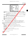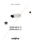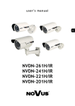
1
e- tp :// ww w. ht NVDN-801D N80 1D VD /N ov us er e/ N gh av e pr su e- am er /c ro e. er m ca u s e r ’s m a n u a l NVDN-801D 1.0 version - User’s Manual N80 1D INFORMACJE INFORMATION EMC (2004/108/EC) and LVD (2006/95/EC ) Directives CE Marking /N ov us Electromagnetic compatibility EMC 2004/108/EC. Low voltage LVD 2006/95/EC with further amendment. The Directive applies to electrical equipment designed for use with a voltage rating of between 50VAC and as well as 75VDC and 1500VDC. er e/ N VD Our products are manufactured to comply with the requirements of the following directives and national regulations implementing the directives: WEEE Directive 2002/96/EC gh Information on Disposal for Users of Waste Electrical and Electronic Equipment /c am er e- su pr av e This appliance is marked according to the European 1000VAC Directive on Waste Electrical and Electronic Equipment (2002/96/EC) and further amendments. By ensuring this product is disposed of correctly, you will help to prevent potential negative consequences for the environment and human health, which could otherwise be caused by inappropriate waste handling of this product. The symbol on the product, or the documents accompanying the product, indicates that this appliance may not be treated as household waste. It shall be handed over to the applicable collection point for used up electrical and electronic equipment for recycling purpose. For more information about recycling of this product, please contact your local authorities, your household waste disposal service or the shop where you purchased the product. ro RoHS Directive 2002/95/EC tp :// ww w. Information e- ca m er e. Out of concern for human health protection and friendly environment, we assure that our products falling under RoHS Directive regulations, regarding the restriction of the use of hazardous substances in electrical and electronic equipment, have been designed and manufactured in compliance with the above mentioned regulations. Simultaneously, we claim that our products have been tested and do not contain hazardous substances whose exceeding limits could have negative impact on human health or natural environment. The device, as a part of professional CCTV system used for surveillance and control, is not designed for self installation in households by individuals without technical knowledge. ht The manufacturer is not responsible for defects and damages that result from improper or inconsistent with user’s manual installation of the device in the system. All rights reserved © AAT Holding sp. z o.o. 2 NVDN-801D 1.0 version - User’s Manual N80 1D SAFETY INFORMACJE REQUIREMENTS WARNING! /N VD THE KNOWLEDGE OF THIS MANUAL IS AN INDESPENSIBLE CONDITION OF A PROPER DEVICE OPERATION. YOU ARE KINDLY REQUSTED TO FAMILIRIZE YOURSELF WITH THE MANUAL PRIOR TO INSTALLATION AND FURTHER DEVICE OPERATION. ov us WARNING! er e/ N USER IS NOT ALLOWED TO DISASSEMBLE THE CASING AS THERE ARE NO USER-SERVICEABLE PARTS INSIDE THIS UNIT. ONLY AUTHORIZED SERVICE PERSONNEL MAY OPEN THE UNIT INSTALLATION AND SERVICING SHOULD ONLY BE DONE BY QUALIFIED SERVICE PERSONNEL AND SHOULD CONFORM TO ALL LOCAL REGULATIONS gh WARNING! e- su pr av e PRIOR TO UNDERTAKING ANY ACTION THAT IS NOT DESCRIBED FOR THE GIVEN PRODUCT IN USER’S MANUAL AND OTHER DOCUMENTS DELIVERED WITH THE PRODUCT, OR IF IT DOES NOT ARISE FROM THE USUAL APPLICATION OF THE PRODUCT, MANUFACTURER MUST BE CONTACTED UNDER THE RIGOR OF EXCLUDING THE MANUFACTURER’S RESPONSIBILITY FOR THE RESULTS OF SUCH AN ACTION. am er IMPORTANT SAFEGUARDS AND WARNINGS ht tp :// ww w. e- ca m er e. ro /c 1. Prior to undertaking any action please consult the following manual and read all the safety and operating instructions before starting the device. 2. Please keep this manual for the lifespan of the device in case referring to the contents of this manual is necessary; 3. All the safety precautions referred to in this manual should be strictly followed, as they have a direct influence on user’s safety and durability and reliability of the device; 4. All actions conducted by the servicemen and users must be accomplished in accordance with the user’s manual; 5. The device should be disconnected from power sources during maintenance procedures; 6. Usage of additional devices and components neither provided nor recommended by the producer is forbidden; 7. Mounting the device in places where proper ventilation cannot be provided (e. g. closed lockers etc.) is not recommended since it may lead to heat build-up and damaging the device itself as a consequence; 8. Mounting the camera on unstable surface or using not recommended mounts is forbidden. Improperly mounted camera may cause a fatal accident or may be seriously damaged itself. The camera must be mounted by qualified personnel with proper authorization, in accordance with this user’s manual; All rights reserved © AAT Holding sp. z o.o. 3 NVDN-801D 1.0 version - User’s Manual N80 1D WARUNKI BEZPIECZEŃSTWA SAFETY REQUIREMENTS pr av e gh er e/ N ov us /N VD 9. Device should be supplied only from a power sources whose parameters are in accordance with those specified by the producer in the camera technical datasheet. Therefore, it is forbidden to supply the camera from a power sources with unknown parameters, unstable or not meeting producer’s requirements; 10. Signal cables (conducting TV or / and telemetric signal) should be placed in a way excluding the possibility of damaging them by accident. Special attention must be paid to cables getting from the camera and connecting the power supply; 11. To avoid equipment damage, whole TV circuit should be equipped with properly made discharge-, overload- and lightning protection devices. Usage of separating transformers is advised; 12. Electric installation supplying the device should be designed to meet the specifications given by the producer in such a way that overloading is impossible; 13. User cannot repair or upgrade the equipment himself. All maintenance actions and repairs should be conducted only by qualified service personnel; 14. Unplug the camera from the power source immediately and contact the proper maintenance department when the following occurs: Damages to the power cord or to the plug itself; su Liquids getting inside the device or exposure to strong mechanical shock; am er e- Device behaves in a way not described in the manual and all adjustments approved by the manufacturer and possible to apply by user himself, seem not to have any effect; Camera is damaged; tp :// ww w. e- ca m er e. ro /c Atypical behaviour of the camera components may be seen (heard). 16. In necessity of repairs attention to using only original replacement parts (with their parameters in accordance with those specified by the producer) should be paid. Non-licensed service and non-genuine replacement parts may cause fire or electrocution; 17. After maintenance activities tests should be run to ensure proper operation of all the functional components of the device. ht Attention! Technical changes reserved without prior notice and printing errors possible. All rights reserved © AAT Holding sp. z o.o. 4 NVDN-801D 1.0 version - User’s Manual N80 1D FOREWORD INFORMATION Screws 2 pcs. Cable for connecting additional video output User’s manual er e/ N Video camera ov us /N VD 1. PACKAGE CONTENTS Opener pr av e gh If any of the listed equipment has been damaged during transport or if the package is incomplete, the contents of package should be packed back to the original box. Contact the local NOVUS distributor for further assistance. e- ca m er e. ro /c am er e- Mechanical IR cut filter IR operation capability Horizontal resolution: up to 700 TVL Min. illumination: from 0.00002 lx/F=1.2 (DSS) Digital Slow Shutter (DSS) Auto iris DC lens: f=2.5 ~ 12 mm 3-axis camera module adjustment Digital zoom: 16x Wide Dynamic Range (SSDR) High Light Compensation (HLC) Digital Image Stabilizer (DIS) Digital Noise Reduction (DNR) Privacy zones: 12 Other functions: various picture effects, motion detection Full configuration directly from the camera (user friendly multi-lingual OSD) Enclosure color: - White: NVDN-801D-white - Black: NVDN-801D-black Power supply: 12 VDC tp :// ww w. su 2. MAIN CHARACTERISTICS ht All rights reserved © AAT Holding sp. z o.o. 5 NVDN-801D 1.0 version - User’s Manual N80 1D FEATURES AND SPECIFICATION 2. SPECIFICATION NVDN-801D Pick-up Element 1/3” SONY EXview HAD II CCD imager Horizontal Resolution 650 TVL – color mode, 700 TVL – B/W mode S/N Ratio 52 dB (AGC off) Auto (AES): 1/50 s ~ 1/120 000 s er e/ N Electronic Shutter ov us /N 0.1 lx/F=1.2 - color mode (1/50 s), 0.01 lx/F=1.2 - B/W mode (1/50s), 0.0002 lx/F=1.2 - color mode DSS, 0.00002 lx/F=1.2 - B/W mode DSS Min. Illumination Digital Slow Shutter (DSS) 1/25 s ~ 10.24 s Auto Gain Control (AGC) On/Off (2 levels) 5 modes: Manual/AWC/Outdoor/Indoor/ATW gh White Balance On/Off av e Wide Dynamic Range (SSDR) Backlight Compensation (BLC) On/Off (3 modes) pr High light Compensation (HLC) su Synchronization e- Day/Night Switching On/Off Internal Auto/Manual 3 s/5 s/7 s/10 s/15 s/20 s/30 s/40 s/60 s am er Filter Delay Flickerless Function Privacy Zones On/Off 12 Auto-iris DC: f=2.5 ~ 12 mm /c Lens Type 28° ~ 102° ro Angle of View (H) 1.0 Vp-p, 75 Ohm (BNC) e. Video Output er Digital Zoom tp :// ww w. e- ca m Set-Up Other Functions VD Model 16 x Multi-lingual On Screen Display (OSD) Digital Image Stabilizer (DIS), Digital Noise Reduction (DNR), Motion detection, Various picture effects: Mirror (horizontal) and 180˚ image rotation, Image sharpness adjustment Power Supply 12 VDC ± 10% Power Consumption 2.2 W Operating Temperature -10°C ~ 50°C Dimensions (mm) 130 (Ø) x 105.7 (H) 430 g ht Weight All rights reserved © AAT Holding sp. z o.o. 6 NVDN-801D 1.0 version - User’s Manual N80 1D FEATURES AND SPECIFICATION VD 3.1 Dimensions /N Base ov us Cover gh er e/ N Bubble am er e- su pr av e 3.2. View of the camera, layout of the camera items /c 1 ro 1 er e. 4 ca m 3 - joystick implementing UP, LEFT, RIGHT, DOWN, SET commands - extra video output (extra-VBS) - focus adjustment screw - zoom adjustment screw ht 1 2 3 4 tp :// ww w. e- 5 All rights reserved © AAT Holding sp. z o.o. 7 2 NVDN-801D 1.0 version - User’s Manual N80 1D INSTALLATION er e/ N ov us /N VD The camera module is mounted on the bracket that enables the possibility of 3-axis camera module adjustment. gh 4. INSTALLATION av e Prior to installation please familiarize yourself with the product, its parameters and installation process. e- am er /c ro e. ht tp :// ww w. e- ca er Rotate the camera cover and set a grove in the cover on a level with a gap in the base. Insert the opener, from the package, to a slot in the base of the camera and gently twist it. Remove the camera cover. Place base of the camera in a desired place and use its mounting holes as a drilling pattern. Drill holes for screws and cables. Screw the camera onto desired surface using included screws or different mounting kit (not included) if necessity arises. Adjust the position of the camera module. If required, loosen the screw blocking camera module. Adjust focal length and focus, using dedicated knobs. If needed, adjust the desired settings in the camera menu, using function buttons. Put the camera cover onto the base and press it, till distinctive unlocking “click” can be heard. Please ensure that masking shield does not block the field of view of the camera. m su pr To install the camera please follow the instructions below: All rights reserved © AAT Holding sp. z o.o. 8 NVDN-801D 1.0 version - User’s Manual N80 1D INSTALLATION VD 4.1 Connections video video er e/ N ground (GND) ov us /N The camera is equipped with a video and power cable finished with 2 plugs, one for video output (yellow one), the other for power supply 12VDC±10% (red one). Images below show plug polarization. + power av e gh - (GND) connect power supply to the power plug su connect video cable to the BNC plug e- pr The following connecting order should be kept: /c am er ATTENTION: Prior to connecting the power supply make sure that all required parameters (output voltage, output current and polarization) are correct. Using improper power suppl y may cause malfunction or camera damage. In such a case, warranty is void. ro 4.1.1 Extra video output connection ht tp :// ww w. e- ca m er e. Camera has an additional video output which is very useful during installation or camera maintenance. To use the Extra Video output please connect the included cable (mentioned in the chapter 1 equipment list) to the Extra Video connector presented in the chapter 3.2. All rights reserved © AAT Holding sp. z o.o. 9 NVDN-801D 1.0 version - User’s Manual N80 1D SETTINGS 5. SETTINGS VD NVDN-801D camera is equipped with an OSD menu. During camera operation, status information can be displayed on the screen. gh er e/ N ov us /N As mentioned before, a joystick is placed near the camera module for navigating and changing menu settings: er e. ro /c am er e- su pr av e In order to enter the menu press the joystick, which results in executing SET command. For choosing the submenus please move the joystick into UP, DOWN positions. If a symbol is present, enter particular sub-menu by pressing the SET button. To change the parameters use the LEFT and RIGHT joystick positions. In order to leave the menu select EXIT and press SET. Depending on the value of the parameter located to the right of the EXIT text, different actions are taken on exit: selecting SAVE and pressing SET means that the changes that have been made are saved and are kept even when the camera restarts. selecting NOT SAVE and pressing SET means that the changes that have been made are temporary and will be cancelled once the camera restarts. selecting RESET and pressing SET results in restoring factory defaults. To exit submenu please select RETURN position, and when Press SET to Return message is displayed at the bottom part of the screen press SET button to leave the menu . After one minute of inactivity in the menu camera will automatically exit from the programming mode. ht tp :// ww w. e- ca m 5.1 Main menu In order to enter the menu press the SET . The following main menu is displayed on the screen: MAIN SETUP 1.LENS 2.EXPOSURE 3.WHITE BAL 4.SSDR 5.BACKLIGHT 6.DNR3 7.DAY/NIGHT 8.SPECIAL 9.EXIT DC ATW OFF HLC ON COLOR SAVE All rights reserved © AAT Holding sp. z o.o. 10 NVDN-801D 1.0 version - User’s Manual N80 1D SETTINGS 5.1.1 LENS submenu This submenu allows for setting the lens parameters. Lens operating mode. VD LENS ov us Automatic lens mode. For that setting a submenus that allow for adjusting the BRIGHTNESS level in the range from 1 to 70, the iris speed IRIS SPEED and the precise setting of image sharpness FOCUS ADJ are available. 5.1.2 EXPOSURE submenu er e/ N DC /N MANUAL Manual settings of the lens operating mode. For that setting a submenu that allows for adjusting the BRIGHTNESS level in the range from 1 to 70 is available. This submenu allows for choosing and changing the settings of the parameters connected with AE and controlling the iris. gh EXPOSURE SETUP am er e- su pr av e 1.BRIGHTNESS ιιιιιxιιιιιιιιιιιι 25 2.SHUTTER MANUAL 3.AGC HIGH 4.SENS-UP --5.RETURN ro Automatically sets the shutter speed according to present light conditions. This option is available when DC or VIDEO option is selected in the LENS submenu. er --- Selection of shutter mode. e. SHUTTER /c BRIGHTNESS Selection of brightness level in the range from 1 to 70. e- This option will control the shutter speed automatically depending of the light conditions. For that setting a submenu that allows for setting MIN and MAX speed of the shutter is available. tp :// ww w. ESC ca m A.FLK (FLICKERLESS) The mode of flicker reduction in variable light conditions is equal to the shutter speed of 1/120s. This mode is available for any setting selected in the LENS position. ht MANUAL Manual setting of the shutter speed. For that setting a submenu that allows for setting the shutter speed (SHUTTER) in the range from 1/120000s to 512x(1/50s) is available. All rights reserved © AAT Holding sp. z o.o. 11 NVDN-801D 1.0 version - User’s Manual N80 1D SETTINGS Automatic Gain Control function. When OFF is selected, the function is switched off. When NORMAL is selected, the function is working with camera sensitivity smaller than the light intensity changes. When HIGH is selected, the function is providing bigger camera sensitivity than the light intensity changes. Please remember that increasing gain results in increasing brightness and noise level as well. SENS - UP Low shutter mode function. OFF - the function is switched off, AUTO - in low light conditions function automatically sets low shutter speed. After pressing SET button in this mode it is possible to set the multiplier of the basic shutter speed (1/50s in AUTO mode) in the range from x2 to x512. er e/ N ov us /N VD AGC This function is switched off when AGC is off or shutter mode is A.FLK or MANUAL. av e gh Please remember that together with selecting higher values from the low shutter range the image becomes brighter but simultaneously the noise level goes up and moving objects become blurred. pr 5.1.3 WHITE BAL submenu This mode (Auto Tracking White Balance) can be used in the 1700°K ~ 11000° color temperature range. am er ATW White balance mode e- WHITE BAL su This feature allows for setting appropriate color settings in various color temperature conditions. ro /c MANUAL Manual mode settings. In case of inappropriate color settings for ATW, AWC modes it is possible to set RED and BLUE color values manually . The range of changes is from 0 to 900 and is displayed as a line. The changes are seen immediately. The lines of changes are active only in WB manual mode. ca m er e. AWC→SET This mode (Auto White balance Control) allows for adaptive setting of white balance. In order to obtain the optimum state under the current illumination, direct the camera at a sheet of white paper and press SET button. When lighting parameters change ( e.g. light bulbs changed to halogen lamps, daylight to artificial light etc. ), procedure mentioned above should be repeated. This mode (Auto Tracking White Balance) can be used in the 4500°K~8500°K color temperature range (e.g. when using the camera inside the house). tp :// ww w. INDOOR e- OUTDOOR This mode (Auto Tracking White Balance) can be used in the 1700°K ~ 11000°K color temperature range (e.g. when using sodium vapour lamps). 5.1.4 SSDR submenu (Wide dynamic range) ht This function allows to effectively observe the scene with different illumination level. Function can be enabled (ON) or disabled (OFF). When ON is selected, a submenu that allows for setting the function intensity level in the range from 1 to 15 becomes available. All rights reserved © AAT Holding sp. z o.o. 12 NVDN-801D 1.0 version - User’s Manual N80 1D SETTINGS 5.1.5 BACKLIGHT submenu Backlight compensation mode. /N BACKLIGHT VD These compensation functions allow for enhancing visibility of the objects located in the foreground, surrounded by strongly illuminated background (BLC) or for enhancing visibility of the objects located near the strong light source (HLC). Function OFF. BLC BLC function allows for enhancing visibility of the objects located in the foreground, surrounded by strongly illuminated background. After pressing SET button in this mode submenu depicted below appears: BLC SETUP er e/ N ov us OFF LOW 38 109 54 121 LEVEL TOP BOTTOM LEFT RIGHT pr av e gh ιιιιιxιιιιιιιιιιιι ιιιιιιιιιιιιιxιιιι ιιιιιxιιιιιιιιιιιι ιιιιιιιιιιιιιιxιιι am er e- su Press SET to Return Submenu presented above allows for setting the size and location of the area where the BLC function will be active, furthermore it allows for setting the sensitivity of the function. Select the intensity of the function from available: LOW, MIDDLE, HIGH TOP Move upper part of the area up or down. ro /c LEVEL er e. BOTTOM Move bottom part of the area up or down LEFT e- High light compensation function. It allows for enhancing visibility of the objects located near the strong, point light source. If a strong, point light source appears on the screen, function will mask it allowing for effective observation of the scene itself (this function is best used to, for example, observe licence-plates of the cars). ht tp :// ww w. HLC Move right part of the area left or fight side. ca RIGHT m Move left part of the area left or right side. All rights reserved © AAT Holding sp. z o.o. 13 NVDN-801D 1.0 version - User’s Manual N80 1D SETTINGS Press the SET please, to display below submenu. /N ov us gh Press SET to Return er e/ N LEVEL MIDDLE LIMIT ALL DAY MASK COLOR RED MASK TONE ιιιιιιιιιιιιιxιιιι 25 TOP ιιιιιxιιιιιιιιιιιι 5 BOTTOM ιιιιιιιιιιιιιιxιιι 120 LEFT ιxιιιιιιιιιιιιιιιι 5 RIGHT ιιιιιιιιιιιιιιxιιι 172 VD HLC SETUP av e Submenu allows to set the size and location of the area in which the HLC function analyzes the level of illumination and sets the other HLC function options described below. Adjust level of the HLC function from available: LOW, MIDDLE HIGH. LIMIT Sets the lighting threshold that, when exceeded, activates the function. su pr LEVEL e- ALL DAY Threshold is set to low variations in illumination level. am er NIGHT ONLY Threshold is set to high variations in illumination level. MASK COLOR Select the colour of the masking area from available: RED, BLUE, CYAN, MAGENTA, BLACK. /c MASK TONE Adjusts opacity of masking area. TOP ro Moves upper part of the area up or down. e. BOTTOM Moves bottom part of the area up or down Moves left part of the area left or right side. RIGHT Moves right part of the area left or right side. m er LEFT e- ca Note: HLC function works only in the low-light conditions. It is activated automatically when level of the light is low enough for the function to execute properly and when a strong point light source appears on the screen. ht tp :// ww w. Because the effectiveness of HLC function relies mostly on the amount of light area in the screen, optimize the installation angle for the best HLC performance. All rights reserved © AAT Holding sp. z o.o. 14 NVDN-801D 1.0 version - User’s Manual N80 1D SETTINGS 5.1.6 DNR3 (Digital Noise Reduction) submenu This submenu allows for changing digital noise reduction settings. DNR Digital Noise Reduction function ON. OFF Digital Noise Reduction function OFF. /N ON VD Digital Noise Reduction function. ov us After selecting ON press the SET please, to display submenu allowing for adjustment of the digital noise reduction level, as depicted below. LEVEL RETURN 12 pr av e gh ιιιιιιιιιιιιιxιιιι er e/ N SDNR am er e- su Note: While working in DNR mode, image quality might slightly worsen. Digital noise reduction function is disabled when the AGC function is off. 5.1.7 DAY / NIGHT submenu DAY / NIGHT /c Camera switches between night (b/w) and day (color) mode automatically, depending on current illumination conditions. ro AUTO Selects operating mode of the IR cut filter. tp :// ww w. e- ca m er e. After pressing SET button the submenu depicted below appears. AUTO SETUP 1. BURST MODE 2. COLOR→B/W DURATION DWELL TIME 3. B/W →COLOR DURATION DWELL TIME 4. RETURN OFF FAST 5 SEK FAST 5 SEK ht BURST MODE Enable (ON) or disable (OFF) the BURST (color burst) signal. All rights reserved © AAT Holding sp. z o.o. 15 NVDN-801D 1.0 version - User’s Manual N80 1D SETTINGS gh er e/ N ov us /N VD COLOR→B/W Allows for configuring the switching from b/w to color mode. DURATION Selects color to b/w switching speed from available: FAST, SLOW DWELL TIME Sets the delay between color and b/w mode switching. Values range from 3 to 60 sec. B/W→COLOR Allows for configuring the switching from b/w to color mode. DURATION Selects b/w to color switching speed from available: FAST, SLOW DWELL TIME Sets the delay between b/w and color modes switching. Values range from 3 to 60 sec. EXTERN Not available. COLOR Camera works permanently in color mode. B/W Camera works permanently in B/W mod. For that setting a submenu that allows for enabling or disabling the BURST MODE is available. av e 5.1.8 SPECIAL submenu pr This submenu allows for setting the additional functions available in the camera. Allows for enabling the additional picture effects. ro IMAGE ADJ. OFF INT OFF OFF OFF USER /c am er e- su SPECIAL 1. IMAGE ADJ 2. CAM TITLE 3. SYNC 4. MOTON 5. PRIVACY 6. DIS 7. PROFILE 8. COMM ADJ 9. RETURN er e. MONITOR Allows for configuring camera picture parameters, depending on the type of monitor used. Allows for configuring the camera to enhance its LCD monitor cooperation capabilities, pressing SET displays additional submenu which allows for adjustment the LCD monitor display settings. USER Allows for configuring the camera to enhance its monitor (of non-standard types) cooperation capabilities, pressing SET displays additional submenu which allows for adjustment the display settings. tp :// ww w. e- ca m LCD Allows for configuring the camera to enhance its CRT monitor cooperation capabilities, pressing SET displays additional submenu which allows for adjustment the CRT monitor display settings. ht CRT All rights reserved © AAT Holding sp. z o.o. 16 NVDN-801D 1.0 version - User’s Manual N80 1D SETTINGS REVERSE flips the picture: OFF - Function off. /N VD V - REV Flips the picture vertically, H - REV Flips the picture horizontally (Mirror) HV - REV Rotate 180 degree the picture; ov us PIP - (Picture in Picture) Function displays a full-size image in the thumbnail. Used in digital zoom mode. The position of the thumbnail is adjustable. er e/ N D - ZOOM Digital zoom function. After selecting ON, pressing the SET displays additional submenu which allows for adjusting the digital zoom level, ranging from x0.1 to x16, OFF function off. FONT COLOR Selects the OSD font color av e gh SHARPNESS Screen sharpness function. After selecting ON, pressing SET displays additional submenu which allows for sharpness level adjustment, ranging from 1 to 20. OFF - function off. If the SHARPNESS level is too high the picture may become distorted or noisy. pr LANGUAGE Selects OSD language from available: ENGLISH, GERMAN, ITALIAN, FRENCH, SPANISH, RUSSIAN, CZECH, ROMANIAN, SERBIAN, SWEDISH, DANISH, TURKISH, PORTUGUESE, THAI. am er e- su CAM TITLE After selecting ON and pressing SET, a sub-menu appears, allowing for entering a string of characters that later is displayed on the screen, e.g. as camera title. Title may consist of up to 15 characters. Please select desired characters from the virtual keyboard, which becomes available after pressing SET. CAMERA TITLE SETUP CLR POS END m er e. ro /c ABCDEFGHIJKLM NOPRSTUVWXYZ abcdefghijklm noprstuvwxyz _ . 0123456789 ca CAMERA--------- tp :// ww w. e- Screen contains mainly alphanumerical characters, which may be used in camera’s title. Select desired character and please apply it by pressing SET key. Currently edited title is visible at the bottom of the screen. A line just above it contains buttons for editing the title. To enable particular functions, please highlight them as normal characters and confirm by pressing SET key. Button functions are described below: Moves character highlight cursor left. Moves character highlight cursor right ht POS Allows for adjusting the position of entered characters. CLR Erases the whole title. END Exits title editing menu. All rights reserved © AAT Holding sp. z o.o. 17 NVDN-801D 1.0 version - User’s Manual SYNC N80 1D SETTINGS Selects synchronization mode. INT Internal synchronization. This menu allows (provided, that ON option is selected) for turning a built-in motion detection feature on or off. Motion detection may simultaneously be conducted in eight independent zones (with their size and location selectable by user). Detection of motion with MOTION DET turned on results in Motion Detected message being displayed on the screen. ov us /N VD MOTION After selecting ON and pressing SET the submenu below is displayed, which allows for adjusting the motion detection function parameters. AREA1 OFF R_BOTTOM ιιιιιιιιιιιιιxιιιι 5 ιιιιιιιιιιιιιxιιιι 5 su pr av e gh 1. SENSITIVITY 2. AREA MODE 3. SEL POS 4. YPOS 5. XPOS 6. FILLSET 8. RETURN er e/ N MOTION DET am er e- SENSITIVITY Selects one of eight available motion detection zones (AREA1, AREA2, AREA3, AREA4). Each zone has different sensitivity level. The higher number, the higher sensitivity. AREA MODE Turns motion detection in selected zone on or off. SEL POS /c Selects edge of the area so its position can be changed. L_BOTTOM ro Left bottom area corner. e. R_BOTTOM Right bottom area corner. L_TOP er Left top area corner. R_TOP m Right top area corner. YPOS ca Change the selected area corner position toward vertical axis. XPOS e- Change the selected area corner position toward horizontal axis. After pressing SET button actually selected area will appear on the first plan. tp :// ww w. FILLSET Note: Disabling privacy zones prior to setting motion detection parameters is advised. PRIVACY Allows for enabling privacy zones (when turned ON). If this option is turned on, desired part of the screen is masked using four rectangular zones. ht Pressing SET displays submenu which allows for adjusting privacy settings. All rights reserved © AAT Holding sp. z o.o. 18 NVDN-801D 1.0 version - User’s Manual N80 1D SETTINGS /N ov us AREA1 ON GRAY ιιιιxιιιιιιιιιιιιιι 4 ιιιιιιιxιιιιιιιιιιι 39 ιιιιιιιxιιιιιιιιιιι 79 ιxιιιιιιιιιιιιιιιιι 13 ιιιιιιιxιιιιιιιιιιι 52 er e/ N 1. AREA 2. MODE 3. MASK COLOR 4. MASK TONE 5. TOP 6. BOTTOM 7. LEFT 7. RIGHT 8. RETURN VD PRIVACY AREA SETUP AREA SEL Selects one of twelve available privacy zones: AREA1, AREA2… AREA12. Turns selected privacy zone displaying on or off. After selecting ON and pressing SET displays submenu allowing for selected privacy zone location and size adjustment. gh MODE av e MASK COLOR Allows for setting the color of all privacy zones. Available colours: GREEN, RED, BLUE, BLACK, WHITE, GRAY. MASK TONE pr TOP Allows for adjusting brightness of masking zones in the range from 1 to 10. su Moves upper part of the area up or down. e- BOTTOM Moves bottom part of the area up or down Moves left part of the area left or right side. RIGHT Moves right part of the area left or right side. DIS am er LEFT /c Digital image stabilization function. It eliminates any picture movement which may occur due to external factors, such as wind. ON - function on, OFF function off. ro Note: Turning on the DIS function narrows the camera’s field of view. When using DIS function a decrease in resolution is possible, due to fact that the function uses digital zoom er e. PROFILE Predefined mode according to the picture condition m BASIC - Profile optimized to the most common environment condition. ca DAY/NIGHT - Profile optimized to the day or night conditions, respectively. e- BACKLIGHT - Profile optimized to distinguish the object from the background in a backlighting scene. tp :// ww w. ITS - Profile optimized to the traffic conditions. INDOOR - Profile optimized to a regular indoor lighting condition. USER - Profile for custom user settings. Not available. ht COMM ADJ All rights reserved © AAT Holding sp. z o.o. 19