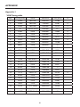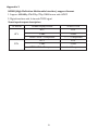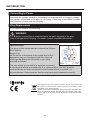
1
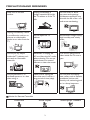
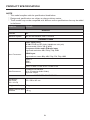
LCD TV RECEIVER User Manual Please read this manual carefully before using your television and keep this manual in a good place for future reference. MODEL: AT1916D TABLE OF CONTENT FOR YOUR SAFETY......................................................................................... 2 PRECAUTIONS AND REMINDERS............................................................ 3 IMPORTANT SAFETY INSTRUCTIONS.................................................... 4 PACKAGE CONTENTS.................................................................................. 5 PREPARATION.................................................................................................. 6 ATTACHING THE BASE..........................................................................................................6 PREPARING YOUR LCD TV FOR WALL MOUNTING..................................................6 PERIPHERAL CONNECTION GUIDE....................................................... 8 OPERATING INSTRUCTIONS..................................................................... 9 USING THE FRONT PANEL CONTROLS..........................................................................9 USING THE REMOTE CONTROL..................................................................................... 10 VIEWING MODE ILLUSTRATIONS.................................................................................. 12 CONNECTING EQUIPMENT............................................................................................ 13 USING THE MENUS.............................................................................................................. 19 PICTURE MENU..................................................................................................................... 19 SOUND MENU...................................................................................................................... 20 TV MENU................................................................................................................................. 20 FEATURES MENU.................................................................................................................. 21 PARENTAL MENU................................................................................................................. 22 COMMON INTERFACE MODULE................................................................................... 23 OAD OPERATION................................................................................................................ 24 TIPS............................................................................................................................................ 25 PRODUCT SPECIFICATION.......................................................................26 BEFORE CALLING SERVICE.......................................................................28 GLOSSARY.......................................................................................................29 APPENDIX.......................................................................................................30 INFORMATION..............................................................................................32 1 SYMBOL SA 1965 SA 1966 SYMBOL DEFINITION DANGEROUS VOLTAGE: The lightning flash with arrowhead symbol, within an equilateral triangle, is intended to alert the user to the presence of uninsulated “dangerous voltage” within the product’s enclosure that may be of sufficient magnitude to constitute a risk of electrical shock to persons. INSTRUCTIONS: The exclamation point within on equilateral triangle to alert the user to the presence of important operating and maintenance (servicing) instruction in the literature accompanying the appliance. Batteries installed warning Caution - Danger of explosion if battery is incorrectly replaced. Replace only with the same or equivalent type. The batteries (battery pack or batteries installed) shall not be exposed to excessive heat such as sunshine, fire or the like. FOR YOUR SAFETY Before operating the TV please read this manual thoroughly. This manual should be retained for future reference. NOTICE 1.Changes or modifications not expressly approved by the party responsible for compliance could void the user's authority to operate the equipment. 2.Shielded interface cables and AC power cord, if any, must be used in order to comply with emission limits. 3.The manufacturer is not responsible for any radio or TV interference caused by unauthorized modification to this equipment. It is the responsability of the user to correct such interference. WARNING: To prevent fire or shock hazard, do not expose the TV to rain or moisture. Dangerously high voltages are present inside the TV. Do not open the cabinet. Refer servicing to qualified personnel only. 2 PRECAUTIONS AND REMINDERS Place unit on an even surface. Unplug immediately if foreign materials fall inside the TV cabinet or if the TV falls. Do not cover or block any vents and openings. Inadequate ventilation may shorten the life of the unit and cause overheating. Do not open the TV cabinet. Avoid direct sunlight, dusty, high humidity and smoky areas. Do not put any object inside the TV cabinet, such as metals or flammable materials. Remember to unplug the AC cord from the AC outlet before cleaning. Do not use liquid cleaners or aerosol cleaners to clean the screen. Call service personnel to clean inside the TV once a year. Do not place the TV in confined spaces or in a box when using it. Make sure to unplug the unit when not in use for a long period of time (days). Do not place the display near water, such as bathtub, washbasin, kitchen sink, laundry tub, swimming pool or in a damp basement. Unplug immediately if there is a malfunction such as no picture, no video/audio, smoke or an odor from the TV. Notice for Remote Controller Avoid Falls 7 7 0 Avoid Sprays Cleaners 6 5 4 9 8 3 2 1 6 5 4 Avoid Liquids 3 2 1 3 2 1 9 8 6 5 4 0 7 9 8 0 3 IMPORTANT SAFETY INSTRUCTIONS Read before operating equipment 1. Read these instructions. 2. Keep these instructions. 3. Heed all warnings. 4. Follow all instructions. 5. Do not use this apparatus near water. 6. Clean only with a dry cloth. 7.Do not block any of the ventilation openings. Install in accordance with the manufacturers instructions. 8.Do not install near any heat sources such as radiators, heat registers, stoves, or other apparatus (including amplifiers) that produce heat. 9.Do not defeat the safety purpose of the polarized or grounded plug. A polarized plug has two blades with one wider than the other. A grounded plug has two blades and third grounding prong. The wide blade or third prong is provided for your safety. If the provided plug does not fit into your outlet, consult an electrician for replacement of the obsolete outlet. 10.Protect the power cord from being walked on or pinched particularly at plugs, extension cables , and the point where they exit from the apparatus. 11. Only use attachments/accessories specified by the manufacturer. 12.Use only with a cart, stand, tripod, bracket, or table specified by the manufacturer, or sold with the apparatus. When a cart is used, use caution when moving the cart/apparatus combination to avoid injury should the unit tip-over. 13.The TV should be operated only from the type of power source indicated on the label. If you are not sure of the type of power supplied to your home, consult your dealer or local power company. 14.Unplug this apparatus during lightning storms or when unused for long periods of time. 15.Refer all servicing to qualified service personnel. Servicing is required when the apparatus has been damaged in any way, such as power-supply cord or plug is damaged, liquid has been spilled or objects have fallen into apparatus, the apparatus has been exposed to rain or moisture, does not operate normally, or has been dropped. 16.The Class I apparatus shall be connected to a mains socket outlet with a protective earthing connection. 17.The mains plug or extension cable must be used to disconnect the device from mains power, and so should be easily accessible. 18.CAUTION – These servicing instructions are for use by qualified service personnel only. To reduce the risk of electric shock, do not perform any servicing other than that contained in the operating instructions unless you are qualified to do so. 19.For use only with Listed Wall Mount Bracket with minimum weight/load: Please see page.26 20.Tilt/Stability – All televisions must comply with recommended international global safety standards for tilt and stability properties of the cabinet design. ●● Do not compromise these design standards by applying excessive force to the front, or top, of the cabinet, which could ultimately overturn the product ●● Also, do not endanger yourself, or children, by placing electronic equipment/toys on the top of the cabinet. Such items could unexpectedly fall from the top of the set and cause product damage and/or personal injury. 4 21.Wall or Ceiling Mounting – The appliance should be mounted to a wall or ceiling only as recommended by the manufacturer. 22.Power Lines – An outdoor antenna should be located away from power lines. 23.Outdoor Antenna Grounding – If an outside antenna is connected to the receiver, be sure the antenna system is grounded to provide some protection against voltage surges and built up static charges. Section 810 of the National Electric Code, ANSI/NFPA No. 70-1984, provides information with respect to proper grounding of the mats and supporting structure grounding of the lead-in wire to an antenna-discharge unit, size of grounding connectors, location of antenna discharge unit, connection to grounding electrodes and requirements for the grounding electrode. See Figure below. ANTENNA GROUND CLAMP ANTENNA DISCHARGE UNIT ELECTRIC SERVICE EQUIPMENT GROUND CLAMPS GROUNDING CONDUCTORS POWER SERVICE GROUNDING ELECTRODE SYSTEM EXAMPLE OF ANTENNA GROUNDING AS PER NATIONAL ELECTRICAL CODE Note to the CATV system installer: This reminder is provided to call the CATV system installer’s attention to Article 820-40 of the NEC that provides guidelines for proper grounding and, in particular, specifies that the cable ground shall be connected to the 6 English grounding system of the building, as close to the point of cable entry as practical. Please, make sure to connect the power plug to the wall outlet socket after connecting the TV to the adapter! 24.Apparatus shall not be exposed to dripping or splashing and no objects filled with liquids, such as vases, shall be placed on the apparatus. 25. Excessive sound pressure from earphones and headphones can cause hearing loss. Adjustment of the equalizer to maximum increases the earphones and headphones output voltage and therefore the sound pressure level. PACKAGE CONTENTS ●● TV unit ●● Remote Control ●● Two (AA) Batteries for the Remote Control ●● Power Cord ●● User Manual ●● Quick Start Guide ●● CE Document 5 PREPARATION 2Secure the wall mount bracket to the back of your TV using four screws, as indicated in the illustration. IMPORTANT: Do not apply pressure to the screen display area which may compromise the integrity of the display. The manufacturer’s warranty does not cover user abuse or improper installations. M4 screws 100 mm 100 mm ATTACHING THE BASE IMPORTANT: The Base of the TV must be assembled prior to usage. M4 screws 1.Place TV unit face down on a soft and flat surface (blanket, foam, cloth, etc.) to prevent any damage to the TV. 2.Carefully align and insert the Base to the stand. NOTE Wall mount bracket & screws are not included. 3.Gently push the Base towards the TV until the locking mechanism locks into place. Please make sure to connect the power plug to the wall outlet socket after connecting the TV to the power cord! 1.Install the base stand; place the TV on a solid surface. Min 1m PREPARING YOUR LCD TV FOR WALL MOUNTING Ensure that the TV is placed in a position to allow free flow of air. Do not cover the ventilation openings on the back cover. To prevent unsafe situations, no naked flame sources, such as lighted candles, should be placed on or in the vicinity. Avoid heat, direct sunlight and exposure to rain or water. The equipment shall not be exposed to drips or splashes. We suggest that you keep your TV at least 2.36 inches (60 mm) from the wall to prevent cable interference. Before mounting your TV on the wall, you need to remove the base. For your safety, please use listed wall mount bracket with minimum weight of the TV without stand. (Please see page.26) To attach a wall mount bracket to your TV: 1Loosen the screws holding your TV to the stand and remove the stand base from the TV. 6 2.Connect the antenna cable or CATV cable to the aerial socket TV ANTENNA at the back of the TV set. 3. Remote control: Remove the cover of the battery compartment. Insert the 2 batteries supplied (Type AA 1.5V). 4. Power: Insert the power cord in the AC power wall socket. The power-state LED is on the front of the TV. If it is blue, the TV set is powered on. If it is red, the TV set is in standby. 5. Turn the TV on: Press the POWER key on the Remote control or the side panel control buttons. The TV will be turned on in a minute with display on the screen. Power Key 7 PERIPHERAL CONNECTION GUIDE AC POWER SERVICE PORT ླྀ ཻ ཹ ེ ཷ ྲྀ ཱ ི ཱི ུ ཱུ ① COMMON INTERFACE (CI) – Conditional Access Module (CAM) use only. Please contact your service provider for details. ②、③、④ AV IN – Connect the primary source for composite video devices, such as a VCR or video game. Use the white and red connectors to connect the external audio from the same source. ⑤ SERVICE PORT – Technician service use only. ⑥ Earphone Output – Connect to the headphones. When the headphone is inserted to the plug, all the speakers will be muted. ⑦TV ANTENNA – Connect to an antenna or digital cable (out-of-the-wall, not from Cable Box) for Digital TV. ⑧ SCART – Connect the video recorder or decoder to the television. Full SCART transmits RGB, CVBS video in/out, and audio in/ out; HALF SCART transmits S-Video, CVBS video in/ out, and audio in/ out. Note: SCART has monitor out. (CVBS/YPbPr/ATV/DTV) ⑨ PC IN – Connect the video and audio cables from a computer here. ⑩COMPONENT (Y/Pb/Pr with Audio L/R) – Connect the primary source for component video devices such as a DVD Player or set top box here. ⑪SPDIF (Digital Audio Out) – When a digital audio signal is associated with the input selected for viewing, the digital audio will be available on this SPDIF connection to your home theatre system. ⑫ HDMI – Connect the primary source for digital video such as a DVD multimedia player or set top box through this all digital connector. Once your equipment is connected, use the following procedure to view the input signal: Press the SOURCE button on the remote controller to select the relevant source to view. (ex: Press YPbPr button to select “YPbPr” if you have connected a video recorder to Component socket.) OPERATING INSTRUCTIONS 8 USING THE SIDE PANEL CONTROLS 1 2 3 4 5 6 7 1 VOL + VOL +: Press to increase the sound volume level. 2. VOL - VOL - : Press to decrease the sound volume level. 3. CH ▲ CH ▲: Press to select the next higher Programme number. 4. CH ▼ CH ▼: Press to select the next lower Programme number. 5. MENU Menu key: Press to open or exit the OSD (on-screen display) menu. 6. INPUT Input key: Press to select the input source. 7. i POWER Power key: Press to turn on / off (standby) the TV set. 9 USING THE REMOTE CONTROL Power Display Guide Source Wide MPX MENU Back up left right down POWER Press to turn ON/OFF (standby) the TV. 111 In digital TV/ analog TV, press DISPLAY key to show channel information banner and detail channel information banner in loop 222 In other input source, Press Display show the Input Source Press to display the Electronic Programme Guide. Press to toggle through input sources Scaling Mode ( Wide /auto/normal/zoom1 / zoom2) NICAM STEREO Broadcast : Stereo/Mono BILIGUAL Broadcast : Dual 1 / Dual 2 MONAURAL Broadcast: Mono FM-FM STEREO Broadcast: Stereo/Mono BILINGUAL Broadcast : Dual 1 / Dual 2 DVB-T Switching available audio track in a program Open/Exit Menu Return to the previous page of OSD meau,the exit of EPG or the exit of Channel list/input list/ OSD/the display information Press to adjust or confirm the various function items on the menu. Selection Confirm, in TV mode, if no active OSD OK is displayed, OK key is also defined as Channel List. Mute Mute on/off FAV Favorite Display the Favourite Channel List. CH+ Press or to browse through the TV channels. CHVol+ Vol- Press + or - to adjust the volume. 10 1 Number key 1 2 Number key 2 3 Number key 3 4 Number key 4 5 Number key 5 6 Number key 6 7 Number key 7 8 Number key 8 9 Number key 9 0 Number key 0 Teletext Press to display or close Teletext. •• In TV mode: It works only for turning on the subtitle and change to the next page marked as subtitle subtitle. •• In Text mode: Select the next page marked as a subtitle page and request it as the display page. Red color button to do teletext operation In R teletext mode, Green color button to do teletext operation In G teletext mode Yellow color button to do teletext operation In Y teletext mode Blue color button to do teletext operation In B teletext mode INDEX Index Press to return to page 100 or the index page. SIZE Size Press to change the font size: Full screen, Top half and Bottom half. Hold Press to stop changing pages. The text decoder stops receiving data. Reveal Reveal hidden information such as answers to a quiz. 11 VIEWING MODE ILLUSTRATIONS Normal Mode The original content would be at the centre of the screen. 16:9 Content 4:3 Content Wide Mode The original content in this mode has to fill the entire screen of the display. 16:9 Content 4:3 Content ZOOM Mode For those wide format images which are originally programmed into 4:3 frames with black bars around, this mode would stretch the image in both width and height for full display with active data. Same image in ZOOM mode 12 Using the Antenna or Cable for your VCR CONNECTING EQUIPMENT Coaxial (RF) Using Your Antenna or Digital Cable for DTV. 1. Turn off the TV and VCR. 2.Connect the “Output to TV”, “RF Out” or “Antenna Out” connector on the rear of your VCR to the TV ANTENNA connector at the rear of the TV. 1. Turn off the TV. 2.Connect the coaxial (RF) connector from your antenna or digital cable (out-of-thewall, not from the Cable Box) to the TV ANTENNA connector. 3. Turn on the TV and VCR. 4.Select ATV/DTV using the SOURCE button on the remote control or the control key on the side of the TV. 3. Turn on the TV. 4.Select ATV/DTV using the SOURCE button on the remote control or the control key on the side of the TV. NOTE If you have an off-air antenna or cable TV, connect it to the “Antenna In” connector on the rear of your VCR. Using Your Antenna or Cable for DTV. 1. Turn off the TV. 2.Connect the coaxial (RF) connector from your antenna or cable (out-of-the-wall, not from the Cable Box) to the TV ANTENNA connector at the rear of the TV 3. Turn on the TV. 4.Select ATV/DTV using the SOURCE button on the remote control or the control key on the side of the TV. 13 Connecting Your TV Set-Top Box For TV Set-Top Boxes with DVI Using HDMI 1.Turn off the TV and TV Set-Top Box. TV Set-Top Boxes that have a HDMI digital interface should be connected to the HDMI input of the LCD TV for optimal results. 2.Using a HDMI-DVI cable, connect the DVI end to your TV Set-Top Box and the HDMI end to the HDMI Input at the rear of the TV. Connecting your TV Set-Top Box 3.Turn on the TV and TV Set-Top Box. 4.Select HDMI using the SOURCE button on the remote, side of the TV, or directly by pressing the HDMI button on the Remote Control. NOTE The HDMI input on the TV supports Highbandwidth Digital Content Protection (HDCP). HDCP encrypts the transmission between the video source and the digital display for added security and protection. 1.Turn off the TV and TV Set-Top Box. 2.Connect a HDMI cable to the HDMI output of your TV Set-Top Box and the other end to the HDMI Input at the rear of the TV. 3.Turn on the TV and TV Set-Top Box. Refer to your TV Set-Top Box user manual for more information about the video output requirements of the product or consult your cable or satellite operator. 4.Select HDMI using the SOURCE button on the remote, side of the TV, or directly by pressing the HDMI button on the Remote Control. The DVI to HDMI connection provides video only. Connection to an alternate audio player is required for audio. NOTE The HDMI input on the TV supports Highbandwidth Digital Content Protection (HDCP). HDCP encrypts the transmission between the video source and the digital display for added security and protection. Refer to your TV Set-Top Box user manual for more information about the video output requirements of the product or consult your cable or satellite operator. 14 Using Component Video Connecting Your Basic Set-Top Box Connecting your TV Set-Top Box : Using Composite Video 1.Turn off the TV and TV Set-Top Box. 1.Turn off the TV and Set-Top Box. 2.Connect the Pr (red colour) connector on your TV Set-Top Box to the corresponding Pr (red colour) connector in the Component group. 2.Using an AV Cable, connect the Video (yellow colour) connector on your Set-Top Box to the corresponding Video (yellow colour) connector in the AV group at the side of the TV. 3.Connect the Pb (blue colour) connector on your TV Set-Top Box to the corresponding Pb (blue colour) connector in the Component group. 3.Using the red and white connectors, connect the cable to the audio output connectors associated with the Video output on your Set-Top Box and connect the other end to the audio connectors associated with the AV input at the side of the TV. 4.Connect the Y (green colour) connector on your TV Set-Top Box to the corresponding Y (green colour) connector in the Component group. 5.Using an audio cable (red and white connectors), connect the cable to the audio output connectors associated with the Component output on your TV SetTop Box and connect the other end to the audio connectors associated with the Component. 4.Turn on the TV and Set-Top Box. 5.Select AV using the SOURCE button on the remote, side of the TV or directly by pressing the VIDEO button on the Remote Control. 6.Turn on the TV and TV Set-Top Box. 7.Select YPbPr using the SOURCE button on the remote, side of the TV or directly by pressing the YPbPr button on the Remote Control. NOTE Refer to your TV Set-Top Box user manual for more information about the video output requirements of the product or consult your cable or satellite operator. 15 Using Coax (RF) Connecting your DVD Player 1.Turn off the TV and Set-Top Box. 1.Turn off the TV and DVD player. 2.Using a Coax (RF) cable, connect one end to the TV OUT (RF) on your Set Top Box and the other end to the TV input at the rear of the TV. 2.Connect a HDMI cable to the HDMI output of your DVD player and the other end to the HDMI Input at the rear of the TV. 3.Turn on the TV and Set-Top Box. 4.Select HDMI using the SOURCE button on the remote, side of the TV or directly by pressing the HDMI button on the Remote Control. 3.Turn on the TV and DVD player. 4.Select ATV/DTV using the SOURCE button on the remote control or the control key on the side of the TV. For DVD Players with DVI: 1. Turn off the TV and DVD player. 2.Using a HDMI-DVI cable, connect the DVI end to your DVD player and the HDMI end to the HDMI Input at the rear of the TV. 3.Turn on the TV and your DVD player. 4.Select HDMI using the SOURCE button on the remote, side of the TV, or directly by pressing the HDMI button on the Remote Control. NOTE Refer to your Set Top Box user manual for more information about selecting the video or RF output of the product. Connecting Your DVD Player Using HDMI DVD players that have a digital interface such as HDMI (High Definition Multimedia Interface) should be connected to the HDMI input of the LCD TV for optimal results. NOTE Refer to your DVD player user manual for more information about the video output requirements of the product. The DVI to HDMI connection provides video only. Connection to an alternate audio player is required for audio output. 16 Using Component Video Using SCART Connecting your DVD Player Connecting your DVD Player : 1.Turn off the TV and DVD player. 1.Turn off the TV and DVD player. 2.Connect the SCART socket of your DVD player to the SCART socket of the TV. 3.Turn on the TV and DVD player. 4.Select AV using the SOURCE button on the remote, side of the TV, or directly by pressing the VIDEO button on the Remote Control. 2.Connect the Pr (red colour) connector on your DVD player to the corresponding Pr (red colour) connector in the Component at the rear of the TV. 3.Connect the Pb (blue colour) connector on your DVD player to the corresponding Pb (blue colour) connector in the Component group at the rear of the TV. 4.Connect the Y (green colour) connector on your DVD player to the corresponding Y (green colour) connector in the Component group at the rear of the TV. 5.Using an audio cable (red and white connectors), connect the cable to the audio output connectors associated with the Component output on your DVD player and connect the other end to the audio connectors associated with the Component input at the rear of the TV. 6.Turn on the TV and DVD player. 7.Select YPbPr using the SOURCE button on the remote, side of the TV or directly by pressing the YPbPr button on the Remote Control. NOTE Refer to your DVD player user manual for more information about the video output requirements of the product. 17 Using Composite (AV) Video NOTE Refer to your VCR or Video Camera user manual for more information about the video output requirements of the product. Connecting your DVD Player Connecting to a PC 1.Turn off the TV and DVD player. 2.Connect the Video (yellow colour) connector on your DVD player to the Video (yellow colour) connector in the AV group. 3.Connect the R (red colour) and L (white colour) audio connectors on your DVD player to the corresponding R (red colour) and L (white colour) audio input connectors in the AV group. 4.Turn on the TV and DVD Player. 5.Select AV using the SOURCE button on the remote, side of the TV or directly by pressing the VIDEO button on the Remote Control. 1.Turn off the TV and PC. 2.Connect a 15-pin D-Sub RGB (VGA) cable to the RGB output of your PC and the other end to the VGA input at the rear of the TV. 3.Connect the Audio Out on your computer to the AUDIO input at the rear of the TV. 4. Turn on the TV and PC. 5.Select VGA using the SOURCE button on the remote, side of the TV or directly by pressing the PC button on the Remote. Using SCART Connecting Your VCR or Video Camera NOTE For the best picture quality when connecting a computer through VGA, set your computer timing mode to native resolution of panel. Please refer to the PC or graphic card’s user guide for additional information on how to set the timing mode and the video output requirements of the product. 1.Turn off the TV and VCR or Video Camera. 2.Connect the SCART socket of your VCR or Video Camera to the SCART socket of the TV. 3.Turn on the TV and VCR or Video Camera. 4.Select AV using the SOURCE button on the remote, side of the TV or directly by pressing the VIDEO button on the Remote Control. 18 USING THE MENUS 8. Advanced Control: [Noise Reduction] - To filter out and reduces the image noise and improve picture quality. Select the effect degrees from Off, Low, Medium, High, or Auto. 1.Press the MENU/BACK button to display or close the main menu 2.Use the Navigation Ring to move around to select, adjust or confirm an item in the OSD (On Screen Display) menu. [Flesh Tone] - To adjust the skin colour to be more natural. Press the MENU/BACK button to enter the main OSD. Adjust the items including Picture, Sound,TV, Features, and Parental. However, some function items in the menus may only be enabled in the particular source modes. [Back Light] - To make the background colour brighter or darker. [ACM] - Adaptive Contrast Management(ACM),auto adjusts the brightness of the screen to show more depths in the darker areas. PICTURE MENU The Picture menu in most source modes shows as below. It provides several video adjustment items for user fine tuning the video display. 1. Scenario Mode: To set the best picture appearance to a predefined picture setting from Standard, Movie, Sport,Concert, Game or User. 2. Brightness: To brighten the dark parts of the picture. 3. Contrast: To sharpen the picture quality. 4. Colour: To add or reduce colour. 5. Tint: To adjust the picture tint. 6. Sharpness: To improve detail. 7. Colour Temperature: To choose between Normal (neutral), Warm (redder), and Cool (bluer). 19 SOUND MENU TV MENU The Sound menu provides audio adjustment for user to modify the audio setting. 1. Country: To select the relevant country. This is the country you are in, or the country whose channels you want to receive if you live near its borders. 1. Sound Mode: To set the TV to a predefined sound setting from User, Music, or Speech. 2. Audio Carrier (ATV only): Select Stereo, Dual 1, Dual 2, or Mono for ATV channel. 2. Balance: To adjust the balance between left and right channels. 3. Sound Effect: Advanced sound mode with virtual audio effects. 3. 1st and 2nd Audio: Use this function when two or more audio languages are broadcast. This is the language to be used for digital channels if it is available. 4. Steady Sound: Choose On or Off to adjust volume to be consistent across programmes and channels automatically. 4. Channels: Enter the channels submenu, and choose from Channel Scan, Update Scan, Single RF Scan, Analog Manual Scan, Channel Skip, Channel Sort, Channel Edit, Decoder, and Analog CH Fine Tune. 5. Type: This function enables you to choose the type of the additional narration during the TV watching from Normal, Hard of Hearing, or Audio Description. Hard of Hearing: This function provides narration to deaf and hard of hearing viewers. [Channel scan] - Channel Scan will retune the television automatically. It is recommended to run the Channel Scan periodically to ensure that all new services are added. 6. Audio description: When the Type is set to “Audio Description”, you can adjust the volume of the audio description. [Update scan] - Search the new channels automatically that are not in the channel list. 20 [Single RF Scan (Digital Only)] Enter the Single RF Scan in the Channels submenu to scan digital channels. Note: The following RC number-mapping table will not be shown on the TV screen. RC Available characters 0 1 2 3 4 5 6 7 8 9 . @ _ A B D E G H J K M N P Q T U W X 0 C F I L O R V Y 1 a d g j m S t Z b e H k n p u w c f i l o q v x 2 3 4 5 6 r 8 y s 7 z 9 [Decoder (Analog only)] - Channel Decode support the Canal+ (paid television channel); however, the channel also broadcast some un-encrypted programs. These programs without encryption can be viewed free of charge. [Analog Manual Scan] - The television can be tuned-in manually using Analog Manual Scan. Use the number keys to enter the Start Frequency to scan up or scan down. [Analog CH Fine Tune] - Select Analog CH Fine Tune in the Channels submenu to adjust the frequency. [Channel skip] - To prevent certain programs from being viewed by pressing CH + / - buttons on the remote control, the program position can be skipped. Tip: The skipped program may not be found by pressing CH + / - buttons but can be access by pressing number buttons directly. Tip: The skipped program may not be found by pressing CH Λ / V but can be accessed by pressing number buttons directly. [Channel sort] - Change the order of the Channel List. [Channel Edit] - Enter the Channel Edit in the channels submenu to edit the channel number and channel name by using the number buttons 0~9. 21 FEATURES MENU will be displayed. The Features menu in TV mode shows as below. This menu gives users the most flexibilities to satisfy their generally demands. According to the various requirements in different source modes, certain features should be hidden (disable) on the menu. The details footnotes will be described clearly below. [1st Subtitle 2nd Subtitle] - To select your primary subtitle language and your secondary subtitle language. [Subtitle Type] - To choose the subtitle type from normal or hearing impaired. 5. Teletext Language: [Digital Teletext Language] - To select the teletext language. [Decode Page Language] - To set the teletext language to the regional location. 6. Common Interface: This menu appears with your CI supplier information. 7. HDMI Scan Info (HDMI only): [Automatic] - Set to underscan or overscan automatically when the video signal is detected. 1. Menu Language: To select the on-screen display menu language. [Underscan] - When the video signal is detected, all active pixels and lines are displayed with or without border. 2. Picture Format: To select the available display format from Auto, Normal, Native (HDMI only), Zoom 1, Zoom2, or Wide. [Overscan] - When the video signal is detected, some active pixels and lines at the edges are not displayed. 3. Time: [Time Zone] - To select the time zone you are in. 8. Reset Default: To reset all TV settings to the original factory values. [Time] - To set the time and date or select auto synchronization. PARENTAL MENU Tip: Before you want to set the time and date by your own, please make sure Auto synchronization is Off. Enable you to control special functions for the TV channels. [Sleep Timer] - To set the TV to turn itself off within a certain time. 4. Subtitle: [Analog Subtitle] - To display the transmitted subtitle on the screen. Either this text can be permanently displayed (assuming that the service is available in the broadcast) or only when mute is active. [Digital Subtitle] - Use the Digital Subtitle function when two or more subtitle languages are broadcasted. If subtitle data in a selected language is not broadcasted, the default language subtitle 1. Channel Block: To block certain TV channels. 2. Parental Guidance: To control access programs based on their age ratings. All 22 the Smart Card into the CI slot located at the side of the TV. settings apply to digital channels. Note: This function operates according to information from the broadcasting station. Therefore if the signal has no information, this function does not operate. 2. Turn on the TV and press MENU and select the TV submenu. “Common interface” will be displayed if the CA module is detected. Wait for few moments until the card is activated. 3. Input Block: To disable the specific external input signals. 4. Set Password: To set or change your password. Please follow the instructions to set it. All number combinations from 0000 to 9999 are valid. Tip: Remember that 5351 is the default Change Password code. If your access code has been changed or you have forgotten the code, you can always get in by inputting the default code. 5. Clear All: To clear all the settings in the parental submenu. 3. Select Common Interface to view the menu options and information on the inserted CI card. COMMON INTERFACE MODULE - The Common Interface CI Slot, is designed to accept the Conditional Access CA Module coupled with a Smart card, in order to view pay TV programmes and additional services. Contact your Common Interface service provider for further information about modules and subscription options. Please note that CA modules and smart cards are not included. 4. Press OK to access the card menu, for more details refer to the module’s instruction manual. Smart Card CA Module WARNING: Switch off your TV before any module is inserted into the Common Interface slot. 1. Correctly insert the CA Module and then 23 Operation 1. When you find the channel a message will be displayed. Over Air Download Software ID : XXXXXXXX A New Version of software is detected.Do you want to upgrade it? Accept Remind me Later Select Next 2. Use ▲ or ▼ to accept or postpone the update, then press the ► button to select to action. Over Air Download Software ID : XXXXXXXX Searching 0% 5. When module is removed, the “Common Interface” menu will disappear from the screen. Back Over Air Download Software ID : XXXXXXXX Downloading... This process may take up to 25 minutes 12% Back Over Air Download Software ID : XXXXXXXX Seraching. OAD OPERATION OAD for Software Update function: 1. If you receive a message about updating your TV, you will find the software update in the Download menu. The update is transfered over a special receiving channel. 2. You must search for a channel with the update information. Additional information is available from the TV shop or the Internet. Accept Reject Select 24 Next TIPS Over Air Download Software ID : XXXXXXXX Care of the screen Do not rub or strike the screen with anything hard as this may scratch or damage the screen permanently. Unplug the power cord before cleaning the screen. Dust the TV by wiping the screen and the cabinet with a soft, clean cloth. If the screen requires additional cleaning, use a clean, damp cloth. Do not use liquid cleaners or aerosol cleaners. Programming... 69% Warring : During the process. Please do not unplug the TV Set power code as this lead to defective TV Set. 3. After the update has finished, use ▲ or ▼ to select Accept and restart the TV. The software update will be completed when the TV restarts. Mobile telephone warning To avoid disturbances in picture and sound, malfunctioning of your TV or even damage to the TV, keep away your mobile telephone from the TV. Over Air Download Software ID : XXXXXXXX Software upgrades successfully! Restart the TV now? End of life directives We take care to produce environmentally friendly products. Your new TV contains materials that can be recycled and reused. At the end of its life, specialized companies can dismantle the TV to recover reusable materials an minimise waste. Please ensure you dispose of your previous TV according to local regulations. Accept Reject Select Next OK Exit NOTE:You must not switch off the TV during this process! 25 PRODUCT SPECIFICATION NOTE * This model complies with the specifications listed below. * Designs and specifications are subject to change without notice. * These models may not be compatible with features and/or specifications that may be added in the future. Model No. AT1916D DISPLAY Viewable 18.5” Television System PAL, SECAM standard, DVB-T standard CONNECTIONS Tuner input (75Ω) PC IN: D-SUB and PC Audio (Headphone mini-jack) Recommended: 1366 x 768 @ 60Hz Component Video and L/R Audio input Supported resolution: 480i, 576i/p, 720p, 1080i Rear Connectors HDMI input Supported scan rates: 480p, 480i, 576p, 576i, 720p, 1080i SCART 1 SPDIF HDMI 1 SCART 1: RGB + CVBS in/out + audio in/out Side Connectors COMMON INTERFACE AV In (Composite Audio/ Video) Earphone Output WEIGHT & DIMENSIOIN Dimensions with Stand (W x H x D) 455 x 338 x 145 mm Weight with Stand 3.7 kg Weight without Stand 3.45 kg and Base 26 WALL MOUNTING VESA-compatible wall bracket (W x H) 100 x 100 mm Screw type Metric 4x10 mm POWER Power Consumption 50 W Standby < 1W Mains Power AC 100-240 V~, 50 / 60Hz Audio Power 3W + 3W Ambient Temperature 5°C - 35°C PACKAGE CONTENTS Supplied Accessories TV unit x1 Power cord x1 Remote control x1 (with two size AA alkaline batteries) User manual x1 Quick Start Guide x1 CE Document x1 27 BEFORE CALLING SERVICE Please make these simple checks before calling service. These tips may save you time and money since charges for receiver installation and adjustments of customer controls are not covered under your warranty. Symptoms Items to Check and Actions to follow “Ghost ” or double image *This may be caused by obstruction to the antenna due to high rise buildings or hills. Using a highly directional antenna may improve the picture. No power *Check if the TV’s AC power cord is plugged into the mains socket. *Unplug the TV, wait for 60 seconds. Then reinsert plug into the mains socket and turn on the TV again. No picture *Check antenna connections at the rear of the TV to see if it is properly connected to the TV. *Possible broadcast station trouble. Try another channel. *Adjust the contrast and brightness settings. *Check the Closed Captions control. Some TEXT modes could block the screen, Good picture but no sound *Increase the VOLUME. *Check if the TV is muted; press the MUTE button on the remote control. Good sound but poor colour *Adjust the contrast, colour and brightness settings. Poor picture *Poor picture quality may occur when an activated S-VHS camera or camcorder is connected to your TV and the other peripheral at the same time. Switch off one of the peripherals. Snowy picture and noise *Check the antenna connection Horizontal dotted line *This may be caused by electrical interference (e.g. hairdryer, nearby neon lights, etc.) *Turn off the equipment. Television not responding to remote control *Check whether the batteries are working. Replace if necessary *Clean the remote control sensor lens on the TV. *You can still use the buttons at the front of your TV. *Select the TV mode to ensure your remote control is set in the TV mode. 28 GLOSSARY TV TV displays are technically defined as being capable of displaying a minimum of 720p or 1080i active scan lines. HDMI Inputs High-Definition Multimedia Interface Audio / Video Inputs Located on the rear of the receiver, these connectors (RCA phono type plug) are used for the input of audio and video signals. Designed for use with VCRs (or other accessories) in order to receive higher picture resolution and offer sound connection options. Menu An on-screen listing of features shown on the TV screen is made available for user adjustments. RF Radio Frequency or modulated signal design used as the carrier for television broadcasts. Sleep Timer You can set a time period after which the TV will turn off automatically. 29 APPENDIX Appendix 1 VGA Timing table Item H.Freq.(KHz) Mode Resolution V.Freq.(KHz) 1 31.469 IBM VGA 640x350 70.086 2 31.469 IBM VGA 720x400 70.087 3 31.469 IBM VGA 640x480 59.94 4 35 MACINTOSH 640x480 67 5 37.861 VESA 640x480 72.809 6 37.5 VESA 640x480 75 7 35.156 VESA 800x600 56.25 8 37.879 VESA 800x600 60.317 9 48.077 VESA 800x600 72.188 10 46.875 VESA 800x600 75 11 49.7 MACINTOSH 832x624 75 12 48.363 VESA 1024x768 60.004 13 56.476 VESA 1024x768 70.069 14 60.023 VESA 1024x768 75.029 15 61.08 IBM XGA-2 1024x768 75.781 16 44.772 VESA CVT 1280x720 59.855 17 47.776 VESA 1280x768 59.87 18 60.289 VESA 1280x768 75 49.702 VESA 1280x800 59.81 19 47.72 VESA CVT 1366x768 59.799 20 63.981 VESA 1280x1024 60.02 21 79.976 VESA 1280x1024 75.025 55.935 VESA 1440x900 59.887 70.635 VESA 1440x900 74.984 22 65.29 CVT1.76MW 1680x1050 59.954 23 64.674 CVT1.76MW-R 1680x1050 59.883 24 66.587 CVT2.3MA-R 1920x1080 60 30 19" Appendix 2 HDMI (High Definition Multimedia Interface) support format 1. Support 480i/480p, 576i/576p, 720p, 1080i format with HDCP. 2. Digital interface with 4 channels TMDS signal. Scart input/output description TV Source ATV DTV Screen Display Source SCART1 Out ATV ATV CVBS CVBS HDMI / VGA / Component -- / -- / Component DTV DTV CVBS CVBS HDMI / VGA / Component -- / -- / Component 31 INFORMATION Connecting to Power Check that the voltage marked on the product corresponds with your supply voltage. This product is fitted with a 16A plug (or 10 A plug). If this plug is unsuitable or needs to be replaced, please note the following : Plug Replacement If you need to replace the fitted plug. WARNING : Never connect live or neutral wires to the earth terminal of the plug. Only fit an approved 16A plug. If in doubt, consult a qualified electrician. IMPORTANT The wires in this mains lead are coloured as follows: Blue-Neutral Brown-Live As the colors of the wires in the mains lead of this apparatus may not correspond with the coloured markings identifying the terminals in your plug, proceed as follows: The wire which is coloured blue must be connected to the terminal which is marked with N or coloured blue. The wire which is coloured brown must be connected to the terminal which is marked L or coloured brown. Always ensure that the plug cord grip is fastened correctly. CE marking The shipped version of this device complies with the requirements of EEC directives 2004/108/EC "Electromagnetic compatibility" and 2006/95/EC "Low voltage directive" WASTE ELECTRICAL PRODUCTS SHOULD NOT BE DISPOSED OF WITH HOUSEHOLD WASTE. PLEASE RECYCLE WHERE FACILITIES EXIST. CHECK WITH YOUR LOCAL AUTHORITY FOR RECYCLING ADVICE. 32