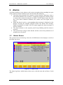
1
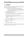
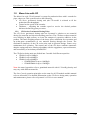
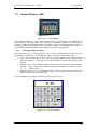
Line Control Mono Line with CD USER MANUAL P.O.B. 1122 Afula Illit 18550, Israel Tel: +972-4-6069700 Fax: +972-4-6405911 [email protected] www.sysmetric-ltd.com Manual Number: 1CD101 June, 2011 Line Control – Mono line with CD User Manual Table of Contents 1. INTRODUCTION....................................................................................... 3 1.1. LINE CONTROL............................................................................................... 3 1.2. MONO LINE WITH CD .................................................................................... 4 1.2.1. CD Series Gravimetric Dosing Units ..................................................... 4 1.3. CONTROL DISPLAY - HMI.............................................................................. 5 1.3.1. Entering Numeric Values ....................................................................... 5 1.3.2. Dosing Unit Screens* ............................................................................. 6 1.3.3. Line Control Screen ............................................................................... 6 1.4. LINE SERVICE SCREEN ................................................................................... 7 1.4.1. Line Speed Screen .................................................................................. 8 1.4.2. Line Speed Calibration Screen ............................................................... 9 2. SYSTEM OPERATION ........................................................................... 10 2.1. PRODUCTION STABILITY AND ACCURACY ................................................... 11 2.1.1. CD Weighing Bucket Loadcell ............................................................. 11 2.1.2. CD Mixer Inlet Proximity Switch ......................................................... 11 2.1.3. CD Mixer Rotation Proximity Switch................................................... 11 2.1.4. Raw Material Supply ............................................................................ 11 2.1.5. Batch Preparation Process Time ......................................................... 12 2.1.6. Batch Size ............................................................................................. 12 2.1.7. Screw Capacity Out of Range .............................................................. 12 3. ALARMS ................................................................................................... 13 3.1. ALARMS SCREEN ......................................................................................... 13 3.2. ALARMS LIST ............................................................................................... 14 3.2.1. “Total Layers Ratio is Not 100%” .......... Error! Bookmark not defined. 3.2.2. “Low Battery in Line PLC – Replace Soon” ....................................... 14 3.2.3. “Automatic Speed Calibration Out of Range” .................................... 14 3.2.4. “Automatic Speed Calibration – Unstable Speed” .............................. 14 3.2.5. “No Digital Speed Pulses” .................................................................. 15 3.2.6. “CLK Communication Error to CD#”.... Error! Bookmark not defined. 3.2.7. “Extruder # RPM Too High” ............................................................... 15 3.2.8. “Exception Output Ex#” ...................................................................... 15 www.sysmetric-ltd.com -2- Line Control – Mono line with CD User Manual 1. Introduction 1.1. Line Control Sysmetric‟s Line Control systems are designed to control the different sub-systems of the production line in order to manufacture the end product with the desired properties. The different sub-systems and controls are: Raw material handling – can be carried out by one of two systems: o Graviman – loss-in-weight follow-up on the extruder throughput. o CD Series – batch type gravimetric dosing units for preparing defined mixtures of raw material. The extruder‟s throughput is determined and monitored by the batch preparation rate. Material handling can also include conveying the raw material to the Graviman/CD and to the extruder. Extruder – controlling the extruder speed. IBC and calibrator cage in blown film lines– controlling the air exchange inside the bubble and the calibrator position to form the desired width of layflat. Nip-roll – tuning the nip-roll speed for the desired Meter/Minute. Tension and Winder – adjusting the tension rolls and winder speed to tense the lay-flat and wind it on the reels. Temperature – controlling the temperature of the extruder, the die and the tension rolls. Remote control – setting parameters to the production line and data acquisition from a remote PC (Minuman software). By controlling and monitoring those sub-systems, the Line Control can ensure production with specified properties of: Width Thickness (gram-per-meter) Layers Ratio (in multi-layer production lines) The different models of Sysmetric‟s Line Control systems involve different combinations of the above mentioned sub-systems of the production line and can control part or all the parameters of the blown film. www.sysmetric-ltd.com -3- Line Control – Mono line with CD User Manual 1.2. Mono Line with CD The Mono Line with CD is Sysmetric‟s system for production lines with 1 extruder for pipes, sheets etc. This system involves the following: CD Series gravimetric dosing unit (the CD model is selected to fit the production line throughput). Control on the speed of the extruder. Thickness – adjusting the extruder speed to receive the desired product thickness defined by gram-per-meter. 1.2.1. CD Series Gravimetric Dosing Units The CD Series gravimetric dosing units are Sysmetric‟s solution to raw material dosing for extrusion and injection molding processes. The CD doser reduces material cost, utilizing its high accuracy to lower the amount of expensive additives in the product. The batch weighing nature of the doser offers calibration-free operation and up-to-the-gram accumulation of raw material flowing through the system. The mechanical simplicity of the CD series units, and its practical design, ensures easy maintenance-free operation. The control unit of the CD doser combines automatic adaptive tuning and noise filtering algorithms with the ruggedness, open architecture, and extensibility of an industry-standard PLC. The CD Series dosing units are divided into 5 models for different capacities: CD100 for up to 100Kg/h CD400 for up to 400Kg/h CD800 for up to 800Kg/h o CD800HD200 for up to 1000Kg/h o CD800HD400 for up to 1200Kg/h Note: the stated capacities refer to granulated material with 0.5 Liter/Kg density and may vary with different materials. The Line Control operation principles are the same for all CD models and this manual refers to all models. For detailed information on the CD Series dosing units, operation and maintenance, please refer to Sysmetric‟s CD Series user manual. www.sysmetric-ltd.com -4- Line Control – Mono line with CD User Manual 1.3. Control Display - HMI Figure 1.3-1 – Control display The control display is a color touch-screen panel. All operations on the display are carried out by pressing gently on the display. Activating a button is carried out by pressing gently on the display where the button appears. Changing numeric values is carried out by pressing gently on the display where the value appears. 1.3.1. Entering Numeric Values Several screens (e.g. LINE screen) have one or more editable numeric items (e.g. the percentage of each layer). To modify the value of an item, follow these steps: 1. Select the item that you want to edit by pressing gently on the display where that item appears. A pop-up screen with numeric keypad will appear on the display. 2. Enter the new value using the numeric keypad. If the item has a decimal point, use the „.‟ key to move to the fractional part. For example, to enter 12.3, press „1‟, „2‟, „.‟ followed by „3‟. 3. Press the Enter key to confirm the change. The keypad screen will close and the item will receive the new value. Cancel editing by pressing the X button in the keypad screen. Figure 1.3-2 – Numeric keypad www.sysmetric-ltd.com -5- Line Control – Mono line with CD User Manual 1.3.2. Dosing Unit Screens* *For detailed explanation see CD dosing unit user manual. 1.3.3. Line Control Screen The line Control screen shows the production parameters and line speed. To access the Line Control screen go to MAIN > CONTROL Figure 1.3-3 – Line screen The Line Control screen shows the following data: Product Mass [gr/m] – The SET and ACTUAL gram-per-meter Line Speed [m/min] – The ACTUAL line speed Ex‟ Capacity [kg/h] – The SET (is Actual Set usually from potentiometer) and ACTUAL extruder capacity Auto/Manual switch – Auto or Manual line control mode selector Status window – Shows line control status www.sysmetric-ltd.com -6- Line Control – Mono line with CD User Manual 1.4. Line Service Screen The system uses a control technique called “modeling”. Modeling is a special control technique that enables stable and accurate control. It is based on the actual terms involved in the process, not like the general control techniques (PID etc.). The idea of the modeling technique is to evaluate the mass per revolution that the extruder screw pumps. The model evaluation is capable of handling the screw nonlinearity as well. All calculations are done in natural control numbers rather then physical terms in order to obtain full accuracy (for that reason some of the values will use “z” units). To access the Model Screen go to SERVICE > CONTROL > EXTRUDER MODEL. The system will request the access password. The password is 4321. Figure 1.4-1 – Model screen The model screen contains all the parameters needed for the model operation and displays indicators from the line: 1. Last screw.c – the last estimated extruder‟s capacity in grams per revolution. It is calculated in relative units, denoted by z. The Last screw.c is compared to the defined min and max levels after every batch. If it exceeds the min or max values the Counter is preset to 4u. Such an event occurs usually after interference in the material flow and it stops the values updating until the line stabilizes again. 2. Average screw.c – the final filtered value of the extruder‟s capacity. 3. Screw.c S.D. – the standard deviation of the screw capacity values in percentage units. 4. Counter – batch counter that represents the system stability. The system is considered stable when the counter is at zero. 5. Reject – minimum time delay between adjacent batches. If a second batch is processed before this time has elapsed the system will temporarily disable the Average screw.c calculation and will pre-set the batch counter (Counter) to 4u. 6. Min screw.c – the minimum allowed value for the Last screw.c parameter. 7. Max screw.c – the maximum allowed value for the Last screw.c parameter. 8. Reject Set – the set value for the Reject timer. 9. Pull. ON – indicates whether the nip is working. 10. Ext. ON – indicates whether the extruder is working. 11. Auto – indicates whether working in automatic mode. www.sysmetric-ltd.com -7- Line Control – Mono line with CD User Manual 1.4.1. Line Speed Screen To access the Line Speed Screen go to SERVICE > CONTROL > SPEED. The system will request the access password. The password is 4321. The Line Speed screen contains most of the parameters needed to analyze line speed and settings for digital speed sensor: Figure 1.4-2 – Line Speed Screen 1. Maximum speed – is the calculated maximum line speed. This value is calculated based on the speed calibration. 2. Analog speed – the current line speed according to the analog input. 3. Digital speed – is the calculated line speed according to the digital pulses. This value is averaged over 30 seconds and thus it is accurate only when the line speed has not been changed for at least 30 seconds. 4. S.d. speed – the standard deviation of the analog line speed in percentage units. 5. Ramp rate – defines the time in seconds for ramping the production throughput from 0 to 100%. 6. Length pulse distance – the circumference in millimeters of the roll where the digital speed proximity switch is installed. 7. Length pulse per Rev – the number of pulses that the digital speed proximity switch generates per one revolution of the roll where it is installed. www.sysmetric-ltd.com -8- Line Control – Mono line with CD User Manual 1.4.2. Line Speed Calibration Screen To access the Line Speed Calibration Screen go to SERVICE > CONTROL > SPEED CALIBRATE. The system will request the access password. The password is 4321. The Line Speed Calibration screen contains the parameters needed to calibrate a line speed and settings for automatic speed calibration: Figure 1.4-3 – Line Speed Calibration Screen 1. Manual Calibrate – manually calibrating the line speed. This calibration can only be carried out when the automatic calibration is disabled. There are two ways to manually calibrate the line speed: a. Measure the actual line speed with a measuring device and enter that value in the Manual Calibrate field. b. Copy the Digital speed value to the Manual Calibrate value. 2. Max S.D – allowed digital line speed standard deviation (for alarm purposes). This value is calculated when the line is in automatic calibration. 3. Auto Cal. Range – defines the allowed range of automatic calibration. 4. Digital Speed – This value is calculated via the digital sensor installed on the line roll. 5. Auto/Manual speed calibration switch - the control system uses the analog speed for calculating the extruders speed in order to maintain the desired film‟s Kg/M. The analog speed, calculated from the nip-roll‟s motor driver reference voltage, tends to vary with time and does not maintain stability. When the system is set to automatic calibration mode it uses the digital speed sensor to continuously calibrate the analog speed and, by that, maintains the correct extruder speed and correct Kg/M. To enable automatic mode press the AUTO CALIBRATE push button in the control display. The label next to the push button will display ON to indicate automatic mode. Pressing the button again will disable the automatic mode. www.sysmetric-ltd.com -9- Line Control – Mono line with CD User Manual 2. System Operation Line speed and the gram-per-meter must be adjusted manually. Start production by carrying out the following steps: 1. Press DOSING on the control display to switch to the dosing screen. Check that the CD unit is set with the correct dosing formula. If not, enter the correct formula and press Formula Replace to set the new formula. 2. Turn on the CD dosing unit. 3. If the line has been started in MANUAL mode switch to AUTO mode. 4. Activate the extruder by pressing the extruder start push button. 5. Adjust the SET gr/M. Enter the desired value to the SET gr/M variable in the control display. 6. Press the nip-roll‟s start push button to activate the roll. 7. Pull the plastic film to the nip-roll and to the winder. 8. Adjust the line speed. Enter a value to the SET M/Min variable in the control display. During automatic production the line speed can be changed using the LINE SPEED switch or by changing the SET M/Min variable in the control display. The system will automatically adjust the extruders R.P.M to maintain the set gram-per-meter. www.sysmetric-ltd.com - 10 - Line Control – Mono line with CD User Manual 2.1. Production Stability and Accuracy The control on the extruder throughput relies on the known size batches of raw material supplied to the extruder continuously by the CD dosing unit. During operation, every time a batch of raw material is supplied to the extruder the Last screw.c is updated. In normal operation, the Last screw.c parameter should be stable, it should be approximately twice the Min screw.c value, approximately half the Max screw.c value and should be close to the Average screw.c value. In addition, the Screw.c S.D. should be lower then 4%. Monitoring these values for several consecutive batches will provide all the data necessary to locate any problem. If the Last screw.c value is unstable and/or the Screw.c S.D. is relatively high (more then 4%) check the following: 2.1.1. CD Weighing Bucket Loadcell 1. Clean the loadcell of the weighing bucket of the CD dosing unit. 2. Check if the loadcell is connected tightly to the housing. 3. Check if the weighing bucket is calibrated. See Calibration chapter in CD Series user manual for more details. 2.1.2. CD Mixer Inlet Proximity Switch 1. Stop the CD dosing unit. 2. Open the weighing bucket service door on the CD mixer chamber and check that the proximity switch is free of dirt. 3. Verify the type of proximity switch installed in the system by checking its color and act accordingly. For orange Proximity Switch: i. Turn the sensitivity screw located at the back of the proximity switch clockwise until the indicator LED turns off. ii. Turn the sensitivity screw counterclockwise slowly until the indicator LED turns on. iii. Turn the screw counterclockwise half a turn more. For yellow Proximity Switch: i. Turn the sensitivity screw located at the back of the proximity switch clockwise until the indicator LED turns on. ii. Turn the sensitivity screw counterclockwise slowly until the indicator LED turns off. iii. Turn the screw counterclockwise one more turn. 2.1.3. CD Mixer Rotation Proximity Switch Monitor the CD mixer rotation proximity switch to verify it works properly: 1. While the production line and the CD unit are on, verify that when the mixer rotates the sensor‟s indication light is blinking. 2. Verify that the mixer is constantly stopping at the same angle. 2.1.4. Raw Material Supply Check if the raw material supply to the CD unit is ok. There should always be material in the hopper loaders of the CD when batches are prepared, otherwise the batch preparation process can become too long and the supply continuity can be damaged. However, one raw material supply problem in 10 minutes is still acceptable and will not disturb the stability and the accuracy. www.sysmetric-ltd.com - 11 - Line Control – Mono line with CD User Manual 2.1.5. Batch Preparation Process Time Batch preparation process in the CD unit should always be shorter than 1 minute. If the process is longer then 1 minute monitor the CD unit and identify the cause of delay. 2.1.6. Batch Size If the batch size of the CD unit is too small it causes the batches to be supplied, from the dosing unit to the extruder, in pairs and that can disturb the control process. When it happens the interruption counter (Counter) of the system is preset to the value 4u, standard deviation (Screw.c S.D.) will be relatively high (more then 4%) and the gram per revolution value (Last screw.c) will be jumpy. 2.1.7. Screw Capacity Out of Range If the value of Last screw.c is out of range or close to the minimum or maximum levels please consult Sysmetric support. www.sysmetric-ltd.com - 12 - Line Control – Mono line with CD User Manual 3. Alarms An alarm condition occurs whenever the system recognizes that something has gone wrong. When an alarm condition occurs the unit does the following: The alarm relay (potential free contact) is closed, thereby, allowing a siren or main alarm indicator to be activated. Consult the wiring list for details on how to connect this contact. Pressing the ALARM CANCEL button opens the relay but, if the alarm condition continues, the contact will close again after 1 minute. While the alarm is active, a corresponding alarm message is displayed on the display. Pressing the ALARM CANCEL button also deletes this message. Further pressing the ALARM CANCEL button toggles the alarm messages of all active alarms. The alarm indicator on the operator panel keeps blinking until the alarm is resolved. The system keeps trying to make batches and the correct line production as if an alarm never occurred. 3.1. Alarms Screen The system creates an alarm log. Press the ALARM button on the display to switch to the alarm log screen. Figure 3.1-1 – Alarms screen The alarm log shows which alarms where active with the start and end time of each alarm. www.sysmetric-ltd.com - 13 - Line Control – Mono line with CD User Manual 3.2. Alarms List The following is a list of alarm messages that can appear on the display according to the active alarm, the possible causes for the alarm and what actions to take. Note: the following alarms list does not detail alarms messages which regard the CD Series dosing units. See the CD Series user manual for details on these alarms. 3.2.1. “Low Battery in Line PLC – Replace Soon” Meaning: The backup battery of the line controller is running low. Action: Replace the backup battery of the PLC. Note: only use Omron's original battery (3G2A9-BAT08). 3.2.2. “Automatic Speed Calibration Out of Range” Meaning: This alarm appears when the system is in automatic speed calibration mode and the difference between the analog and the digital speed exceeds the Auto Cal. Range. Action: 1. Disable the automatic speed calibration mode. 2. Manually calibrate the line speed. 3. Enable again the automatic mode. 3.2.3. “Automatic Speed Calibration – Unstable Speed” Meaning: The digital speed sensor indicates unstable line speed when the system is in automatic speed calibration mode. Action: 1. Disable the automatic speed calibration mode. 2. Search and fix the cause of the line speed instability. Usually the line speed instability is a consequence of unstable nip-roll speed or unstable tension rolls speed. 3. Enable again the automatic mode. www.sysmetric-ltd.com - 14 - Line Control – Mono line with CD 3.2.4. User Manual “No Digital Speed Pulses” Meaning: The system does not receive signals from the digital speed sensor when the system is in automatic speed calibration. Action: 1. Disable the automatic speed calibration mode. 2. Check intactness of the digital speed sensor and the wiring from the sensor to the controller. 3. Enable again the automatic mode. 3.2.5. “Extruder # RPM Too High” Meaning: The specified extruder, although running at full speed, does not reach the throughput needed for maintaining the line throughput. Action: Decrease the line throughput. 3.2.6. “Exception Output Ex#” Meaning: Indicates an unstable throughput in the specified extruder. The stability of the extruder‟s throughput is determined by the batch preparation rate in the CD dosing unit of the extruder. Thus, this alarm can indicate malfunction either at the extruder or at the CD dosing unit. Action: 1. Check the temperature at the rear side of the extruder where the CD dosing unit is feeding raw material. If the temperature is too high it will disturb the stability of material flow. 2. Check correct operation of the CD dosing unit: Verify at least 10 seconds off time between consequent batch preparation cycles. Verify correct operation of the mixer proximity switch. Verify correct operation of the mixer angle proximity switch. Note: See the CD Series user manual for details on the operation and maintenance of the CD dosing unit. www.sysmetric-ltd.com - 15 -