1
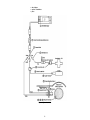
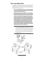
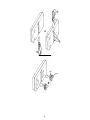
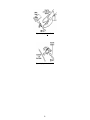
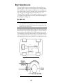
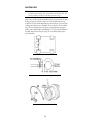
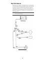
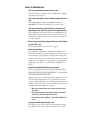
INSTALLATION MANUAL
Product #’s: 8140, 8143, 8146, 8150
1. CONTENTS OF PACKAGE
1.
2.
3.
4.
5.
6.
7.
8.
9.
10.
11.
12.
13.
14.
15.
16.
17.
18.
19.
DriveRight display
Battery (CR123 3V Lithium)
Coiled cable extension
Harness cable
Visor clip
Mounting bracket
6-32 x 1/2” flat head machine screw (3)
#6 x 1/2” flat head self-tapping screw (3)
#6 split lock washer (6)
#6 flat washer (6)
6-32 nut (3)
Right angle adapter bracket
#6 x 1/2” pan head self-tapping screw (3)
Double-sided foam tape (2 each)
VELCRO® tape (2 pair)
Red +12v wire with fuseholder (22 AWG)
Fuse (3AG 1-1/4” x 1/4”, .25A, SLO-BLO)
Black ground wire (22 AWG)
Spade terminal (2)
20.
21.
22.
23.
24.
25.
26.
27.
28.
29.
30.
31.
32.
(5)
33.
34.
35.
36.
37.
Figure 1: DriveRight Parts
1
In-line splice (3)
Butt splice (26-22AWG or 24-20AWG) (5)
Magnet
Magnet mount
Large tie wrap (2)
Speed sensor with leads
1/2” brass hex nut (2)
3/8” flat washer
3/8” internal tooth lock washer
Sensor mounting bracket
Support bracket
#14 x 3/4” self-tapping screw (4)
1/4-20 x 3/4” hex head machine screw
1/4” split lock washer (5)
1/4” flat washer (5)
1/4“-20 nut (5)
Split flexible tubing
Small tie wraps (8)
2. INTRODUCTION
The Davis DriveRight™ is designed to allow straightforward installation. The specific details of installation vary by vehicle model and year. This manual provides
general instructions sufficient to guide a professional installer or knowledgeable,
experienced individual through a successful installation. Please read or at least skim
the entire manual before beginning the installation. Read and understand each step
thoroughly before starting that step. Your DriveRight includes a limited number of
extra parts. In this manual, parts will be referred to by their item numbers shown in
Figure 1.
WARNING: The magnet supplied with the DriveRight is extremely strong and will de-magnetize
ATM cards, credit cards, etc., if brought in contact. It may also affect other sensitive
electronic equipment.
PROFESSIONAL VS. DO-IT-YOURSELF INSTALLATION
Davis Instruments strongly recommends that the DriveRight be installed by ASE
(Automotive Service Excellence) certified technicians or professional automotive
mechanics. As with any installation of an automotive accessory, the installer must
make a series of decisions, in this case decisions such as where and how the sensor
and brackets are mounted, where holes are drilled, how wires are routed, where to
locate unswitched +12V and ground and so on. These decisions are best made by a
knowledgeable and experienced professional. Poor decisions may damage your vehicle or cause accidents or injuries.
If you select professional installation, use the procedure described in “Initial Test”
on page 18 to verify the work done.
WARNING: Working beneath your vehicle and installing the DriveRight may be hazardous.
Improper installation may damage your vehicle and cause accidents and/or injuries. If
you are uneasy about installing your unit please have a qualified professional complete
the installation. Davis specifically disclaims any liability for injury or loss resulting
from the installation or use of the DriveRight.
GETTING READY
Before installing your DriveRight:
• You may need to raise the vehicle in order for you to work under it. Always use
safety stands when working on or under any vehicle that is supported by only a
jack.
• You may need the following tools or equivalent. Additional tools may be
required depending on your specific installation.
• drill and drill bits, 1/8” to 5/16” (3 to 8mm)
• multimeter and/or test light
• hacksaw
• adjustable wrenches
• vise
• metal forming tools
• crimp tools
• wire cutter
2
• wire stripper
• various screwdrivers
• pliers
Figure 2: Typical Installation
3
3. PLANNING YOUR INSTALLATION
Figure 2 illustrates the installation of the DriveRight. The sensor, sensor magnet
and associated brackets mount underneath your vehicle. Figure 12 on page 11 is a
sketch of a typical rear wheel drive sensor installation while Figure 17 on page 13 is
a sketch of a typical front wheel drive sensor installation. The sensor leads run
under the vehicle and into the vehicle cabin where they connect to the DriveRight
display. The DriveRight display also requires unswitched +12V and ground connections to your vehicle’s electrical system.
Before you begin the actual hands-on installation of your DriveRight, please plan
out your installation by thinking through the following points. This will save you
time, frustration, and parts.
• Determine how and where you want to mount the DriveRight display within the
vehicle cabin.
NOTE: Safe driving requires that the driver’s attention be focused on the road. Please install
your DriveRight in a location which minimizes distractions to the driver.
• Find a single point in the vehicle cabin where you can bring together the leads
of the harness cable, the sensor leads, and the +12V and ground wires.
• Determine how you will route the harness cable to the DriveRight display.
• Locate your fusebox and find a source of UNSWITCHED +12V NOT USED FOR
SAFETY RELATED EQUIPMENT.
NOTE: “Unswitched +12V” means +12V not switched off by the ignition key. The
DriveRight consumes negligible power (nominally, 5mA) and will not run down
your vehicle’s battery. The lithium 3.0V battery inside the DriveRight is not
rechargeable and is not charged by the vehicle’s battery.
• Locate a ground point to attach a ground wire spade terminal.
• Locate a feedthrough into the vehicle cabin through which you can bring the
two sensor leads and the +12V and ground wires if your fusebox is in your
engine compartment.
• IF YOU HAVE A FRONT WHEEL DRIVE VEHICLE, decide whether you will place the
sensor magnet on either the left or right side in-board constant velocity (CV)
joint hub.
• IF YOU HAVE A REAR WHEEL DRIVE VEHICLE, decide where on the driveshaft
within 12” (30cm) of the transmission you will place the sensor magnet.
• Decide how you will attach the brackets so that the sensor is within 3/8” - 5/8”
(10-16mm) of the magnet. How will you form the brackets to fit? What holes
will you use or drill to mount the bracket? Do these holes pierce the vehicle
floor? Where? (DO NOT USE FLUID RETAINING BOLTS AS MOUNTING POINTS.)
• Decide how you will route the wires from the sensor to a feedthru into the
vehicle cabin.
• THE WIRES SHOULD BE ROUTED AT LEAST 12” (30CM) AWAY FROM SPARKPLUG
WIRES, THE COIL, AND THE ALTERNATOR. AVOID LOOPS, COILS, AND FOLDS
SHOULD TO PREVENT UNWANTED INTERFERENCE THAT MIGHT RESULT IN
ERRONEOUS READINGS.
4
Step 1. DISPLAY MOUNTING OPTIONS
The DriveRight comes with the hardware necessary for a variety of display mounting options. The long harness cable (4) included with the DriveRight allows you to
install the display where you want it. You may, at your option, use the coiled cable
extension (3) for even greater convenience.
• Use the visor clip (5) to mount your display on a visor or door pocket. Install the
clip on the top or bottom of the display to orient the display as you wish (Figure
4). Push the clip in until the 3rd bump engages.
• Mount your display to the dash or center console. Choose a location and decide
how you want to mount the display: directly to the surface or using the mounting
bracket (6) and right angle adapter bracket (12). Then, decide how you want to
attach the display or the brackets: using VELCRO tape (15), double-sided foam
tape (14), or screws. Apply the two adhesive-backed loop tapes to the flats on the
back of the display (Figure 5) or to the back of the brackets. With the hook tapes
attached to the loop tapes, press adhesive backing of the hook tape onto your
selected mounting surface. Do not separate hook and loop tape for at least 24
hours after applying. Attach the mounting bracket to the right angle adaptor
bracket (12) with hardware provided as needed (Figure3). Mount the reversible
right angle adaptor bracket to desired location with hardware provided. Apply the
double-sided foam tape to mount the brackets if desired.
NOTE: For best results with foam tape or VELCRO, apply adhesive at room temperature of
68˚F (20˚C) or higher. Surface should be clean, dry and free of oils. Use clean wiping materials with a cleaner appropriate for your vehicle’s interior to free surface of
contaminates and allow to dry. Peel release liner from back of tape and apply. (Take
care not to touch the adhesive with your fingers.) If adhesive must be applied at temperatures lower than 68˚F (20˚C), warm substrate and the tape to elevate temperature prior to applying. This may help the bond cure. Allow 24 hours for full cure
before loading or cycling.
Figure 3: Bracket Mounting Options
5
Figure 4: Using the Visor Clip
Loops
Hooks
15 2x
Figure 5: Applying VELCRO
6
Step 2. +12V POWER AND GROUND CONNECTIONS
NOTE: Thinking ahead...In Step 5, you will bring the sensor leads, +12V wire, and ground wire to
a single point of your choice under the dash and connect them to the display harness cable.
Choose this single point now. The sensor leads must be led into the vehicle cabin. Usually
you can use an existing feedthru in the firewall. If your fusebox is in the engine compartment then you may also need a feedthru to bring the +12V and ground wires through into
the vehicle cabin.
The DriveRight requires an unswitched +12V connection to your vehicle and a
ground connection to the vehicle chassis. These connections are often most easily
made at your vehicle’s fusebox. A direct connection in your fusebox is best - some
vehicles have extra slots for accessories such as the DriveRight. You may need to buy
the proper termination for use with your vehicle’s fusebox - consult your dealer or
local auto parts store. Attach the termination or connector to the end of the red
+12V wire with fuseholder (16) and insert into your fusebox. Otherwise select an
unswitched wire exiting the fusebox that does not involve safety-related equipment such as headlights, brakes and so on. Possible candidate wires may include
the wires used for the cigarette lighter, dome light (before the switch), glove compartment light, clock, tail gate light and other convenience functions. The wire
used should be 22-18AWG or have the same diameter as the red +12V wire with
fuseholder. Use the in-line splice (20) to make the connection to the red +12V wire
with fuseholder (Figure 9). Trim off flush the stripped portion of the red wire. The
fuseholder should be in the vehicle cabin.
Figure 6: Making Unswitched +12V and Ground Connection Within Vehicle Cabin
7
A ground connection may be made be inserting the spade terminal (19) under the
head of a screw threaded into the vehicle chassis (Figure 8). Use a multimeter to
verify the ground connection to vehicle chassis. The fusebox mounting screws are
candidate connections. If a screw is not convenient, locate a ground wire that is
22-18AWG or has the same diameter as the black ground wire. Use an in-line splice
(20) to make the connection to the black ground wire.
Figure 7: Making Unswitched +12V and Ground Connection Outside Vehicle Cabin
8
Figure 8: Crimping the Spade Terminal
:
Figure 9: Splicing for Unswitched +12V
9
Step 3. SENSOR INSTALLATION
The sensor installation requires mounting a magnet on the drive shaft of a rear
wheel drive vehicle or on the in-board CV joint hub of a front wheel drive vehicle.
The reed switch sensor (25) is mounted on a bracket opposite to the magnet rotating on the drive shaft or in-board CV joint hub. The sensor detects the magnet as it
passes. The gap between the magnet mount and sensor must be 3/8” - 5/8”
(10-16mm) (Figure 11 and Figure 15). There should be a clearance zone of at least
3/4” (19mm) above the drive shaft or in-board CV joint hub where the magnet is
mounted (Figure 11 and Figure 15).
REAR WHEEL DRIVE
NOTE: Thinking ahead...Consider the mounting locations carefully. Are the attachment points
strong enough? What is behind any surface you want to drill into? Do not drill into your gas
tank or foot wells in the vehicle cabin or any location where wires might be present. Check
both sides of the surface before you drill.
A typical rear wheel drive installation is shown in Figure 12. Select a location on the
drive shaft within 12 inches (30cm) of the universal joint to account for vehicle suspension movement while driving (Figure 10). Install the magnet (22) in its mount
(23) using the large tie wrap (24) as shown in Figure 13. Loosely cinch the large tie
wrap around the drive shaft, with the magnet mount oriented as shown, so you can
adjust its final position after the sensor is installed. Do not cinch tight the tie wrap.
Figure 10: Positioning the Sensor (Rear Wheel Drive)
Figure 11: Determining Proper Clearances and Gap (Rear Wheel Drive)
10
Figure 12: Typical Installation (Rear Wheel Drive)
Figure 13: Installing the Magnet (Rear Wheel Drive)
11
FRONT WHEEL DRIVE
NOTE: Thinking ahead...Choose the in-board CV joint hub you want to use by looking at how you
can mount the sensor and how in Step 5 you will route the wires into vehicle cabin . Consider where feedthrus are and how you will make the connections in Step 6.
Select an in-board CV joint hub and install the magnet (22) in its mount (23) using
the large tie wrap (24) as shown in Figure 16. Loosely cinch the large tie wrap
around the CV joint, with the magnet mount oriented as shown, so you can adjust
its final position after the sensor is installed. Do not overlap boot. Do not cinch tie
wrap. Choose mounting locations for the sensor mounting bracket and support
bracket on the transaxle/engine assembly (Figure 17). Do not mount the bracket on
the vehicle chassis because of engine torque. Do not use fluid retaining bolts to
retian the brackets.
Figure 14: Positioning the Sensor (Front Wheel Drive)
Figure 15: Determining Proper Clearances and Gap (Front Wheel Drive)
Figure 16: Installing the Magnet (Front Wheel Drive)
12
Figure 17: Typical Installation (Front Wheel Drive, Engine Mount)
13
Step 4. SENSOR BRACKET INSTALLATION (CONTINUED)
The instructions below describe an optimal sensor bracket assembly. Due to the
variations in individual cars, you will need to adapt these instructions to fit the sensor bracket into whatever situation exists. As you do so, it is vital to insure that
THE SENSOR END PROTRUDES 3/4” (19mm) FROM THE SENSOR
MOUNTING BRACKET. See Figure 11 on page 10 or Figure 15 on page 12. In
addition, the brackets must not protrude below other parts on the vehicle underbody.
NOTE: At low speeds, excessive vehicle vibrations can cause erroneous readings.
REAR WHEEL DRIVE
Choose mounting locations for the sensor mounting bracket (29) and support
bracket (30). The support bracket reinforces the sensor mounting bracket against
vibration. Do not mount the brackets as shown in Figure 19. After installing the
brackets for the proper gap between the sensor tip and the magnet mount, adjust
the large tie wrap so that the magnet passes opposite the end of the sensor. Cinch tie
wrap tight against drive shaft. Check the alignment of the magnet mount with end
of sensor by spinning tires if possible.
FRONT WHEEL DRIVE
The support bracket reinforces the sensor mounting bracket against vibration. Do
not mount the brackets as shown in Figure 19. After installing the brackets for the
proper gap, adjust the large tie wrap so that the magnet passes opposite the end of
the sensor. Cinch tie wrap tight against CV joint hub. Check the alignment of the
magnet mount with end of sensor by spinning tires if possible.
Figure 18: Sensor Bracket Assembly
14
Figure 19: Wrong Way To Use Brackets
Step 5. WIRE ROUTING
Use the split flexible tubing (36) to protect the sensor leads from sensor up into the
vehicle cabin. Use the small tie wraps (37) to hold the leads against the underbody
of your vehicle. The tubing can be cut into pieces and used where the wires may rub
against sharp points or edges and where the leads are tie wrapped to the underbody.
Tubing can also be used where the leads are particularly exposed. If a vehicle wire
bundle is readily accessible, route the sensor leads along this wire bundle. The sensor leads should be routed at least 12” (30 cm) away from sparkplug wires, the coil,
and the alternator. Loops, coils, and folds should be avoided in order to avoid creating unwanted interference that might result in erroneous readings.
Figure 20: Protecting the Wires
15
Step 6. WIRE CONNECTIONS
Make final connections (Figure 21). Use the butt splices (21) to connect the white
sensor lead to harness cable white wire, the black sensor lead to harness cable black
wire, and the red +12V wire w/ fuseholder to harness cable red wire (Figure 22).
Stripped wire ends should be 3/16”- 1/4” (5-6 mm). Use an in-line splice to connect the black ground wire to the black sensor lead near the butt splice (Figure 23).
Install fuse (17) in fuseholder. Use a small tie wrap to secure and protect the connections under the dash.
CAUTION:If the connections are on the driver’s side, make sure the wires can not become entangled
in the vehicle pedals or driver’s feet.
Figure 21: Making Final Connections
16
Figure 22: Crimping the Butt Connectors
Figure 23: Splicing Ground Together
17
Step 7. INITIAL TEST
To check the installation of the DriveRight, follow the test procedure below.
NOTE: It is not necessary to enter a code in order to perform this test. DO NOT ENTER A CODE
UNTIL YOU READ THE USER’S MANUAL.
1. Insert the battery (2) into the display as shown in Figure 24. (If your battery is
already installed, you may need to press MODE to “wake up” the unit.)
Figure 24: Installing the Battery
The screen you should see is the current readings screen. The word “BAT”
should appear in the lower left corner, indicating that the unit is operating on
battery power.
Figure 25: Battery Indicator (Lower Left of Screen)
2. Press and hold MODE for 3-5 seconds until the last correct code screen appears.
If you have already used the display, you may see the tamper time screen instead.
If so press MODE once to display the last correct code screen.
Figure 26: Last Correct Code Screen
18
3. With the ignition off, insert the DriveRight display cable into the harness cable
connector and lock the connectors. To do this, you will need to grasp the display
cable just behind the plastic sheath covering the connector, as shown below.
Push the display cable in until it locks into place.
Figure 27: Connecting the Display Cable to the Harness Cable
NOTE: To disconnect the two cables, hold the plastic sheath on the display cable, as shown
below. Pull back until the two connectors separate.
Figure 28: Disconnecting the Display Cable and the Harness Cable
When the two cables are connected, the “BAT” should disappear, indicating that
the unit is drawing power from the vehicle’s battery. A dot may appear to the
right of where BAT was. This dot will be used to verify the magnet placement in
the next step.
19
4. Roll the car forward slowly so the driveshaft or CV joint hub complete at least
one complete revolution. You should perform this test while the vehicle is on the
ground and not on the stand. As the vehicle suspension takes up the weight of
the vehicle, the driveshaft and CV joint hub move. The sensor must be properly
aligned with the magnet in this normal condition.
The dot should appear and then disappear each time the magnet passes the sensor. If the dot does not flash as described, consult the Troubleshooting section.
Figure 29: Dot Position at Bottom of Screen
NOTE: The DriveRight come with sample data pre-programmed into the log so you can use all
of the unit’s features immediately. As you use the unit, this data will automatically be
over-written by new data.
5. Road test the DriveRight by driving around and observing the readings. You will
need two people for this test: one to drive and the other to operate and read the
DriveRight.
Before the DriveRight will read correctly, you must calibrate the unit. Follow the
instructions in the User’s Manual for instructions on calibrating the DriveRight.
20
4. TROUBLESHOOTING GUIDE
A successful installation requires the following.
1. White sensor wire is connected to the white wire of the harness cable.
Crimp connector must be properly crimped.
2. Black sensor wire is connected to the black wire of the harness cable.
Crimp connector must be properly crimped.
3. Sensor leads should be protected with split tubing and tie wrapped in place.
Wires should be routed at least 12” (30cm) away from sparkplug wires, the coil,
and the alternator. Loops, coils, and folds should be avoided in order to avoid
creating unwanted interference that might result in erroneous readings.
4. Unswitched +12V from your vehicle is connected to the red wire of the harness
cable.
• Fuse must be installed and unbroken.
• In-line splices and /or crimp connectors must be properly crimped.
• “BAT” does not appear on display when ignition is off and display is operating and plugged into harness cable.
5. Ground connection from your vehicle is connected to the black wire from the
sensor.
• In-line splice and spade terminal must be properly crimped.
• Screw head fastening the spade terminal must make contact to the vehicle’s metal chassis.
6. Sensor installation is completed as directed.
• Sensor and magnet location on driveshaft or inboard CV joint as directed.
• Magnet mount with magnet in place cinched tight and free to rotate.
• Magnet mount aligned with sensor tip and passing within 3/8” - 5/8 (1016 mm).
• Sensor tip protruding 3/4” (19 mm) beyond the sensor mounting bracket.
• Sensor bracket properly reinforced by support bracket against vibration.
• All fasteners properly installed and screwed down tight.
• No portion of sensor installation protruding below other nearby components under the vehicle.
7. Display is installed and tested as directed.
• Battery is installed, “BAT” is indicated on screen prior to connecting to harness cable.
• “BAT” disappears when display is plugged into harness cable with ignition
off.
• DOT (“.”) appears and disappears if wheels are rotated or vehicle moves
very slowly forward.
21
ANSWERS TO COMMON QUESTIONS
• “BAT” stays on when display is connected to harness cable.
The wire connections to the harness cable are probably not correct. Inspect
your wiring. See 1-5 on page 21.
• “BAT” comes on when ignition is turned off and display is plugged into harness
cable.
The DriveRight display is connected to switched +12V instead of
unswitched +12V. Connect to unswitched +12V. See Step 2 on page 7.
• “BAT” appears when display is connected to harness cable but flashes off
when dot appears. (See “Initial Test” on page 18 for a description of the dot.)
The black and white wires from the sensor are connected backwards to the
black and white wires of the harness cable or the ground connection to the
vehicle’s chassis is spliced to the white sensor wire. Inspect your wiring, see 1,
2, 3, and 5 on page 21.
• Dot does not appear when display is plugged into the harness cable and wheels
are rotated (“BAT” is off).
The sensor installation may be incorrect. See 6 on page 21.
• Speed is zero when driving.
It is possible that you simply have not calibrated the DriveRight (see the
User’s Guide for instructions.) If your speed remains zero, the sensor may not
be close enough to or properly aligned to the magnet mount. Inspect sensor
installation with vehicle resting on its wheels. Check positions of sensor tip and
magnet mount. If not aligned, see 6 on page 21. If sensor appears aligned
properly and speed remains zero, use “Sensor Wire Continuity Test” on
page 23.
• Speed reading is intermittent while driving at constant speeds.
The sensor mounting bracket may be interfering with the magnetic field.
MAKE SURE THE SENSOR END PROTRUDES 3/4” (19 mm) FROM
THE SENSOR MOUNTING BRACKET.
Otherwise, there may be too much movement in the driveshaft or in-board
CV joint causing the magnet mount to be too far from the sensor tip on
occasion, or the connections may be loose. To fix this problem, inspect sensor
installation with the vehicle resting on its wheels. Check positions of sensor tip
and magnet mount. If not aligned, see 6 on page 21.
• Move sensor and magnet mount closer to universal joint on rear wheel
drive vehicles.
• Check vertical alignment of sensor bracket if bracket is mounted on the
vehicle chassis, consider mounting bracket to engine.
• If the brackets are properly installed, use “Sensor Wire Continuity Test” on
page 23.
• Screen goes blank when attached to harness cable.
The display is going into “sleep” mode. This only only happens when the
unit is running on battery power. Inspect your wiring. See 1-5 on page 21.
• Knocking sounds are coming from under the vehicle.
The magnet is hitting the vehicle or mounting bracket while rotating. Inspect the
sensor installation and reinstall as needed. See “Sensor Installation” on page 10.
• Current Readings are zero but everything appears properly installed.
You may have loose or poor connections and/or a broken wire inside of wire
insulation. Use “Sensor Wire Continuity Test” on page 23 to locate problem
wiring. Tighten crimps and/or replace wire.
SENSOR WIRE CONTINUITY TEST
1. Unplug harness cable.
2. Use an multimeter or continuity tester to probe Pins 2 and 3 on the harness
connector.
•
•
•
•
Pin 1: Unswitched +12V
Pin 2: Sensor Signal
Pin 3: Ground
Pin 4: Unused
Figure 30: Position of Pins on Harness Connector
3. Roll vehicle forward.
Multimeter or continuity tester should indicate a short each time the magnet
passes the sensor tip. If so the sensor is operating properly
4. If no short is indicated, check the wiring carefully for breaks or loose
connections. Probe between the white wire of the harness cable as it enters the
butt connectors and Pin 2. Probe between the black wire of the harness cable as
it enters the butt connectors and Pin 3.
The multimeter or continuity tester should indicate a short. If so the harness
cable is unbroken.
5. Check the butt connectors carefully for loose connections by probing across the
butt splice for the white wires and then across the butt splice for the black
wires.
The multimeter or continuity tester should indicate a short. If so the butt connectors are properly crimped. If not, tighten crimps or replace crimps (two extra
butt connectors were provided with your DriveRight).
6. Check the sensor wires for nicks or other signs of damage, remove and replace
suspect sections, use 22 AWG UL1015 (105C) wire with 22-18 AWG insulated
(red) butt connectors available at your local hardware store.
5. WARRANTY & REPAIR INFORMATION
ONE YEAR LIMITED WARRANTY
We warrant our products to be free of defects in material and workmanship for the period of one year from
the date of original purchase. While we make every effort to carefully manufacture our products to the
highest standards of quality, occasionally parts may be found to be missing, defective, or damaged.
If you have a defective part, return the product to us, shipping charges pre-paid. Include proof of purchase
and a written explanation of the trouble. During the warranty period, we will, at our option, either repair or
replace the product free of charge.
This warranty does not cover damage due to improper installation or use, negligence, accident, or
unauthorized service, or to incidental or consequential damages beyond the Davis products themselves.
Implied warranties are limited in duration to the life of this limited warranty.
Some states do not allow limitations on how long an implied warranty lasts, or the exclusion or limitatioon
of incidental and consequential damages, so the above may not apply to you. This warranty gives you
specific legal rights. You may have other rights, which vary from state to state.
FCC PART 15 CLASS B REGISTRATION WARNING
This equipment has been tested and found to comply with the limits for a Class B digital device, pursuant
to Part 15 of the FCC Rules. These limits are designed to provide reasonable protection against harmful
interference in a residential installation. This equipment generates, uses, and can radiate radio frequency
energy and, if not installed and used in accordance with the instructions, may cause harmful interference to
radio communications.
However, there is no guarantee that interference will not occur in a particular installation. If this equipment
does cause harmful interference to radio or television reception, which can be determined by turning the
equipment on and off, the user is encouraged to try to correct the interference by one or more of the
following measures:
Reorient or relocate the receiving antenna.
Increase the separation between the equipment and receiver.
Connect the equipment into an outlet on a circuit different from that to which the receiver is
connected.
Consult the dealer or an experienced radio/TV technician for help.
Changes or modifications not expressly approved in writing by Davis Instruments
may void the user's authority to operate this equipment.
Product Number: 8140
Davis Instruments Part Number: 7395-043
DriveRight™
Rev. B Manual (8/21/98)
© Davis Instruments Corp. 1997. All rights reserved.
DriveRight is a trademark of Davis Instruments Corp., Hayward, CA.
VELCRO is a trademark of Velcro Industries, Manchester, NH.
24