1
MOTION CONTROLLERS
MT Developer2
Version 1
Setup Guidance
SAFETY PRECAUTIONS
(Read these precautions before using this product.)
Before using this product, please read this manual and the relevant manuals carefully and pay full
attention to safety to handle the product correctly. The precautions given in this manual are concerned
with this product only. Refer to the user’s manual of the CPU module to use for a description of the PLC
system safety precautions. In this manual, the safety precautions are classified into two levels:
"WARNING" and "CAUTION".
Indicates that incorrect handling may cause hazardous
conditions, resulting in death or severe injury.
Indicates that incorrect handling may cause hazardous
conditions, resulting in minor or moderate injury or
property damage.
Under some circumstances, failure to observe the precautions given under "CAUTION" may lead to
serious consequences.
Observe the precautions of both levels because they are important for personal and system safety.
Make sure that the end users read this manual and then keep the manual in a safe place for future
reference.
A-1
For Safe Operations
[Design Precautions]
● Configure safety circuits external to the programmable controller to ensure that the entire system
operates safely even when a fault occurs in the external power supply or the programmable
controller.
Failure to do so may result in an accident due to an incorrect output or malfunction.
(1) Configure external safety circuits, such as an emergency stop circuit, protection circuit, and
protective interlock circuit for forward/reverse operation or upper/lower limit positioning.
(2) The programmable controller stops its operation upon detection of the following status, and the
output status of the system will be as shown below.
• Turned off if the overcurrent or overvoltage protection of the power supply module is
activated.
• Held or turned off according to the parameter setting if the self-diagnostic function of the
CPU module detects an error such as a watchdog timer error.
(3) Also, all outputs may be turned on if an error occurs in a part, such as an I/O control part,
where the CPU module cannot detect any error. To ensure safety operation in such a case,
provide a safety mechanism or a fail-safe circuit external to the programmable controller. For a
fail-safe circuit example, refer to the user's manual of the CPU module to use.
(4) Outputs may remain on or off due to a failure of a component such as a relay and transistor in
an output circuit. Configure an external circuit for monitoring output signals that could cause a
serious accident.
● In an output circuit, when a load current exceeding the rated current or an overcurrent caused by a
load short circuit flows for a long time, it may cause smoke and fire.
To prevent this, configure an external safety circuit, such as a fuse.
● Configure a circuit so that the programmable controller is turned on first and then the external
power supply. If the external power supply is turned on first, an accident may occur due to an
incorrect output or malfunction.
● For the operating status of each station after a communication failure, refer to manuals relevant to
the network. Incorrect output or malfunction due to a communication failure may result in an
accident.
● When connecting an external device with a CPU module or intelligent function module to modify
data of a running programmable controller, configure an interlock circuit in the program to ensure
that the entire system will always operate safely. For other forms of control (such as program
modification, parameter change, forced output, or operating status change) of a running
programmable controller, read the relevant manuals carefully and ensure that the operation is safe
before proceeding. Improper operation may damage machines or cause accidents.
● Especially, when a remote programmable controller is controlled by an external device, immediate
action cannot be taken if a problem occurs in the programmable controller due to a communication
failure. To prevent this, configure an interlock circuit in the program, and determine corrective
actions to be taken between the external device and CPU module in case of a communication
failure.
A-2
● Do not write any data to the "system area" and "write-protect area" of the buffer memory in the
module. Also, do not use any "use prohibited" signals as an output signal from the CPU module to
each module. Doing so may cause malfunction of the programmable controller system. For the
"system area", "write-protect area", and the "use prohibited" signals, refer to the user's manual for
the module used.
● If a communication cable is disconnected, the network may be unstable, resulting in a
communication failure of multiple stations. Configure an interlock circuit in the program to ensure
that the entire system will always operate safely even if communications fail. Failure to do so may
result in an accident due to an incorrect output or malfunction.
● To maintain the safety of the programmable controller system against unauthorized access from
external devices via the network, take appropriate measures. To maintain the safety against
unauthorized access via the Internet, take measures such as installing a firewall.
● Configure safety circuits external to the programmable controller to ensure that the entire system
operates safely even when a fault occurs in the external power supply or the programmable
controller.
Failure to do so may result in an accident due to an incorrect output or malfunction.
(1) Machine home position return is controlled by two kinds of data: a home position return
direction and a home position return speed. Deceleration starts when the near-point dog signal
turns on. If an incorrect home position return direction is set, motion control may continue
without deceleration. To prevent machine damage caused by this, configure an interlock circuit
external to the programmable controller.
(2) When the module detects an error, the motion slows down and stops or the motion suddenly
stops, depending on the stop group setting in parameter. Set the parameter to meet the
specifications of a positioning control system. In addition, set the home position return
parameter and positioning data within the specified setting range.
(3) Outputs may remain on or off, or become undefined due to a failure of a component such as
an insulation element and transistor in an output circuit, where the module cannot detect any
error. In a system that the incorrect output could cause a serious accident, configure an
external circuit for monitoring output signals.
● If safety standards (ex., robot safety rules, etc.,) apply to the system using the module, servo
amplifier and servomotor, make sure that the safety standards are satisfied.
● Construct a safety circuit externally of the module or servo amplifier if the abnormal operation of
the module or servo amplifier differs from the safety directive operation in the system.
● Do not remove the SSCNET cable while turning on the control circuit power supply of Multiple
CPU system and servo amplifier. Do not see directly the light generated from SSCNET
connector of the module or servo amplifier and the end of SSCNET cable. When the light gets
into eyes, you may feel something wrong with eyes. (The light source of SSCNET complies with
class1 defined in JISC6802 or IEC60825-1.)
A-3
[Design Precautions]
● Do not install the control lines or communication cables together with the main circuit lines or
power cables. Keep a distance of 100 mm or more between them. Failure to do so may result in
malfunction due to noise.
● During control of an inductive load such as a lamp, heater, or solenoid valve, a large current
(approximately ten times greater than normal) may flow when the output is turned from off to on.
Therefore, use a module that has a sufficient current rating.
● After the CPU module is powered on or is reset, the time taken to enter the RUN status varies
depending on the system configuration, parameter settings, and/or program size.
Design circuits so that the entire system will always operate safely, regardless of the time.
● Do not power off the programmable controller or do not reset the CPU module during the setting
registration. Doing so will make the data in the flash ROM undefined. The data need to be set in
the buffer memory and to be written to the flash ROM again. Doing so may cause malfunction or
failure of the module.
● Reset the CPU module after changing the parameters. Failure to do so may cause malfunction
because the previous parameter settings remain in the module.
● When changing the operating status of the CPU module from external devices (such as remote
RUN/STOP), select "Do Not Open by Program" for "Opening Method" in the module parameters. If
"Open by Program" is selected, an execution of remote STOP causes the communication line to
close.
Consequently, the CPU module cannot reopen the communication line, and external devices
cannot execute the remote RUN.
[Installation Precautions]
● Shut off the external power supply (all phases) used in the system before mounting or removing
the module. Failure to do so may result in electric shock or cause the module to fail or malfunction.
A-4
[Installation Precautions]
● Use the programmable controller in an environment that meets the general specifications in the
manual "Safety Guidelines" included in the base unit. Failure to do so may result in electric shock,
fire, malfunction, or damage to or deterioration of the product.
● To mount a module, place the concave part(s) located at the bottom onto the guide(s) of the base
unit, and push in the module until the hook(s) located at the top snaps into place. Incorrect
mounting may cause malfunction, failure, or drop of the module.
● When using the programmable controller in an environment of frequent vibrations, fix the module
with a screw.
● Tighten the screws within the specified torque range. Undertightening can cause drop of the
screw, short circuit, or malfunction. Overtightening can damage the screw and/or module, resulting
in drop, short circuit, or malfunction.
● When using an extension cable, connect it to the extension cable connector of the base unit
securely. Check the connection for looseness. Poor contact may cause incorrect input or output.
● When using an SD memory card, fully insert it into the memory card slot. Check that it is inserted
completely. Poor contact may cause malfunction.
● Securely insert an extended SRAM cassette into the cassette connector of a CPU module.
After insertion, close the cassette cover and check that the cassette is inserted completely. Poor
contact may cause malfunction.
● Do not directly touch any conductive parts and electronic components of the module, SD memory
card, extended SRAM cassette, or connector. Doing so may cause malfunction or failure of the
module.
[Wiring Precautions]
● Shut off the external power supply (all phases) used in the system before installation and wiring.
Failure to do so may result in electric shock or damage to the product.
● After installation and wiring, attach the included terminal cover to the module before turning it on
for operation. Failure to do so may result in electric shock.
A-5
[Wiring Precautions]
● Individually ground the FG and LG terminals of the programmable controller with a ground
resistance of 100 ohm or less. Failure to do so may result in electric shock or malfunction.
● Use applicable solderless terminals and tighten them within the specified torque range.
If any spade solderless terminal is used, it may be disconnected when the terminal screw comes
loose, resulting in failure.
● Check the rated voltage and signal layout before wiring to the module, and connect the cables
correctly. Connecting a power supply with a different voltage rating or incorrect wiring may cause
fire or failure.
● Connectors for external devices or coaxial cables must be crimped or pressed with the tool
specified by the manufacturer, or must be correctly soldered. Incomplete connections may cause
short circuit, fire, or malfunction.
● Securely connect the connector to the module. Poor contact may cause malfunction.
● Do not install the control lines or communication cables together with the main circuit lines or
power cables. Keep a distance of 100 mm or more between them. Failure to do so may result in
malfunction due to noise.
● Place the cables in a duct or clamp them. If not, dangling cable may swing or inadvertently be
pulled, resulting in damage to the module or cables or malfunction due to poor contact. Do not
clamp the extension cables with the jacket stripped.
● Check the interface type and correctly connect the cable. Incorrect wiring (connecting the cable to
an incorrect interface) may cause failure of the module and external device.
● Tighten the terminal screws or connector screws within the specified torque range.
Undertightening can cause drop of the screw, short circuit, fire, or malfunction. Overtightening can
damage the screw and/or module, resulting in drop, short circuit, fire, or malfunction.
● When disconnecting the cable from the module, do not pull the cable by the cable part. For the
cable with connector, hold the connector part of the cable. For the cable connected to the terminal
block, loosen the terminal screw. Pulling the cable connected to the module may result in
malfunction or damage to the module or cable.
● Prevent foreign matter such as dust or wire chips from entering the module. Such foreign matter
can cause a fire, failure, or malfunction.
● A protective film is attached to the top of the module to prevent foreign matter, such as wire chips,
from entering the module during wiring. Do not remove the film during wiring.
Remove it for heat dissipation before system operation.
● Mitsubishi programmable controllers must be installed in control panels. Connect the main power
supply to the power supply module in the control panel through a relay terminal block. Wiring and
replacement of a power supply module must be performed by qualified maintenance personnel
with knowledge of protection against electric shock. For wiring, refer to the MELSEC iQ-R Module
Configuration Manual.
A-6
[Wiring Precautions]
● For Ethernet cables to be used in the system, select the ones that meet the specifications in the
MELSEC iQ-R Ethernet/CC-Link IE User's Manual (Startup). If not, normal data transmission is not
guaranteed.
[Startup and Maintenance Precautions]
● Do not touch any terminal while power is on. Doing so will cause electric shock or malfunction.
● Correctly connect the battery connector. Do not charge, disassemble, heat, short-circuit, solder, or
throw the battery into the fire. Also, do not expose it to liquid or strong shock. Doing so may cause
the battery to generate heat, explode, ignite, or leak, resulting in injury or fire.
● Shut off the external power supply (all phases) used in the system before cleaning the module or
retightening the terminal screws, connector screws, or module fixing screws. Failure to do so may
result in electric shock or cause the module to fail or malfunction.
[Startup and Maintenance Precautions]
● When connecting an external device with a CPU module or intelligent function module to modify
data of a running programmable controller, configure an interlock circuit in the program to ensure
that the entire system will always operate safely. For other forms of control (such as program
modification, parameter change, forced output, or operating status change) of a running
programmable controller, read the relevant manuals carefully and ensure that the operation is safe
before proceeding. Improper operation may damage machines or cause accidents.
● Especially, when a remote programmable controller is controlled by an external device, immediate
action cannot be taken if a problem occurs in the programmable controller due to a communication
failure. To prevent this, configure an interlock circuit in the program, and determine corrective
actions to be taken between the external device and CPU module in case of a communication
failure.
● Do not disassemble or modify the modules. Doing so may cause failure, malfunction, injury, or a
fire.
● Use any radio communication device such as a cellular phone or PHS (Personal Handyphone
System) more than 25 cm away in all directions from the programmable controller.
Failure to do so may cause malfunction.
● Shut off the external power supply (all phases) used in the system before mounting or removing
the module. Failure to do so may cause the module to fail or malfunction.
A-7
[Startup and Maintenance Precautions]
● Tighten the screws within the specified torque range. Undertightening can cause drop of the
component or wire, short circuit, or malfunction. Overtightening can damage the screw and/or
module, resulting in drop, short circuit, or malfunction.
● After the first use of the product, do not mount/remove the module to/from the base unit, and the
terminal block to/from the module, and do not insert/remove the extended SRAM cassette to/from
the CPU module more than 50 times (IEC 61131-2 compliant) respectively.
Exceeding the limit of 50 times may cause malfunction.
● After the first use of the product, do not insert/remove the SD memory card to/from the CPU
module more than 500 times. Exceeding the limit may cause malfunction.
● Do not touch the metal terminals on the back side of the SD memory card. Doing so may cause
malfunction or failure.
● Do not touch the integrated circuits on the circuit board of an extended SRAM cassette.
Doing so may cause malfunction or failure.
● Do not drop or apply shock to the battery to be installed in the module. Doing so may damage the
battery, causing the battery fluid to leak inside the battery.
If the battery is dropped or any shock is applied to it, dispose of it without using.
● Startup and maintenance of a control panel must be performed by qualified maintenance
personnel with knowledge of protection against electric shock. Lock the control panel so that only
qualified maintenance personnel can operate it.
● Before handling the module, touch a conducting object such as a grounded metal to discharge the
static electricity from the human body.
Failure to do so may cause the module to fail or malfunction.
● Before testing the operation, set a low speed value for the speed limit parameter so that the
operation can be stopped immediately upon occurrence of a hazardous condition.
● Confirm and adjust the program and each parameter before operation.
Unpredictable movements may occur depending on the machine.
● When using the absolute position system function, on starting up, and when the module or
absolute value motor has been replaced, always perform a home position return.
● Before starting the operation, confirm the brake function.
● Do not perform a megger test (insulation resistance measurement) during inspection.
● After maintenance and inspections are completed, confirm that the position detection of the
absolute position detection function is correct.
● Lock the control panel and prevent access to those who are not certified to handle or install electric
equipment.
A-8
[Operating Precautions]
● When changing data and operating status, and modifying program of the running programmable
controller from an external device such as a personal computer connected to an intelligent function
module, read relevant manuals carefully and ensure the safety before operation. Incorrect change
or modification may cause system malfunction, damage to the machines, or accidents.
● Do not power off the programmable controller or reset the CPU module while the setting values in
the buffer memory are being written to the flash ROM in the module. Doing so will make the data
in the flash ROM undefined. The values need to be set in the buffer memory and written to the
flash ROM again. Doing so also can cause malfunction or failure of the module.
● Note that when the reference axis speed is specified for interpolation operation, the speed of the
partner axis (2nd, 3rd, or 4th axis) may exceed the speed limit value.
● Do not go near the machine during test operations or during operations such as teaching. Doing
so may lead to injuries.
[Disposal Precautions]
● When disposing of this product, treat it as industrial waste.
● When disposing of batteries, separate them from other wastes according to the local regulations.
For details on battery regulations in EU member states, refer to the MELSEC iQ-R Module
Configuration Manual.
[Transportation Precautions]
● When transporting lithium batteries, follow the transportation regulations. For details on the
regulated models, refer to the MELSEC iQ-R Module Configuration Manual.
● The halogens (such as fluorine, chlorine, bromine, and iodine), which are contained in a fumigant
used for disinfection and pest control of wood packaging materials, may cause failure of the
product.
Prevent the entry of fumigant residues into the product or consider other methods (such as heat
treatment) instead of fumigation.
The disinfection and pest control measures must be applied to unprocessed raw wood.
A-9
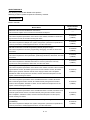
REVISIONS
The manual number is given on the bottom left of the back cover.
Print Date
Manual Number
Revision
Jan.,2008
Jul.,2008
IB(NA)-0300142-A First edition
IB(NA)-0300142-B [Correction]
SAFETY PRECAUTIONS, ABOUT MANUALS, OVERVIEW, OPERATING
ENVIRONMENT, SYSTEM CONFIGURATION, SETTING THE SSC
INTERFACE BOARD, COMMUNICATION DRIVER INSTALLATION
PROCEDURE, TROUBLESHOOTING, WARRANTY
Jan.,2009 IB(NA)-0300142-C [Correction]
SAFETY PRECAUTIONS, ABOUT MANUALS, OVERVIEW, OPERATING
ENVIRONMENT, SYSTEM CONFIGURATION, PRECAUTIONS,
TROUBLESHOOTING, APPENDICES, WARRANTY
Jul.,2009 IB(NA)-0300142-D [Correction]
ABOUT MANUALS, OVERVIEW, OPERATING ENVIRONMENT, SYSTEM
CONFIGURATION, TROUBLESHOOTING
May.,2010 IB(NA)-0300142-E [Correction]
SAFETY PRECAUTIONS, OPERATING ENVIRONMENT, PRECAUTION,
TROUBLESHOOTING, APPENDICES
Sep.,2010 IB(NA)-0300142-F [Correction]
OPERATING ENVIRONMENT, SYSTEM CONFIGURATION,
COMMUNICATION DRIVER INSTALLATION PROCEDURE,
TROUBLESHOOTING, APPENDICES
Nov,2011 IB(NA)-0300142-G [Correction]
SAFETY PRECAUTIONS, ABOUT MANUALS, OVERVIEW, OPERATING
ENVIRONMENT, SYSTEM CONFIGURATION, SETTING THE SSC
INTERFACE BOARD, COMMUNICATION DRIVER INSTALLATION
PROCEDURE, TROUBLESHOOTING, APPENDICES
Apr.,2012 IB(NA)-0300142-H [Correction]
ABOUT MANUALS, OVERVIEW, OPERATING ENVIRONMENT, SYSTEM
CONFIGURATION, APPENDICES
May.,2012 IB(NA)-0300142-J [Correction]
SAFETY PRECAUTIONS, APPENDICES, WARRANTY
Sep.,2012 IB(NA)-0300142-K [Correction]
ABOUT MANUALS, APPENDICES
Oct.,2012 IB(NA)-0300142-L [Correction]
TROUBLESHOOTING, APPENDICES
Mar.,2013
Jun.,2013
IB(NA)-0300142-M [Correction]
OVERVIEW, OPERATING ENVIRONMENT, SYSTEM CONFIGURATION,
APPENDICES
IB(NA)-0300142-N [Correction]
OPERATING ENVIRONMENT, SYSTEM CONFIGURATION, SETTING THE
SSC INTERFACE BOARD, COMMUNICATION DRIVER INSTALLATION
PROCEDURE, TROUBLESHOOTING, APPENDICES
A -10
Print Date
Sep.,2013
Feb.,2014
Jun.,2014
Manual Number
Revision
IB(NA)-0300142-P [Correction]
OVERVIEW, OPERATING ENVIRONMENT, TROUBLESHOOTING,
APPENDICES
IB(NA)-0300142-Q [Correction]
OPERATING ENVIRONMENT, SYSTEM CONFIGURATION, SETTING THE
SSC INTERFACE BOARD, COMMUNICATION DRIVER INSTALLATION
PROCEDURE, TROUBLESHOOTING, APPENDICES
IB(NA)-0300142-R [Correction]
OVERVIEW, OPERATING ENVIRONMENT, SYSTEM CONFIGURATION,
COMMUNICATION DRIVER INSTALLATION PROCEDURE,
TROUBLESHOOTING, APPENDICES
This manual confers no industrial property rights or any rights of any other kind, nor does it confer any
patent licenses. Mitsubishi Electric Corporation cannot be held responsible for any problems involving
industrial property rights which may occur as a result of using the contents noted in this manual.
© 2008 Mitsubishi Electric Corporation
A - 11
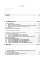
CONTENTS
SAFETY PRECAUTIONS ·····················································································································
REVISIONS···········································································································································
CONTENTS ··········································································································································
ABOUT MANUALS ·······························································································································
A-- 1
A-10
A-12
A-14
1. OVERVIEW ····························································································································· 1- 1 to 1-2
1.1 Overview······································································································································· 1-- 1
1.2 Features ······································································································································· 1-- 2
2. OPERATING ENVIRONMENT ······························································································ 2- 1 to 2- 3
2.1 Operating Environment ················································································································ 2-- 1
2.2 Use Conditions ····························································································································· 2-- 2
3. SYSTEM CONFIGURATION ································································································· 3- 1 to 3- 8
3.1 System Configuration ····················································································································· 3-- 1
3.1.1 When using R32MTCPU/R16MTCPU··················································································· 3-- 1
3.1.2 When using Q173D(S)CPU/Q172D(S)CPU/Q170MSCPU/Q170MSCPU-S1/Q170MCPU·· 3-- 2
3.1.3 When using Q173HCPU/Q172HCPU/Q173CPU(N)/Q172CPU(N) ······································ 3-- 3
3.2 Component List ···························································································································· 3-- 8
4. SETTING THE SSC INTERFACE BOARD ··········································································· 4- 1 to 4- 2
4.1 Setting the A10BD-PCF Interface Board······················································································ 4-- 1
5. COMMUNICATION DRIVER INSTALLATION PROCEDURE············································· 5- 1 to 5-19
5.1 USB Driver Installation Procedure ·······························································································
®
5.1.1 Precautions for using USB communication in Windows XP················································
®
5.1.2 Precautions for using USB communication in Windows Vista ············································
®
5.1.3 Precautions for using USB communication in Windows 7/Windows® 8/Windows® 8.1 ······
5.2 Updating the USB Driver ···············································································································
5.3 SSCNET Driver Installation Procedure ·························································································
®
5.3.1 Precautions for using SSCNET communication in Windows XP ·········································
®
5.3.2 Precautions for using SSCNET communication in Windows Vista ······································
5.3.3 Precautions for using SSCNET communication in Windows® 7·············································
5.3.4 Precautions for using SSCNET communication in Windows® 8/Windows® 8.1 ·····················
5-- 1
5-- 1
5-- 3
5-- 6
5-10
5-14
5-14
5-15
5-16
5-16
6. PRECAUTIONS ······················································································································ 6- 1 to 6-1
6.1 Uninstallation of SW6RN-SNETP or SW3RN-SNETP··································································· 6-- 1
6.2 Finding Ethernet Built-in Type CPU on the Network ···································································· 6-- 1
7. TROUBLESHOOTING············································································································7- 1 to 7-20
7.1 During USB Communication, Communication Error Occurred and Communication Is Not
Recovered from Error···················································································································
7.2 Project Cannot Be Saved or Read ·······························································································
7.3 Sampling Omission May Occur on the Digital Oscilloscope ························································
7.4 Digital Oscilloscope Cannot Be Started ·······················································································
A -12
7-- 1
7-- 1
7-- 2
7-- 3
7.5 The SSCNET Communication Manager of SW6RN-SNETP Displays "Shared Memory
Connection Error" ·························································································································
7.6 During Communication, "Can not allocate Share memory" Error Occurs····································
7.7 When SW3RN-SNETP is Started, "Not enough memory" Error Occurs······································
7.8 During USB Communication, the USB Driver Cannot Be Installed or Communication
Error Occurs·································································································································
7.9 USB communication fails with Windows Vista®/Windows® 7/Windows® 8/Windows® 8.1···········
7.10 MR Configurator Fails to Be Started from MT Developer2 (Linkage Function) ····························
7.11 Operation when Using a Program Data, Created with the Japanese Edition
in the English Edition ····················································································································
7.12 When Installation does not Complete or Warning Dialog Boxes are Displayed···························
7.13 A Dialog Box is Displayed after an Installer··················································································
7.14 When the TCP/IP Communication cannot be Established or
the Simulation Function cannot be Started···················································································
7.15 Start the Unexpected Auxiliary Screen in MT Developer2 ···························································
7-- 3
7-- 4
7-- 4
7-- 5
7-- 6
7-12
7-13
7-14
7-16
7-17
7-20
APPENDICES····················································································································· APP- 1 to APP-5
APPENDIX 1 Added Functions········································································································ APP-- 1
TRADEMARKS
WARRANTY
A -13
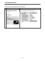
ABOUT MANUALS
The following manuals are related to this product.
Referring to this list, please request the necessary manuals.
Related Manuals
Motion controller
Manual Number
Manual Name
(Model Code)
MELSOFT MT Works2 Installation Instructions
This document explains how to install and uninstall MT Developer2.
MELSEC iQ-R Motion Controller User's Manual
This manual explains specifications of the Motion CPU modules, SSCNET III cables and
Synchronous encoder, and trouble shooting and others.
MELSEC iQ-R Motion Controller Programming Manual (Common)
This manual explains the Multiple CPU system configuration, performance specifications,
common parameters, auxiliary/applied functions, error lists and others.
MELSEC iQ-R Motion Controller Programming Manual (Program Design)
This manual explains the functions, programming, debugging, error lists for Motion SFC
and others.
MELSEC iQ-R Motion Controller Programming Manual (Positioning Control)
This manual explains the servo parameters, positioning instructions, device lists, error lists
and others.
MELSEC iQ-R Motion Controller Programming Manual (Advanced Synchronous Control)
This manual explains the dedicated instructions to use the synchronous control by
synchronous control parameters, device lists, error lists and others.
——
IB-0300235
(1XB002)
IB-0300237
(1XB004)
IB-0300239
(1XB006)
IB-0300241
(1XB008)
IB-0300243
(1XB010)
Q173D(S)CPU/Q172D(S)CPU Motion controller User's Manual
This manual explains specifications of the Motion CPU modules, Q172DLX Servo external
signal interface module, Q172DEX Synchronous encoder interface module, Q173DPX
Manual pulse generator interface module, Power supply modules, Servo amplifiers,
IB-0300133
(1XB927)
SSCNET III cables and Synchronous encoder, and the maintenance/inspection for the
system, trouble shooting and others.
Q170MSCPU Motion controller User's Manual
This manual explains specifications of the Q170MSCPU Motion controller, Q172DLX
Servo external signal interface module, Q173DPX Manual pulse generator interface
module, Servo amplifiers, SSCNET III cables, and the maintenance/inspection for the
IB-0300212
(1XB962)
system, trouble shooting and others.
Q170MCPU Motion controller User's Manual
This manual explains specifications of the Q170MCPU Motion controller, Q172DLX Servo
external signal interface module, Q173DPX Manual pulse generator interface module,
Servo amplifiers, SSCNETIII cables, and the maintenance/inspection for the system,
IB-0300156
(1XB941)
trouble shooting and others.
Q173D(S)CPU/Q172D(S)CPU Motion controller Programming Manual
(COMMON)
This manual explains the Multiple CPU system configuration, performance specifications,
common parameters, auxiliary/applied functions, error lists and others.
A -14
IB-0300134
(1XB928)
Manual Number
Manual Name
(Model Code)
Q173D(S)CPU/Q172D(S)CPU Motion controller (SV13/SV22) Programming
Manual (Motion SFC)
This manual explains the functions, programming, debugging, error lists for Motion SFC
IB-0300135
(1XB929)
and others.
Q173D(S)CPU/Q172D(S)CPU Motion controller (SV13/SV22) Programming
Manual (REAL MODE)
This manual explains the servo parameters, positioning instructions, device lists, error lists
IB-0300136
(1XB930)
and others.
Q173D(S)CPU/Q172D(S)CPU Motion controller (SV22) Programming Manual
(VIRTUAL MODE)
This manual explains the dedicated instructions to use the synchronous control by virtual
main shaft, mechanical system program create mechanical module, servo parameters,
IB-0300137
(1XB931)
positioning instructions, device lists, error lists and others.
Q173DSCPU/Q172DSCPU Motion controller (SV22) Programming Manual
(Advanced Synchronous Control)
IB-0300198
This manual explains the dedicated instructions to use the synchronous control by
(1XB953)
synchronous control parameters, device lists, error lists and others.
Q173D(S)CPU/Q172D(S)CPU Motion controller Programming Manual
(Safety Observation)
This manual explains the details, safety parameters, safety sequence program
instructions, device lists and error lists and others for safety observation function by
IB-0300183
(1XB945)
Motion controller.
Q173HCPU/Q172HCPU Motion controller User's Manual
This manual explains specifications of the Motion CPU modules, Q172LX Servo external
signal interface module, Q172EX Serial absolute synchronous encoder interface module,
Q173PX Manual pulse generator interface module, Teaching units, Power supply
IB-0300110
(1XB910)
modules, Servo amplifiers, SSCNETIII cables, synchronous encoder cables and others.
Q173HCPU/Q172HCPU Motion controller Programming Manual
(COMMON)
This manual explains the Multiple CPU system configuration, performance specifications,
common parameters, auxiliary/applied functions and others.
IB-0300111
(1XB911)
Q173HCPU/Q172HCPU Motion controller (SV13/SV22) Programming Manual
(Motion SFC)
IB-0300112
This manual explains the functions, programming, debugging, error codes and others of
(1XB912)
the Motion SFC.
Q173HCPU/Q172HCPU Motion controller (SV13/SV22) Programming Manual
(REAL MODE)
This manual explains the servo parameters, positioning instructions, device list, error list
IB-0300113
(1XB913)
and others.
Q173HCPU/Q172HCPU Motion controller (SV22) Programming Manual
(VIRTUAL MODE)
This manual explains the dedicated instructions use to the synchronous control by virtual
main shaft, mechanical system program create mechanical module.
This manual explains the servo parameters, positioning instructions, device list, error list
and others.
A -15
IB-0300114
(1XB914)
Manual Number
Manual Name
(Model Code)
Q173HCPU/Q172HCPU Motion controller (SV43) Programming Manual
This manual explains the dedicated instructions to execute the positioning control by
Motion program of EIA language (G-code), the servo parameters, positioning instructions,
device list, error list and others.
IB-0300115
(1XB915)
Q173CPU(N)/Q172CPU(N) Motion controller User's Manual
This manual explains specifications of the Motion CPU modules, Q172LX Servo external
signal interface module, Q172EX Serial absolute synchronous encoder interface module,
Q173PX Manual pulse generator interface module, Teaching units, Power supply
IB-0300040
(1XB780)
modules, Servo amplifiers, SSCNET cables, synchronous encoder cables and others.
Q173CPU(N)/Q172CPU(N) Motion controller (SV13/SV22) Programming Manual
(Motion SFC)
IB-0300042
This manual explains the Multiple CPU system configuration, performance specifications,
(1XB781)
functions, programming, error codes and others of the Motion SFC.
Q173CPU(N)/Q172CPU(N) Motion controller (SV13/SV22) Programming Manual
(REAL MODE)
This manual explains the servo parameters, positioning instructions, device list, error list
IB-0300043
(1XB782)
and others.
Q173CPU(N)/Q172CPU(N) Motion controller (SV22) Programming Manual
(VIRTUAL MODE)
This manual explains the dedicated instructions use to the synchronous control by virtual
main shaft, mechanical system program create mechanical module.
IB-0300044
(1XB783)
This manual explains the servo parameters, positioning instructions, device list, error list
and others.
Q173CPU(N)/Q172CPU(N) Motion controller (SV43) Programming Manual
This manual explains the dedicated instructions to execute the positioning control by
IB-0300070
Motion program of EIA language (G-code).
This manual explains the Multiple CPU system configuration, performance specifications,
functions, programming, debugging, servo parameters, positioning instructions device list
and error list and others.
A -16
(1XB784)
1. OVERVIEW
1. OVERVIEW
1.1 Overview
This manual describes those items related to the setup of the Motion controller
programming software MT Works2.
In this manual, the following abbreviations are used.
Generic term/Abbreviation
MELSOFT MT Works2
Description
Package product of the Motion controller engineering environment
MT Developer2
MT Developer2
Programming software included in MELSOFT MT Works2
MR Configurator2
Servo support software included in MELSOFT MT Works2
MT Developer
Integrated start-up support software package for the Q series Motion controller
SW6RNC-GSVE
SW6RNC-GSVE
Integrated start-up support software package for the Q series Motion controller
MT Developer
SW3RNC-GSVE
Integrated start-up support software package for the A series Motion controller
SW6RN-SNETP
Communication system software package included in SW6RNC-GSVE
SW3RN-SNETP
Communication system software package included in SW3RNC-GSVE
MR Configurator
Servo support software package
MRZJW3-SETUP221E
Motion CPU or Motion controller
R32MTCPU/R16MTCPU/
Q173DSCPU/Q172DSCPU/Q170MSCPU/Q170MSCPU-S1
Q173DCPU/Q172DCPU/Q173DCPU-S1/Q172DCPU-S1/Q170MCPU
Q173HCPU/Q172HCPU/Q173HCPU-T/Q172HCPU-T/
Q173CPU/Q172CPU/Q173CPUN/Q172CPUN/Q173CPUN-T/Q172CPUN-T
Motion CPU module
R32MTCPU/R16MTCPU
R32MTCPU/R16MTCPU
MELSEC iQ-R Series Motion CPU module
Q173D(S)CPU/Q172D(S)CPU/
Q173DSCPU/Q172DSCPU/Q170MSCPU/Q170MSCPU-S1
Q170MSCPU/Q170MSCPU-S1/
Q173DCPU/Q172DCPU/Q173DCPU-S1/Q172DCPU-S1/Q170MCPU
Q170MCPU
Q Series Motion CPU module
Q173HCPU/Q172HCPU
Q173HCPU/Q172HCPU/Q173HCPU-T/Q172HCPU-T
Q Series Motion CPU module
Q173CPU(N)/Q172CPU(N)
Q173CPU/Q172CPU/Q173CPUN/Q172CPUN/Q173CPUN-T/Q172CPUN-T
Q Series Motion CPU module
Operating System software
General name for " SW10DNC-RMTFW, SW DNC-SV Q , SW RN-SV Q "
SV13
Operating system software for conveyor assembly use:
SW8DNC-SV13Q
SV22
SW8DNC-SV22Q
SV43
/SW6RN-SV22Q
Operating system software for the peripheral of machine tools:
SW7DNC-SV43Q
SV54
/SW6RN-SV13Q
Operating system software for automatic machinery use:
/SW5RN-SV43Q
Operating system software for the dedicated robot:
SW5RN-SV54Q
SSCNET
High speed serial communication between the Motion CPU and servo amplifier
A10BD-PCF
A10BD-PCF SSC I/F board
A30CD-PCF
A30CD-PCF SSC I/F card
11
1. OVERVIEW
1.2 Features
MT Works2 is programming software for configuring and maintaining a system
using the Motion controllers.
Offering the program design environment and maintenance environment, the
software can be used for various applications in all the phases of configuring a
Motion controller system (system design program development debugging
startup operation and maintenance).
In addition, work efficiency is increased, by the expanded functions and improved
operability, in all the system configuration phases.
12
2. OPERATING ENVIRONMENT
2. OPERATING ENVIRONMENT
2.1 Operating Environment
Item
Contents
®
Personal computer Windows supported personal computer
®
®
Microsoft Windows XP Service Pack: 2, 3
®
Windows XP Professional,
®
Windows XP Home Edition
®
®
Microsoft Windows Vista (32-bit) Service Pack: Up to 2
®
Windows Vista Enterprise,
®
Windows Vista Ultimate,
®
Windows Vista Business,
®
Windows Vista Home Premium,
®
Windows Vista Home Basic
®
®
Microsoft Windows 7 (32-bit/64-bit) Service Pack: Up to 1
®
Windows 7 Enterprise,
®
Windows 7 Ultimate,
OS
®
Windows 7 Professional,
Personal computer
®
Windows 7 Home Premium,
main body
®
Windows 7 Starter
®
®
Microsoft Windows 8 (32-bit/64-bit)
®
Windows 8 Enterprise,
®
Windows 8 Pro,
®
Windows 8
®
®
Microsoft Windows 8.1 (32-bit/64-bit)
®
Windows 8.1 Enterprise,
®
Windows 8.1 Pro,
®
Windows 8.1
®
®
Desktop PC: Intel Celeron Processor 2.8GHz or higher
CPU
®
®
Laptop PC: Intel Pentium M Processor 1.7GHz or higher
Required memory
1GB or more recommended (For 32-bit edition)
2GB or more recommended (For 64-bit edition)
®
Video card
®
Video card supporting Microsoft DirectX 9.0c or higher
When installing: Available hard disk space 3GB or more
Available hard disk space
When operating: Available virtual memory space 512MB or more
(Note-1)
3.5 inch (1.44MB) floppy disk drive
Disk drive
DVD-ROM supported disk drive
Monitor
Resolution 1024 x 768 pixels or higher
RS-232 port, USB port, Ethernet port
Communication interfaces
(Note-2)
SSC I/F card (A30CD-PCF)
(Note-1): Required when installing the operating system software from a floppy disk.
®
®
(Note-2): The 64-bit edition of Windows 7/Windows 8 is not supported.
®
The 32-bit/64-bit edition of Windows 8.1 is not supported.
POINT
MR Configurator2 is also installed simultaneously.
For the details of the MR Configurator2, refer to the "MR Configurator2 SW1DNC-MRC2 INSTALLATION GUIDE".
21
(Note-2)
, SSC I/F board (A10BD-PCF)
2. OPERATING ENVIRONMENT
CAUTION
®
(1) This product may not perform properly when the following functions are used under Windows XP, Windows
®
®
®
®
Vista , Windows 7, Windows 8, Windows 8.1.
®
Activating the application with Windows compatible mode.
Simplified user switch-over
Remote desktop
Large fonts (Detail settings of screen property)
DPI setting other than that of the normal size (Detail settings of screen property)
®
®
®
®
(2) In Windows Vista /Windows 7/Windows 8/Windows 8.1, log in as a user having User authority or higher.
Otherwise, you should have the administrator level to link to SoftGOT.
®
(3) The following functions cannot be used under Windows 7.
Windows XP Mode, Touch
®
®
(4) The following functions cannot be used under Windows 8/Windows 8.1.
Hyper-V, Modern UI Style, Touch
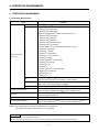
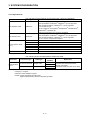
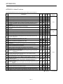
2.2 Use Conditions
(1) Supported Motion CPU/Motion controller OS list
Operating system software
Motion CPU module
SV13
SV22
SV43
SV54
R32MTCPU/R16MTCPU
Q173DSCPU/
Q172DSCPU
Q170MSCPU/
Q170MSCPU-S1
Q173DCPU(-S1)/
Q172DCPU(-S1)
Q170MCPU
Q173HCPU(-T)/
Q172HCPU(-T)
Q173CPUN-T/
Q173CPU(N)/
Q172CPUN-T/
Q172CPU(N)
: Supported
: Unsupported
(Note-1): The A series Motion CPUs are not supported by MT Developer2.
(Note-2): There is no OS class in R32MTCPU/R16MTCPU.
For convenience, this text explains on class column of SV13/22.
22
2. OPERATING ENVIRONMENT
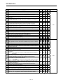
(2) Coexistence with SW6RNC-GSVE and SW3RNC-GSVE
The Operation availability when MT Developer2 is used (coexisted) with other
applications is shown in the table below. For the "Cannot be operated" start
and use either application. Do not start and use both applications.
Application
MT Developer2
Operation
SW6RNC-GSVE
SW3RNC-GSVE
Edit
Communication
(RS-232 and USB)
Communication
(SSCNET)
Edit
Communication
(RS-232 and USB)
(Note-2)
(Note-1)
Communication
(SSCNET)
(Note-2)
(Note-1)
Communication
(RS-232)
(Note-1)
(Note-1)
Communication
(SSCNET)
(Note-1)
(Note-1)
Edit
: Can be operated
:Cannot be operated
(Note-1): Both one-way communication and two-way simultaneous communication
cannot be operated.
(Note-2): Simultaneous communication can be operated.
23
3. SYSTEM CONFIGURATION
3. SYSTEM CONFIGURATION
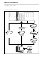
3.1 System Configuration
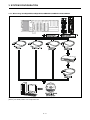
3.1.1 When using R32MTCPU/R16MTCPU
When Ethernet
connected with HUB
When Ethernet
connected directly
USB cable
Ethernet cable
(Cross cable)
(Note-1)
(Note-1)
Ethernet cable
(Straight cable)
HUB
Ethernet cable
(Straight cable)
MELSOFT MT Works2:
MT Developer2
MR Configurator2
31
3. SYSTEM CONFIGURATION
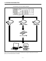
3.1.2 When using Q173D(S)CPU/Q172D(S)CPU/Q170MSCPU/Q170MSCPU-S1/Q170MCPU
(Note-1): Q173DCPU/Q172DCPU is not available.
(Note-2): For details, refer to "3.2 Component List".
32
3. SYSTEM CONFIGURATION
3.1.3 When using Q173HCPU/Q172HCPU/Q173CPU(N)/Q172CPU(N)
(1) Precautions for using a desktop personal computer
(Note-1): For details, refer to "3.2 Component List".
(Note-2): Q173HCPU/Q172HCPU is not available.
33
3. SYSTEM CONFIGURATION
(2) Precautions for using a laptop computer
(Note-1): For details, refer to "3.2 Component List".
(Note-2): We do not guarantee the proper operation of A30CD-PCF on all types of laptop personal computers.
(Note-3): Q173HCPU/Q172HCPU is not available.
34
3. SYSTEM CONFIGURATION
POINT
<When used in the USB/RS-232>
(1) If the USB cable is connected or disconnected or the multiple CPU
system is reset (or turned off and on) frequently during communication
of the Motion CPU, an unrecoverable communication error may occur.
Disconnect MT Works2 from the line(Note-1) whenever possible when
disconnecting or connecting the USB cable or resetting or turning on or
off the multiple CPU system.
If a communication error is not removed, disconnect the USB cable
completely and, after five seconds, connect it again. (Though an error
may occur during the first communication session after this operation,
the correct function is recovered at and after the second session.)
However, a communication error may not be removed even after the
above operation with some personal computer models. In this case,
reset the personal computer.
(2) A communication error may occur according to some combination of the
model of the personal computers and the USB cable and so on.
If this happens, repeat operation while referring to the displayed
message.
(3) If the baud rate of the serial port of the personal computer (interface on
the personal computer side) is changed for high speed communication,
communication may be unsuccessful or communication retries may
occur to result in slow communication, according to certain PC
performance.
If high speed communication is unsuccessful, decrease the baud rate.
(4) USB cable
The USB cable can be used with a USB driver.
If the USB cable is used, only one Motion CPU can be connected.
(Note-1): Disconnection from line (Offline state)
State where there is no communication with the Motion CPU
(Program or parameter reading/writing, monitoring and testing
are made in the online state.)
35
3. SYSTEM CONFIGURATION
POINT
<When used in the Ethernet>
(1) We do not guarantee the operation in the following connections.
Connection via the Internet (general public line)
Connection via a firewall device
Connection via the broadband rooter
Connection via the wireless LAN
(2) If the resume function, suspension setting, power-saving function or
stand-by mode is set in the personal computer used for communication
with the CPU, a communication error may occur.
Do not use these functions at the personal computer used for
communication with the CPU.
When used in the direct connection
(1) Communication can be made only by selecting the direct connection
(default) on the Transfer Setup screen of MT Works2.
It is not necessary to set the IP address, IP address input format, or
protocol.
When used in the connection with HUB
(1) It is necessary to set the parameters using MT Works2 for the
connection with HUB.
IP address: Set the IP address at the CPU side.
Protocol: Select from TCP and UDP in accordance with the other device.
Resetting or turning on again the CPU after writing the parameters to the CPU
makes the set parameters valid.
If parameters are written with no IP address set, they must be written in
the direct connection first.
(2) Communication with the CPU with the IP address set can be made by
setting the IP address/host name and protocol on the Transfer Setup
screen of MT Works2 after performing the operations described in (1).
IP address/host name: Set the IP address or host name.
(For the host name, use the name set with the hosts
file of Windows.)
Protocol: Select from TCP and UDP in accordance with the other
device.
36
3. SYSTEM CONFIGURATION
POINT
<When used in the SSC I/F board and SSC I/F card >
(1) The SSC I/F board and SSC I/F card cannot be used together.
(2) Insert the SSC I/F card into the personal computer after installing
MT Works2 and setting up the SSCNET communication drivers.
(MT Works2 can be reinstalled with the SSC I/F card loaded.)
(3) If the resume function, suspension setting, power-saving function or
stand-by mode is set in the personal computer used for communication
with the Motion CPU, a communication error may occur.
Do not use these functions at the personal computer used for
communication with the Motion CPU.
(4) If the USB cable is connected or disconnected or the multiple CPU
system is reset (or turned off and on) frequently during communication of
the Motion CPU, an unrecoverable communication error may occur.
Disconnect MT Works2 from the line(Note-1) whenever possible when
disconnecting or connecting the USB cable or resetting or turning on or
off the multiple CPU system.
If a communication error is not removed, disconnect the USB cable
completely and, after five seconds, connect it again. (Though an error
may occur during the first communication session after this operation, the
correct function is recovered at and after the second session.)
However, a communication error may not be removed even after the
above operation with some personal computer models. In this case, reset
the personal computer.
(5) A communication error may occur according to some combination of the
model of the personal computers and the USB cable and so on.
If this happens, repeat operation while referring to the displayed
message.
(6) If the baud rate of the serial port of the personal computer (interface on
the personal computer side) is changed for high speed communication,
communication may be unsuccessful or communication retries may
occur to result in slow communication, according to certain personal
computer performance.
If high speed communication is unsuccessful, decrease the baud rate.
(7) USB cable
The USB cable can be used with a USB driver.
If the USB cable is used, only one Motion CPU can be connected.
(Note-1): Disconnection from line (Offline state)
State where there is no communication with the Motion CPU
(Program or parameter reading/writing, monitoring and testing
are made in the online state.)
37
3. SYSTEM CONFIGURATION
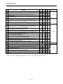
3.2 Component List
The operations of the following devices have been checked by Mitsubishi.
Name
Type
Remarks
PCI bus loading type, 2 channels/board
®
®
• The 64-bit edition of Windows 7/Windows 8 is not supported.
®
• The 32-bit/64-bit edition of Windows 8.1 is not supported.
• PCI bus built-in type.
SSC interface board
A10BD-PCF
®
®
®
• Up to 4 boards on one Windows XP/Windows Vista/Windows
®
7/Windows 8 operating PC
(Can be connected to up to 8 motion controllers)
PCMCIA type II, 1 channel/card
®
®
• The 64-bit edition of Windows 7/Windows 8 is not supported.
SSC interface card
A30CD-PCF
®
• The 32-bit/64-bit edition of Windows 8.1 is not supported.
• Up to 1 card on one personal computer.
Q170BDCBL3M
For A10BD-PCF
3m (9.84ft.)
Q170BDCBL5M
For A10BD-PCF
5m (16.40ft.)
Communication cable
Q170BDCBL10M
For A10BD-PCF 10m (32.81ft.)
(Note-1)
Q170CDCBL3M
For A30CD-PCF
3m (9.84ft.)
Q170CDCBL5M
For A30CD-PCF
5m (16.40ft.)
Q170CDCBL10M
For A30CD-PCF 10m (32.81ft.)
RS-232 cable
QC30R2
Mitsubishi Electric Corporation
(Note-1):Max. overall communication cable extension distance 30m.
The following shows the specifications of Ethernet cable.
Part name
Ethernet cable
Connection type
Ethernet
standard
Cable type
10BASE-T
Connection with HUB
Straight cable
Direct connection
Crossover cable
100BASE-TX
(Note-1)
10BASE-T
100BASE-TX
(Note-1): The following shows the selection criterion of cable.
• Category: 5 or higher.
• Diameter of lead: AWG26 or higher.
• Shield: Copper braid shield and drain wire.
Copper braid shield and aluminum layered type shield.
38
Model name
Compliant with Ethernet standards,
category 5 or higher.
• Shielded twisted pair cable (STP cable)
4. SETTING THE SSC INTERFACE BOARD
4. SETTING THE SSC INTERFACE BOARD
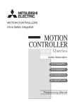
4.1 Setting the A10BD-PCF Interface Board
This section explains the switch setting of the A10BD-PCF interface board.
®
®
Note: The 64-bit edition of Windows 7/Windows 8 is not support.
®
The 32-bit/64-bit edition of Windows 8.1 is not support.
LED
SW1
SW1
MODE
BDID2
BDID1
BDID0
LED2
SW2
RESET
LED1
SW2
1 2 3 4
ON
CON1port
ON
1 2 3 4
CON2port
(1) Board ID setting switch (SW1)
When there are two or more PCI type A10BD-PCF's, set the ID numbers to
identify the respective A10BD-PCF's.
SW1
1
2
ON
1 2 3 4
3
4
Definition
Board ID bit 0
(BDID0)
Board ID bit 1
(BDID1)
Board ID bit 2
(BDID2)
Controller setting
(MODE)
Default
Remarks
OFF
OFF
Set the ID number.
For details, refer to the following
Table 4.1.
OFF
ON
Always set to ON.
1) Board ID bit choices 0 to 2 (SW1-1 to 3) and ID numbers
Table 4.1
ID Numbers
Switch Numbers
1
2
3
BDID0
BDID1
BDID2
OFF
OFF
OFF
ON
OFF
OFF
OFF
ON
OFF
ON
ON
OFF
Board ID
0
1
2
3
(2) Reset switch (SW2)
Turn on the reset switch (SW2) to reset the A10BD-PCF.
Do not press the reset switch during communication since doing so will shut off
communication.
If normal communication cannot be made, press the reset switch to reset the
A10BD-PCF and then start communication.
41
4. SETTING THE SSC INTERFACE BOARD
(3) LED display
Indicates the status of the A10BD-PCF.
When the A10BD-PCF is normal: LED Flickers
When the A10BD-PCF is abnormal: LED remains constant On or Off
LED1 For CON1 port
LED2 For CON2 port
(4) Allotment between Board IDs and SSCNET CH No.
Board ID
0
1
2
3
CON1 port
CH.0
CH.2
CH.4
CH.6
42
CON2 port
CH.1
CH.3
CH.5
CH.7
5. COMMUNICATION DRIVER INSTALLATION PROCEDURE
5. COMMUNICATION DRIVER INSTALLATION PROCEDURE
5.1 USB Driver Installation Procedure
®
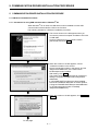
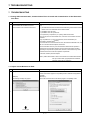
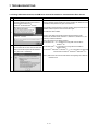
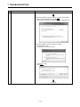
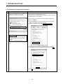
5.1.1 Precautions for using USB communication in Windows XP
®
When Windows XP is used, the USB driver must be installed to make USB
communication with the Motion CPU for the first time.
The following indicates a USB driver installation procedure.
1) The screen shown on the left appears when you
connect the personal computer and Motion CPU with
a USB cable.
Choose "Install from a list or specific location
[Advanced]" and click Next >.
2) When the screen on the left appears, choose
"Include this location in the search".
Check "Include this location in the search" and set
"Easysocket\USBdrivers" of the folder where
MT Developer2 was installed.
After setting, click Next >.
The screen shown on the left shows an example of
setting C:\Program Files\MELSOFT\Easysocket\
USBdrivers.
If volume MELSOFT products have been installed,
browse the installation destination of the first product.
("\Program Files\MELSOFT\Easysocket\USBDrivers"
or "\[Folder where this product is installed]
\Easysocket\USBDrivers")
3) When the screen on the left appears, click Continue
Anyway.
To next page
51
5. COMMUNICATION DRIVER INSTALLATION PROCEDURE
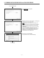
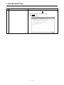
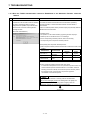
From preceding page
4) The screen on the left appears to indicate
completion of installation.
Click Finish to terminate installation.
52
5. COMMUNICATION DRIVER INSTALLATION PROCEDURE
®
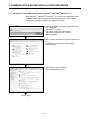
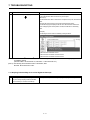
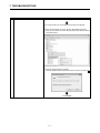
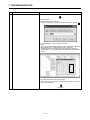
5.1.2 Precautions for using USB communication in Windows Vista
®
When Windows Vista is used, the USB driver must be installed to make USB
communication with the Motion CPU for the first time.
The following indicates a USB driver installation procedure.
1) The screen shown on the left appears when you
connect the personal computer and Motion CPU
with a USB cable.
Click [Locate and install driver software
(recommended)].
2) The screen on the left appears.
Click [Don’t search online].
3) The screen on the left appears.
Click [Browse my computer for driver software
(advanced)].
To next page
53
5. COMMUNICATION DRIVER INSTALLATION PROCEDURE
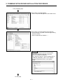
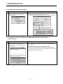
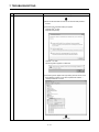
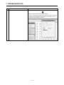
From preceding page
4) The screen on the left appears.
Click Browse….
5) When the screen on the left appears, set "Easysocket\USBdrivers" of the folder where
MT Developer2 was installed. After setting, click
Next.
The screen shown on the left shows an example of
setting C:\Program Files\MELSOFT\Easysocket\
USBdrivers.
If volume MELSOFT products have been installed,
browse the installation destination of the first
product. ("\Program Files\MELSOFT\Easysocket\
USBDrivers " or "\[Folder where this product is
installed]\Easysocket\USBDrivers")
6) The screen on the left appears.
Click [Install this driver software anyway].
To next page
54
5. COMMUNICATION DRIVER INSTALLATION PROCEDURE
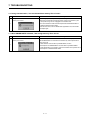
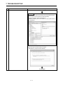
From preceding page
7) The screen on the left appears and the driver
installation starts.
8) The screen on the left appears to indicate
completion of installation.
Click Close to terminate installation.
55
5. COMMUNICATION DRIVER INSTALLATION PROCEDURE
®
®
®
5.1.3 Precautions for using USB communication in Windows 7/Windows 8/Windows 8.1
®
®
®
When Windows 7/Windows 8/Windows 8.1 is used, the USB driver must be
installed to make USB communication with the Motion CPU for the first time.
The following indicates a USB driver installation procedure.
®
<Windows 7 is used >
1) Connect the personal computer and Motion CPU
with a USB cable.
®
<Windows 7 is used >
The screen shown on the left appears.
®
®
<Windows 8/Windows 8.1 is used >
Nothing appears.
2) Select "System and Security" from the Control Panel.
To display the Control Panel, select [Start] [Control Panel].
3) The screen on the left appears.
Select "Administrative Tools".
To next page
56
5. COMMUNICATION DRIVER INSTALLATION PROCEDURE
From preceding page
4) The screen on the left appears.
Select "Computer Management" and double-click it.
5) The screen on the left appears when selecting
Device Manager in System Tools and right-clicking
"Unknown device".
Select "Update Driver Software…".
Remarks
If multiple "Unknown devices" exist therefore
cannot be specified, right-click "Unknown
device" and select "Properties".
The "Unknown device", whose "Hardware ID" is
"USB\VID_06D3&PID_1800" on the "Details"
tab of the properties screen, is the update
target.
To next page
57
5. COMMUNICATION DRIVER INSTALLATION PROCEDURE
From preceding page
6) The screen on the left appears.
Click [Browse my computer for driver software].
7) The screen on the left appears.
Set "Easysocket\USBDrivers" of the folder where
MT Developer2 was installed and then click Next.
The left screen is an example when C:\Program
Files\MELSOFT\Easysocket\USBDrivers is
specified.
If multiple MELSOFT products have been installed,
specify the installation location of the first installed
product.
For 64-bit edition: C:\Program Files (x86)\MELSOFT\
Easysocket\USBDrivers
8) The screen on the left appears.
Click Install.
9) The screen on the left appears and the driver
installation starts.
To next page
58
5. COMMUNICATION DRIVER INSTALLATION PROCEDURE
From preceding page
10) The screen on the left appears.
Click Close.
11) "MITSUBISHI Easysocket Driver" is registered
under "Universal Serial Bus controllers".
This completes driver installation.
59
5. COMMUNICATION DRIVER INSTALLATION PROCEDURE
5.2 Updating the USB Driver
®
®
®
®
In Windows Vista , Windows 7, Windows 8, Windows 8.1, if updating
MELSOFT to be compatible after installing an incompatible MELSOFT, updating
the USB driver is required.
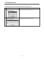
(1) Procedure for updating the USB driver for programmable controller connection
(a) Checking method
Start the Device Manager while the personal computer is connected to the
motion CPU with USB, right-click "MITSUBISHI Easysocket Driver", and
select "Properties".
Update is necessary if the version shown in the "Driver" tab of the properties
screen is the following.
®
: "2.0.0.0" or earlier
• Windows Vista is used
®
: "3.0.0.0" or earlier
• Windows 7 is used
®
®
: "4.0.0.0" or earlier
• Windows 8/Windows 8.1 is used
5 10
5. COMMUNICATION DRIVER INSTALLATION PROCEDURE
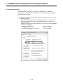
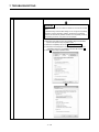
(b) Procedure for update
1) The screen on the left appears when the personal
computer and the motion CPU are connected with a
USB cable.
2) Start the Windows Device Manager, right-click
"MITSUBISHI Easysocket Driver" as shown on the
left, and select "Uninstall".
3) The warning dialog box as shown on the left appears.
Check the "Delete the driver software for this device"
check box, and click OK.
®
<Windows Vista is used>
4) Disconnect the USB cable and reconnect it to the
same USB port after 5 seconds.
®
<Windows Vista is used>
The screen on the left appears for a while.
Click [Ask me again later].
®
<Windows 7 is used >
®
<Windows 7 is used>
The screen on the left appears for a while.
To next page
5 11
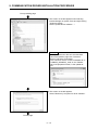
5. COMMUNICATION DRIVER INSTALLATION PROCEDURE
From preceding page
5) The screen on the left appears when selecting
Device Manager in System Tools and right-clicking
"Unknown device".
Select "Update Driver Software…".
Remarks
If multiple "Unknown devices" exist therefore
cannot be specified, right-click "Unknown
device" and select "Properties".
The "Unknown device", whose "Hardware ID" is
"USB\VID_06D3&PID_1800" on the "Details"
tab of the properties screen, is the update target.
6) The screen on the left appears.
Select "Browse my computer for driver software".
To next page
5 12
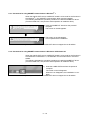
5. COMMUNICATION DRIVER INSTALLATION PROCEDURE
From preceding page
7) The screen on the left appears.
Set "Easysocket\USBDrivers" of the folder where
MT Developer2 was installed and then click Next.
The left screen is an example when C:\Program Files\
MELSOFT\Easysocket\USBDrivers is set.
If multiple MELSOFT products have been installed,
refer to the installation location of the first installed
product.
®
8) The screen on the left appears.
®
<Windows Vista is used>
Click [Install this driver software anyway].
<Windows Vista is used>
®
®
®
< Windows 7/Windows 8/Windows 8.1 is
used >
®
®
®
< Windows 7/Windows 8/Windows 8.1 is used>
Click Install.
9) The screen on the left appears.
Click Close.
The update is complete.
5 13
5. COMMUNICATION DRIVER INSTALLATION PROCEDURE
5.3 SSCNET Driver Installation Procedure
5.3.1 Precautions for using SSCNET communication in Windows® XP
When the A30CD-PCF card or A10BD-PCF board is to be used for the first time in
the Windows® XP, the SSCNET communication driver must be installed.
The following indicates the operation procedure to install the A30CD-PCF driver.
(For the A10BD-PCF, also perform similar operation to install the driver.)
1) Insert the A30CD-PCF card into the personal
computer.
The screen on the left will soon appear.
Choose "Install the software automatically
[Recommended]" and click Next >.
2) The screen on the left appears.
Click Continue Anyway.
3) The screen on the left appears.
Click Finish.
This completes driver installation.
5 14
5. COMMUNICATION DRIVER INSTALLATION PROCEDURE
5.3.2 Precautions for using SSCNET communication in Windows Vista®
When the A30CD-PCF card or A10BD-PCF board is to be used for the first time in
the Windows Vista®, the SSCNET communication driver must be installed.
The following indicates the operation procedure to install the A10BD-PCF driver.
(For the A30CD-PCF, also perform similar operation to install the driver.)
1) Insert the A10BD-PCF board into the personal
computer.
The screen on the left appears.
Click "Locate and install driver software
(recommended)".
2) The screen on the left appears.
Click "Install this driver software anyway".
3) The screen on the left appears.
The "SSCNET PCI Board (A10BD-PCF)" name
window appears on the indicator.
This completes driver installation.
5 15
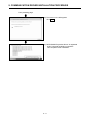
5.3.3 Precautions for using SSCNET communication in Windows® 7
When the A30CD-PCF card or A10BD-PCF board is to be used for the first time in
the Windows® 7, the SSCNET communication driver must be installed.
The following indicates the operation procedure to install the A30BD-PCF driver.
(For the A10CD-PCF, also perform similar operation to install the driver.)
1) Insert the A30BD-PCF board into the personal
computer.
The screen on the left appears.
2) The screen on the left appears.
This completes driver installation.
(Note-1): A30CD-PCF and A10BD-PCF does not support the 64-bit edition.
5.3.4 Precautions for using SSCNET communication in Windows® 8/ Windows® 8.1
When the A30CD-PCF card or A10BD-PCF board is to be used for the first time in
the Windows® 8/ Windows® 8.1, the SSCNET communication driver must be installed.
The following indicates the operation procedure to install the A30BD-PCF driver.
(For the A10CD-PCF, also perform similar operation to install the driver.)
1) Insert the A30BD-PCF board into the personal
computer.
The screen on the left appears.
When the icon disappears, the installation is complete.
(Note-1): A30CD-PCF and A10BD-PCF does not support the 64-bit edition.
5 16
6. PRECAUTION
6. PRECAUTION
6.1 Uninstallation of SW6RN-SNETP or SW3RN-SNETP
Do not uninstall "SSCNET Communication Driver" when uninstalling the
SW6RN-SNETP (Ver.00B or later) or SW3RN-SNETP (Ver.00G or later) in a
personal computer where multiple MT Developer2 and SW6RNC-GSVE
(MT Developer) or SW3RNC-GSVE are installed.
If the SSCNET communication driver is uninstalled, reinstall MT Developer2.
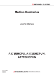
6.2 Finding Ethernet Built-in Type CPU on the Network
When "Find Ethernet Built-in Type CPU on the
Network" is executed at the CPU side I/F CPU module
detail setting in the transfer setup, the "Windows
Security Alert" dialog box may appear.
If this dialog box appears, select "Unblock".
When selecting "Block", operate as follows.
Mark the checkbox of "MT Developer2" in the
"Programs and Services" list on the "exceptions" tag of
Windows Firewall.
The image of the dialog box differs depending on Windows you use.
For details of the Windows Firewall settings, refer to Windows Help.
61
7. TROUBLESHOOTING
7. TROUBLESHOOTING
7.1 During USB Communication, Communication Error Occurred and Communication Is Not Recovered
from Error
No.
Phenomenon
Cause and remedy
A communication error occurred during USB
Any of operations 1) to 3) was performed during USB communication with the Motion
communication with the Motion CPU, and
CPU.
communication is not recovered from the error.
1) The USB cable was disconnected and connected during communication with the
Motion CPU or connected after communication started.
2) The Motion CPU was reset.
3) The Motion CPU was cycled on/off.
Do not perform any of operations 1) to 3) during USB communication.
Doing so may cause a communication error, from which communication cannot be
recovered.
If any of operations of 1) to 3) is to be performed, it is recommended to put
MT Works2 in an offline status(Note-1).
1
If communication is not recovered from the error, disconnect the USB cable once, and
after 5 or more seconds have elapsed, reconnect it.
(The communication error may occur at the first time after the above operation is
performed, but communication will return to normal at the second time and later.)
Depending on the personal computer model, however, communication may not be
recovered from the error if the above operation is performed.
In that case, reset the personal computer.
(Note-1): Offline status: Status in which communication is not made with the Motion
CPU (In an online status, program/parameter read/write,
monitoring, test or like is in execution.)
7.2 Project Cannot Be Saved or Read
No.
Phenomenon
A project cannot be saved or read.
Cause and remedy
<Cause 1)>
The item "Execute this program in compatibility mode" is selected in the application
properties.
(Example)
<Remedy 1)>
The following message may appear.
Remove the check mark from "Execute this program in compatibility mode".
1
To next page
71
7. TROUBLESHOOTING
No.
Phenomenon
Cause and remedy
From preceding page
<Cause 2)>
A part of the Microsoft .NET Framework may be corrupted.
<Remedy 2)>
Uninstall the Microsoft .NET Framework from the personal computer, download the
latest
Microsoft .NET Framework from the web site of Microsoft and install it.
Uninstall all the programs displayed with the name "Microsoft .NET Framework".
When multiple programs are required to uninstall, uninstall them in descending
order.
(Example)
The following shows the order of uninstalling of the figure below.
1) Microsoft .NET Framework 3.5 SP1
2) Microsoft .NET Framework 3.0 Service Pack 2
3) Microsoft .NET Framework 2.0 Service Pack 2
®
®
(Note-1): For Windows Vista and Windows 7, .Net Framework may not be displayed in "Uninstall or change a program" since it
is installed by default.
®
®
(Windows Vista : .Net Framework 3.0, Windows 7: .Net Framework 3.51)
(Note-2): The following shows the latest version in November, 2009.
Microsoft .NET Framework 3.5 SP1
7.3 Sampling Omission May Occur on the Digital Oscilloscope
No.
Phenomenon
On the digital oscilloscope, a sampling omission
1
Cause and remedy
If other operation is performed during sampling, a sampling failure may occur.
may occur during sampling of data by SSCNET
communication (PC real-time read method).
72
7. TROUBLESHOOTING
7.4 Digital Oscilloscope Cannot Be Started
No.
Phenomenon
Cause and remedy
®
When the digital oscilloscope is started, the following Check whether DirectX can be operated by the DirectX Diagnostic Tool.
®
message appears and the digital oscilloscope
Choose the [Display] tab in the DirectX Diagnostic Tool.
cannot be started.
Check whether "DirectDraw Acceleration" of the "DirectX Features" is "Enabled".
1
7.5 The SSCNET Communication Manager of SW6RN-SNETP Displays "Shared Memory
Connection Error"
No.
Phenomenon
Cause and remedy
The SSCNET communication manager of
With MT Developer2 and SW6RN-SNETP started simultaneously, operation to
SW6RN-SNETP displays "Connected To The
start SW6RN-SNETP or to execute communication may cause a phenomenon
Shared Memory Error" and SW6RN-SNETP is not
shown on the left.
started properly.
To start SSCNET communication by SW6RN-SNETP, exit from
MT Developer2 and SW6RN-SNETP once and restart only SW6RN-SNETP.
To execute SSCNET communication, make communication with only either one of
MT Developer2 or SW6RN-SNETP started.
1
If SSCNET communication is started in this status,
communication error "51" occurs.
73
7. TROUBLESHOOTING
7.6 During Communication, "Can not allocate Share memory" Error Occurs
No.
Phenomenon
Cause and remedy
During communication, "Can not allocate Share
The following operations may cause the phenomenon given on the left.
memory" error occurs.
• When the communication is forcibly shut down, during communication, by the
CPU power turning off or an unplugged communication cable.
• The communication is made at MT Developer2 side while SW3RN-SNETP is
1
started (including the online status).
When this error occurs, exit from all MELSOFT applications once, and start MT
Developer2 again.
7.7 When SW3RN-SNETP Is Started, "Not enough memory" Error Occurs
No.
Phenomenon
Cause and remedy
When SW3RN-SNETP is started, "Not enough
With MT Developer2 and SW3RN-SNETP started simultaneously, operation to
memory" error occurs.
start SW3RN-SNETP or to execute communication may cause a phenomenon
shown on the left.
1
To start SSCNET communication by SW3RN-SNETP, exit from
MT Developer2 and SW6RN-SNETP once and restart only SW3RN-SNETP.
To execute SSCNET communication, make communication with only either one of
MT Developer2 or SW3RN-SNETP started.
74
7. TROUBLESHOOTING
7.8 During USB Communication, the USB Driver Cannot Be Installed or Communication Error Occurs
No.
Phenomenon
Cause and remedy
The following error occurs and the USB driver
When USB communication is performed in normal mode with a Motion CPU on
cannot be installed when USB communication is
which the Operating system software has not been installed, the USB driver cannot
performed with the Motion CPU.
®
®
<Windows XP/Windows Vista is used>
be installed, and the phenomenon given on the left occurs.
If the Operating system software has not been installed, change the Motion CPU to
installation mode, and perform USB communication again.
The USB driver will be installed.
1
®
<Windows 7 is used>
However, when USB communication is performed for the first time under
®
®
®
®
®
Windows XP, Windows Vista , Windows 7, Windows 8, Windows 8.1, it is
necessary to install the USB driver.
Refer to the following for the setting procedure.
®
• For Windows XP : "5.1.1 Precautions for using USB communication in
®
The following communication error occurs and
®
• For Windows Vista : "5.1.2 Precautions for using USB communication in
®
communication with the CPU cannot be done when
USB communication is performed with the Motion
Windows XP"
®
Windows Vista "
®
®
• For Windows 7/Windows 8/ Windows 8 .1 : "5.1.3 Precautions for using USB
®
CPU. (Error Code = 0x1808502)
®
®
communication in Windows 7/Windows 8/Windows 8.1"
(Note-1): Refer to the user manual of each Motion CPU regarding how to deal with
2
the Motion CPU.
75
7. TROUBLESHOOTING
7.9 USB communication fails with Windows Vista®/Windows® 7/Windows® 8/Windows® 8.1
No.
Phenomenon
Cause and remedy
®
USB communication fails with Windows Vista /
Check the version of the installed USB communication driver.
Windows 7/Windows 8/Windows 8.1
<Occurrence cause 1)>
®
®
®
®
®
®
®
The occurs when installing Windows Vista /Windows 7/Windows 8/Windows
8.1 incompatible MELSOFT and connecting to the Motion CPU with USB before
®
®
®
®
installing Windows Vista /Windows 7/Windows 8/Windows 8.1 compatible
MELSOFT.
<Occurrence cause 2)>
The situation may occur when installing MELSOFT and connecting the personal
computer to the Motion CPU with USB on the personal computer where multiple
Windows are installed.
(Example)
®
Drive C: Windows XP (MELSOFT installed)
®
®
®
®
Drive D: Windows Vista /Windows 7/Windows 8/Windows 8.1
The communication error occurs when MELSOFT is installed on the Windows
®
®
®
®
Vista /Windows 7/Windows 8/Windows 8.1 environment of drive D and the
USB communication is tried.
®
In this case, the driver for Windows XP of drive C may have been used.
<Checking method>
Start the Windows Device Manager while the personal computer is connected to
the Motion CPU with USB, right-click "MITSUBISHI Easysocket Driver", and select
[Properties].
If "Driver Version" on the "Driver" tab of the properties screen is as followings, the
setting applies to the occurrence cause and a communication failure occurs.
®
"2.0.0.0 or earlier when Windows Vista is used",
1
®
"3.0.0.0 or earlier when Windows 7 is used"
®
®
"4.0.0.0 or earlier when Windows 8/ Windows 8.1 is used"
®
®
®
®
Update the USB driver with Windows Vista /Windows 7/Windows 8/Windows
8.1-compatible MELSOFT installed following the recovery method shown below.
To next page
76
7. TROUBLESHOOTING
No.
Phenomenon
Cause and remedy
From preceding page
(1) Connect the Motion CPU and the personal computer with a USB cable.
(2) Start the Device Manager of the OS, right-click "MITSUBISHI Easysocket
Driver" as shown below, and choose "Uninstall".Update the USB driver referring
to the following items.
(3) The following warning dialog box appears.
Check the "Delete the driver software for this device" check box, and select OK.
To next page
77
7. TROUBLESHOOTING
No.
Phenomenon
Cause and remedy
From preceding page
(4) Disconnect the USB cable and reconnect it to the same USB port after 5
seconds.
(5) The following OS confirmation dialog box appears.
®
<Windows Vista is used>
Click [Ask me again later].
®
<Windows 7 is used>
The following balloon appears for a little while.
(6) The following screen appears when right-clicking "Unknown device" in the
Device Manager of System Tools. Select "Update Driver Software…".
®
< Example: Windows 7 is used>
To next page
78
7. TROUBLESHOOTING
No.
Phenomenon
Cause and remedy
From preceding page
Remarks
If multiple "unknown devices" exist therefore cannot be specified, right-click
"Unknown device" as shown below and select [Properties].
The "Unknown device", whose "Hardware Ids" is
"USB¥VID_06D3&PID_1800" on the "Details" tab of the properties screen, is
the update target.
(7) The following OS confirmation dialog box appears.
Click [Browse my computer for driver software].
To next page
79
7. TROUBLESHOOTING
No.
Phenomenon
Cause and remedy
From preceding page
(8) The following Windows confirmation dialog box appears. Set the installed
location "Easysocket¥USBDrivers" and click Next.
Default is set as " C:¥Program Files¥MELSOFT¥Easysocket¥USBDrivers".
(9) The following Windows confirmation dialog box appears.
®
<Windows Vista is used>
Click [Install this driver software anyway].
®
<Windows 7 is used>
Click Install.
To next page
7 10
7. TROUBLESHOOTING
No.
Phenomenon
Cause and remedy
From preceding page
(10) The following OS confirmation dialog box appears.
Click Close.
The update is complete.
7 11
7. TROUBLESHOOTING
7.10 MR Configurator Fails to Be Started from MT Developer2 (Linkage Function)
No.
Phenomenon
Cause and remedy
When MR Configurator is started from
An MR Configuration version which does not support MT Developer2 is installed.
MT Developer2, the following error occurs and the
Update the version of MR Configurator to Ver.C1 or later.
starting fails. (linkage function)
1
When MR Configurator is started from
MT Developer2, the following error occurs and the
starting fails. (linkage function)
MR Configurator version which does not support Q170M is installed.
Update the version of MR Configurator to Ver.C2 or later.
2
7 12
7. TROUBLESHOOTING
(Note-1)
7.11 Operation when Using a Program Data, Created with the Japanese Edition
in the English
(Note-2)
Edition
No.
Phenomenon
Cause and remedy
The Motion SFC Program Name Is Not Displayed
This situation occurs when Japanese characters are used.
Correctly.
Change the Japanese characters to the ASCII characters with the Japanese edition
before opening the project with the English edition.
The project may also be opened by deleting the garbled characters and entering
characters in the English edition.
1
The motion SFC chart (symbols) comments, or
comments in the F/G program are not displayed
correctly.
2
(Note-1): MT Developer (SW6RNC-GSVE), MT Developer2
(Note-2): MT Developer2
7 13
7. TROUBLESHOOTING
7.12 When Installation does not Complete or Warning Dialog Boxes are Displayed
No.
Phenomenon
Cause and remedy
®
®
®
The following warning dialog boxes may appear on
The warning dialog boxes appear when Windows Vista /Windows 7/Windows
a Windows Vista /Windows 7/Windows
8/Windows 8.1 incompatible driver software is installed to a Windows
8/Windows 8.1-based personal computer.
Vista /Windows 7/Windows 8/Windows 8.1 compatible personal computer in
®
®
®
®
®
®
®
®
®
the either of the following conditions.
<Occurrence condition 1)>
®
®
®
®
When installing Windows Vista /Windows 7/Windows 8/Windows 8.1
incompatible MELSOFT.
<Occurrence condition 2)>
When "Reinstall using recommended settings" is selected on the "Program
Compatibility Assistant" screen by mistake after installing MELSOFT.
CAUTION
The warning dialog boxes shown above may
be hidden behind the screen of MELSOFT
installer.
Press Alt + Tab to bring them to front.
1
<Corrective action>
Press OK on each warning dialog box and complete the installation.
Perform either of the following corrective actions corresponding to the occurrence
condition.
Corrective action for occurrence condition 1):
®
®
®
®
Install Windows Vista /Windows 7/Windows 8/Windows 8.1
-compatible software updated version following the procedures below.
®
• Windows Vista : "5.1.2 Precautions for using USB communication in
®
®
Windows Vista "
®
®
• Windows 7/Windows 8/Windows 8.1 : "5.1.3 Precautions for using USB
®
®
®
communication in Windows 7/Windows 8/Windows 8.1"
Corrective action for occurrence condition 2):
Reinstall the MELSOFT product.
Ensure to select "This program installed correctly" on the "Program
Compatibility Assistant" screen.
Corrective action is described below.
To next page
7 14
7. TROUBLESHOOTING
No.
Phenomenon
Cause and remedy
From preceding page
CAUTION
Note the following when the installer is started from the internal hard disk
drive.
If "Reinstall using recommended settings" on the "Program Compatibility
Assistant" screen is selected by mistake, 'Windows XP compatibility
mode' is set automatically. Disable "Windows XP compatibility mode" by
the following procedure, and perform the reinstallation.
1). Right-click on the setup.exe icon of the installation target in the Windows
explorer, and open the "setup Properties" screen.
2). Select the "Compatibility" tab and click Show settings for all users.
3). Uncheck the "Run this program in compatibility mode for: "check box of
compatibility mode in the "Compatibility for all users" tab and click OK.
4). Click OK on the "setup Properties" screen.
7 15
7. TROUBLESHOOTING
7.13 A Dialog Box is Displayed after an Installer
No.
Phenomenon
Cause and remedy
The following warning dialog boxes may appear on
®
®
®
<Corrective action>
a Windows Vista /Windows 7/Windows
Ensure to select "This program installed correctly".
8/Windows 8.1-based personal computer.
If "Reinstall using recommended settings" is selected by mistake, "Windows XP
®
compatibility mode" is set automatically.
Disable "Windows XP compatibility mode" by the following procedure, and
perform the reinstallation.
1). Right-click on the setup.exe icon of the installation target in the Windows
explorer, and open the "setup Properties" screen.
2). Select the "Compatibility" tab and click Show settings for all users.
CAUTION
The warning dialog boxes shown above may
be hidden behind the screen of MELSOFT
installer.
Press Alt + Tab to bring them to front.
1
3). Uncheck the "Run this program in compatibility mode for: "check box of
compatibility mode in the "Compatibility for all users" tab and click OK.
4). Click OK on the "setup Properties" screen.
7 16
7. TROUBLESHOOTING
7.14 When the TCP/IP Communication cannot be Established or the Simulation Function cannot be
Started
No.
Phenomenon
Cause and remedy
As the TCP/IP communication with the Motion CPU The TCP/IP communication function and simulation function of
is established or the simulation function is started on MT Works2 are based on the standard TCP/IP communication provided by
MT Works2, the following dialog box may be
Microsoft Corporation. In cases where these functions cannot be started, a
displayed and the operation may not be able to be
communication
performed even if corrective actions against the
function of a software product made by another company may adversely affect the
message are taken.
standard TCP/IP communication.
(Error Code <ES:01808201>)
<Corrective action>
This problem can be workarounded by upgrading another company's
software product to the latest version or uninstalling it.
For the corresponding software products, refer to the following
"Corresponding other companies’ software products".
<Corresponding other companies' software products>
(1) Other companies' software products that have been confirmed as causes of this
problem
Manufacturer
WILLCOM, Inc.
1
Digital Arts Inc.
SOURCENEXT
CORPORATION
Sprint Inc.
Product name
Confirmed by
(version)
Corrective
action
3.1.2
Upgrade
4.01.08
Upgrade
9.5.0072
Uninstall
2.25.0046
Uninstall
Venturi Client for
AIR-EDGE
i-FILTER
Virus Security
ZERO
Sprint SmartView
(2) Other companies' software products other than above
In cases where this problem occurs on a personal computer on which any
of these software products mentioned above is not installed, follow the
following procedure to identify which software product adversely affects
the standard TCP/IP communication, and perform upgrade or
uninstallation of the software product.
POINT
Registry values are referred in <Checking method> described below.
Be sure not to edit registry values when referring them. The registry is an
important component for the operating system. If registry values are
erroneously changed, the computer may not work properly.
To next page
7 17
7. TROUBLESHOOTING
No.
Phenomenon
Cause and remedy
From preceding page
<Checking method>
1) Start the Registry Editor on Windows.
Click [Run] via [Start], type "regedit" on the displayed dialog box, and click OK.
2) In the Registry Editor, perform the following operation.
Under
"HKEY_LOCAL_MACHINE¥SYSTEM¥CurrentControlSet¥Services¥WinSock2
¥Parameters¥Protocol_Catalog9¥Catalog_Entries", double-click
"PackedCatalogItem" in sequentially-numbered registry keys starting from
"000000000001", such as "000000000001", "000000000002", "000000000003",
and so on.
If a displayed dll file name is other than "mswsock.dll" and "rsvpsp.dll", the dll file
likely affects the standard TCP/IP communication.
When more than one sequentially-numbered registry key exists, check a dll file
name in every registry key.
To next page
7 18
7. TROUBLESHOOTING
No.
Phenomenon
Cause and remedy
From preceding page
3) Identify a software product made by another company.
Identify the product name by opening the properties of the dll file checked in the
above step 2 and confirming its "Product Name" and "Description" etc. or by
searching for the dll file name on the web.
7 19
7. TROUBLESHOOTING
7.15 Start the Unexpected Auxiliary Screen in MT Developer2
No.
Phenomenon
®
In Windows8.1 (Simplified Chinese), unexpected
auxiliary screen might be started on MT
Cause and remedy
<Corrective action>
OFF the Chinese (English ON) in IME language preferences.
Developer2 setting screen when executing
numerical entry.
(Example)
Servo Data Screen
Fixed Parameter Item
1
7 20
APPENDICES
APPENDIX 1 Added Functions
The following table shows the functions that are added to MT Developer2.
No.
Description
SV13 SV22 SV43 SV54
1
The help jump function by the F1 key is added.
2
The import multiple CPU parameter function is added.
3
The operability of the monitor function is improved.
4
The operability of the mechanical system program function is improved.
8
The safety observation function is supported.
(iQ Platform compatible motion controller with the safety observation function)
Q173DCPU/Q172DCPU /Q173HCPU/Q172HCPU/Q173CPU/Q172CPU is
supported.
The expression and input of decimal comma is supported.
(Note-1): Except for motion program of SV43/SV54.
®
®
Windows XP Service Pack 3 and Windows Vista Service Pack 1 are
supported.
9
The save function of current value history monitor is added.
10
The operability of the system setting function is improved.
11
The operability of the motion SFC program function is improved.
12
Q170MCPU is supported.
13
The servo programs CHGA-E/CHGA-C instructions and motion dedicated PLC
instruction D(P).CHGA can be displayed on the scroll monitor screen for the
Q173DCPU/Q172DCPU.
(Note-1): Q170MCPU is supported by Ver.1.05F.
14
The 0.4ms event task is supported for the Q173DCPU/Q172DCPU.
5
6
7
17
The MR-J3-B DD motor is supported for the Q173DCPU/Q172DCPU.
(Note-1): Q170MCPU is supported by Ver.1.05F.
The CPU built-in I/F (I/O signal (DI/DO)) function is supported for the
Q170MCPU.
The CPU built-in I/F (manual pulse generator/INC synchronous encoder)
function is supported for the Q170MCPU.
18
The mark detected function is supported for the Q170MCPU.
19
The MC protocol communication is supported for the Q170MCPU.
15
16
20
21
22
23
24
1.03D
1.05F
The advanced S-curve acceleration/deceleration function is supported for the
Q173DCPU/Q172DCPU/Q170MCPU.
(Note-1): Except for constant speed control of the servo program (CPSTART
instruction).
The message displayed when rewriting the data processing processor OS of
Q173HCPU/Q172HCPU/Q173CPU/Q172CPU, which supports the data
processing processor OS, is improved.
The CPU information screen is added.
When connecting CPU, you can start from the menu [Help] → [CPU Information].
The label input assist function is added for the Q173DCPU/Q172DCPU/
Q170MCPU projects.
Target: Motion SFC Program, Servo Program, Mechanical System Program
The cross reference function is added for the Q173DCPU/Q172DCPU/
Q170MCPU projects.
Target: Label Editor, Motion SFC Program, Servo Program, Mechanical System
Program
25
The find device function is added for the mechanical system program.
26
The label specification is enabled for the mechanical system program of the
Q173DCPU/Q172DCPU/Q170MCPU projects.
27
Copying between projects is enabled for the limit switch data.
28
Changing CPU type and diverting are enabled from Q173DCPU/Q172DCPU/
Q170MCPU projects to Q173HCPU/Q172HCPU/Q173CPU/Q172CPU projects.
1.06G
: Supported
APP 1
Supported
version
: Not supported
APPENDICES
No.
Description
SV13 SV22 SV43 SV54
29
The simulation function is added for the Q173DCPU/Q172DCPU.
30
Q173HCPU/Q172HCPU/Q173CPU/Q172CPU is supported.
31
32
33
34
The GOT transparent function via Ethernet module is supported for Q170MCPU.
(Note-1): PERIPHERAL I/F connector of Q170MCPU is not supported.
The GOT transparent function via Ethernet is supported for Q173DCPU/
Q172DCPU.
The advanced S-curve acceleration/deceleration function in the servo program
(constant speed control: CPSTART instruction) is supported for Q173DCPU/
Q172DCPU/Q170MCPU.
The Division setting function is added for the digital oscilloscope.
36
The writing to/reading from CPU function of the cam edit data is added for
Q173DCPU/Q172DCPU/Q170MCPU projects, and editing cam data in
MT Developer2 by the cam data read from the motion CPU is enabled.
The system label function in MELSOFT iQ Works is supported for the
Q173DCPU/Q172DCPU projects.
37
The parameter interaction function of MELSOFT iQ Works is supported.
38
MELSOFT iQ Works (Ver.1.05F) is supported.
39
The compress/unpack function of the project data is added.
40
The screen style and toolbar icon are changed.
35
42
The backup and load of the motion error history with the CPU backup function
are enabled for the Q173DCPU/Q172DCPU/Q170MCPU.
The motion controller dedicated device help is added for the
Q173DCPU/Q172DCPU/Q170MCPU.
43
Unpacking by dragging and dropping project compressed files is supported.
44
The interaction function with MR Configurator2 is supported.
45
Windows Vista Service Pack 2 is supported.
41
The organization of HELP contents was modified as to improve its visualization.
47
The setup guidance is added to the start menu.
48
Data for GX Works2 is added as a sample data of Q170MCPU.
49
The movement average is added to the operation setting of the device dump for
the digital oscilloscope.
50
The assistant function is added for the digital oscilloscope.
58
The motion controller dedicated device help is added for the Q173HCPU/
Q172HCPU/Q173CPU/Q172CPU.
The motion controller dedicated device help is added for the Q173DCPU/
Q172DCPU.
(Note-1): This is added in Ver.1.09K for Q173DCPU/Q172DCPU/Q170MCPU
SV13/SV22.
The changing of the system setting (except automatic refresh setting) and servo
data setting is supported for changing CPU type and diverting from Q173DCPU/
Q172DCPU/Q170MCPU projects to Q173HCPU/Q172HCPU projects.
The backup and load of the motion error history with the CPU backup function
are enabled for the Q173DCPU/Q172DCPU.
(Note-1): This is added in Ver.1.09K for the Q173DCPU/Q172DCPU/Q170MCPU
SV13/SV22.
The DFLT instruction and SFLT instruction are added to the operation control
program and transition program of the motion SFC program for the Q173DCPU/
Q172DCPU/Q170MCPU.
Labels can be used at the motion SFC parameter execution flag for the
Q173DCPU/Q172DCPU/Q170MCPU.
The count type home position return method using the external signals of
amplifier is enabled for the Q173DCPU/Q172DCPU.
The scale home position signal detection type is added to the home position
return method for the Q173DCPU/Q172DCPU/Q170MCPU.
59
The operability of the servo data setting function is improved.
60
Connection with the AC servo driver (VC II Series) for DD motor made by Nikki
Denso Co., Ltd. is supported for the Q173DCPU/Q172DCPU/Q170MCPU.
52
53
54
55
56
57
1.09K
®
46
51
Supported
version
1.15R
: Supported
APP 2
: Not supported
APPENDICES
No.
61
Description
SV13 SV22 SV43 SV54
FR-A700 is supported for the Q173DCPU/Q172DCPU/Q170MCPU.
63
The GOT transparent function via CPU built-in PERIPHERAL I/F is supported for
the Q173DCPU-S1/Q172DCPU-S1/Q170MCPU.
The Ethernet transfer setting and MC protocol in the CPU built-in PERIPHERAL
I/F is supported for the Q173DCPU-S1/Q172DCPU-S1.
64
Connection with the vision system made by Cognex Corporation is supported.
65
Microsoft Windows 7 is supported.
62
®
74
75
Q173DSCPU and Q172DSCPU are supported.
76
The simulation function is added for the Q173DSCPU/Q172DSCPU.
77
The axis label function is added for the Q173DSCPU/Q172DSCPU.
78
The software security key function is added for the Q173DSCPU/Q172DSCPU.
79
The electronic gear setting function is added for the Q173DSCPU/Q172DSCPU/
Q173DCPU/Q172DCPU/Q170MCPU/Q173HCPU/Q172HCPU.
80
The project verification function is added.
81
The verification function with the motion CPU is improved.
82
The operability of the servo program editing is improved.
83
The operability of the project tree is improved.
84
The cross reference function can be used for all CPU projects.
The program control instructions (IF to ELSE to IEND, SELECT to CASE to
SEND, FOR to NEXT, BREAK) are added to the operation control program and
transition program of the motion SFC program for the
Q173DSCPU/Q172DSCPU/Q173DCPU/Q172DCPU/Q170MCPU.
The vision system dedicated function, MVOUT instruction, is added to the
operation control program and transition program of the motion SFC program for
the Q173DSCPU/Q172DSCPU/Q173DCPU/Q172DCPU/Q170MCPU.
67
68
69
70
71
72
73
85
86
87
1.17T
1.19V
1.39R
The operability of the device batch monitor is improved.
88
The operability of the device test is improved.
89
91
The watch function is added.
The operability of the execute step monitor and specified step monitor is
improved.
The single file format project is supported in addition to the conventional
workspace format project in the project opening/saving function.
92
The revision function is added.
93
The project batch conversion function is added.
90
1.15R
®
The real-time display function of Digital Oscilloscope is added for the
Q173DCPU/Q172DCPU/Q170MCPU.
Capacity calculation function of labels/structure data to be written in the memory
card is added for the Q173DCPU/Q172DCPU/Q170MCPU.
Device Comment function is added.
(Note-1): Device comment data cannot be written to the Motion CPU.
It is available only on project data.
Option to display all folders is added in the "Open Project" dialog box, which
enables to open projects not controlled in the workspace.
®
®
Microsoft Windows 7 (For 64-bit edition) is supported.
®
®
Microsoft Windows 7 Service Pack 1 is supported.
The GOT transparent function for connecting GOT and a personal computer by
the Ethernet is supported.
The multiple CPU high speed main base unit with 5 slot (Q35DB) is supported
for the Q173DCPU/Q172DCPU.
A project of the motion controller A series created in SW3RNC-GSVE can be
diverted to a project of the motion controller Q series.
Q170MCPU is supported.
(Note-1): SV13 and SV22 are already supported by Ver.1.05F.
66
Supported
version
: Supported
APP 3
: Not supported
APPENDICES
No.
94
95
96
97
98
Description
SV13 SV22 SV43 SV54
The operability of label editor in the Q173DSCPU/Q172DSCPU/Q173DCPU/
Q172DCPU/Q170MCPU was improved.
• Added sort function.
• Added undo/redo function.
• Added CSV file import/export function.
• Hold the structure member status when changing the label name which used
structure.
Added the function which batch-replaces program device No. to label name in
the Q173DSCPU/Q172DSCPU/Q173DCPU/Q172DCPU/Q170MCPU.
The operability of optional data monitor in the Q173DSCPU/Q172DSCPU/
Q173DCPU/Q172DCPU/Q170MCPU/ Q173HCPU/Q172HCPU was improved.
The target parameter converting function below is added when executing the
following operation for the Q173DSCPU/Q172DSCPU/Q173DCPU/Q172DCPU/
Q170MCPU/Q173HCPU/Q172HCPU.
• File diversion, CPU/OS type changing and basic setting (SSCNET setting)
changing
[Target parameter]
• Electronic gear (Number of pulses per revolution, travel value per revolution)
• Servo parameter (from MR-J2S-B to MR-J3-B, from MR-J2S-B to MR-J4-B, or
from MR-J3-B to MR-J4-B)
The monitor function is improved.
100
The advanced synchronous control method is supported for the
Q173DSCPU/Q172DSCPU.
101
MELSOFT iQ Works (Ver.1.43V) is supported.
103
The simulation function in the advanced synchronous control method is added
for the Q173DSCPU/Q172DSCPU.
The unused operation control programs and transition programs in Motion SFC
program can be displayed in project tree.
104
The operability of the mark detection function is improved.
105
While executing Motion SFC program monitor, cross reference can be executed.
107
The initial mode while executing Motion SFC program monitor was changed to
the specified step monitor mode.
The display can jump to the corresponding part from the verify result of cam in
advanced synchronous control method.
108
Q170MSCPU/Q170MSCPU-S1 is supported.
106
109
110
111
112
113
114
115
1.42U
1.47Z
1.52E
Universal model high speed type (Q03UDVCPU, Q04UDVCPU,
Q06UDVCPU, Q13UDVCPU, Q26UDVCPU) is supported.
SSCNET III/H head module (LJ72MS15) is supported in
Q173DSCPU/Q172DSCPU/Q170MSCPU/Q170MSCPU-S1.
The intelligent function module is supported for the
Q173DSCPU/Q172DSCPU/Q170MSCPU/Q170MSCPU-S1.
Acceleration/deceleration time specification at speed changing is supported in
Q173DSCPU/Q172DSCPU/Q170MSCPU/Q170MSCPU-S1.
Dog-less home position signal reference type is added to home position return
method for the Q173DSCPU/Q172DSCPU/Q170MSCPU/Q170MSCPU-S1.
Connection with the AC servo driver (VC II Series) for DD motor made by Nikki
Denso Co., Ltd. via SSCNET III/H is supported for the
Q173DSCPU/Q172DSCPU/Q170MSCPU/Q170MSCPU-S1.
The setting range of backlash compensation is extended for the
Q173DSCPU/Q172DSCPU/Q170MSCPU/Q170MSCPU-S1.
116
Multiple CPU synchronous control is supported for the
Q173DSCPU/Q172DSCPU (advanced synchronous control method).
117
Operation method per cycle is added to pulse input simulator function for the
simulator of Q173DSCPU/Q172DSCPU.
It has been improved that mechanical system program, synchronous control
parameter and cam data can be copied (drag and drop) between projects.
118
1.39R
The MR-J4(W)-B fully closed is supported for the Q173DSCPU/Q172DSCPU.
99
102
Supported
version
1.56J
: Supported
APP 4
: Not supported
APPENDICES
No.
Description
SV13 SV22 SV43 SV54
119
The cross reference function support the system setting and servo data setting.
120
It has been improved that multiple digital oscilloscope can be started at one time.
121
122
123
124
The characters can be input is extended up to 256 when save digital
oscilloscope file.
The register method of optional device in probe setting for digital oscilloscope
has been improved.
®
®
Clutch mode is supported in the mechanical system program.
126
The operability of the find/replace function is improved.
132
It has been improved that the mechanical system program of virtual mode
switching method can be converted/diverted to the synchronous control
parameter of advanced synchronous control method.
Free curve is added in the cam data for advanced synchronous control method
of Q173DSCPU/Q172DSCPU/Q170MSCPU(-S1).
Synchronous encoder via servo amplifier is supported in the advanced
synchronous control method of Q173DSCPU/Q172DSCPU/Q170MSCPU(-S1).
Data type conversion function (SHORT, LONG, DFLOAT) is added in the motion
program of Q173DCPU/Q172DCPU/Q170MCPU.
Fixed position stop instruction (G34, G35) is added in the motion program of
Q173DCPU/Q172DCPU/Q170MCPU.
Stop position can be specified by high-speed oscillation instruction (G26) of
motion program in Q173DCPU/Q172DCPU/Q170MCPU.
133
Residual travel value can be monitored in Q173DCPU/Q172DCPU/Q170MCPU.
128
129
130
131
135
Residual travel value can be specified in probe of digital oscilloscope in
Q173DCPU/Q172DCPU/Q170MCPU.
GOT transparent that GOT2000 has been used is supported.
136
Microsoft Windows 8.1 (32-bit/64-bit edition) is supported.
137
MELSEC iQ-R Series R32MTCPU/R16MTCPU is supported.
138
The interaction function with MR Configurator2 is improved.
139
Safety communication parameter is added in safety observation function of
Q173DSCPU/Q172DSCPU.
140
Language switching (Japanese/English) is enabled.
141
The operability of the list of used device is improved.
142
The operability of the file in digital oscilloscope is improved.
134
1.56J
It is supported for Microsoft Windows 8 (32-bit /64-bit)
It has been improved that the cam data which created by imported CSV file can
be displayed in the program tree after writing the cam data that created by
imported CSV file to CPU during the CPU reading.
125
127
®
Supported
version
1.62Q
1.68W
®
1.70Y
*1
1.100E
: Supported
*1: There is no OS class in MELSEC iQ-R series. For convenience, this text explains on class column of OS.
APP 5
: Not supported
TRADEMARKS
Microsoft, Windows, Windows Vista, Windows NT, Windows XP, Windows Server, Visio, Excel, PowerPoint, Visual
Basic, Visual C++, Access, and DirectX ® are registered trademarks of Microsoft Corporation in the United
States, Japan and other countries.
Adobe® and Adobe®Reader® are registered trademarks of Adobe Systems Incorporated.
Intel, Pentium and Celeron are registered trademarks of Intel Corporation in the United States and other
countries.
Ethernet is registered trademark of FUJI Xerox company.
Ethernet is the registered trademark of the United States Xerox.co.ltd.
SPREAD Copyright ® 1999 FarPoint Technologies, Inc.
SD logo and SDHC logo are the registered trademarks or trademarks of SD-3C and LLC.
Other company and product names herein are trademarks or registered trademarks of their respective owners.
WARRANTY
Please confirm the following product warranty details before using this product.
1. Gratis Warranty Term and Gratis Warranty Range
If any faults or defects (hereinafter "Failure") found to be the responsibility of Mitsubishi occurs during use of the
product within the gratis warranty term, the product shall be repaired at no cost via the sales representative or
Mitsubishi Service Company.
However, if repairs are required onsite at domestic or overseas location, expenses to send an engineer will be
solely at the customer's discretion. Mitsubishi shall not be held responsible for any re-commissioning, maintenance,
or testing on-site that involves replacement of the failed module.
[Gratis Warranty Term]
The gratis warranty term of the product shall be for one year after the date of purchase or delivery to a designated
place. Note that after manufacture and shipment from Mitsubishi, the maximum distribution period shall be six (6)
months, and the longest gratis warranty term after manufacturing shall be eighteen (18) months. The gratis
warranty term of repair parts shall not exceed the gratis warranty term before repairs.
[Gratis Warranty Range]
(1) The range shall be limited to normal use within the usage state, usage methods and usage environment, etc.,
which follow the conditions and precautions, etc., given in the instruction manual, user's manual and caution
labels on the product.
(2) Even within the gratis warranty term, repairs shall be charged for in the following cases.
1. Failure occurring from inappropriate storage or handling, carelessness or negligence by the user. Failure
caused by the user's hardware or software design.
2. Failure caused by unapproved modifications, etc., to the product by the user.
3. When the Mitsubishi product is assembled into a user's device, Failure that could have been avoided if
functions or structures, judged as necessary in the legal safety measures the user's device is subject to or as
necessary by industry standards, had been provided.
4. Failure that could have been avoided if consumable parts (battery, backlight, fuse, etc.) designated in the
instruction manual had been correctly serviced or replaced.
5. Failure caused by external irresistible forces such as fires or abnormal voltages, and Failure caused by force
majeure such as earthquakes, lightning, wind and water damage.
6. Failure caused by reasons unpredictable by scientific technology standards at time of shipment from
Mitsubishi.
7. Any other failure found not to be the responsibility of Mitsubishi or that admitted not to be so by the user.
2. Onerous repair term after discontinuation of production
(1) Mitsubishi shall accept onerous product repairs for seven (7) years after production of the product is
discontinued. Discontinuation of production shall be notified with Mitsubishi Technical Bulletins, etc.
(2) Product supply (including repair parts) is not available after production is discontinued.
3. Overseas service
Overseas, repairs shall be accepted by Mitsubishi's local overseas FA Center. Note that the repair conditions at
each FA Center may differ.
4. Exclusion of loss in opportunity and secondary loss from warranty liability
Regardless of the gratis warranty term, Mitsubishi shall not be liable for compensation of damages caused by any
cause found not to be the responsibility of Mitsubishi, loss in opportunity, lost profits incurred to the user by
Failures of Mitsubishi products, special damages and secondary damages whether foreseeable or not,
compensation for accidents, and compensation for damages to products other than Mitsubishi products,
replacement by the user, maintenance of on-site equipment, start-up test run and other tasks.
5. Changes in product specifications
Mitsubishi products, special damages and secondary damages whether foreseeable or not, compensation for
accidents, and compensation for damages to products other than Mitsubishi products, replacement by the user,
maintenance of on-site equipment, start-up test run and other tasks.
6. Precautions for Choosing the Products
(1) For the use of our Motion controller, its applications should be those that may not result in a serious damage
even if any failure or malfunction occurs in Motion controller, and a backup or fail-safe function should operate
on an external system to Motion controller when any failure or malfunction occurs.
(2) Our Motion controller is designed and manufactured as a general purpose product for use at general industries.
Therefore, applications substantially influential on the public interest for such as atomic power plants and other
power plants of electric power companies, and also which require a special quality assurance system, including
applications for railway companies and government or public offices are not recommended, and we assume no
responsibility for any failure caused by these applications when used.
In addition, applications which may be substantially influential to human lives or properties for such as airlines,
medical treatments, railway service, incineration and fuel systems, man-operated material handling equipment,
entertainment machines, safety machines, etc. are not recommended, and we assume no responsibility for any
failure caused by these applications when used.
We will review the acceptability of the abovementioned applications, if you agree not to require a specific quality
for a specific application. Please contact us for consultation.
IB(NA)-0300142-R(1406)MEE
HEAD OFFICE : TOKYO BUILDING, 2-7-3 MARUNOUCHI, CHIYODA-KU, TOKYO 100-8310, JAPAN
NAGOYA WORKS : 1-14 , YADA-MINAMI 5-CHOME , HIGASHI-KU, NAGOYA , JAPAN
Specifications subject to change without notice.