1
Thales Navigation
Presents
MicroMicro-ManagerÔ
&
MicroMicro-ManagerÔ Pro
(Receiver Management and Control Software for the
Ashtech µZ-Family of GPS Receivers)
Version 2.0 User’s Manual
January 16, 2003
Printed in the United States of America by The XYZs of GPS®, Inc. XYZs’ Part Numbers: Micro-Manager
Version 2.0, xyzgps12-h0A; Micro-Manager Pro, xyzgps12-h1A Ashtech® Part Numbers: Micro-Manager,
110918; Micro-Manager Pro, 110449
January 16, 2003
Trademark Notices
MicroMgrä and Micro-Managerä and µ-Managerä and µ-Mgrä are trademarks of The XYZs of GPS, Inc.
All other product and brand names are trademarks or registered trademarks of their respective holders.
Ashtech® is a registered trademark of Thales Navigation, Inc. ‘XYZs of GPS’ is a registered trademark of
Dr. Benjamin W. Remondi.
SOFTWARE LICENSE AGREEMENT
IMPORTANT: BY OPENING THE SEALED DISK PACKAGE CONTAINING THE SOFTWARE
MEDIA OR INSTALLING THE SOFTWARE, YOU ARE AGREEING TO BE BOUND BY THE
TERMS AND CONDITIONS OF THE LICENSE AGREEMENT (“AGREEMENT”). THIS
AGREEMENT CONSTITUTES THE COMPLETE AGREEMENT BETWEEN YOU
("LICENSEE") AND THALES NAVIGATION (“LICENSOR”). CAREFULLY READ THE
AGREEMENT AND IF YOU DO NOT AGREE WITH THE TERMS, RETURN THIS UNOPENED
DISK PACKAGE AND THE ACCOMPANYING ITEMS TO THE PLACE WHERE YOU
OBTAINED THEM FOR A FULL REFUND.
LICENSE. LICENSOR grants to you a limited, non-exclusive, non-transferable, personal license
(“License”) to (i) install and operate the copy of the computer program contained in this package
(“Program”) in machine acceptable form only on a single computer (one central processing unit and
associated monitor and keyboard) and (ii) make one archival copy of the Program for use with the same
computer. LICENSOR and its third-party suppliers retain all rights to the Program not expressly granted in
this Agreement.
OWNERSHIP OF PROGRAMS AND COPIES. This License is not a sale of the original Program or any
copies. LICENSOR and its third-party suppliers retain the ownership of the Program and all copyrights and
other proprietary rights therein, and all subsequent copies of the Program made by you, regardless of the
form in which the copies may exist. The Program and the accompanying manuals (“Documentation”) are
copyrighted works of authorship and contain valuable trade secret and confidential information proprietary
to LICENSOR and its third-party suppliers. You agree to exercise reasonable efforts to protect the
proprietary interests of LICENSOR and its third-party suppliers in the Program and Documentation and
maintain them in strict confidence.
USER RESTRICTIONS. The Program is provided for personal use or use in your internal commercial
business operations and must remain at all times upon a single computer owned or leased by you. You may
physically transfer the Program from one computer to another provided that the Program is operated only on
one computer at a time. You may not operate the Program in a time-sharing or service bureau operation or
rent, lease, sublease, sell, assign, pledge, transfer, transmit electronically or otherwise dispose of the
Program or Documentation, on a temporary or permanent basis, without the prior written consent of
LICENSOR. You agree not to translate, modify, adapt, disassemble, decompile, or reverse engineer the
Program, or create derivative works of the Program or Documentation or any portion thereof.
-2-
TERMINATION. The License is effective until terminated. The License will terminate without notice from
LICENSOR if you fail to comply with any provision of this Agreement. Upon termination, you must cease
all use of the Program and Documentation and return them and any copies thereof to LICENSOR.
GENERAL. This Agreement shall be governed by and construed in accordance with the Laws of the State
of California and the United States without regard to conflict of laws provisions thereof and without regard
to the United Nations Convention on Contracts for the International Sale of Goods.
Unless modified in writing and signed by both parties, this Agreement is understood to be the complete,
exclusive and final agreement between the parties, superseding all prior agreements, oral or written, and all
other communications between the parties relating to the Software, Program and Documentation. No
employee of Thales Navigation or any other party is authorized to make any agreements in addition to those
made in this Agreement.
LICENSEE ACKNOWLEDGES THAT IT HAS READ THIS AGREEMENT, UNDERSTANDS IT,
AND IS BOUND BY ITS TERMS.
DISCLAIMER OF WARRANTIES AND LIMITATION OF LIABILITY
THIS SOFTWARE, PROGRAM AND DOCUMENTATION IS DISTRIBUTED AND LICENSED
"AS IS" AND WITHOUT ANY WARRANTIES, EXPRESS OR IMPLIED, BY LICENSOR AND
ITS THIRD-PARTY SUPPLIERS WHO ALSO EXPRESSLY DISCLAIM ANY WARRANTIES OF
MERCHANTABILITY, FITNESS FOR A PARTICULAR PURPOSE, PERFORMANCE,
FUNCTIONALITY, ACCURACY OF DATA, TITLE OR NONINFRINGEMENT. LICENSOR AND
ITS THIRD-PARTY SUPPLIERS DO NOT WARRANT THE SOFTWARE, PROGRAM OR
DOCUMENTATION WILL MEET YOUR REQUIREMENTS OR THAT ITS OPERATION WILL
BE UNINTERRUPTED, ERROR-FREE, OR VIRUS-FREE. THE USER ASSUMES THE ENTIRE
RISK OF USING THIS SOFTWARE, PROGRAM AND DOCUMENTATION.
ANY LIABILITY OF LICENSOR, ITS THIRD-PARTY DISTRIBUTORS, OR ANYONE ELSE
INVOLVED IN THE CREATION OR DELIVERY OF THE SOFTWARE, PROGRAM OR
DOCUMENTATION IS LIMITED TO THE PURCHASE PRICE THEREOF. THERE SHALL BE
NO OTHER LIABILITY FOR ANY DIRECT, INDIRECT, INCIDENTAL, CONSEQUENTIAL OR
OTHER DAMAGES OF ANY KIND, WHETHER BASED ON BREACH OF WARRANTY,
BREACH OF CONTRACT, NEGLIGENCE, STRICT LIABILITY OR ANY OTHER LEGAL
THEORY, ARISING OUT OF OR RELATING TO THE USE OR INABILITY TO USE THE
SOFTWARE, PROGRAM OR DOCUMENTATION, OR THE PROVISION OF OR FAILURE TO
PROVIDE SUPPORT SERVICES, EVEN IF LICENSOR HAS BEEN ADVISED OF THE
POSSIBILITY OF SUCH DAMAGES.
MANUAL DISCLAIMER.
THIS MANUAL IS PROVIDED “AS IS”; THALES NAVIGATION MAKES NO WARRANTIES TO
ANY PERSON OR ENTITY WITH RESPECT TO THE SUBJECT MATTER, CONTENTS OR USE
OF INFORMATION CONTAINED HEREIN OR ANY DERIVATIVES THEREOF. THALES
NAVIGATION DISCLAIMS ALL IMPLIED WARRANTIES, INCLUDING, WITHOUT
LIMITATION, WARRANTIES OF MERCHANTABILITY AND FITNESS FOR A PARTICULAR
PURPOSE, NONINFRINGEMENT, AND TITLE. FURTHER, THALES NAVIGATION DOES
NOT WARRANT, GUARANTEE, OR MAKE ANY REPRESENTATIONS REGARDING THE USE,
OR THE RESULTS OF THE USE, OF THIS MANUAL IN TERMS OF CORRECTNESS,
-3-
ACCURACY, RELIABILITY, OR OTHERWISE. THIS PUBLICATION AND FEATURES
DESCRIBED HEREIN ARE SUBJECT TO CHANGE WITHOUT NOTICE.
U.S. GOVERNMENT RESTRICTED RIGHTS
The Software, Program and Documentation are provided with RESTRICTIVE RIGHTS. Use, duplication,
or disclosure by or on behalf of the United States government is subject to restrictions as set forth in
subdivision (c)(1)(ii) of the Rights in Technical Data and Computer Software clause at DFARS 252.2277013 or subdivision 9(C)(1) and (2) of the Commercial Computer Software-Restricted Rights 48 CFR
52.227.19, as applicable.
Should you have any questions concerning this Disclaimer of Warranties and Limitation of Liability, please
contact in writing: Thales Navigation, Legal Department, 471 El Camino Real, Santa Clara, CA 95050,
USA.
-4-
INDEX
0.0 MICRO-MANAGER vs. MICRO-MANAGER PRO ............................... 11
1.0 OVERVIEW ......................................................................................................... 13
1.1 Minimum System Requirements ................................................................... 15
1.2 Demo Modes of Micro-Manager ................................................................... 16
2.0 INSTALLATION OVERVIEW ...................................................................... 17
2.1 Hardware Installation....................................................................................... 17
2.2 Micro-Manager Installation ........................................................................... 19
2.2.1 The Installation Process .................................................................................. 20
2.2.1.1 Installing the Sentinel Key .................................................................................................22
2.2.1.2 Uninstalling Micro-Manager ...........................................................................................22
3.0 CONFIGURATION OVERVIEW ................................................................. 23
3.1 Configuration Menus ........................................................................................ 24
3.1.1 PC Communication Port Settings................................................................................ 25
3.1.1.1 Configuration | Port Settings / Comm Port ......................................................................27
3.1.1.2 Configuration | Port Settings / BAUD ..............................................................................27
3.1.1.3 Configuration | Advanced Settings ...................................................................................27
3.1.1.3.1 Advanced Port Settings / Parity .................................................................................28
3.1.1.3.2 Advanced Port Settings / Data Bits ...........................................................................28
3.1.1.3.3 Advanced Port Settings / Stop Bits ...........................................................................28
3.1.1.3.4 Advanced Port Settings / Use CTS/RTS Hardware Flow Control .......................29
3.1.1.3.5 Advanced Port Settings / Use DTR/DSR Hardware Flow Control ......................29
3.1.1.3.6 Advanced Port Settings / Direct Connection Turn-Around Time.........................29
3.1.2 Modem Settings ............................................................................................................. 30
3.1.2.1 Selecting an Existing Modem ............................................................................................32
3.1.2.2 Adding a Modem to the List of Modems .........................................................................32
3.1.2.3 Deleting a Modem from the List of Modems ..................................................................32
3.1.2.4 Renaming a Modem in the List of Modems ....................................................................32
3.1.2.5 Entering/Editing the Modem Initialization Strings ........................................................32
3.1.2.6 Entering/Editing the Modem Dialing and Hang-up Strings ..........................................33
3.1.2.7 Entering/Editing the Modem Response Parameters .......................................................34
3.1.2.8 Entering/Editing the Miscellaneous Modem Configuration Items ..............................36
-5-
3.1.3 Telephone List ................................................................................................................38
3.1.3.1 Dialing a Telephone Directory Entry ............................................................................... 39
3.1.3.2 Editing a Telephone Directory Entry ............................................................................... 39
3.1.3.3 Copying an Existing Telephone Directory Entry ........................................................... 40
3.1.3.4 Creating a New Telephone Directory Entry ................................................................... 40
3.1.3.5 Deleting a Telephone Directory Entry ............................................................................. 40
3.1.3.6 Importing a Telephone Directory List ............................................................................. 40
3.1.3.7 Exporting the Current Telephone Directory List ........................................................... 40
3.1.4 Configuring RINEX Site/Header Tables .....................................................................41
3.1.4.1 File Name Modes of RINEX Configuration Window ................................................... 41
3.1.4.2 Site Tab of RINEX Configuration Window ................................................................... 43
3.1.4.3 Common Header Tab of RINEX Configuration Window ............................................ 44
3.1.4.4 Observations Tab of RINEX Configuration Window ................................................... 44
3.1.4.4.1 RINEX Observation File Positional Data ................................................................ 45
3.1.4.4.2 RINEX Observation File Header Data ..................................................................... 45
3.1.4.4.3 RINEX Observation File Header Data ..................................................................... 46
3.1.4.5 Meteorological Tab of RINEX Configuration Window ............................................... 47
3.1.5 Editing Post-Download Commands ..............................................................................49
3.1.5.1 Post-Download Commands Window ............................................................................... 57
3.1.5.2 Post-Download Command-Line Editor Window ........................................................... 60
3.1.5.3 Micro-Manager and Post-Download Commands ......................................................... 64
3.1.5.4 Post-Download Command-Line Examples ..................................................................... 65
3.1.5.4.1 Moving Data Files to a Date Based Directory......................................................... 66
3.1.6 Miscellaneous Configuration Items .............................................................................68
3.1.6.1 Configuring Alert Sounds .................................................................................................. 69
3.1.6.2 Configuring Output Diagnostic Messages ...................................................................... 70
3.1.6.3 Specifying the File Output Directory ............................................................................... 70
3.1.6.4 File Transfers Protocol Parameters .................................................................................. 71
3.1.6.5 Miscellaneous Configuration Items ................................................................................. 74
4.0 RUNNING Micro-Manager - OVERVIEW ................................................76
4.1 User Interactive Mode .......................................................................................76
4.1.1 Main Display Window...................................................................................................76
4.1.1.1 User-Configurable Work Area .......................................................................................... 77
4.1.1.2 RS-232 Line Status Indicators .......................................................................................... 78
4.1.1.3 Connection Status/Alert Status Icon ................................................................................ 78
4.1.1.4 Connection Status Information ......................................................................................... 79
4.1.2 Connecting to the GPS Receiver ..................................................................................80
4.1.3 Terminating a Remote Connection with the GPS Receiver ......................................81
-6-
4.1.4 Status and Display Sub-Windows................................................................................ 81
4.1.4.1 Diagnostic Message Window ............................................................................................82
4.1.4.2 Receiver Tracking Status Window ...................................................................................82
4.1.4.3 Earth-Centered Earth-Fixed Position and Time Window .............................................83
4.1.4.4 Geodetic Position and Time Window ..............................................................................85
4.1.4.5 Receiver Information Window ..........................................................................................86
4.1.4.6 RTCM Status Window .......................................................................................................89
4.1.4.6.1 RTCM Type 1 Display ................................................................................................92
4.1.4.6.2 RTCM Type 2 Display ................................................................................................93
4.1.4.6.3 RTCM Type 3 Display ................................................................................................94
4.1.4.6.4 RTCM Type 6 Display ................................................................................................95
4.1.4.6.5 RTCM Type 9 Display ................................................................................................96
4.1.4.6.6 RTCM Type 15 Display ..............................................................................................97
4.1.4.6.7 RTCM Type 16 Display ..............................................................................................98
4.1.4.6.8 RTCM Type 18 Display ..............................................................................................99
4.1.4.6.9 RTCM Type 19 Display ............................................................................................100
4.1.4.6.10 RTCM Type 20 Display..........................................................................................103
4.1.4.6.11 RTCM Type 21 Display..........................................................................................103
4.1.4.6.12 RTCM Type 22 Display..........................................................................................104
4.1.4.7 Satellite Visibility Window .............................................................................................105
4.1.5 Receiver Interfacing Windows................................................................................... 107
4.1.5.1 Downloading and Deleting Receiver Files ....................................................................108
4.1.5.1.1 Downloading Selected Files .....................................................................................114
4.1.5.1.2 Deleting Selected Files ..............................................................................................117
4.1.5.1.3 Download and then Delete Selected Files ..............................................................117
4.1.5.2 Resetting Receiver Firmware ..........................................................................................117
4.1.5.3 Upload Firmware ...............................................................................................................120
4.1.5.4 Receiver Settings ...............................................................................................................125
4.1.5.4.1 Receiver Clock Parameters .......................................................................................125
4.1.5.4.2 Receiver Network Settings .......................................................................................126
4.1.5.4.3 Receiver Port Settings ...............................................................................................128
4.1.5.4.4 Receiver Fixed Position ............................................................................................131
4.1.5.4.5 Programming Sessions ..............................................................................................132
4.1.5.4.6 Project Information ....................................................................................................135
4.1.5.4.7 Recording Controls ....................................................................................................137
4.1.5.4.8 RTCM Configuration ................................................................................................139
4.1.5.4.9 Satellite Tracking Window .......................................................................................143
4.1.6 Terminal Window ....................................................................................................... 144
4.2 Command-Line Mode ..................................................................................... 148
APPENDIX A – FILE NAMING APPROACH .............................................. 151
-7-
A.2 U-File File Naming Approach .....................................................................151
A.2 LOG File Naming Approach ........................................................................152
APPENDIX B – ASCII CONTROL CHARACTERS.....................................153
APPENDIX C – UPLOAD FILE FORMAT ....................................................155
APPENDIX D – DIALING DIRECTORY EXPORT FILE FORMAT ....157
APPENDIX E – AshRnx32 (A Micro-Manager Utility) ...............................159
E.1 Introduction to XYZAshRx ...........................................................................159
E.1.1 Minimum System Requirements ..............................................................159
E.1.2 Demo Versions ...................................................................................................160
E.2 INSTALLATION OVERVIEW ....................................................................160
E.3 RUNNING XYZAshRx ...................................................................................161
E.3.1 Manual/GUI Approach .................................................................................161
E.3.1.1 File Selection Window .................................................................................................... 164
E.3.1.1.1 RINEX Header Data Edit Window......................................................................... 165
E.3.1.1.2 RINEX Site Position Window................................................................................. 167
E.3.1.2 RINEX Meteorological Files .......................................................................................... 168
E.3.1.2.1 Specifying the Source Meteorological Data File.................................................. 169
E.3.1.2.2 Start Day of the Meteorological Data File ............................................................ 170
E.3.1.2.3 Leap Seconds: UTC to GPS Conversion ............................................................... 170
E.3.1.2.4 Specifying the Output RINEX Meteorological Data File ................................... 171
E.3.1.2.5 Entering the RINEX Header Data .......................................................................... 171
E.3.2 Command-Line Approach ..........................................................................172
APPENDIX F – UpackU12 (A Micro-Manager Utility) ...............................176
F.1 Introduction to UpackU12 .............................................................................176
F.1.1 Minimum System Requirements ..............................................................176
F.1.2 Demo Versions ...................................................................................................177
F.2 INSTALLATION OVERVIEW ....................................................................177
F.3 RUNNING UPackU12 ....................................................................................178
F.3.1 Manual/GUI Approach .................................................................................178
-8-
F.3.1.1 Output File Path ................................................................................................................180
F.3.1.2 File Selection Window .....................................................................................................180
F.3.1.3 Image Conversion Progress Window .............................................................................184
F.3.2 Command-Line Approach .......................................................................... 185
APPENDIX G – XYZs_FTP (An FTP Utility Program) .............................. 187
G.1 Introduction to XYZs_FTP .......................................................................... 187
G.1.1 Minimum System Requirements ............................................................. 187
G.2 INSTALLATION OVERVIEW ................................................................... 187
G.3 RUNNING XYZs_FTP .................................................................................. 188
G.3.1 Manual/GUI Approach .............................................................................. 190
G.3.1.1 Configuring the Program ....................................................................................... 192
G.3.1.1.1 Configuration/FTP Host Sites .....................................................................................193
G.3.1.1.2 Configuration Options ..................................................................................................195
G.3.1.1.2.1 Configuring Auto-Options ....................................................................................195
G.3.1.1.2.2 Configuring Sounds ...............................................................................................196
G.3.1.1.2.3 Configuring Log File .............................................................................................197
G.3.1.2 Performing FTP Functions .................................................................................... 198
G.3.1.2.1 Local Computer Area Window Elements ..................................................................199
G.3.1.2.2 FTP Host Area Window Elements .............................................................................200
G.3.2 Command-Line Approach ........................................................................ 201
APPENDIX H – Thales Resident U-File unpacking Manager Program
(TRUMP) (A Micro-Manager Utility) ................................................................ 204
H.1 Thales Resident U-File unpacking Manager Program (TRUMP) ... 204
H.1.1 Minimum System Requirements ............................................................. 204
H.2 INSTALLATION OVERVIEW................................................................... 205
H.3 RUNNING TRUMP ....................................................................................... 205
H.3.1 Manual/GUI Approach ................................................................................ 206
H.3.1.1 Diagnostic Messages Window .......................................................................................209
H.3.1.2 Directories Window .........................................................................................................209
H.3.1.2.1 Directories Mnemonics ............................................................................................212
H.3.1.3 Post-Convert Commands Window.................................................................................214
H.3.1.3.1 Editing Post-Convert Commands............................................................................215
-9-
H.3.1.4 RINEX Configuration Window ..................................................................................... 221
H.3.1.5 Miscellaneous Configuration Options Window .......................................................... 221
H.3.2 Command-Line Approach ..........................................................................224
H.3.3 Networking Information..............................................................................225
- 10 -
Chapter 0
Micro-Manager vs. Micro-Manager Pro
There are two basic editions of Micro-Manager: Micro-Manager and Micro-Manager
Pro. Throughout this document we generically refer to Micro-Manager and do not highlight the
differences between Micro-Manager and Micro-Manager Pro.
The primary differences between the two editions, at the current time, are the remote
access features. That is, Micro-Manager Pro provides facilities for remote access (i.e., local
computer modem configurations, telephone dialing directories, modem dialing and disconnect
options, and automatic/command-line driven remote modem connections) while the standard
Micro-Manager does not. Additional features are being considered for Micro-Manager Pro.
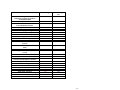
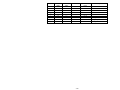
By product design and definition Micro-Manager Pro has all of the features and
functionality of Micro-Manager plus additional features. While both products may change and
mature this assumption is expected to remain valid. Please refer to the table below.
To verify which edition you have, see the Help About window of the program. When the
professional configuration is in use, a clear indication of the “Professional” version will be
indicated.
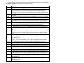
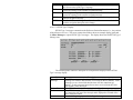
- 11 -
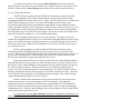
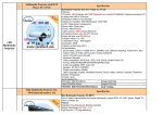
Current Features
Micro-Manager
32 bit multitasking & multithreaded
architecture running on Windows
95/98/ME/NT/2000
Windows Graphical User Interface
Choice of GUI (manual) or Command
Line (automatic) interface
Ring file data control
Receiver data file management
Session programming
Receiver script file uploading feature
Powerful terminal window capability
User configurable alerts
Reliable firmware uploads
Z-modem protocol for data transfers
File translations to Ashtech or RINEX
formats
RTCM base station configuration control
status
Built in user safeguards
User configurable real time information
screens
Direct receiver connection
Remote (modem) receiver connection
Full control over dialing parameters and
hardware handshaking for modems
Dialing directory facilities
Modem settings
RINEX Site/Header table Feature
Post-Download Command Feature
D-file to Met. RINEX file
XYZs_FTP Activated
15-Minute RINEX 2.2 File Naming
iCGRS Network Config. Support
TRUMP Activated
Yes
Micro-Manager
Pro
Yes
Yes
Yes
Yes
Yes
Yes
Yes
Yes
Yes
Yes
Yes
Yes
Yes
Yes
Yes
Yes
Yes
Yes
Yes
Yes
Yes
Yes
Yes
Yes
Yes
Yes
Yes
Yes
Yes
Yes
No
No
Yes
Yes
Yes
No
No
No
No
No
No
Yes
Yes
Yes
Yes
Yes
Yes
Yes
Yes
Yes
Yes
Yes
Yes
- 12 -
Chapter 1
Introduction to Micro-Manager
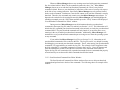
1.0 OVERVIEW
Micro-Manager is a PC based program that was designed for the management of
remotely and locally operated µZ-Family of GPS receivers. Micro-Manager software provides
users with the ability to control essential receiver parameters and logging features while allowing
full access to all of the data stored within the receiver. Users can interface with the program
using its state-of-the-art Graphical User’s Interface (GUI) or through command-line options which
facilitate automation. The result is an advanced reference station system capable of managing
numerous GPS receivers. These receivers can be located locally or, through its modem access
features, virtually anywhere in the world.
Micro-Manager was designed to run on Windows 95/98/ME/NT/2000 platforms. While
capable of operating on all of these platforms, Micro-Manager is 32-bit in nature and takes full
advantage of the preemptive multi-tasking and multi-threading capabilities of the Windows NT
and 2000 platforms. These features provide the user with a stable and secure platform that
requires minimal maintenance. Micro-Manager should run equally well on Windows XP.
Micro-Manager currently supports the Ashtech µZ-Family of GPS receivers. This
includes the µZ-CGRS and µZ-Surveyor receivers. It has been designed to allow both direct
connections (i.e., via RS-232 cables) to the GPS receiver and remote connections through
modems. Micro-Manager offers extensive modem configuration options and, as such, will
support a wide variety of modems. Furthermore, the modem configuration options support a wide
variety of installation needs. For example, one installation of Micro-Manager is configured to
use a spread-spectrum modem. That modem employs a TDMA network access scheme and
utilizes several repeaters to reach some of the remotely located receivers. Without the availability
of the extensive configuration options, such an installation may not have been possible.
Micro-Manager is capable of exploiting the following major features of the µZ-Family
of GPS receivers.
1)
2)
3)
GPS data collection and data file storage.
GPS data collection “configuration” parameters including satellite filtering and site
information.
Session programming features.
- 13 -
4)
5)
6)
7)
8)
9)
Receiver communication port configuration.
RTCM configuration and control.
Remote Firmware Uploading.
Parameters which control the protocol used in the transfer of GPS data.
iCGRS Receiver Networking Configurations.
Auto-unpacking of U-Files that have been FTP pushed via iCGRS receivers (using
the utility program TRUMP provided with Micro-Manager).
Using Micro-Manager, users can configure receiver-logging sessions. This feature,
referred to as the Session Programming feature, establishes the time periods during which GPS
data will be recorded and the parameters governing that collection. For example, the user can
define a data collection session beginning at 1:00 AM every day, lasting 1 hour, based upon a 1second data epoch, with an elevation mask of 5 degrees. The user could then define another data
collection session (up to 24 sessions) beginning at 10:00 AM every day, lasting 4 hours, based
upon a 20-second data epoch, with an elevation mask of 10 degrees, and storing data only when
there are 4 or more satellites.
Micro-Manager also can be called from a command-line. This facilitates automatic
and/or unattended management of local or remote receivers. Using this feature, one can command
Micro-Manager to dial-up and download receiver data. Furthermore, you can instruct MicroManager to delete the successfully downloaded files from the receiver’s memory, thereby
enabling further data collection within the receiver. For Windows NT users, the “AT” command
of the “Scheduler” service can be used to schedule runs of Micro-Manager. In fact, one can set
up a batch file containing commands to dial your entire set of remote receivers and then use the
AT feature of Windows NT to schedule the execution of that batch program. Users desiring more
elaborate and/or user-friendly scheduling features can employ commercially available scheduling
programs, such as Norton Scheduler.
Micro-Manager contains a Post-Download Command feature that allows users to
configure and call applications that may operate on data created by Micro-Manager. For
example, one can configure Micro-Manager to call an FTP program that will create target
directories on an FTP server and then upload data files created by Micro-Manager to that FTP
Server.
When it becomes necessary to change your receiver’s firmware, you will find that Thales
Navigation has paid particular attention to providing reliable and stable firmware uploads. That
is, Micro-Manager contains a built in firmware uploading capability that utilizes a protective
firmware upload protocol, reliable firmware file formats, and very stringent firmware crosscheck
procedures. The result is a reliable means of upgrading your receiver’s firmware either through a
direct connection or a remote connection.
Additionally, Micro-Manager has been designed to operate in concert with other
commercially available software packages, such as Bulletin Board Systems (BBS) and FTP
servers. It must be emphasized that Micro-Manager does not, by itself, contain all of the tools
necessary for automated Internet and BBS operation. Rather, it has been designed to work in
- 14 -
concert with such packages. Thales Navigation recommends obtaining commercially available
and well-recognized software systems to support these needs.
Micro-Manager is further extended in that it supports features of the iCGRS receiver.
Micro-Manager contains a special iCGRS network configuration screen that assists in the
network configuration of an iCGRS receiver. Furthermore, the utility program TRUMP, which is
supplied in the suite of utilities included with Micro-Manager, can be used to automatically
convert U-Files into it constituent processing files (e.g., Ashtech B-, E-, and S-Files as well as
RINEX data files). That is, TRUMP was designed to be a resident program on the target
system/network of U-Files pushed to an FTP site by an iCGRS receiver. When new U-files arrive
on that system/network, TRUMP automatically will perform the conversions specified by the
operator. For complete details on TRUMP, please see Appendix H.
1.1 Minimum System Requirements
Micro-Manager requires a Windows 95/98/ME/NT/ 2000 based computer. While
Micro-Manager requires less than 10 megabytes of memory to run, Windows platforms impose
higher minimums. It is recommended, for performance reasons, that your computer have no less
than 32 megabytes of RAM memory for Windows 95/98/ME and 64 megabytes for Windows
NT/2000 platforms. Thales Navigation strongly recommends either a Windows NT or Windows
2000 platform because of the true 32-bit nature of these platforms .
Your disk space requirements will vary depending upon your unique installation and data
collection needs. Micro-Manager actually requires less than 25 Megabytes of disk space to store
the program and its ancillary files, but it is recommended that your available disk space be much
larger to accommodate your data storage needs. Storage solutions such as ZIP (100 MB or 250
MB) and JAZ (1 or 2 GB) from Iomega provide but two examples of alternate storage solutions.
To optimize the performance of Micro-Manager, please give special consideration to the
PC you choose to run the software. It is important to choose a leading brand system to avoid less
capable components such as serial cards often found in cheap knock-offs. Although MicroManager will run on most all Intel (and AMD) processors (486 and up), it’s performance may be
superior on a well-built Pentium system specifically designed for Windows NT/2000.
To communicate with remotely located receivers, you will need a minimum of two
modems: i.e., one for the computer and one for every remotely located GPS receiver. Thales
Navigation recommends that you utilize modems from the same manufacturer throughout your
installation to avoid compatibility problems. Furthermore, Thales Navigation recommends that
you use either US Robotic Courier or Sportster Modems. Check with Thales Navigation
regarding other modems, including spread-spectrum type radio modems.
It should be emphasized that Thales Navigation does not support all modems; so it is
necessary to verify that the modems you wish to use are supported.
- 15 -
1.2 Demo Modes of Micro-Manager
There are two basic modes of Micro-Manager: fully operational and demonstration (i.e.,
demo). This document applies to both modes. Demo modes, which are freely distributed over the
Internet or provided on diskette, have a greatly reduced capability when compared with a fully
operational program but do not require a sentinel key. Demos will differ from operational
programs by disallowing at least the following: (1) all file download and delete features, (2) the
editing of receiver control parameters, and (3) the command-line features. Basically the demos
permit one to observe but not to accomplish.
One can obtain a Demo Micro-Manager from the Reference Station link on the Ashtech
web page at the following address:
http://www.ashtech.com
- 16 -
Chapter 2
Installation Instructions
2.0 INSTALLATION OVERVIEW
From a total system perspective, there are two primary sides of the installation process: 1)
installing hardware and 2) installing software. The primary purpose of this manual is to describe
the installation and use of the Micro-Manager software package. We will not provide in-depth
installation guidelines and steps for hardware installation; we refer you to the appropriate
computer and receiver manuals for details. We will, however, introduce some important GPS
receiver, modem and computer installation issues as they relate to the operation of the MicroManager software package.
Again, in this section we describe the installation as it relates to Micro-Manager. Please
note, however, that the utility programs supplied with Micro-Manager include TRUMP, which
has primarily been designed to be used in conjunction with iCGRS receivers. The iCGRS
receivers have been designed to allow one to push (via FTP) receiver U-Files to FTP sites.
TRUMP is described in Appendix H and, unless otherwise noted (e.g., Appendix H), this manual
does not pertain to the iCGRS receiver. As such, this section does not describe the configuration
of the iCGRS receiver network configuration (hardware or software). Section 4.1.5.4.2 of this
manual does describe a feature of Micro-Manager that assists in the network configuration of an
iCGRS receiver.
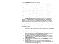
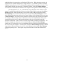
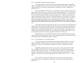
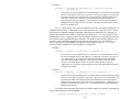
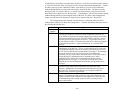
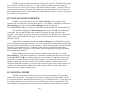
2.1 Hardware Installation
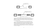
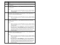
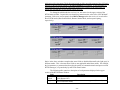
Micro-Manager has been designed with two primary configurations in mind: 1) direct
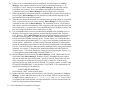
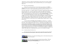
connections and 2) remote connections. Figures 2.1.A and 2.1.B provide basic block diagrams for
these configurations. Figure 2.1.A provides a direct connection (also called a local receiver
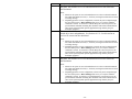
connection) block diagram while Figure 2.1.B provides a remote receiver connection block
diagram.
- 17 -
RS-232 Cable
GPS
Receiver
Personal
Computer
Figure 2.1.A: Direct Connection
Telephone Connection
Personal
Computer
modem
modem
GPS
Receiver
Figure 2.1.B: Remote Connection
As can be seen in the above block diagrams, the primary difference between these two
configurations is the use of modems to establish the link between the Personal Computer and the
GPS Receiver. For details on connecting modems to your GPS receiver, please consult the
appropriate receiver manual. Likewise, the manuals of your Personal Computer should describe
how to connect/install modems.
To communicate with remotely located receivers, you will need a minimum of two
modems: i.e., one for the computer and one for every remotely located GPS receiver. Thales
Navigation recommends that you utilize modems from the same manufacturer throughout your
installation to avoid compatibility problems. Furthermore, Thales Navigation recommends that
you use either US Robotic Courier or Sportster Modems. Check with Thales Navigation
regarding other modems, including spread-spectrum type radio modems. It should be emphasized
that Thales Navigation does not support all modems; so it is necessary to verify that the modems
you wish to use are supported.
- 18 -
The particular type of receiver, and, for certain receiver types, the communication port of
the receiver used for Micro-Manager functions, plays a key role in the Micro-Manager
configuration process. This is because there are slight hardware variations in the various µZFamily of GPS receivers. With the exception of Port A of µZ-CGRS receivers, the DTR/DSR
hardware handshaking lines ARE NOT implemented. It is essential to understand this because
many modems are pre-configured so that when the DTR line is dropped, it signals the modem to
terminate a telephone connection. Therefore, when using µZ-CGRS receivers it is suggested that
you connect the receiver’s modem to Port A of the receiver. When connecting a modem to a nonµZ-CGRS receiver (or Ports B through D of a µZ-CGRS receiver), ensure that you configure the
receiver to instruct its modem to ignore the DTR/DSR signal (See Section 4.1.5.4.3). For direct
connections, this is key because Micro-Manager must be configured according to the availability
of the DTR/DSR flow control of the receiver or receiver port. Section 3.1.1.3.5 describes the
configuration of the DTR/DSR hardware flow control for direct connections.
2.2 Micro-Manager Installation
In this section, we describe the installation of the Micro-Manager software program (and
its ancillary programs and files).
For most users of Micro-Manager the installation is very straightforward. The
installation uses an industry recognized installer program. If for any reason you decide to remove
Micro-Manager (such as to install an upgrade to Micro-Manager), it can be removed (along
with all of its support components) using normal Windows 95/98/ME/NT/2000 software uninstall
mechanisms. Please see the end of this section for details on uninstalling Micro-Manager.
Please note that when installing Micro-Manager on a Windows NT or Windows 2000
machine, it is necessary to install Micro-Manager under an account that has full administrative
privileges (such as the Administrator’s account). If you attempt to install Micro-Manager under
an account that does not have full administrative access, Micro-Manager will not install and run
properly. This is because the Micro-Manager installer needs to add device drivers for its
sentinel key.
During the installation of Micro-Manager the following major components will be
installed:
•
•
•
•
Micro-Manager Program files
Sentinel Drivers
Micro-Manager Sound Files
Micro-Manager Ancillary/Support Program Files
The program files include the executable program and its configuration files. The sentinel drivers
are required to allow Micro-Manager to communicate with its sentinel key. In fact, without
these drivers, Micro-Manager would not be expected to run. This sentinel key comes standard
with each copy of the program. The sentinel key allows Micro-Manager and its support utilities
- 19 -
to run on a single workstation. Please note that multiple copies of Micro-Manager can be run on
a single workstation based upon a single sentinel key (i.e., without the need of additional sentinel
keys). Furthermore, there is virtually no limit to the number of remote receivers that can be
controlled using a single copy of the program.
The Micro-Manager sound files are a set of WAV files that Micro-Manager can be
configured to play when certain events occur (see Section 3.1.6.1). The user selects which sound
files to play, in each situation, during the configuration of Micro-Manager.
The ancillary program files, installed when Micro-Manager is installed, include the
programs UPACKU12.exe, XYZAshRx.exe, XYZs_FTP.exe, and TRUMP.exe. The programs
UPACKU12.exe and XYZAshRx.exe convert receiver memory files to standard Ashtech GPS
data files and to RINEX, respectively. The program XYZs_FTP.exe is a command-line callable
program that can be used with the Post-Download feature of Micro-Manager to FTP files to and
create directories on remote FTP servers (assuming that the system/network administrator of that
system has given you permission to do so). TRUMP, which described in Appendix H, has
primarily been designed with the iCGRS U-File FTP push capability in mind. That is, iCGRS
receivers can be configured to push data to an FTP site. When TRUMP is running on that FTP
system, it can automatically convert the received U-Files into normal data processing files (e.g.,
Ashtech B-, E-, and S-Files and RINEX files) and run Post-Convert Commands after those files
have been converted.
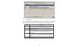
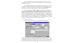
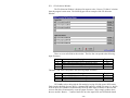
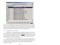
2.2.1 The Installation Process
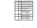
The Micro-Manager Installer comes in one of three typical forms: 1) a CD-ROM based
installer; 2) a diskette based installer; or 3) an installer suite downloaded over the Internet (from
the Ashtech Web page). The CD-ROM is the most common method used, especially for new
installations. The Internet/Web approach is the most common method used to obtain updates.
Each of these installers has a common executable program (i.e., “SETUP.EXE”) that is used to
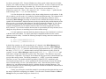
control the installation. To start the installation process, one simply launches that executable.
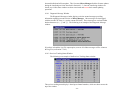
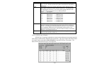
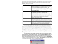
The table that follows provides information related to the three typical installer forms.
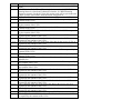
- 20 -
Form
CD-ROM
Diskette
Internet
Download
Installer Information
The top-level directory of the CD-ROM contains three items: 1) a file named
“Install.txt”, 2) a “MicroMgr” folder; and 3) a “Remote32” folder. The file
“Install.txt” describes how one installs various programs from that CR-ROM
(however, we will describe herein how one installs the Micro-Manager
program). The “MicroMgr” and “Remote32” folders contain the files and
folders needed to install Micro-Manager and Remote32, respectively.
Please note those that have purchased Micro-Manager Pro can install and
run Remote32 (i.e., if you did not purchase the Pro version, you can install
Remote32 but it will fail to run).
Within the CD-ROM “MicroMgr” folder are a set of folders (e.g., “Disk1”,
“Disk2”, “Disk3”, etc.). Simply browse (using Explorer or a like approach)
into the “\MicroMgr\Disk1” folder and double-click the program
“SETUP.EXE”.
To install Micro-Manager onto your computer, insert the Micro-Manager
installation diskette labeled “Micro-Manager Install Disk 1” into the A (or
B) drive of your computer. Press the “Start” button and select “Run”. Use
the “Browse” command to locate and run the “Setup” program on the diskette
located in the A (or B) drive of the computer.
Micro-Manager installer files downloaded from the Ashtech Web page will
likely be in the form of a single PkZipped file. Simply unzip this file into the
same temporary directory (that you create) on your hard drive. Then browse
(using Explorer or a like approach) to the temporary folder where the file was
unzipped and double-click the program “SETUP.EXE”.
Note: After the installation has completed successfully, you can remove the
files in the temporary folder. It is suggested, however, that you make
a backup copy of these files in case you later need to reinstall the
program.
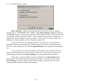
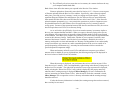
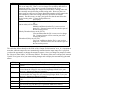
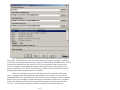
Once you have started the “SETUP.EXE” program (described in the above table), the
installer program will start. The install program guides you through the installation of the MicroManager software. At each step you will be given an opportunity to accept default options or
tailor these to your individual needs. You will be required to enter your 8-character serial
number. For the CD-ROM distribution form, the serial number is located on the CD-ROM jewel
case (and the original software container box). For the diskette distribution form, the serial
number is located on each of the Micro-Manager installation diskettes (and the original software
container box). For Internet forms, the serial number must be obtained from the original form
(CD-ROM or diskette) shipped to you. The following is an example Micro-Manager serial
number.
KF004561-MICROM-011598
The first 8 characters of the serial number are the numbers that should be entered during the
installation process. In the above example the Micro-Manager serial number that one would
enter is KF004561. Please note that without the proper serial number you will not be able to
continue the Micro-Manager installation.
- 21 -
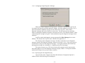
During the installation of the Micro-Manager program and data files, you will be asked
two questions:
1)
2)
Do you want a Micro-Manager entry in the Windows Start Program menu?
Do you want a shortcut to Micro-Manager on your desktop?
Answering no to either question does not prohibit you from later manually activating or
deactivating the features. Likewise, answering yes to either question will not prohibit you from
manually deactivating the features. Manually activating and deactivating these features can be
accomplished through standard Windows configuration parameters (such as creating shortcuts) at
any later time.
If you decide to add Micro-Manager to the Windows Start Program menu, then you will
be able to quickly launch Micro-Manager using the Windows “Start” button. If you choose to
have a Micro-Manager shortcut added to your desktop, then the installer will place the program
icon onto your desktop. To launch the program from the desktop, you will simply need to doubleclick the program icon. In both cases, the link to the program is installed without any additional
command-line parameters (i.e., double-clicking the program icon will place the program into its
GUI mode, rather than its command-line mode).
2.2.1.1 Installing the Sentinel Key
Before actually running Micro-Manager, you will need to install the software sentinel
key. Please note that Micro-Manager will not run without this sentinel key. Also note that you
cannot start Micro-Manager with the key and then later remove the key while Micro-Manager
is running. The software sentinel key is installed by attaching the end of the sentinel key labeled
éCOMPUTERé to a parallel printer port of your computer. Please tighten the screws of the
sentinel key to securely connect the key to your computer. If a printer is connected to your
computer, attach that cable to the sentinel. If the sentinel cannot be installed because of an
obstruction behind the computer, you can place the sentinel key later in the parallel sequence (for
example, you could attach the sentinel key to a DB-25 male to DB-25 female cable which is
connected to your computer’s parallel port). To ensure a good connection between the computer,
the sentinel key and other parallel devices, use only IEEE standard parallel printer cables.
The sentinel key allows Micro-Manager to run on a single workstation. As stated
earlier, multiple copies of Micro-Manager can be run on a single workstation without need of
additional keys.
2.2.1.2 Uninstalling Micro-Manager
Micro-Manager and all of its components can be uninstalled via the “Add/Remove
Programs” feature of the “Control Panel” in Windows. Please note that Micro-Manager must be
removed prior to installing a new version. The Install Shield program, which installs MicroManager, does not detect and remove old versions.
- 22 -
Chapter 3
Configuring Micro-Manager
3.0 CONFIGURATION OVERVIEW
Before actually running Micro-Manager, you will need to install the software sentinel
key. Please note that Micro-Manager will not run without this sentinel key. Also note that you
cannot start Micro-Manager with the key and then later remove the key while Micro-Manager
is running. The software sentinel key is installed by attaching the end of the sentinel key labeled
éCOMPUTERé to a parallel printer port of your computer. Please tighten the screws of the
sentinel key to connect the key securely to your computer. If a printer is connected to your
computer, attach that cable to the sentinel. If the sentinel cannot be installed because of an
obstruction behind the computer, you can place the sentinel key later in the parallel sequence (for
example, you could attach the sentinel key to a DB-25 male to DB-25 female cable which is
connected to your computer’s parallel port). To ensure a good connection between the computer,
the sentinel key and other parallel devices, use only IEEE standard parallel printer cables.
The sentinel key allows Micro-Manager to run on a single workstation. Multiple copies
of Micro-Manager can be run on a single workstation without need of additional sentinel keys.
Prior to connecting to the GPS receiver, Micro-Manager needs to be configured to suit
your data collections needs. Please note that this configuration process is extremely important, as
the Micro-Manager factory defaults will probably not meet your needs.
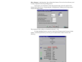
The Micro-Manager configuration information is stored in 3 files:
1)
2)
3)
MICROMGR.PNM;
MICROMGR.MDM; and
MICROMGR.INI.
All of these configuration files are located in the same directory where the main program
file (i.e., MICROMGR.EXE) is stored. The file named MICROMGR.PNM stores the telephone
numbers to be dialed to reach each of your remote receivers. The file named MICROMGR.MDM
stores all of the configuration information associated with each of the modems you have
configured to be used with your PC. Finally, the file named MICROMGR.INI contains all other
configuration information related to the program.
Micro-Manager automatically updates the contents of the configuration files as the
operator makes changes using the “configuration” menus. Changes are written to these files so
that the configuration may be recalled at the start of the next run of the program. In this way,
- 23 -
once the desired configuration is set, the operator no longer needs to change it -- unless, of course,
it needs to be altered to support a new configuration. The “Configuration” sub-menus of the
Micro-Manager program are used to set the majority of these parameters. Details of the contents
of the Configuration sub-menus will be provided in later sections of this document.
The above mentioned configuration files are text (i.e., ASCII) files. As such, the
configuration can also be modified with any text file editor. However, you are strongly
discouraged from making configuration changes using this approach. In fact, after you get
Micro-Manager configured as desired, it would be prudent to make a backup copy of these
configuration files. Should you need to modify any of these files with a text editor, please verify
that you have a backup copy before editing them.
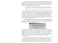
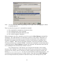
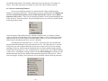
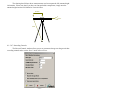
3.1 Configuration Menus
Most Micro-Manager parameters are set through the main menu "Configuration" option.
The “Configuration” drop-down menu is divided into 6 different selections. These 6 selections
become available when “Configuration” is selected (a drop-down menu appears).
The following Sub-Sections describe each of the 6 configuration windows (i.e., sub-menus).
It is intended that Micro-Manager be configured before connecting to a receiver. One
can, however, change the configuration of the receiver while Micro-Manager is connected to
that receiver. Special features have been built into Micro-Manager to change the GPS receiver’s
parameters while Micro-Manager is connected to the GPS receiver. These will be described in
later sections.
Earlier we stated that it is generally expected that Micro-Manager be configured before
it is actually connected to a receiver. However, whenever a valid communication port is specified
in its configuration files, Micro-Manager will, upon startup, open that communication port and
attempt to determine the type of receiver, if any, that is connected on that port. For introductory
users of this package, this may be a somewhat confusing point. However, experienced users will
- 24 -
find this improves their productivity by requiring fewer steps to begin their work. This topic will
be described in more detail later in this document (see Sections 3.1.1, 3.1.6.5, and 4.1.2)
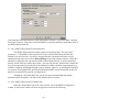
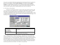
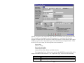
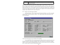
3.1.1 PC Communication Port Settings
The PC (or Personal Computer) Communication Port Configuration window allows the
operator to set the communications port parameters governing the connection with the GPS
receiver. The items configured through this window affect the settings of the computer
communication port over which Micro-Manager is communicating with the GPS receiver, and
not the port settings of the GPS receiver (see Section 4.1.5.4.3).
The Communication Port Configuration window permits the editing of the following
communication parameters:
1) The PC communication port (labeled "Comm Port”);
2) The PC communication port speed (labeled "BAUD”);
2) Advanced communication options (labeled "Advanced …”);
When making configuration changes through this window (or the window reached by
pressing the “Advanced …” button), keep in mind that you are configuring the communication
port of the local PC (not the parameters of the device attached to that port). However, your
configuration settings will depend on the device (i.e., either a modem or a GPS receiver) attached
to the communication port.
Upon accepting the changes to this window, by pressing the OK button, Micro-Manager
will immediately attempt to configure and open the communication port of the local PC. Please
note that when you accept the port settings, if any of the receiver status windows are open (see
Sections 4.1.4 through 4.1.4.7), Micro-Manager will immediately attempt to obtain that status
data. This is important because if a live GPS receiver is not connected to that serial port (or that
receiver’s communication port is not operating at the same communication speed or the
connection to the receiver is normally done through a modem), then Micro-Manager will begin
generating error messages. In other words, when the receiver status windows are open, MicroManager expects the receiver to be connected and begins issuing commands to obtain the status
data. Because the receiver is not attached (or is configured at a different communication speed),
no responses are forthcoming and, thus, Micro-Manager believes that there are errors in
communication. To avoid these problems, simply close the receiver status windows whenever
changing the PC’s communication port settings.
- 25 -
Upon pressing the OK button in this window and assuming Micro-Manager is currently
aware that it is directly connected (i.e., not connected via modem) to a GPS receiver, MicroManager will perform some additional processing. To fully understand the discussion to follow,
some background information is required. There were two somewhat opposing design goals in
the early stages of the Micro-Manager development effort:
1) To allow users to utilize some minimal features of the program with other Thales
Navigation (i.e., non µZ-Family) GPS receivers and as a general terminal program;
and
2) To boost the user’s productivity by performing some behind the scenes processing.
These two goals are somewhat conflicting because, in order to reach the second goal, one must be
communicating with the receiver (i.e., the communication rates of both the receiver’s port and the
computer’s port must be the same). In order to reach this second goal, Micro-Manager must
determine the receiver type whenever possible. Micro-Manager achieves this by issuing receiver
specific query commands over the communication port. However, this conflicts with the first
goal, particularly to the use of the program as a general terminal program. Thus, when you
change the communication configuration of the local computer (through this window), the settings
may not be compatible with those of the receiver.
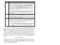
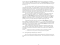
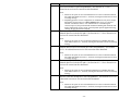
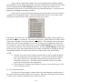
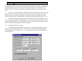
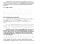
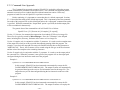
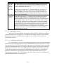
When Micro-Manager is directly connected to a GPS receiver, and Micro-Manager
knows that it is connected to a µZ-Family GPS receiver, as would be indicated by the lower-right
portion of the status bar (see Section 4.1.1.4), any changes to the communication configuration
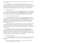
will result in the issuance of the following prompt:
This prompt is really indicating that you are changing the communications settings of your local
computer port such that you may not be able to communicate with the receiver. Furthermore, the
point of the prompt is to determine if you want to attempt to automatically set the communication
configuration of the receiver to match that of your computer. If you answer “Yes”, MicroManager will first set its local port configuration, then go through a polling process to determine
the receiver’s type and communication parameters (because you may have, through this window,
selected a different local computer port), and then command the receiver to desired
communication speed.
Please be advised that the polling process used to detect the receiver’s port speed may fail
on some USB to Serial device converters. That is, some of these converters do not fully
implement the expected (and standard) features of serial communications devices. When this
occurs, the polling process will fail, but you will not likely get an immediate visual clue of this
failure. You will likely only notice the failure when you try to access the receiver through the
- 26 -
receiver status screens or receiver configuration screens of Micro-Manager. When you have
such a device, and it does fail as described, you can still use that device, but you cannot use the
polling process. Instead you will need to manually implement the polling process. That is, you
can use the “PC Communication Port Settings” window (described above) to change the local PC
BAUD rate to various speeds until you find the speed of the receiver. Then, go to the “Receiver
Communications Port Settings” window (see Section 4.1.5.4.3) and change the “Active” receiver
port speed to the speed desired. Finally, use the “PC Communication Port Settings” window to
set the Local PC communication speed to the desired speed.
Additionally, there are slight hardware differences among the members of the µZ-Family
of receivers. One should be aware of these hardware differences when making changes to the
communication parameters. These should be only of concern when directly connected (i.e., NOT
connected via modem) to the GPS receiver. Specifically, with the exception of Port A of µZCGRS receivers, the DTR/DSR hardware handshaking lines ARE NOT implemented. As such,
Micro-Manager must be configured according to the availability of the DTR/DSR handshaking
of the receiver or receiver port. Section 3.1.1.3.5 describes the configuration of the DTR/DSR
hardware handshaking for direct connections.
Finally, when Micro-Manager has established a modem connection to the receiver (see
Section 4.1.2), you are strongly advised not to change the communication parameters of the local
computer (i.e., you should avoid using this window). Changing these communication parameters
when connected via modem may cause the modem to break the telephone connection. If you must
change the communication speed, you are strongly encouraged to manually disconnect (see
Section 4.1.3), change the configuration of the local PC as desired, and then re-dial the telephone
number of the target GPS receiver (see Section 4.1.2).
3.1.1.1 Configuration | Port Settings / Comm Port
The port selection allows the operator to specify the communications port of the computer
used to communicate with the Ashtech receiver. The selectable values are "COM1" to “COM16”.
3.1.1.2 Configuration | Port Settings / BAUD
The BAUD selection establishes the communications speed of the communications port
of the computer used to communicate with the Ashtech receiver or the modem through which
Micro-Manager communicates with the receiver. The selectable values are 300, 600, 1200,
2400, 4800, 9600, 19200, 38400, 57600 and 115200.
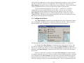
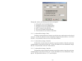
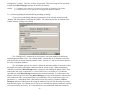
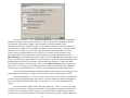
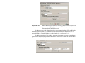
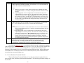
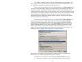
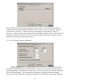
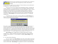
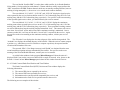
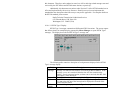
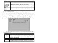
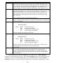
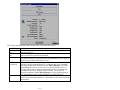
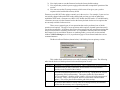
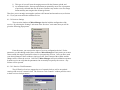
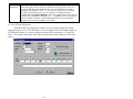
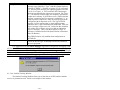
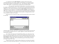
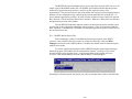
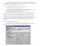
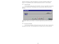
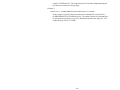
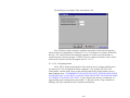
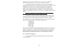
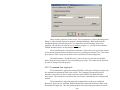
3.1.1.3 Configuration | Advanced Settings
Pressing the “Advanced…” button of the PC Communications Configuration window
accesses the advanced communication settings. Upon pressing this button you will be presented
with a window similar to the following:
- 27 -
Through this window, the following items can be configured:
1)
2)
3)
4)
5)
6)
Parity used in serial communications;
Data Bits used in serial communications;
Stop Bits used in serial communications;
RS-232 control line handshaking;
The level of Windows interaction; and
Turn-around wait time for direct connections.
3.1.1.3.1 Advanced Port Settings / Parity
The Parity selection allows the operator to specify the parity mode used over the selected
serial port. To date, all Ashtech receivers communicate using the no parity mode (i.e., the “None”
selection). The permissible values are Even, Odd, Mark, and None.
3.1.1.3.2 Advanced Port Settings / Data Bits
The Data Bits selection allows the operator to specify the number of data bits used when
communicating over the selected serial port. To date, all Ashtech receivers communicate using 8
data bits. The permissible values are 7 and 8 data bits.
3.1.1.3.3 Advanced Port Settings / Stop Bits
The Stop Bits selection allows the operator to specify the number of stop bits used when
communicating over the selected serial port. To date, all Ashtech receivers communicate using 1
stop bit. The permissible values are 1, 1.5, and 2 stop bits.
- 28 -
3.1.1.3.4 Advanced Port Settings / Use CTS/RTS Hardware Flow Control
The CTS/RTS Hardware Flow Control checkbox allows you to specify whether or not the
normal CTS/RTS hardware flow control handshaking is enabled. In most configurations, this
checkbox should be checked. Those who uncheck this checkbox should have clear rationale as to
why they should eliminate the CTS/RTS hardware handshaking. For example, there are certain
modems that do not employ the CTS/RTS hardware handshaking. In these cases, MicroManager needs to be made aware of the difference.
3.1.1.3.5 Advanced Port Settings / Use DTR/DSR Hardware Flow Control
The DTR/DSR Hardware Flow Control checkbox allows you to specify whether or not
the normal DTR/DSR hardware flow control is enabled.
For direct connections with a GPS receiver (See Section 2.1) you will need to alter this
depending on the receiver type or the port of the particular receiver that will be used. This is
because there are some slight hardware variations between different models of µZ-Family
receivers. With the exception of Port A of µZ-CGRS receivers, the DTR/DSR hardware
handshaking lines ARE NOT implemented. As such, Micro-Manager must be configured
according to the availability of the DTR/DSR handshaking of the receiver or receiver port. For
most users, this checkbox should be unchecked (i.e., disabling the use of the DTR/DSR
handshaking for flow control).
For remote connections, you will need to set this configuration depending on the type of
modem that will be used to establish the remote connection. For nearly all types of modems, you
will need to disable this setting (i.e., have the checkbox unchecked). Please see the appropriate
modem manual for details on its DTR/DSR signal use.
In most configurations, this checkbox should be unchecked (i.e., disabling DTR/DSR for
flow control). Those who check this checkbox should have clear rationale as to why they should
use the DTR/DSR hardware handshaking. For example, there are certain Ashtech receivers and
modems that do not employ the DTR/DSR hardware handshaking for flow control. In these cases,
Micro-Manager needs to be made aware of the difference.
3.1.1.3.6 Advanced Port Settings / Direct Connection Turn-Around Time
Each Micro-Manager installation can exhibit slight variations in system performance,
particularly in the area of RS-232 data communications. Poor communication links, operating
system loads and other such factors can influence the RS-232 communication performance. The
default configuration of Micro-Manager should handle nearly all of these variations.
The “Direct Connect Turn-Around Time” parameter specifies the maximum amount of
time (in milliseconds) between the issuance of a command to the receiver and receipt of a
response to that command. Micro-Manager permits 3 non-response failures for each command
before reporting an error. Thus, if you tend to get a high number of errors during normal
operations with a GPS receiver, particularly during a file download operation, then you will want
- 29 -
to increase the turn around time. On the other hand, increasing the number to an overly large
value will cause Micro-Manager to take a long time to report errors. For example, if you set the
parameter to 9000 (or nine seconds), then when there are truly errors in data communications, it
will take up to 27 seconds to start reporting the errors. In most cases, you will not need to modify
this parameter.
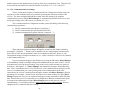
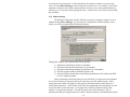
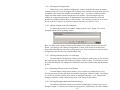
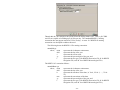
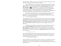
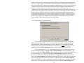
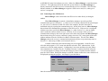
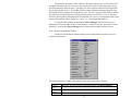
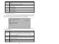
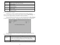
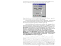
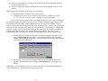
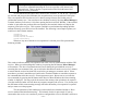
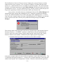
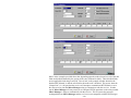
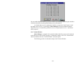
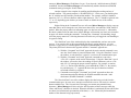
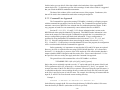
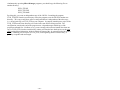
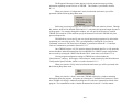
3.1.2 Modem Settings
The Modem Configuration window allows the operator to configure a single or a set of
modems used by Micro-Manager. By selecting the “Configuration | Modem Settings” menu
option, you will be presented with the following window.
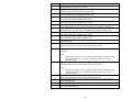
Through this window, you can perform the following tasks:
1)
2)
3)
4)
5)
Add, Delete and Rename instances of modems;
Edit the modem initialization strings for each modem;
Edit the modem dialing and hang-up parameters for each modem;
Edit the expected modem command responses; and
Edit specialized control features used during communication with modem and GPS
receiver using that modem.
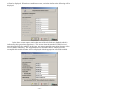
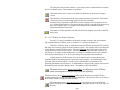
Before continuing with the description of each edit field, it is important to note that there
are two special character sequences that can be entered as part of the modem strings. Often
strings sent to the modem to configure it and responses from that modem contain special (i.e.,
non-printable) characters. ASCII control codes (listed in Appendix B of this document) are used
to represent these special characters. For example, the end of an initialization string often
requires a carriage return character. The ASCII control code for this character is ^M (i.e.,
normally entered by pressing the keyboard “control” character and then, while holding the control
- 30 -
key down, pressing the “M”). Because Windows uses these special control sequences for other
purposes, one cannot enter these codes directly into the edit field. As such, we must represent the
control character in the edit fields in another way. We have chosen to use caret character to
represent the control character. Thus, to enter ^M, you enter the caret character (i.e., “^”)
followed by capitol “M”. That is, ^M is entered as “^M”. To enter a single “^” symbol into the
modem strings, enter “^^” (i.e., two caret characters).
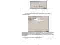
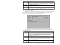
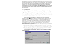
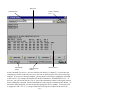
It is also often desired to introduce a delay when sending characters to the modem. In the
above window, you will see the “@” symbol in a modem initialization string. This character will
not be transmitted to the modem. Rather, the characters preceding the @ character will be
transmitted, Micro-Manager will delay an amount of time, and then the characters after the @
symbol will be transmitted. Both the character used to represent the delay and the duration of the
delay are set by you using the “Miscellaneous” tab of this window (See Section 3.1.2.8). Please
note that all instances of the delay character will be translated to delays. That is, there is no
sequence through which you can send the character when it has been assigned the role of the
delay character. If you need to send the character that is represented by the delay character, then
change the delay character to something not used in the modem strings.
It is also important to note that the delay character that you select should not be confused
with that used by the modem. To explain, most Hayes-compatible modems use the comma
character to insert a delay. Consider the following examples of strings sent to the modem from
Micro-Manager:
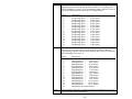
1) ATDT 9@@@18005551212^M
2) ATDT 9,,,18005551212^M
In both of the examples, we will assume that the “@” character is the Micro-Manager delay
character and the comma character is the modem delay character. In case 1, Micro-Manager
sends the string “ATDT 9”, waits three times the delay programmed for the “@” symbol, sends
the string “18005551212”, and then sends a carriage return character in place of the ^M
sequence. In case 2, Micro-Manager sends the string “ATDT 9,,, 18005551212” and
then sends a carriage return character in place of the ^M sequence. The difference may not be
obvious but it is important. For example, most modems do not process many commands until the
receipt of the carriage return. The dialing command (i.e., “ATDT”) is one such command.
Therefore, in case 1, the modem would end up dialing “918005551212” immediately after
receiving the carriage return (i.e., the @ symbol has no effect other than to increase the amount
time to send the string). In case 2, the modem dials 9, waits 3 times the delay for the comma
character (see your modem manual for details), and then dials the remaining characters. The
latter case shows how one uses the dialing sequence first to obtain an outside line and then to dial
the desired telephone number.
Finally, you will need to consult the manual for your modem to determine the how to and
the strings required for configuring your modem. You can use the Terminal Window of MicroManager to test your modem strings (see Section 4.1.6).
- 31 -
3.1.2.1 Selecting an Existing Modem
When you leave the “Modem Configuration” window using the OK button, the modem
currently selected for use by the program will be shown as the selected entry in the drop-down list
of modems in the window box entitled “Select Modem Type”. To choose a different modem,
simply select that modem from the drop-down list of modems. Upon selecting the desired
modem, the configuration parameters for that modem will become immediately visible and
available for editing throughout the rest of the window. If the modem you desire to use is not in
the list or the list is empty, you will have to make a new entry (see Section 3.1.2.2).
3.1.2.2 Adding a Modem to the List of Modems
To add a modem to the list of modems, simply press the “New” button. You will be
presented with the following dialog window.
Here you simply enter a string of characters that identifies the modem and then press the “OK”
button. After doing so, the “Modem Configuration” window will become active and will be
loaded with initial data for each of the configuration items. You are then free to edit each of the
configuration items for the newly created modem entry.
3.1.2.3 Deleting a Modem from the List of Modems
From the Modem Configuration window, you can delete a modem entry by first selecting
that entry from the drop-down list and then pressing the “Delete” button. You will not be asked
to confirm the deletion. All configuration information associated with that entry with be deleted
as well.
3.1.2.4 Renaming a Modem in the List of Modems
From the Modem Configuration window, you can rename any modem entry by first
selecting that entry from the drop-down list and then pressing the “Rename” button. Upon doing
so, you will be provided with the same window as described in Section 3.1.2.2. Simply make
changes to that name in that window and press the “OK” button of that window.
3.1.2.5 Entering/Editing the Modem Initialization Strings
The modem initialization strings are sent before each attempt to connect to the receiver
through a modem. To obtain access to these strings, press the “Initialization” tab of the “Modem
- 32 -
Configuration” window. Two lines of entry are permitted. These two strings will be sent backto-back when Micro-Manager attempts to initialize the modem.
NOTES: 1) Consult the user’s guide for your modem for specifics on configuring your modem.
2) Consult Section 3.1.2 for specifics on entering special character sequences.
3.1.2.6 Entering/Editing the Modem Dialing and Hang-up Strings
To get access to the dialing and hang-up parameters of the selected modem press the
“Dialing” tab of the Modem Configuration window. The following provides an example of the
window with the “Dialing” tab selected.
The “Dialing Prefix” contains the set of characters sent to the modem just before the
actual telephone number is sent. The “Dialing Suffix” contains the set of characters sent to the
modem just after the actual telephone number is sent. Section 3.1.3 and its sub-sections describe
the entry of telephone numbers.
The “Maximum wait time for connect” defines the maximum number of seconds to allow
the modem to actually establish the connection with the remote system. When attempting to
establish a connection, Micro-Manager starts a timer just after sending the dialing suffix. If the
modem does not report a connection (i.e., to the GPS receiver; see Section 4.1.2) within the
specified time, then Micro-Manager terminates the connection attempt. It is important to note
that this value only specifies how long Micro-Manager will wait for the modem to indicate that a
valid connection with a remote modem has been established. That is, modems have their own
parameters (i.e., independent of the “Maximum wait time for connect” parameter of MicroManager) and timers which govern how long the modem will wait for the detection of a remote
modem carrier signal. For example, the S7 register of a US Robotics Sportster modem is typically
set to 60 seconds by the factory. If a valid connection is not established within this amount of
- 33 -
time, the modem will signal Micro-Manager that the connection attempt failed. In summary,
when you change the “Maximum wait time for connect” within Micro-Manager, you also should
set the associated register of the modem to the same value in the modem initialization strings (see
Section 3.1.2.5).
The “Pause between redials” specifies the amount of time (in seconds) to wait between
failed connection attempts. The “Maximum number of redials” defines the number of attempts to
establish the connection before terminating. These two parameters are particularly important for
unattended operations (see Section 4.2). You should configure these parameters to suite your
expected demands on your remote systems and the urgency to obtain the data. For example, if
other users are dialing your remote receiver, then you should set the “Pause between redials” to a
large value to account for possible file download times by other users.
The last two parameters of this tab section deal with how to hang-up the modem at the
completion of communicating with the receiver. “Set DTR Low to Hang Modem”, when
checked, will cause Micro-Manager to drop the RS-232 DTR status line signal to terminate the
connection. The “Hang-up Command” text box defines the modem string to be sent by MicroManager to terminate the connection. Using both approaches is acceptable but are dependent
upon the specifics of your modem. Most Hayes-compatible modems support both.
In the example provided in the above screen capture, Micro-Manager will send the
Hayes-compatible “command attention sequence” (i.e., “+++”), delay 3 times the amount of delay
for the delay character, and then send “ATH0” (i.e., to hang the modem) followed by the carriage
return character. After sending the “Hang-up Command” Micro-Manager will drop the RS-232
DTR line signal for approximately one-half a second.
Again, the Dialing Prefix, Dialing Suffix, and Hang-up commands are modem strings
subject to the same special characters discussed in Section 3.1.2. You will need to consult the
user’s guide for your modem to determine the settings of this window which are appropriate for
your modem.
NOTES: 1) Consult the user’s guide for your modem for specifics on configuring your modem.
2) Consult Section 3.1.2 for specifics on entering special character sequences.
3.1.2.7 Entering/Editing the Modem Response Parameters
Due to the volume of possible modem response parameters, the editable parameters span
two tabbed sections of the Modem Configuration window. The following provides an example of
each.
- 34 -
The first set of response parameters defines the general modem responses. The second set deals
more with modem responses sent when the modem successfully establishes a connection with
another modem. Each of the strings entered in this tabbed section are modem strings subject to
the same special characters discussed in Section 3.1.2. You will need to consult the user’s guide
for your modem to determine the settings of this window that are appropriate for your modem.
The “Command Complete” and “Command Error” responses are important because they
provide Micro-Manager with the expected positive responses for both valid and erroneous
commands, respectively. The set of “Connection Failure” strings defines possible errors reported
- 35 -
by your modem that occur when attempting to establish a connection with a remote modem.
Micro-Manager will report only these errors to you. If a reported error does not fall into one of
these four “Connect Failure” categories, Micro-Manager will not detect it.
The set of connection responses helps Micro-Manager detect when a connection is
actually established. Older generation modems required that the computer to modem, modem to
modem, and modem to receiver data links maintain the exact same communication speed. Newer
modems do not have this requirement. When using older modems you must force MicroManager to change the PC communication port speed to that reported by the modem. You do
this by selecting the checkbox labeled “Force link speed to connection speed” and then enter the
correct modem responses for each possible modem speed. Again, newer modems do not have this
requirement. Most modems will respond to the connection with strings like the following:
CONNECT 19200 Vbis
CONNECT 33600 Vbis/V90
CONNECT 53333
In each case, Micro-Manager does not need to obtain the full response from the modem to
determine that the connection was successful. In the above example, we have simply encoded the
string “CONNECT”; that is, we do not need to know the connection speed nor do we need to
detect the carriage return character. We do not need to know the connection speed because with
the newer modems the PC to modem speed can be independent of the speed over the other links.
Thus, when the modem response string contains the word “CONNECT” we know that the
connection was established.
NOTES: 1) Consult the user’s guide for your modem for specifics on configuring your modem.
2) Consult Section 3.1.2 for specifics on entering special character sequences.
3.1.2.8 Entering/Editing the Miscellaneous Modem Configuration Items
The Miscellaneous Modem Configuration Items are reached by selecting the
“Miscellaneous” tab of the Modem Configuration window. The following provides an example.
- 36 -
The first parameter (i.e., the “Line turn around time”) is probably the most important
parameter affecting communication performance. This parameter does not actually affect the
configuration of the modem. Rather, it deals with the expected performance of the
communication interface using this modem. The parameter specifies the maximum amount of
time between the issuance of a command to the remote receiver and receipt of a response to that
command. For example, if you are using a spread-spectrum radio modem that uses several
repeater sites to reach the remote receiver, then you will want to set this parameter to the
maximum amount of time required for the full round trip of messages through the network.
Micro-Manager permits three non-response failures for each command before reporting an error.
Thus, if you tend to get a high number of errors during data transmission, particularly during a file
download operation, then you will want to increase the turn around time. On the other hand,
increasing the number to an overly large value will cause Micro-Manager to take a long time to
report errors. For example, if you set the parameter to 10000 (or ten seconds), then when there
are truly errors in data transmission, it will take up to 30 seconds to start reporting the errors.
The second and third parameters define the modem string character representing the delay
and the duration of that delay. Section 3.1.2 describes how these two parameters are used.
The fourth parameter (i.e., “Force receiver’s link speed to connect speed”) should only be
used when employing older modems where the PC to modem, modem to modem, and modem to
receiver link speeds should all be the same. See Section 3.1.2.7 for more information on this
subject.
The final parameter of this section deals with ‘dead time’. That is, one can easily forget
to log off a remote system. When these connections are long distance, expensive telephone bills
can result. The “Idle minutes before hang-up” specifies how long (in minutes) there can be no
activity before an existing connection is terminated. The inactivity counter is disabled during file
- 37 -
downloads. Otherwise, the user must make changes to the program or move the mouse to reset
the inactivity counter to avoid automatic log-off. Please note that a value of –1 for this parameter
disables the termination due to inactivity.
3.1.3 Telephone List
Micro-Manager allows one to enter dialing parameters needed to establish a connection
with each of your remote receivers. The most notable parameter in these entries is the telephone
number of the remote system. Note that some spread-spectrum radio modems still require a
telephone-number-like means of identifying remote modems. For example, one TDMA spreadspectrum modem vender uses the ATDT prefix but uses the remote modem’s serial number in
place of the telephone number.
Upon selecting the “Phone List” submenu entry of the Configuration menu, you will be
provided with a display similar to the following.
With this window you can perform the following operations:
1)
2)
3)
4)
5)
6)
7)
Dial a remote system;
Edit an entry in the telephone directory list;
Create a new entry from and old entry;
Create a new entry not based upon an old entry;
Delete an entry;
Import an exported telephone directory; and
Export your telephone directory.
To perform an operation on any entry in the directory list, you must first select that entry
and then press the button of the operation related to that entry. You can immediately invoke the
- 38 -
Dial operation simply by double-clicking that entry. The remainder of Section 3.1.3 will describe
the operations of this window in more detail.
The appearance of the Telephone Directory window is also configurable by the operator.
Not only can you resize the window, you can resize the columns within the directory list. To
resize the columns of the directory list simply place your cursor over the column divider in the
column heading, wait for the mouse pointer style to change, press down and hold the left mouse
button, move the mouse left or right to resize the column as desired, and then release the left
mouse button.
3.1.3.1 Dialing a Telephone Directory Entry
By pressing the “Dial” button of the Telephone Directory window, Micro-Manager will
attempt to establish a connection with a remote system by dialing the number listed for the
selected entry. We defer the discussion of establishing a connection with a remote system until
Chapter 4 (see Section 4.1.2: Connecting to the GPS Receiver).
3.1.3.2 Editing a Telephone Directory Entry
To edit a telephone directory list entry simply select the desired entry and press the “Edit”
Button. Upon doing so, a dialog window similar to the following will be displayed.
The “Name of Entry” field is simply a text string you wish to use to identify the telephone
directory entry. This field will not be passed to the modem during dialing operations; nor will it
be used for any other configuration purposes.
The “Telephone Number / Dialing String” allows you to specify the telephone number of
the remote system to be dialed. Please note that this is a modem string which is subjected to the
same special character rules described in Section 3.1.2.
The last four parameters (i.e., BAUD, Parity, Data Bits, and Stop Bits) of the window
describe the communication link between the PC and the modem when establishing a connection
to the remote system identified by this entry. Specifics on the values of these parameters are the
- 39 -
same as is described in Sections 3.1.1.2 through 3.1.1.6. The comm port used to establish the
connection is that which you chose in the Communication Port Configuration window (see
Section 3.1.1).
3.1.3.3 Copying an Existing Telephone Directory Entry
To copy an existing telephone directory list entry simply select the desired entry and press
the “Copy” Button. Upon doing so, the same dialog window presented in Section 3.1.3.2 will be
displayed. This time, however, Micro-Manager will have created a new entry and copied the
values from the selected entry.
3.1.3.4 Creating a New Telephone Directory Entry
To create a new telephone directory list entry, simply press the “New” Button. Upon
doing so the same dialog window presented in Section 3.1.3.2 will be displayed. The strings
providing the entry ID and telephone number will initially be blank.
3.1.3.5 Deleting a Telephone Directory Entry
To delete an existing telephone directory list entry simply select the desired entry and
press the “Delete” Button. Micro-Manager does not confirm your desire to delete the entry. If
you have erroneously selected the “Delete” button, simply press the “Cancel” button of the
Telephone Directory window, thereby causing Micro-Manager to discard all changes to the
telephone directory.
3.1.3.6 Importing a Telephone Directory List
You can import a previously exported telephone directory list by simply pressing the
“Import” button of the Telephone Directory window. Upon doing so, you will be provided with a
dialog box requesting the name of the file to be imported. After selecting the file, you will be ask
whether or not you want to replace your existing telephone directory with that which you are
importing or whether you wish to append to your current list.
3.1.3.7 Exporting the Current Telephone Directory List
You can export your entire telephone directory by simply pressing the “Export” button of
the Telephone Directory window. Upon doing so, you will be provided with a dialog box
requesting the name of the export file to be created. Micro-Manager will create the export file
after clicking the OK button. The file created through this operation is an ASCII file which can
be edited using any normal ASCII file text editor. Appendix D describes the format of the
exported Telephone Directory List.
- 40 -
3.1.4 Configuring RINEX Site/Header Tables
Micro-Manager can be configured to convert downloaded data files to RINEX (see
Section 4.1.5.1). Appendix E provides information about RINEX and the program
XYZAshRx.exe. These sections (i.e., Section 4.1.5.1 and Appendix E) basically describe how to
get Micro-Manager to create RINEX files from data downloaded from the GPS receiver. In this
section we concentrate more on the concept of how to configure the various documentation
information that will be contained in the RINEX files created by Micro-Manager. Furthermore,
we describe options for naming RINEX data files.
Before beginning, however, some background information is in order to help with the
understanding as to why one needs to configure this “RINEX Site/Header Table”. At the top of
each RINEX file is header data. This header data is intended to be specific about each site from
which the data are collected as well as information about each collection period. However,
Micro-Manager can be configured to connect with and download data from numerous different
remote sites (one at a time). Therefore, a single configuration of this RINEX header data is not
sufficient.
Micro-Manager maintains a table, that is configured by the user, and which is indexed
by site name and contains the pertinent information needed by the RINEX converter for each site.
One gains access to this configuration table using the “RINEX Site/Header Tables” sub-menu
selection of the “Configuration” main menu selection or through the “RINEX Config.” button of
Micro-Manager’s “Receiver Files” Window (see Section 4.1.5.1). After using either approach,
the RINEX Configuration Window will be presented. The sub-sections that follow provide a
description of each tabbed section of this window.
Included in the header configuration parameters are options for naming RINEX output
files. That is, µZ-CGRS receivers are capable of recording up to 96 files per day. The standard
RINEX 8.3 naming convention does not support more that 35 files in a day. A newer 10.3
RINEX file naming convention was developed to address this problem. As such, MicroManager allows users to select the form of the naming convention desired for output (either 8.3
or 10.3).
NOTE: The RINEX Site/Header Table feature is a Micro-Manager Pro only feature.
3.1.4.1 File Name Modes of RINEX Configuration Window
The following shows an example of the “File Name Modes” tab of the RINEX
Configuration Window.
- 41 -
Through this tab, one configures the options related to naming RINEX files. That is, µZ-CGRS
receivers are capable of recording up to 96 files per day. The standard RINEX 8.3 naming
convention does not support more that 35 files in a day. A newer 10.3 RINEX file naming
convention was developed to address this need.
The following shows the RINEX 8.3 file naming convention:
nnnnddds.yyt
where, nnnn
ddd
s
yy
t
represents the 4-character station name,
represents the day of the year.
represents the session code,
represents the last two digits of the year, and
represents the file type (O for RINEX Observation File, N for RINEX
Navigation File, and ‘M’ for a RINEX Meteorological File).
The RINEX 10.3 convention follows:
nnnndddhmm.yyt
where, nnnn
ddd
h
mm
yy
t
represents the 4-character station name,
represents the day of the year.
represents the start hour of the data (‘A’ for 0, ‘B’ for 1, …, ‘X’ for
23),
represents the start minute of the data,
represents the last two digits of the year, and
represents the file type (O for RINEX Observation File, N for RINEX
Navigation File, and ‘M’ for a RINEX Meteorological File),
- 42 -
The two radio buttons allow one to select which form should be used. When the 10.3
form is selected, an additional parameter (i.e., “10.3 Duration for File Naming”) is used. This
“Duration” parameter specifies how long the RINEX files are intended to be (i.e., it specifies an
expectation) and is used to generate the “mm” part of the file name. The “mm” part indicates how
many divisions within an hour and Micro-Manager will only generate file names that fall into
one of those divisions. For example, when the parameter is set to 900 (seconds), which means 15
minutes, the “mm” parameter can take on only 4 values: “00”, “15”, “30”, and “45”. In
generating the file names, Micro-Manager will determine which code should be used. For
example, if the file actually starts at 16 minutes into the hour, “mm” will be “15”. Likewise, if
the file actually starts at 29 minutes into the hour, “mm” will still be “15” (because the data does
not belong in the file that starts 30 minutes into the hour).
3.1.4.2 Site Tab of RINEX Configuration Window
The following shows an example of the “Site” tab of the RINEX Configuration Window.
As was stated earlier, Micro-Manager maintains a table of RINEX configuration data that is
indexed by site name. It is through this tab section that one manipulates (i.e., adds, removes, or
changes) the names of each site. To select a particular site, choose the desired site using the drop
down list box labeled “Site:”. Once the desired site is selected, the remaining edit fields of the
window (i.e., in the other tabbed sections of the window) will be set to display and edit the
RINEX configuration data associated with that site.
If the desired site is not in the list, simply press the “New Site” button to create a new
table entry for the site. Upon doing so, a prompt menu similar to the following will be displayed.
- 43 -
Simply enter the 4-character site name and press the OK button. Pressing the OK button creates a
new entry in the RINEX Site/Header Table.
3.1.4.3 Common Header Tab of RINEX Configuration Window
The following shows an example of the “Common Header” tab of the RINEX
Configuration Window.
In this area one enters header data that is common among RINEX files (e.g., RINEX Observation,
RINEX Navigation, and RINEX Meteorological files). The fields of this tabbed section are
defined and described in the RINEX standard documentation (a reference to which can be found
in Appendix E).
3.1.4.4 Observations Tab of RINEX Configuration Window
The following shows an example of the “Observations” tab of the RINEX Configuration
Window.
- 44 -
Notice that the Observation tabbed section contains three sub-tabs: 1) Positional Data; 2) Header
Data; and 3) Options. These three control the RINEX conversion parameters and header fields of
the RINEX Observation files.
3.1.4.4.1 RINEX Observation File Positional Data
The RINEX Observation file header contains site positional data. The conversion
program (i.e., XYZAshRx) will be instructed as to how it should obtain the positional data.
Normally, one will leave the “Use B-File Averaged Position” unchecked and enters a fixed
antenna position (most users will use Micro-Manager with fixed reference stations). When this
checkbox is unchecked, one can enter the Earth-Centered Earth-Fixed X, Y, and Z coordinates
directly into the fields provided in the window. One can also push the “Edit Position” button and
be given an opportunity to provide the fixed coordinates in other coordinate representations (e.g.,
Latitude, Longitude, and Height) through a pop-up window. However, by checking the checkbox,
one can have an averaged B-File position placed into the RINEX site position header record (for
details on averaged B-File position, see Appendix E).
Through the “Positional Data” tab, one can also enter antenna height and antenna
positional offset information. All units of the antenna offsets are meters.
3.1.4.4.2 RINEX Observation File Header Data
When the “Header Data” tab of the “Observations” tab of the RINEX Configuration
window is pressed, the window will have an appearance similar to the following.
- 45 -
In this area one enters header data that is specific to RINEX Observation files. The fields of this
tabbed section are defined and described in the RINEX standard documentation (a reference to
which can be found in Appendix E).
3.1.4.4.3 RINEX Observation File Options
When the “Options” tab of the “Observations” tab of the RINEX Configuration window
is pressed, the window will have an appearance similar to the following.
The following table describes each of these checkboxes.
- 46 -
CheckBox
Output Epoch
Interval Header
Clock
Adjustments in
Code and
Carrier
Output Site
Name Change
Records
Output Doppler
to Observation
File
Apply Receiver
Generated Code
Smoothing
Description
In the RINEX Observation header is an optional epoch
interval header. Checking this checkbox will cause the
RINEX converter to create such a header whenever an RINEX
observation file (for the site being configured) is created.
The clocks in some Ashtech receivers are permitted to drift at
their normal rates. As time progresses, this drift normally
causes a larger separation between the receiver clock and the
GPS time system. When this drift reaches a predetermined
magnitude (e.g., 1 millisecond), the receiver firmware will
perform a local clock adjustment. While this is a normal
condition, when one compares the current epoch of data with
that of previous epochs one can see that the codephase
observations exhibit a jump (equal in magnitude to that of the
clock adjustment). The RINEX standard places restrictions on
how one should handle this clock jump when creating RINEX
observation files. This checkbox controls two options related
to this topic. When checked, the codephase and carrier phase
observations output to the RINEX file will show this jump.
The clock offset will also show this jump but it will NOT
accumulate the corrections in the clock offset field. When
unchecked, the codephase observations appear smoothed out
because they are adjusted by the clock adjustment. The clock
offset will also show the jump but it WILL accumulate the
corrections in the clock offset field.
In the RINEX file is an optional record that can be output each
time the site name changes. To output these records, check
the checkbox. Otherwise, these records will not be output.
The Ashtech receivers also report Doppler observations. This
checkbox is used to select whether or not these observations
are to be output to the RINEX Observation file.
The Ashtech receivers also report code smoothing values in
their observation data. This checkbox is used to select
whether or not the smoothing is to be applied to the code
phase data before they are output to the RINEX Observation
file.
3.1.4.5 Meteorological Tab of RINEX Configuration Window
The following shows an example of the “Meteorological” tab of the RINEX
Configuration Window.
- 47 -
Important Note:
RINEX Meteorological data files are only created when the GPS receiver
reports meteorological data in its output D-File (i.e., one must have a met.
sensor attached to the GPS receiver).
In the top section of the Meteorological tab are comment lines that will be added to the
Meteorological file header (in a comment record). The standard header data for this file is
entered through the Common Header tab of this window (i.e., see Section 3.1.4.3).
In the bottom section of this window, one enters information about the sensors that are
used to collect the meteorological data. An example of the Pressure sensor tab is shown above.
The other two are shown below.
- 48 -
Notice in each of the three tabbed areas related to meteorological sensors (i.e., Pressure,
Temperature, and Humidity) that the data entry fields are essentially the same with the exception
of the sensor position checkbox (i.e., in the Approximate Position area of each). For the pressure
sensor, the checkbox labeled as “Use same position as that used for the RINEX observation” is
used, when checked, to set the pressure sensor location (for the RINEX Meteorological file
header data) to the same position as that used for the observing site. When unchecked, you are
given an opportunity to enter the coordinates of the sensor (the “Edit Position” button can be used
to enter the coordinates in other coordinate representations). For the temperature and humidity
sensors, the equivalent checkbox is labeled as “Use pressure sensor position”. When checked, the
RINEX Meteorological data file header record for the temperature and/or humidity sensor
position(s) will be the same as that specified for the pressure sensor. When unchecked, you are
given an opportunity to enter the coordinates of the sensor (the “Edit Position” button can be used
to enter the coordinates in other coordinate representations).
The “Model” and “Type” fields are textual while the “Accuracy” is numeric. The
accuracy of the sensor will be entered in units reported by that sensor (e.g., pressure accuracy is
entered in mbar, temperature accuracy is entered in unit of Celsius, and the humidity accuracy is
entered in percentage of humidity). For details on these fields, please consult the appropriate
RINEX standard documentation (see Appendix E for a reference).
3.1.5 Editing Post-Download Commands
Micro-Manager allows you to specify programs to be called at the completion of a
download and conversion process. That is, in Section 4.1.5.1 we describe the process of
downloading receiver files and options related to their conversion (from the receiver format to
Ashtech format file and RINEX files). Post-Download commands, once configured, will be
executed AFTER the completion of the download and conversion process. To reduce redundancy
in the documentation that follows, we will refer to the point at which post-download commands
execute as after the download completes. In this, we really mean that these commands are
executed after the download and file conversions complete.
Through this feature you can have Micro-Manager pass information created from within
Micro-Manager to other programs. For example, you can have Micro-Manager call an FTP
program to distribute all of the files just collected (and/or converted) to several Internet FTP sites.
- 49 -
This simple feature provides you with a very powerful system integration capability that exploits
programs supporting command-line parameters or scripting.
Before continuing, however, it is important to state that the Post-Download Command
feature provides users with great flexibility and power. With this flexibility and power comes the
potential for users to incorrectly call programs external to Micro-Manager. This is because
Micro-Manager has NO knowledge of correct vs. incorrect calls to external programs and
cannot, therefore, provide any checks of correctness before the calls to these external programs
are actually made. In short, only advanced/knowledgeable users should exploit the PostDownload Command feature. Presented in Section 3.1.5.3 of this document is an additional set of
warnings regarding the Post- Download Command feature that should be reviewed.
Basically a post-download command is a call to an external program using a commandline structure. That is, many programs can be run automatically through command-line
arguments. For example, to run the MS-DOS version of PKZIP one normally types something
like the following at the MS-DOS prompt:
PKZIP MYZIPDAT UREMDA99.123
When PKZIP is called in this way, all of the information it needs is provided in the command-line
call and PKZIP can then run without human interaction. The basic problem is “how can MicroManager call these programs and provide information that these programs need?” For example,
how can Micro-Manager call PKZIP with the name of the receiver data file just downloaded?
After all, with each file downloaded, the name of the receiver file changes. The answer is
Mnemonics.
A Mnemonic is a placeholder for an entity that will later be replaced by an actual value.
For example, Micro-Manager maintains a mnemonic for the name of a U-File as “$UF$”.
Notice that the Mnemonic both starts and ends with a ‘$’ (dollar) character. This is because
Micro-Manager must recognize the entities (i.e., mnemonics) that will later be substituted with
actual values. To re-write the above example in a Micro-Manager mnemonic form, we would
write the following:
PKZIP MYZIPFIL $UF$
Later, when this post-download needs to be executed, the name of the downloaded receiver file
(for example, UHARNA01.233), will be substituted for the $UF$ mnemonic. That is, the postdownload command is first translated and then executed. In this example, the post-download
command would be translated as follows:
PKZIP MYZIPFIL UHARNA01.233
Again, the mnemonics act as placeholders for actual values that will be substituted just before the
command is executed. For those readers that have never written a program, this is a form of
programming (i.e., you will be writing instructions, in a predefined language, that will accomplish
the tasks you need).
- 50 -
The following is a list of the mnemonics, and their descriptions, that were implemented
within Micro-Manager at the time this section was written.
Mnemonic
$SESC$
$RXSSC$
$SSSS$
$GPWS$
$GPSS$
$GPWE$
$GPSE$
$YS$
$YE$
$YYS$
$YYE$
$YYYYS$
$YYYYE$
$RXYY$
$MMS$
$MME$
$MMMS$
$MMME$
Description
Single character session code as extracted from the name of the downloaded
receiver file name.
RINEX Session Code. This will be a single character when 8.3 RINEX file
naming format is selected and 3-characters when the 10.3 RINEX naming
format is selected. For the 10.3 form, this session code will be equivalent to the
“hmm” portion of the RINEX name described in Appendix A.
4-Character Site Name as extracted from the name of the downloaded receiver
file name.
GPS Week of the start of the data for the downloaded receiver file as reported
by the receiver in the File Information related to the downloaded file.
Seconds of GPS Week of the start of the data for the downloaded receiver file
as reported by the receiver in the File Information related to the downloaded
file.
GPS Week of the end of the data for the downloaded receiver file as reported
by the receiver in the File Information related to the downloaded file.
Seconds of GPS Week of the end of the data for the downloaded receiver file as
reported by the receiver in the File Information related to the downloaded file.
The last digit of the year of the start of the data for the downloaded receiver file
as reported by the receiver in the File Information related to the downloaded
file.
The last digit of the year of the end of the data for the downloaded receiver file
as reported by the receiver in the File Information related to the downloaded
file.
The last two digits of the year of the start of the data for the downloaded
receiver file as reported by the receiver in the File Information related to the
downloaded file.
The last two digits of the year of the end of the data for the downloaded
receiver file as reported by the receiver in the File Information related to the
downloaded file.
The 4-digit year of the start of the data for the downloaded receiver file as
reported by the receiver in the File Information related to the downloaded file.
The 4-digit year of the end of the data for the downloaded receiver file as
reported by the receiver in the File Information related to the downloaded file.
The last two digits of the year of the start of the data used in naming any
RINEX files.
The 2-digit month of the start of the data for the downloaded receiver file as
reported by the receiver in the File Information related to the downloaded file.
The 2-digit month of the end of the data for the downloaded receiver file as
reported by the receiver in the File Information related to the downloaded file.
The 3-character month name of the start of the data for the downloaded receiver
file as reported by the receiver in the File Information related to the
downloaded file.
The 3-character month name of the end of the data for the downloaded receiver
file as reported by the receiver in the File Information related to the
downloaded file.
- 51 -
Mnemonic
$DDS$
$DDE$
$DDDS$
$DDDE$
$RXDDD$
$HHS$
$HHE$
$HCS$
$HCE$
$MNS$
$MNE$
$MQS$
$MQE$
$SSS$
$SSE$
$FPOP$
$OP$
Description
The 2-digit day of the month of the start of the data for the downloaded receiver
file as reported by the receiver in the File Information related to the
downloaded file.
The 2-digit day of the month of the end of the data for the downloaded receiver
file as reported by the receiver in the File Information related to the
downloaded file.
The 3-digit day of the year of the start of the data for the downloaded receiver
file as reported by the receiver in the File Information related to the
downloaded file.
The 2-digit day of the year of the end of the data for the downloaded receiver
file as reported by the receiver in the File Information related to the
downloaded file.
The 3-digit day of the year used in naming any RINEX files.
The 2-digit hour of the GPS day of the start of the data for the downloaded
receiver file as reported by the receiver in the File Information related to the
downloaded file.
The 2-digit hour of the GPS day of the end of the data for the downloaded
receiver file as reported by the receiver in the File Information related to the
downloaded file.
A single character that represents the start GPS hour of the data for the
downloaded receiver file as reported by the receiver in the File Information
related to the downloaded file.
A single character that represents the end GPS hour of the data for the
downloaded receiver file as reported by the receiver in the File Information
related to the downloaded file.
The 2-digit minute of the GPS hour of the start of the data for the downloaded
receiver file as reported by the receiver in the File Information related to the
downloaded file.
The 2-digit minute of the GPS hour of the end of the data for the downloaded
receiver file as reported by the receiver in the File Information related to the
downloaded file.
The 2-digit minute (truncated to the quarter hour) of the GPS hour of the start
of the data for the downloaded receiver file as reported by the receiver in the
File Information related to the downloaded file.
The 2-digit minute (truncated to the quarter hour) of the GPS hour of the end of
the data for the downloaded receiver file as reported by the receiver in the File
Information related to the downloaded file.
The 2-digit second of the GPS minute of the start of the data for the
downloaded receiver file as reported by the receiver in the File Information
related to the downloaded file.
The 2-digit second of the GPS minute of the end of the data for the downloaded
receiver file as reported by the receiver in the File Information related to the
downloaded file.
The full output path configured for Micro-Manager (See section 3.1.6.3),
includes drive and path.
The full output path configured for Micro-Manager (See section 3.1.6.3),
includes path but not drive letter (and no colon after the drive letter).
- 52 -
Mnemonic
$FPUF$
$UF$
$FPBF$
Description
The name of the raw receiver file just downloaded (includes full drive name
path).
The name of the raw receiver file just downloaded (does not include drive letter
and pathname).
The name of the B-File converted from the downloaded receiver file (includes
full path). See Sections 4.1.5.1 for a discussion on receiver file conversion
after download.
Notes:
1. Whenever the option to convert downloaded receiver files to Ashtech formatted
files HAS NOT BEEN selected (i.e., checked), entering this mnemonic will elicit
a warning message.
$BF$
The name of the B-File converted from the downloaded receiver file (does not
include drive letter and pathname). See Sections 4.1.5.1 for a discussion on
receiver file conversion after download.
Notes:
1. Whenever the option to convert downloaded receiver files to Ashtech formatted
files HAS NOT BEEN selected (i.e., checked), entering this mnemonic will elicit
a warning message.
$FPCF$
The name of the C-File converted from the downloaded receiver file (includes
full path). See Sections 4.1.5.1 for a discussion on receiver file conversion
after download.
Notes:
1. Whenever the option to convert downloaded receiver files to Ashtech formatted
files HAS NOT BEEN selected (i.e., checked), entering this mnemonic will elicit
a warning message.
2. Depending upon the receiver configuration, a C-File may not be output through
the conversion process. Micro-Manager has no way to verify this when the
command is created. If no C-File is created during the conversion process, the
post-download command containing this mnemonic will still be launched but its
effect on the system depends upon the application being called by the postdownload command.
$CF$
The name of the C-File converted from the downloaded receiver file (does not
include drive letter and pathname). See Sections 4.1.5.1 for a discussion on
receiver file conversion after download.
Notes:
1. Whenever the option to convert downloaded receiver files to Ashtech formatted
files HAS NOT BEEN selected (i.e., checked), entering this mnemonic will elicit
a warning message.
2. Depending upon the receiver configuration, a C-File may not be output through
the conversion process. Micro-Manager has no way to verify this when the
command is created. If no C-File is created during the conversion process, the
post-download command containing this mnemonic will still be launched but its
effect on the system depends upon the application being called by the postdownload command.
- 53 -
Mnemonic
$FPDF$
Description
The name of the D-File converted from the downloaded receiver file (includes
full path). See Sections 4.1.5.1 for a discussion on receiver file conversion
after download.
Notes:
1. Whenever the option to convert downloaded receiver files to Ashtech formatted
files HAS NOT BEEN selected (i.e., checked), entering this mnemonic will elicit
a warning message.
2. Depending upon the receiver configuration, a D-File may not be output through
the conversion process. Micro-Manager has no way to verify this when the
command is created. If no D-File is created during the conversion process, the
post-download command containing this mnemonic will still be launched but its
effect on the system depends upon the application being called by the postdownload command.
$DF$
The name of the D-File converted from the downloaded receiver file (does not
include drive letter and pathname). See Sections 4.1.5.1 for a discussion on
receiver file conversion after download.
Notes:
1. Whenever the option to convert downloaded receiver files to Ashtech formatted
files HAS NOT BEEN selected (i.e., checked), entering this mnemonic will elicit
a warning message.
2. Depending upon the receiver configuration, a D-File may not be output through
the conversion process. Micro-Manager has no way to verify this when the
command is created. If no D-File is created during the conversion process, the
post-download command containing this mnemonic will still be launched but its
effect on the system depends upon the application being called by the postdownload command.
$FPEF$
The name of the E-File converted from the downloaded receiver file (includes
full path). See Sections 4.1.5.1 for a discussion on receiver file conversion
after download.
Notes:
1. Whenever the option to convert downloaded receiver files to Ashtech formatted
files HAS NOT BEEN selected (i.e., checked), entering this mnemonic will elicit
a warning message.
2. Depending upon the receiver configuration, a E-File may not be output through
the conversion process. Micro-Manager has no way to verify this when the
command is created. If no E-File is created during the conversion process, the
post-download command containing this mnemonic will still be launched but its
effect on the system depends upon the application being called by the postdownload command.
- 54 -
Mnemonic
$EF$
Description
The name of the E-File converted from the downloaded receiver file (does not
include drive letter and pathname). See Sections 4.1.5.1 for a discussion on
receiver file conversion after download.
Notes:
1. Whenever the option to convert downloaded receiver files to Ashtech formatted
files HAS NOT BEEN selected (i.e., checked), entering this mnemonic will elicit
a warning message.
2. Depending upon the receiver configuration, a E-File may not be output through
the conversion process. Micro-Manager has no way to verify this when the
command is created. If no E-File is created during the conversion process, the
post-download command containing this mnemonic will still be launched but its
effect on the system depends upon the application being called by the postdownload command.
$FPSF$
The name of the S-File converted from the downloaded receiver file (includes
full path). See Sections 4.1.5.1 for a discussion on receiver file conversion
after download.
Notes:
1. Whenever the option to convert downloaded receiver files to Ashtech formatted
files HAS NOT BEEN selected (i.e., checked), entering this mnemonic will elicit
a warning message.
$SF$
The name of the S-File converted from the downloaded receiver file (does not
include drive letter and pathname). See Sections 4.1.5.1 for a discussion on
receiver file conversion after download.
Notes:
1. Whenever the option to convert downloaded receiver files to Ashtech formatted
files HAS NOT BEEN selected (i.e., checked), entering this mnemonic will elicit
a warning message.
$FPALMF$
The name of the Almanac File converted from the downloaded receiver file
(includes full path). See Sections 4.1.5.1 for a discussion on receiver file
conversion after download.
Notes:
1. Whenever the option to convert downloaded receiver files to Ashtech formatted
files HAS NOT BEEN selected (i.e., checked), entering this mnemonic will elicit
a warning message.
2. Depending upon the receiver configuration, an Almanac File may not be output
through the conversion process. Micro-Manager has no way to verify this
when the command is created. If no Almanac File is created during the
conversion process, the post-download command containing this mnemonic will
still be launched but its effect on the system depends upon the application being
called by the post-download command.
- 55 -
Mnemonic
$ALMF$
Description
The name of the Almanac File converted from the downloaded receiver file
(does not include drive letter and pathname). See Sections 4.1.5.1 for a
discussion on receiver file conversion after download.
Notes:
1. Whenever the option to convert downloaded receiver files to Ashtech formatted
files HAS NOT BEEN selected (i.e., checked), entering this mnemonic will elicit
a warning message.
2. Depending upon the receiver configuration, an Almanac File may not be output
through the conversion process. Micro-Manager has no way to verify this
when the command is created. If no Almanac File is created during the
conversion process, the post-download command containing this mnemonic will
still be launched but its effect on the system depends upon the application being
called by the post-download command.
$FPRXOF$
The name of the RINEX Observation Data file created from the converted
Ashtech data files (includes full path). See Sections 4.1.5.1 for a discussion on
receiver file conversion after download.
Notes:
1. Whenever the option to convert Ashtech formatted files to RINEX files HAS
NOT BEEN selected (i.e., checked), entering this mnemonic will elicit a warning
message.
$RXOF$
The name of the RINEX Observation Data file created from the converted
Ashtech data files (does not include drive letter and pathname). See Sections
4.1.5.1 for a discussion on receiver file conversion after download.
Notes:
1. Whenever the option to convert downloaded receiver files to Ashtech formatted
files HAS NOT BEEN selected (i.e., checked), entering this mnemonic will elicit
a warning message.
$FPRXNF$
The name of the RINEX Navigation Data file created from the converted
Ashtech data files (includes full path). See Sections 4.1.5.1 for a discussion on
receiver file conversion after download.
Notes:
1. Whenever the option to convert Ashtech formatted files to RINEX files HAS
NOT BEEN selected (i.e., checked), entering this mnemonic will elicit a warning
message.
$RXNF$
The name of RINEX Navigation Data file created from the converted Ashtech
data files (does not include drive letter and pathname). See Sections 4.1.5.1 for
a discussion on receiver file conversion after download.
Notes:
1. Whenever the option to convert downloaded receiver files to Ashtech formatted
files HAS NOT BEEN selected (i.e., checked), entering this mnemonic will elicit
a warning message.
- 56 -
Mnemonic
Description
$FPRXMF$
The name of the RINEX Meteorological Data file created from the converted
Ashtech data files (includes full path). See Sections 4.1.5.1 for a discussion on
receiver file conversion after download.
Notes:
1. Whenever the option to convert Ashtech formatted files to RINEX files HAS
NOT BEEN selected (i.e., checked), entering this mnemonic will elicit a warning
message.
2. Depending upon the receiver configuration, an Ashtech Met-File may not be
output through the conversion process. These Met-Files normally contain data
collected by external sensors. Micro-Manager has no way to verify this when
the command is created. If no Met-File is created during the conversion process,
the post-download command containing this mnemonic will still be launched but
its effect on the system depends upon the application being called by the postdownload command.
$RXMF$
The name of RINEX Meteorological Data file created from the converted
Ashtech data files (does not include drive letter and pathname). See Sections
4.1.5.1 for a discussion on receiver file conversion after download.
Notes:
1. Whenever the option to convert downloaded receiver files to Ashtech formatted
files HAS NOT BEEN selected (i.e., checked), entering this mnemonic will elicit
a warning message.
2. Depending upon the receiver configuration, an Ashtech Met-File may not be
output through the conversion process. These Met -Files normally contain data
collected by external sensors. Micro-Manager has no way to verify this when
the command is created. If no Met -File is created during the conversion
process, the post-download command containing this mnemonic will still be
launched but its effect on the system depends upon the application being called
by the post-download command.
"$$"
The mnemonic will be translated to a single ‘$’ (dollar) character. That is, the
dollar character is normally used to mark the start and end points of a
mnemonic. However, the mnemonic $$ means that the final translated
command-line command will contain an actual dollar character.
On a final and important note, we said that the Post-Download Commands are launched
at the completion of a download and translation process. This is true, but we need to add the idea
that one can ask the receiver to download many files in a single download and conversion
operation. When multiple files are selected for download (and conversion), the Post-Download
Commands will be executed for each receiver file download, but only after all downloads and
conversions have occurred without error.
3.1.5.1 Post-Download Commands Window
The Post-Download Command Window is basically the window through which users
enter, modify, order, and delete post-download commands. The following provides an example of
this window:
- 57 -
Note:
You can resize this window by grabbing its lower-right corner and dragging the window
to expand/contract it.
This window provides the set of commands that will be launched upon completion of a download
operation. The order in which the commands are listed is the order in which the commands will
be translated and launched. Notice that each command has the following components:
Column
Label
“Cmd”
“Enabled”
“Wait”
“Warn”
“Command”
Description
The command number. The order of the commands specifies the
order in which each post-download command will be launched.
Indicates whether or not the command is enabled for execution at the
end of the download.
Indicates whether or not the command processor of Micro-Manager,
when it is executing that particular post-download command, is to
wait for that command to complete before launching the next
command.
Indicates whether or not there are any detected warnings in the postdownload command. Note: whenever a command is enabled and a
warning exists, the post-download commands will not be permitted to
launch.
The text of the post-download command in mnemonic form.
- 58 -
The following describes the functionality of each button of this window:
Accepts changes made to the post-download commands (including any imported
commands).
Begins the editing of a highlighted post-download command. Simply use the
mouse cursor to select the command to be edited and then press this button.
You can also begin editing a command by double-clicking on the desired
command. The actual editing of a command takes place using the “PostDownload Command-Line Editor” window described in Section 3.1.5.2.
Copies the highlighted post-download command to the end of the set of commands
and begins editing that command by launching the “Post-Download CommandLine Editor” window described in Section 3.1.5.2. Up to 100 post-download
commands are supported by Micro-Manager.
Creates a new command at the end of the list of post-download commands. After
creating the new command you immediately begin editing the new command using
the “Post-Download Command-Line Editor” window described in Section 3.1.5.2.
Up to 100 post-download commands are supported by Micro-Manager.
Deletes the highlighted post-download command.
Upon pressing this button, you will be presented with a file selection window in
which you will enter and/or browse for the name of the file containing postdownload commands to be imported.
Upon pressing this button, you will be presented with a file selection window in
which you will enter and/or browse for the name of the file in which to write the
exported post-download commands.
Cancels all changes to the post-download commands.
The order of the commands can be changed through this window by selecting (with the
mouse) the command to be moved and then dragging that command to the desired location within
the list of commands. Micro-Manager supports up to 100 post-download commands.
The wait flag indicates whether or not the command directly following the current
command will be launched immediately after launching the current command or only after the
current command has completely finished its execution. That is, the command-wait feature is
used to enforce a dependency of one command upon another, in terms of when they are launched.
The wait flag is changed through the “Post-Download Command-Line Editor” window (see
Section 3.1.5.2), which is launched by selecting the desired command and pressing the Edit
Button.
- 59 -
Whenever Micro-Manager detects any warnings associated with a particular commandline, the column labeled “Warn” for the command contains the value “Yes”. When MicroManager detects no errors with the Post-Download Command, the “Warn” entry for that
command is blank. However, one should not be lulled into a false sense of security with respect
to the lack of any warning indication. Specifically, Micro-Manager can only perform limited
checks on the commands. Furthermore, some checks cannot occur until the command is actually
launched. Therefore, the command may contain errors that Micro-Manager cannot detect. To
determine the rationale for the warnings detected by Micro-Manager one should highlight the
offending command, press the “Edit” button and then press the “Verify” button of the displayed
“Post-Download Command-Line Editor” window.
During run-time, Micro-Manager records information about the post-download
commands in the output Log File when it is enabled (see Section 3.1.6.2). This information will
include the fully expanded post-download command or the rationale as to why the post-download
command failed. The post-download commands will only launch if, at run-time, there are no
warnings in the set of enabled post-download commands. Additionally, Micro-Manager will
terminate the set of post-download commands upon receiving an error from the operating system
on any command.
If you enabled the Micro-Manager Log File (see Section 3.1.6.2), information on all
post-download commands will be written to that file. The Log File can be very helpful in testing
and debugging your entered post-download commands. That is, when testing your post-download
commands, it is suggested that you enable the Log File. The rationale for this suggestion is that
the fully expanded (i.e., translated) command is written to the Log File. Users can then cut and
paste the command to a batch file and then test variations of the command in the batch file.
Again, the Log File will contain the fully expanded commands for those commands that properly
executed and any errors detected for those commands that failed to launch.
3.1.5.2 Post-Download Command-Line Editor Window
The Post-Download Command-Line Editor window allows one to edit post-download
commands and perform basic checks of the commands. The following shows an example of this
window:
- 60 -
Note:
You can resize this window by grabbing its lower-right corner and dragging the window
to expand/contract it.
There are basically four parts of a command-line command:
1)
2)
3)
4)
The command-line command text in mnemonic form;
The working directory of the command;
The command enable/disable indication; and
The “wait for complete” indication.
When entering the text of the command, you are free to use the Micro-Manager command-line
mnemonics. The valid mnemonics are listed in the scroll box of the window. Mnemonics are
placeholders for actual values that can only be definitively determined at the completion of a
download. For example, the B-File mnemonic, inclusive of the directory in which the file is
stored, is “$FPBF$”. When the post-download command is entered, the placeholder for the BFile name and directory is entered as $FPBF$. Just before the command is executed at the end of
a download operation, Micro-Manager substitutes the mnemonic with the actual name of the BFile, including the drive and directory in which it is stored.
The working directory is the directory you want passed to Windows as the working
directory of the command. For most calls it is the same directory as the directory in which the
program you are calling is stored. In the above window example, the program is stored in the
directory “D:\Source\XYZs_FTP”. As such, we set this directory as the working directory. All
text entered for the working directory is treated verbatim. More specifically, Micro-Manager
does not interpret/translate any mnemonics found in the entry of the working directory field.
- 61 -
The “Enable Command” checkbox is used to enable/disable selected commands. This
feature is particularly useful when you are testing your post-download commands because you
can disable the commands that are not directly part of your test.
The wait for complete indication is used to indicate whether or not Micro-Manager will
wait for the current command to complete before launching the next command in the set of postdownload commands. Checking this checkbox allows you to specify the dependency of later
commands upon the completion of the current command. If there are no later dependencies upon
the command you are editing, uncheck the checkbox labeled “Wait for this command to complete
before issuing the next command”. However, if you want to ensure that each command is
launched only after the completion of the last command, make sure that the wait for complete
checkbox is checked on each command.
The lower half of this window displays any warnings detected by Micro-Manager as a
result of pressing the OK or Verify Buttons. Again, the verification that Micro-Manager
performs on the entered commands is limited. The lack of a negative indication regarding a
command does not imply that it is error free. When Micro-Manager detects an error, it will
attempt to show the location of the violation in the text box labeled “Next Warning Position
Within Command-Line”. The location is indicated using 3 carat symbols (i.e., “^^^”). The
rationale for the warning will be displayed in the text box labeled “Reason for Warning”. The
following provides an example of the window with a warning indication:
Notice in the above example that the position of the warning appears to be the mnemonic
$FPRXOF$ (i.e., the RINEX output option has not been selected).
Currently there are only four warnings displayed by Micro-Manager. These are:
1)
Expansion of mnemonics causes command-line length to exceed maximum.
- 62 -
2)
3)
4)
Mnemonic does not agree with selected configuration.
Badly formed or unrecognized command-line mnemonic
Invalid working directory for the program
The first warning occurs when the expanded form of the command-line causes the command-line
to exceed 256 characters (i.e., 256 characters is the maximum per command-line command). The
second warning occurs when the current configuration of Micro-Manager conflicts with the
command-line mnemonic. For example, your command-line uses a mnemonic that represents
RINEX Data files, yet no RINEX data conversion options have been selected. The third warning
occurs when the Micro-Manager does not recognize an entered mnemonic (i.e., the characters
between two, and including, the “$” characters). The final warning occurs when you specify a
working directory that does not exist on disk.
Note that even though a command contains a warning, Micro-Manager permits the
acceptance and storage of that command. If by run-time the cause of that that warning is not
corrected and that command is enabled, Micro-Manager will cancel all post-download
commands and will not permit any further running of post-download commands. Additionally,
Micro-Manager can detect other warnings/errors at run-time. When any such warnings/errors
are detected, Micro-Manager will display the rationale for the warning/error in the Diagnostic
Message Window, echo that warning/error in the Log File, and terminate any and all postdownload commands for the current download operation.
The “View” button of this window is used to provide an example of the post-download
command as it would be translated during at the completion of a download operation. Upon
pressing the “View” button, Micro-Manager performs a cursory verification process on the
mnemonic form of the command. If the command fails this cursory verification, then a warning
message is displayed. If, however, the command passes the verification a new window will be
displayed. The following is an example of such a displayed window.
- 63 -
3.1.5.3 Micro-Manager and Post-Download Commands
The purpose of this section is to provide miscellaneous information regarding the PostDownload command feature of Micro-Manager. Before continuing with the discussion, it is
important for the reader to understand what it means for a command to be “completed”. The
completion of a command is dependent upon the perspective from which you view the command.
That is, from the perspective of the operating system (i.e., Windows) a command is viewed as
completed when the program actually finishes. However, there are cases where the command will
be completed from the Micro-Manager perspective even though it has not completed from the
perspective of Windows. For example, if the Post-Download Command-Line Editor window
dialog item “Wait for this command to complete before issuing the next command” was NOT
checked for a command, when Micro-Manager launches the command it will not wait for
Windows to return a “complete” indication before launching the next command. From the
perspective of Micro-Manager the command has completed. However, from the perspective of
Windows, the command may still be executing and has not, therefore, completed execution from
the perspective of Windows.
When Micro-Manager completes the download and conversion of selected files (see
Section 4.1.5.1) it begins launching the Post-Download Commands. The command being
executed, or any errors encountered while attempting to start the command, will be sent to the
Diagnostic Message Window and the Log File. That is, if you encounter errors in your postdownload commands, ensure that the Log File is turned on (see Section 3.1.6.2) and then run
Micro-Manager again. Any errors will be reported in the Log File and in the Diagnostic
Message Window. Successful command launches will be displayed in the Post-Download
Command Summary Window, in the Diagnostic Message Window, and in the Log File. The CPU
clock time at which the command was launched will be reported to the Diagnostic Message
Window and the Log File.
The following lists some miscellaneous topics and warnings related to the Post-Download
Command feature:
1)
2)
3)
4)
5)
Micro-Manager will permit 100 post-download commands.
Micro-Manager cannot verify the complete correctness of any Post-Download
Command. As such, users should fully checkout their post-download commands and the
impacts of these commands upon other components of their system before allowing the
post-download commands to become part of operational environments.
Users should fully check out their post-download commands before allowing them in
operational environments. The checkout should include implementing the commands in
the Micro-Manager environment.
Programs that access the communications port to which Micro-Manager is connected
must not be used.
When the user manually terminates a file download or convert operation, the postdownload commands for those downloaded files (i.e., both those fully downloaded and
those partially downloaded) will NOT be launched.
- 64 -
6)
If there are any commands that have not completed, from the perspective of MicroManager, at the manual termination of post-session commands processing (i.e., by
pressing the “Cancel” button or terminating Micro-Manager), the currently running
command(s) will continue. That is, the manual cancellation of Post-Download
Commands simply causes Micro-Manager to stop issuing any new commands.
7) When a download or conversion operation is terminated due to a system failure (such as a
power failure), Micro-Manager will not launch the post-download commands for the
terminated download/conversion operation.
8) When the post-download commands for a download and convert operation are terminated
due to a system failure (such as a power failure), Micro-Manager will not restart those
commands on the restart of Micro-Manager. The commands, however, will be started
(but with new mnemonic substitutions) at the completion of the subsequent download and
convert operation (i.e., basically, the set of commands that were scheduled to execute, but
have not executed, at the time of the system failure, are lost).
9) It is recommended that you not use post-download commands with embedded spaces in
the paths. For examples, many programs are automatically installed in the “\Program
Files” directory. While Micro-Manager has been tested with and does operate properly
with paths containing spaces, this author has seen the Windows command processor
become confused with paths containing spaces. For this reason, it is recommended that
you not use paths with embedded spaces (i.e., copy or move programs to paths that do not
contain spaces). Additionally, you can assist the command interpreter by placing quotes
around the executable program name or batch file name (including path) in the commandline text. You should not place quotes around the working directory of the post-download
command. For example, C:\Program Files\Ashtech\MicroMger\Utls\AshFTPMD.exe
contains a space. To assist the interpreter, enclose the entire program path in quotes: e.g.,
“C:\Program Files\Ashtech\MicroMgr\Utls\AshFTPMD.exe”.
10) MS-DOS Batch files can be called from Micro-Manager as well. When batch files are
called from within Micro-Manager, Windows creates a command interpreter window
and runs the batch file in that environment. You must, however, clearly state in the text
of the command-line call that the file being executed is a batch file. You do this by
appending the file type to the execution command. For example, suppose you had a batch
file named “RENAMER.BAT” in the directory C:\BATCHES. Your command-line text
should look something like the following:
C:\BATCHES\RENAMER.BAT
Notice that the “.BAT” extent has been added.
15) Intrinsic MS-DOS functions cannot be directly called from the command-line of MicroManager. Intrinsic MS-DOS functions have no associated .EXE file on your hard drive.
Examples of these functions are “del”, “rename”, “copy” and “mkdir”. If you wish to
use an intrinsic MS-DOS functions, you must embed them in a batch file and execute the
batch file using a post-download command.
3.1.5.4 Post-Download Command-Line Examples
- 65 -
In this section, several post-download command examples are presented. Many
assumptions are made in these examples and will, therefore, not necessarily work in your
environment. These assumptions include such things as hard drive letters and directories in which
files are stored. Thus, if you wish to use the examples, you must edit and tailor them to your
computer/system environment.
3.1.5.4.1 Moving Data Files to a Date Based Directory
Micro-Manager outputs data to a fixed output directory. However, using the PostDownload feature of Micro-Manager we can easily put data in desired target directories. In the
following example we will seek to output files to the top-level directory “E:\GPSDATA” and then
formulate a sub-directory based upon year and month (i.e., we will create the sub-directory if it
does not exist). Within that sub-directory, we then attempt to formulate another subdirectory that
is based upon the day of the month (again, we will create the sub-directory if it does not exist).
For example, if the receiver data being downloaded were collected on October 16, 2001, we
would want the following directory structure created.
E:\GPSData\Oct01\DAY_16
To do this, we created a batch file named MOVER.BAT. Its contents are as follows:
- 66 -
REM
REM DESCRIPTION:
REM
This Batch file is intended to be used with the MicroManager
REM
Post-Download commands. It moves a single file from directory
REM
to another. The name of the target directory is formulated from
REM
the year month and day of month (passed via arguments to this
REM
batch file). If the target directory does not exist, it will create
REM
that directory sequentially.
REM
REM PARAMETERS
REM
%1 ==> THE FULL PATHNAME OF THE FILE TO BE MOVED.
REM
%2 ==> ROOT LEVEL OF THE TARGET
REM
%3 ==> THE 2-DIGIT YEAR OF THE DATA START TIME.
REM
%4 ==> THE 3-CHARACTER MONTH OF THE DATA START TIME.
REM
%5 ==> THE 2-DIGIT DAY OF THE MONTH OF DATA START TIME.
REM
REM EXAMPLE MICROMANAGER POST-DOWNLOAD COMMAND (IN MNEMONIC FORM)
REM
"D:\MicroMgr\Batches\Mover.bat" $FPBF$ E:\GPSDATA $YYS$ $MMMS$ $DDS$
REM
WHICH WILL BE TRANSLATED, AS FOLLOWS, BY THIS BATCH PROGRAM
REM
"D:\MicroMgr\Batches\Mover.bat" $FPBF$
E:\GPSDATA\$MMMS$$YYS$\DAY_$DDS$\
REM
REM SPECIAL NOTES:
REM
1) WE FIRST ATTEMPT TO MAKE DIRECTORIES. IF THEY ALEARDY EXIST, THE
REM
mkdir COMMAND WILL FAIL BUT THIS BATCH WILL NOT.
REM
2) WE WILL FIRST COPY THE FILE FROM THE SOURCE TO THE TARGET AND
REM
THEN DELETE THE SOURCE FILE. THE RATIONALE IS SIMPLY TO ENSURE
REM
THE SOURCE FILE IS "moved" WITHOUT NAME CONFLICTS.
REM
mkdir %2
mkdir %2\%4%3\
mkdir %2\%4%3\DAY_%5
copy %1 %2\%4%3\DAY_%5\
del %1
Notice that there are only 5 executable lines within this batch file (i.e., the last five lines). The
remaining lines document the file. It is suggested that (if you are interested in this example) you
read the batch file documentation. Notice though that there are three make directory commands
(i.e., mkdir). These commands create each directory and sub-directory in sequence. If the
directory already exists, no harm is done as the mkdir command will fail but the batch program
will not.
Now let us look and the command-line calls in Micro-Manager mnemonic form.
1)
“D:\source\MICROMGR\PSTCMDEX\BATCHES\MOVER.BAT" $FPUF$
E:\GPSDATA $YYS$ $MMMS$ $DDS$
2)
"D:\source\MICROMGR\PSTCMDEX\BATCHES\MOVER.BAT" $FPBF$
E:\GPSDATA $YYS$ $MMMS$ $DDS$
3)
"D:\source\MICROMGR\PSTCMDEX\BATCHES\MOVER.BAT" $FPCF$
E:\GPSDATA $YYS$ $MMMS$ $DDS$
4)
"D:\source\MICROMGR\PSTCMDEX\BATCHES\MOVER.BAT" $FPDF$
E:\GPSDATA $YYS$ $MMMS$ $DDS$
- 67 -
5)
"D:\source\MICROMGR\PSTCMDEX\BATCHES\MOVER.BAT" $FPEF$
E:\GPSDATA $YYS$ $MMMS$ $DDS$
6)
"D:\source\MICROMGR\PSTCMDEX\BATCHES\MOVER.BAT" $FPSF$
E:\GPSDATA $YYS$ $MMMS$ $DDS$
7)
"D:\source\MICROMGR\PSTCMDEX\BATCHES\MOVER.BAT" $FPALMF$
E:\GPSDATA $YYS$ $MMMS$ $DDS$
8)
"D:\source\MICROMGR\PSTCMDEX\BATCHES\MOVER.BAT" $FPRXOF$
E:\GPSDATA $YYS$ $MMMS$ $DDS$
9)
"D:\source\MICROMGR\PSTCMDEX\BATCHES\MOVER.BAT" $FPRXNF$
E:\GPSDATA $YYS$ $MMMS$ $DDS$
10)
"D:\source\MICROMGR\PSTCMDEX\BATCHES\MOVER.BAT" $FPRXMF$
E:\GPSDATA $YYS$ $MMMS$ $DDS$
Notice that each of the Post-Download Commands differs from the others in only one parameter:
i.e., the value that will be substituted for %1 within the batch file MOVER.BAT. In this case, the
parameter is the name file (full path including drive) that will be moved to the desired target
directory. The target directory is constructed from the latter 4 parameters of each post-download
command (which are substituted in for %2 through %5) in the batch file when it executes.
3.1.6 Miscellaneous Configuration Items
The Miscellaneous Configuration Options window allows you to configure the following options:
1)
2)
3)
4)
5)
Sounds played to indicate warning and alert conditions;
How diagnostic messages are displayed and printed to the Log File;
The directory in which to store output files;
Parameters describing maximum errors during a file download operation; and
Other miscellaneous configuration items.
The Miscellaneous Configuration Options window is divided into tabbed sections, each of which
relates to the topics described above.
- 68 -
3.1.6.1 Configuring Alert Sounds
Micro-Manager is capable of playing audio WAV files when an alert or warning
condition arises. IT IS IMPORTANT TO NOTE THAT Micro-Manager DOES NOT CHECK
TO ENSURE THAT A) YOU HAVE A SOUND CARD AND B) THAT YOUR SOUND CARD
IS CAPABLE OF PLAYING WAV FILES. If your computer does not have a sound card, it is
suggested that you not attempt to play any sounds: i.e., that you leave the “Play sound file on
Warning” and “Play sound file on Alert” checkboxes unchecked.
To play a sound file on the Warning condition, ensure that the “Play sound file on
Warning” checkbox is checked and you use the associated “Select File” to select the desired
WAV file. Upon making your file selection, Micro-Manager will test play that selected sound
file.
To play a sound file on the Alert condition, ensure that the “Play sound file on Alert”
checkbox is checked and you use the associated “Select File” to select the desired WAV file.
Upon making your file selection, Micro-Manager will test play that selected sound file.
When either a warning condition or an alert condition exists, Micro-Manager will
attempt to play the selected sound files repeatedly with about a 2-second cycle time. While
Micro-Manager will play sound files longer than 2 seconds, you are advised to keep your
warning and alert sound files shorter than 2 seconds.
- 69 -
3.1.6.2 Configuring Output Diagnostic Messages
When the “Output diagnostics message log file” checkbox is checked, the Log File will
be written to the directory specified under the “Outputs” tab of this window (see Section 3.1.6.3).
Also when checked, diagnostic messages will be written to the Log File. Some of these
diagnostic messages may not be of interest to some users. For this reason you are provided a
means of reducing the diagnostic messages to ones that are critical. The checkbox labeled “Write
verbose diagnostic messages to log file”, when unchecked, keeps the diagnostic messages to their
minimum.
Log Files contain the diagnostic messages generated by Micro-Manager for an entire
GPS day. The format of the Log File name is described in Appendix A.2.
The “Display verbose diagnostic messages” checkbox controls the level of diagnostic
messages written to the Diagnostic Messages window (see Section 4.1.4.1). Some users may not
be interested in seeing all of the diagnostic messages. Leaving this checkbox unchecked keeps
the diagnostic messages to a minimum (i.e., displaying only critical messages).
The system resources (e.g., CPU time) of some older computers may be unnecessarily
taxed when updates occur in the Diagnostic Messages Display window. Leaving this checkbox
unchecked will help to free up some of these resources.
3.1.6.3 Specifying the File Output Directory
Upon selection of the “Outputs” tab of the “Miscellaneous Configuration Options” a
window similar to the following will be displayed.
- 70 -
The currently selected output path is displayed in this window. You cannot directly edit the
output path (hence the grayed background color of the edit box for the current path). However,
you can use the “Browse…” button to locate an exiting target directory and/or create new
directories. Upon selecting a new output path, and closing this window with the “OK” button, the
diagnostics Log File (see Section 3.1.6.2), if open at the time of the directory change, will close
and a new one will open in the target directory.
3.1.6.4 File Transfers Protocol Parameters
Micro-Manager uses a Z-Modem protocol for file transfers. The Z-Modem protocol is
used for file downloads and firmware file uploads. There are seven parameters that govern the
handshaking during a Z-Modem file transfer (three of which are the same for both file upload and
file download operations). The settings of these parameters normally need not be changed.
However, they can be altered to improve the performance of file transfers, particularly when bad
- 71 -
telephone connections are expected. In order to understand how to change these parameters, one
must be somewhat familiar with how the Z-Modem file-transfer protocol functions.
To start the file transfer, the Z-Modem participants exchange several specialized packets
of information. Through these packets the sender and receiver negotiate the rules governing the
transfer. This negotiation can take several packets of information and is completely transparent to
you, the user. The Z-Modem protocol definition, in and of itself, does not specify any timeouts
for this initial negotiation. However, we have provided such a timeout through the “Protocol
Start-Up Timeout” parameter. This parameter specifies the maximum amount of time (in
seconds) that Micro-Manager will permit for a transfer to start once the first negotiation packet
is exchanged. If the protocol transfer does not start within the timeout period the transfer will be
terminated.
The “Protocol Start-Up Timeout” parameter is important for two primary reasons:
1) Once Micro-Manager enters the file transfer mode, all other functions of the
program are disabled (with the exception of the “Exit” program function) until after
the transfer completes or is terminated; and
2) During unattended operations (such as downloading using the command-line
approach), Micro-Manager could theoretically never terminate once a file transfer
operation has been started.
Again, you should never need to alter this parameter, but you are given control in case some
condition, unforeseen to the developer of this program, arises that may cause you to need to alter
this parameter.
The Z-Modem file transfer protocol breaks the object to be transferred up into blocks (or
packets). The size of these packets is established by the “Transfer Block Size” parameter. Each
packet of data is sent individually. These packets contain overhead information. Among this
information is a CRC (like a checksum) for validating the integrity of the individual block. The
recipient of these packets first validates the packets using the supplied CRC, then strips the packet
of the overhead information, and then assembles them into a contiguous file. Unlike older
generation transfer protocols, the Z-Modem protocol uses a “stream data until interrupted”
philosophy. That is, the sender will send out packets continuously (and in order) until the
recipient detects an error or becomes confused. At that point, the recipient will send the sender a
special packet that tells the sender where in the file transfer it lost track. The sender, upon
receiving this information, will start the transfer back at the point specified by the recipient.
To safeguard against the potential for the loss of the recipient’s stream interruption signal,
the protocol also permits a negotiated synchronization point. That is, at various and
predetermined points during the transfer of large files, the sender and receiver of the data streams
agree that streaming will be halted so that both the sender and receiver can acknowledge their
progress to one another. The “Synchronization Window Size” parameter is used to govern how
often, in number of packets, this synchronization process occurs. The smaller the number, the
more frequent these synchronization events occur. This parameter, like most other parameters
controlling the Z-Modem protocol should be altered only by advanced users.
- 72 -
The “Inter-Frame Timeout” parameter governs the maximum amount of time (in seconds)
between two consecutive packets in the transfer. This parameter is another that helps to safeguard
against confusion in the protocol transfer. During the transfer, communication errors induced in
the communication medium (e.g., static in the telephone lines) can cause the loss of packet
information. In these instances, the recipient can become confused and not recognize any packet
information. This parameter indicates the maximum amount of time the recipient will “stay
confused” before asking the sender to start sending from a designated point on the file.
During a Z-Modem file transfer, the sender and receiver may need to send specialized
commands. The exact purposes of these commands are not important for this discussion as they
relate to how the transfer functions and what information is exchanged. The recipient of these
commands has a specified amount of time to respond to these commands (i.e., the “Frame
Command Response Timeout”). This parameter, like most other parameters controlling the ZModem protocol, should be altered only by advanced users.
Thus far we have discussed the protocol transfer parameters and what they mean. We
have cautioned against changing most of the parameters. We have not cautioned against changing
the “Transfer Block Size” parameter simply because this parameter can affect the overall
throughput of your file transfers. The “Transfer Block Size” parameter indicates how many
actual data bytes (i.e., no overhead bytes) will be included in each packet. The larger the packet,
the more susceptible an individual packet is to errors induced in the communication medium.
Remember that the Z-Modem protocol operates on a streaming basis. This is important because
by the time the recipient detects a block error, the sender is already sending the next packet of
information. By the time the sender can respond to the recipient’s interruption packet, the sender
has already sent the next packet (which will be discarded). The larger the “Block Size”, the
longer it will take to recover from an error. On the other hand, the larger the “Block Size” the
fewer the overhead bytes required to transfer the file.
The question still remains as to how one should set the “Transfer Block Size” parameter.
The answer is really quite simple. Use the default settings as a baseline for normal (relatively
noise free) installations. During file transfer operations, observe the status information presented,
particularly when the status indicates transfer errors. When the transfer errors occur, MicroManager and the receiver will, through the Z-Modem protocol mechanism, enter a recovery
process. Observe the amount of time required to recover from the error (not the number of errors
that have occurred). If your connection is relatively noisy and file transfers seem to spend a large
amount of time in the error recovery process, then consider decreasing the “Transfer Block Size”
by a factor of 2. In general, decreasing the block size increases the total amount of overhead
required but promotes a faster recovery from communication errors, while increasing the block
size decreases the overhead requirements but causes the error recovery processing time to
increase.
The last parameter of this window deals with “partial firmware file uploads”. Thales
Navigation has implemented a multi-tiered firmware validation process that safeguards against
incorrectly uploaded firmware files. In many remote locations where communications are very
- 73 -
difficult, and often noisy, it becomes increasingly difficult to get firmware files uploaded to the
receiver in a single upload. Because of these potentially harsh communication environments, we
have allowed parts of the firmware to be uploaded at different times. In this way, you can begin a
firmware file upload, allow the upload to continue until the environment makes it difficult to
continue, stop the upload process, and continue where you left off at another time. The
“Automatic recovery mode enabled on firmware uploads” parameter, when checked, allows this
partial firmware upload processing to take place. Please keep in mind that regardless of the state
of this “recovery” parameter, the receiver employs its multi-tiered validation process before
allowing uploaded firmware files to replace the existing receiver firmware. That is, once a full
firmware file is uploaded to the receiver (whether uploaded over a single or multiple attempts),
there are several quality and validation checks that take place before the receiver permits the
actual “burning” of the firmware program into flash memory.
3.1.6.5 Miscellaneous Configuration Items
There are three parameters in this section. The first parameter (i.e., the “Display the
Background Bitmap” checkbox), when checked, displays the program’s background bitmap.
When unchecked, the background bitmap will not be displayed. It is important to note that
changes made to this parameter will only have an effect once you restart the program: i.e., you
will need to terminate Micro-Manager and then restart it for the change to take effect.
The second parameter (i.e., the “Automatically detect receiver or modem presence on
start-up” checkbox) defines two startup modes of Micro-Manager. In the first mode (i.e., the
checkbox is unchecked) Micro-Manager simply attempts to open the configured communication
port (see Section 3.1.1). Under the second mode, Micro-Manager attempts to detect the
presence of a GPS receiver or modem attached to the configured communication port. In this
latter mode, Micro-Manager first attempts to detect the GPS receiver and, if one is not detected,
then proceeds to detect the presence of a modem. To detect a GPS receiver, Micro-Manager
issues the Ashtech receiver port configuration command “$PASHQ,PRT” attempting all possible
BAUD rates. Upon receipt of a valid response to this query command, Micro-Manager has
- 74 -
established that it is connected to a valid Ashtech GPS receiver. When detecting a modem, the
program uses the “Modem Initialization” string (Section 3.1.2.5) and the expected “Command
Complete” string (Section 3.1.2.7) of the modem configured for the program (see Section 3.1.2).
If the modem responds with the proper “Command Complete” string, then Micro-Manager
concludes that a valid modem is attached to the computer on the specified communications port.
The third parameter (i.e., the “Automatically reopen displayed status windows on next
start-up”) establishes the behavior of the receiver status windows at the next start of the MicroManager program. When checked, any receiver status windows that were displayed when
Micro-Manager was exited will automatically be reopened when Micro-Manager is started
again. When unchecked, none of the receiver status windows will be displayed on the next start
of Micro-Manager. The selection of this parameter depends upon your operating environment.
For example, if you normally connect to the same receiver at the same BAUD over the same
communication ports (receiver and personal computer), then you will probably want this
parameter CHECKED. If this is not the case, then you probably want this box unchecked. The
rationale is simply that, whenever a receiver status window is displayed, Micro-Manager
assumes that it is connected to a receiver and that the BAUD rate has been established between
the receiver and your computer. Following this assumption, Micro-Manager attempts to obtain
status window information from the receiver. After making several attempts, Micro-Manager
will begin reporting errors. These reports will persist while the receiver status windows are
active.
- 75 -
Chapter 4
Running Micro-Manager
4.0 RUNNING Micro-Manager - OVERVIEW
This chapter provides a description of Micro-Manager once it has been configured.
Before actually running Micro-Manager, you will need to have installed the software sentinel
key and then have configured Micro-Manager. Chapter 3 provides a description of the
configuration process.
Micro-Manager provides two main modes of operation: 1) user interactive mode and 2)
command-line mode. In user interactive mode, described in Section 4.1, users are free to interact
with the program through its extensive Graphical User Interface (GUI). When it is desired to
operate the program in an automated fashion (e.g., using a batch file), the command-line mode is
used. The command-line mode, described in Section 4.2, utilizes all of the configuration
information entered by the user during the previous GUI-mode run of the program. That is, one
uses the GUI mode to configure the program to suit particular needs and then subsequently
launches Micro-Manager in command-line mode. It is important to note there are no software
protections within Micro-Manager to prohibit you from interacting with the program when it is
in command-line mode. However, you are strongly urged not to do so unless you have a specific
reason to do so. Micro-Manager does not implement this software protection because there may
be some limited reasons to interact with the program when it is in command-line mode. For
example, suppose that during a periodic check on an automated run of the program, you discover
that a particular file transfer is experiencing an unusually large number of errors. You may want
to abort the transfer operation, terminate Micro-Manager, and then diagnose the problem.
4.1 User Interactive Mode
In the user interactive mode, the user is free to interact with the program through the
normal GUI methods. Micro-Manager is placed in the user interactive mode simply by
launching the program with no command-line options. In this section, we describe all of the
features that can be exploited to gain the most benefit from the program.
4.1.1 Main Display Window
Below you will find an annotated example of the main window displayed when MicroManager is started in its interactive mode.
- 76 -
User-Configurable
Work Area
Micro-Manager
Window Title
RS-232 Line
Status Indicators
Menu Bar
Connection
Status/Alert
Status Icon
Connect Status
Information
With the exception of the “Main Window Title” and the “Menu Bar” items, the sub-sections
which follow describe each of the above labeled items.
4.1.1.1 User-Configurable Work Area
The user-configurable work area of the main window is used to display all of the status
windows described under Sections 4.1.4 and 4.1.6. You are free to move all of the sub-windows
- 77 -
within this area. Moving a window beyond the display region of this area will cause scroll bars
within the work area to be displayed. These scroll bars will allow you to “scroll” through the
display area.
4.1.1.2 RS-232 Line Status Indicators
The RS-232 Line Status Indicators are located in the upper right area of the MicroManager window and are used to provide a positive indication of the RS-232 status lines. They
become active as soon as a valid communications port has been specified (see Section 3.1.1).
For remote connections (i.e. via modem), both the CTS indicator is normally green while the DSR
does not fill with a color. For direct connections, the status of the DSR and CTS indicators
depends upon the type receiver connected (or the port of certain receiver types) and whether or
not the associated hardware flow control lines have been enabled in Micro-Manager. In Section
3.1.1, we described the slight hardware variations in the µZ-Family of receivers and how to
configure the Local PC’s communication port according to the hardware capabilities of the port of
the GPS receiver. Again, with the exception of Port A of µZ-CGRS receivers, the DTR/DSR
hardware handshaking lines ARE NOT implemented. This implies that, with the exception of
being connected to Port A of µZ-CGRS receivers, the DSR indicator should be blank (i.e., neither
green nor red).
If you do enable the DTR/DSR hardware handshaking (see Section 3.1.1.3.5) and the
receiver port does not support it, the DSR indicator will likely become green when connected to
the receiver. This is because the port of the receiver (i.e., all but Port A of µZ-CGRS receivers)
ties the CTS line to the DSR line. However, you will get erratic communication behavior when
the communication volume becomes high. The rationale is really quite simple. When the local
PC gets too busy it will use the CTS/RTS hardware handshaking to slow the data sent by the GPS
receiver. But because the receiver’s port has tied two handshaking lines together, the DSR/DTR
handshaking will be affected and cause confusion. To overcome these problems you should avoid
using the DTR/DSR hardware handshaking unless you have a clear rationale for doing so.
4.1.1.3 Connection Status/Alert Status Icon
The Connection Status/Alert Status Icon is used to represent the current state of the link
connection and alert states of the program. What follows provides a description of each state.
When the icon is steady and unchanging, then a valid communication port has
not yet been opened.
The circles above the lettering rotate between green and blue. This state
indicates that Micro-Manager is operating normally and without any
reported alert or warning conditions.
- 78 -
The letters of the icon toggle between yellow and black. This state indicates a
warning condition and is accompanied by a window, which details the
warning.
The letters of the icon toggle between red and black. This state indicates an alert condition and is
accompanied by a window, which details the alert.
There are two levels of error conditions reported through this program: 1) Warnings and
2) Alerts. Warnings (i.e., the yellow flashing icon) are used to designate conditions that require
your attention but are not potentially fatal to proper execution of the program. Alerts (i.e., the red
flashing icon), on the other hand, are used to designate conditions that may arise that have a
potentially adverse effect on the continued operation of the program and you are advised to
immediately terminate the program upon receiving such an alert. During command-line mode
(see Section 4.2), Micro-Manager will terminate the program when Alert (i.e., not Warning)
conditions arise.
As mentioned earlier, when an alert or warning condition arises, Micro-Manager will
display a window explaining what would cause the condition. The following is an example of a
window displayed during a warning condition.
Each of these windows, announcing alert and warning conditions, are controlled by a timer. If
you fail to respond with the “OK” button within that window and the timer expires, then the
window will be removed. We have taken this approach because error conditions may arise during
the command-line (i.e., unattended) mode of the program. When this occurs, these windows will
still be displayed and removed when the timer runs out. The error condition will be written to the
Log File (see Section 3.1.6.2) and the Diagnostic Message Window (see Section 4.1.4.1.).
Micro-Manager can be configured to play a sound file when the alert or warning
conditions occur. A separate sound file can be played to distinguish the warning and the alert
conditions. Refer to Section 3.1.6.1 for more details on configuring Micro-Manager to play
sound files.
4.1.1.4 Connection Status Information
The lower status bar of the Micro-Manager main window contains additional connection
status information. When a valid communication port has been opened, the left-most field of this
area will contain the port connection information. The center field of this area will contain an
On-line or Off-line status. Micro-Manager is considered to be “On-Line” when either the DSR
- 79 -
or RTS RS-232 status line indicators are active. Otherwise, Micro-Manager is considered to be
“Off-Line”. The right-most field of the status bar reports whether or not Micro-Manager is
directly connected to the GPS receiver or connected to the receiver via modem. This field also
indicates whether or not Micro-Manager recognizes a GPS receiver and, if so, what type of
receiver is recognized.
4.1.2 Connecting to the GPS Receiver
Micro-Manager can be connected to the GPS receiver either directly or through a
modem.
When Micro-Manager is started, it immediately attempts to open the specified
communications port (see Section 3.1.1). If the receiver is directly connected to the specified port
(i.e., the receiver is connected via RS-232 cable to the computer), then the connection is
established simply by opening the communication port. At this point, however, Micro-Manager
does not know the communication parameters of the GPS receiver. If the receiver is configured
with the same values specified in Micro-Manager (i.e., under Section 3.1.1), then no further
work is needed to connect with the receiver. However, if you are unsure of the receiver’s
communication settings (or the lower right corner of the status bar indicates that Micro-Manager
does not know the type of receiver connected), simply select the “File” menu option of the main
window and then select the “Poll Receiver Baud” sub-menu option. This will force MicroManager to detect the receiver’s communication parameters (please see precautionary notes in
Section 3.1.1 when using a USB to serial converter device).
A modem connection can be initiated using one of two approaches. In the first case,
select the main program’s “File” menu item and then select the “Dial” submenu item. In the
second case, select the main program’s “Configuration” menu item and then select the “Phone
List” sub-menu item. In either case, the “Telephone Directory” window (described in Section
3.1.3) will be displayed. Simply select the desired target system’s telephone number and then
press the “Dial” button. During the attempt to establish a modem connection a status window will
be displayed reporting the progress. An example is provided below.
Once the connection is established, the window will be removed.
- 80 -
4.1.3 Terminating a Remote Connection with the GPS Receiver
To terminate a remote connection (i.e., a modem connection) to a receiver you can either
terminate the program or select the “File” main menu option followed by the “Disconnect” submenu option. If you issue these commands during a file download or firmware upload operation,
you will be asked to confirm the termination of the link.
4.1.4 Status and Display Sub-Windows
Micro-Manager provides the following sub-windows that can be displayed while
connected to a receiver:
1)
2)
3)
4)
5)
6)
7)
Diagnostic Messages window
Receiver Tracking Status window
Earth-Centered Earth-Fixed Position and Time window
Geodetic Position and Time window
Receiver Information window
RTCM Status window
Satellite Visibility window
Each of these windows is accessed via the “View” menu selection from Micro-Manager and then
selecting the appropriate display. You can also access the latter six windows by selecting the
“Receiver” main menu option and then selecting the “View Receiver Status” sub-menu option.
Once a status window is displayed, you are free to resize any one of them to suite your individual
layout preferences. To return any window to its default size, with the exception of the Diagnostic
Messages window, simply right-click within the display area of the window and choose the
“Window Size to Default” option.
It is important to note that when any of the latter six windows are displayed, MicroManager will attempt to query the receiver for the information needed. This may seem obvious
but it is important. It is important because even if you do not have a receiver attached to the
computer, either directly or through a modem, Micro-Manager will attempt to request the data
from the receiver. Because no receiver would be responding to the query, Micro-Manager will
begin reporting errors. To circumvent the error reporting, you will need to close the window and
then re-open it after you have established a connection.
If you exit the program and have not closed these sub-windows, then the next time you
start Micro-Manager, the windows will still be in their opened state. If, at that moment, a
receiver is not attached, the program will again begin reporting errors. Section 3.1.6.5 describes
how to have these windows automatically suppressed at the start of Micro-Manager.
Suppressing these windows at program start-up will ensure that Micro-Manager does not attempt
to obtain the status data immediately and will, therefore, not report the aforementioned start-up
errors when a receiver is not connected.
It is also important to note that if any of these status windows are displayed when any of
the receiver interfacing windows (see Section 4.1.5) become active, then the status windows will
- 81 -
become disabled and will not update. This is because Micro-Manager disables all status updates
during the interfacing activities described in Section 4.1.5. Once the interfacing windows are
closed, any visible status windows are then re-activated and resume their normal updating
operations.
4.1.4.1 Diagnostic Message Window
The Diagnostic Messages window displays real-time textual messages providing
information regarding current activities of Micro-Manager. Most messages are time tagged
with the current CPU time (i.e., not the current GPS time). These time tags are enclosed within
bracket characters (i.e., “[“ and “]”). The following is an example of the Diagnostic Message
window.
If you have selected the Log File output option, some or all of these messages will be written to
the Log File (see Section 3.1.6.2).
4.1.4.2 Receiver Tracking Status Window
The following is an example of the Receiver Tracking Status window.
The receiver tracking status display is based upon channel numbers, which are shown across the
top of the window.
- 82 -
The row labeled “Satellite PRN” is used to show which satellite, by its Pseudo-Random
Noise number, is being tracked on each channel. Columns which are mostly empty and have the
“SRC” status below the PRN ID show channels which are not actually tracking satellites, however
tracking is being attempted (i.e., the receiver is in a search mode on those channels).
The rows labeled “L1 C/A S/N”, “L1 P S/N”, and “L2 P S/N” display the signal to noise
value reported by the receiver for that satellite on the L1 C/A Code tracking loop, the L1 P-Code
tracking loop, and the L2 P-Code tracking loop, respectively. For specifics on the exact meaning
of the reported signal to noise values, you should consult your receiver manual.
The rows labeled “L1 C/A Cnt”, “L1 P Cnt”, and “L2 P Cnt” display the continuous
tracking count values reported by the receiver on the L1 C/A Code tracking loop, the L1 P-Code
tracking loop, and the L2 P-Code tracking loop, respectively. These continuous tracking counters
are used to indicate how long the tracking loop has maintained “lock”. The counters will reset to
zero when “loss-of-lock” occurs and increase while continuous tracking is maintained. Once a
counters reaches 999, it will stay at 999 until a “loss-of-lock” is reported by the receiver. Again,
for specifics on the exact meaning on the continuous tracking counters, consult your receiver
manual.
The “Elevation” row displays the elevation (degrees) of the satellite being tracked. The
“Azimuth” row displays the azimuth (degrees) of the satellite. When the receiver cannot compute
a position (e.g., when there are too few satellites to compute a position), the reported satellite
elevations and azimuths will be zero.
The reported “URA” (User Range Accuracy) and “Health” are obtained from the most
recent broadcast navigation message transmitted by the satellite. For specifics on the exact
meaning of the URA and Health indicators, consult your receiver manual.
As with all other windows in the program, Micro-Manager will show the units of a
displayed field if you rest the cursor over that field for a couple of seconds. Also, please see the
Section 4.1.4 note on how Micro-Manager queries data for this window from the receiver.
4.1.4.3 Earth-Centered Earth-Fixed Position and Time Window
The Earth-Centered Earth-Fixed (ECEF) Position and Time window displays the
following information:
1)
2)
3)
4)
The current GPS time as reported by the receiver;
The current GMT time reported by the receiver;
Information on the current position computed by the receiver; and
Information on the fixed receiver position stored in the receiver.
The following are two examples of this window.
- 83 -
In the first example, a reference position has been set in the receiver (see Section 4.1.5.4.4). In
the second example, a reference position has not been set in the receiver.
The ECEF Position and Time window is divided into three parts: 1) The current GPS and
GMT time reported by the receiver; 2) the current point position computed by the receiver; and 3)
the reference station position. The upper area of the window contains the GPS and GMT time
reported by the receiver. The middle portion contains information obtained from the most recent
point position solution reported by the receiver. The lower portion of the window contains the
reference position information configured for the receiver (see Section 4.1.5.4.4). When no
reference station position information has been stored by the receiver, all components of the lower
portion of the window will be displayed as “none” (i.e., no fixed position entered).
As with all other windows in the program, Micro-Manager will show the units of a
displayed field if you rest the cursor over that field for a couple of seconds. Also, please see the
Section 4.1.4 note on how Micro-Manager queries data for this window from the receiver.
- 84 -
4.1.4.4 Geodetic Position and Time Window
Like the Earth-Centered Earth-Fixed (ECEF) Position and Time window, the Geodetic
Position and Time window displays the following information:
1)
2)
3)
4)
The current GPS time as reported by the receiver;
The current GMT time reported by the receiver;
Information on the current position computed by the receiver; and
Information on the fixed receiver position stored in the receiver.
The following are two examples of this window.
In the first example, a reference position has been set in the receiver (see Section 4.1.5.4.4). In
the second example, a reference position has not been set in the receiver.
- 85 -
The Geodetic Position and Time window is divided into three parts: 1) The current GPS
and GMT time reported by the receiver; 2) the current point position computed by the receiver;
and 3) the reference station position. The upper area of the window contains the GPS and GMT
time reported by the receiver. The middle portion contains information obtained from the most
recent point position solution reported by the receiver. The lower portion of the window contains
the reference position information configured for the receiver (see Section 4.1.5.4.4). When no
reference station position information has been stored by the receiver, all components of the lower
portion of the window will be displayed as “none” (i.e., no fixed position entered).
As with all other windows in the program, Micro-Manager will show the units of a
displayed field if you rest the cursor over that field for a couple of seconds. Also, please see the
Section 4.1.4 note on how Micro-Manager queries data for this window from the receiver.
4.1.4.5 Receiver Information Window
The Receiver Information window displays various information about the receiver; an
example of this follows.
The table that follows provides a description of each of the values in this window.
Field
Receiver
Type
Serial
Number
Nav Version
Description
Describes the type of receiver currently connected to Micro-Manager.
Provides the receiver’s serial number.
The receiver’s navigation firmware version number.
- 86 -
Field
Channel
Version
Configuration
Options
Number of
Files
Free Memory
Receiver Port
Port Speed
Settings Save
Mode
Ring File
Mode
Description
The receiver’s channel firmware version number.
The receiver’s configuration options (consult the Receiver Operations
Manual for details). The µZ-Family receivers do not currently report this
parameter.
The current options supported by the receiver (consult the Receiver
Operations Manual for details).
The number of data files stored in the receiver’s memory.
The percentage of memory remaining (i.e., unused receiver memory).
The communications port of the receiver over which Micro-Manager is
currently communicating.
The speed of the communications port over which Micro-Manager is
currently communicating.
Indicates whether or not various receiver parameters (e.g., satellite
elevation mask and epoch interval) will be saved between receiver power
cycles (i.e., turned off and then later turned back on). For µZ-CGRS
receivers, this parameter will always be “On”: i.e., the receiver is always
in “Save Mode”. For other µZ-Family receivers, the save mode is
selectable and can be configured through Micro-Manager (see Section
4.1.5.4.7). The value reported here is the value set by the receiver
command “$PASHS,SAV,…” command. Please consult your receiver
manual for details on that command and the receiver parameters affected
by the receiver parameters save mode.
Indicates whether or not the receiver’s Ring Buffer File Mode is enabled.
When this mode is enabled, the receiver is designed to always make room
for the most recent data by deleting older files. When in this mode, the
receiver manages the files automatically (i.e., deleting the oldest file when
more room is needed to store recent data). When the Ring Buffer File
Mode is not enabled, the receiver will stop recording data once the
receiver’s memory becomes full. For complete details on the Ring Buffer
File Mode, please consult the receiver manuals. Micro-Manager does
permit the changing of this mode (see Section 4.1.5.4.7).
- 87 -
Field
Clock Used
External
Clock Freq.
Internal
Clock
Steering
Description
Indicates the clock in use. That is, the µZ-Family receivers support the use
of external clocks. The receiver can be configured (see Section 4.1.5.4.1)
such that it will utilize the internal clock, utilize an external clock, or to
automatically switch between the two clocks. Values displayed in this
field indicate the current clock use mode:
“Internal”
Implies that the internal clock is being
used.
“External (locked)”
Indicates that an external clock is
configured and that the receiver has
locked onto its clock signal.
“External (unlocked)
Indicates that an external clock is
configured and that the receiver is not
able to, or has not yet, locked onto its
clock signal.
“Auto-switch (locked)”
Indicates that the automatic clockswitching mode has been enabled and
that the receiver has locked onto the
external clock signal (and, therefore, the
external clock is in use).
“Auto-switch (unlocked)”
Indicates that the automatic clock
switching mode has been enabled, but
also that the receiver is not able to, or has
not yet, locked onto its clock signal (and,
therefore, the internal receiver clock is in
use).
For more details on the use of external clocks, please consult the
appropriate receiver operations manual.
When the “Clock Used” field indicates that the external clock is
configured for the receiver (i.e., indicating either “External” or “Autoswitched”), this field will contain the frequency of the configured external
clock (see Section 4.1.5.4.1 for configuration details).
This field is used to indicate whether the steering of the receiver’s internal
clock is enabled or disabled. This parameter has no meaning (and is
therefore displayed as “n/a”) when an external clock is being used.
However, when in an Auto-switch external clock mode, an “Enabled”
status means that the clock steering will be used whenever the receiver
switches to the internal clock
When “Enabled” is displayed, the receiver’s internal clock is steered such
that its clock offset remains close to zero (i.e., the receiver’s clock will
remain very closely aligned with the GPS time system). When “Disabled”
is displayed, the receiver’s clock will not be steered and be permitted to
drift with respect to the GPS time system. In this mode, the receiver’s
clock offset (and pseudo-range observations) will experience 1
millisecond jumps. These jumps occur when the receiver’s clock offset
has been computed to be approximately 1 ms offset from GPS time. For
further details on this subject, please consult the appropriate receiver
operations manual.
- 88 -
As with all other windows in the program, Micro-Manager will show the units of a
displayed field if you rest the cursor over that field for a couple of seconds. Also, please see the
Section 4.1.4 note on how Micro-Manager queries data for this window from the receiver.
4.1.4.6 RTCM Status Window
The RTCM Status window provides RTCM status information provided by the GPS
receiver. The appearance of the window and the general meaning of the parameters differ
depending upon the RTCM mode of the receiver. That is, when the GPS receiver is configured as
an RTCM base station (see Section 4.1.5.4.8) the RTCM Status window displays status
information about the base station and information about RTCM messages output by the base
station. When the GPS Receiver is configured as an RTCM remote station (see Section 4.1.5.4.8)
the RTCM Status window displays status information about the remote station and information
about RTCM messages received by the remote station. The receiver can also be configured such
that its RTCM mode is disabled (i.e., it is not an RTCM participant).
The RTCM Status window consists of two major sections. The upper section of the
window deals with RTCM status of the receiver and contains information about the most recently
sent or received RTCM message (depending upon base or remote RTCM mode of the receiver).
The lower section of the window provides information on each type of RTCM message sent or
received by the receiver.
In the previous paragraph, we indicated that the RTCM status windows display
information about the RTCM message that was most recently sent or received by the GPS
receiver. When one of the RTCM status windows shows information about the last message sent
(or received), including the time of that message, this information is obtained from the valid
RTCM status information messages reported by the GPS receiver.
Please note that the GPS receiver reports what has been sent to Micro-Manager and that
Micro-Manager does not get an actual copy of the message sent (or received) over the receiver's
RTCM port. That is, Micro-Manager is monitoring the receiver's indication of the messages, not
the actual messages themselves. When the GPS receiver is configured for RTCM (base or
remote), one of its communication ports is used to transmit or receive the RTCM data. MicroManager communicates with the receiver using one of its other communication ports. The GPS
receiver provides Micro-Manager with RTCM-related status messages. These status messages
contain information about what was sent (or received).
Because of normal data communication delays and errors that can occur between two
communicating devices, some status messages can be lost or delayed. Micro-Manager
continuously senses the communication load between it and the GPS receiver and adjusts the
frequency at which it requests status messages from the GPS receiver to avoid overrunning the
communication link. Therefore, Micro-Manager may not always obtain all of the current RTCM
status information from the GPS receiver.
It is important to note that Micro-Manager supports the configuration and display of µZFamily receivers participating as RTCM remote receivers. However, at the time of the
- 89 -
publication of this document, Thales Navigation had not fully tested the support of the µZ-Family
receivers as RTCM remote stations in the Micro-Manager environment. In this document we
will nevertheless fully describe the information displayed by remote RTCM participants but
caution the user that they use this option at their own risk.
To distinguish which mode the receiver is in, one must view the upper section of the
RTCM status window. In particular, one should pay attention to the value of the “RTCM Mode”
parameter. Below are screen captures from Micro-Manager when the receiver is in each of the
three RTCM modes (Base Station Mode, Remote Station Mode, and non-participating,
respectively).
Notice in the above windows examples that some fields are disabled (denoted by the light gray) in
different modes. This is because these fields are not applicable under those modes. For example,
the QA parameter, a parameter that describes the quality of communications based upon received
RTCM messages, is reported only by an RTCM remote station.
The following table contains a description of each parameter displayed in the upper
section of the RTCM Status Window.
Field
RTCM
Mode
Type
Description
Provides an indication of the RTCM mode of the receiver
(Base/Remote/Off).
The RTCM message type of the most recent message sent (Base mode) or
received (Remote mode).
- 90 -
Field
Station ID
Ref.
Health
Seq #
Field
under
Type
Description
The RTCM identifier of the reference station (0 to 1023), also known as
the RTCM STID. When the receiver is in Base mode, this indicates the
station ID of the receiver as an RTCM reference station. When the
receiver is in the Remote mode, this field indicates the reference station
from which the RTCM messages are being received.
The health flag being reported by the Reference RTCM receiver. When
the receiver is an RTCM base station, this value indicates the health that
the station is broadcasting in its RTCM messages. When the receiver is an
RTCM remote station, this value indicates the health of the participating
reference station as is reported in the RTCM messages received from the
participating RTCM base station.
The RTCM Sequence Number (SQNU) attached to the RTCM messages
being sent (Base mode) or received (Remote mode).
The field under the “Type” field represents the RTCM Synchronization
Flag and is only reported when the receiver is participating as an RTCM
remote site. The flag is used to indicate synchronization with the RTCM
messages. The three possible values and their meanings are as follows:
Value
No Msg
Not Sync.
Sync.
Z-Count
QA
Age
Description
No RTCM Messages have been received.
The RTCM Messages are not synchronized: i.e., the
received RTCM message appears to be older than the
maximum RTCM age parameter (see Section 4.1.5.4.8).
The received RTCM messages are synchronized and fit
within the maximum age parameter (see Section 4.1.5.4.8).
The RTCM message Z-Count (ZCNT). The RTCM Z-Count is the time
tag of the message and is displayed as seconds of the hour (GPS time
frame).
The communication quality factor and is displayed/enabled only when the
receiver is a participating RTCM remote station. This factor is defined as
100 times the number of good messages divided by the total number of
messages.
Used in remote mode to indicate the age (in seconds) of the received
RTCM messages.
As with all other windows in the program, Micro-Manager will show the units of a
displayed field if you rest the cursor over that field for a couple of seconds. Also, please see the
Section 4.1.4 note on how Micro-Manager queries data for this window from the receiver.
Section 4.1.5.4.8 describes the Micro-Manager window used to configure the receiver
RTCM mode.
The following subsections provide a description of the lower portion of the RTCM Status
Window. In each of these subsections, we will refer to the messages as being sent by the RTCM
base station even though the contents of the message could have been received by the
participating RTCM remote station. We do this only in the interest of reducing the redundancy in
- 91 -
this document. Therefore, unless otherwise noted, we will be referring to both messages sent and
received (by the RTCM base and RTCM remote stations, respectively).
Additionally, this document was written when Version 2.2 of the RTCM standard was in
effect and implemented by the receiver firmware. Should your receiver not implement this
standard then the descriptions that follow may or may not be applicable. For complete details on
the RTCM standard, please contact:
Radio Technical Commission for Maritime Services
655 Fifteenth Street, NW, Suite 300
Washington, D.C. 20005 (USA)
4.1.4.6.1 RTCM Type 1 Display
RTCM Type 1 messages communicate Differential GPS Corrections. The screen capture
that follows shows an example display generated by Micro-Manager to report RTCM Type 1
messages. The display shows the last RTCM Type 1 message sent.
The following table contains a description of each parameter displayed in the RTCM
Type 1 message display.
Field
Time Of
Message
Station ID
Z-Count
Ref.
Health
Description
The GPS time (expressed as time of GPS day) at which the Type 1
message was sent (for Base station) or received (for Rover stations). If the
message is over one second old, then the time will also contain an age
display. If such a message has not yet been sent or received, then this field
will contain “None Received”.
The RTCM Base Station ID contained in the Type 1 message.
The RTCM message Z-Count (ZCNT) of the Type 1 message. The RTCM
Z-Count is the time tag of the message and is displayed as seconds of the
hour (GPS time frame).
The health flag being reported in the Type 1 message.
- 92 -
Field
Seq #.
SVPRN
PRC
RRC
IODE
UDRE
Description
The RTCM Sequence Number (SQNU) attached to the RTCM Type 1
message.
The SVPRN row displays the GPS satellite numbers for which there are
RTCM correctors in the Type 2 message.
The Pseudo-Range Correctors (meters) for each satellite contained in the
Type 1 message.
The Range-Rate Correctors (meters/second) for each satellite contained in
the Type 1 message.
The Issue of Data Ephemeris for each satellite corrector contained in the
Type 1 message.
The User Differential Range Error for each satellite corrector contained in
the Type 1 message.
4.1.4.6.2 RTCM Type 2 Display
RTCM Type 2 messages communicate Delta Differential GPS Corrections. The screen
capture that follows shows an example display generated by Micro-Manager to report RTCM
Type 2 messages. The display shows the last RTCM Type 2 message sent.
The following table contains a description of each parameter displayed in the RTCM
Type 2 message display.
Field
Time Of
Message
Station ID
Z-Count
Ref. Health
Seq #.
Description
The GPS time (expressed as time of GPS day) at which the Type 2
message was sent (for Base station) or received (for Rover stations). If the
message is over a second old, then the time will also contain an age
display. If such a message has not been sent or received, then this field
will contain “None Received”.
The RTCM Base Station ID contained in the Type 2 message.
The RTCM message Z-Count (ZCNT) of the Type 2 message. The RTCM
Z-Count is the time tag of the message and is displayed as seconds of the
hour (GPS time frame).
The health flag being reported in the Type 2 message.
The RTCM Sequence Number (SQNU) attached to the RTCM Type 2
message.
- 93 -
Field
SVPRN
PRC
RRC
IODE
UDRE
Description
The SVPRN row displays the GPS satellite numbers for which there are
RTCM correctors in the Type 2 message.
The change in the Pseudo-Range Correctors (meters) for each satellite as
caused by a change in the satellite navigation message.
The change in Range-Rate Correctors (meters/second) for each satellite as
caused by a change in the satellite navigation message.
The Issue of Data Ephemeris for each satellite prior to the change in the
satellite navigation message.
The User Differential Range Error for each satellite corrector as obtained
with the navigation data prior to the change.
4.1.4.6.3 RTCM Type 3 Display
RTCM Type 3 messages communicate the Reference Station Parameters (i.e., the position
of the reference receiver). The screen capture that follows shows an example display generated
by Micro-Manager to report RTCM Type 3 messages. The display shows the last RTCM Type 3
message sent.
The following table contains a description of each parameter displayed in the RTCM
Type 3 message display.
Field
Time Of
Message
Station ID
Z-Count
Ref. Health
Description
The GPS time (expressed as time of GPS day) at which the Type 3
message was sent (for Base station) or received (for Rover stations). If the
message is over a second old, then the time will also contain an age
display. If such a message has not been sent or received, then this field
will contain “None Received”.
The RTCM Base Station ID contained in the Type 3 message
The RTCM message Z-Count (ZCNT) of the Type 3 message. The RTCM
Z-Count is the time tag of the message and is displayed as seconds of the
hour (GPS time frame).
The health flag being reported in the Type 3 message.
- 94 -
Field
Seq #.
North Latitude,
East Longitude,
West Longitude,
and Ellipsoid
Height
ECEF-X,
ECEF-Y, and
ECEF-Z
Description
The RTCM Sequence Number (SQNU) attached to the RTCM Type 3
message.
The geodetic position (WGS-84) of the reference RTCM receiver
identified by the “Station ID” field of the Type 3 message.
The Earth-Centered Earth-Fixed coordinates (WGS-84) of the reference
RTCM receiver identified by the “Station ID” field of the Type 3 message.
4.1.4.6.4 RTCM Type 6 Display
RTCM Type 6 messages are the RTCM Null Frame messages. These messages contain
no parameters and are used as a transmission fill. According to the RTCM standard, they are used
to “provide messages when the Reference Station has no other messages ready to be sent”. The
screen capture that follows shows an example display generated by Micro-Manager to report
RTCM Type 6 messages. The display shows the last RTCM Type 6 message sent.
The following table contains a description of each parameter displayed in the RTCM
Type 6 message display.
Field
Time Of
Message
Station ID
Z-Count
Description
The GPS time (expressed as time of GPS day) at which the Type 6
message was sent (for Base station) or received (for Rover stations). If the
message is over a second old, then the time will also contain an age
display. If such a message has not been sent or received, then this field
will contain “None Received”.
The RTCM Base Station ID contained in the Type 6 message.
The RTCM message Z-Count (ZCNT) of the Type 6 message. The RTCM
Z-Count is the time tag of the message and is displayed as seconds of the
hour (GPS time frame).
- 95 -
Field
Ref. Health
Seq #.
Description
The health flag being reported in the Type 6 message.
The RTCM Sequence Number (SQNU) attached to the RTCM Type 6
message.
4.1.4.6.5 RTCM Type 9 Display
RTCM Type 9 messages communicate a partial set of Differential GPS Corrections. The
contents of the message are the same as that for Type 1 messages. The only difference between
the two messages is that Type 1 was designed to contain correctors for all visible satellites in a
single message, while Type 9 was designed to interleave the correctors over several messages.
Ashtech µZ-Family receivers will send up to 3 sets of correctors per Type 9 message.
The screen capture that follows shows an example display generated by Micro-Manager
to report RTCM Type 9 messages. The display shows the last RTCM Type 9 message sent.
The following table contains a description of each parameter displayed in the RTCM
Type 9 message display.
Field
Time Of
Message
Station ID
Z-Count
Ref. Health
Seq #.
Description
The GPS time (expressed as time of GPS day) at which the Type 9
message was sent (for Base station) or received (for Rover stations). If the
message is over a second old, then the time will also contain an age
display. If such a message has not been sent or received, then this field
will contain “None Received”.
The RTCM Base Station ID contained in the Type 9 message.
The RTCM message Z-Count (ZCNT) of the Type 9 message. The RTCM
Z-Count is the time tag of the message and is displayed as seconds of the
hour (GPS time frame).
The health flag being reported in the Type 9 message.
The RTCM Sequence Number (SQNU) attached to the RTCM Type 9
message.
- 96 -
Field
SVPRN
PRC
RRC
IODE
UDRE
Description
The SVPRN row displays the GPS satellite numbers for which there are
RTCM correctors in the Type 9 message.
The Pseudo-Range Correctors (meters) for each satellite contained in the
Type 9 message.
The Range-Rate Correctors (meters/second) for each satellite contained in
the Type 9 message.
The Issue of Data Ephemeris for each satellite corrector contained in the
Type 9 message.
The User Differential Range Error for each satellite corrector contained in
the Type 9 message.
4.1.4.6.6 RTCM Type 15 Display
RTCM Type 15 messages communicate Ionosphere and Troposphere parameters.
However, the µZ-Family receivers do not currently report this message to Micro-Manager. As
such, this section simply maintains a placeholder for future developments.
The screen capture that follows shows an example display generated by Micro-Manager
to report RTCM Type 15 messages. The display shows the last RTCM Type 15 message sent.
The following table contains a description of each parameter displayed in the RTCM
Type 15 message display.
Field
Time Of
Message
Station ID
Description
The GPS time (expressed as time of GPS day) at which the Type 15
message was sent (for Base station) or received (for Rover stations). If the
message is over a second old, then the time will also contain an age
display. If such a message has not been sent or received, then this field
will contain “None Received”.
The RTCM Base Station ID contained in the Type 15 message.
- 97 -
Field
Z-Count
Ref. Health
Seq #.
Description
The RTCM message Z-Count (ZCNT) of the Type 15 message. The
RTCM Z-Count is the time tag of the message and is displayed as seconds
of the hour (GPS time frame).
The health flag being reported in the Type 15 message.
The RTCM Sequence Number (SQNU) attached to the RTCM Type 15
message.
No message body as the µZ-Family receivers do not yet communicate the
contents of Type 15 messages to Micro-Manager.
4.1.4.6.7 RTCM Type 16 Display
RTCM Type 16 messages communicate a special text message. The screen capture that
follows shows an example display generated by Micro-Manager to report RTCM Type 16
messages. The display shows the last RTCM Type 16 message sent.
The following table contains a description of each parameter displayed in the RTCM
Type 16 message display.
Field
Time Of
Message
Station ID
Z-Count
Ref. Health
Seq #.
Description
The GPS time (expressed as time of GPS day) at which the Type 16
message was sent (for Base station) or received (for Rover stations). If the
message is over a second old, then the time will also contain an age
display. If such a message has not been sent or received, then this field
will contain “None Received”.
The RTCM Base Station ID contained in the Type 16 message.
The RTCM message Z-Count (ZCNT) of the Type 16 message. The
RTCM Z-Count is the time tag of the message and is displayed as seconds
of the hour (GPS time frame).
The health flag being reported in the Type 16 message.
The RTCM Sequence Number (SQNU) attached to the RTCM Type 16
message.
- 98 -
Field
Type 16
Message
Body
Description
The text of the special message in the Type 16 message.
4.1.4.6.8 RTCM Type 18 Display
RTCM Type 18 messages communicate uncorrected carrier phase measurements typically
used in Real-Time Kinematic applications. The screen capture that follows shows an example
display generated by Micro-Manager to report RTCM Type 18 messages. The display shows the
last RTCM Type 18 message sent.
The following table contains a description of each parameter displayed in the RTCM
Type 18 message display.
Field
Time Of
Message
Station ID
Z-Count
Ref. Health
Seq #.
SV
Freq
Wlen
Description
The GPS time (expressed as time of GPS day) at which the Type 18
message was sent (for Base station) or received (for Rover stations). If the
message is over a second old, then the time will also contain an age
display. If such a message has not been sent or received, then this field
will contain “None Received”.
The RTCM Base Station ID contained in the Type 18 message.
The RTCM message Z-Count (ZCNT) of the Type 18 message. The
RTCM Z-Count is the time tag of the message and is displayed as seconds
of the hour (GPS time frame).
The health flag being reported in the Type 18 message.
The RTCM Sequence Number (SQNU) attached to the RTCM Type 18
message.
Each element SV column contains satellite number pertaining to that row.
Each element of the Freq column contains the frequency (L1 or L2) of the
carrier phase observation for the satellite on that row.
Each element of the Wlen column contains the wavelength (F=Full, H =
Half) of the carrier phase observation for the satellite on that row.
- 99 -
Field
Code
Qual
Loss
Carrier
Description
Each element of the Code column contains the codephase tracking loop
(CA = C/A, P = P-Code) of the carrier phase observation for the satellite
on that row.
Each element of the Qual column contains the quality indicator for the
carrier phase observation for the satellite on that row. According to the
RTCM standard (Version 2.2), the carrier phase quality indicator is the
one sigma phase measurement error as indicated below:
Value
Description
0
Phase Error ≤ 0.00391 Cycles
1
Phase Error ≤ 0.00696 Cycles
2
Phase Error ≤ 0.01239 Cycles
3
Phase Error ≤ 0.02208 Cycles
4
Phase Error ≤ 0.03933 Cycles
5
Phase Error ≤ 0.07006 Cycles
6
Phase Error ≤ 0.12480 Cycles
7
Phase Error > 0.12480 Cycles
Each element of the Loss column contains the cumulative loss of
continuity indicator for the carrier phase observation for the satellite on
that row. According to the RTCM standard (Version 2.2), the cumulative
loss of continuity indicator will be incremented each time there is an
unfixed cycle-slip or loss of lock. Once the counter reaches its maximum
value (i.e., 32) it will roll over to 0.
Each element of the Carrier column contains the carrier phase observation
(cycles) for the satellite on that row.
4.1.4.6.9 RTCM Type 19 Display
RTCM Type 19 messages communicate uncorrected pseudorange measurements typically
used in Real-Time Kinematic and differential applications. The screen capture that follows shows
an example display generated by Micro-Manager to report RTCM Type 19 messages. The
display shows the last RTCM Type 19 message sent.
- 100 -
The following table contains a description of each parameter displayed in the RTCM
Type 19 message display.
Field
Description
Time Of The GPS time (expressed as time of GPS day) at which the Type 19
Message message was sent (for Base station) or received (for Rover stations). If the
message is over a second old, then the time will also contain an age
display. If such a message has not been sent or received, then this field
will contain “None Received”.
Station
The RTCM Base Station ID contained in the Type 19 message.
ID
Z-Count The RTCM message Z-Count (ZCNT) of the Type 19 message. The
RTCM Z-Count is the time tag of the message and is displayed as seconds
of the hour (GPS time frame).
Ref.
The health flag being reported in the Type 19 message.
Health
Seq #.
The RTCM Sequence Number (SQNU) attached to the RTCM Type 19
message.
SV
Each element SV column contains satellite number pertaining to that row.
Freq
Each element of the Freq column contains the frequency (L1 or L2) of the
pseudorange observation for the satellite on that row.
Smooth Each element of the Smooth column contains the smoothing interval of the
pseudorange observation for the satellite on that row. According to the
RTCM standard (Version 2.2), the smoothing interval indicates the
interval for carrier smoothing of the pseudorange observation.
Value
0
1
2
3
Code
Smoothing Interval (minutes)
0 to 1
1 to 5
5 to 15
Indefinite
Each element of the Code column contains the codephase tracking loop
(CA = C/A, P = P-Code) from which the pseudorange observation is
obtained.
- 101 -
Field
Qual
Description
Each element of the Qual column contains the quality indicator for the
pseudorange observation for the satellite on that row. According to the
RTCM standard (Version 2.2), the pseudorange quality indicator is the one
sigma pseudorange measurement error as indicated below:
Value
0
1
2
3
4
5
6
7
8
9
10
11
12
13
14
15
MP
≤
≤
≤
≤
≤
≤
≤
>
≤
≤
≤
≤
≤
≤
≤
>
0.020 meters
0.030 meters
0.045 meters
0.066 meters
0.099 meters
0.148 meters
0.220 meters
0.329 meters
0.491 meters
0.732 meters
1.092 meters
1.629 meters
2.430 meters
3.626 meters
5.409 meters
5.409 meters
Each element of the MP column contains the estimated multiplath error
indicator for the pseudorange observation for the satellite on that row.
The following lists the error associated with the MP value according to the
RTCM standard (Version 2.2).
Value
0
1
2
3
4
5
6
7
8
9
10
11
12
13
14
15
Range
Description
Pseudorange Error
Pseudorange Error
Pseudorange Error
Pseudorange Error
Pseudorange Error
Pseudorange Error
Pseudorange Error
Pseudorange Error
Pseudorange Error
Pseudorange Error
Pseudorange Error
Pseudorange Error
Pseudorange Error
Pseudorange Error
Pseudorange Error
Pseudorange Error
Description
Multipath Error ≤
0.100 meters
Multipath Error ≤
0.149 meters
Multipath Error ≤
0.223 meters
Multipath Error ≤
0.332 meters
Multipath Error ≤
0.495 meters
Multipath Error ≤
0.739 meters
Multipath Error ≤
1.102 meters
Multipath Error >
1.644 meters
Multipath Error ≤
2.453 meters
Multipath Error ≤
3.660 meters
Multipath Error ≤
5.460 meters
Multipath Error ≤
8.145 meters
Multipath Error ≤ 12.151 meters
Multipath Error ≤ 18.127 meters
Multipath Error > 18.127 meters
Multipath error not determined
Each element of the Ranger column contains the pseudorange observation
(cycles) for the satellite on that row.
- 102 -
4.1.4.6.10 RTCM Type 20 Display
RTCM Type 20 messages communicate RTK Carrier Phase Corrections. That is,
corrections to the carrier phase observations. The screen capture that follows shows an example
display generated by Micro-Manager to report RTCM Type 20 messages. The display shows the
last RTCM Type 20 message sent.
For Type 20 messages, the displayed fields and their meanings, with the exception of the
Corrected Carrier column, have the exact same meaning as that discussed for Type 18 messages
(and therefore you should refer to Section 4.1.4.6.8 for a description of these fields). The primary
difference between Type 18 and 20 messages is that Type 18 messages contain uncorrected
carrier phase observations while Type 20 messages contain corrections to the carrier phase
observations. Micro-Manager, in its Corrected Carrier field, displays the remote’s carrier phase
observation as corrected by the correctors supplied in the Type 20 message.
4.1.4.6.11 RTCM Type 21 Display
RTCM Type 21 messages communicate RTK Pseudorange Corrections. That is,
corrections to the pseudorange observations. The screen capture that follows shows an example
display generated by Micro-Manager to report RTCM Type 21 messages. The display shows the
last RTCM Type 21 message sent.
- 103 -
For Type 21 messages, the displayed fields and their meanings, with the exception of the
Corrected Range column, have the exact same meaning as that discussed for Type 19 messages
(and therefore you should refer to Section 4.1.4.6.9 for a description of these fields). The primary
difference between Type 19 and Type 21 messages is that Type 19 messages contain uncorrected
pseudorange observations while Type 21 messages contain corrections to the pseudorange
observations. Micro-Manager, in its Corrected Range column, displays the remote’s
pseudorange observation as corrected by the correctors supplied in the Type 21 message.
4.1.4.6.12 RTCM Type 22 Display
RTCM Type 22 messages communicate corrections to the Base station position
communicated in the Type 3 message. These corrections in the Type 22 messages are to provide
a more accurate position than can be reported in the Type 3 message. The screen capture that
follows shows an example display generated by Micro-Manager to report RTCM Type 22
messages. The display shows the last RTCM Type 22 message sent.
- 104 -
The following table contains a description of each parameter displayed in the RTCM
Type 22 message display.
Field
Time Of
Message
Station ID
Z-Count
Ref. Health
Seq #.
Position
Corrections for
X, Y, and Z
North Latitude,
East Longitude,
West
Longitude, and
Ellipsoid
Height
ECEF-X,
ECEF-Y, and
ECEF-Z
Delta North,
Delta East, and
Delta Height
Description
The GPS time (expressed as time of GPS day) at which the Type 22
message was sent (for Base station) or received (for Rover stations). If the
message is over a second old, then the time will also contain an age
display. If such a message has not been sent or received, then this field
will contain “None Received”.
The RTCM Base Station ID contained in the Type 22 message.
The RTCM message Z-Count (ZCNT) of the Type 22 message. The
RTCM Z-Count is the time tag of the message and is displayed as seconds
of the hour (GPS time frame).
The health flag being reported in the Type 22 message.
The RTCM Sequence Number (SQNU) attached to the RTCM Type 22
message.
The Earth-Centered Earth-Fixed coordinate correction values (WGS-84)
that are to be applied to the position reported in the Type 3 message.
The geodetic position (WGS-84) of the reference RTCM receiver
identified by the “Station ID” field of the message. The values presented
in these fields are the corrected receiver coordinates (i.e., Type 3 message
position plus the Type 22 position corrections).
The Earth-Centered Earth-Fixed coordinates (WGS-84) of the reference
RTCM receiver identified by the “Station ID” field of the message. The
values presented in these fields are the corrected receiver coordinates (i.e.,
Type 3 message position plus the Type 22 position corrections).
Provides the change to the Geodetic coordinates of the Type 3 message (in
meters of North, East and Height, respectively) due to the correction
supplied in the Type 22 message.
4.1.4.7 Satellite Visibility Window
The Satellite Visibility Window provides a polar plot of the satellites in view (i.e., above
the horizon) of the receiver.
- 105 -
The polar plot is an Azimuth/Elevation plot. All displayed satellites are displayed with respect to
the position reported by the GPS receiver. Azimuth (0 to 360 degrees) should be obvious.
Elevation is represented by the position of the satellite with respect to the center and outermost
ring. That is, if the satellite is displayed exactly at the center, then its elevation is 90 degrees. If
the satellite is displayed on the outermost ring, then its elevation is 0 degrees. Examples from the
window above are:
Satellite
9
11
17
21
Elevation
27˚
60
60
760
Azimuth
470
3240
1730
3250
It is important to note that when the GPS receiver does not provide enough information to
generate the display (which is a rare event), the display will remain blank. The information
required by Micro-Manager for this display includes the receiver’s position, tracking
information, and satellite almanac information. There are several reasons why the receiver may
not be able to report its position. The most common occurrences are:
1) The receiver is initially turned on and has not acquired enough satellites to compute a
position.
2) You have either not attached an antenna to the receiver or have placed the antenna where
it cannot track enough satellites to compute a position.
The satellite almanac contains information about every satellite in the constellation. Normally the
receiver keeps a copy of this almanac in memory, even between power cycles. However, when
you reset the receiver (see Section 4.1.5.2) or load new firmware (see Section 4.1.5.3), the
receiver may not contain the necessary almanac information. Once the receiver begins to track
satellites, however, it can obtain the required almanac information for all GPS satellites from any
- 106 -
one satellite being tracked. This almanac collection process can take up to 12.5 minutes or
longer. This is how long it takes to transmit one cycle of the entire broadcast message.
4.1.5 Receiver Interfacing Windows
The receiver interfacing windows are separate from the “Status and Display SubWindows” described in Section 4.1.4 because they provide you with the ability to configure the
receiver, download data from the receiver, delete data from the receiver, and/or upload
firmware to the receiver. These receiver-interfacing windows can be activated through the use
of the “Receiver” main menu option. Upon selecting this option, you will be presented with the
following pull-down menu.
All of the options of the pull-down menu, with the exception of the “View Receiver Status”
option, are directly related to these receiver-interfacing windows. The “View Receiver Status”
option provides access to the windows described under Section 4.1.4 (and is provided here to
make a logical relationship with other “receiver” functions).
Selecting the first sub-menu item (i.e., “Files”) will provide you with a window that
permits download and deletion of files stored by the receiver. The “Reset Receiver” selection
will provide you with a window that allows you to select various levels of receiver firmware
(including a full reset, which resets the firmware back to the factory default settings and fully
initializes the file storage area). The “Upload Firmware” option permits you to upload firmware
to the receiver. Selecting the “Settings” option will cause Micro-Manager to provide you with
another menu that lists all of the windows that control the parameters of the receiver. That is,
upon selecting the “Settings” menu option you will be presented with the following sub-menu:
- 107 -
Each of these menu options allow one to gain access to windows which control various settings of
the receiver. The “Clock Parameters” selection allows one to set the parameters governing the
receiver clock and optional external frequency reference. The “Network Settings” option
provides a window through which one can set the network configuration of the iCGRS receiver.
Selecting the “Port Settings” option will cause the Receiver Port Settings Configuration window
to be displayed. The “Position” menu option will give you access to the receiver’s reference
position (which is used when the receiver is an RTK or RTCM base station). The “Project
Information” menu option gives one access to various information that is used to document the
project information stored with each observation file (including the 4-character site ID).
Selecting the “Program Sessions” option gives one access to the receiver’s session programming
features. The “RTCM Setup” option provides a window through which you can configure the
RTCM modes and capabilities of the receiver. The “Satellite Tracking” option provides a
window through which you control the satellites tracked by the receiver.
4.1.5.1 Downloading and Deleting Receiver Files
By selecting the “Files” sub-menu option of the “Receiver” main menu you will be
provided with a window similar to the following:
The displayed window provides information about the receiver memory and the files stored in that
memory. In the above example, there are four files stored in the receiver’s memory – the last of
which is still active (i.e., still collecting data). Additionally shown, toward the bottom, is the
amount of free receiver memory available. The file list shows each of the files stored in the
receiver’s memory. The columns of this list are described in the following table.
- 108 -
Column Label
Sel
File Name
Type
Start Time
Description
Indicates whether or not a file has been selected for a particular operation. To
select a file, put the mouse cursor over that row and click. With each click,
you will see the “Sel” column for that file toggle between No and Yes and you
will see that row displayed with a green background. The download and
delete operations will act upon those files having their “Sel” flag set to “Yes”.
The name of the file as generated by Micro-Manager. The file name is
generated using the other file information displayed in the directory listing and
depends upon whether the “Use file start time to name files” checkbox is
checked. When checked, the file names generated are based upon the start
times of the files. When unchecked, the file names are based upon the end
times of the files.
The file naming approach is described in Appendix A.
The format of the data being collected. These are often referred to as “Ranger
Modes”. Please consult your Receiver Operations Manual for the meanings of
the values displayed.
Describes the start time of the file in the following format:
DDD/HH:MM:SS
Where,
End Time
DDD
HH
MM
SS
is the day of the year,
is the hour of the data,
is the minutes of the hour, and
is the seconds of the minute.
All times and days are based upon GPS time.
Describes the end time of the file in the following format:
DDD/HH:MM:SS
Where,
Bytes
DDD
HH
MM
SS
is the day of the year,
is the hour of the data,
is the minutes of the hour, and
is the seconds of the minute.
All times and days are based upon GPS time. When a file is currently open,
for collecting more data, the receiver reports the file to be
“—ACTIVE—“.
Provides the number of bytes (in receiver memory) currently being used by the
file. Note that this field describes the number of bytes required by the
receiver’s [compressed] internal storage format (i.e., it does not reflect the
number of bytes required to store the file in B-, E- and S-File formats-which
are less efficient.).
Upon selecting a file, thereby changing its “Sel” status to “Yes”, Micro-Manager
performs a file name duplication check. That is, Micro-Manager checks the output file directory
(see Section 3.1.6.3) to see if the file already exists. If a duplicate name is detected, MicroManager will display a window indicating the duplication and present an opportunity to rename
- 109 -
the output U-File (i.e., the file that will contains an exact image of the file from the receiver’s
memory). The following is an example of the “Rename Output U-File” window.
Through this window, you can edit the components used to create the U-File name. Appendix A
describes the file naming convention employed by Micro-Manager.
You can also force the rename of any U-File before it is downloaded. Simply click on the
desired row (which will highlight that row) and then press the right mouse button. A pop-up
menu will appear giving you the opportunity to rename the output U-File.
At the top of the Receiver Files window are two checkboxes. The “Decompress files to
Ashtech processing data file” checkbox is used to control whether or not the B-, E-, S-, etc. files
will be created immediately following the download of the associated receiver file image U-File.
Micro-Manager will decompress the U-File by using an automated call to UpackU12.exe (see
Appendix F). The automated call ensures that the created decompressed files will have the same
file name form and output directory as that of the U-File. The decompression program
UpackU12.exe is supplied, installed, and made available for use when the installer for MicroManager is used to install Micro-Manager. If you intend to use the decompression option of
Micro-Manager (i.e., you check the subject checkbox), then the program UpackU12.exe must be
located in the same directory in which the MicroMgr.exe program resides. If UpackU12.exe is
not there, Micro-Manager will generate an error message.
The “Convert decompressed files to RINEX” checkbox allows you to automatically
convert the decompressed B-, E-, S- and D-Files to their RINEX counterparts (for the MicroManager Professional version, D-Files that contain meteorological data are used to create
RINEX meteorological files). Micro-Manager performs this conversion by an automated call to
XYZAshRx.exe. The automated call ensures that the created RINEX files will have the same file
name form and output directory as that of the original U-File. This RINEX conversion program is
supplied, installed, and made available for use when the installer for Micro-Manager is used to
install Micro-Manager. If you intend to use the RINEX conversion option of Micro-Manager
(i.e., you check the subject checkbox), then the program XYZAshRx.exe must be located in the
- 110 -
same directory in which the MicroMgr.exe program resides. If XYZAshRx.exe is not there,
Micro-Manager will generate an error message. When using this automatic decompression
option of Micro-Manager it is important that you configure the RINEX options as desired (see
Section 3.1.4). There are several RINEX headers and conversion options that may specific to
each receiver site (such as selecting the ‘agency’ creating the RINEX file).
If you make a copy of the Micro-Manager program files for the purpose of running
multiple copies on a single computer, please ensure that you also copy all of the support program
files (i.e., .EXE and .INI files) associated with programs UpackU12 and XYZAshRx.
As described in Section 3.1.5, Micro-Manager implements a Post-Download Command
feature. Checking the checkbox labeled “Launch Post-Download Commands after downloads and
conversions” enables the execution of these commands (if there are any entered). See Section
3.1.5 for details on Post-Download commands.
There are several other attributes of the receiver files that one can control by right
clicking in the file list area. Upon right clicking in this area, a pop-up menu like the following
will be displayed:
Selecting the “Edit Output U-File Name” menu option will activate the previously described
“Rename Output U-File” window, which enables one to rename the currently selected U-File.
The “Select All Files” menu option will cause Micro-Manager to set the “Sel” status of all files
to “Yes”. The “Deselect All Files” menu option will cause Micro-Manager to set the “Sel”
status of all files to “No”. Selecting the “Change Output Path” option will present the output path
selection described in Section 3.1.6.3. The “Edit Post-Download Commands” option activates the
post-download commands editing described in Section 3.1.5. The “Show Memory Map” shows a
detailed view of the receiver’s memory map. The sub-menu to “Delete Non-U-Files” is visible
only when there are non-U-Files (such as a firmware file) in the receiver’s memory. Selecting
this option will cause these non-U-Files to be deleted from the receiver’s memory. The “Close
Active File” will instruct Micro-Manager to issue the active file closure command to the receiver
(i.e., the “$PASHS,FIL,C” command). After issuing the file closure command, Micro-Manager
will immediately attempt to re-load the receiver file directory information.
Two additional items will affect the receiver files window:
1) The µZ-Family of receivers have been designed to allow firmware uploads; and
- 111 -
2) The µZ-Family of receivers treats the receiver memory in a manner similar to the way
your computer handles hard disks.
Both of these items affect the memory use reported in the Receiver Files window.
Firmware uploads are discussed in more detail in Section 4.1.5.3. However, some aspects
of firmware uploads affect the Receiver Files window. Specifically, when a firmware upload
takes place, part of the receiver’s memory is used as a staging area for the upload. To ensure
separation between GPS data files and firmware files, the firmware files are stored differently
from normal GPS data files: these non-GPS data files are called “non-U-files”. If the firmware
upload terminates prematurely (e.g., a user cancels the operation) or you have forgotten to erase
an uploaded firmware file, that firmware file will remain in the receiver’s memory (and will
occupy space). Because of the separation between GPS data files and firmware files, the receiver
does not report these non-U-Files in its directory listing.
As we said earlier, the µZ-Family of receivers treats the memory in a manner similar to
the way your computer handles hard disks. When you request a directory listing of the files on
your computer, the computer does not normally respond with the number of bad sectors flagged
on its hard disk. Like that of your computer, the µZ-Family of receivers does not report these bad
sectors in their directory listings. Furthermore, like that of your computer’s hard disk, some
amount of bad sectors is normal. Also like that of your computer’s hard disk, the receiver’s
memory can degrade over time and extended use. Memory card degradation is rare and normally
occurs from extreme age, extreme use, and/or extended operation of the receiver outside of its
specified operating environments (e.g., extremely hot environments which are outside the
specified operation temperature range).
When total memory utilized by non-U-files and bad sectors surpasses a pre-defined
amount, which is editable by you as explained later, the following message will be displayed in
the lower-left area of the Receiver Files window:
When this message is displayed, you can instruct the receiver to delete any non-U-files
from the receiver’s memory. This is accomplished by right clicking in the directory listing area of
the Receiver Files window. The right-click operation will cause a pop-up menu to be displayed,
and by selecting the “Delete Non-U-files” entry (which is displayed in the pop-up menu only
when the above warning message is displayed) Micro-Manager will issue a command to the
receiver instructing it to delete all non-U-files. After the non-U-file delete command is issued,
Micro-Manager will re-request the receiver’s directory information and the warning message
should be removed.
If, after the directory information is reloaded, the warning message has not been removed,
there can only be two causes:
- 112 -
A) The receiver did not receive and process the non-U-file deletion command (because of
communication errors); or
B) There are a rather large number of bad blocks (or bad sectors) flagged in the receiver’s
memory.
When either occurs, the following procedure is recommended:
1) Reissue the non-U-file delete process several times.
2) Completely reset the receiver’s “Internal” and “External” memory (see Section
4.1.5.2). This will cause the receiver’s memory card to be reformatted.
If, after you have performed the above procedure, the Receiver Files window still displays
the warning message, it is possible that your receiver’s memory card has begun to degrade. This
is because the above procedure should completely remove the non-U-files from the receiver’s
memory, leaving only bad blocks as the cause of the warning message. At this point, you have the
option to raise the criterion used to display the warning message. The rationale for changing the
criterion is simply to remove the warning message from the display, and should the card begin to
degrade further, the message will be redisplayed (based upon the new criterion). Use the
procedure that follows to change the criterion controlling the display of the warning message.
1) Position the mouse pointer over the above warning message and right-click. Upon
doing so Micro-Manager will display a pop-up menu with the single menu entry
entitled “Edit Memory Warning Size”. Upon selecting that menu entry the following
edit window will be displayed:
2) Increase the value of the Unused Memory Warning Size through the above edit
window. The maximum value accepted by Micro-Manager is 1024 KBytes (or 1
Mbyte).
Additionally, you can monitor the receiver’s memory and observe any degradation through the
“Unavailable Memory” field of the following pop-up window:
- 113 -
(Note: The above window will automatically be displayed simply by resting the mouse pointer
over the warning message described above. This window will automatically close when you
move the mouse pointer outside of the warning message display area or when the window is
displayed for 15 seconds.).
The “Unavailable Memory” field of the Receiver Memory Status window displays the
number of bytes occupied by the non-U-files and bad memory blocks (or sectors). If there are no
non-U-files in the receiver’s memory and the receiver’s memory card begins to degrade, then the
“Unavailable Memory” may begin to increase rapidly.
4.1.5.1.1 Downloading Selected Files
To download a given file, or set of files, select the appropriate files and then press the
“Download” button. You will be prompted to continue or to abort the current download operation
when the available disk space on the target disk drive (see Section 3.1.6.3) may not be enough to
accommodate the selected files. The values calculated for the required disk space are merely
estimated because of the following:
A) The Log File may have data written to it which Micro-Manager cannot predict; and
B) When a file is created on the target disk, the amount of space used by Windows for that
file on disk differs from disk type to disk type.
As such, the amount of space required can only be estimated and you are warned when it appears
that the disk may become too full.
During the download operation you will be provided with a display which reports the
download progress. This window, shown below, describes the progress of a single download
operation (that has more than one download file selected).
- 114 -
The fields of the download window are described in the table that follows.
Field
File Progress
Bar
Total Progress
Bar
Receiving
File Bytes /
Transferred
File Number
Description
The File Progress Bar shows the percentage of the “Receiving” file
transferred thus far.
The Total Progress Bar shows the percent complete of the total number
bytes of all the files selected for download.
Describes the target file name (i.e., the local computer disk file name).
The output directory is not displayed but all downloaded files are output to
the directory specified under Section 3.1.6.3.
Displays the ratio of total bytes required by the file over the total number
of bytes of the file transferred thus far. Sometimes the word “Extended”
will appear in this field. When this occurs, Micro-Manager is currently
downloading the “Active” receiver file (i.e., the file that the receiver is
currently storing data to) and has detected that the file size exceeds that
reported by the receiver when the transfer started. This is NOT an
erroneous condition. Rather Micro-Manager is simply indicating that it
will download more bytes for this file than it originally indicated.
Displays the file number in an X of Y format, where Y is the total number
of files selected for download and X is the number of the current file being
downloaded.
- 115 -
Field
Transfer
Corrections
Raw Byte
Count
and
Raw Byte
Rate
Data Byte
Count
and
Data Byte
Rate
File Time
Remaining
Total Time
Remaining
Status
Description
Whenever the file transfer process detects any error and is able to recover
from that error, the “Transfer Corrections” value will increment by one.
This number is provided as a communication quality measure to you, the
user. Normally, this number will stay very small (say less than 10 for a 4
Mb file). Should you see larger values for this number, you should
consider decreasing the communication speed (see Sections 3.1.1.2 and
4.1.5.4.3) because the likely cause is a noisy data link (which is normally
improved by decreasing the data communication rate).
These fields provide information about the raw data communicated
between the receiver and Micro-Manager. That is, the protocol used for
the file transfer requires some overhead bytes. These numbers include
these overhead bytes as well as actual file data byte (i.e., they deal with all
data bytes communicated). The “Raw Byte Count” is the actual count of
the bytes required thus far to transmit the file. The “Data Byte Rate”
provides an indication of the effective throughput (in bytes per second) of
the transfer including protocol overhead bytes. These numbers are
provided only as status information that lets you know that MicroManager and the GPS receiver are communicating data.
These fields provide information about the data bytes of the file being
transferred between the receiver and Micro-Manager. That is, the
protocol used for the file transfer requires some overhead bytes. These
numbers provide counts of actual file bytes transmitted thus far (and do
not include the overhead bytes of the protocol used). The “Data Byte
Count” is the actual count of the file bytes transferred thus far (including
any re-transmits that the protocol has requested). The “Data Byte Rate”
provides an indication of the effective throughput (in bytes per second) of
the file transfer. These numbers are provided only as status information
that lets you know that Micro-Manager and the GPS receiver are
communicating data.
This field provides an estimated time to complete the transfer of the
current file that is based upon the data transferred thus far (and the time
required to transfer that data). Sometimes you may see this estimated time
suddenly change. This IS normal and CAN be caused by such factors as
communication delays, noisy communication lines, delays caused by the
handshaking mechanisms of the file transfer protocol and recovery from
transfer errors.
This field provides an estimated time to complete the transfer of all
selected files that is based upon the data transferred thus far (and the time
required to transfer that data). Sometimes you may see this estimated time
suddenly change. This IS normal and CAN be caused by such factors as
communication delays, noisy communication lines, delays caused by the
handshaking mechanisms of the file transfer protocol and recovery from
transfer errors.
This field provides a short text description of what the protocol transfer is
doing and any errors it is trying to recover from.
The downloaded files are stored in the Ashtech U-File format. The U-File format is also
referred to as the µZ-Receiver image format. This is based upon a proprietary compression
formulation. To convert these files to normal receiver data files (such as the Ashtech B-, E-, and
- 116 -
S-Files) you will need to run UpackU12 either automatically (see Section 4.1.5.1) or manually
(see Appendix F).
It is important to note that if an image file is partially downloaded, it will not be
automatically decompressed or converted to RINEX. Partially downloaded files occur when you
press the “Cancel” button of this window or too many errors occur in the transfer. Furthermore, if
you attempt to manually decompress partial receiver image files (i.e., using UpackU12), the
unpacking program will report checksum errors and only decompress a portion of that file.
4.1.5.1.2 Deleting Selected Files
To delete a given file, or set of files, select the appropriate file, or files, and then press the
“Delete” button. Upon pressing the “Delete” button Micro-Manager issues a command to the
receiver which will delete all selected files. Micro-Manager will then re-request the directory
listing of the receiver and re-display that listing in the window described in Section 4.1.5.1.
4.1.5.1.3 Download and then Delete Selected Files
To download and then delete a given file, or set of files, select the appropriate files and
then press the “Download & Delete” button. After doing so, Micro-Manager will begin the
download of the selected files and will show the window described in Section 4.1.5.1.1. Only
after the files are successfully downloaded (and converted, when appropriate) will MicroManager begin the process of deleting the selected files. The deletion process operates as
described under Section 4.1.5.1.2.
The downloaded files are stored in the Ashtech U-File format. The U-File format is also
referred to as the µZ-Receiver image format. This is based upon a proprietary compression
formulation. To convert these files to normal receiver data files (such as the Ashtech B-, E-, and
S-Files) you will need to run UpackU12 either automatically (see Section 4.1.5.1) or manually
(see Appendix F).
It is important to note that if an image file is partially downloaded, it will not be
automatically decompressed or converted to RINEX. Furthermore, Micro-Manager will not
perform the deletion processing. Partially downloaded files occur when you press the “Cancel”
button of this window or too many errors occur in the transfer. Furthermore, if you attempt to
manually decompress partial receiver image files (i.e., using UpackU12), the unpacking program
will report checksum errors and only decompress a portion of that file.
4.1.5.2 Resetting Receiver Firmware
Built into Micro-Manger is the ability to reset the receiver’s firmware. There are various
reasons why one would want to reset the receiver’s firmware, examples of which include the
following:
1) You have just loaded firmware and want to reset the receiver to the factory default
settings associated with this new firmware.
- 117 -
2) You simply want to reset the firmware back to the factory default settings.
3) You suspect that you had a power supply problem that has corrupted the operation of the
receiver.
4) You want to reset the file storage memory, which erases it but gives you a positive
response on the health of the memory board.
Firmware resets DO NOT alter options currently set in the receiver. For example, if your receiver
was initially shipped without the RTK mode enabled and you later received an update that
enabled the RTK mode, a firmware reset WILL NOT disable the RTK mode. Or said differently,
a firmware reset can reset the firmware back to the factory defaults for the receiver options that
are currently available for that receiver.
There are two general types of reset operations that can be performed, one of which
permits several options. The type of reset operation, and its options, depends upon what exactly
you wish to accomplish. All of these choices have been merged into one convenient window that
will prevent incorrect or confusing reset modes. It is important to note that while this window
does impose logic to avoid these incorrect or confusing modes, you can still use the terminal
window of Micro-Manager (see 4.1.6) to perform any type of reset allowed under the receiver
command structure.
The Receiver Reset Window (shown below) is divided up into two primary sections.
This window deals with firmware resets and file memory storage resets. The following
table lists the choices of the drop-down list box and description of each:
Choice
No Reset
Internal
External
Description
No memory or firmware reset will occur. This is supplied only to avoid possible
confusion when you have selected the “Reset internal receiver parameters”
checkbox in the first half of the window.
Reset the receiver’s internal memory (i.e., the battery backed up memory) that
stores the configuration parameters of the receiver (e.g., epoch intervals, session
programming, and elevation masks). This option, unlike the “Reset internal
receiver parameters” checkbox of this window, will reset all of the parameters of
the receiver. There is one exception, however, which deals with the modem
options. This will be described toward the end of this section.
Reset the receiver’s file memory storage. This operation will send a command to
the receiver that instructs it to fully erase its file storage memory area and then
validate that that memory area is operating properly.
- 118 -
Choice
Int. & Ext.
Description
Selecting this option (and then pressing the OK button) will result in the issuance
of a receiver command instructing the receiver to perform a full Internal and
External reset. That is, the above operations described for both Internal and
External will be performed.
As was indicated in the above table, whenever the “External” or “Int. & Ext.” operations
are selected, and you press the OK button, the external memory reset operation will take place.
This reset operation will clear the receiver’s data file storage memory and, in that process,
validate that memory area. You can observe the validation results by Opening Micro-Manager’s
Terminal window (see Section 4.1.6) before opening the Receiver Reset Window. If the terminal
window is open when one performs this reset operation, the terminal window will display the
response given by the receiver. This response could take several minutes depending upon the
amount of memory your GPS receiver has installed. The following is an example response you
would see in the Terminal window:
$PASHR,ACK
$PASHR,CLM,WAIT*11
$PASHR,CLM,SIZE,03912KB*33
$PASHR,CLM,PASSED*0A
Whenever any one of the above reset operations is selected you will be presented the
following window.
This window indicates that the reset operation will cause a loss of communication with the GPS
receiver. When you acknowledge this window (via pressing the OK button), Micro-Manager
will terminate. This loss of communication will occur during the period that the receiver is
executing the reset command. But, you are advised to disconnect from the receiver for 5 minutes
to ensure that the receiver has been fully reset before you attempt to reconnect with it. Please
note that we previously stated that you could use the Terminal Window to watch the response to
the commands that reset the receiver’s file storage memory area. But as soon as you issue the
reset command (by pressing the OK button in the Receiver Reset Window) this restart warning
window is displayed. You may wait for the status of the memory clear operation to be reported
since the terminal window will still show any responses output by the receiver. If so, do not press
the OK button of this restart warning message until after the memory clear operation is reported
and you want to exit the program.
The one parameter of this window not yet described is the checkbox labeled as “Have
receiver send modem initialization string”. The rationale for this is quite simple. If you are
connected to the receiver via a modem or you have configured the receiver such that it will have a
- 119 -
modem attached, you will want to re-initialize that modem whenever the receiver is reset. This
will ensure that the modem is fully reset and ready to accept incoming calls. This last parameter
will become active only when you have configured a modem to operate with the receiver (see
Section 4.1.5.4.3). If you select a reset option and select the “Have receiver send modem
initialization string”, then when you press the OK button, Micro-Manager will send a command
that causes the desired reset operation and then the receiver will send the modem initialization
string to the receiver.
4.1.5.3 Upload Firmware
Micro-Manager permits the upload of firmware to the µZ-Family of receivers. Thales
Navigation has paid particular attention to providing reliable and stable firmware uploads. That
is, Micro-Manager contains a built in firmware uploading capability that utilizes a protective
firmware upload protocol, reliable firmware file formats, and very stringent firmware crosscheck
procedures. The result is a reliable means of upgrading your receiver’s firmware either through a
direct connection or a remote connection.
Before continuing this description it is important to detail some restrictions and
instructions that apply only to the iCGRS receiver. For iCGRS receivers, firmware loads are
performed through receiver Ports C or D. Regardless of which port you decide to use for a
firmware load, you are strongly encouraged to disable the networking facilities during the
firmware loading process. Once the new receiver firmware has been loaded, and you have
acknowledged the firmware replacement prompt in the affirmative, Micro-Manager will
automatically terminate. To successfully complete the iCGRS firmware load, it is recommended
that you follow the next two steps in order:
1) Reconnect to the iCGRS receiver and perform a complete "Int. & Ext." Reset (as per
Section 4.1.5.2), which will force you to again disconnect from the receiver; and THEN
2) Reconnect again to the iCGRS receiver and issue the network "RESTART" using the
"Receiver Network Settings" window (see Section 4.1.5.4.2).
Upon selecting the “Upload Firmware” option, you will be presented with a window
similar to the following:
- 120 -
The field labeled as “Receiver Firmware Version” displays the version of firmware currently
loaded into the receiver’s memory. The “Free Receiver Memory” field describes how much
memory (i.e., within the GPS receiver) is available for firmware uploads. The “Select Firmware
Directory” will display the directory in which Micro-Manager will look for firmware files to be
uploaded to the receiver. To select a different directory, press the “Browse” button and you will
be given the opportunity to find the directory that contains your firmware files.
Once you have selected the directory containing the firmware files, Micro-Manager will
automatically begin scanning and validating those files. During this scanning and validation
process, the “Status Information” line will show the status of the validation process. As can be
seen in the above example window, the status “FAILED firmware File Validation” was reported.
In fact, selection of the above directory also yielded the following message from MicroManager.
This message and the status displayed in the Firmware Upload window imply that the firmware
directory selected (i.e., “E:\TEMP1”) contains no valid firmware files to be uploaded to the
receiver. Notice also in the Firmware Upload window that the “Start Upload” and “Config
Protocol” buttons are not enabled, as indicated by their slightly grayed-out appearance.
Consider the following window in contrast to the last window example.
In the above example window, the selected firmware path does contain valid firmware files. This
is confirmed by the displayed status (i.e., “Firmware files Validated and Ready”) and by the nowenabled “Start Upload” and “Config Protocol” buttons. When the window has this appearance,
- 121 -
Micro-Manager is indicating that it has validated the firmware files in the selected directory and
is ready to begin the firmware uploading process.
At this point, you could choose to alter the parameters that govern the transfer of the
firmware files to the receiver. By pressing the “Config Protocol” button you will be presented
with the following window:
The parameters of this window are described in Section 3.1.6.4.
To begin uploading firmware, press the “Start Upload” Button on the Firmware Upload
window. Once the upload starts you will be given an upload status window similar to the
following:
- 122 -
You may have noticed that the window used for firmware uploads looks very similar to the
window used for receiver file downloads (i.e., to the PC). This is true. In fact you can refer to
Section 4.1.5.1.1 for a complete description of the parameters displayed in this window. Just
keep in mind when reading those descriptions that they are now describing the transfer of files to
the receiver.
As said earlier, firmware uploads are protected by a multi-tiered mechanism. Should the
uploading process fail or be canceled at any stage, the uploaded firmware will not be used by the
receiver (i.e., it would continue to use the firmware resident before the firmware upload process
was started). This is important because at this point in the upload process, the firmware file being
uploaded is being written safely to a staging area. Should this upload be interrupted for any
reason and assuming you have selected the “Automatic recovery mode enabled on firmware
uploads” option, you can later continue the firmware upload where you left off.
Once the firmware is fully uploaded Micro-Manager will ask you to confirm the
replacement of the existing firmware with the newly uploaded firmware file.
Notice that the Firmware Replacement prompt window warns of the possibility of lost or
corrupted data files. For this reason you should download all important files from the receiver
memory prior to attempting a firmware change. This is because the new firmware may invoke a
new file storage format and it may not recognize the old storage format. Such a change should
happen very rarely, but we encourage you to NEVER trust the data files stored in the receiver
immediately after a firmware loading operation. Thales Navigation strongly recommends that
after loading any new firmware into the receiver, you issue a full “Internal and External” memory
reset (as described in Section 4.1.5.2).
If you answer “No” to the above prompt, Micro-Manager will issue another prompt
window.
- 123 -
This window is simply indicating that you have left a firmware file in the same memory area as is
used for normal data file storage. Because the file is occupying valuable data storage memory,
you should delete that file. However, you can leave the firmware file in receiver’s memory (by
answering “No”) and then later burn that firmware using the firmware burn command (i.e., the
“$PASHS,FSH,…” command described in your receiver manual) from the Terminal Window of
Micro-Manager (see Section 4.1.6).
If you answer “Yes” to the “Confirm Firmware Replacement” prompt, the firmware
upload window will be redisplayed and show a count-down timer in the status information area.
During this step, the receiver validates the receiver firmware file before it actually replaces its
operating firmware with the newly loaded firmware. While the count-down timer (shown in the
Status Information message “Now Replacing Receiver Firmware (Wait...89)”) is counting,
Micro-Manager is awaiting a positive acknowledgement from the receiver that the firmware file
is valid. If the acknowledgement is received, Micro-Manager will display the following
message:
This message indicates that the receiver has acknowledged the validity of the firmware files and is
now actually burning that firmware for later use. Because the burn operation will cause the
receiver to restart, communications with that receiver will be lost. Thus, Micro-Manager will
have to be terminated; this will happen when you press the OK button of this window. Notice
also that the displayed message includes a suggestion about resetting the receiver’s internal and
external memory. This is suggested for two reasons:
- 124 -
1) This type of reset will erase the staging area used for the firmware upload; and
2) As mentioned earlier, firmware replacement can potentially cause loss or corruption
of previously collected data files as the new firmware may invoke a new file storage
format and may not recognize the old storage format.
Therefore, you are strongly encouraged to perform a full internal and external reset (see Section
4.1.5.2) on your next connection with the receiver.
4.1.5.4 Receiver Settings
There are nine windows of Micro-Manager that deal with the configuration of the
receiver. By selecting the “Settings” sub-menu of the “Receiver” main menu item you will be
given the following pop-up menu.
From this menu, you can select the aspect of receiver configuration desired. For the
parameters you edit through each of these windows, Micro-Manager will not permit you to enter
values outside the range of permissible values for your particular receiver. Once you have made
your desired changes in these windows, simply press the “Send” button of the window and the
changes will be sent to the receiver. In all cases, Micro-Manager will await validation responses
from the receiver to verify that the parameters sent are actually accepted by the receiver. Any
failures will be reported.
4.1.5.4.1 Receiver Clock Parameters
The µZ-Family of receivers support the use of external clocks as well as an optional
steering of the receiver’s internal clock. The “Receiver Clock Controls” window provides access
to these receiver clock parameters.
- 125 -
The table that follows describes the fields of the Receiver Clock Controls.
Parameter
Clock Mode
External
Frequency
Receiver
Clock
Steering
Description
Describes the desired clock to be used.
“Internal”
When the internal receiver clock will be used.
“External”
When an external clock will be attached to the
receiver and used.
“Automatic Switch”
When the receiver will automatically switch to an
external clock when one is detected, but will use
the internal receiver clock whenever an external
clock is not detected.
This field can only be edited when the Clock Mode parameter is set to either
“External” or “Automatic Switch”. This field is used to specify the frequency
of the external clock.
This checkbox is used to specify whether or not the receiver internal clock
steering should be enabled when the internal receiver clock is used. When
selected, the receiver’s internal clock will be steered such that its clock offset
remains close to zero (i.e., the receiver’s clock will remain very closely
aligned with the GPS time system). When deselected, the receiver’s internal
clock will not be steered and be permitted to drift with respect to the GPS time
system. In this mode, the receiver’s internal clock offset (and pseudo-range
observations) will experience 1 millisecond jumps. These jumps occur when
the receiver’s internal clock offset has been computed to be approximately 1
ms offset from GPS time. For further details on this subject, please consult the
appropriate receiver operations manual.
You are permitted to enable the clock steering whenever an external clock
mode is used (i.e., “External” or “Automatic Switch”). However, enabling the
clock steering when using an external clock is not recommended and will elicit
a warning from Micro-Manager.
To check on the status of the receiver clock parameters, particularly to determine if the
receiver recognizes a configured external clock, use the Receiver Information window (see
Section 4.1.4.5)
For more detailed information on the internal and external clock usage as well as the
internal clock steering mode, please consult the appropriate receiver operations manual.
4.1.5.4.2 Receiver Network Settings
Micro-Manager can be used to configure and start the networking facilities of the
iCGRS receivers (i.e., the internet capable GPS receivers, which have a similar appearance to the
µZ-CGRS receivers, but have an Ethernet port in place of the second receiver power input port).
When one presses the “Network Settings” sub-menu item (or the corresponding main window
button), Micro-Manager first ensures that that attached receiver is, in fact, an iCGRS receiver. If
the attached receiver is not an iCGRS receiver, or the RS-232 port is not connected to either Ports
A or B of an iCGRS, an error message will be displayed and the Network Configuration window
- 126 -
will not be displayed. When these conditions are met, a window similar to the following will be
displayed.
In the above screen capture, notice that most of the edit fields are disabled (which is
indicated by their grayed-out appearance). This occurs when the attached iCGRS receiver’s
networking facilities are enabled. In this case, one must suspend the networking features of the
receiver before continuing. The “Suspend Receiver Network Features” button is used to
accomplish this and the window will be redisplayed with the appropriate edit fields enabled.
- 127 -
Most of the parameters of this window should be familiar to your system/network
administrator. Please consult your network/system administrator for values that are appropriate
for you system/network.
After completing the editing of the network parameters, you should select (i.e., set to the
checked state) the checkbox labeled “Issue networking ‘RESTART’ after sending the network
configuration”. When this is checked and the “Send” button is pressed, Micro-Manager will
instruct the receiver to start its networking facilities with the configured parameters.
Please note that included with Micro-Manager is a utility program named TRUMP.
TRUMP was primarily designed to be used in conjunction with iCGRS receivers. The iCGRS
receivers have been designed to allow one to push (via FTP) receiver U-Files to FTP sites.
TRUMP, which normally resides on these FTP sites, is used to detect the arrival of U-Files at an
FTP site and convert these files into it their constituent processing files (e.g., Ashtech B-, E-, and
S-Files as well as RINEX data files). That is, TRUMP was designed to be a resident program on
the target system/network of U-Files pushed to an FTP site by an iCGRS receiver. When new Ufiles arrive on that system/network, TRUMP automatically will perform the conversions specified
by the operator. For complete details on TRUMP, please see Appendix H
4.1.5.4.3 Receiver Port Settings
The following is an example Receiver Communication Port Settings Window.
Through this window you can configure the communication ports of the GPS receiver and any
modem attached to the receiver. The window is divided up unto two areas. The first area deals
with the communication speeds of each of the receiver’s ports. You can use the drop-down list
boxes to set the speed of each port individually. Notice in the example window that there is an
- 128 -
“Active” flag next to the Port A field. This flag is used to indicate the receiver port that is
currently being used to communicate with Micro-Manager. This is important because if you
change the communication speed of that port, you may interfere with communication between
Micro-Manager and the GPS receiver. When connected to the receiver by a modem, you are
strongly discouraged from changing the “Active” port communication speed (because the effect
on communications is modem dependent). If you are directly connected to the GPS receiver (i.e.,
not connected to the receiver via modem), if you change the “Active” port, and you press the
“Send” button, Micro-Manager will issue the following prompt:
If you answer “Yes”, then Micro-Manager will instruct the GPS receiver to change its
communication speed (to that which you have selected) and then command your local computer to
change its communication speed as well. If you answer “No”, then Micro-Manager will
command the receiver to change its communication speed but will not command the computer to
change its speed. Thus, the two will be communicating at different speeds and you will be unable
to communicate with the receiver until you either correct the computer’s communication speed
(see Section 3.1.1.3) or “Poll” the Receiver’s Baud (see Section 4.1.2).
The second area of the “Receiver Communication Port Settings” window deals with the
configuration of a modem attached to the GPS receiver. Through this area you can configure the
type of modem and select the receiver port on which the modem is attached. There are several
predefined modem types that can be selected through this window. When you select these
predefined types, several edit fields (e.g., Initialization String, Config. String, Data Escape, and
Command Escape) become disabled. This is because these fields are pre-defined and cannot be
edited. If, however, your modem type is not listed or you want something different from the
defaults, you can select the “USER DEFINED” modem type and provide the other parameters
required to define your own modem type.
Shortly we will describe the parameter that you edit when you define a “USER
DEFINED” modem type. Before doing so, some information about receiver modem strings needs
to be discussed. In Section 3.1.2 we described how modem strings are entered for the
configuration of the modem attached to the Micro-Manager computer. In that section we
described special characters that are translated by Micro-Manager into delays and special control
characters. Those special characters are not available through this window. That is, the modem
strings entered through this window will NOT be translated as described in Section 3.1.2: what
you enter will be sent to the modem. Also, you should avoid using spaces in your receiver
- 129 -
modem strings, unless the initialization of that modem absolutely requires that they be present.
The table that follows describes the modem parameters that can be defined when a “USER
DEFINED” modem type is selected:
Parameter
Initialization String
Config. String
Data Escape
Command Escape
Description
The string that will be sent to the modem to initialize the
modem. This string will be sent whenever the receiver power
is cycled or is commanded to initialize the modem. The
contents of the string depend upon the modem being used and
you should consult your modem manual for specifics. Finally,
the receiver will attach the proper end-of-line sequence
required by the modem.
This string is another initialization string sent to the receiver.
It is sent on the same events as is described for the
“Initialization String” but will always be sent before the
“Initialization String”. Its purpose is to allow you to send
another initialization string (because some modems actually
need two initialization strings. Like that of the “Initialization
String”, the receiver will attach the proper end-of-line
sequence required by the modem.
This is the sequence of characters the receiver will transmit to
cause the modem to transition from the data transmission
mode to the command mode. If these terms are not familiar to
you, then you should consult your modem manuals for details.
This is the sequence of characters the receiver will send to the
modem to cause it to transition from the command mode to
data transmission mode. If these terms are not familiar to you,
then you should consult your modem manuals for details.
We have stated elsewhere in this manual that there are slight hardware differences
between members of the µZ-Family of receivers. That is, with the exception of Port A of µZCGRS receivers, the DTR/DSR hardware handshaking lines ARE NOT implemented. Most
modems employ these lines as a signal to DROP the link (that is, when DTR drops, the modem
will hang up the telephone connection). Therefore, unless you connect the modem to Port A of a
µZ-CGRS receiver, you should configure your modem not to use the DTR signal. modems that
support the Hayes-compatible command structure use the “&D0” setting to disable the use of the
DTR signal.
The final parameter of this window is labeled as “Have receiver initialize the modem”.
When this checkbox is checked and you press the “Send” button, Micro-Manager will not only
send parameters according to the settings displayed in the window, but will ask the receiver to
send the modem initialization strings to the modem. The receiver will report to Micro-Manager
the success or failure to initialize the receiver’s modem. Micro-Manager will pass that report on
to you. When you get a failure, you will get the following message:
- 130 -
You can test your modem initialization string by directly connecting your Receiver’s modem (via
RS-232) to your computer, configuring Micro-Manager to use that port, and using MicroManager’s Terminal Window (see Section 4.1.6) to manually send the modem initialization
string to the modem. The Terminal Window will report exactly what the modem responds with.
Thus, you must be familiar with your modem manuals to have success with this test.
4.1.5.4.4 Receiver Fixed Position
The Receiver Fixed Position window is used to set the receiver reference position. This
reference position is used, when the receiver is configured as an RTCM base station or an RTK
base station, in the computations needed to support the base station. For example, when
configured as an RTCM base station, the receiver needs to know the reference coordinates needed
to compute the differential corrector values and other values transmitted in RTCM messages. The
following is an example of this window.
Parameter
North Latitude
East Longitude
West Longitude
Ellipsoidal Height
ECEF Position (X, Y, and Z)
Description
The reference station position in WGS-84 geodetic
coordinates.
The reference station position in WGS-84 EarthCentered Earth-Fixed coordinates.
The positional data fields are very important. These fields, which allow you to enter a
reference station position, are used by the receiver for such operations as creating differential
correctors when the receiver is used as an RTCM differential base station. Any non-zero values
will cause the receiver to use that positional data. When you set the Latitude, East Longitude and
Ellipsoidal Height to zero, you are effectively deleting the reference position data. If you set
these to zero, then the reference station position data in the Geodetic Position and Time Window,
as well as the Earth-Centered Earth Fixed Position and Time Window, will indicate that there is
no reference position set (see Sections 4.1.4.3 and 4.1.4.4, respectively).
- 131 -
4.1.5.4.5 Programming Sessions
Using Micro-Manager, users can configure receiver-logging sessions. A session in this
context is defined as a time period in which GPS data are collected. This ability to define
numerous “sessions” is referred to as the Session Programming capability. These sessions delimit
the times and provide the parameters governing the collection of GPS data. For example, the user
can define a data collection session beginning at 1:00 AM every day, collecting data for 1 hour,
collecting 1-second epoch data during that period, and using an elevation mask of 5 degrees. The
user could then define another data collection session beginning at 10:00 AM every day,
collecting data for 4 hours, collecting 20-second epoch data, using an elevation mask of 10
degrees, and storing data only when there are 4 or more satellites.
To access the receiver’s session programming through Micro-Manager simply select the
“Program Sessions” pop-up menu option of the “Settings” sub-menu option of the “Receiver”
main menu option. You will be provided with a window similar to the following:
The above window shows an example where the receiver’s session programming feature has been
disabled. You enable the session programming feature of the receiver by setting the “Sess Progr.
Mode” to either “Enabled” or “Sleep Mode” and the “Reference Day” to some reference day of
the year. This will be explained later. To disable the session programming feature within the
receiver you set the “Sess Progr. Mode” to “Disabled”.
The following provides an example where the session programming feature of the
receiver has been enabled.
- 132 -
Notice that the “Sess Progr. Mode” has been set to “Enabled” and the “Reference Day” is set to a
non-zero value. The “Reference Day” denotes the day of the year to which the programmed
sessions are referenced. That is, the times are defined in the context of that day. The reference
day is needed as a reference for the “Offset Per Day” field. These two fields describe the amount
of time (i.e., minutes:seconds) to subtract per day since the reference day. In this way, you can
design your sessions to nearly coincide with the periodicity of the satellite geometry: i.e., the
current GPS satellite geometry will be approximately repeated 4 minutes earlier each day.
Whereas this feature was once frequently used, we realize this is no longer so. Today users prefer
to set the “Offset Per Day” to zero so that the session will cover the exact same time every day. In
summary, the “Reference Day” and “Offset Per Day” give the user a second choice: the capability
to slide the daily sessions in a manner which retains constant geometry.
We previously stated that the “Sess Progr. Mode” can take on the values of “Disabled”,
“Enabled” or “Sleep Mode”. We have already discussed the “Disabled” and “Enabled” modes
but have not presented the “Sleep Mode”. The only difference between the “Enabled” and “Sleep
Modes” is that much of the receiver’s boards are shut down between sessions to conserve power.
These boards will be reactivated a few minutes before the session is scheduled to come active to
allow the receiver to fully acquire any satellites visible to the receiver. The power will also be
reactivated when the receiver is connected to a modem and an incoming telephone call is
detected.
The table that follows describes the fields of the session entries.
- 133 -
Column
Title
Sess
Use
Start Time
End Time
Span Time
Interval
Elev
SVs
Type
SM
Description
(Not editable.) The single character session code of the session. When the
receiver reports an active session (i.e., currently recording data under that
session), Micro-Manager in turn displays that active session by surrounding
the session code with “<<” and “>>”. In the example screen display above,
the receiver indicated that session 19 was active.
A check in a ‘Use’ box indicates that the receiver will use the entered session.
The start time of the session (GPS time of day). This will be adjusted by the
“Offset Per Day” for each day after that reference day.
The end time of the session (GPS time of day). This will be adjusted by the
“Offset Per Day” for each day after that reference day.
The time span of the session (i.e., end time minus start time).
The observation epoch interval for the session: i.e., the epoch data rate.
The satellite elevation mask used during the session to filter out low elevation
satellites.
The minimum number of satellites required for the data to be recorded at an
epoch.
This parameter is typically referred to as the “Data Mode” of the receiver. It
defines the format of the data stored by the receiver. Consult your Receiver
Operations Manual for details on the Data Modes.
This “Smoothing” parameter is used in conjunction with Data Mode 7. That
is, data mode 7 is a highly compressed data storage mode. To conserve space,
this compression does not store the additional code smoothing values that are
available under the other modes. However, the receiver can apply the
computed smoothing values to the code data before it is compressed. Setting
this parameter to ‘Y’ when data mode 7 is enabled will instruct the receiver to
apply the code smoothing value to the stored code data.
To delete a session, simply set its start and span times to zero or place your cursor on one
of the fields and right-click (to bring up a special session programming pop-up menu) and select
the “Delete Session” item. To add a new daily session, or to insert a new one on a one-time basis,
add it in an empty slot at the end of the list of non-zero sessions (i.e., those without zeroed start
and end times). You will be given an opportunity to sort the sessions in chronological order.
This will be described in the following paragraph.
During the editing of the session programming data, Micro-Manager will verify that the
enabled sessions do not overlap. Once verified, and Micro-Manager detects that the sessions are
not in chronological order, you are given the opportunity to sort them. Micro-Manager indicates
the need to sort the sessions by enabling the “Sort” button and displaying a message in the lower
left corner of the Session Programming window. You then can sort the sessions by pressing the
“Sort” button. Sorting the sessions simply makes them more readable. When sessions overlap,
Micro-Manager reports the condition in the lower left corner of the Session Programming
window and the “Send” button is then disabled.
- 134 -
After you have completed the changes to the session programming, including enabling
and disabling the session programming feature, press the “Send” button to send the sessions to the
receiver for programming. Micro-Manager will perform a validity check of the sessions
programmed by the receiver to ensure that the data were transmitted properly. Any errors will be
reported to you through error message windows.
Finally, there is a special session programming pop-up menu that you can use to perform
a standard set of configuration options. This pop-up menu (shown below) is accessed by right
clicking once when the mouse cursor is placed in a field of any session.
Selecting the “Delete Session” will cause the session that was being edited, when the right-click
operation took place, to be deleted. The “Delete All Sessions”, option deletes all sessions (which
is the same as setting the “Sess Progr. Mode” to “Disabled”). The remaining items of the pop-up
window allow you to auto-configure the receiver for several session configurations often used.
For example, the “Auto Config 1 Hr Sessions”, will cause Micro-Manager to create twenty-four
1-hour sessions, while the “Auto Config 6 Hr Sessions” will cause Micro-Manager to create four
6-hour sessions. These auto-configurations, like any other configuration set through the Session
Programming Window, will not be sent to the receiver until you press the “Send” button.
NOTES:
1) Note that if you want to auto-configure sessions and you want to change the default
values for sample rate, elevation mask or SV’s, you can easily do this by changing
these values in the first row, then right clicking on that row and select the Auto
Config interval you desire. The edited values you entered in the first row will be
copied into all of the other rows automatically.
2) The selections for 15 Minute and 30 Minute sessions are not available with pre-CJ10
receiver firmware versions.
4.1.5.4.6 Project Information
The “Receiver Project Settings” window allows you to edit data that is stored as part of
the current file being recorded in the receiver’s memory. Most of the information in this window
is what is used to create the Ashtech Receiver Site file (or S-File).
- 135 -
Parameter
Site
Ant. Ht.
Description
The 4 character Site ID. This ID will be written as the Site ID for each epoch
recorded and part of the S-File information when recorded data are converted
to normal Ashtech data files. Entries must be exactly four characters and
contain no blank characters.
The entered Height of Antenna (meters) above the mark. This field is not
editable as it is derived from the other Antenna Height information available
on the window. That is, it is derived using the following formula:
Ant. Ht. = Vertical Offset + sqrt (Slant^2 - Radius^2)
A drawing of these measurements is provided at the end of this table.
Session
Rcvr. S/N
Ant. S/N
Month.Day
Operator
Code
Slant,
Radius
Vertical
Offset
Azimuth
and
Distance
A single character designating the session code. It is recommended that you
leave this unchanged as Micro-Manager will automatically designate the
sessions during download operations.
(Max. 3 non-blank characters) Usually used to record the last 3 digits of the
receiver serial number.
(Max. 3 non-blank characters) Usually used to record the last 3 digits of the
antenna serial number.
Month and Day. Used only for documentation purposes.
(Max. 3 non-blank characters) Usually the operator provides his/her initials.
(Maximum of 13 non-blank characters) Any 13-character code sequence you
may desire to be recorded as part of the file information.
The three components that are used to compute the Antenna Height that is
stored as part of the project information in the receiver (see the Ant. Ht.)
parameter described earlier in this table.
These fields are placeholders for potential future efforts that may allow
reference coordinates to be offset from some known mark.
- 136 -
The drawing that follows shows measurements used to compute the full antenna height
information. Please note that if you have no slant and radius components, simply enter the
antenna height into the field labeled as Vertical Offset.
Radius
Offset
Slant
4.1.5.4.7 Recording Controls
The Record Controls window allows you to set parameters that govern the general data
recording controls and to set the “Save” mode of the receiver.
- 137 -
The following table explains the parameters of this window.
Parameter
Data Mode
Epoch
Interval
COMM
Output
Interval
Elevation
Mask
Min Num
SVs
Record Data
Ring File
Storage
Mode
Use
unhealthy
sats in pos.
computation
Description
This parameter is typically referred to as the “Data Mode” of the receiver. It
defines the format of the data stored by the receiver. Consult your Receiver
Operations Manual for details on the Data Modes. This parameter takes
affect in the general recording of GPS data when Session Programming is not
in use (see Section 4.1.5.4.5).
Specifies the rate (in seconds) at which GPS data are recorded to memory
files. This parameter takes affect in the general recording of GPS data when
Session Programming is not in use (see Section 4.1.5.4.5).
Specifies the rate (in seconds) at which GPS data are to be output over the
RS-232 ports (or over TCP/IP sockets for iCGRS receivers).
Specifies the data recording and position computation elevation mask (0 to 89
degrees). That is, any satellites that fall below this elevation angle will not be
recorded in the memory files nor will they be used in the receiver’s position
computations. This parameter takes affect in the general recording of GPS
data when Session Programming is not in use (see Section 4.1.5.4.5).
Specifies the minimum number of satellites required to allow data recording.
That is, when the number of tracked satellites falls below this value, the data
observed by the receiver will not be recorded in the memory files. This
parameter takes affect in the general recording of GPS data when Session
Programming is not in use (see Section 4.1.5.4.5).
This parameter can be thought of as a master recording control. When
checked, the receiver is permitted to record data and will use other factors
(such as Elevation Mask and the minimum number of satellites) to determine
what is recorded. When unchecked, the receiver is not permitted to record
data regardless of other parameters.
When the receiver is in the Ring File Storage mode, the receiver is designed
to always make room for the most recent data by deleting older files. When
in this mode, the receiver manages the files automatically (i.e., deleting the
oldest file when more room is needed to store recent data). When the Ring
File Storage Mode is not enabled, the receiver will stop recording data once
the receiver’s memory becomes full. For complete details on the Ring File
StorageMode, please consult the receiver manuals.
It is important to note that when the receiver is in the Ring File Storage mode
and you are downloading files (see Section 4.1.5.1), there is a possibility that
the file being downloaded can be deleted by the receiver. When this occurs,
the receiver will terminate the download operation. While Micro-Manager
will report this as an error (and will not perform any automatic conversions of
that file) the portion of the file downloaded will be resident on your hard
drive. You can later manually convert this file (to other Ashtech file formats
or RINEX) by using UpackU12.EXE (supplied with Micro-Manager).
This parameter, when checked, will instruct the receiver to use satellites,
flagged as unhealthy in their broadcast orbit data, in the position
computation.
- 138 -
Parameter
Save user
parameters
Description
Indicates whether or not various receiver parameters (e.g., satellite elevation
mask and epoch interval) will be saved between receiver power cycles (i.e.,
turned off and then later turned back on). For µZ-CGRS receivers, this
parameter will always be “On”: i.e., the receiver is always in “Save Mode”.
For other µZ-Family receivers, the save mode is selectable and can be
configured through Micro-Manager. The value reported here is the value set
by the receiver command “$PASHS,SAV,…” command. Please consult your
receiver manual for details on that command and the receiver parameters
affected by the receiver parameters save mode.
4.1.5.4.8 RTCM Configuration
Through the RTCM Configuration window, you can configure the RTCM settings
employed by your receiver. The GPS Receiver can be configured as an RTCM Base station, an
RTCM Remote station, or it can be configured as neither Base nor Remote (i.e., No RTCM
mode). The sample windows that follow show the appearance of the window in each of these
modes.
- 139 -
Notice in the examples provided above that, depending upon the mode selected, several of the edit
fields are disabled (denoted by the graying of the entry field and its label). These disabled fields
are not applicable under the given mode. Also of note, in the example window shown for the
disabled RTCM mode, is that the edit field for the mode itself is disabled. This occurs when the
“Output Port” (i.e., the port that the receiver will attempt to communicate RTCM data) is set to
the same receiver port that Micro-Manager using to communicate with the receiver. In other
words, Micro-Manager will not permit you to configure RTCM operations on the same port that
Micro-Manager is using to communicate with the receiver. This is because the messages
exchanged between Micro-Manager and the receiver are not compatible with RTCM messages.
- 140 -
Thus, to begin configuring the RTCM capabilities of the receiver, you must first change the
receiver’s RTCM Port to something different than what is being used by Micro-Manager.
Likewise, the receiver will not permit you to set the RTCM port to the port configured for remote
connections (i.e., the port on which the receiver’s modem is attached and configured). If you do
set the RTCM Port to either of these two ports and you press the “Send” button, the receiver will
not accept the values (and Micro-Manager will give an error message indicating that the
configuration values just sent to the receiver do match those reported by the receiver in its
confirmation message).
The table that follows describes the parameters of these windows in more detail. Later
we will provide restrictions imposed by these parameters.
Parameter
RTCM Mode
Output Port
Speed
EOT
Description
The current RTCM mode of the GPS receiver (Base, Remote,
or Off). When the receiver is configured as an RTCM Base
station, the position of the antenna must be entered into the
receiver. To enter these parameters, you can press the
“Reference Position” button. Upon doing so, the position
entry window (described in Section 4.1.5.4.4) will be
displayed.
If you fail to supply a reference position when configuring an
RTCM Base station, the receiver will reject many of the other
RTCM configuration parameters. Under such a condition,
Micro-Manager will give an error message indicating that the
configuration values just sent to the receiver do match those
reported by the receiver in its confirmation message.
Identifies the receiver port over which RTCM messages are
communicated. When the receiver port identified is the same
as that used by Micro-Manager to communicate with the
receiver, then all other edit fields of this window will be
disabled (i.e., you will first need to change and “Send” the
RTCM port assignment before configuring the RTCM mode
of the receiver).
Sets the number of bits per second issuing from the assigned
RTCM serial port. The selectable range is from 25 to 1500
Bits per second. There is also a “Burst mode” selection. In
the burst mode, the receiver will output the data over the
selected communication port at a rate no greater than the
BAUD rate of that port (see Section 4.1.5.4.3). This field will
only be enabled when the receiver is running under the Base
RTCM mode.
Identifies the End-Of-Transmission sequence attached to the
end of the RTCM messages. This field will only be enabled
when the receiver is running under the Base RTCM mode.
- 141 -
Parameter
Station ID
Ref. Health
Max Age
Quality
Auto-differential Mode
Reset RTCM Processing
Use Sequence Numbers
Description
When in the Base Station mode, the receiver will use this
information as its reference station ID (STID). When in
Remote Station mode, the field identifies the RTCM Base
station source for RTCM messages. This field will be disabled
when not in Base or Remote RTCM mode.
The health of the reference station (or STHE). This field is
not editable when in the RTCM Remote mode or the Disabled
mode. When set in Base mode, the receiver does not permit
lower values of the reference station health unless the RTCM
processing is reset. Thus, you will not be permitted to enter
values lower than are currently entered in the field unless you
check the “Reset RTCM Processing” checkbox in this
window.
The primary use of this field is to specify the maximum age
(MAXAGE), in seconds, of RTCM Base station messages to
be applied in a Remote station processing.
In Remote Mode, this field (QAFREQ) allows for the
evaluation of the communication quality between the base
station and the user equipment. The field is not applicable
when in RTCM Base mode. To get a full meaning of this
parameter, please consult your receiver operations manual.
When checked, permits the automatic differential mode of the
receiver (Remote mode only). Allows the receiver to compute
autonomous positions when no RTCM differential corrections
are available or have exceeded the MAX Age parameter.
Checking this checkbox and then pressing the “Send” button
will reset the RTCM processing within the receiver. Consult
your Receiver Operations Manual for more details.
This checkbox instructs the RTCM Remote receiver to utilize
the sequence numbers in the RTCM messages to enhance the
communication synchronization checks. Consult your
Receiver Operations Manual for more details.
- 142 -
Parameter
FREQ
Message
Description
In the RTCM window, there is a table that represents RTCM
message types (labeled as ”Type”) and their output frequency
(labeled as “FREQ”). With the exception of Type 6 messages
(i.e., the Null filler message), the output frequencies are from
0 to 99. For Types 1, 9, 18/19, and 20/21 RTCM messages
the frequency specifies the output rate in seconds. For Types
2, 3, 16, and 22 RTCM messages, the frequency specifies the
output rate in minutes. In all of these cases, 0 implies that the
message is turned off and 99 represents a continuous (i.e., as
often as possible) output rate. Only one message type can be
configured with an output rate of 99. The Type 6 RTCM
message is a filler message that is, when enabled, output
whenever there is spare communication bandwidth. Thus, the
Type 6 message is either on or off. At the time this document
was written, the µZ-Family of receivers did not implement
Type 15 messages. This is why the frequency of Type 15
messages is disabled in all modes (Base, Remote, and neither
Base nor Remote).
The FREQ fields are only enabled when configured as an
RTCM base.
Contains the RTCM “Message” (up to 80 characters) sent as
part of the RTCM Type 16 message from the Base station to
the user equipment.
It is important to note that Micro-Manager supports the configuration and display of the
µZ-Family of GPS receivers participating as RTCM remote receivers. At the time of the
publication of this document, Thales Navigation had not fully tested the support of the µZ-Family
receivers as RTCM remote stations in the Micro-Manager environment. Thus, when you make
the Remote RTCM selection, Micro-Manager reports the following warning message.
4.1.5.4.9 Satellite Tracking Window
The Satellite Tracking Window allows you to alter the set of GPS satellites that the
receiver is permitted to track. Below is an example of this window.
- 143 -
You can enable/disable the tracking of specific satellites by checking or unchecking the checkbox
of the desired satellite (listed by pseudo-random noise code numbers).
As with the other receiver configuration windows, you press the “Send” button to send
the changes to the receiver. Upon doing so, Micro-Manager will await validation responses
from the receiver to verify that the parameters sent were accepted by the receiver. Any failures
will be reported.
4.1.6 Terminal Window
Micro-Manager is equipped with a terminal window that allows you to send commands
to the GPS receiver and view the responses. To launch this window, select “File” from the main
menu bar and then select the “Terminal Window” sub-menu option.
The following provides an annotated example of the Terminal Window.
- 144 -
Data Sent
Command Text
ASCII Mode
Switch
Sends Command
Text
Add Checksum
Switch
Data Received
In the Command Text area (i.e., the area after the title labeled “Command:”), you can enter the
command you wish to send to the receiver or you can use the drop-down list to select a message
template. If you select a message template, you may need to edit it before sending the command
to the receiver. For example, the template for the RCI command is “$PASHS,RCI,xxx.xx”. In
this case, you will need to edit the “xxx.xx” part of the command to contain a valid epoch interval
before sending the command. Entered commands are sent using the command “Send” Button. To
determine valid commands, you must consult the appropriate receiver manual. You do not need
to supply the <CR><LF> (i.e., carriage return/line feed) sequences required at the end of the
- 145 -
messages, Micro-Manager will add those for you. If you have the “Add checksum to $PASH
commands” checked, then Micro-Manager will automatically add the checksums to $PASHS
commands sent by pressing the “Send” button.
Another example is the template for enabling and disabling the tracking and use of
selected satellites. The general template is “$PASHS,USE,d,x”. In this case, you should replace
the “d” with the two-digit satellite pseudo-random number. For example, satellite 8 should be
entered as “08” (i.e., the zero character and the eight character). The “x” should be replaced with
“Y” or “N” depending upon whether you want to enable or disable the use of the satellite,
respectively.
Right-clicking in the Command Text area will cause Micro-Manager to display a pop-up
menu that allows one to change the case of the letters that will be sent when the “Send” button is
pushed. When the pop-up menu item indicating upper case has been selected (i.e., indicated by
the check symbol next to the menu item), Micro-Manager will translate any lower-case characters
to upper case before sending the command. To change the “Command” case handling, simply
select the pop-up menu item. Selecting the menu item in this way will toggle the case handling to
its opposite setting.
The “Data Sent” area of the window displays the commands that you have sent to the
receiver. You can also click in this area and then start directly typing characters. As each
character is typed, they are sent through the configured communication port (see Section 3.1.1).
The primary differences between this approach and the “Command” approach are:
1) With the “Command” and “Send” approach, the entire entered command is sent
once the “Send” button is pressed (and not until). Using the “Data Sent” area of
the window, as each character is typed, it is sent over the communications port.
2) With the “Command” and “Send” approach, commands are sent with a
<CR><LF> sequence at the end of each message. Using the “Data Sent” area of
the window, you need to force the sending of special characters, such as <CR>
and <LF>, by entering the proper control sequences. For example, to send an
<LF> (i.e., the line feed character), press and hold the CTRL (i.e., the control)
key and then press “J”. Appendix B shows the special characters and their
associated control key sequences.
3) Commands sent using the “Command” and “Send” approach can have the
checksum automatically added to the $PASH commands when the “Add
checksum to $PASH commands” is enabled.
The “Received Data” area of the window displays the data being received from the
communications port. In some cases, messages sent from the receiver will not be in a normal
human readable form. This is because these messages can contain non-printable/binary
characters. Micro-Manager will show only the ASCII portions of those messages when the
“Show ASCII only” checkbox is checked. When this checkbox is unchecked, the non-ASCII data
are shown in a hexadecimal representation of the data (i.e., “0x’ followed by the hexadecimal
number of the character being represented).
- 146 -
It is important to note that Micro-Manager will display almost all of the traffic
exchanged between the receiver and the computer. Some messages are not displayed because
they are either too lengthy or too unimportant to review. These messages comprise a few file
transfer related windows. All other messages are displayed in the Terminal window.
The “Upload File” button of the Terminal window is used to allow you to send
the contents of a script file to the receiver. These script files are in a special format (described in
Appendix C). These script files allow you to create sets of specialized commands you can use to
configure the receiver in ways not directly supported by Micro-Manager. For example, you
might define a script file named MET.TXT that contains the commands needed to configure the
GPS receiver to interface with a meteorological sensor on a specified port and at a specified baud
rate. This feature enables you to pre-define an unlimited number of configurations that are then
always available for rapid use at a later date.
When you press the “Upload File” button, you will be presented with a window similar to
the following:
Using this window you browse to the directory containing the script file and then select the script
file you would like to upload to the receiver. Again, Appendix C contains a description of the
format of these script files.
The “Capture ON” button in the Terminal Window enables one to capture all received
data to a file. Upon pressing the button, you will be given the opportunity to select/name a disk
file into which the captured data can be stored. Upon successfully selecting/naming a capture file,
Micro-Manager will begin capturing data to that capture file. At this point, the “Capture ON”
button changes to “Capture OFF”. You can terminate the capture of received data to a file by
pressing the “Capture OFF” button.
While the capture feature is enabled, all data, displayed as received data in the terminal
window, will be written to the named capture file. Your selected state of the “Show ASCII only”
- 147 -
checkbox will have no effect on the data written to the capture file. That is, the capture file
contains all data received in its binary format.
The “Translation” button enables you to enter/edit a character translation table that will
be used when communicating with the receiver through the terminal window. For example, you
can translate each received <CR> sequence into a <CR><LF> sequence. The same goes for
output characters as well. For example, you can configure the outgoing translation table to
transmit a <CR><LF> sequence in response to a simple <CR> character (i.e., which is generated
when you hit the carriage return on your keyboard). The following display is an example of the
Terminal Window Translation Table window.
4.2 Command-Line Mode
Micro-Manager was designed to run without the need of user interaction (i.e., in an
unattended mode). This is accomplished through the command-line mode. Micro-Manager
enters the command-line mode when the program is launched with command-line parameters.
These parameters follow a strict pattern. Failure to comply with the requirements will cause
Micro-Manager to reject the commands and terminate.
Micro-Manager will also terminate the command-line mode when the estimated amount
of disk space required for download operations exceeds, or nearly exceeds, the amount of
available disk space for the disk drive specified in the output file directory (see Section 3.1.6.3).
The values calculated for the required disk space are only estimated because of the following:
A) The Log File may have data written to it that Micro-Manager cannot predict;
B) When a file is created on the target disk, the amount of space Windows uses for that file
on disk differs from disk type to disk type; and
C) There is not a direct means of calculating the disk space required by the ring buffer file
(so a worst-case scenario is estimated).
When the command-line mode terminates the download operation prematurely, and you have
configured (i.e., enabled) the output Log File (see Section 3.1.6.2), Micro-Manager will attempt
to output a termination rationale in the Log File. Clearly, Micro-Manager will not be able to
make this notation in the Log File if the disk containing it is full.
- 148 -
It is also important to note that when in command-line mode, Micro-Manager makes no
attempt to protect files already stored on disk. If it generates a name for a file that is already
stored on disk, Micro-Manager will overwrite that file when the named file is downloaded and
provide no preventative screen messages. This is consistent with the automated nature of the
command-line mode so beware.
The command-line arguments follow the general form:
MicroMgr.exe [option_list secondary_args]
The options list and secondary arguments are as follows:
-c num
For automatic call and download of receiver data using a modem. Here
num represents the phone list entry number from the Telephone List
window described in Section 3.1.3. If you are going to direct connect
to the receiver using the command-line mode, you should not use the –c
option.
-g hh.h
Automatically download files that have closed less than hh.h hours
prior to the current receiver time: i.e., get the most recent files closed
less than hh.h hours ago. Note: this command-line option cannot be
used with the –o option.
-o hh.h
Automatically download files that have closed over hh.h hours prior to
the current receiver time: i.e., get the files that have closed over hh.h
hours ago. Note: this command-line option cannot be used with the –g
option.
-d hh.h
Automatically delete downloaded files from receiver's memory. Files
over hh.h hours old (by time of closure) will be deleted. Note: if the –g
and –d options are both specified, the deletion operation will not occur
when there are any unrecovered errors resulting from the download
operation.
-s y1/d1/h1:m1 y2/d2/h2:m2
For automatic download of files having closure times between two
specific times (in the GPS time system).
y - the year(4 digits),
d - day of year,
h - hour (optional),
m - minute (optional).
-x y1/d1/h1:m1 y2/d2/h2:m2
- 149 -
For automatic deletion of selected files bounded by two specific closure
times (in the GPS time system). Note: if this parameter is used with
any automatic download command, then the deletion will only occur if
all files are successfully downloaded.
y - the year(4 digits),
d - day of year,
h - hour (optional),
m - minute (optional).
-u uploadname
For automatic upload of a script file to the receiver, where uploadname
is the name of the script file, including drive and path, to be uploaded.
The format of script files is provided in Appendix C. Note: this
parameter should not be used with any other download and delete
command-line parameters (but it can be used with the –c parameter).
Micro-Manager performs no checks to validate compliance with these
restrictions.
Example 1: MicroMgr.exe -c 5 -g 6.0 -d 12.0
In this example, Micro-Manager has been instructed to establish a remote modem connection
using telephone list entry number 5. It then obtains files that have been closed less than 6 hours
prior to the current receiver time. Upon successful download of those files, Micro-Manager then
attempts to delete files from the receiver's memory that have been closed more than 12 hours
before the current receiver time.
Example 2: MicroMgr.exe -g 6.0 -d 12.0
In this example, Micro-Manager has been instructed to establish a direct connection with a
receiver. It then obtains files that have been closed less than 6 hours prior to the current receiver
time. Upon successful download of those files, Micro-Manager then attempts to delete files
from the receiver's memory that have been closed more than 12 hours before the current receiver
time.
Example 3: MicroMgr.exe -c 2 -u E:\scripts\Met.txr
Here, Micro-Manager has been instructed to establish a remote modem connection using
telephone list entry number 2. After establishing the connection, it will perform an upload of the
script file at “E:\scripts\Met.txt”.
- 150 -
Appendix A
File Naming Approach
Almost every Ashtech file is named based upon some value of GPS time. MicroManager will create the receiver-sourced data file names based upon times stored for those files
in the receiver. Status files, such as the logging summary (or Log File) are created based upon the
CPU clock time. This is because these files are opened and closed independently of the receiver
data files. For example, the Log File contains information about the entire remote session (not to
be confused with a data collection session). During that session, you may download files from
numerous days. The Log File will record all of the activities that occurred during that remote
session, including an entry for each file downloaded.
It is also important to note that when in command-line mode, Micro-Manager makes no
attempt to protect files already stored on disk. If Micro-Manager generates a name for a file that
is already stored on disk, the Micro-Manager will overwrite that file when the named file is
downloaded and provide no preventative screen messages. When in its GUI (or manual) mode,
you will be warned of potential file overwrites.
A.1 U-File File Naming Approach
The µZ-CGRS receiver generates the names of the U-Files that Micro-Manager
writes to disk. When Micro-Manager obtains a directory listing of the files stored in the
receiver (see Section 4.1.5.1), the names of the files are communicated to MicroManager as part of that directory information. These files names are generated by the
receiver according to a convention, which is described in the µZ-CGRS receiver manuals
(please see those manuals for details). The naming convention follows the general form
described below.
tnnnnsyy.ddd
where, t
nnnn
s
yy
ddd
represents the file type (U for a µZ-Family receiver image file),
represents the 4-character station name,
represents the session code,
represents the last two digits of the year, and
represents the day of the year.
For example, a file named UASHTD99.005 is an Ashtech U-File (µZ-Family receiver
image file) for site ASHT taken in session D of day 5 of 1999. Using this convention, the
- 151 -
receiver generates the names of the files that Micro-Manager will use when creating disk
resident U-Files that are downloaded from the receiver (See Section 4.1.5.1).
NOTE: When the µZ-CGRS receiver stores more than 24 files in a single day, the naming
convention is slightly altered. In this case, the first digit of the “yy” portion of the
file name becomes an incrementor (and starts at ‘A’ and can roll to ‘C’). For
example, UASHTAA9.005 is a valid file name, and would normally be the 25th
file stored on that day. Likewise, UASHTDC9.005 is also a valid file name for
the same day. The conversion programs (UpackU12.exe and XYZAshRx.exe)
will accept input files with these names and produce like names. However, when
the 10.3 RINEX file naming mode has been selected (see Section 3.1.4),
XYZAshRx.exe will produce the 10.3 RINEX names. For complete details on the
U-File names generated by the µZ-CGRS, please consult the appropriate receiver
manual.
A.2 LOG File Naming Approach
The Micro-Manager Log File names are of the following form:
yyddd.LOG
where, yy
ddd
represents the last two digits of the year, and
represents the day of the year.
For example, a file named 97233.LOG is a Micro-Manager Log File for day 233 of 1997. In the
year 2000 the file name would begin with ‘00’. Unlike the R-File names, these file names are
based upon the CPU clock as is indicated in the introduction to this Appendix.
- 152 -
Appendix B
ASCII Control Characters
The table which follows shows the character sequences entered into Micro-Manager to
represent the special ASCII control characters. In the table, the “Sequence” column denotes the
characters that should be entered to obtain the desired control characters.
When entering these sequences into the modem configuration strings for the computer
side modem (Sections 3.1.2.5 through 3.1.2.8) the caret character (i.e., “^”) should be entered as
the caret character (i.e., you should not press the CTRL key and the specified key
simultaneously). The reason behind this was given in Section 3.1.2 on Modem Settings.
Alternatively, when entering control sequences into the terminal window (Section 4.1.6)
the sequence is entered by pressing the CTRL key and the specified key simultaneously.
Sequence
^A
^B
^C
^D
^E
^F
^G
^H
^I
^J
^K
^L
^M
^N
^O
^P
^Q
^R
^S
^T
^U
Character
Name
SOH
STX
ETX
EOD
ENQ
ACK
BEL
BS
HT
LF
VT
FF
CR
SO
SI
DLE
DC1
DC2
DC3
DC4
NAK
Decimal
Value
1
2
3
4
5
6
7
8
9
10
11
12
13
14
15
16
17
18
19
20
21
Octal Value
001
002
003
004
005
006
007
010
011
012
013
014
015
016
017
020
021
022
023
024
025
- 153 -
Hexadecimal
Value
0x01
0x02
0x03
0x04
0x05
0x06
0x07
0x08
0x09
0x0A
0x0B
0x0C
0x0D
0x0E
0x0F
0x10
0x11
0x12
0x13
0x14
0x15
Description
Start of Header
Start of Text
End of Text
End of Transmission
Inquiry
Acknowledge
Bell
Backspace
Horizontal Tab
Line Feed
Vertical Tab
Form Feed
Carriage Return
Shift Out
Shift In
Data Link Enable
Device Control 1
Device Control 2
Device Control 3
Device Control 4
Negative Acknowledge
Sequence
^V
^W
^X
^Y
^Z
^[
^\
^]
^_
Character
Name
SYN
ETB
CAN
EM
SUB
ESC
FS
GS
US
Decimal
Value
22
23
24
25
26
27
28
29
31
Octal Value
026
027
030
031
032
033
034
035
036
- 154 -
Hexadecimal
Value
0x16
0x17
0x18
0x19
0x1A
0x1B
0x1C
0x1D
0x1F
Description
Synchronize Idle
End Transmission Block
Cancel
End of Medium
Substitute
Escape
File Separator
Group Separator
Unit Separator
Appendix C
Upload File Format
Section 4.1.6 and 4.2 of this document describe the process of uploading script files to the
µZ-Family of receivers using Micro-Manager. This section describes the format of those script
files.
The general format of the Upload File is ASCII text. However, some messages sent to an
Ashtech receiver may need to contain binary data. In fact, almost every message sent to an
Ashtech receiver requires the <CR><LF> (carriage return, line feed) sequence at the end of the
message. For these reasons we need a means of entering binary data into the upload file. There
are also cases where it is helpful to have the upload process pause during the upload of data to the
receiver. To accommodate all of these needs, the upload is sent through an interpreter imbedded
in Micro-Manager. This interpreter sends all ASCII text until it meets with a special escape
character. Immediately after these escape characters will be other characters describing the
special characters to be sent or which describe other processing that must take place. Once the
escape processing is handled, Micro-Manager will resume sending the ASCII data in the file.
The special escape character is ‘\’. If this character is followed by a “+” character, then
the escape sequence is considered to be delay processing. A delay sequence is of the form
\+time+, where time is the number milliseconds the interpreter should delay before continuing
with the upload. If the character following the escape character is ‘0’ (i.e., the zero character),
then Micro-Manager will translate the octal escape sequence into a binary character. For
example, \015 is the octal representation of the carriage return character. To send a ‘\’ character,
the character immediately following the ‘\’ must be a ‘\’. Finally, the carriage returns (or any line
feed characters) that are normally part of an ASCII file are not sent as part of the uploaded data,
to send these characters you must use the octal representation of the characters.
The following provides an example upload file:
- 155 -
$PASHS,RCI,5.0\015\012
\+100+
$PASHQ,RID\015\012
\+100+
$PASHQ,RAW\015\012
\+100+
$PASHS,RCI,15.0\015\012
\+1000+
The interpreter translates the above file as follows:
$PASHS,RCI,5.0<CR><LF>
wait 100 milliseconds
$PASHQ,RID<CR><LF>
wait 100 milliseconds
$PASHQ,RAW<CR><LF>
wait 100 milliseconds
$PASHS,RCI,15.0<CR><LF>
wait 1000 milliseconds
- 156 -
Appendix D
Dialing Directory Export File Format
Sections 3.1.3 through 3.1.3.7 of this document describe the process of exporting MicroManager’s dialing directory. This section describes the format of these exported files.
The following is an example of an exported dialing directory file:
0001 Site JK13
123-4567
115200,0,8,0
0002 Site JK23
123-4568
57600,0,8,0
0003 Site JK99
1-010-987-6543
38400,0,8,0
The general format of the dialing directory export file is ASCII text. Each record within
the file contains 3 lines of text. The first line of each record is left justified while the remaining
two lines are prefixed with 5 space characters. The following describes the format of each record:
enum Name_of_Entry
Telephone_Number
BAUD,Parity,Data_bits,Stop_bits
With the exception of the field labeled “enum”, each element of this record is described in section
3.1.3.2. Nevertheless, a description of each is provided below.
- 157 -
Field
enum
Max.
Characters
4
Name_of_Entry
70
Telephone_Number
70
BAUD
6
Parity
1
Data_bits
1
Stop_bits
1
Description
The record number. The record numbers start at 1 and
are incremented at one per record. Record numbers are
written such that the full field width contains digits
(i.e., zero padded to the left when appropriate).
This field is simply a text string you wish to use to
identify the telephone directory entry. This field will
not be passed to the modem during dialing operations;
nor will it be used for any other configuration purposes.
This field allows you to specify the telephone number
of the remote system to be dialed. Please note that this
is a modem string and is subjected to the same special
character rules described in Section 3.1.2.
Contains the speed of the link between the PC and the
modem. Acceptable values are:
300, 600, 1200, 2400, 4800, 9600, 19200, 38400,
57600, and 115200
Contains the parity of the link between the PC and the
modem. These values are coded as follows:
Coded Value
Description:
0
No Parity
1
Odd Parity
2
Even Parity
3
Marked Parity
Contains the data bits used in the link between the PC
and the modem. These values are coded as follows:
Coded Value
Description:
7
7 Data Bits
8
8 Data Bits
Contains the stop bits used in the link between the PC
and the modem. These values are coded as follows:
Coded Value
Description:
0
1 Stop Bit
1
1.5 Stop Bits
2
2 Stop Bits
- 158 -
Appendix E
Utility Program XYZAshRx
E.1 Introduction to XYZAshRx
XYZAshRx.EXE, written by The XYZ’s of GPS, Inc., was designed to convert Ashtech
raw GPS observation files to the Receiver INdependent EXchange format (RINEX). The program
has been designed to operate on a Windows 95 or NT platform. To facilitate a wide variety of
users, XYZAshRx can be configured and run through normal Windows Graphical User Interfaces
(GUI) or launched directly from the command-line. That is, a user can use the conversion
program just like most other Windows programs or the converter program can be executed,
without need of human intervention, from other programs (such as Ashtech’s Micro-Manager
Software), from a DOS command line, or from batch files.
XYZAshRx currently supports the Ashtech GPS and GPS/GLONASS receivers. Data are
output in the RINEX Version 2.0 format. The specification for this version of RINEX came from
Dr. Werner Gurtner’s paper, “RINEX: The Receiver Independent Exchange Format Version 2”,
Revised in July of 1998.
This document includes discussions pertaining to the Geodetic Base Station Software
(GBSS) and the GBSS Meteorological Module. This is because this XYZAshRx is also used with
those programs. We have included discussions pertaining to the features of XYZAshRx specific
to those programs for completeness. Please be advised that the some of the documentation may
not be applicable under Micro-Manager. However, whenever Micro-Manager, using
UpackU12.EXE, creates an Ashtech D-File that contains meteorological data, then XYZAshRx
will automatically create a RINEX meteorological data file from that D-File.
E.1.1 Minimum System Requirements
XYZAshRx requires the target platform to be a Windows 95 or Windows NT based
computer. While XYZAshRx requires less than 1 megabyte of memory to run, Windows 95 and
NT impose higher minimums. You should consult the appropriate Microsoft documentation to
determine the minimum system requirements for Windows.
XYZAshRx requires less than 2 megabytes of disk space. However XYZAshRx creates
ASCII output files from your Raw Ashtech Observation files. As a general rule, ASCII RINEX
files require approximately 1.5 times the space required by Raw Ashtech Observation Files.
- 159 -
E.1.2 Demo Versions
There are two basic configurations of XYZAshRx: fully operational and demonstration
versions. This document applies to both configurations. Demonstration versions, which are
freely distributed over the Internet or provided on diskette without accompanying sentinel keys,
are not nearly as capable as the operational versions. For example, demonstration versions will
only create RINEX output files of 100 epochs or fewer. This document will not seek to delineate
the specific differences between the demonstration and the operational versions. It is important to
note, however, that the installation instructions documented herein apply to both configurations.
E.2 INSTALLATION OVERVIEW
XYZAshRx is currently distributed as part of Micro-Manager. The program will be
installed in the same directory as that of MicroMgr.exe. For example, if during the installation of
Micro-Manager, you chose to install Micro-Manager into the “D:\Program
Files\ASHTECH\MicroMgr” directory, then XYZAshRx would be installed into the same
directory.
The automatic installation of Micro-Manager does not put XYZAshRx into the
Windows search path. One can add XYZAshRx to the Windows search path by right clicking on
“My Computer”, selecting the “Properties” menu item, selecting the “Environment” tab, selecting
the “Path” system variable and then editing the “Value” field to include the directory in which
XYZAshRx is stored.
Additionally, the automatic installation of Micro-Manager puts an icon neither onto the
desk top nor in the Start Menu bar. To create a program icon on the desktop, simply find the
program file XYZAshRx.EXE using “My Computer”, right click and drag the icon to the desktop
and select “Create Shortcut Here”. For details on how to add a program to the Start Menu,
consult Windows Help, searching on “Start Menu”, and selecting the topic dealing with adding
menu items to the Start Menu.
Finally, XYZAshRx is protected by a software sentinel key (the same key as is used by
Micro-Manager). The software sentinel key is installed by attaching the end of the sentinel key
labeled éCOMPUTERé to a parallel printer port of your computer. Tighten the screws of the
sentinel key to connect the key securely to your computer. If a printer was connected to your
computer, attach that cable to the sentinel. If the sentinel cannot be installed because of an
obstruction behind the computer, you can place the sentinel key later in the parallel sequence (for
example, you could attach the sentinel key to a DB-25 male to DB-25 female cable which is
connected to your computer’s parallel port).
- 160 -
E.3 RUNNING XYZAshRx
XYZAshRx creates RINEX Version 2.0 files from Raw Ashtech Observation files (i.e.,
from Ashtech B-Files). The program can be manually instructed to convert files or can be called
directly from the command-line. This latter method allows programs to invoke the converter
without the need of human intervention. Throughout the remainder of this documentation, we
will call the former approach the Manual/GUI approach and the latter will be called the
Command-Line approach.
Both the Manual/GUI and the Command-Line approaches rely upon configuration
information contained in the INI file associated with the converter program. This INI file is called
“XYZAshRx.INI” and is stored in the same directory as the main program. Changes to this
configuration file occur whenever the user changes configuration using the Manual/GUI
approach. That is, when desiring to use the Command-Line mode, you should pre-set the
configuration using the Manual/GUI approach. Section E.3.1 will describe the Manual/GUI
approach to using XYZAshRx and Section E.3.2 will describe the Command-Line approach to
using XYZAshRx.
It is important to re-state the fact that the configuration information is stored in the file
“XYZAshRx.INI” which is stored in the same directory as the program file (i.e.,
“XYZAshRx.EXE”). When you desire an alternative configuration, for example to support two
Micro-Manager installations simultaneously, you should copy the following files to another
directory:
XYZAshRx.INI
XYZAshRx.EXE
XYZAshRx.BMP
By doing this, you create an independent copy of the .INI file. Launching the program
XYZAshRx.EXE in this copied directory causes the program to use the INI file in that directory.
This copy would utilize a configuration that is independent of the other copy (i.e., the original
copy) of XYZAshRx on your computer. In contrast, launching two copies of the XYZAshRx
from the same directory accesses the same INI file. The configuration stored at the end of the
runs of the programs is highly dependent upon which copy of the program terminated first.
Needless to say, you are strongly advised not to launch more than one copy of XYZAshRx from
the same directory (unless both copies will use the exact same configuration information).
Launching several copies of XYZAshRx, each originating from its own directory, is perfectly
acceptable and supported by the sentinel.
E.3.1 Manual/GUI Approach
Upon starting XYZAshRx without command-line parameters, the following is displayed:
- 161 -
Presented above are the Main Window of the program and the File Selection Window.
The File Selection Window is presented automatically at the start of the program as a means of
saving time and will be described in more detail in Section E.3.1.1. For now, we will assume that
the File Selection Window has been closed to facilitate the description of the program’s main
window. The main window of the program has the following appearance:
- 162 -
Notice the program has only two main menu items. When you select the “Convert” menu
item you will be presented with the following drop-down menu:
That is, you can only “Convert” “To RINEX” using XYZAshRx. Upon selecting the “Obs and
Nav to RINEX” option, you will be presented with the File Selection Window presented in
Section E.3.1.1. Upon selecting the “Met to RINEX” option, you will be presented with the
RINEX Meteorological File Selection” Window presented in Section E.3.1.2. Through both of
these windows, you will select the input and output files of a single conversion run.
When you select the “Help” menu item from the main menu, you will be presented with
the following drop-down menu:
When you select the “About” menu item XYZAshRx will display a window containing
information about the program. In response to selecting the “Command Line Parameters” item
XYZAshRx will display a window describing how to invoke the Command-Line Mode of the
program. The command-line mode is further documented in Section E.3.2 of this manual.
- 163 -
E.3.1.1 File Selection Window
The File Selection Window is displayed in response to the “Convert | To Rinex” selection
from the program’s main menu. The following provides an example of the File Selection
Window:
There are seven edit fields in this window. The first four correspond to the following
input file names:
Label
B:
E:
S:
I:
Description
Input Ashtech formatted B-File (raw observations)
Input Ashtech formatted E-File (broadcast orbits)
Input Ashtech formatted S-File (site file)
Input Ashtech formatted I-File (ionospheric data)
Required
Yes
Yes
No
Yes/No
The latter 3 edit fields correspond to the following output file names:
Label
O:
N:
G:
Description
Output RINEX Observation File
Output RINEX GPS Navigation File
Output RINEX GLONASS Navigation File
Required
No/Yes
No/Yes
No/Yes
XYZAshRx seeks to help with the file naming by keying off of the source B-File name.
Each time the edit field of source B-File is changed and contains a valid B-File name (i.e., the file
exists on disk), XYZAshRx will automatically fill in the other input file names for the files that
exist on disk and will automatically create the output file names. In the sample window above,
the user used the “Browse…” button of the B-File to select input B-File and XYZAshRx found
- 164 -
associated E- and S-Files on the disk (but not an associated I-File) and automatically named the
output RINEX Observation and Navigation files.
In the input file table above, notice that the S- and I-Files are optional. When these files
are not specified XYZAshRx automatically makes changes necessary to output header data in the
associated RINEX files. In particular, when the S-File is specified, XYZAshRx sets certain
default values, for the output RINEX header, based on data contained in the S-File. When the SFile name is not provided, the site related header data is obtained from and saved to the
configuration file. The RINEX header data affected by the presence of the S-File are as follows:
Station Name
Observer’s Name
Receiver Serial Number
Antenna Serial Number
Antenna Offsets (Slant, Radius, and Delta Vertical)
Obviously, the above information would be obtained from the S-File if it where present.
Note: The S-File does not contain all of the antenna-offset information, but only the slant height.
The S-file assumes that an antenna of a particular radius is being used. It is recommended that the
S-file not be used as input for the RINEX header if there is an antenna height value in the S-file,
since this will lead to erroneous entries in the RINEX header. Instead, the antenna height
information should be entered into the RINEX Header/Data Options window.
Similarly, the presence of the I-File affects the header of the output RINEX Navigation
File. For GLONASS RINEX conversions, the I-File is required. When the I-File is present,
XYZAshRx places the ionospheric header data (containing the model alphas and betas) and the
leap second header data (i.e., the data needed to determine the integer offset between GPS time
and UTC) into the RINEX Navigation File. When the I-File is not present, these header
components will not be output to the RINEX Navigation File.
Notice that in the output file table above, the output RINEX Navigation and Observation
files appear to be both optional and required. This is because at least one of the output files is
required by XYZAshRx.
Once the file names are entered, simply press OK and a window allowing you to
edit/change the header data will be displayed (See Section E.3.1.1.1)
E.3.1.1.1 RINEX Header/Data Options Window
The RINEX Header/Data Options window is displayed in response to pressing the OK
button on the File Selection Window (See Section E.3.1.1). The following provides an example
of this window:
- 165 -
With the exception of the “Output Data Type” the data of each field comes from either the Site
File or from the saved configuration data of the program (i.e., stored in the INI file of the
program). When the Site File is not used as input to the program, all of the data for this window,
with the exception of the “Output Data Type”, comes from the saved configuration data. When
the Site File is used as input, the following fields come from that file:
Station Name
Observer’s Name
Receiver Serial Number
Antenna Serial Number
Antenna Offsets (Slant, Radius, and Delta Vertical)
The “Output Data Type” field is used to specify which RINEX observation fields will be
output to the RINEX Observation file. The “Output Data Type” can be one of the following:
Selection
L1
L1CP_L2P
CDPHASE
Output Data Types
L1 C/A Carrier and Code (includes Doppler)
L1 C/A, L1 P-Code and L2 P-Code Carrier and Code (includes Doppler)
L1 C/A Codephase only
- 166 -
L1CP
L1C_L2P
L1 C/A and L1 P-Code Carrier and Code (includes Doppler)
L1 C/A and L2 P-Code Carrier and Code (includes Doppler)
It should be clear that some selections are not available for some receiver types. For example, if
the input data is from a G-12 receiver (a C/A L1 only Code and Carrier receiver), the selectable
output data types for the receiver will not include any of the P-Code or L2 observables. By
default, the selection will be set to output all possible observation types for the input receiver
type.
The receiver position (labeled as “Station Position” on the window) will come from either
the B-File data or from a user-entered position. This decision is made using the Site Position
Window, which is accessed by pressing the “Edit Position” button (to the right of the station
position) on this window. For further details on the Site Position Window see Section E.3.1.1.2.
Remember that the changes entered into this RINEX Header Data Edit Window will be
saved as part of the program’s configuration data (i.e., stored in the program’s .INI file). In this
way, the header data need only be configured once. Minor changes to the output header data can
then be made during each subsequent run of the program.
E.3.1.1.2 RINEX Site Position Window
The RINEX Site Position Window permits you to select the source of the position data
output as part of the RINEX header data. This window is accessed from the RINEX Header
Data/Options Window (see Section E.3.1.1.1). The following is an example of the RINEX Site
Position Window:
- 167 -
The RINEX Site Position Window allows you to specify the position of the receiver to be
output as part of the RINEX header data. The RINEX specification indicates that this position
need only be approximate and provides no specifics on the required accuracy of the
approximation. The position written as part of the header data can come from a manually entered
position or from a weighted average comprising the position and PDOP data of the B-File. To
specify that the approximate position is to come from the weighted average of the B-File position
data, check the “Get Position from B-File Data” checkbox. Otherwise, uncheck the box and enter
the approximate position in the window.
Like the RINEX Header/Data Options window, the data entered into this window will be
saved as part of the configuration information for the program. If the “Get Position from B-File
Data” checkbox is checked, then XYZAshRx will obtain the approximate position from B-File on
the current and later runs.
E.3.1.2 RINEX Meteorological Files
Before continuing, it must be noted that the meteorological option of the RINEX
converter is not available unless the presence of a software sentinel key coded for MicroManager Professional or the GBSS (Ashtech’s Geodetic Base Station software) Meteorological
module can be found.
To convert collected meteorological data to RINEX using the manual approach simply
launch the program XYZAshRx (with no command-line options). On doing so, you will be
provided with the main program screen. Using the main menu of the program select the
“Convert” menu option and then select the “Met to RINEX” sub-menu option.
Selecting this sub-menu option will provide you with a screen that looks similar to the following:
- 168 -
The primary components of this screen are:
1)
2)
3)
4)
The source meteorological data file name.
Start day of the source meteorological data file.
Leap seconds for converting UTC to GPS times.
The target RINEX meteorological data file name.
Upon completing the edits, press the “OK” button to enter/edit the header data related to the
output RINEX meteorological data (see Section E.3.1.2.5).
E.3.1.2.1 Specifying the Source Meteorological Data File
To select the source meteorological data file, simply type its name in the first prompt field
provided or use the “Browse” button next to that field. By pressing the “Browse” button, you will
be provided with a file selection window similar to that available in other Windows programs.
The file type you will be looking for will normally have either a “.NMA” extent or will
have the form D*.* (for Ashtech D-Files). The .NMA files are Ashtech NMEA files created by
GBSS. This is important because, if you are using GBSS, you must instruct GBSS to store the
NMEA file (via its “Configuration | File Outputs” menu options). Furthermore GBSS must be
configured to store the XDR and GXP NMEA messages. This is because the XDR message will
contain the meteorological sensor data and the GXP message will contain the time tag associated
with the XDR message. Please note that XYZAshRx assumes that the Meteorological data is
sampled near the time stated in the GXP message. That said, it should be clear that the accuracy
of the time tag as it relates to the XDR message is +/- the rate at which the GXP messages are
being output. On the other hand, the D-Files created by Micro-Manager contain unambiguous
time stamps.
- 169 -
E.3.1.2.2 Start Day of the Meteorological Data File
Two key facts must be considered when converting the NMEA capture file created by
GBSS: 1) the NMEA GXP message contains only time-of-day time tags and 2) the NMEA GXP
message contains UTC time tags. In this Section, we address item 1; item 2 is addressed in
Section E.3.1.2.3.
Because the NMEA GXP message (i.e., the message used to time tag the meteorological
data) contains only time of day, we must resolve the start day of the data file. It is for this reason
that the “Start Day of Data” prompts are provide in the file selection window. You can specify
the start day either through GPS time or through a Gregorian time. When you specify the GPS
time, you need only be accurate to the day in which the data starts. If you specify a “seconds of
GPS week” which falls within the day (i.e., it does not specify a time that is on the exact start of
the day) the program will be able to resolve the actual start time of the file. That is, simply
specify a time which falls within the correct day in which the start of the file belongs. If the file
contains data from multiple days of data, the program will be able to resolve those day changes as
well.
If the input .NMA meteorological data file name is in the Ashtech file-naming format, the
program will be able to resolve the start time of the data without your assistance (but still giving
you the chance to override the start time of the file). Once you specify the name of the file, the
program will parse that name and determine if it fits the proper naming convention and, if so, it
will fill in the fields with the start time of the file. Otherwise the program will default to a start
time based upon the CPU clock (which you should override if it is not correct).
When the input file is an Ashtech D-File (and it contains meteorological data), the time
stamps of the data are unambiguous. For this reason, when the input file is an Ashtech D-File the
start time and Leap Second related prompts are disabled.
E.3.1.2.3 Leap Seconds: UTC to GPS Conversion
Two key facts must be considered when converting the NMEA capture file created by
GBSS: 1) the NMEA GXP message contains only time of day time tags and 2) the message
contains UTC time tags. In this Section, we address item 2; item 1 is addressed in Section
E.3.1.2.2.
The RINEX standard requires that the time tags of the meteorological data be in GPS
time. The NMEA GXP message (i.e., the message used to time tag the meteorological data)
contains UTC time stamps. As such, we must convert the times to GPS. The “Leap Seconds”
data entry field of the window allows you to specify the delta between GPS and UTC. As of
January 8, 1999, there are 13 leap seconds between UTC and GPS. That is, UTC + 13 = GPS
time.
The value of the “Leap Seconds” field will be saved between runs of the program.
Furthermore it will be used during the command-line conversion of meteorological data (see
Section E.3.2).
- 170 -
When the input file is an Ashtech D-File (and it contains meteorological data), the time
stamps of the data are unambiguous. For this reason, when the input file is an Ashtech D-File the
start time and Leap Second related prompts are disabled.
E.3.1.2.4 Specifying the Output RINEX Meteorological Data File
The output file name is specified in one of 4 ways:
1)
2)
3)
4)
The input meteorological data file name complies with the Ashtech naming convention;
You cursor through or edit any of the “Start Day of Data” edit fields;
You manually enter the output file name; and
You use the “Browse” button next to the edit field pertaining to the output file name.
When either approach 1 or 2 is used, the output file name will comply with the RINEX file
naming convention (for details on the file naming convention, see the GBSS User’s Manual).
To select the source meteorological data file, simply type its name in the first prompt field
provided or use the “Browse” button next to that field. By pressing the “Browse” button, you will
be provided with a file selection window similar to that available in other Windows-type
programs.
E.3.1.2.5 Entering the RINEX Header Data
After pressing the “OK” button of the window in which you specified the source and
target files, you will be provided with a window similar to the following:
- 171 -
In this window you can edit all of the data related to the header data of the output RINEX
meteorological file. To obtain the specifics of the meanings of each of these fields it is suggested
that you consult the RINEX standard documentation.
The data of this window will be saved between runs of the program. Furthermore, this
data will be used in the command-line mode when creating the output file.
E.3.2 Command-Line Approach
The Command-Line approach to running XYZAshRx is invoked by calling the program
with the command-line parameters listed in this section. The Command-Line approach permits
automatic conversion to RINEX of raw Ashtech data files without human intervention. In this
way, programs or batch files can automatically convert Ashtech data files to RINEX.
Sections E.3.1.1.1, E.3.1.1.2, and E.3.1.2.5 discuss information that is written to the
RINEX header when using the Manual/GUI approach. This RINEX header information is also
written to the output files when using the Command-Line approach but it is assumed that you
have pre-configured the program with the desired information. The pre-configuration is
performed by using the Manual/GUI method described in Sections E.3.1.1.1, E.3.1.1.2, and
E.3.1.2.5. Once the configuration has been entered using the menus of Sections E.3.1.1.1,
E.3.1.1.2 and E.3.1.2.5 and you have exited the Manual/GUI run of the program, the configuration
will be saved and usable from the Command-Line approach.
Before continuing, it is important to re-state that the S-File and I-File inputs are optional.
However, the I-File is required when converting GPS/GLONASS data files. As is discussed in
Section E.3.1.1, the absence or presence of the S-File and/or the I-File affects header data that is
output to both the RINEX Navigation and Observation Files. Please consult Section E.3.1.1 for
the specifics in this area as they also apply under the Command-Line approach.
The general form of the command-line call to XYZAshRx is as follows:
XYZASHRX.EXE -I bfile efile [sfile] [ionfile] [options]
Notice that you are minimally required to use the “-I” option and specify the names of the B- and
E-Files (parameters bfile efile, respectively). All items enclosed in “[“ and “]” are optional. For
example, the names of the S-File and I-File are optional. When specifying the input file names, it
is assumed that either the current working directory contains the source data files or the full path
to the files is specified as part of each file name. For example, the following call assumes that the
input B-, E- and S- Files come from the current working directory:
Example 1:
XYZAshRx -I BN102A97.323 EN102A97.323 SN102A97.323
In the following example the B- file comes from the directory D:\BDATA and the S-file comes
from the directory E:\EDATA (notice that no S-File is specified):
- 172 -
Example 2:
XYZAshRx -I D:\BDATA\BN102A97.323 E:\EDATA\EN102A97.323
The list of options for the program can be combined in any order and are as follows:
-O obsfile
-N navfile
-T path
-S smooth
-C change
When neither the “–N” nor the “-O” options are specified, XYZAshRx will automatically create
the names of the output RINEX Navigation and Observation files. Additionally in this case,
XYZAshRx will place these output files in the current working directory. When either the “–N”
or the “–O” parameters are specified, XYZAshRx will only output the associated file type. Some
examples are listed below.
Example 3:
XYZAshRx -I BN102A97.323 EN102A97.323 SN102A97.323
The converter uses the files BN102A97.323, EN102A97.323, and SN102A97.323, from
the current working directory, as the input B-, E-, and S-Files, respectively. Because no O or -N parameters were specified, XYZAshRx will automatically name the RINEX
observation and navigation output files. The output files will be placed in the same
directory as that of the B-File, which is the current working directory in this case.
Example 4:
XYZAshRx -I BN102A97.323 EN102A97.323 –O OBS.DAT –N NAV.DAT
The converter uses the files BN102A97.323 and EN102A97.323 from the current working
directory as the input B- and E-Files, respectively. Because no S-FILE was specified, the
converter will use the site related data stored in the program's configuration file for site
related data. Because the -O parameter was specified, the converter will output the
Observation data to the file OBS.DAT. The -N parameter specifies that the Navigation
RINEX data will be output to the file NAV.DAT. The output files will be placed in the
same directory as that of the B-File, which is the current working directory in this case.
The “-T” parameter allows you to specify the target path of the output RINEX files. Some
examples are listed below.
Example 5:
XYZAshRx -I BN102A97.323 EN102A97.323 SN102A97.323 –T D:\RINEX.OUT
The converter uses the files BN102A97.323, EN102A97.323, and SN102A97.323, from
the current working directory, as the input B-, E-, and S-Files, respectively. Because no O or -N parameters were specified, XYZAshRx will automatically name the RINEX
observation and navigation output files but will place these files in the directory
D:\RINEX.OUT.
- 173 -
Example 6:
XYZAshRx -I BN102A97.323 EN102A97.323 –O OBS.DAT –N NAV.DAT –T
E:\RINEX.OUT
The converter uses the files BN102A97.323 and EN102A97.323 from the current working
directory as the input B- and E-Files, respectively. Because no S-FILE was specified, the
converter will use the site related data stored in the program's configuration file for site
related data. Because the -O parameter was specified the converter will output the
Observation data to the file OBS.DAT. The -N parameter specifies that the Navigation
RINEX data will be output to the file NAV.DAT. The output files will be placed in the
directory E:\RINEX.OUT.
The “-S” option allows you to specify whether the converter will output smoothed or raw
codephase measurements. Permissible values for this parameter are 0 and 1; the value 1 directs
the program to output the smoothed codephase contained in the Ashtech B-File. When the –S
option is not specified, XYZAshRx will apply the smoothing as if “–S 1” were specified on the
command-line. The –C option is used to specify whether or not the site name change records are
to be written to the output RINEX Observation file. Permissible values for this parameter are 0
and 1; the value 1 directs the program to output the site name change records. When the –C
option is not specified, XYZAshRx will output site name change records as if “–C 1” were
specified on the command-line. Some examples are listed below.
Example 7:
XYZAshRx -I BN102A97.323 EN102A97.323 SN102A97.323 –S 1
The converter uses the files BN102A97.323, EN102A97.323, and SN102A97.323, from
the current working directory, as the input B-, E-, and S-Files, respectively. Because no O or -N parameters were specified, XYZAshRx will automatically name the RINEX
observation and navigation output files. The output files will be placed in the same
directory as that of the B-File, which is the current working directory in this case.
Additionally, the -S parameter specifies that the converter will output Ashtech smoothed
codephase observations.
Example 8:
XYZAshRx -I BN102A97.323 EN102A97.323 -p D:\RINEX.OUT -C 0
The converter uses the files BN102A97.323 and EN102A97.323 from the current working
directory, as the input B- and E-Files, respectively. Because no -O or -N parameters were
specified, XYZAshRx will automatically name the RINEX observation and navigation
output files but will place these files in the directory D:\RINEX.OUT. Additionally, the -C
parameter specifies that there will be no (i.e. 0) site change records written to the output
RINEX observation file.
To convert a meteorological file (stored in a NMEA capture file) from the command-line,
use the following form to call XYZAshRx:
XYZAshRx -M inmetfile outmetfile [gpswk gpswksec]
- 174 -
where,
inmetfile
outmetfile
gpswk
gpswksec
The name of the input meteorological file. If no path is provided, it is
assumed that the file will come from the current working directory.
The name of the output RINEX meteorological file. If no path is
provided, it is assumed that the file will be output to the same directory
in which the input file is stored.
Specifies the start day of the input file. This field allows you to specify
the GPS week component of time. This field will be ignored (if
supplied) when the input meteorological data is an Ashtech D-File.
Specify the start day of the input file. This field allows you to specify
the seconds of GPS week component of time. This field will be ignored
(if supplied) when the input meteorological data is an Ashtech D-File.
Notice that the gpswk and gpswksec parameters are optional. However, if you specify either then
you must specify both, even if gpswksec is zero. If you choose not to specify the start time of the
file, the program will use the current CPU time to determine the start day of the data (you are
strongly encouraged to avoid this approach). Both field will be ignored if the input file is an
Ashtech D-File containing meteorological data (because the D-Files contain unambiguous time
stamps).
All other parameters used in the conversion, such as leap seconds and header data (see
Section E.3.1.2), will use values maintained from the last GUI run of the program.
The following provides an example:
XYZAshRx –M A99005.NMA N1020051.99M 991 176752
In this example the converter uses the file A99005.NMA from the current working directory as
the input meteorological data file. The output RINEX meteorological data file will be placed in
the file N1020051.99M. Furthermore the converter will use the GPS time 991, 176752 (i.e., the
GPS week and seconds of GPS Week, respectively) to designate the start day of the source
meteorological data. Notice that 176752 does not fall on an exact day boundary. This is
acceptable because the source data is time stamped with time of day. Therefore, the specified
GPS time need only be accurate to the day in which the data falls as the converter will resolve the
time of day within that day. Again, the value stored for the leap seconds parameter from the last
GUI run of the program will be used to convert UTC time tags to GPS time (see Section
E.3.1.2).
- 175 -
Appendix F
Utility Program UpackU12
F.1 Introduction to UpackU12
Thales Navigation’s µZ-Family of receivers maintains an internal data storage format that
differs from normal processing files extracted from these receivers. Normally, users of these
receivers process the Ashtech formatted B-, E-, and S-Files or RINEX files. However, the MicroManager program downloads the data from the µZ-Family of receivers in the format stored by
the receiver (referred to as receiver image files). As a result, the downloaded receiver image files
cannot be processed directly with normal processing packages.
UPackU12.EXE was designed to convert receiver image files extracted from the µZFamily receivers. The program has been designed to operate on a Windows 95/98/ME/NT and
2000 platforms. To accommodate a wide variety of users, UPackU12 can be configured and run
through normal Windows Graphical User Interfaces (GUI) or launched directly from the
command-line. That is, a user can use the conversion program just like most other Windows
programs or the converter program can be executed, without need of human intervention, from
other programs (such as Ashtech’s Micro-Manager Software), from a DOS command line, or
from batch files.
UPackU12 currently supports the µZ-Family of Ashtech GPS receivers. Data are output
in the Ashtech formatted processing data files. The specific types of files output include:
1) B-Files (i.e., raw observation files)
2) E-Files (i.e., broadcast navigation message files)
3) S-File (i.e., site files)
4) C-Files (i.e., corrected position output file)
5) Event Files
6) Almanac Files
7) Photo Files
F.1.1 Minimum System Requirements
UPackU12 requires the target platform to be a Windows 95/98/ME/NT or Windows 2000
based computer. While UPackU12 requires less than 1 megabyte of memory to run, Windows
95/98/ME/NT and 2000 impose higher minimums. You should consult the appropriate Microsoft
documentation to determine the minimum system requirements for Windows.
- 176 -
UPackU12 requires less than 2 megabytes of disk space. However UPackU12 creates
output files from your receiver image files. As a general rule, the output files will require up to
3.5 times the space required by the image files. The exact amount required depends highly upon
the type of data stored in the receiver image files (which dictates the type and content of the
output files).
F.1.2 Demo Versions
There are two basic configurations of UPackU12: fully operational and demonstration
versions. This document applies to both configurations. Demonstration versions, which are
freely distributed over the Internet or provided on diskette without accompanying sentinel keys,
will not be nearly as capable as the operational versions. For example, demonstration versions
will not allow the output of any data. This document will not seek to delineate the specific
differences between the demonstration and the operational versions. It is important to note,
however, that the installation instructions documented herein apply to both configurations.
F.2 INSTALLATION OVERVIEW
UPackU12 is currently distributed as part of Micro-Manager. The program will be
installed in the same directory as that of MicroMgr.exe. For example, if during the installation of
Micro-Manager, you chose to install Micro-Manager into the “D:\Program
Files\ASHTECH\MicroMgr” directory, then UPackU12 would be installed into the same
directory.
The automatic installation of Micro-Manager does not put UPackU12 into the Windows
search path. One can add UPackU12 to the Windows search path by right clicking on “My
Computer”, selecting the “Properties” menu item, selecting the “Environment” tab, selecting the
“Path” system variable and then editing the “Value” field to include the directory in which
UPackU12 is stored.
Additionally, the automatic installation of Micro-Manager neither puts an icon onto the
desktop nor in the Start Menu bar. To create a program icon on the desktop, simply find the
program file UPackU12.EXE using “My Computer”, right click and drag the icon to the desktop
and select “Create Shortcut Here”. For details on how to add a program to the Start Menu,
consult Windows Help searching on “Start Menu” and selecting the topic dealing with adding
menu items to the Start Menu.
Finally, UPackU12 is protected by a software sentinel key (the same key as is used by
Micro-Manager). The software sentinel key is installed by attaching the end of the sentinel key
labeled éCOMPUTERé to a parallel printer port of your computer. Tighten the screws of the
sentinel key to connect the key securely to your computer. If a printer was connected to your
computer, attach that cable to the sentinel. If the sentinel cannot be installed because of an
obstruction behind the computer, you can place the sentinel key later in the parallel sequence (for
- 177 -
example, you could attach the sentinel key to a DB-25 male to DB-25 female cable which is
connected to your computer’s parallel port).
F.3 RUNNING UPackU12
UPackU12 creates typical Ashtech formatted processing data files from µZ-Family
receiver image format files. The program can be manually instructed to convert files or can be
called directly from the command-line. This latter method allows programs to invoke the
converter without the need of human intervention. Throughout the remainder of this
documentation, we will call the former approach the Manual/GUI approach and the latter will be
called the Command-Line approach.
Both the Manual/GUI and the Command-Line approaches rely upon configuration
information contained in the .INI file associated with the converter program. This .INI file is
called “UPackU12.INI” and is stored in the same directory as the main program. Changes to this
configuration file occur whenever the user changes configuration using the Manual/GUI
approach. That is, when desiring to use the Command-Line mode, you should pre-set the
configuration using the Manual/GUI approach. Section F.3.1 will describe the Manual/GUI
approach to using UPackU12 and Section F.3.2 will describe the Command-Line approach to
using UPackU12.
It is important to re-state the fact that the configuration information is stored in the file
“UPackU12.INI” which is stored in the same directory as the program file (i.e.,
“UPackU12.EXE”). When you desire an alternative configuration, for example to support two
Micro-Manager installations simultaneously, you should copy the following files to another
directory:
UPackU12.INI
UPackU12.EXE
UPackU12.BMP
By doing this, you create an independent copy of the .INI file. Launching the program
UPackU12.EXE in this copied directory causes the program to use the .INI file in that directory.
This copy would utilize a configuration that is independent of the other copy (i.e., the original
copy) of UPackU12 on your computer. In contrast, launching two copies of the UPackU12 from
the same directory accesses the same .INI file. The configuration stored at the end of the runs of
the programs depends on which copy of the program terminated first. Needless to say, you are
strongly advised not to launch more than one copy of UPackU12 from the same directory (unless
both copies will use the exact same configuration information). Launching several copies of
UPackU12, each originating from its own directory, is perfectly acceptable and supported by the
sentinel key.
F.3.1 Manual/GUI Approach
- 178 -
Upon starting UPackU12 without command-line parameters, the following is displayed:
Notice the program has only two main menu items. When you select the “File” menu
item you will be presented with the following drop-down menu:
That is, you can only “Convert” to Ashtech processing using UPackU12 or set the output path.
Upon selecting the “Convert” option, you will be presented with the File Selection Window
presented in Section F.3.1.2. Through this window you will select the input and output files of a
single conversion run.
When you select the “Help” menu item from the main menu, you will be presented with
the following drop-down menu:
When you select the “About” menu item UPackU12 will display a window containing
information about the program. In response to selecting the “Command Line Options” item
- 179 -
UPackU12 will display a window describing how to invoke the Command-Line Mode of the
program. The command-line mode is further documented in Section F.3.2 of this manual.
F.3.1.1 Output File Path
To set the default output path used by UpackU12, select the “Output Path” sub-menu item
of the “File” main menu item. Upon doing so, you will be provided a window similar to the
following.
Through this window, you can “Browse” to locate the output directory used for the converted
files.
F.3.1.2 File Selection Window
The File Selection Window is displayed in response to the “File | Convert” selection from
the program’s main menu. The following provides an example of the File Selection Window:
- 180 -
Notice in the example that there are several fields and buttons disabled; disabled features
are indicated by the light gray appearance of the labels and text contained in the fields. This is
because there has been no input file selected. To select an input file (i.e., the image file to be
converted), press the “Browse” button. You will be given a window that will allow you to browse
through your file system to find and select the file to be converted. Upon selecting a valid
receiver image file, the window will change to allow the editing of the disabled fields and will
automatically create the names of the output files. These output file names, automatically
generated by UpackU12, are based upon the time tag information stored in the image file. The
screen capture that follows shows one such case.
- 181 -
The table that follows describes the contents of the Input file information.
Field
Input File
Sectors
Bytes
Description
The name of the input file (including drive and path) of the receiver image
file to be converted.
The number of 512 Byte sectors utilized by the image file. These sectors
are the file storage sectors of the receiver image as it resided in the
receiver’s memory (not as stored on your disk).
The size of the image file in bytes (not including the per sector overhead
information stored as part of the file).
- 182 -
Field
Ordered
Description
This field was designed to provide a confidence level regarding the input
file as an image file. That is, receiver image files are binary and follow a
particular pattern. This pattern is mostly contained in the sector
information of the image file. Image file sectors have a sorting order and
are normally stored according to that sorting order. However, there are
cases (such as a full receiver image download operation, which ignores the
file boundaries) where the sorting order may not follow the normal
pattern. For this reason, we don’t just ignore files that do not follow the
typical sorting order. Values displayed here are:
Value
Description
Sorted
High confidence that the file is a true receiver image
file.
Out or order (will be sorted)
Medium confidence that the file is a true receiver
image file. Unsorted sectors will be sorted as part of
the conversion process.
Mostly Disordered (may not be U-File)
Low confidence that the file is a true receiver image
file. Unsorted sectors will be sorted as part of the
conversion process.
Disordered (likely not a U-File)
Very Low confidence that the file is a true receiver
image file. Unsorted sectors will be sorted as part of
the conversion process.
The table that follows describes the fields of the “Output file Information” area. It is important to
note that, while the output files are automatically named when the input image file is specified,
you have the opportunity to change the output file names. Once you change any output file name,
the “Revert to Auto Names” will become enabled. This button, when active and pressed, instructs
UpackU12 to ignore all of your name editing changes and re-display the automatically generated
names.
Field
Target Dir
B-File
C-File
E-File
S-File
Events
Almanac
Description
The path of the output files that will be created during the conversion
process.
The name of the output observation file (called a B-File). This file is
created when the image file was stored using Ranger Mode 0 (see your
Receiver’s Operations Manual for details).
The name of the output corrected position file (called a C-File). This file
is created when the image file was stored using Ranger Mode 2 (see your
Receiver’s Operations Manual for details).
The name of the output broadcast navigation message file (called an EFile).
The name of the output site file (called an S-File).
The name of the output event file which contains the events recorded by
your receiver (see your Receiver’s Operations Manual for details).
The output satellite almanac file.
- 183 -
Field
Photos
Description
The output photogrammetry photo file (see your Receiver’s Operations
Manual for details).
To start the conversion process, press the “Convert” button. Please note that UpackU12 will
create and open all of the output files specified through this window. However, if the conversion
process yields no data for a given file, that file will be removed from the system upon completion
of the conversion process. For example, not all receiver image files contain events. In these cases
no data will be output to the Event file. When this occurs, UpackU12 will erase that file from the
computer upon completion of the conversion process.
F.3.1.3 Image Conversion Progress Window
Upon pressing the “Convert” button in the File Selection Window, you will be presented
with the Image Conversion Progress window. This window simply reports the progress of the
conversion progress.
As the conversion progresses, this window will be updated.
As we stated earlier, if the conversion process yields no data for a given file, that file will
be removed from the system upon completion of the conversion process. In the above example
window, the conversion has completed and there were no records written for the Event and Photo
files. As such, these files will be erased from the system.
- 184 -
F.3.2 Command-Line Approach
The Command-Line approach to running UPackU12 is invoked by calling the program
with the command-line parameters listed in this section. The Command-Line approach permits
automatic conversion to raw Ashtech data files without human intervention. In this way,
programs or batch files can call UpackU12 to perform conversions.
Before continuing, it is important to re-state that there is a default output path. Sections
F.3.1.1 described the setting of this default output path. This is important because the commandline mode of this program will use this default path unless the “output path” command-line option
is specified. When the command-line “Output Path” option is specified, the default output path
will be overridden for that run only.
The general form of the command-line call to UPackU12 is as follows:
UpackU12.exe [-C Ufilename idx [-N template] [-P outpath]]
Use the -C Ufilename for automatic decompression of an Ashtech U-XII receiver image file.
These files are typically created by Micro-Manager. Here, the "Ufilename" is the full path
name, including drive, directory, and name of the source receiver image file.
Use the -N template only in conjunction with the -C parameter. It is used to set the template name
of the output files when you wish to override the automatic naming within the program. For
example, if you desire the output B-File name to be BASHTA99.010 then set this parameter to
"ASHTA99.010". That is, the file names will be created using the file type as the first character
and the value of the template as the remaining characters.
Use the -P outpath only in conjunction with the -C parameter. It is used to set the output path of
the converted files. When this parameter is not specified, the program will use the output path
configured during the last interactive mode run of the program.
Example 1:
UpackU12.exe -C D:\NBS5\REMOTE.DAT\UNBS5A99.010
In this example, UPackU12 has been instructed to automatically convert the file
D:\NBS5\REMOTE.DAT\UNBS5A99.010. The output file name will automatically
be generated based upon the receiver file information stored in the image file. The
output directory will be that configured during the last interactive mode run of the
program.
Example 2:
UpackU12.exe -C D:\NBS5\REMOTE.DAT\UNBS5A99.010 -N XXXXA99.011
In this example, UPackU12 has been instructed to automatically convert the file
D:\NBS5\REMOTE.DAT\UNBS5A99.010. The output file names will employ the
- 185 -
template "XXXXA99.011". The output directory will be that configured during the
last interactive mode run of the program.
Example 3:
UpackU12.exe -C D:\NBS5\REMOTE.DAT\UNBS5A99.010 -P E:\TEMP
In this example, UPackU12 has been instructed to automatically convert the file
D:\NBS5\REMOTE.DAT\UNBS5A99.010. The output file name will automatically
be generated based upon the receiver file information stored in the image file. The
output directory will be "E:\TEMP".
- 186 -
Appendix G
Utility Program XYZs_FTP
G.1 Introduction to XYZs_FTP
XYZs_FTP.EXE, written by The XYZs’ of GPS, Inc., is a generalized FTP program with
command-line callable features. The program was designed to operate on Windows
95/98/NT/2000 platforms. To facilitate a wide variety of users, XYZs_FTP can be configured and
run through normal Windows Graphical User Interfaces (GUI) or launched directly from the
command-line. In fact, a user can use the program just like most other Windows programs or the
program can be launched, without need of human interaction, by other programs (such as
Ashtech’s Micro-Manager Pro), from a DOS command-line, or from batch files.
G.1.1 Minimum System Requirements
XYZs_FTP requires that the target platform be a Windows 95/98/NT/2000 based
computer. While XYZs_FTP requires less than 1 megabyte of memory to run, Windows
95/98/NT/2000 impose higher minimums. Please consult the appropriate Microsoft
documentation to determine the minimum system requirements for Windows.
XYZs_FTP requires less than 2 megabytes of disk space. The program does create ASCII
output log files that contain a diagnostic/tracking history of FTP sessions, however the size of
these files is normally very small (e.g., less than 200K per day).
A valid software sentinel key must also be present. XYZs_FTP was designed as a utility
support program that supports other programs. As such, it was designed to utilize the sentinel
keys of the programs that it supports. Currently, XYZs_FTP will operate using sentinel keys
supplied with Micro-Manager Pro and 3D-Tracker.
G.2 INSTALLATION OVERVIEW
XYZs_FTP is currently distributed as part of Micro-Manager Pro. The program will be
installed in the “Utils” sub-directory of Micro-Manager Pro. For example, if during the
installation of Micro-Manager Pro, you chose to have Micro-Manager Pro installed into the
“D:\Program Files\ASHTECH\MicroMgr” directory, then XYZs_FTP would be installed into the
directory “D:\Program Files\ASHTECH\MicroMgr\Utils”.
- 187 -
The automatic installation of Micro-Manager Pro does not put XYZs_FTP into the
Windows search path. One can add XYZs_FTP to the Windows search path by right clicking on
“My Computer”, selecting the “Properties” menu item, selecting the “Environment” tab, selecting
the “Path” system variable and then editing the “Value” field to include the directory in which
XYZs_FTP is stored.
Additionally, the automatic installation of Micro-Manager Pro neither puts an icon onto
the desktop nor into the Start Menu bar. To create a program icon on the desktop, simply browse
to the program file XYZs_FTP.EXE using “My Computer”, right click and drag the icon to the
desktop and select “Create Shortcut Here”. For details on how to add a program to the Start
Menu, consult Windows Help, searching on “Start Menu”, and selecting the topic dealing with
adding menu items to the Start Menu.
Finally, XYZs_FTP is protected by a software sentinel key (the same key as is used by
Micro-Manager Pro, GBSS, GRIM or 3D-Tracker). The software sentinel key is installed by
attaching the end of the sentinel key labeled éCOMPUTERé to a parallel printer port of your
computer. Tighten the screws of the sentinel key to connect the key securely to your computer.
If a printer was connected to your computer, attach that cable to the sentinel. If the sentinel
cannot be installed because of an obstruction behind the computer, you can place the sentinel key
later in the parallel sequence (for example, you could attach the sentinel key to a DB-25 male to
DB-25 female cable that is connected to your computer’s parallel port).
G.3 RUNNING XYZs_FTP
XYZs_FTP was designed primarily to support the transfer of data files to and from an
FTP server. There are other features available in this program that will be discussed shortly.
Some of these features can be accessed through the Graphical User Interface (GUI) of the
program or through command-line parameters. The command-line approach allows programs to
invoke some of the features of this program without the need of human intervention. Throughout
the remainder of this documentation, we will call the former approach the Manual/GUI approach
and the latter will be called the Command-Line approach.
Both the Manual/GUI and the Command-Line approaches rely upon configuration
information contained in the INI file associated with this program. This INI file is called
“XYZs_FTP.INI” and resides in the same directory as the main program. Changes to this
configuration file occur whenever the user changes configuration using the Manual/GUI
approach. In fact, when desiring to use the Command-Line mode, one should pre-set the
configuration using the Manual/GUI approach. Section G.3.1 will describe the Manual/GUI
approach to using XYZs_FTP and Section G.3.2 will describe the Command-Line approach to
using XYZs_FTP.
It is important to re-state the fact that the configuration information is stored in the file
“XYZs_FTP.INI” which is stored in the same directory as the program file (i.e.,
“XYZs_FTP.EXE”). When you require an alternative configuration, for example to support two
- 188 -
simultaneously operating Micro-Manager programs, you should copy the following files to
another directory:
XYZs_FTP.INI
XYZs_FTP.EXE
XYZs_FTP.BMP
By doing this, you create an independent copy of the .INI file. Launching the program
XYZs_FTP.EXE from this new directory causes the program to use the INI file from that new
directory. This copy would, thus, utilize a configuration that is independent of the other copy
(i.e., the original copy) of XYZs_FTP on your computer. In contrast, launching two copies of the
XYZs_FTP from the same directory will result in the same INI file being accessed. The
configuration, stored at the end of the program runs, is dependent upon which copy of the
program terminated first. Needless to say, you are strongly advised not to launch more than one
copy of XYZs_FTP from the same directory (unless you intend to have both copies use the exact
same configuration information, which is what is the intent of the –Q option described in Section
G.3.2). Launching several copies of XYZs_FTP, each originating from its own directory, is
perfectly acceptable and encouraged.
- 189 -
G.3.1 Manual/GUI Approach
Upon starting XYZs_FTP without command-line parameters, the following is displayed:
Main Menu
Quick Operation Buttons
Local Computer Area
FTP Host Area
Status Information Area
Presented above is the main program window divided into sections - the names of which
will be used for reference. These sections are briefly described in the table that follows:
Section
Main Menu
Brief Description
The main menu of the program. Through these, one accesses various
information and settings of the program.
- 190 -
Quick
Operation
Buttons
Local
Computer
Area
FTP Host
Area
Status
Information
Area
These buttons are placed here to allow quick access to several features of
the program. “Connect” is used to start the process of connecting to an FTP
server. “Disconnect” will become available once a connection with an FTP
host has been established. The button is used to break the connection with
the connected host. “Stop Transfer” becomes available when an FTP (i.e.,
file transfer) operation is in progress.
Within this section are information related to your local computer and GUI
elements that allow one to interact with the local computer system. For
example, the last drop-down list box in this area is used to select another
drive on the local computer. Also within this area are context sensitive
buttons that become enabled or disabled depending upon the current state of
the program. For example, when the lightning button (i.e., the button with
the lightning bolt icon) is enabled, one can press that button to cause the
highlighted file to be transferred to the FTP host. When the button is
disabled, the FTP transfer of files from the local computer to the FTP host is
not permitted (e.g., you have not yet established a connection to the FTP
host). These buttons are described in more detail in Section G.3.1.2.1.
Within this section are information related to FTP host system and GUI
elements that allow one to interact with the FTP host computer system. The
top pane of this area shows the current directory on the FTP Host system.
The pane below that shows a directory listing of the current directory of the
FTP Host system. At the bottom area of this window are a set of context
sensitive buttons that become enabled or disabled depending upon the
current state of the program. For example, the button with the red up-arrow
folder is used to move up one directory level on the FTP Host system.
When this button shows its icon in color, the button is enabled. When the
button is disabled, it is displayed in faint gray. These buttons are described
in more detail in Section G.3.1.2.2.
The status information area is used to display diagnostic/status information
about the connection and/or the operation in progress.
In the upper-right-hand corner of the window is an “XYZs of GPS” logo. The color of this logo is
used to provide normal/alert level status information. What follows provides a description of each
state.
This state indicates that XYZs_FTP is operating normally and
without any reported alert or warning conditions. The satellite icon
above the lettering will be moving continuously.
The letters of the icon toggle between yellow and blue. This state
indicates a warning condition and is accompanied by a window,
which explains the warning.
The letters of the icon toggle between red and blue. This state
indicates an alert condition and is accompanied by a window, which
explains the alert.
- 191 -
There are two levels of error conditions reported through this program: 1) Warnings; and
2) Alerts. Warnings (i.e., the yellow flashing icons) are used to designate conditions that require
your attention but are not potentially fatal to proper execution of the program. Alerts (i.e., the red
flashing icons), on the other hand, are used to designate conditions that may arise that have a
potentially adverse effect on the continued operation of the program and you are advised to
immediately terminate the program upon receiving such an alert. During command-line mode
(see Section G.3.2), XYZs_FTP will terminate the program when these Alert (i.e., but not
Warning) conditions arise.
As mentioned earlier, when an alert or warning condition arises, XYZs_FTP will display
a window explaining what would likely cause such a condition. The following is an example of a
window displayed during an alert condition.
Each of these windows, announcing alert and warning conditions, are controlled by a timer. If
you fail to respond using the “OK” button within that window and the timer expires, then the
window will be removed. We have taken this approach because error conditions may arise during
the command-line (i.e., unattended) mode of the program. When this occurs, these windows will
still be displayed and removed when the timer runs out. The error condition will be written to the
Log File (see Section G.3.1.1.2.3) and the Status Information Area described above.
XYZs_FTP can be configured to play a sound file when alert or warning conditions
occur. Separate sound files can be played to distinguish between warning and alert conditions.
Refer to Section G.3.1.1.2.2 for more details on configuring XYZs_FTP to play sound files.
G.3.1.1 Configuring the Program
Before running the program, you are advised to set the configuration to meet your needs.
The configuration options are accessed using the “Configuration” menu item of the main menu.
Upon selecting the “Configuration” main menu item, a drop-down menu similar to the following
will be displayed.
- 192 -
The “FTP Host Sites” menu option is used to configure (and/or connect to) Host FTP sites. The
“Options” menu item is used to set various program options specific to your local system
environment (and, as such, this will be described first).
G.3.1.1.1 Configuration/FTP Host Sites
Upon selecting the “FTP Host Sites” sub-menu item of the main menu “Configuration”
item, a window similar to the following will be displayed.
That Host’s system administrator controls access to an FTP Server. Consequently, in
order to gain access to an FTP server, an account, password, and access permissions must be
granted/created by the administrator of that system. This is important, especially with regard to
access permissions.
XYZs_FTP is capable of uploading files to and downloading files from an FTP Server as
well as creating and deleting host server directories. However, the account that is setup by the
system administrator must grant all of these capabilities or can restrict or deny any of them.
Therefore, your ability to use features of the FTP program are highly dependent upon the account
and whatever access privileges are granted when the system administrator creates/updates your
account.
XYZs_FTP can store configuration information for several different FTP hosts. It can
even store multiple configurations (say for different accounts) for the same host. The uniqueness
- 193 -
is identified by a descriptive host name that you provide. Under the area of this window labeled
as “Host Site Selection” there is a drop-down list of all the independent configurations. To add a
new host, simply press the “Add Host” button. Upon doing so, you will be provided with a
window through which you can provide a descriptive name of the host. You then create this
descriptive host. To rename a host (i.e., to alter the descriptive name), select the host via the
drop-down list box and then press “Rename Site”. Upon doing so, you will be provided a prompt
window through which you can change the name of the host. To delete a host configuration,
simply select the host to be deleted (via the drop-down list box) and press “Delete Site”.
The configuration of the currently selected host site is contained in the area of the
window that is labeled “FTP Host Site Configuration”. The table that follows describes each of
the elements this window area.
Field
Host
Address
FTP Port
User ID
Password
TimeOut
Description
Enter the URL or IP address of the FTP host.
TCP/IP connections consist of an address and a port number. One can
treat each port number as a different virtual connection to the host site.
By an industry-recognized convention, supplied port numbers are used for
different networking services (e.g., TELNET, SMTP, and FTP). Port 21
is used by nearly all systems for FTP services. We provide an entry for
the port number to allow FTP connections with servers that do not support
the recognized convention. Again, normally Port 21 is used for FTP
transfers.
This is the User ID (or login name) that is created by the System
Administrator of the host site. That is, even though a host site exists and
is accessible through the network (or internet), you cannot gain access to
the FTP services until that host system allows you to log in. Even though
an account has been set up for you (giving you a user name and
password), you may not be able to access all of the FTP features (such as
creating directories, deleting directories, uploading files, and/or
downloading files) unless your account has been created with the
appropriate access privileges. You must check with the host system
administrator for account information and he/she must grant the access
privileges.
See “User ID” described above. To protect your password, the prompt
field will always contain asterisk characters for each letter of the
password. Additionally, the configuration information for each site is
stored in a file. The passwords, however, are encrypted in that file.
Backspace and correction are permitted.
This field specifies the maximum number of seconds to wait between the
issuance of a command and the receipt of a reply before declaring a no
response condition to the command. If the network over which you will
be communicating routes a high volume of traffic, you may need to
increase this number.
- 194 -
Field
Use Proxy
Server,
Proxy
Server,
and
Proxy Port
ASCII
Transfer
Mode
Description
The use of a Proxy Server is highly dependent upon your connection to the
FTP Host. Most FTP users will NOT need to enable the use of a proxy
Server. To determine your need of proxy servers, please consult a
network administrator for details.
Enabling the “Use Proxy Server” checkbox enables the “Proxy Server”
and “Proxy Port” fields. The “Proxy Server” field should contain the
name or IP address of a proxy server if access is being carried out via a
proxy port. The “Proxy Port” field should contain the port of the proxy
server, if one is being used.
Various systems, such as UNIX and Windows, store ASCII files in
slightly different formats (i.e., the End of Line and End of File markers
can differ). When ASCII files are transferred between these systems,
special handling of these special characters must occur to translate them to
the appropriate form on the receiving end. Unfortunately, many systems
do not tag files as either ASCII or binary and the special characters that
are in a typical ASCII file are also in binary files. Therefore, in order to
translate ASCII files properly during upload/download, you must set the
ASCII Transfer Mode On (i.e., the checkbox should be checked).
However, because this program was designed as a companion program for
GPS binary data files, it is recommended that you leave this checkbox
unchecked until it is needed.
G.3.1.1.2 Configuration Options
There are several miscellaneous configuration options of XYZs_FTP that are reached by
selecting the main menu “Configuration” item and then selecting the “Options” sub-menu item.
The displayed window is divided into three categories, each of which are described in the
following sub-sections.
G.3.1.1.2.1 Configuring Auto-Options
The “Auto-Options” tab of the FTP Configuration Window is used to set some parameters
that will be used by the program when it is run in command-line mode (see Section G.3.2). That
is, this program can be run from command-line mode and has been designed to operate with other
programs in an unattended mode. For example, when this program is operated in the GUI mode
and connection attempt to a server fails, the operator gets an immediate notification and he/she
can decide to try again or wait until later. When this program is operated in a command-line
mode and a connection to a particular host site fails, some action must be taken to try to reconnect to that server later. The “Auto-Options” tab of this window allows one to configure the
parameters that govern the re-connect process.
- 195 -
The following is an example of the “Auto-Options” tab.
The “FTP Host Connect Attempts” establishes the number of times that this program
(when run from its command-line, see Section G.3.1.1.1) will attempt to re-connect with an FTP
host site. The “Delay Between Host Attempts” parameter is used to specify the number of
seconds between re-connect attempts. If XYZs_FTP never connects to the host, a notice will be
written in the Log file created by the program (see G.3.1.1.2.3).
G.3.1.1.2.2 Configuring Sounds
XYZs_FTP is capable of playing WAV files when an alert or warning condition arises
(see Section G.3.1 for an explanation of these conditions). The “Sounds” tab of the “FTP
Configuration” window allows one to set the sound files that will be played when the alert or
alarm condition arises. IT IS IMPORTANT TO NOTE THAT XYZs_FTP DOES NOT CHECK
TO ENSURE THAT A) YOU HAVE A SOUND CARD AND B) THAT YOUR SOUND CARD
IS CAPABLE OF PLAYING WAV FILES. If your computer does not have a sound card, it is
suggested that you not attempt to play any sounds: i.e., that you leave the “Play sound file on
Warning” and “Play sound file on Alert” checkboxes unchecked.
- 196 -
To play a sound file on the Warning condition, ensure that the “Play sound file on
Warning” checkbox is checked and you use the associated “Select File” to select the desired
WAV file. Upon making your file selection, XYZs_FTP will test play that selected sound file.
Likewise, to play a sound file on the Alert condition, ensure that the “Play sound file on Alert”
checkbox is checked and you use the associated “Select File” to select the desired WAV file.
Upon making your file selection, XYZs_FTP will test play that selected sound file.
When either a warning condition or an alert condition exists, XYZs_FTP will provide a
window describing the alert or alarm condition (which will stay visible for about 5 to 10 seconds)
and then attempt to play the selected sound files every 1.5 seconds (i.e., repeating the sound file
every 1.5 seconds while the window is visible). Because the XYZs_FTP starts to play these
sound files at 1.5-second intervals, you are advised to keep your warning and alert sound files
shorter than 1.5 seconds to avoid (annoying) overlaps.
G.3.1.1.2.3 Configuring Log File
The “Log File” tab of the FTP Configuration window is used to configure an output log
file. Every message written to the “Status Information Area” (see Section G.3.1) will also be
written to the configured log file (if the option has been enabled). Each separate log file entry
will contain a time tag (enclosed in square brackets: i.e., “[“ and “]”). This time tag is the CPU
time associated with when the message was written. The following is a screen capture showing
the log file configuration tab.
- 197 -
The checkbox labeled “Output log file” is used to enable/disable the log file output. When
checked, the output log file option is enabled. Simply use the “Browse” button to select the
directory within which the log files will be created.
Log files created when XYZs_FTP is run have the following naming convention:
FTPyyddd.LOG
where,
yy
ddd
Year of log file creation (2-digits)
The day of the year of log file creation (3-digits)
The year and day of year values are obtained from the CPU clock. If the program is started and
the log file name generated by the program matches one already on the system (in the specified
output log directory), then XYZs_FTP will append to that file. Log files are opened when the
program starts and close when the program ends. That is, if the program runs continuously for
several days, only one log file will be active (and have a file name that corresponds to the time at
which the program was started).
G.3.1.2 Performing FTP Functions
To begin FTP functions, one must be connected to an FTP host site. However, to connect
to a site and to perform FTP functions two elements must already be in place:
1) Your computer must be capable of connecting to a network that communicates with
the Host FTP site; and
2) An access account must be configured on the Host site that grants you FTP access.
- 198 -
The process of getting your computer connected to a network that communicates with the FTP
host site is beyond the scope of this manual. For details in this area, it is suggested that you
contact your MIS Department and/or your system administrator, or consult your computer
manuals (e.g., Windows Remote Access Server).
XYZs_FTP is capable of uploading to and downloading files from an FTP Server as well
as creating and deleting host server directories (these are example FTP functions). However, the
account that is setup by the system administrator must grant all of these capabilities or can restrict
any of them. Therefore, your ability to use features of the FTP program are highly dependent
upon the account and access privileges granted when the system administrator creates/updates
your account.
Once items 1 and 2 are in place, you can connect to an FTP site by pressing the button
labeled “Connect” in the upper-left area of the main program window. Upon doing so, you will
be presented with a window similar to that described in Section G.3.1.1.1 (please consult that
section for other details on the editable window elements). The main difference between the
window shown in Section G.3.1.1.1 and that which will be displayed when the “Connect” button
is pressed is that the “OK” button will be labeled “Connect”.
Before pressing the “Connect” button on the displayed window, simply use the dropdown list box (labeled “Host”) to select the desired host site. Upon pressing the “Connect”
button, XYZs_FTP will attempt to connect with the specified FTP host system. During the
connection process, many of the display elements of the main window will be disabled. After the
connection is established, XYZs_FTP will attempt to load and display directory information of
the host FTP site (in the main window “FTP Host Area” described in Section G.3.1).
The sub-sections that follow describe the window elements/features of the main window
once a connection has been established.
G.3.1.2.1 Local Computer Area Window Elements
Section G.3.1 shows a breakdown of the major window elements of the main window.
The elements labeled “Local Computer Area” (in Section G.3.1) will now be described.
Within the “Local Computer Area” is information related to your local computer and GUI
elements that allow one to interact with the local computer system. The topmost element of this
area contains the current working directory of the local drive. The next control element, below
that, allows one to select the current path of the local hard drive. The next pane to follow
contains the set of files stored in the selected path. This pane allows one to select a single file
(upon doing so, the file transfer button of the Local Computer Area will be enabled – which will
be described shortly). The next pane contains the device selection drop-down list box. Through
this drop-down list box, one selects alternative devices/drives on the local PC.
- 199 -
The final pane of the window contains a set of context sensitive buttons that are related to
the local computer system. These buttons are as follows:
This button allows one to create a new folder (or subdirectory) on the local computer
system
This button is a refresh button for the local computer directory information. This button
exists only because some operating systems do not auto-refresh the
directory listing components of this window when a change to the files structure occurs
(e.g., another program places a file into the directory which is currently being displayed in
the Local Computer Area). Pressing this refresh button ensures that the directory
information displayed is the latest.
This button is used to upload the currently selected local computer system file to the FTP
host system.
G.3.1.2.2 FTP Host Area Window Elements
Section G.3.1 shows a breakdown of the major window elements of the main window.
The elements labeled “FTP Host Area” (in Section G.3.1) will now be described.
Within the “FTP Host Area” is information related to FTP host system and GUI elements
that allow one to interact with the FTP host computer system. The top pane of this area shows the
current directory on the FTP Host system. The pane below that shows a directory listing of the
current directory of the FTP Host system. Each entry within this pane that starts with a “d” is a
sub-directory. To change to that sub-directory, two alternative methods can be used: 1) doubleclick the line containing the “d” or 2) Press the change directory button described below.
At the bottom area of this window are a set of context sensitive buttons that become
enabled or disabled depending upon the current state of the program. An enabled button shows
color and, when the mouse pointer is rested over an enabled button for a moment, a hint
describing that button will be displayed. A disabled button is displayed in a grayed-out color and
the button does not respond to button presses. The buttons are described below.
This button allows one to create a new folder (or subdirectory) on the FTP host
system (assuming the account privileges grant this capability).
This button allows one to move one directory deeper into the directory tree on the FTP host
system (assuming the account privileges grant this capability). One must first select a “d” entry in
the FTP host directory-listing pane of the window.
This button allows one to move one directory up in the directory tree on the FTP host
system (assuming the account privileges grant this capability and one is not at the top level
directory).
- 200 -
This button, when pushed, will request the removal of the selected sub-directory on the
FTP host system (assuming the account privileges grant this capability). One must first
select a “d” entry in the FTP host directory-listing pane of the window.
This button is used to download the currently selected FTP host system file (in the FTP
host directory-listing pane of the window). Like the other buttons of this area, this
assumes that the account privileges grant this capability.
This button is used to request that the FTP host system delete the currently selected FTP
host system file (in the FTP host directory-listing pane of the window). Like the other
buttons of this area, this assumes that the account privileges grant this
capability.
G.3.2 Command-Line Approach
The Command-Line approach to running XYZs_FTP is invoked by calling the program
with the command-line parameters listed in this section. The Command-Line approach permits
automatic FTP operations on a named Host FTP site without human intervention. In this way,
programs or batch files can automatically perform FTP functions (such as uploading result files to
an FTP server).
In Section G.3.1.1.2.1, FTP “Auto-Options” are described. The parameters, detailed in
that section, govern some of the behavior of XYZs_FTP when invoked using the command-line
approach. But before continuing, we need to describe two primary modes of the command-line
approach.
Often, multiple programs and batch files in an unattended system will need to FTP files to
an FTP host system. This presents a dilemma for XYZs_FTP. For example, suppose two copies
of XYZs_FTP are launched by different programs (via the command-line) and they both attempt
to connect to the same host FTP site. Often these sites allow only one connection on a given
account. Therefore, a race condition ensues and only one will be successful. To overcome this,
we have implemented two features in XYZs_FTP: 1) the re-connection parameters described in
Section G.3.1.1.2.1; and 2) the –Q command-line parameter.
The –Q command-line parameter enables what is termed a master/slave mode within
XYZs_FTP. Accordingly, the first occurrence of XYZs_FTP to be run using the –Q commandline parameter will become the master. Any others that use the –Q command-line parameter will
become a slave to the master. In this relationship, the slave will submit its FTP requests
(inclusive of account information) to the master for processing. The master accepts these requests
and places them into a queue of FTP operations to be performed. The slave then terminates
leaving the master to process and handle each queued FTP operation one-by-one. When the
master has completed processing the queued requests, it then enters a dormant state (i.e., it does
not terminate) and awaits further requests by any slaves. The master stays resident as long the
operator does not terminate it or the system is not shut down.
- 201 -
Thus, if it is desired that multiple programs launch and exercise XYZs_FTP functions, it
is recommended that each and every occurrence use the command-line call containing the –Q
parameter. When the –Q parameter is not used, the master/slave relationship is not used and the
above mentioned race condition can occur.
The general form of the command-line call to XYZs_FTP is as follows:
XYZs_FTP.EXE [options [secondary_args]]
Many options require secondary arguments. Each option will now be described. The symbol for
the option is not case sensitive.
-H hostname
This command-line option is used to specify the Host FTP site, that you desire to connect
with, for the given command-line operation. Here you specify the unique-descriptive host
name configured as described in Section G.3.1.1.1. Please note that if the configured host
site name contains spaces, you should bound the name by double quote characters (e.g.,
“XYZs FTP Site”). Please note that it is intended that this command-line parameter be
used in conjunction with either the –U or –C command-line parameters.
-C newhostpath
This command-line option is used for the automatic creation of a directory on the FTP
host system (assuming that the access account grants such privileges) specified using the
–H command-line parameter. Please note that as long as the top-level path in the
specified newhostpath exists, XYZs_FTP will attempt to create any missing subdirectories in the path specified.
-M
This command-line option is intended to be used with other command-line options. The
option instructs the XYZs_FTP program that it is to start-up as a minimized program.
-Q
This command-line is used for automatic FTP processing where one or more copies of
XYZs_FTP can be running simultaneously (as described earlier in this section). For
example, multiple copies of The Thales Navigation GBSS program can launch postsession commands simultaneously, each of which can contain calls that launch separate
copies of this program simultaneously. To prevent the race condition, the –Q enables the
master/slave relationship described above. Please note that it is intended that this
command-line parameter be used in conjunction with –C or –U command-line parameters.
-T targetpath
This command-line option is used for automatic FTP uploads where it is desired to
specify the target path on the host FTP system. The parameter targetpath specifies the
desired FTP system target path. Please note that it is intended that this parameter be used
in conjunction with the –H and –U parameters.
- 202 -
-U fullpathname
This command-line parameter specifies the full path and name of the local computer file
to be uploaded to the remote FTP host site. Please note that it is intended that this
parameter be used in conjunction with the –H command-line parameter.
Example 1:
XYZs_FTP.exe -H "XYZs FTP Site" -U D:\Test\TestFile.BIN
In this example, the program is instructed to establish a connection with the configured
FTP host named "XYZs FTP Site" and upload the file “D:\Test\TestFile.BIN” into the
FTP target directory set during the last GUI run of the program for that host site.
Example 2:
XYZs_FTP.exe -H "XYZs FTP Site" -U D:\Test\TestFile.BIN -T /web/plots
In this example, the program is instructed to establish a connection with the configured
FTP host named "XYZs FTP Site" and upload the file “D:\Test\TestFile.BIN” into the
FTP target directory "/web/plots".
Example 3:
XYZs_FTP.ex -H "XYZs FTP Site" -c /web/plots
In this example, the program is instructed to establish a connection with the configured
FTP host named "XYZs FTP Site" and make the directory "/web/plots".
To reiterate, if any of your command-line FTP operations could cause multiple
copies of XYZs_FTP to be running simultaneously, it is highly recommended that the –Q
option be added to each of the command-line calls.
- 203 -
Appendix H
Utility Program
Thales Resident U-File unpacking
Manager Program (TRUMP)
H.1 Introduction to TRUMP
TRUMP.EXE, written by The XYZ’s of GPS, Inc., was designed to automate/manage the
process of converting Ashtech U-Files to Ashtech formatted raw GPS observation files and to
Receiver INdependent EXchange (RINEX) files. TRUMP was primarily designed to run in
conjunction with Ashtech’s iCGRS receivers, where the receivers use a File Transfer Protocol
(FTP) to push U-Files to a computer/network on which TRUMP resides. In this scenario,
TRUMP continuously runs on the FTP push target computer (or network) searching for the arrival
of recently pushed U-Files. Upon finding a U-File TRUMP calls UpackU12.EXE to convert
those files to Ashtech raw GPS observation files. Optionally, TRUMP can then call
XYZAshRx.EXE to convert those Ashtech raw GPS observation files to RINEX files. Finally,
TRUMP can execute a set of user defined post-convert commands for each U-file converted in
this process.
This program has been designed to operate on a Windows 95/98/NT/ 2000 platform. To
facilitate a wide variety of users, TRUMP can be configured and run through normal Windows
Graphical User Interfaces (GUI) or launched directly from the command-line. That is, a user can
use this program just like most other Windows programs or TRUMP can be executed, without
need of human intervention. For example TRUMP can be launched from other programs (such as
Ashtech’s Micro-Manager Software), from a DOS command line, or from batch files.
RINEX data is output under the RINEX Version 2.0 standard. The specification for this
version of RINEX came from Dr. Werner Gurtner’s paper, “RINEX: The Receiver Independent
Exchange Format Version 2”, Revised in July of 1998.
H.1.1 Minimum System Requirements
TRUMP requires the target platform to be a Windows 95/98/NT/2000 based computer.
While TRUMP requires less than 10 megabytes of memory to run, Windows 95 and NT impose
higher minimums. You should consult the appropriate Microsoft documentation to determine the
minimum system requirements for Windows.
- 204 -
TRUMP requires less than 10 megabytes of disk space. However TRUMP creates output
files from your raw GPS receiver files (i.e., from U-files that originate from the Ashtech uZfamily of receivers). Some of these files are ASCII while others are binary. Generally, however,
one can expect the output Ashtech raw observation files created from these U-files are at least 2
times larger than their source U-files and that the ASCII output files about 1.5 times as larger than
the created raw observation files.
H.2 INSTALLATION OVERVIEW
TRUMP is currently distributed as part of Micro-Manager. The program will be
installed in the same directory as that of MicroMgr.exe. For example, if during the installation of
Micro-Manager, you chose to install Micro-Manager into the “D:\Program
Files\ASHTECH\MicroMgr” directory, then TRUMP would be installed into the same directory.
The automatic installation of Micro-Manager does not put TRUMP into the Windows
search path. One can add TRUMP to the Windows search path by right clicking on “My
Computer”, selecting the “Properties” menu item, selecting the “Environment” tab, selecting the
“Path” system variable and then editing the “Value” field to include the directory in which
TRUMP is stored.
Additionally, the automatic installation of Micro-Manager puts a TRUMP icon neither
onto the desktop nor in the Start Menu bar. To create a program icon on the desktop, simply find
the program file TRUMP.EXE using “My Computer”, right click and drag the icon to the desktop
and select “Create Shortcut Here”. For details on how to add a program to the Start Menu,
consult Windows Help, searching on “Start Menu”, and selecting the topic dealing with adding
menu items to the Start Menu.
Finally, TRUMP is protected by a software sentinel key (the same key as is used by
Micro-Manager). The software sentinel key is installed by attaching the end of the sentinel key
labeled éCOMPUTERé to a parallel printer port of your computer. Tighten the screws of the
sentinel key to connect the key securely to your computer. If a printer was connected to your
computer, attach that cable to the sentinel. If the sentinel cannot be installed because of an
obstruction behind the computer, you can place the sentinel key later in the parallel sequence (for
example, you could attach the sentinel key to a DB-25 male to DB-25 female cable which is
connected to your computer’s parallel port).
H.3 RUNNING TRUMP
TRUMP is designed to automate the process of converting Ashtech U-Files into Raw
Ashtech Observation files. This program will, at the user’s option, also create RINEX Version
2.0 files from these Raw Ashtech Observation files (i.e., from Ashtech B-Files). The program can
be manually instructed to convert files or can be called directly from the command-line. This
latter method allows programs to invoke the converter without the need of human intervention.
- 205 -
Throughout the remainder of this documentation, we will call the former approach the
Manual/GUI approach and the latter will be called the Command-Line approach.
Both the Manual/GUI and the Command-Line approaches rely upon configuration
information contained in the INI file associated with the converter program. This INI file is called
“TRUMP.INI” and is stored in the same directory as the main program. Changes to this
configuration file occur whenever the user changes configuration using the Manual/GUI
approach. That is, when desiring to use the Command-Line mode, you should pre-set the
configuration using the Manual/GUI approach. Section H.3.1 will describe the Manual/GUI
approach to using TRUMP and Section H.3.2 will describe the Command-Line approach to using
TRUMP.
Section H.3.3 contains information and cautionary notes on the relationship of
TRUMP and Network facilities (e.g., FTP Sites and Drive Mapping).
It is important to re-state the fact that the configuration information is stored in the file
“TRUMP.INI” which is stored in the same directory as the program file (i.e., “TRUMP.EXE”).
It is strongly advised that no other program be editing this file while TRUMP is running.
Please note that only one instance of TRUMP can be running at one time; and the following files
must be found in the same directory as the TRUMP executable program:
XYZAshRx.EXE
XYZAshRx.INI
XYZAshRx.BMP
UPackU12.EXE
UPackU12.INI
UPackU12.BMP
These files contain the additional two programs that TRUMP calls to convert files. UpackU12 is
used to convert receiver U-Files to Ashtech formatted data processing files (e.g., Ashtech B-, E-,
and S-files). XYZAshRx.exe is used to convert Ashtech formatted data processing files to the
Receiver INdependent Exchange (RINEX) format. Each of these programs can be manually
called but when used in conjunction with TRUMP, are called automatically by TRUMP.
H.3.1 Manual/GUI Approach
Upon starting TRUMP without command-line parameters, the main program
window is displayed:
- 206 -
Presented above is the Main Window of the program. Notice the program has four main
menu items. When you select the “File” menu item you will be presented with the following
drop-down menu:
Once TRUMP has been configured, selecting the “Start Processing Files” menu item will
cause TRUMP to begin the processing of U-Files that it finds in the pre-defined search
directories. These directories are defined in the Directories Window, presented in Section
H.3.1.2. Once started and all of the U-Files found have been processed, TRUMP will enter a
sleep state for the amount of time specified in the Miscellaneous Window, which is presented in
Section H.3.1.5. At the end of the sleep state, TRUMP will again search the specified directories
and restart the processing cycle. This cycle will continue until the “Stop Processing Files” menu
item is selected or the program is terminated. In this way, TRUMP can be configured to process
data files at the rate expected by the target system (i.e., it is assumed that one or more iCGRS
receivers will be periodically “pushing” U-files into the directories to be searched by TRUMP).
The next main menu item is “View”. Upon selecting this item you will be presented with
the following drop-down menu:
- 207 -
The Diagnostic Messages window displays real-time textual messages providing
information regarding current activities of TRUMP. This Window is presented in Section
H.3.1.1.
When you select the “Configuration” menu item from the main menu, you will be
presented with the following drop-down menu:
Before any processing can begin, the “Directories” menu item must be selected. Through
this window, which will be detailed in Section H.3.1.2, one enters the input and output directories
of the program. For example, through this window, one will specify the directories in which
TRUMP will search for U-files and then specify the directories into which TRUMP will place
processed/output files.
TRUMP allows you to specify your own special processing programs to be called at the
completion of a conversion process. This is accomplished by selecting the “Post-Convert
Commands” menu item. The Post-Convert Window is presented in Section H.3.1.3 and PostConvert Commands are presented in Section H.3.1.3.1.
Once TRUMP converts a U-File into Raw Ashtech formatted data files, it will optionally
convert that Raw Ashtech formatted data files into RINEX files. RINEX output configurations
are accessed by selecting the “RINEX Site/Header Table” menu item (see Section H.3.1.4).
Various program configuration settings of TRUMP are collected under the
“Miscellaneous” category. Selecting the “Miscellaneous” menu item displays the Miscellaneous
Configuration Options window, which is covered in Section H.3.1.5.
When you select the “Help” menu item from the main menu, you will be presented with
the following drop-down menu:
When you select the “About” menu item, TRUMP will display a window containing
information about the program. In response to selecting the “Command Line Parameters” menu
item, TRUMP will display a window describing how to invoke the Command-Line Mode of the
program. The command-line mode is further documented in Section H.3.2 of this manual.
- 208 -
H.3.1.1 Diagnostic Messages Window
The Diagnostic Message Window is displayed in response to the “Diagnostic Messages”
selection from the program’s “view” menu. The following provides an example of the Diagnostic
Message Window:
The Diagnostic Messages window displays real-time textual messages providing
information regarding current activities of TRUMP. Note: Any message that is displayed in this
window will also be recorded in the Log file.
H.3.1.2 Directories Window
The Directories window is displayed in response to the “Directories” selection from the
program’s “Configuration” menu. Through this window, one selects the sets of directories to be
searched for U-files. That is, when TRUMP is commanded to begin processing (see Section
H.3.1), these directories will be searched for the arrival of new U-files. Once found, these files
will be processed. The output files created by this processing will be placed into the target
directories defined through this window.
The following provides an example of the Directories window:
- 209 -
By selecting the “New” or “Edit” buttons the “Edit of an U-File Search Directory”
window is displayed.
- 210 -
This window allows you to locate directories in which TRUMP will search for new UFiles. (Note: All sub-directories of U-File search directory will also be searched.) In addition,
you can specify the target output directories of the Raw Ashtech (BES) and RINEX files. Finally,
you can specify the directory into which a U-File will be moved once it has been processed.
Note: It is strongly recommended that you do not make this directory a sub-directory of any
directory specified as a new U-Files search directory. Doing so will result in the same U-Files
being processed each time the directories are searched.
Often a user will want to specify file and date/time specific information in directory
names. Trump provides this information using mnemonics. For example, if a user wants all
outputted BES files for a given GPS week to be placed in a directory that has a name containing
that week, the user could specify a folder name using a mnemonic for GPS weeks. Acceptable
folder name mnemonics and a more detail explanation mnemonics are discussed in Section
H.3.1.2.1. Please note that mnemonics cannot be used in the U-File Search Directory.
- 211 -
H.3.1.2.1 Directory Mnemonics
TRUMP allows you to specify file and date/time specific information in directory names.
Output directories, once configured, will be created AFTER the completion of the conversion
process. (Converted files are temporally placed in a scratch directory and are moved to the target
directories once the conversion process finishes.)
Through this feature you can have TRUMP organize the U-File specific directory
structure on your system. For example, you can have TRUMP create folders based on
information found in the U-File and its converted counterparts. This simple feature provides a
very powerful organizational system.
When directories are created in this manor, all of the information needed is provided from
TRUMP, U-Files, and the U-Files’ converted counter parts. This allows directory creation
without human interaction. The basic problem is “how can TRUMP provide information that is
needed to create these directories?” For example, how can TRUMP create a directory that
contains the start times of the files just converted? After all, with each file converted, the start
time of the U-Files will likely be different. The answer is mnemonics.
A mnemonic is a placeholder for an entity that will later be replaced by an actual value.
For example, TRUMP maintains a mnemonic for the GPS Week of the start of the data, for the
converted receiver U-File, as $GPWS$. Notice that the mnemonic both starts and ends with a ‘$’
(dollar) character. This is because TRUMP must be able to recognize the entities (i.e.,
mnemonics) that will later be substituted with actual values. To re-write the above example in a
TRUMP mnemonic form, one could write the following:
C:\$GPWS$
Later, when TRUMP creates the given directory, the GPS week (for example 1149), will be
substituted for the $GPWS$ mnemonic. That is, the mnemonics of the directory name are first
translated. If, in the end, the expanded directory does not exist, then TRUMP will create it. In
this example, the directory would be translated as follows:
C:\1149
The following is a list of the mnemonics, and their descriptions, (as of the time this
section was written) that were implemented within TRUMP for directory naming.
Mnemonic
$SESC$
$RXSSC$
$SSSS$
$GPWS$
Description
Single character session code as extracted from the name of the receiver U-File
name.
RINEX Session Code. This will be a single character when 8.3 RINEX file
naming format is selected and 3-characters when the 10.3 RINEX naming
format is selected. For the 10.3 form, this session code will be equivalent to the
“hmm” portion of the RINEX name described in Appendix A.
4-Character Site Name as extracted from the name of the receiver U-File name.
GPS Week of the start of the data for the receiver U-File as reported by the
contents of the U-File.
- 212 -
Mnemonic
$GPSS$
$GPWE$
$GPSE$
$YS$
$YE$
$YYS$
$YYE$
$YYYYS$
$YYYYE$
$RXYY$
$MMS$
$MME$
$MMMS$
$MMME$
$DDS$
$DDE$
$DDDS$
$DDDE$
$RXDDD$
$HHS$
$HHE$
$HCS$
$HCE$
$MNS$
Description
Seconds of GPS Week of the start of the data for the receiver U-File as reported
by the contents of the U-File.
GPS Week of the end of the data for the receiver U-File as reported by the
contents of the U-File.
Seconds of GPS Week of the end of the data for the receiver U-File as reported
by the contents of the U-File.
The last digit of the year of the start of the data for the receiver U-File as
reported by the contents of the U-File.
The last digit of the year of the end of the data for the receiver U-File as
reported by the contents of the U-File.
The last two digits of the year of the start of the data for the receiver U-File as
reported by the contents of the U-File.
The last two digits of the year of the end of the data for the receiver U-File as
reported by the contents of the U-File.
The 4-digit year of the start of the data for the receiver U-File as reported by the
contents of the U-File
The 4-digit year of the end of the data for the receiver U-File as reported by the
contents of the U-File.
The last two digits of the year of the start of the data used in naming any
RINEX files.
The 2-digit month of the start of the data for the receiver U-File as reported by
the contents of the U-File.
The 2-digit month of the end of the data for the receiver U-File as reported by
the contents of the U-File.
The 3-character month name of the start of the data for the receiver U-File as
reported by the contents of the U-File.
The 3-character month name of the end of the data for the receiver U-File as
reported by the contents of the U-File.
The 2-digit day of the month of the start of the data for the receiver U-File as
reported by the contents of the U-File.
The 2-digit day of the month of the end of the data for the receiver U-File as
reported by the contents of the U-File.
The 3-digit day of the year of the start of the data for the receiver U-File as
reported by the contents of the U-File.
The 2-digit day of the year of the end of the data for the receiver U-File as
reported by the contents of the U-File.
The 3-digit day of the year used in naming any RINEX files.
The 2-digit hour of the GPS day of the start of the data for the receiver U-File
as reported by the contents of the U-File.
The 2-digit hour of the GPS day of the end of the data for the receiver U-File as
reported by the contents of the U-File.
A single character that represents the start GPS hour of the data for the receiver
U-File as reported by the contents of the U-File.
A single character that represents the end GPS hour of the data for the receiver
U-File as reported by the contents of the U-File.
The 2-digit minute of the GPS hour of the start of the data for the receiver UFile as reported by the contents of the U-File.
- 213 -
Mnemonic
$MNE$
$MQS$
$MQE$
$SSS$
$SSE$
"$$"
Description
The 2-digit minute of the GPS hour of the end of the data for the receiver UFile as reported by the contents of the U-File.
The 2-digit minute (truncated to the quarter hour) of the GPS hour of the start
of the data for the receiver U-File as reported by the contents of the U-File.
The 2-digit minute (truncated to the quarter hour) of the GPS hour of the end of
the data for the receiver U-File as reported by the contents of the U-File.
The 2-digit second of the GPS minute of the start of the data for the receiver UFile as reported by the contents of the U-File.
The 2-digit second of the GPS minute of the end of the data for the receiver UFle as reported by the contents of the U-File.
The mnemonic will be translated to a single ‘$’ (dollar) character. That is, the
dollar character is normally used to mark the start and end points of a
mnemonic. However, the mnemonic $$ means that the final translated
command-line command will contain an actual dollar character.
Please note that the translation of mnemonics is based on information found in
converted U-files. This is why mnemonics should not to be used in the U-File Search
Directory. If one does insert mnemonic codes into the U-File Search Directory entry, these
will not be translated and TRUMP will expect that the directory name contains these exact
characters.
H.3.1.3 Post-Convert Commands Window
The Post-Convert Commands Window is displayed in response to the “Post-Convert
Commands” selection from the program’s “Configuration” menu. The following provides an
example of the Post-Convert Commands Window:
- 214 -
Post-Convert commands allow one to specify special programs that may need to be called once
files are converted. Through this mechanism, TRUMP can pass information to those programs
using their command-line parameters. That is, any program that you choose that will act upon
data files created by, or information from within, TRUMP can perform special processing on the
files created by TRUMP, provided that these programs are command-line driven.
H.3.1.3.1 Editing Post-Convert Commands
TRUMP allows one to specify programs to be called at the completion of a conversion
process of each receiver U-File found in the U-File Search Directory (see Section H.3.1.2). PostConvert commands, once configured, will be executed AFTER the completion of the conversion
process for that U-File (and before converting the next U-File). This, of course, assumes that no
errors occurred in the conversion/move process: i.e., Post-Convert commands will not be run
when certain errors occur in the conversion process.
Through this feature one can have TRUMP pass information from within TRUMP to
other programs. For example, you can have TRUMP call an FTP program to distribute all of the
files just converted to several Internet FTP sites. This simple feature provides you with a very
powerful system integration capability that exploits programs supporting command-line
parameters or scripting.
- 215 -
Before continuing, however, it is important to state that the Post-Convert Command
feature provides users with great flexibility and power. With this flexibility and power comes the
potential for users to incorrectly call programs external to TRUMP. This is because TRUMP has
NO knowledge of correct vs. incorrect calls to external programs and cannot, therefore, provide
any checks of correctness before the calls to these external programs are actually made. In short,
only advanced/knowledgeable users should exploit the Post-Convert Command feature.
Presented in Section 3.1.5.3 of this document is an additional set of warnings regarding the
Micro-Manager Post-Download command feature, but these warnings also apply to the TRUMP
Post- Convert Command feature; you are strongly encouraged to read these warnings.
Basically a Post-Convert command is a call to an external program using a command-line
structure. That is, many programs can be run automatically through command-line arguments.
For example, to run the MS-DOS version of PKZIP one normally types something like the
following at the MS-DOS prompt:
PKZIP MYZIPDAT UREMDA99.123
When PKZIP is called in this way, all of the information it needs is provided in the command-line
call and PKZIP can then run without human interaction. The basic problem is “how can TRUMP
call these programs and provide information that these programs need?” For example, how can
TRUMP call PKZIP with the name of the files just converted? After all, with each file converted,
the name and information about the files change. The answer is Mnemonics.
A Mnemonic is a placeholder for an entity that will later be replaced by an actual value.
For example, TRUMP maintains a mnemonic for the name of a B-File as $BF$. Notice that the
Mnemonic both starts and ends with a ‘$’ (dollar) character. This is because TRUMP must
recognize the entities (i.e., mnemonics) that will later be substituted with actual values. To rewrite the above example in a TRUMP mnemonic form, we would write the following:
PKZIP MYZIPFIL $BF$
Later, when this Post-Convert needs to be executed, the name of the converted file (for example
BSITAA02.326), will be substituted for the $BF$ mnemonic. That is, the post-convert command
is first translated and then executed. In this example, the post-convert command would be
translated as follows:
PKZIP MYZIPFIL BSITAA02.326
Again, the mnemonics act as placeholders for actual values that are substituted just before the
command is executed. For those readers that have never written a program, this is a form of
programming (i.e., you will be writing instructions, in a predefined language, that will accomplish
the tasks you need).
The following is a list of the mnemonics, and their descriptions, (as of the time this
section was written) that were implemented within TRUMP’s Post-Convert Commands.
- 216 -
Mnemonic
$SESC$
$RXSSC$
$SSSS$
$GPWS$
$GPSS$
$GPWE$
$GPSE$
$YS$
$YE$
$YYS$
$YYE$
$YYYYS$
$YYYYE$
$RXYY$
$MMS$
$MME$
$MMMS$
$MMME$
$DDS$
$DDE$
$DDDS$
$DDDE$
$RXDDD$
$HHS$
Description
Single character session code as extracted from the name of the receiver U-File
name.
RINEX Session Code. This will be a single character when 8.3 RINEX file
naming format is selected and 3-characters when the 10.3 RINEX naming
format is selected. For the 10.3 form, this session code will be equivalent to the
“hmm” portion of the RINEX name described in Appendix A.
4-Character Site Name as extracted from the name of the receiver U-File name.
GPS Week of the start of the data for the receiver U-File as reported by the
contents of the U-File.
Seconds of GPS Week of the start of the data for the receiver U-File as reported
by the contents of the U-File.
GPS Week of the end of the data for the receiver U-File as reported by the
contents of the U-File.
Seconds of GPS Week of the end of the data for the receiver U-File as reported
by the contents of the U-File.
The last digit of the year of the start of the data for the receiver U-File as
reported by the contents of the U-File.
The last digit of the year of the end of the data for the receiver U-File as
reported by the contents of the U-File.
The last two digits of the year of the start of the data for the receiver U-File as
reported by the contents of the U-File.
The last two digits of the year of the end of the data for the receiver U-File as
reported by the contents of the U-File.
The 4-digit year of the start of the data for the receiver U-File as reported by the
contents of the U-File
The 4-digit year of the end of the data for the receiver U-File as reported by the
contents of the U-File.
The last two digits of the year of the start of the data used in naming any
RINEX files.
The 2-digit month of the start of the data for the receiver U-File as reported by
the contents of the U-File.
The 2-digit month of the end of the data for the receiver U-File as reported by
the contents of the U-File.
The 3-character month name of the start of the data for the receiver U-File as
reported by the contents of the U-File.
The 3-character month name of the end of the data for the receiver U-File as
reported by the contents of the U-File.
The 2-digit day of the month of the start of the data for the receiver U-File as
reported by the contents of the U-File.
The 2-digit day of the month of the end of the data for the receiver U-File as
reported by the contents of the U-File.
The 3-digit day of the year of the start of the data for the receiver U-File as
reported by the contents of the U-File.
The 2-digit day of the year of the end of the data for the receiver U-File as
reported by the contents of the U-File.
The 3-digit day of the year used in naming any RINEX files.
The 2-digit hour of the GPS day of the start of the data for the receiver U-File
as reported by the contents of the U-File.
- 217 -
Mnemonic
$HHE$
$HCS$
$HCE$
$MNS$
$MNE$
$MQS$
$MQE$
$SSS$
$SSE$
$FPAOP$
$AOP$
$FPROP$
Description
The 2-digit hour of the GPS day of the end of the data for the receiver U-File as
reported by the contents of the U-File.
A single character that represents the start GPS hour of the data for the receiver
U-File as reported by the contents of the U-File.
A single character that represents the end GPS hour of the data for the receiver
U-File as reported by the contents of the U-File.
The 2-digit minute of the GPS hour of the start of the data for the receiver UFile as reported by the contents of the U-File.
The 2-digit minute of the GPS hour of the end of the data for the receiver UFile as reported by the contents of the U-File.
The 2-digit minute (truncated to the quarter hour) of the GPS hour of the start
of the data for the receiver U-File as reported by the contents of the U-File.
The 2-digit minute (truncated to the quarter hour) of the GPS hour of the end of
the data for the receiver U-File as reported by the contents of the U-File.
The 2-digit second of the GPS minute of the start of the data for the receiver UFile as reported by the contents of the U-File.
The 2-digit second of the GPS minute of the end of the data for the receiver UFle as reported by the contents of the U-File.
The full output path for converted Ashtech Files includes drive and path
without trailing ‘\’
The full output path for converted Ashtech Files without trailing ‘\’ includes
path but not drive letter (and no colon after the drive letter).
The full output path for converted RINEX Files includes drive and path without
trailing ‘\’
Notes:
Whenever the option to convert Ashtech formatted files to RINEX files HAS
NOT BEEN selected (i.e., checked), entering this mnemonic will elicit a
warning message.
$ROP$
The full output path for converted RINEX Files without trailing ‘\’ includes
path but not drive letter (and no colon after the drive letter).
Notes:
1. Whenever the option to convert Ashtech formatted files to RINEX files HAS
NOT BEEN selected (i.e., checked), entering this mnemonic will elicit a
warning message.
$FPUF$
$UF$
$FPBF$
$BF$
The name of the raw receiver U-File just processed (includes full drive name
path of where the file was moved after being processed).
The name of the raw receiver U-File just processed (does not include drive
letter and pathname).
The name of the B-File converted from the receiver U-File (includes full path).
The name of the B-File converted from the receiver U-File (does not include
drive letter and pathname).
- 218 -
Mnemonic
$FPCF$
Description
The name of the C-File converted from the receiver U-File (includes full path).
Notes:
1. Depending upon the receiver configuration, a C-File may not be output through
the conversion process. TRUMP has no way to verify this when the command is
created. If no C-File is created during the conversion process, the post-convert
command containing this mnemonic will still be launched but its effect on the
system depends upon the application being called by the post-convert command.
$CF$
The name of the C-File converted from the receiver U-File (does not include
drive letter and pathname).
Notes:
1. Whenever the option to convert receiver U-Files to Ashtech formatted files HAS
NOT BEEN selected (i.e., checked), entering this mnemonic will elicit a warning
message.
2. Depending upon the receiver configuration, a C-File may not be output through
the conversion process. TRUMP has no way to verify this when the command is
created. If no C-File is created during the conversion process, the post-convert
command containing this mnemonic will still be launched but its effect on the
system depends upon the application being called by the post-convert command.
$FPDF$
The name of the D-File converted from the receiver U-File (includes full path).
Notes:
1. Whenever the option to convert receiver U-Files to Ashtech formatted files HAS
NOT BEEN selected (i.e., checked), entering this mnemonic will elicit a warning
message.
2. Depending upon the receiver configuration, a D-File may not be output through
the conversion process. TRUMP has no way to verify this when the command is
created. If no D-File is created during the conversion process, the post-convert
command containing this mnemonic will still be launched but its effect on the
system depends upon the application being called by the post-convert command.
$DF$
The name of the D-File converted from the receiver U-File (does not include
drive letter and pathname).
Notes:
1. Depending upon the receiver configuration, a D-File may not be output through
the conversion process. TRUMP has no way to verify this when the command is
created. If no D-File is created during the conversion process, the post-convert
command containing this mnemonic will still be launched but its effect on the
system depends upon the application being called by the post-convert command.
$FPEF$
$EF$
$FPSF$
$SF$
The name of the E-File converted from the receiver U-File (includes full path).
The name of the E-File converted from the receiver U-File (does not include
drive letter and pathname). .
The name of the S-File converted from the receiver U-File (includes full path).
The name of the S-File converted from the receiver U-File (does not include
drive letter and pathname).
- 219 -
Mnemonic
Description
$FPALMF$
The name of the Almanac File converted from the receiver U-File (includes full
path).
Notes:
1. Depending upon the receiver configuration, an Almanac File may not be output
through the conversion process. TRUMP has no way to verify this when the
command is created. If no Almanac File is created during the conversion
process, the post-convert command containing this mnemonic will still be
launched but its effect on the system depends upon the application being called
by the post-convert command.
$ALMF$
The name of the Almanac File converted from the receiver U-File (does not
include drive letter and pathname).
Notes:
1. Depending upon the receiver configuration, an Almanac File may not be output
through the conversion process. TRUMP has no way to verify this when the
command is created. If no Almanac File is created during the conversion
process, the post-convert command containing this mnemonic will still be
launched but its effect on the system depends upon the application being called
by the post-convert command.
$FPRXOF$
The name of the RINEX Observation Data file created from the converted
Ashtech data files (includes full path).
Notes:
1. Whenever the option to convert Ashtech formatted files to RINEX files HAS
NOT BEEN selected (i.e., checked), entering this mnemonic will elicit a warning
message.
$RXOF$
The name of the RINEX Observation Data file created from the converted
Ashtech data files (does not include drive letter and pathname).
Notes:
1. Whenever the option to convert convert Ashtech formatted files to RINEX files
HAS NOT BEEN selected (i.e., checked), entering this mnemonic will elicit a
warning message.
$FPRXNF$
The name of the RINEX Navigation Data file created from the converted
Ashtech data files (includes full path).
Notes:
1. Whenever the option to convert Ashtech formatted files to RINEX files HAS
NOT BEEN selected (i.e., checked), entering this mnemonic will elicit a warning
message.
$RXNF$
The name of RINEX Navigation Data file created from the converted Ashtech
data files (does not include drive letter and pathname).
Notes:
1. Whenever the option to convert Ashtech formatted files to RINEX files HAS
NOT BEEN selected (i.e., checked), entering this mnemonic will elicit a warning
message.
- 220 -
Mnemonic
Description
$FPRXMF$
The name of the RINEX Meteorological Data file created from the converted
Ashtech data files (includes full path).
Notes:
1. Whenever the option to convert Ashtech formatted files to RINEX files HAS
NOT BEEN selected (i.e., checked), entering this mnemonic will elicit a warning
message.
2. Depending upon the receiver configuration, an Ashtech Met-File may not be
output through the conversion process. These Met-Files normally contain data
collected by external sensors. TRUMP has no way to verify this when the
command is created. If no Met-File is created during the conversion process, the
post-convert command containing this mnemonic will still be launched but its
effect on the system depends upon the application being called by the postconvert command.
$RXMF$
The name of RINEX Meteorological Data file created from the converted
Ashtech data files (does not include drive letter and pathname).
Notes:
1. Whenever the option to convert Ashtech formatted files to RINEX files HAS
NOT BEEN selected (i.e., checked), entering this mnemonic will elicit a warning
message.
2. Depending upon the receiver configuration, an Ashtech Met-File may not be
output through the conversion process. These Met -Files normally contain data
collected by external sensors. TRUMP has no way to verify this when the
command is created. If no Met -File is created during the conversion process,
the post-convert command containing this mnemonic will still be launched but its
effect on the system depends upon the application being called by the postconvert command.
"$$"
The mnemonic will be translated to a single ‘$’ (dollar) character. That is, the
dollar character is normally used to mark the start and end points of a
mnemonic. However, the mnemonic $$ means that the final translated
command-line command will contain an actual dollar character.
H.3.1.4 RINEX Configuration Window
This window is identical to the RINEX Configuration Window found in Micro-Manager
except for the fact that TRUMP’s configuration window gives the user the option to create
RINEX files. The Micro-Manager window is described in detail in Section 3.1.4 (i.e.,
Configuring RINEX Site/Header Tables) of the Micro-Manager Manual. Please see that Section
for details on this window.
H.3.1.5 Miscellaneous Configuration Options Window
The Miscellaneous Configuration Options Window is displayed in response to the
“Miscellaneous” selection from the program’s “Configuration” menu. The following provides an
example of the Miscellaneous Configuration Options Window:
- 221 -
TRUMP is capable of playing audio WAV files when an alert or warning condition
arises. IT IS IMPORTANT TO NOTE THAT TRUMP DOES NOT CHECK TO
ENSURE THAT A) YOU HAVE A SOUND CARD AND B) THAT YOUR SOUND
CARD IS CAPABLE OF PLAYING WAV FILES. If your computer does not have a
sound card, it is suggested that you not attempt to play any sounds: i.e., that you leave the
“Play sound file on Warning” and “Play sound file on Alert” checkboxes unchecked.
To play a sound file on the Warning condition, ensure that the “Play sound file on
Warning” checkbox is checked and you use the associated “Select File” to select the desired
WAV file. Upon making your file selection, TRUMP will test play that selected sound file.
To play a sound file on the Alert condition, ensure that the “Play sound file on Alert”
checkbox is checked and you use the associated “Select File” to select the desired WAV file.
Upon making your file selection, TRUMP will test play that selected sound file.
When either a warning condition or an alert condition exists, TRUMO will attempt to
play the selected sound files repeatedly with about a 2-second cycle time. While TRUMP will
play sound files longer than 2 seconds, you are advised to keep your warning and alert sound files
shorter than 2 seconds.
- 222 -
When the “Output diagnostics message log file” checkbox is checked, the Log File
will be written to the directory specified under the “Log File Output Path” text box on this
window. Also when checked, diagnostic messages will be written to the Log File. Some
of these diagnostic messages may not be of interest to some users. For this reason you are
provided a means of reducing the diagnostic messages to ones that are critical. The
checkbox labeled “Write verbose diagnostic messages to log file”, when unchecked,
keeps the diagnostic messages to their minimum.
Log Files contain the diagnostic messages generated by TRUMP for an entire GPS day.
The format of the Log File name is described in Appendix A.2.
The “Display verbose diagnostic messages” checkbox controls the level of diagnostic
messages written to the Diagnostic Messages window. Some users may not be interested in
seeing all of the diagnostic messages. Leaving this checkbox unchecked keeps the diagnostic
messages to a minimum (i.e., displaying only critical messages).
The system resources (e.g., CPU time) of some older computers may be unnecessarily
taxed when updates occur in the Diagnostic Messages Display window. Leaving this checkbox
unchecked will help to free up some of these resources.
- 223 -
There are three parameters in this section. The first parameter (“Display the Background
Bitmap”), when checked, displays the program’s background bitmap. When unchecked, the
background bitmap will not be displayed. It is important to note that changes made to this
parameter will only have an effect once you restart the program: i.e., you will need to terminate
TRUMP and then restart it for the change to take effect.
The second Parameter (“Delay Between Searches”) allows the user to specify the amount
of time that the program should wait between cycles of searching/processing U-Files. This allows
the program to enter a sleep state in which it uses considerably less processing power.
The final Parameter (“Scratch Directory”) allows the user to select the scratch folder
where Trump will store temporary files created during processing. This folder must be specified
in order for Trump to function properly.
H.3.2 Command-Line Approach
The Command-Line approach to running TRUMP is invoked by calling the program with
the command-line parameters listed in this section. The Command-Line approach permits
automatic conversion of U-Files to Ashtech data files and to RINEX files without human
intervention. This includes the execution of any Post-Convert commands that are configured and
enabled.
The Command-Line Approach makes the assumption that you have pre-configured
Directories, Post-Convert Commands, RINEX Header Data, and any Miscellaneous items using
the Manual/GUI approach. Once the configuration has been entered using the menus of Section
- 224 -
H.3.1 and you have exited the Manual/GUI run of the program, the configuration will be saved
and usable from the Command-Line approach.
The general form of the command-line call to TRUMP is as follows:
TRUMP.EXE -d time
Notice that you are required to use both the “-d” and delay time.
Example:
TRUMP.EXE -d 30000
In the above example, TRUMP will delay 30000 milliseconds (or 30 seconds) before
running. This form of the command-line call to TRUMP is normally used when TRUMP is
placed into the suite of programs started when Windows is started. The delay is necessary to
allow the sentinel drivers to fully initialize before TRUMP attempts to access them. Failure to
wait may cause TRUMP to terminate its automatic execution, as it will receive an invalid
response from the sentinel drivers. If this should occur, simply increase the amount of time
provided through this command-line call.
H.3.3 Networking Information
TRUMP.EXE was designed to automate/manage the process of converting Ashtech UFiles to Ashtech formatted raw GPS observation files and to Receiver INdependent EXchange
(RINEX) files. TRUMP was primarily designed to run in conjunction with Ashtech’s iCGRS
receivers, where the receivers use a File Transfer Protocol (FTP) to push U-Files to a
computer/network on which TRUMP resides. With this goal, it is likely that TRUMP will be
communicating over a network connection with various systems and network drives. Networks
often implement restrictions, through access levels and passwords, to files, directories, and
facilities (such as creating and destroying files and directories). In this section, we seek to
provide some general and cautionary information. This information is general in that each
network has its own character and attempting to list every possibility would be near impossible.
The information contained in this section should be reviewed by your System and/or
Network Administrators. After all, they will be the ones that will make the necessary system and
network configurations.
TRUMP has no embedded knowledge/logic of networks. It treats every file, folder, and
sub-folder as if it were on a local machine. As an example, some systems mount “mapped”
drives. Under Windows, a “mapped” drive can be thought of as a virtual drive that resides on you
local computer, even though it may be accessing a drive that is physically located elsewhere in the
network. Windows allows TRUMP to access these drives as if they were located on the local
computer. Granted, many such drives have restricted access, but this will be discussed later. For
now, let us assume that the permissions are such that the drive is completely open to TRUMP
(i.e., TRUMP can create and destroy files and directories).
- 225 -
The flow of TRUMP is such that it scans for U-Files in the “U-Files Search Directory”
(see Section H.3.1.2), and its sub-folders. When it finds a U-File, it copies that U-File to the
“Scratch Directory” (see Section H.3.1.5). Next, it converts the scratch directory copy of the UFile to Ashtech formatted B-, E-, S-Files (etc.) and, if the RINEX option is enabled, then to
RINEX. These converted files are stored in sub-folders of the scratch directory. After the
conversion step, it then moves the conversion output files and the scratch directory copy of the UFile from the “Scratch Directory” to the final destination directories: i.e., the “Ashtech BES File
Output Directory”, the “RINEX Output Directory”, and the “Processed U-File Directory” (see
Section H.3.1.2).
The target directories (i.e., the “Ashtech BES File Output Directory”, the “RINEX Output
Directory”, and the “Processed U-File Directory”) can either be on the local system or at some
other location on the network (such as an FTP server). When these target directories are at some
other location, they should appear as mapped drives or mapped files to TRUMP.
Of important note: when the target directories include mnemonics, TRUMP will create
the destination folders (if needed). When this is true, full permissions to create directories, place
files, and destroy files at these target locations must be granted to TRUMP (i.e., the account under
which TRUMP runs).
The permissions that must be granted to the account under which TRUMP runs really
depend upon how you set up your system. For example, if permissions granted for the “U-Files
Search Directory” are such that TRUMP cannot see the sub-folders of that folder, then TRUMP
will not search those sub-folders (as it cannot see them). It is recommended that the specified
“Scratch Directory” be a local physical drive of your computer, having full privileges (so as to
avoid permission conflicts). For the target directories describe above, it is recommended that
permission be granted to allow TRUMP to create folders and sub-folders, and these folders
TRUMP should be able to create files, overwrite files, and destroy files in these folders.
When TRUMP is connected to directories and files managed by an FTP server, it is
recommended that these connections be through mapped drives. As a contrary example, adding
an FTP server to “My Network Places” of Windows can lead to problems. That is, the directories
of the FTP server appear as if they are “mapped” to a sub-folder of your system, the underlying
link created by Windows can add some restrictions. For example, when a file is accessed on this
“Network Place”, Windows may request a user acknowledgement. If TRUMP is operating
unmanned (which is a primary feature), then it will be suspended until one acknowledges that
Windows prompt. Other such behavior has been noted with such Windows “Network Places”.
For this reason, it is recommended that FTP servers be mounted as “mapped” drives.
In summary, networks add a level of complexity to the installation task of TRUMP. Your
System/Network Administrator should know and understand how to configure the system/network
(and create the appropriate accounts/permissions). TRUMP cannot supercede configurations in
place for your network. As with the deployment of any system, it is important that one fully test
TRUMP in the operational environment before actual production work in that environment takes
place.
- 226 -