1
GRAPHITE™
March 2003
Ashlar, Graphite and the slogans “Software that Thinks” and “Software that Works
the way You Think” are registered trademarks of Ashlar-Graphite Incorporated.
Other brand and product names are trademarks and registered trademarks of their
respective holders.
Copyright © 2003 Ashlar-Vellum Incorporated.
All rights reserved. No part of this document may be reproduced, photocopied or
transmitted in any form without the expressed permission of Ashlar-Vellum Incorporated. The software described in this document is provided under a license and
may be used or copied only in accordance with the terms of such license.
Limit of Liability/Disclaimer of Warranty: The information provided in the document
is distributed, as is, without warranty. While every precaution has been taken in the
preparation of this document, Ashlar-Vellum Incorporated, Ashlar-Vellum employees and the software developers shall have no liability to any person or entity with
respect to liability, loss or damage caused directly or indirectly by the instructions
contained in this document or by the software described herein.
Ashlar-Vellum Incorporated
1-800-877-2745
www.ashlar-Vellum.com
Table of Contents
Section 1: Overview
User Guide Documentation ............................................................................1-1
Chapter Layout .................................................................................................. 1-1
User Guide Chapter Breakdown ...................................................................... 1-3
Graphite Overview .........................................................................................2-1
Wireframe Drafting ............................................................................................ 2-1
The Model ......................................................................................................... 2-2
The Drafting Assistant ....................................................................................... 2-5
The Design Process ........................................................................................... 2-6
The Basics .......................................................................................................3-1
Using a Mouse ................................................................................................... 3-1
Parts of the Graphite Window .......................................................................... 3-3
Menu Bar ......................................................................................................... 3-10
Preferences ...................................................................................................... 3-15
The Drafting Assistant ....................................................................................4-1
Snapping onto Geometry .................................................................................. 4-1
Drafting Assistant Construction Lines ............................................................... 4-8
Permanent Construction Lines ........................................................................ 4-10
Section 2: Setting the Environment
Basic Environment Settings ...........................................................................5-1
Pen Styles .......................................................................................................... 5-1
Pen Characteristics ............................................................................................ 5-3
Setting Units .................................................................................................... 5-20
The Grid .......................................................................................................... 5-22
Drawing at Full Scale ...................................................................................... 5-24
The Drafting Process ....................................................................................... 5-25
OS Settings ...................................................................................................... 5-27
Saving Preferences .......................................................................................... 5-28
Save Palettes .................................................................................................... 5-30
Advanced Environment Settings ...................................................................6-1
i-1
File Organization .............................................................................................. 6-6
3D Viewing ....................................................................................................... 6-6
Section 3: Creating Geometry
Drawing Tools ................................................................................................7-1
Drawing Techniques ......................................................................................... 7-2
The Status Line .................................................................................................. 7-4
The Message Line ............................................................................................. 7-7
Drawing Tools - Description and Use ............................................................. 7-7
3D Drawing Tools ...........................................................................................8-1
Geometry in 3D ................................................................................................ 8-1
3D Features and Tools ..................................................................................... 8-3
Work Plane ....................................................................................................... 8-6
Section 4: Editing
Selecting Objects ............................................................................................9-1
Objects .............................................................................................................. 9-1
Indicating Selection .......................................................................................... 9-2
Selection Process .............................................................................................. 9-3
Editing Objects .............................................................................................10-1
Editing Tools ................................................................................................... 10-1
Moving Objects with Tools ...........................................................................10-12
Copying Objects with Tools ..........................................................................10-15
Sizing Objects with Tools ..............................................................................10-16
Editing Commands .........................................................................................10-19
Duplicating Objects .......................................................................................10-22
Changing the Characteristics of Objects .......................................................10-29
Arranging Geometry ......................................................................................10-31
Section 5: Document Detailing
Adding Details ..............................................................................................11-1
Text ................................................................................................................. 11-1
Crosshatching and Solid Fills ........................................................................11-12
Arrowheads ....................................................................................................11-19
Dimensions ...................................................................................................12-1
i-2
Dimension Menu ............................................................................................. 12-1
Associative Dimensions ................................................................................... 12-2
Using the Dimension Tools ............................................................................ 12-2
Dimension Appearance ................................................................................. 12-22
Section 6: Viewing Your Designs
Viewing Geometry ........................................................................................13-1
Zooming .......................................................................................................... 13-1
Layers ............................................................................................................... 13-4
View Displays ................................................................................................ 13-13
Views Menu ................................................................................................... 13-20
Advanced Viewing Techniques ....................................................................14-1
Sheets ............................................................................................................... 14-1
Models ............................................................................................................. 14-4
Views ............................................................................................................. 14-14
Combining Sheets, Views and Models ......................................................... 14-34
Section 7: Documents
Graphite Documents ....................................................................................15-1
Using Documents ............................................................................................ 15-2
Importing and Exporting ................................................................................ 15-7
Drawing at Full Scale .................................................................................... 15-23
Drawing Scale and Paper Size ...................................................................... 15-25
Drawing Formats ........................................................................................... 15-30
Forms (Title Blocks) ...................................................................................... 15-33
Printing or Plotting a Drawing ...................................................................... 15-35
Section 8: Parametrics and Symbols
Parametrics ...................................................................................................16-1
Introduction to Parametrics ............................................................................ 16-2
Using Parametrics ............................................................................................ 16-2
Parametric Drafting ......................................................................................... 16-9
Parametric Problems ..................................................................................... 16-12
Complex Parametric Drafting ....................................................................... 16-19
Parametrics and Grouped Objects ................................................................ 16-25
i-3
Symbols .........................................................................................................17-1
Using Symbols ................................................................................................ 17-2
Placing Symbols .............................................................................................. 17-2
Smart Symbols ................................................................................................. 17-5
Section 9: Geometric Analysis
2D Analysis ...................................................................................................18-1
2D Analysis Command ................................................................................... 18-1
Calculations ..................................................................................................... 18-4
Bill of Materials ............................................................................................19-1
Introduction .................................................................................................... 19-1
Attributes and Objects .................................................................................... 19-2
Assigning Attributes ........................................................................................ 19-5
Editing Attributes ............................................................................................ 19-8
Item Numbers ................................................................................................. 19-9
Bill of Materials ..............................................................................................19-11
GD&T .............................................................................................................20-1
Background ..................................................................................................... 20-1
Alignment Information ................................................................................... 20-2
Bonus Tolerance ............................................................................................. 20-2
Basic Dimension ............................................................................................. 20-3
GD&T Feature Control Frame ........................................................................ 20-4
Geometric Characteristics ............................................................................... 20-4
The GD&T Label ............................................................................................20-11
Appendices
Appendix A: Operators and Units ................................................................ A-1
Appendix B: Special Characters ................................................................... B-1
Appendix C: DWG Notes ............................................................................... C-1
Appendix D:
Program Settings & Files ............................................................................... D-1
Glossary
Glossary ......................................................................................................... G-1
i-4
Indices
Task Index .................................................................................................... TI-1
Index ............................................................................................................... I-1
i-5
i-6
User Guide Documentation
This User Guide is written for both Windows 98/NT/2000 and Power Macintosh
platforms of Graphite. Before using this manual, however, you will need to install
Graphite. Instructions are contained in the Getting Started section of this manual
that came with the software. After installation, we encourage you to continue on
with the tutorial exercises included in the Getting Started section of this manual.
This will familiarize you with the tools, features and commands of Graphite and
enable you to maximize your productivity in the shortest amount of time.
Chapter Layout
The chapters are arranged in the order of the design process starting with the
basics. It then provides explanations of each tool, editing procedures, adding
details and printing. Each chapter contains subheadings indicating the different sections and within those are further subdivisions as needed.
Windows and Power Mac Notations
Throughout the manual, notations are included to perform tasks using either platform. Steps are identical except for specific keyboard commands. In cases where
the steps vary, each are listed.
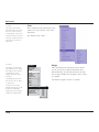
Menus and Submenus
Choosing Commands
As you proceed through the exercises, you will be directed to choose commands
contained in submenus of other menus, like the pull down menu. For example, you
1-1
User Guide Documentation
might be asked to select Define in the Color submenu of the Pen menu. That will be
written as Pen>Color>Define.
Tip:
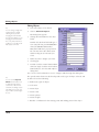
Margin Notes
Tips, referrals to other chapters, and alternative ways to
accomplish a task are displayed in the margin throughout the manual.
Graphite includes margin notes that provide information that may help you use
Graphite. There are three types of margin notes: Tips, Tech Notes and Referrals.
These notes have been given a special treatment so that you can instantly recognize
their significance and locate them for future reference.
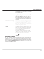
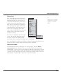
Tip
A tip provides instructions for getting the most out of Graphite. Tips may show you
how to speed up an operation or how to perform some timesaving drawing technique.
Tech Note
A technical note is intended to provide additional technical information, not necessary for using Graphite but useful in understanding how it works.
Referral
A referral directs you to related information contained somewhere else in the manual for the particular topic being addressed.
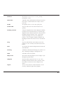
Style Conventions
This manual uses various style conventions which highlight certain terms or
phrases. The list below includes an explanation and an example in parentheses.
The conventions are as follows:
1-2
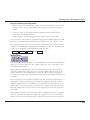
Bold
Tool palette names (Light palette); Tool name
(Single Line tool); Keyboard-entered text; Definition terms (as shown in these style conventions)
Italic
Terms used for the first time in a chapter; (Parametrics); Drafting Assistant notations (midpoint);
tool and dialog box options (Angle data field);
book references (User Guide); Message Line directions (Single Line:Pick the beginning point.); margin note headings (Tip); menu commands
(Extrude); filenames (Graphite.ini); stand alone
extensions (.dwg); directory names; drawing
names
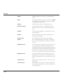
User Guide Chapter Breakdown
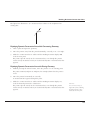
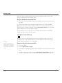
Bold and Italic
Command series (Pen>ColorDefine)
ALL CAPITALS
Key names on the keyboard (ENTER, RETURN)
Title Capitalization
Dialog box names (Edit Objects); menu names
(Pen menu); special Graphite phrases (the Drafting
Assistant)
all lower case
File names (Graphite.ini); stand-alone file extensions (.dwg)
User Guide Chapter Breakdown
The chapters are grouped into sections dealing with a specific area.
Sections
Referral:
1. Overview
Contains chapters that provide you with information on the documentation layout, basic elements
of Graphite and the Drafting Assistant.
2. Setting the Environment
Contains information on setting the drawing environment.
3. Creating Geometry
Contains information on creating geometry using
the tools of Graphite.
4. Editing
Contains information on using the tools and commands to edit your geometry.
5. Document Detailing
Contains information on adding text and dimensions to your drawing.
6. Viewing Your Designs
Contains information on viewing your geometry.
7. Documents
Contains information on opening, saving, importing and exporting files.
8. Parametrics and Symbols
Contains information on using parametrics and
placing symbols.
9. Geometric Analysis
Contains information on performing a 2D analysis
on your geometry.
Specific page information on
a particular tool or command can be found in the
index.
1-3
User Guide Documentation
Appendices
Operators and Units
Describes all operators and units which are
accepted by all Graphite data fields.
Special Characters
Lists all special characters not directly available
from the keyboard and symbols that you can use
in Graphite.
Creating Wireframe Models
Provides rules that will assist the 3D user in creating wireframe geometry.
DWG Notes
Provide notes to help the Windows user complete
a successful .dwg translation.
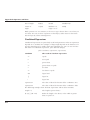
Program Settings & Files
Contains all of the default settings for Graphite following installation. It also includes a list of all the
folders and files that come with the program.
Other
Glossary
Defines terminology used in Computer Aided
Design and Drafting (CADD) and Graphite.
Task Index
Groups various tasks according to their functions
and the location in the manual.
Index
Lists features, tools and actions in Graphite and
their associated page number location in the manual.
Graphics
Most of the graphics in the manuals apply to both platforms of Graphite. In those
instances that require a platform and software reference, a Graphite Windows
graphic is used. When necessary, both Windows and Macintosh graphics will be
included.
1-4
User Guide Chapter Breakdown
On-Line Help
Graphite’s Help (Windows only) provides a complete description of the program’s
many features, commands, and tools. The Help index is organized by menus and
tools. In addition, context-sensitive Help is displayed when you highlight a command or tool and then press the F1 or the SHIFT+F1 key.
For information on installing Graphite, see the Readme text or Ashlar's web
page, www.ashlar-vellum.com.
1-5
User Guide Documentation
1-6
Graphite Overview
As mentioned in the Getting Started section of this manual, Graphite is a powerful
program that is quick to learn and use due to its technology. Graphite will help you
get your job done within your timeframe.
This chapter provides you with a brief overview of the following concepts:
• Wireframe Drafting
• The Model
• The Drafting Assistant
• The Design Process (including Drawing at Full Scale and Drawing Formats)
Wireframe Drafting
In Graphite you create wireframe models. A wireframe model consists of
the geometry that makes up the edges of the object.
A wireframe model can often be used in place of a prototype, so that simulations
and tests can be accomplished on the computer rather than in the laboratory. Models can be used for checking the visual specification, measuring distances between
points within the model and observing the visual and real intersections of lines.
3D wireframe models are most useful for pulling off multiple views and doing 2D
dimensioning and drafting on those views. This lets you do your design in 3D, and
then produce 2D working drawings from that 3D model.
2-1
Graphite Overview
Referral:
The definition of models is
also discussed in Chapter 13.
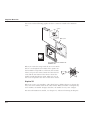
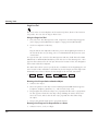
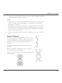
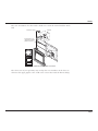
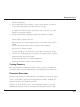
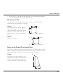
The Model
A Model exists in 3D space in the computer’s memory, whether the geometry is two
or three dimensional. A model is any combination of geometry, such as lines, arcs,
circles, dimensions, text, etc. Models are created in an infinitely large three-dimensional area. (In the following graphics each model has its own imaginary 3D model
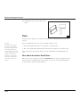
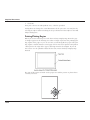
space). Models are not created directly on the sheet. What you see on the sheet is
only a projected view of the model.
A sheet in Graphite is an infinite 2D planar area (always aligned parallel to the
screen) that displays an image of one or more models. You view the model as if
looking through a camera while it moves around the model. The image of a model
is picked up by either a sheet camera or a detail view camera. The sheet camera
projects the image directly onto the sheet (called a Sheet View). The detail view
camera projects the image into a view window (called a Detail View) which rests on
the sheet. Sheets do not actually contain any geometry, only images of geometry.
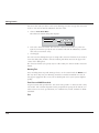
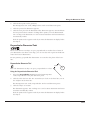
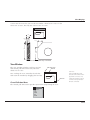
Your computer screen displays
all the views on the current
sheet. In the following graphic
you see a Top view of the model
picked up by the sheet camera
and projected onto the current
sheet. In the Top view the sheet
camera is aligned parallel to the
sheet.
y
Model
-z
t
Shee ra
came
odel
3D-M
x
e
spac
infinite 2D planar
area
cu
rre
nt
sh
ee
t
File
Ed
it
Layo
ut
Sel
ect
Arra
nge
: [Sh
ift =
Ext
end
ed,
Ctr
l=
Pen
Co
py,
Do
Text
ubl
e clic
k=
A
When you open a document,
you are looking down on top of
the x, y plane and you cannot
see anything in the z-direction,
which is coming toward you,
away from the screen.
2-2
All]
Ve
Dime llum
nsion
Un
title View
d1
s
3D
Op
tions
He
lp
Layer
.65
4789
.20
5987
-.235
6
Top
3D Top view
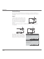
The Model
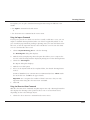
y
x
z
Graphite 3D Models
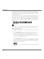
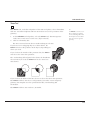
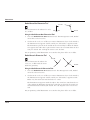
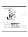
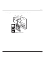
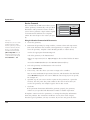
You must rotate the image to see what you are drawing in the z-direction.
The on-screen Trackball lets you rotate the sheet camera around the 3D model (this
changes your orientation, it does not rotate the model). The three-dimensional
object geometry (the model) stays fixed, even if you get the opposite impression on
2-3
Graphite Overview
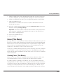
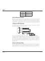
the screen. In the following graphic the sheet camera is rotated to the Trimetric
view.
Sh
cameet
era
y
3D Model
-z
odel
3D-M
e
spac
x
infinite 2D planar
area
cu
rre
nt
sh
ee
t
File
Ed
it
Sel
Layo
ut
ect
Arra
nge
: [Sh
ift =
Ext
end
ed,
Ctr
l=
Pen
Co
py,
Do
Text
ubl
e clic
k=
A
All]
Ve
Dime llum
nsion
Un
title View
d1
s
3D
Op
tions
He
lp
Layer
.65
4789
.20
5987
-.235
6
Trimetric
The Sheet camera is rotated to the
Trimetric view
When you rotate the image with the on-screen Trackball, it is as though the movement of the pointer on
the Trackball corresponds to a fulcrum; the location
where you press the mouse button becomes the fulcrum and the movement of the mouse rotates the
model around that fulcrum point. What you see on
the screen responds to the view of the sheet camera.
Graphite 3D
When you create view windows, either detail views, drafting layouts, or design layouts, each view window looks at the same model. When you make a change in any
view window, the model changes; therefore, the model in every view changes.
For more information on models, see Chapter 14, “Advanced Viewing Techniques.”
2-4
The Drafting Assistant
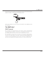
The Drafting Assistant
The Drafting Assistant is unique to Graphite and makes Graphite easy to use
because it thinks like a designer. The Drafting Assistant guides a designer in the creation of geometry. It displays temporary construction lines, provides information
about existing geometry, and gives notations of the relationship between new and
existing geometry in all three dimensions.
As you move the pointer near an existing geometric construction, the Drafting
Assistant’s snap point locks onto individual geometry, displaying an on notation.
The Drafting Assistant also displays information about geometric landmarks, such as
endpoints and centers, and temporary automatic construction lines, such as alignment and tangents.
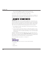
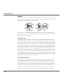
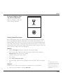
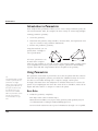
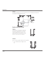
The following examples illustrate the alignment notations for the x, y and z axes.
align:z
The z-direction is perpendicular to the work plane.
align:z
on
align:x
The x-direction is parallel
to the work plane.
align:x
on
align:y
The y-direction is parallel
to the work plane.
align:y
on
For more information on the Drafting Assistant, see Chapter 4, “The Drafting Assistant.”
2-5
Graphite Overview
The Design Process
The computer revolutionized the design process. Graphite has contributed to this
by helping you quickly design a model that previously existed only in your mind's
eye.
Graphite
For Graphite 3D, depending on your needs, you can start your design in 2D and
continue on in 3D later or begin designing in 3D.
For example, you can choose to begin your design in the Trimetric view orientation
so that you see all three directions at once. You can also display other view windows with the Front, Right, and Top view orientations at quarter scale to observe
the construction from other angles. While you are drawing, you can zoom in and
out to enlarge and reduce areas as needed.
You can also rotate, move the origin, and change the work plane to take advantage
of the 3D modeling environment.
Drawing at Full Scale
In the paper world, you begin designing a model by deciding what scale to use so
that the model fits on a particular size sheet of paper. With Graphite, you postpone
scaling until after you have drawn the model at full scale. You can scale the geometry to fit on a standard drawing format provided by Graphite and then scale the
whole drawing to fit the size of paper you need.
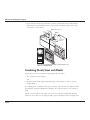
Constructing a 3D Model
You can use several different methods to create a model. The following steps are an
example of a process for a 3D model:
• Begin the construction by opening a new document.
• Set the preferences you prefer, such as the Pen Style, Grid, and selection modes.
For more information, see Chapter 5, “Basic Environment Setting.”
• Display the Triad symbol using the Show Triad command. This illustrates the
work plane orientation that acts as a point of reference when drawing in 3D.
• Display the Trackball.
• In the view menu of the Trackball, choose Trimetric. The sheet rotates so that
your construction is seen from the Trimetric view.
2-6
The Design Process
• Create the 3D model using the tool palette and Graphite commands.
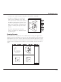
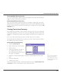
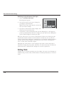
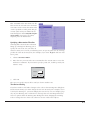
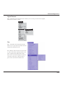
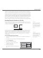
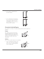
• To observe multiple view orientations
while you are modeling, choose Sheet
Into View from the Views menu, and then
specify the Views Design 4 layout. View
windows displaying the Top, Front, and
Right view orientations are displayed at
quarter scale along the right side of the
screen.
For more information on Sheet into
Views, see Chapter 14, “Advanced Viewing Techniques.”
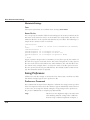
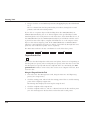
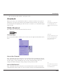
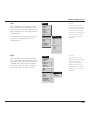
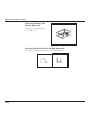
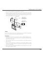
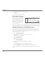
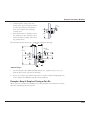
Drawing Formats
When the model is complete (or to be submitted for review), you might want a
drafting version incorporating several views on a drawing format with dimensions
and annotation. To create; import a drawing format and make adjustments to the
views as necessary (or use a premade layout with format in Sheet Into View). This
example shows a premade layout with four views (available only for the 3D version).
Vellum
2-7
Graphite Overview
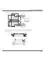
• Flatten any view that contains geometry you want to edit independently. For
more information on flattening a view, see Chapter 14, “Advanced Viewing Techniques.”
• Crosshatch, dimension, annotate, and perform any view editing you need.
• Fine-tune the model if necessary.
• Specify the paper size from the Print Setup (Windows) or Page Setup (Macintosh)
command in the File menu.
• Set the scale for the drawing format to fit on the plotter paper. If you don’t care
about the exact scale, you can click Fit in the Drawing Size dialog box and the
geometry and format will be scaled appropriately for the paper size you have
specified.
• Plot the finished drawing. For more information on plotting, printing and related
activities, see Chapter 15, “Graphite Documents.”
2-8
The Basics
This chapter describes the basic components of Graphite. This brief overview of
useful features may be all you need to know if you are familiar with CAD software.
The following topics are covered:
• Using a Mouse
• Parts of the Graphite Window
• Menu Bar, including the dialog boxes
• Preferences
For more information about standard elements such as menus, scroll bars, File
menu commands, and dialog boxes, refer to the Windows or Macintosh User’s
Guide that came with your computer.
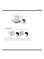
Using a Mouse
The mouse is your communication device; you use it to tell the computer what you
want to do. Use the mouse to indicate locations, choose commands, select tools,
and construct objects.
Tips:
If your mouse has more than one button, you can use the right button to popup a
menu that contains a variety of commands and functions. By default the right
mouse button provides shortcuts to the most popularly used commands.
To set up the right mouse button options, right click in the drawing area to activate
the menu. Choose RightMouse. When the dialog box appears, check the boxes to
activate or deactivate items you want displayed in the popup menu.
Windows only: If you are lefthanded and your mouse has
more than one button, you
can change the functionality
to the right mouse button.
You make this change in the
Control Panel of Windows.
3-1
The Basics
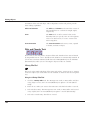
This manual uses the following terms for mouse activities:
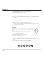
Pointer
An arrow or any other graphic symbol that allows
selection or creation of an object. Move the pointer
to point to a command or an object on the screen.
Depending on its location, the pointer is an arrow
or looks like the current tool.
Arrow Pointer Selection Arrow Center-Point Circle
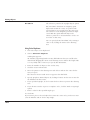
To move the pointer, move the mouse on the
mouse pad. You use several different mouse
actions with Graphite.
3-2
Point
Move the mouse until the pointer is over the item
you want.
Press
Press and hold down the mouse button.
Click
Quickly press and release the mouse button once.
Double-click
Click the mouse button twice, quickly in succession.
Drag
Press and hold down the mouse button, move the
mouse, then release the mouse button.
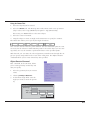
Parts of the Graphite Window
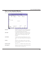
Parts of the Graphite Window
When you start Graphite, the following window appears.
Title Bar
Includes the title of the active document and buttons for controlling the window including boxes
for zooming and closing the program.
Menu Bar
Contains the Graphite menus of commands and
settings. You can make choices from the menus
with the mouse or by using special key combinations.
Tool Palette
Contains the drawing and editing tool icons you
use for constructing, editing and annotating geometry.
Pointer
Shows the active position on the screen. If the
pointer is in the drawing area, its shape represents
the current tool.
Pointer Locator
Shows the x, y coordinates of the pointer location.
Message Line
Displays the name of the current tool and step-bystep instructions for using the tool.
3-3
The Basics
Drawing Area
Consists of multiple layers where you construct
and annotate geometry.
Status Line
Shows the coordinate location and other geometric
parameters of the current construction.
Scroll Bars
Allow you to move around a drawing so you can
see different sections of it through the Graphite
window. The scroll buttons allow you to move one
line at a time.
Work Layer Indicator
Displays the name of the current layer and provides a menu for changing the work layer.
Title Bar
The Title Bar includes the name of the current document, and the Control Menu,
Minimize and Maximize/Restore buttons (Windows) or the Close and Zoom boxes
(Macintosh).
Windows
Close Button
Maximize Button
Minimize Button
Control Menu Button
Control Menu Button
Allows you to close, move, and change the size of
the window. This button is available on all windows and many dialog boxes.
Double-clicking this button closes the window
without displaying the menu. If you want to
choose a different option from the Control menu,
click the button once to display the menu and then
make your choice.
Minimize Button
3-4
Reduces the Graphite window to an icon near the
lower-left corner of the screen. This action does
not close or save the document, it only shrinks the
window to an icon so you can perform some other
Windows-related task. To redisplay the window,
double-click the icon.
Parts of the Graphite Window
Maximize/Restore
Displays the window, full or partial screen. Once
the window appears full screen, click the button
again to restore it to its previous size.
Macintosh
Zoom Box
Close Box
Close Box
Closes the window when you click on it. If you
attempt to close the window without saving your
work, Graphite displays a message so you can
decide whether to save or not.
Zoom Box
Toggles the window size between the previous
size and full size.
Tool Palette
A tool palette is a group of tool icons along the left side of the screen. The icons
represent the tools for drawing, editing, and annotating geometry.
Selecting a Tool from the Tool Palette
1.
Position the arrow pointer on the icon of the tool you want to use.
2.
Click the mouse button.
The icon appears highlighted to indicate its selection. The Single Line
tool is selected here.
3-5
The Basics
Tool Subpalettes
Most of the tools in the tool palette contain a subpalette of tools with related functions. The (arrow) in the lower-right corner of the tool icon represents the presence
of a subpalette which contains related tools.
Viewing and selecting from a subpalette are similar to choosing a command from a
menu.§
Selecting a Tool from a Subpalette
1.
Position the arrow pointer on the tool.
2.
Press the mouse button.
The subpalette appears to the right of the tool.
3.
Drag the pointer to highlight the desired
tool.
4.
Release the mouse button.
The selected tool replaces the previous tool in the
tool palette. The highlighted icon in the tool palette
shows that your selection from the subpalette is the
active or current tool.
The new tool is visible in the tool palette until you select another tool from the
same subpalette. The tools in the subpalette remain in the same order; only the tool
displayed on the tool palette changes.
Once you select a tool, additional information appears to help with your construction. The Pointer, Pointer Locator, Message Line, and Status Line all provide feedback about the active tool.
If you want to select a tool that is already displayed in the tool palette, you only
need to click it; you don’t need to select it from the subpalette.
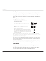
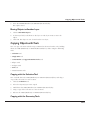
Smart Pointer
When you select a tool and move the pointer into the drawing area, the pointer
shape represents the selected tool.
Some of the pointers, like the single line pointer, are simple cross-hairs. Others,
such as the Opposite-Point Circle pointer, resemble the tool itself.
3-6
Parts of the Graphite Window
The pointer, called a smart pointer, displays indicators for multi-step procedures.
Each smart pointer has a dot, the hot spot, showing the next point you should specify. The dot changes position on the pointer during each step of the construction.
Hot Spot
The smart pointer shows you where to click next.
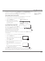
For example, the Opposite-Point Circle pointer illustrated above shows that the first
click of the mouse places a point on one edge of the circle you’re creating. After
you click a location, the hot spot moves to the other side of the pointer, showing
that the next click places a point on the opposite edge of the circle. (See the
graphic below).
Your first click
The hot spot moves to the other side of the
smart pointer to indicate the next step.
After you click the second location, the
circle appears. The hot spot moves back
to its original position on the pointer so
that you can create another circle.
Tech Note:
The number of decimal
places displayed in the locator
field is determined by the Precision setting in the Units dialog box (choose
Layout>Preferences>
Units).
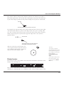
Pointer Locator
The Pointer Locator is two numbers to the left of the horizontal scroll buttons at the
bottom of the drawing area.
X 1.53
Layer1
Z 0
Y 1
2.4
-1.87
dX .87
dY .87
dZ 0
The location indicator tracks
the pointer position of any
tool other than the Selection tool.
L 1.22
0
This locator continuously tracks the pointer location when the pointer is in the
drawing area, displaying the X,Y coordinates of the current location relative to the
3-7
The Basics
origin. The origin (0,0,0) is in the center of the screen when you open a new document. When you make the grid visible by choosing Layout>Show Grid, a symbol
appears at the origin (0,0).
Message Line
The Message Line across the top of the drawing area provides concise instructions
for the use of the selected tool.
For example, after selecting the Center-Point Circle tool, the Message Line appears
as illustrated below:
Center-Point Circle: Pick center. [Ctrl = Copy previous]
The instructions in the Message Line for some tools also indicate optional activities.
For example, if you hold down the CTRL (Windows) or OPTION (Macintosh) key
while using the Center-Point Circle tool, the next mouse click creates a copy of
the last circle with the center placed where you clicked.
Status Line
The Status Line provides measurements, angles, X,Y coordinates and delta values
for the current construction. The current tool determines the number of status data
fields and which of the status data fields is highlighted after the construction. For
example, if you select the Center-Point Circle tool, the Status Line shows the X,Y
coordinates for the center of the circle and the length of the diameter.
When you click the last point of the circle, the diameter (D) data field highlights in
the Status Line to indicate that it is active. It shows the diameter of the circle you
just created. If you type a new number, and press the ENTER (Windows) or
RETURN (Macintosh) key, the diameter of the circle updates reflecting the change.
Tip:
You can also change objects
with the Edit Objects command.
3-8
You can change any or all entries in the Status Line, but when you press ENTER
(Windows) or RETURN (Macintosh), you can’t make any more changes in the Status
Line.
Parts of the Graphite Window
The number of decimal places displayed in the status data fields is determined by
the Precision setting in the Units dialog box (choose Layout>Preferences>Units).
Moving Between Status Data Fields
Use the TAB key to move to the right, highlighting the next field. When you press
ENTER (Windows) or RETURN (Macintosh), the construction redraws according to
the new specifications in the Status Line. You can also use your mouse to activate a
Status Line data field.
You can use the Status Line arrows to scroll if any of the status data fields are off
screen.
Drawing Area
You use the drawing area for all construction, editing, and annotation of geometry.
Think of the drawing area as a sheet of paper of unlimited size that you use to construct full-size unscaled drawings. You use the scroll bars to move the sheet so the
portion you want to work on is visible in the window.
Displaying the Grid
Tip:
If you wish to work with a grid in the
drawing area, choose Layout>Show Grid.
When the grid is visible, constructions
snap to the grid, meaning that any geometry point that you click snaps onto the
closest grid point. The coordinate symbol
appears at the origin when the grid is visible.
Normally, you do not need
to display the Grid, since the
Drafting Assistant offers a
more elegant support than
the grid.
0,0 Origin
Coordinate Symbol
Scroll Bars
The scroll bars allow you to move the sheet up and down or right and left. You can
display different parts of the drawing sheet by dragging the slider of a scroll bar to
the approximate location. For example, the right, center, or left position in the hor-
3-9
The Basics
izontal scroll bar displays the right side, middle, or left side of the drawing, respectively.
You can also click the arrows at the end of the scroll bars to move the sheet one
line at a time. If you click in the scroll bar, the sheet moves one window at a time.
Work Layer Indicator
The work layer indicator in the lower-left corner of the screen shows which layer is
the current work layer. New geometry goes on the work layer. If you want your
construction to go on a layer, first make it the current layer.
To select a work layer, position the pointer over the work
layer indicator, then press the mouse button. All available
layers are then displayed in a pull-down menu from which
you can select a different layer to be the current work layer.
X 1.53
Y
Layer1
-1.87
2.4
Construction
dimension
Layer1
Drag to the layer and release the mouse button. The selected layer becomes the
work layer and all geometry you create will be placed onto that layer.
Menu Bar
The Graphite menus contain related commands and settings.
3-10
File
Commands that affect entire documents (files).
Edit
Commands to select and manipulate objects.
Layout
Commands and settings that specify the drawing
area and provide program features and functionality, such as construction lines and 2D analysis.
Arrange
Commands for zooming (to change the area displayed in the window) and setting specifications
for objects.
Menu Bar
Pen
Commands to specify pen characteristics (style,
color, weight, and pattern), crosshatching, fill and
arrows.
Text
Commands to set the font, size, style, alignment,
and indentation of text and also to create text
blocks and forms (title blocks).
Dimension
Commands that specify dimensions and their format and tolerance.
Views
Commands to control multi-page documents,
including Perspective on/off, Perspective Edit and
View Mode. The menu also contains Define View,
View the Plane, Unfold View, Flatten View and
Show Trackball.
Utilities
Commands to create and invoke macros.
Displaying a Graphite Menu
1.
Point to the menu name.
2.
Click on the name.
The menu appears. If you want to dismiss the menu
without making a choice, click outside the menu.
Choosing a Command from a Menu
1.
Point to the menu name.
2.
Click on the name.
The menu appears.
3.
Click on the command.
The command executes, or the setting, such as Selectable Points, toggles on or off.
Mouse versus Keyboard
Graphite’s menu items can be chosen with the mouse or with a combination of
keys on the keyboard. For example, you can use various methods for displaying the
Edit menu.
3-11
The Basics
Windows and Macintosh:
• Click on Edit in the menu bar.
Windows only:
• Press the ALT key and then type E.
• Press the ALT key and then press the RIGHT ARROW key until Edit is highlighted
in the menu bar; then press ENTER.
You also have various methods for choosing commands with the keyboard. For
example, you can use any of the following methods to choose Layout>Show Grid.
Windows:
• Press ALT and L and then type G.
• Press ALT and then use the RIGHT ARROW key to highlight Layout and press
ENTER. Then press the DOWN ARROW key to move the highlighted area to
Show Grid and press ENTER.
• Hold down the CTRL key and type G.
The first method is the mnemonic method. Press the ALT key with the appropriate letters for the menu and command as indicated by the underlined character in
the names.
Macintosh:
• Hold down the z (command) key and type G.
The third method for Windows and the only one available for Macintosh is a keyboard accelerator. When available it is denoted by the key sequence listed on the
menu.
While keyboard functionality is always available, this manual generally describes
making choices with the mouse.
3-12
Menu Bar
Submenus
Commands followed by an (arrow)
symbol have submenus which display when the command is highlighted.
1.
Pull down the menu.
2.
Click on a command followed by
an (arrow) symbol.
The submenu displays.
3.
Click on the submenu.
4.
Click the desired command.
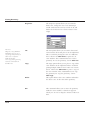
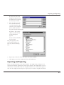
Dialog Boxes
When you choose a command followed by an
ellipsis (…), such as Edit Objects in the Edit
menu, a dialog box appears.
Dialog boxes allow you to qualify the command
you chose by adding information. For example,
in the Edit Objects dialog box above, you can
change the specifications of the selected object.
If a dialog box obscures your view of the drawing area, you can move it to a new location by
dragging it with the pointer on the Title bar.
3-13
The Basics
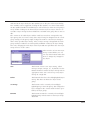
Option Buttons
Option buttons indicate mutually exclusive choices; you can select only one option
at a time. Click the option you want and the button turns black, as shown by the
inches option below.
Units
Precision:
Selected Option
Option Buttons
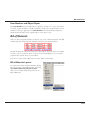
Check Boxes
inches
mm
feet
cm
feet/inches
meters
Leading 0’s
Trailing 0’s
Cancel
OK
Check Boxes
Check boxes, as shown above, provide options you can switch on and off and
which are not mutually exclusive. A (check mark) shows the options is set.
List/Entry Boxes
Tip:
Windows: You can also hold
down the ALT key and type a
letter to select the first item
that begins with that letter,
then use the arrow keys to
move to the selection you
want. Once your choice is
highlighted, press ENTER.
Some dialog boxes contain lists of options, displaying an arrow to provide access to the list.
If the entry includes an arrow you can display a
menu which works like a submenu on the menu
bar but the item you specify appears in the box
once you select it.
Some list boxes also allow you to type an entry.
For example, you can type a value in the Scale
data field in the Drawing Size dialog box or
choose from the pop-up menu. See the graphic
below.
Drawing Scale
1:1
To type an entry, select the current entry (if it isn’t already selected), then type a
new entry. In most cases, clicking on the OK button, saves the changes.
3-14
Preferences
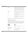
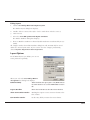
Asterisks
When an item in the dialog box displays an asterisk (*),
you can specify a value by clicking or dragging in the
drawing area. This feature is particularly useful for specifying location because you don’t need to know any x, y
coordinates.
Apply Buttons
Some dialog boxes have an Apply button that
allows you to apply the specification you just
set. You can leave the dialog box open to set
other specifications.
For example, once you crosshatch a part, you
can leave the Crosshatch dialog box open and
select other objects to be crosshatched.
Closing a Dialog Box
If a dialog box contains an OK or Cancel button or an action button such as Open,
the dialog box closes when you click the button. Otherwise, you dismiss the dialog
box manually by double-clicking the Control Menu (Windows) or clicking the Close
Box (Macintosh) button in the upper-left corner of the box. If the dialog box has an
Apply button, such as the Crosshatch dialog box above, you must dismiss it manually.
Toggling Commands
Commands that set a condition (such as Selectable Points and Arrow At Start) display a check mark (check mark) in the menu to indicate that they are active. To
turn a command off, choose it and the check mark disappears.
In the case of pen styles and text characteristics, the check shows the current setting.
Other commands, Show Grid, Show Points, Show Palette, Show Trackball and Show
Triad toggle to Hide (Grid, Points, Palette, Trackball or Triad) when the component
is visible.
Preferences
All files are saved with their settings when you choose File>Save. The characteristics used for new files (the default settings) are contained in the preferences file.
3-15
The Basics
The preferences filename is prefs.vc6 (Windows) or Graphite prefs (Macintosh).
You can change the default settings so that every new document opens with the
settings you want. The following specifications can be set in the preferences file:
• Pen styles
• Text characteristics
• Preferences settings (snap, grid, units, selection color indicator, visualization, palette status and palette location)
• Grid display
• Layer and sheet specifications
• Work Layer
• Dimension and tolerance formats
• Arrowhead type and display
• Drawing size and scale
• Zoom scale
• Fillet radius
• Chamfer angle and length
• Resolve values
The default value of any setting that can be changed on a menu or in a dialog box
can be set in the preferences file.
Changing the Default Settings Manually
1.
Open the preferences file (it’s in the same folder as the Graphite application).
2.
Change the characteristics you want and, if needed, create the layers and sheets
you want.
3.
Save and close the file.
The file must be stored in the same folder as the Graphite application.
The preferences are set for subsequent new documents.
The settings will not take effect until the next time you launch Graphite.
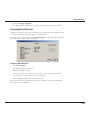
Changing the Default Settings with Save Preferences
1.
3-16
Open a new Graphite file.
Preferences
2.
Set the preferences as you want them.
3.
Choose Layout>Preferences>Save Preferences.
The preferences are set for this file. The settings for future files take effect the next
time you launch Graphite.
Important: It is advisable to use Save Preferences only before you start drawing.
Otherwise, you may be saving data that you do not want in new files. For example,
if you choose Save Preferences on a file with a detail view and multiple models, all
new files will contain a detail view window and multiple models.
3-17
The Basics
3-18
The Drafting Assistant
The patented Drafting Assistant is the feature that makes Graphite unique among
design and drafting software products. The Drafting Assistant thinks like a drafter; it
automatically knows where you typically want construction lines and displays them
temporarily when you need them.
The Drafting Assistant also makes it easy to select existing points for construction
by displaying information about the pointer’s location in the drawing area. If a
Drafting Assistant notation displays when you click, the construction snaps onto the
geometry precisely, without requiring finely tuned eye-hand coordination or
tedious selection of special modifiers, modes, or other specialized construction
tools.
The following topics are covered in this chapter:
• Snapping onto Geometry
• Drafting Assistant Construction Lines
• Permanent Construction Lines
Snapping onto Geometry
When the pointer is in the drawing area, it has a snap point function. The snap
point locks onto specific points on existing objects as you move the pointer near
them.
4-1
The Drafting Assistant
The Drafting Assistant tells you when the snap point is on an object.
on
The Drafting Assistant snapping onto a circle
The Drafting Assistant displays information about the location of the snap point.
This information appears either beside the pointer or next to the object itself.
tangent
The Drafting Assistant displaying the relationship
between the circle and the line that is being constructed.
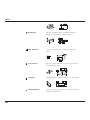
The Drafting Assistant tells you when the snap point has locked onto the points of
an object.
center
center
The center of an arc or circle. Move the pointer
across the arc or circle to display on for the arc
or circle, then move the pointer near the center to
display the center point notation.
endpoint
endpoint
The endpoint of lines, arcs, circles, ellipses
and splines.
4-2
Snapping onto Geometry
midpoint
midpoint
The midpoint of lines, arcs, circles, ellipses
and splines.
intersection
intersection
The intersection of two lines (permanent lines and
the Drafting Assistant’s dynamic construction lines)
or curves.
quadrant
quadrant
Quadrant points on an arc or circle displayed at
3 o’clock, 6 o’clock, 9 o’clock and 12 o’clock.
vertex
vertex
The vertices of an ellipse, spline, or dimension
point.
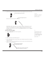
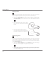
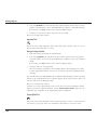
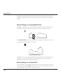
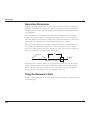
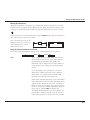
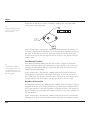
Using Tangents and Perpendiculars
If you click a point on an arc or circle and drag the pointer away at about a 45º
angle, the Drafting Assistant locks onto the tangent. If you drag away at a 90º angle
the Drafting Assistant locks onto a perpendicular.
tangent
Tangent
perpendicular
Perpendicular
4-3
The Drafting Assistant
If you continue holding down the mouse button, the line remains tangent or perpendicular while you drag the ending point around the object.
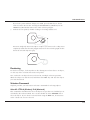
This is a useful feature if, for example, you want to create a line from
and tangent to an existing circle to
the tangent point of another circle.
Once a line is tangent to the circle, it can be
dragged to the tangent point on the other circle,
with the tangency maintained at both ends.
tangent
tangent
The Drafting Assistant locks onto a tangent or
perpendicular only when the Drafting Assistant
starts from the on notation. You cannot begin
from a specific point, such as endpoint, quadrant or vertex.
Tech Note:
Another way to create geometry from an exact location
relative to another object is
to reduce the Hit Radius of
the Drafting Assistant with a
lower number of pixels or to
zoom in on the drawing to
separate the construction
points visually.
tangent
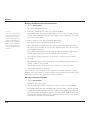
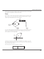
Keyboard Snap Points
You can direct the Drafting Assistant to snap onto an object. For example, you may
want to start a new line from the exact center of a circle. If you hold down the
mouse button and press the c key on your keyboard, the Drafting Assistant finds
the center of the circle when you move the pointer near the center.
Using the Drafting Assistant for Snapping onto Geometry
The following table lists the keys for finding specific points. The desired point must
be within the Hit Radius (defined later in this chapter) of the pointer. Press the
mouse button first and then press one of the following keys on the keyboard.
Keyboard snap points only work when there are multiple snap points within the Hit
Radius of the pointer.
4-4
Letter
Snaps To (Align)
c
center
e
endpoint
g
grid
i
intersection
m
midpoint
Snapping onto Geometry
n
no point
o
on
p
perpendicular
q
quadrant
t
tangent
v
vertex
%
the percentage point set in the Snap dialog box
Pressing the SPACEBAR or clicking the mouse releases all snap restrictions.
Keyboard snap points act as a filter. For example, if you want to place the end of a
line at the center of a circle but the intersection of two other objects lies near the
center (within the specified Hit Radius), the Drafting Assistant will not know which
point—the center or the intersection—to snap to. By pressing the c on the keyboard while dragging the line, the Drafting Assistant knows to snap to center and to
disregard the intersection (or any other snap point that falls within the Hit Radius).
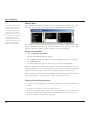
DAssistant Command
This command, found in Layout>Preferences, turns the Drafting Assistant on or
off. When the Drafting Assistant is not
checked in the menu, the Drafting Assistant is off.
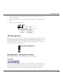
Snap Basic Command
This Snap command, found in Layout>Preferences, sets specifications for the
Drafting Assistant. This command should be distinguished from the Snap command,
4-5
The Drafting Assistant
chosen through the Utilities menu, that allows you to activate snap modes of the
Drafting Assistant.
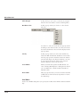
Snap
Hit Radius: 12
Alignment Angles: 0°; 90°
pixels
Additional Creation Angles: 45°; -45°
% Point:
Cancel
Hit Radius
OK
This setting determines the detection distance in
pixels. When the pointer is within the specified Hit
Radius, the Drafting Assistant notations are displayed and the object is selected when you click
the mouse. The default Hit Radius is 12 pixels.
If you can’t specify locations that are close together
because the Drafting Assistant snaps to an existing
control point, you can do any of the following:
• Decrease the Hit Radius.
• Zoom in so more pixels separate the existing
point and the point you want to select.
• Lock on a point by pressing the mouse button
and then typing the letter that represents the
point (m for midpoint, for example).
If you set the Hit Radius to zero, you disable
the single click selection of the Selection tool
(dragging a selection fence and double-clicking to
select all objects will still work). Instead, you might
consider using the Selection Mask in the Edit menu
to specify that some objects cannot be selected.
Alignment Angles
4-6
These angles define the dynamic construction lines
that the Drafting Assistant automatically uses. If
you want to change the orientation of your drawing, you can change these specifications.
For example, you could set these angles to 30°, 90°
and 150° for an isometric drawing. The defaults are
Snapping onto Geometry
0° (horizontal) and 90° (vertical). Use a semicolon
to separate the values.
To display a temporary construction line through
a point, move the pointer to the point to activate
it (a diamond appears); construction lines automatically display through the active point. You can
have as many as eight active points. When you
activate the ninth point, the first one in the series
deactivates.
Additional Creation Angles
These lines are used by the Drafting Assistant only
when you are creating geometry and they are not
part of the list of lines generated from the eight
active points. The defaults are 45° and -45°. Use a
semicolon to separate the values.
% Point
The divisions of a line for Drafting Assistant notations. If you want to divide the line into quarters,
use a 25 specification. The default is 50, which
shows the midpoint of lines.
For example, entering 25 instructs the Drafting
Assistant to tell you when the pointer is 25% of
the distance along a line as shown below.
%point
Snap Mode Command
This Snap command is automatically available when you first start Graphite. This
command allows you to activate and deactivate the different snaps modes of the
Drafting Assistant. This command should be distinguished from the Snap command,
chosen through the Layout>Preferences menu, that allows you to set basic specifications of the Drafting Assistant.
4-7
The Drafting Assistant
Choosing this item displays the following dialog box:
All snap modes are activated by default. When you want to
deactivate a snap mode you click the related check box.
Drafting Assistant Construction Lines
In addition to snapping onto geometry, the Drafting Assistant also displays dynamic
construction lines. The three types of construction lines you use most frequently—
vertical, horizontal and 45° angle lines—display automatically during construction.
These construction lines appear temporarily to help you align geometry. Once
you’ve set a point, the Drafting Assistant construction line disappears—your drawing is not cluttered with extraneous lines.
Dynamic construction lines extend automatically from the last point you created.
You may want to activate other points so the Drafting Assistant displays construction lines relative to them. Simply move the pointer over the geometry to activate or
“wake-up” its control points, then move away horizontally or vertically.
Of course, you also have the option of creating permanent construction lines and
other shapes, as described later in this chapter.
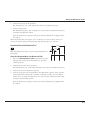
Using the Drafting Assistant’s Construction Lines
After you have indicated the first endpoint of a line, and you move the pointer horizontally, vertically, or in a 45° direction, the dynamic construction lines appear.
4-8
Drafting Assistant Construction Lines
The figure here illustrates a 45° construction line relative to the endpoint of an
existing line.
on
align:45°
Displaying Dynamic Construction Lines while Constructing Geometry
1.
Click a point to begin new geometry.
2.
Move the pointer away from the point horizontally, vertically, or at a 45° angle.
3.
While the construction line is visible and the Drafting Assistant displays on,
click the next point.
The point is placed exactly on the construction line, even though the pointer
wasn’t exactly on that line when you clicked. The dynamic construction line disappears.
Displaying Dynamic Construction Lines with Existing Geometry
1.
Without pressing the mouse button, move the pointer over an existing point.
The point notation (endpoint or midpoint, for example) shows that the point is
active.
2.
Move the pointer horizontally or vertically.
A construction line appears through the point.
3.
While the construction line is visible and the Drafting Assistant displays on,
click the desired point in the construction.
The point is placed exactly on the construction line, even though the pointer
wasn’t exactly on that line when you clicked. The dynamic construction line disappears.
Tech Note:
You can have as many as
eight active points; activating
the ninth point in a series
deactivates the first point.
4-9
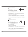
The Drafting Assistant
The figure here illustrates intersecting construction lines drawn
through two existing,
active points.
perpendicular
Once you’re familiar
with the Drafting Assistant, you’ll see how
Graphite streamlines
design and drafting
tasks!
align
intersect
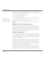
Setting New Drafting Assistant Construction Angles
You can add to or change the angles that the Drafting Assistant uses for dynamic
construction lines by choosing Layout>Preferences>Snap. Enter the construction
line angles, separated by semicolons, in the appropriate data field.
Permanent Construction Lines
Referral:
More information on Layers
can be found in Chapter 13,
“Viewing Geometry.”
In addition to the Drafting Assistant’s dynamic construction lines, you may want to
create construction lines that remain displayed until you hide or remove them.
There are two methods for creating permanent construction lines: strokes and the
Construction command (in the Layout menu). Construction lines automatically
appear on the construction layer, not the work layer of your drawing. You can hide
the construction layer to view or print the drawing without construction lines.
When you want to get rid of all construction lines, choose Layout>Delete Constructions. (Everything on the construction layer deletes, regardless of the object's
pen style).
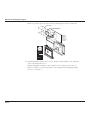
Stroke Construction Lines
Stroke construction lines are lines that you create with the mouse. Hold down the
CTRL+SHIFT keys (Windows) or the key (Macintosh) and drag the mouse horizontally or vertically. Since you are working in the drawing area, the Drafting Assistant helps you place the stroke precisely.
4-10
Permanent Construction Lines
Holding down the CTRL+SHIFT keys (Windows) or the key (Macintosh) changes
the mouse pointer to the Stroke point ().
Drag the pointer
horizontally or vertically
center
Tip:
Drag
Result
Vertically
A vertical construction line through the first point
of the stroke.
Horizontally
A horizontal construction line through the first
point of the stroke.
You can use strokes to create
construction lines while you
are in the process of using a
tool.
Using Stroke Construction Lines
Construction lines are as long as the dimensions of the viewing area of the screen
or the plot region (as designated in Drawing Size dialog box in the Layout menu),
whichever is larger.
For example, if you are using the Connected Lines tool, you can create a construction line that extends through the center of a circle:
1.
Hold down the CTRL+SHIFT keys (Windows) or the
pointer becomes the Stroke pointer ().
2.
Move the pointer near the center of the circle.
key (Macintosh). The
The Drafting Assistant snaps onto the center point.
3.
Drag the mouse vertically or horizontally away from the midpoint.
The construction line appears through the center and you are still in the process of
creating connected lines after releasing the CTRL+SHIFT keys (Windows) or the key (Macintosh).
The Construction Command
Stroke construction lines are useful for creating lines through existing points. If you
want to create a construction line at a location other than an existing point or at a
particular angle, you can use the Construction command.
4-11
The Drafting Assistant
Tech Note:
Using the Command CTRL+K (Windows) +K (Macintosh)
Graphite automatically places
construction lines on the construction layer. When you
choose Layout>Delete
Constructions, everything
on the construction layer is
deleted, regardless of the
object’s pen style.
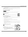
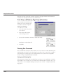
This command in the Layout menu creates a construction
line on the construction layer of the current document.
You can specify the angle of the construction line or the
offset from a reference point defined by the X, Y coordinates. The asterisk shows that the values can be specified
by clicking or dragging the mouse; values can also be
typed into the data fields.
The distance dragged will always be entered in the Offset data field as a positive
value, regardless of the direction dragged.
Specifying the Construction Line Angle with the Mouse
1.
Click the Angle data field.
2.
Drag a vector in the drawing area.
The angle of the vector line appears in the Angle data field.
Specifying the Construction Line Offset with the Mouse
1.
Click the Offset data field.
2.
Drag the offset distance in the drawing area.
The distance you drag appears in the Offset data field. Be aware that the offset is
determined by the angle of the construction line as shown.
90°
+
+
45°
- +
0°
-
Specifying X,Y Coordinates with the Mouse
Tip:
Windows: You can also type a
letter to select the first item
that begins with that letter,
then use the arrow keys to
move to the selection you
want. Once your choice highlights, press ENTER.
4-12
The coordinates of the last point you specified appear in the X and Y data fields,
but you can change them by doing the following:
1.
Click the X data field.
2.
Enter new coordinates.
or
In the drawing area, click the location of the point through which the construction
line should pass. The coordinates are entered automatically for both the X and Y
data fields.
Permanent Construction Lines
Creating Multiple Construction Lines
You can create multiple construction lines through the same point by entering the
angles you want separated by semicolons.
Creating Parallel Construction Lines
You can create parallel construction lines by specifying a single angle value with
different offsets separated by semicolons. You can also create parallel lines by creating one construction line using this data field, then creating new lines with the Parallel Lines tool.
Creating Construction Geometry
Non-construction geometry is placed on the work layer. You can create temporary
construction geometry, such as arcs or circles, by making the construction layer the
work layer, creating the geometry and switching to another layer to continue your
work.
You can use the Construction pen style if you like, but it’s not essential.
Lines made with the Construction pen do not go on the construction layer unless
you make that layer the work layer.
Creating Construction Geometry
1.
Choose Layout>Layers.
2.
Click Construction in the list box.
3.
Click Set Layer.
4.
Create the geometry you will use
for construction. You can use
the Construction pen style, but any
pen style is acceptable.
5.
When the construction geometry is complete, make another layer the work
layer.
6.
Close the dialog box.
7.
Continue your work.
Tip:
You can select construction
lines in the usual manner
from any layer; the construction layer doesn’t have to be
the work layer.
Once you no longer need the construction geometry, choose Layout>Delete Constructions to remove all geometry on the construction layer.
4-13
The Drafting Assistant
Removing Construction Lines
If you have many construction lines and you want to delete only one or two of
them, select the lines you want to remove, and then choose Edit>Delete or press
the BACKSPACE (Windows) or DELETE (Macintosh) key. You can remove all the
construction lines that you’ve created by choosing Layout>Delete Constructions.
Delete Constructions
This command in the Layout menu deletes all construction lines and any geometry
on the construction layer. The Drafting Assistant’s dynamic construction lines
appear only temporarily and are not affected by this command. Any geometry on
the construction layer (regardless of the pen style used) is deleted by this command.
You can retrieve deleted construction geometry within the eight (8) level limit of the
Undo command.
4-14
Basic Environment Settings
This chapter describes the options you have for adapting Graphite to your needs.
The following topics are covered:
• Pen Styles
• Pen Characteristics, including the color palette
• Setting Units
• The Grid
• Drawing at Full Scale
• The Drafting Process
• OS Settings
• Saving Preferences
• Saving Palettes
Pen Styles
The pen style determines the appearance of lines on the screen and during plotting.
If you are using a monochrome monitor or printer, all lines will be black but the
weight and pattern will be visible. Any line thickness of less than .016 inch appears
one pixel wide on the screen. When you print or plot such lines, you can see the
different weights.
5-1
Basic Environment Settings
The default pen style is Outline—solid, black lines, .01 inch wide. You can change
to a different pen style or change an individual characteristic of the current pen.
You can choose from nine different pen styles in the Pen menu. The characteristics
are listed below.
Pen
Pattern
Weight
Color
Outline
Solid
0.010
Black
Visible
Solid
0.020
Black
Hidden
Hidden
0.016
Red
Dash
Dashed
0.016
Yellow
Center
Center
0.010
Green
Pen
Pattern
Weight
Color
Phantom
Phantom
0.010
Cyan
Dimension
Solid
0.002
Blue
Balloon
Solid
0.005
Green
Construction
Dotted
0.002
Magenta
When you want to change pens, you have three options: choose a different pen
style from the Style submenu in the Pen menu; choose different characteristics for
the current pen from the pen characteristics listed in the Pen menu, (Color, Weight
and Pattern); or use the Edit Style command in the Style submenu to permanently
alter the characteristic of the pen. The current pen style is checked in the Style submenu.
5-2
Pen Characteristics
Changing the Pen Characteristics of an Object
1.
Select the object.
2.
Choose Pen>Style and select the pen style you want to change the characteristics of the selected object. If you only want to change one characteristic rather
than the entire pen style, choose the characteristic from the pen characteristics
listed in the Pen menu.
When you make this change, the current pen also changes, thus affecting future
constructions.
If you want to change the pen characteristics of an object without changing the current pen, select the object, then choose Edit>Edit Objects and change the characteristics in the dialog box.
Pen Characteristics
The following characteristics are available from the submenus in the Pen menu.
Pen
Style
Color
Weight
Pattern
Arrowheads
Arrow at Start
Arrow at End
Crosshatch...
Hatch Ctrl+H
Solid Fill...
Fill
Ctrl+B
Pen
Define.....
Palette
Black
Red
Yellow
Green
Cyan
Blue
Magenta
More...
Pen
Style
Color
Weight
Pattern
Arrowheads
Arrow at Start
Arrow at End
Crosshatch...
Hatch Ctrl+H
Solid Fill...
Fill
Ctrl+B
Edit Weight...
.002”
.005”
.010”
.016”
.020”
.032”
.040”
.050”
Style
Color
Weight
Pattern
Arrowheads
Arrow at Start
Arrow at End
Crosshatch...
Hatch Ctrl+H
Solid Fill...
Fill
Ctrl+B
Edit Pattern....
Solid
Dotted
Center
Dashed
Hidden
Phantom
Dashdot
Border
Divide
Cutting
Stitch
Color
There are 234 color options including 170 user definable colors and 64 predefined
colors. This Color palette displays the 64 predefined colors when you select
Pen>Color>Palette.
5-3
Basic Environment Settings
Each definable color can be independently assigned from the 16.7 million colors available.
This Color command specifies the color of
the current pen and any other selected
geometry without changing any other pen
characteristics.
Specifying the Color of the Current Pen
1.
Choose Pen>Color. The submenu appears.
2.
Choose the color you want.
The pen takes on the new color as selected in the submenu.
Defining Colors
You can define as many as 234 colors. If you choose Layout>Preferences>Save
Preferences following their definition, they will be available each time you open a
new file.
Because the color displays are different for Windows and Macintosh machines, the
process for defining a color vary slightly. Step #5 and higher take this into account.
Windows (Macintosh users continue on page 5-7)
5-4
Pen Characteristics
1.
To define a new color, choose Pen>
Color>Define.
Pen
Style
Color
Weight
Pattern
Arrowheads
Arrow at Start
Arrow at End
Crosshatch...
Hatch Ctrl+H
Solid Fill...
Fill
Ctrl+B
2.
The Edit Colors dialog box appears.
3.
In the dialog box window, scroll down and
select one of the undefined color numbers,
like <User65> (the first definable color available).
4.
Enter the color name (limited to 15 characters) in the Color Name data field and click
Rename. The name entered replaces User
<65> in the colors list, as displayed here.
5.
Click Define. The color display
appears on the screen.
6.
Click Define Custom Colors to display
the full color display.
Define...
Palette
Black
Red
Yellow
Green
Cyan
Blue
Magenta
More...
The color display contains the following elements:
5-5
Basic Environment Settings
Basic Colors
This section displays the 64 default colors available
in the palette.
Custom Colors
You can display 16 more user defined colors in this
area for a particular file. These save with the particular file but do not save as a default setting
when using Layout>Preferences>Save Preferences.
Add to Custom Colors
Use this button to place a color in the Custom colors section.
Color Palette
You select your color by using this palette.
Color/Solid
The selected appears in this swatch.
Hue, Saturation, Luminance
These fields are automatically filled in when you
select a color. You can also enter values into these
fields.
Define Custom Colors
Click this when you see a partial color display to
show the full color display.
Red, Green, Blue
These fields are automatically filled in when you
select a color. You can also enter values into these
fields.
Cancel, OK
Click Cancel to close the display without saving
the color selection. Click OK to accept the color
selection.
7.
In the palette on the right, place the pointer within the target cursor and drag to
the desired color. The color displays in the Color/Solid area below the palette.
You can also adjust the Hue, Saturation, Luminance, and the percentage of Red,
Green and Blue by entering your own values. The % of black can be adjusted by
moving the cursor over the arrow in the scroll bar to the right of the color palette
and drag up or down to the desired location. All the values in the Luminance,
Red, Green and Blue data fields change as well. Hue and Saturation do not
change.
8.
Once you have chosen the color, click OK, the Color display closes and you are
returned to the Edit Colors dialog box.
The colors that you rename, remain at the end of the color list in the Edit Colors
window in the order that you placed them. They are not alphabetized.
5-6
Pen Characteristics
9.
To make the added colors appear in the palette when you choose
Pen>Color>Palette, click Use. An icon of an eye appears. The color is now
visible in the palette.
You can also place the cursor to the left of the color name and click to display the
eye icon.
10. Close the dialog box.
11. Repeat this process to define up to 170 colors.
12. You can save these colors as default color settings for all new files by choosing
Layout>Preferences>Save Preferences.
Macintosh
1.
To define a new color, choose Pen>
Color>Define.
Pen
Style
Color
Weight
Pattern
Define...
Palette
Arrowheads
Arrow at Start
Arrow at End
Crosshatch...
Hatch Ctrl+H
Solid Fill...
Fill
Ctrl+B
2.
The Edit Colors dialog box appears.
3.
In the dialog box window, scroll down
and select one of the undefined color
numbers, like <User65> (the first
definable color available).
4.
Enter the color name (limited to 15
characters) in the Color Name data
field and click Rename. The name
entered replaces User <65> in the colors list, as displayed above.
Black
Red
Yellow
Green
Cyan
Blue
Magenta
More...
Tech Note:
5.
Click Define. If you click a definable color, one of four color displays appears:
HSL Picker, HSV Picker, CYMK Picker, or the Crayon Picker.
HSL Picker
HSV Picker
Mac Users with Operating
Systems previous to 8.0 have
two color display options
rather than four.
5-7
Basic Environment Settings
CYMK Picker
Crayon Picker
The HSL Picker, HSV Picker, CYMK Picker and Crayon Picker contain the following elements:
5-8
Color Wheel (HSL)
Contains the color spectrum from which you
choose a color. Click or drag within the wheel to
select the color. The color values appear in the
Hue and Saturation data fields.
Lightness Slide Bar (HSL)
Allows you to set the lightness for a particular
color. Place the cursor over the slide and drag to
the desired lightness. The lightness value appears
in the data field.
Hue Angle, Saturation,
Lightness Data Fields (HSL)
Values can be entered into these fields to select a
color.
Color Slide Bar (CYMK)
There are three bars; one each for Red, Green and
Blue. Place the cursor over the slide and drag it to
adjust the color value for each bar. Values are
entered in the data field.
Red, Green and Blue
Data Fields (CYMK)
Values can be entered into these fields to select a
color.
Pen Characteristics
Name (Crayon)
The color name displays when you choose a
crayon color.
Crayon Box (Crayon)
Displays the colors available for selecting.
More Choices/Fewer Choices button
This toggles between the two options. Choosing
More Choices displays two icons for the HSL
Picker, HSV Picker, CYMK Picker or Crayon Picker
displays. Choosing Few Choices turns off the icon
display.
Original/New Fields
Original displays the current color setting for the
color you are defining. When you define a new
color, the swatch is gray. New displays the new
color you have selected.
Cancel and OK buttons
Clicking Cancel closes the color display without
saving the color selection. Clicking OK closes the
dialog box and saves the settings you have made.
6.
Choose a color from the color display.
7.
Click OK and the color will be defined as chosen.
8.
Repeat this process to define up to 170 colors.
9.
You save these colors as default color settings for all new files by choosing Layout>Preferences>Save Preferences.
Editing User-defined Colors
You can edit the colors you have previously defined using a procedure similar to
that for defining colors.
1.
Choose Pen>Color>Define.
2.
The Edit Colors dialog box appears.
3.
In the dialog box window, scroll down and select one of your defined colors.
4.
Click Define. The color display appears.
Tech Note:
The 64 predefined colors
that came with Graphite
cannot be redefined or
edited.
Edit the color. (Windows: Click Define Custom Colors to display the full palette.)
5.
Click OK to save the changes.
5-9
Basic Environment Settings
Add to Custom Colors (Windows only)
This feature is standard for the Windows platform. It allows the you to save 16 user
defined colors for a particular file and display in the Custom colors area of the Color
display when the Define command is chosen.
1.
Repeat steps 1 through 5 in the previous section, “Defining a Color,” and
choose Define to show the partial color display.
2.
Place the cursor over one of the available
boxes in the Custom colors area and
click. A dotted line appears around that
box to show that it is selected.
3.
Click Define Custom Colors and the full color display appears.
4.
Move the cursor to the color palette and drag it to the color you desire. You can
also adjust the % of black in the color by dragging the arrow, in the scroll bar to
the right, to the desired location.
5.
Click Add to Custom Colors. The color
appears in the Custom colors patch.
6.
To fill in the others boxes, go through the
same process.
If a name has not been assigned to one of these colors previously, the program will
choose the next available undefined color number to assign to the color. You will
have to later rename it for your own purposes.
Saving Colors
Choose Layout>Preferences>Save Preferences to save the colors you have
defined. Colors created for a specific file are saved with the file if they have not
been saved using Save Preferences.
(Windows only) Custom Color only saves with a specific file. See the previous section.
Customizing the Color Palette
This feature allows you to choose which colors display in the Palette when you
choose Pen>Color>Palette.
Displaying a Color in the Palette
1.
5-10
Choose Pen>Color>Define.
Pen Characteristics
2.
Select the color you want to display.
3.
Click Use. An eye icon appears next to the color name.
You can also click in the blank space to the left of the name to display the icon.
When you choose Pen>Color>Palette, the color patch has been added to the
palette.
Removing a Color from the Palette
1.
Choose Pen>Color>Define.
2.
Select the color you want to remove.
3.
Click No Use. The eye icon next to the color name is removed.
You can also click on the eye icon to remove it.
When you choose Pen>Color>Palette, the color patch has been replaced by a
patch with an X in it.
Weight
This command in the Pen menu sets the pen width of the current pen and selected
lines without changing any other pen characteristics.
5-11
Basic Environment Settings
The line weights shown in this submenu
depend on the units selected in the Preferences submenu. If you have selected
metric units, the line weight will be
shown in millimeters instead of inches.
Note: Any line thickness of less than .016
inch appears one pixel wide on the
screen. When you print or plot such lines,
you can see the different weights.
Pen
Style
Color
Weight
Pattern
Arrowheads
Arrow at Start
Arrow at End
Crosshatch...
Hatch Ctrl+H
Solid Fill...
Fill
Ctrl+B
Edit Weight...
.002”
.005”
.010”
.016”
.020”
.032”
.040”
.050”
Specifying a New Weight for the Current Pen
1.
Choose Pen>Weight. The submenu appears.
2.
Drag to the weight you want.
The pen takes on the new weight, as selected in the submenu.
Edit Weight Command
This command from the Weight submenu in the Pen menu sets the line weights.
Graphite comes with eight default line weights ranging from .002” (.05mm) to .050”
(1.27mm). Objects drawn in Graphite are drawn in one of the eight available pen
weights. Choose Pen>Edit Weight to change the weight of one of the pens to any
value between .001” (.0254mm) to .050” (1.27mm).
There cannot be more than eight different pen weights in a drawing, so changing a
pen weight in the Edit Pen Weights dialog box changes the weight of every object
drawn with that pen’s previous weight.
Editing Pen Weights
5-12
1.
Choose Pen>Weight>Edit Weight. The Edit Pen Weight dialog box appears.
2.
Select the pen weight you want
to change by clicking on the pen
number. That pen’s data field is
selected.
3.
Change the pen weight by typing a
new value into the data field. If no
units are given with the entry, Graphite applies the unit specified in the
Units dialog box from Preferences.
Pen Characteristics
If the entry does not fall with in the valid
range from 0.001” (.0254mm) to .05”
(1.27mm), Graphite prompts you with
an Alert box similar to the one below.
Alert
Clicking OK in the Alert box returns you
to the Edit Pen Weights dialog box to
make the necessary changes.
4.
Please make a valid entry for Pen 1.
Valid entries are numbers between
.001" and .05".
OK
Click OK in the Edit Pen Weights dialog box. All existing lines drawn in the pen
weight you edited change to reflect the new weight, as will all future lines
drawn in that pen weight.
Clicking Cancel ignores all changes made to any pen weights and closes the Edit
Pen Weights dialog box.
Undoing a Pen Weight Edit
You cannot undo editing a pen weight with the Undo command. To return a pen
back to Graphite’s default, you must enter the original value in the Edit Pen Weight
dialog box, following the steps described above.
The default weights are as follows; Pen 1 - .002", Pen 2 - .005", Pen 3 - .010", Pen 4
- .016", Pen 5 - .020", Pen 6 - .032", Pen 7 - .040", Pen 8 - .050".
Tech Note:
Edited pen weights affect only the pen weights in the current file. To save the
edited pen weights so that they are available in all future files, choose Layout>Preferences>Save Preferences.
Pattern
Graphite provides you with eleven standard line patterns and the ability to create
nineteen additional line patterns. Using the Pattern command, you can set
the pattern of the current pen and any selected lines without changing any other
pen characteristics. You can also define new patterns and edit all line patterns currently available.
Remember that pen weights
thinner than .015” appear on
the screen as one pixel thick.
However, you should be able
to see the difference in pen
weights on your prints and
plots.
Specifying a New Pattern for the Current Pen
You can choose a standard line pattern or a user-defined pattern. When you select
a pattern, regardless of whether an object is selected, the pattern becomes the current pen. If you had previously chosen a particular pen style, you will notice that
style is no longer checked in the pen style submenu.
5-13
Basic Environment Settings
Setting a Standard Pattern
1.
Choose Pen>Pattern. The submenu
appears.
2.
Select a pattern.
The pen takes on the new pattern.
Setting a User-defined Pattern
1.
Choose Pen>Pattern>More. The Line fonts dialog box appears.
2.
Scroll down to the desired pattern and select it.
3.
Click Current.
The pen takes on the new pattern.
Defining and Editing Pen Patterns
Graphite allows you to edit the standard patterns included with the program or create and edit up to nineteen of your own patterns.
5-14
Pen Characteristics
Define Pattern Command
This command, found by choosing Pen>Pattern>Define Pattern, allows you to
define up to nineteen line patterns.
Graphite considers each line segment and each space between line segments separate dashes. Each dash has a handle, represented by a box attached to the vertical
line extending from the end of each dash.
One complete element of the line pattern appears in the pattern window. The
default visible length is two inches. If you want to create patterns with dashes or
elements larger than two inches, change the value in the Visible Length data field to
an appropriate number; the Pattern Window scales the pattern element accordingly.
Graphite automatically scales line patterns by the inverse of the scale factor set in
Drawing Size dialog box or Sheet Into View dialog box so that the pattern spacing
is appropriate for the viewing and drawing scale of the geometry. Sometimes, you
might want to set the pattern spacing independently of the viewing or drawing
scale, or change the pattern altogether. The Edit Pattern dialog box lets you control
the pattern spacing for nine of Graphite’s eleven different line patterns. Solid and
Dotted patterns cannot be edited.
These patterns can be saved as default patterns by choosing Layout>Preferences>Save Preferences. If you want these patterns to be saved with the file only
and not as default patterns, just save the file.
Defining a Pen Pattern
1.
Choose Pen>Pattern>Define Pattern. The
Define patterns dialog box
appears.
2.
Click New.
The User1 default name is
added to the bottom of the
patterns window and appears
in the Pattern Name field.
5-15
Basic Environment Settings
3.
Click Edit. The Edit Pattern
dialog box appears with the
default name, User1, in the
Edit Pattern field.
By default there are two
dashes, a solid line segment
and a blank segment.
4.
Create you own pattern by
modifying the length of
these segments and/or adding dashes.
Clicking the dash handle (to the right of the dash) activates the handle for the pattern segment—the handle is now filled. The dash’s current length appears in the
Dash Length data field. You have two ways to change the length of a dash.
• Enter a new value in the Dash Length data field and changes the length of the
selected dash.
• Drag the handle. As you drag, the dash’s length updates in the Dash Length
data field. Release the mouse button when the dash is the length you want.
To add a new dash, click Add. A solid and blank dash are added with a length of
zero. The solid dash handle is activated. You can change the length of the new
dashes by dragging their handles or by typing in a value in the Dash Length data
field. If you select a handle before clicking Add, the new dashes are placed in
front of the selected dash.
To remove a dash, select its handle and click Remove. The dash is removed from
the pattern element.
Note: Pattern elements start with solid dashes, and then switch to blank dashes,
and then, if necessary, back to solid, and so on. Adding or removing dashes may
change existing dashes from solid to blank or from blank to solid.
5.
When the pattern element is properly defined, click OK. The new pattern is
created and you are returned to the Define patterns dialog box.
Click Cancel to close the Edit Pattern dialog box without retaining the pattern settings.
5-16
6.
Select the Pattern Name field and enter a new name for your pattern.
7.
Click Rename.
8.
Click Current if you want to set the pen to the new pattern.
Pen Characteristics
9.
Click the Close button in the title bar to close the dialog box.
Edit Pattern Command
This command, found by choosing Pen>Pattern>Edit Pattern, allows you to edit
all line patterns but Solid and Dotted.
If you edit a pattern already used in geometry within your drawing, the geometry
automatically updates to the revised pattern. For example, if you edit the Phantom
line pattern, every line in the existing document drawn in the Phantom line pattern
changes to reflect the revision.
Edited line patterns also scale by the inverse of the viewing and drawing scales, but
editing the pattern lets you control how the patterns appear on the screen and on
paper.
Editing a Pen Pattern
1.
Choose Pen>Pattern>Edit Pattern.
The Edit Pattern dialog box appears.
2.
Select the line pattern you want to change
from the Edit Pattern list.
3.
Modify the line pattern by changing the
lengths of existing dashes or by adding or
removing dashes to or from the element.
4.
When the pattern element is properly
defined, click OK and the dialog box
closes. All existing lines drawn in the line
pattern you edited change to reflect the
new pattern element, as will all future lines drawn in the line pattern.
Click Cancel to ignores all the changes made to any pattern elements and close
the Edit Pattern dialog box.
Undoing a Pattern Edit
You cannot undo a pattern edit with the Undo command. For the standard patterns that came with the
program, you return them back to the default by
clicking Revert in the Edit Pattern dialog box.
Revert changes the line patterns back to their
Ask
This operation will backup
all your line patterns to
the orginal settings?
Do you really want to revert?
Yes
No
5-17
Basic Environment Settings
defaults, not just the pattern selected from the Edit Pattern list. A warning message
is presented when you click Revert.
Clicking Yes changes the patterns back to Graphite’s original settings. Clicking No
returns you to the Edit Pattern dialog box without returning any patterns back to
their original settings.
To undo changes made to user-defined patterns, previously saved as a preference,
save the file (if necessary), close and relaunch the program, and then open the file.
All user-defined patterns return to their previously defined settings. Edited Patterns
affect only the patterns in the current file. To save the edited pattern so that it is
available in all future files, choose Layout>Preferences>Save Preferences.
Pen Styles
Pen styles help simplify your design process by defining the color, weight and pattern type for each style. Then rather than having to set each pen characteristic each
time you want a specific type of line, you can choose one of the predefined styles.
You are provided with nine pen styles.
The following are the default settings for the styles in the Pen menu:
Outline
Solid, .01 inch, black lines - the default pen setting.
Visible
Solid, .02 inch, black lines.
Hidden
Hidden pattern, .016 inch, red lines. Hidden
lines are actually visible on the screen and
in your drawing; they represent lines that would
be hidden in a solid object.
Dash
Dashed, .016 inch, yellow lines.
Center
Center, .01 inch, green lines.
5-18
Pen Characteristics
Phantom
Phantom, .01 inch, cyan lines.
Dimension
Solid, .002 inch, blue lines. (These lines are .002
inch thick, regardless of the weight you specify.)
Balloon
Solid, .005 inch, green lines.
Construction
Dotted, .002 inch, magenta lines. This does not
create construction lines but uses construction line
characteristics. (True construction lines are placed
on the construction layer and are deleted when
you choose Layout>Delete Constructions.
Modifying Pen Styles
You may want to modify a pen style to suit your needs. You can change one characteristic of the style by choosing it in the Pen menu or you can change the style for
the duration of the work session by choosing Pen>Style>Edit Style.
Changing One Characteristic of a Pen Style
1.
Choose the pen you want to modify.
2.
In the Pen menu, choose a characteristic—Color, Weight, or Pattern.
To return a standard pen to its original specifications, choose a different pen style
from the menu and then choose the modified pen again. You may also change all
of the specifications for a standard pen by redefining it with the Edit Style command
by choosing Pen>Style>Edit Style.
Edit Style Command
This command from the Style submenu of the Pen menu sets the characteristics for
the pen styles.
5-19
Basic Environment Settings
Redefining the Specification of a Pen Style
1.
Choose Pen>Style>Edit Style.
The dialog box appears.
2.
Select the pen style you want to change by
pressing the Style data field.
When the list of pen styles appears, choose the
style you want to change.
Edit Style
Style:
Outline
Color:
Black
Weight:
.010
Pattern:
Solid
Cancel
Apply
OK
3.
Specify the characteristics (Color, Weight, and
Pattern) you want for that style.
4.
Click OK to set the specifications and close the dialog box, or click Apply to
put the specifications into effect for a single pen style and leave the dialog box
open to make changes to another pen style.
When you edit a style, you set new specifications for future uses of that pen. The
specifications remain in effect for the document in which they are set until you
change it again with the Edit Style command. You can change the default setting of
any pen style by saving changes in the preferences file. See the “Saving Preferences” section at the end of this chapter.
Although style characteristics can be changed, style names cannot. Keep this in
mind if you change the pen pattern. Otherwise, the style name may not reflect the
pattern and cause confusion if the changes are saved as a preference.
Setting Units
Graphite is set to measure geometry in inches. When you open a new drawing you
should set the precision, units, and fractional or decimal specifications, to suit your
needs.
5-20
Setting Units
Units Command
This command is found by choosing Layout>Preferences>Units. A dialog box displays.
Units
Precision:
0.001
inches
mm
feet
cm
feet/inches
meters
Leading 0’s
Trailing 0’s
Cancel
Precision
OK
Sets the number of decimal places in all data fields
within Graphite (in Edit Objects, the Status Line
and all dialog boxes). The default is 0.001.
When you choose a fractional precision, measurements appear as fractions rather than decimals.
You can set the format for fractions by choosing
Dimension>Linear.
When Graphite rounds off values it stores the
number, accurate to 16 decimal places; therefore,
you can change the precision displayed at any
time and maintain the desired accuracy.
Altering the decimal or fractional precision does
not affect any dimensions. The precision of dimensions is selected by going to the Dimension menu
and choosing the setting in the Linear and Angular
submenus. However, a fractional precision is
required if you want fractional dimensions. The
same is true for decimal dimensions.
Inches, feet
Displays measurements in English units. Measurements less than 1 foot appear in inches and those
greater than 1 foot appear in feet and inches.
mm, cm, meters
Displays measurements in metric units.
Leading 0's
Determines whether or not the zero to the left of
the decimal point appears.
5-21
Basic Environment Settings
Trailing 0’s
Determines whether or not zeros to the right of the
decimal point are displayed. If set, the precision
determines the number of trailing zeros.
All geometry reflects the new unit measurement, converting automatically between
English and metric. When you change the units, existing dimensions update to
reflect the change.
Using the Status Line to Specify the Unit of Measure
You can use the Status Line to specify a unit of measure other than the one in effect
for the document. If the units are set to inches and you draw a line, you can use
different units of measure such as inches ("), feet ('), feet and inches (x'y”), millimeters (mm), centimeters (cm) and meters (m). You can also mix the units in the
mathematical expression as long as you label the units properly—for example, 10"
+ 25.4 cm.
In the following example, if the units are set to inches, you can still enter 23' in the
Length data field as shown below.
L 23'
When you press ENTER (Windows) or RETURN (Macintosh) a line 23 feet long is
drawn. Graphite converts the length to inches and Status Line displays the length in
inches because of the Units setting.
In addition, you can use mathematical, exponential, and trigonometric expressions
in the Status Line. Appendix A provides examples of the valid operators.
L cos(30)
The Grid
When the Grid is visible, objects snap to the grid spacing. If you want to place an
object between the grid marks, you must either turn off the grid, change the grid
spacing, or zoom in so that the spacing is larger than the Hit Radius. The grid spacing automatically reflects the units you set in the Units dialog box. When you
change the units, the appearance of the grid spacing remains the same, and the values listed in this dialog box change automatically.
5-22
The Grid
Grid Command
This command, found in Layout>Preferences, allows you to set the spacing of the
grid lines. You can specify the number of ticks (subdivisions) per unit (spacing).
You can change the default setting by saving changes in the preferences file.
Show Grid - CTRL+G (Windows);+G (Macintosh)
This command in the Layout menu controls the display of the grid. The grid is
made up of horizontal and vertical lines of dots. The spacing of the grid lines and
the number of tick marks between the intersections are set in the Grid dialog box
by choosing Layout>Preferences>Grid. When the grid is visible, the Drafting
Assistant snaps to the grid spacing. In other words, if the grid is set to .25 inch spacing, you can’t construct an object closer than .25 inch to another object.
The coordinate symbol appears at
the origin location (X=0, Y=0) when
the grid is visible.
Tech Note:
To change the Hit Radius,
choose Layout>Preferences>Snap.
0,0 Origin
Coordinate Symbol
Changing the Grid Spacing and
Subdivision
1.
Choose Layout>Preferences>Grid.
The Grid dialog box displays.
2.
Enter the desired values for Grid Spacing
and/or # of subdivisions.
3.
Click OK and the changes are saved.
Click Cancel if you don't want to save the
changes.
5-23
Drawing at Full Scale
Whether you are designing or drafting a highly detailed blueprint, you should create the geometry at its actual size. Graphite allows you to construct the part using
full-scale specifications and then set the visual scale of the drawing. In this way, the
part dimensions to its true-to-life measurements. Drawing at full scale has the following advantages:
• Scaling mistakes are eliminated.
• Dimensions are automatic (you must dimension manually if you do not draw at
full scale).
• Associative dimensions update when the object is edited (manual dimensions do
not).
• The size relationship of imported parts is compatible.
• Calculations for 2D analysis are accurate.
Once your project is drawn, you can dimension it, scale it visually and size it to fit
into a standard drawing format, if you wish. The actual size of the geometry
remains constant unless you edit it.
When you open a new Graphite document, the drawing area is a sheet that is infinitely large so that you can design anything at full size. For a simplistic example,
here's how to draw and view a line 83 feet long:
1.
Draw a line, specifying 83' for the length.
The line extends off the screen.
2.
Choose Arrange>Zoom All.
The entire 83 foot line is visible on the screen.
Using the draw to scale/Zoom All method, you can create accurate full-scale drawings which are displayed at the magnification you choose. The actual size of an
object is not affected by zoom magnification or reduction.
Zoom All magnifies or reduces all objects on your drawing to fill the screen—
regardless of the size of the objects.
The Drafting Process
The Drafting Process
The drafting process may or may not include using a standard drawing format.
2.174
Ø 327
Ø 530
2.174
Ø 274
Vellum
2.174
Ø 327
Ø 530
2.174
Ø 274
Since you create the geometry at full scale, the basic difference in the two drafting
processes is how the visual scale of the geometry is set so that it fits on the paper or
in a drawing format. Most steps are discussed in the following two drafting procedures. They are also discussed in greater detail in later chapters.
Drafting without a Drawing Format
1.
Start Graphite and display an Untitled document.
2.
If necessary, set the Units of measure you want to use by choosing Layout>Preferences>Units.
3.
Construct the geometry at full size, saving the construction as you work. Use
the Zoom commands and tools to display the part at an appropriate magnification so that you can see what you are doing.
4.
Choose File>Print Setup (Windows) or Page Set up (Macintosh) command to
set the paper size you will use for plotting or printing.
5.
Choose Layout>Drawing Size to set the drafting scale for plotting or printing.
5-25
Basic Environment Settings
Specify the drafting scale you want to use for your drawing, such as 1:120 or
1":10' for 1 inch to represent 10 feet. If you are not concerned about scale and
you only want the final geometry to fit on the selected paper size, you can specify Fit to adjust the geometry automatically to the paper size.
6.
Dimension the part and add text.
When you specify the visual scale for your drawing with the Drawing Size command, Graphite scales text, dimensions, hatches and line patterns inversely with
the same scale factor so that all text and dimensions you add after scaling will
have exactly the size you specify in the Size submenu in the Text menu. That
means if you set the text size for text and dimensions to 0.25 inches it will be
plotted at a size of 0.25 inches on the paper.
7.
Make final adjustments.
8.
Choose File>Print.
Drafting with a Drawing Format
1.
Start Graphite and display an Untitled document.
2.
If necessary, set the Units of measure you want by choosing Layout>Preferences>Units.
3.
Construct the geometry at full size, saving the construction as you work. Use
the Zoom commands and tools to display the part at an appropriate magnification so that you can see what you are doing.
4.
Use the Sheet Into View command from the Views menu to set the visual scale
so that the part fits into the size of the drawing format you select in the pop-up
menu in the Sheet Into View dialog box.
5.
Dimension the part and add text.
Tech Note:
If you add text and dimensions before scaling the drawing with the Drawing Size
command, you have to select
all text and dimensions with
the Selection Mask and set the
text size again to the value
you want, to have it plotted
on the paper. See Scaling Text
and Dimensions in Chapter 5,
“Graphite Documents.”
5-26
When you specify the visual scale for your drawing with the Sheet Into View command, Graphite scales text, dimensions, hatches and line patterns inversely with
the same scale factor so that all text and dimensions you add after scaling will
have exactly the size you specify in the Size submenu of the Text menu. That
means, if you set the text size for text and dimensions to 0.25 inches, it plots at a
size of 0.25 inches on the paper.
6.
Make any final adjustments.
7.
Choose File>Print to print or plot your drawing.
OS Settings
OS Settings
Windows Settings
Graphite.ini
The Graphite.ini file is an ASCII text file that can be opened and edited in any text
editor, including NotePad. This file contains setting for the number of fonts that
appear in the Font submenu, the size of the screen when Graphite is launched, and
the number of files that appears in the Recent File List.
To make changes to the Graphite.ini file, open it in any text editor and make the
desired changes. Save the file as a text file. The next time Graphite is launched, it
will account for the new setting in the Graphite.ini file.
MaxFont
This option lets you pick the number of fonts that appear in the Font submenu
from the Text and Dimension menus. Graphite takes the fonts in alphabetical order,
up to the number that you specify in the Graphite.ini file. Fonts that do not show
up in the menu can be accessed by choosing Text>Font>Other. By default this
value is left blank, so Graphite displays all the fonts it can.
Screen
This option lets you set the size of the screen that Graphite opens to. There are two
options. Screen=FULL opens to a maximized window. Screen=Standard opens to
the standard size, which is almost maximized but with room for icons at the bottom.
If no value is specified, the screen opens to the standard size.
Recent File List
This option determines the number of files that appear in the Recent File List from
the File menu. Supply a positive integer after Files= to specify the number of files
that are to appear in the File menu. The names and paths of recently opened files
are saved in the list that follows the Files= line. File1= is always the most recent file
opened. As new files are opened, the file list gets shifted down, so the old File1
becomes File2, and so on. The default number of files is four (4). The maximum
number is eight (8).
Referral:
For more information about
using the Recent File List, consult the discussion of the
Recent File List in Chapter 15,
“Graphite Documents.”
5-27
Basic Environment Settings
Macintosh Settings
Fonts
All of your system fonts are available when choosing Text>Fonts.
Recent File List
You can specify the number of files that should appear in the Recent File List of the
File menu. A file named recent.lst can be found in the Scripts folder. This file is an
ASCII text file that can be opened and edited in any text editor. The following is a
sample of the contents of the recent.lst file:
/aRecentFiles
4
% Number of recent files remembered (8 maximum)
store
/aRecentFileList [
(MacHD:Graphite 3D 3.0:Samples 3D:YF-22)
(MacHD:Graphite 3D 3.0:Samples 3D:Chair 3D)
(MacHD:Graphite 3D 3.0:Samples 3D:Question Mark)
()
] store
Supply a positive integer before % Number of recent files to specify the number of
files that are to appear in the File menu. The names and paths of recently opened
files are saved in the list that follows the /aRecentFileList [ line. The first file in the
list—YF-22 in the example above—is always the most recent file opened. As new
files are opened, the file list gets shifted down. The default number of files is four
(4). The maximum number is eight (8).
Saving Preferences
All files save with the settings set for the file. The characteristics used for new files
(the default settings) appear in the preferences file.
Preferences Command
This command in the Layout menu displays a submenu for setting various specifications. Descriptions of the items in the submenu appear individually in this reference
section. You can change the default setting by saving changes in the preferences
file, prefs.vc6 (Windows) or Graphite prefs (Macintosh).
Snap
5-28
This box sets the alignment angles, hit radius and
other Drafting Assistant settings. This is different
from the Snap command explained in Chapter 4.
Saving Preferences
Grid
This dialog box allows you to specify the spacing
of the grid lines. Choose Layout>Show/Hide
Grid to turn the display of the grid on and off.
Units
This dialog box specifies the units and precision
for the current Graphite document.
Selection
Use this dialog box to set the color or blinking
which shows that an object is selected.
Invert
(Windows only) This option allows you to invert
your screen from white to black.
DAssistant
This is a toggle switch for turning the Drafting
Assistant on or off. A check mark in front marks
the on status.
AutoSave
This dialog box allows the user to set a time interval for the program to save files.
Save Preferences
If you have set the characteristics you like, such as
units, pen style and dimension format, you can
make those settings the default settings. Choose
Layout>Preferences>Save Preferences. You
cannot save geometry in this way; you would have
to open the preferences file, create the geometry
and save the file.
Save Palettes
This allows you to save the status (visible/hidden)
and the location of the Dimension, Symbol andFunction palettes.
Saving Preferences Information and Characteristics
The preferences filename is prefs.vc6 (Windows) or Graphite prefs (Macintosh). The
file must be stored in the same folder as the Graphite application.
If you want to use different settings for your work, you can change the default settings, and then every new document opens with the settings you have selected. The
following specifications can be set in the preferences file:
• Pen styles
• Text characteristics
5-29
Basic Environment Settings
• Preferences settings (snap, grid, units, selection color indicator, and Visualization
settings)
• Grid display
• Layer and sheet specifications
• Work layer
• Dimension and tolerance formats
• Arrowhead type and display
• Drawing size and scale
• Zoom scale
• Fillet radius
• Chamfer angle and length
• Resolve values
• User defined colors
Changing the Default Settings
1.
Create a file which has the preferences you want.
2.
Choose Layout>Preferences>Save Preferences.
The preferences are set for subsequent new documents after restarting Graphite.
Be careful choosing Save Preferences when working in a file with multiple sheets,
models, details views, or layers. Even though your geometry will not be saved, all
other data will be. All new files opened subsequently will contain items that may
not be desired. On a regular basis, check the Preferences file for the items mentioned. The original default setting for the file includes one sheet, one model, three
layers (Construction, Dimension, and Layer 1) and no detail views.
Save Palettes
In the Preferences submenu you find the Save Palettes command. When you select
this command the Status (visible/hidden) and the Location of all palettes are saved
to preferences. When you restart Graphite all palettes that were displayed when
you closed Graphite are automatically reopened.
Location and Status for the following palettes are saved with this command:
5-30
Save Palettes
• Dimension palette
• Symbol palette
• Function palette
Neither the Floating tool palette nor the Trackball save with this command.
For Windows, the Location and Status of these palettes are saved in the Graphite.ini
file, under the section Palettes.
5-31
Basic Environment Settings
5-32
Advanced Environment Settings
This chapter describes the various advanced options that you have for adapting
Graphite to your needs. The following topics are covered:
• Customization
• File Organization
• 3D Viewing
Floating Tool Palette
Graphite’s standard tool palette is fixed at the left side of the Graphite window. But
you may display an additional Floating tool palette which you can drag and place
anywhere on the screen.
Displaying the Floating Tool Palette
1.
Press and hold the CTRL+SHIFT keys (Windows) or the key (Macintosh).
2.
Drag the mouse pointer first down and then up.
3.
Release the CTRL+SHIFT keys (Windows) or the key
(Macintosh).
The Floating tool palette displays.
You can close the Floating tool palette by double-clicking the Control menu (Windows) or the Close box (Macintosh) in the upper left corner of the Floating tool
palette.
6-1
Advanced Environment Settings
Macros
The Macro capability of Graphite allows you to create macros and access them
through menu commands, stroke commands, or key combinations providing an
alternative way to invoke Graphite commands.
A macro automates a repetitive task by executing a group of simple commands. If
you can point and click, you can define a macro. That’s how easy it is!
Macro Command
If you choose Utilities>Macro, the following dialog box displays:
The Macro dialog box is modeless in the sense that there are no Start Recording or
Stop Recording buttons. Whatever action you perform (selecting menu items or
defining strokes) records automatically in the relating list boxes as long as the
Macro dialog box is open.
The Macro dialog box contains the following buttons:
6-2
New
Clicking New adds a macro named Macro1 to the
Names list box. You can rename the macro in the
Rename data field by overwriting Macro1 with a
new name and then clicking the Rename button.
Rename
Clicking Rename overwrites the selected macro
name in the Names list box with the name you
entered in the Rename data field. (For Windows,
macro names may only contain alpha-numeric
characters. No spaces or other characters are
allowed.)
Remove
The Remove button removes any selected entry
from one of the three list boxes.
File
The File button writes all currently defined macros
to files in the Scripts folder in the Graphite installation folder. The file names are generated directly
from the macro names. The files are output in such
a way that when Graphite is subsequently started,
the macros activate automatically. Macro files can
be moved to other locations, or to other machines
for use in other copies of Graphite.
Run
The Run button runs the macro currently selected
in the Names list box. Macros can call other macros
if they are in the Utilities menu. This is done by
clicking on the relevant entry in the Utilities menu,
like any other menu item. This feature allows a
macro to call another macro, which in turn could
call the original macro. Such Infinite Loops are
checked when an attempt is made to include a
macro, and if detected, an alert box is posted
resulting in the macro not being included.
Names list box
In this list box all names of the macros defined are
displayed alphabetically. When one of the items is
selected with the cursor, the Strokes and the Commands list boxes, as well as the Key and In Utilities
Menu fields are automatically filled in with the relevant data that defines the selected macro.
Strokes list box
The Strokes list box shows a group of stroke commands, if any, that can run the selected macro. The
names in this list box relate to the encoding of the
shape of the stroke and you need not be concerned about them. It is optional to associate a
stroke to define a macro.
Commands
list box
The Commands list box shows the set of menu
commands that define this macro. They are shown
in this form: MenuName; EntryName
Key
You can assign your own key combinations for a
macro by clicking in the Key edit box and entering
the key combination or typing it directly in the Key
6-3
Advanced Environment Settings
entry field. For example, enter CTRL+SHIFT (by
pressing the CTRL key first, keeping it depressed
and pressing the SHIFT key and then the key P).
The Key edit box displays CTRL+SHIFT P.
Windows users: if you try to create a CTRL key
combination and the key combination is already in
use, you cannot execute the macro. Macintosh
users: if you try to use a key combination
already in use, Graphite prompts you to assign a
different key combination.
In Utilities
If you mark this option the macro name will be
included as a menu item in the Utilities menu to
access the macro directly.
Creating a Macro
1.
Choose Utilities>Macro. The Macro dialog box displays.
2.
Click New.
The name Macro1 displays in the Rename field.
3.
Overwrite the name if desired. (For Windows, you can only use alpha-numeric
characters.)
4.
Select menu commands in the order you want the new macro to execute.
The selected commands are automatically filled in the Commands list box.
If you do not desire a stroke command for your macro, go to step 6.
5.
Define a Stroke command on the drawing area.
Depress the CTRL+SHIFT keys (Windows) or the key (Macintosh) and drag a
symbol on the drawing area you want to be associated with the new macro.
They can be letters or a figure like a circle. You can not use Graphite’s standard
stroke commands like Zoom or Construction strokes, since they would be executed immediately. A letter and number combination describing the executed
Stroke displays in the Stroke list box automatically. When you define a stroke,
you must repeat it several times to define all variations of the stroke, so that all
possible variations are covered and can be recognized by Graphite.
6-4
6.
Mark the In Utilities Menu option if you want the new macro included in the
Utilities menu.
7.
Enter a Key short cut in the Key entry field.
Click in the Key data field and enter the key combination or type it directly in the
Key data field.
8.
Close the Macro dialog box by double-clicking the Control menu (Windows) or
the Close box (Macintosh) in the upper left corner of the dialog box.
Editing a Macro
1.
Display the Macro dialog box.
2.
Select a Macro in the Names list box.
3.
Rename the Macro in the Rename data field and click the Rename button.
4.
Redefine the Macro by executing menu items and assigning a new stroke equivalent to the macro.
5.
Alter the Macro key combination in the Key data field.
6.
Close the Macro dialog box by double-clicking the Control menu (Windows) or
the Close box (Macintosh) in the upper left corner of the dialog box.
Removing a Macro
1.
Display the Macro dialog box.
2.
Select a Macro in the Names list box.
3.
Click Remove.
Running a Macro
Each Macro has a unique name and can be run in one of four ways:
1.
It can be invoked with a key combination. Subsequent typing of that key combination will cause the associated macro to run.
2.
A macro can be invoked by a family of stroke commands you defined in the
Macro dialog box.
3.
You can select the macro in the Utilities menu if you marked the option In Utilities Menu in the Macro dialog box.
4.
You can display the Macro dialog box, select a macro in the Names list box and
click Run.
Executing a macro with the Run button is useful for testing a macro. Should it not
work properly, you can highlight any dialog box entry and remove it by pressing
the Remove button. Modify your macro as needed then test it again by pressing
the Run button. Continue this process until your macro runs properly.
6-5
Advanced Environment Settings
Macro Limitations
Macros are not general programs. There are limitations as to what can be encoded
in a macro. The following rules apply to macros.
• Only menu items can be included in a macro.
• A menu item might cause a dialog box to appear, but the macro cannot fill in the
required entries.
• There are no conditionals (like if or ifelse) or loops (like while).
• Subroutines are allowed in that one macro can call another macro, provided the
called macro is in the Utilities menu and therefore a menu item. If a macro calls
a nested macro, which would end in an infinite loop, an alert box appears and
the macro aborts.
• Macro names must be limited to alpha-numeric characters with no spaces.
File Organization
Graphite provides you with the ability to organize your files. The Directory command in Preferences allows you to specify the file location for opening, saving,
importing and exporting. See Chapter 15 for more information.
3D Viewing
Although the transition between 2D and 3D drawing in Graphite is seamless, there
are a few settings and features that are unique to 3D. When you open a new document an empty work area displays. This work area, a sheet, is an infinitely-large
drawing space where you can create a model of any size. The newly-opened sheet
displays the Top view by default on the x, y plane of the model space picked up by
the sheet camera. Since you are going to construct geometry in 3D, you need to
rotate the sheet camera to a 3D view.
6-6
3D Viewing
You can also start drafting in 2D and then continue drafting in 3D simply by changing the view.
Once you have rotated the sheet camera, it is as though the model rotates so that
you can see all the x-, y-, and z-directions while you are drawing.
Sh
cameetera
y
y
3D Model
3D Model
-z
odel
-z
3D-M
Sheet a
camer
odel
3D-M
e
spac
e
spac
infinite 2D planar
area
x
infinite 2D planar
area
x
cu
rre
nt
sh
ee
t
File
cu
Ed
rre
Sele
nt
Edi
t
Lay
out
[Shi
ft =
Arr
ang
Exte
sh
nded
, Ctrl
ee
e
Pen
= Cop
y, Dou
Tex
ble
click
t
File
Sele
ct:
it
ct:
Exte
nded
= All]
Un
ed
A
Arr
ang
e
, Ctrl
Vel
Dim lum
ens
ion
titl
Lay
out
[Shif
t=
t
1
Vie
ws
3D
Op
tion
s
He
lp
Pen
= Cop
y, Dou
ble
Tex
t
click
A
= All]
Vel
Dim lum
ens
ion
Un
titl
ed
1
Vie
ws
3D
Op
tion
s
He
lp
Lay
er
.654
789
.205
987
-.23
56
Lay
er
.654
789
.205
987
-.23
56
3D Top view
Top
Trimetric
The Sheet camera is rotated to
the Trimetric view
You have several options for this rotation:
• Manually rotate with the on-screen Trackball.
6-7
Advanced Environment Settings
• Select a view from the pop-up menu in the Trackball window.
• Choose a view from the Views submenu in the Views menu.
Show/Hide Trackball/TrackCube
This command toggles the display of the Trackball/TrackCube window. You can use
the Trackball/TrackCube to rotate the view orientation in the active detail view window or the sheet view, as long as no view windows have been created. You can
drag the Trackball window around the screen. Fore more information on detail
views and sheet views, see Chapter 13, “Viewing Geometry.” To rotate between the
TrackBall and the TrackCube, click on the box in the lower left corner.
Rotating the Sheet View or Active View
1.
Choose Views>Show Trackball.
2.
Drag the pointer on the Trackball to
rotate the view.
The model rotates as you drag. The
model rotates around the center of the
active view or sheet.
Using the Trackball View Menu
The Trackball/TrackCube has a pull-down menu for specifying the view of
the current view window or the sheet view, if there are no view windows.
z
y
x
Tip:
If you want to see the Triad
at the origin (0,0,0), set the
grid spacing to 0 in the Preferences submenu in the Layout menu.
1.
Move the pointer to the current view name displayed at the bottom of the
Trackball/TrackCube window.
2.
Press the mouse button. The Views menu displays.
3.
Choose the view orientation you want to display in the current window.
The view orientation changes to your specification in the
view window.
Trimetric
Isometric
Right
Front
Top
Trimetric
Trackball Locking
This feature enables you to lock the trackball /TrackCube along two screen axes so
you can rotate the view of your geometry around the third screen axis. The screen
axes are different from the axes of your geometry unless you set your view to top.
6-8
3D Viewing
Example:
You can rotate the view of this block around the x-,y- or z-axes of the
geometry or the screen.
Rotate View around an Axis of the Geometry
To rotate you view around an axis of your
geometry, change the view to Top, either from the
Trackball menu or choosing Views>Views>Top. This
makes the screen axes the same as the axes of the
block.
Top
Rotate View around the X-axis
To rotate around the x-axis, place the cursor on the
Trackball, hold down the SHIFT key and drag the cursor up or down. Your geometry rotates around the xaxis.
Holding down the SHIFT key locks both the y- and zaxes.
Rotate View around the Y-axis
To rotate around the y-axis, place the cursor on the
Trackball, hold down the CTRL key (Windows) or the
OPTION key (Macintosh) and drag the cursor to the left
or right. Your geometry rotates around the y-axis.
Holding down the CTRL key (Windows) or the OPTION
key (Macintosh) locks both the x- and z-axes.
Rotate View around the Z-axis
To rotate around the z-axis, place the cursor on the
Trackball, hold down the CTRL+SHIFT keys (Windows) or the key (Macintosh) and drag the cursor
in a circular motion. Your geometry rotates around the
z-axis.
Holding down the CTRL+SHIFT keys (Windows) or
the key (Macintosh) locks both the x- and y-axes.
Rotate View around the Screen Axis
With the same block, displayed in any view, simply use the key combinations listed
previously to rotate around the desired axis.
6-9
Advanced Environment Settings
If your geometry is displayed in the trimetric view
and you want to rotate it around the screen's z-axis,
place the cursor on the Trackball, hold down the
CTRL+SHIFT keys (Windows) or the key (Macintosh) and drag the cursor in a circular motion. Your
geometry rotates around the screen's z-axis.
Show/Hide Triad
This command toggles the display of the Triad symbol in the upper-left corner of
the view windows. The Triad illustrates the orientation of the x, y, z axis and the
work plane. This symbol also temporarily displays at the origin and rotates as you
rotate the view orientation manually with the Trackball.
Top
Isometric
Trimetric
Front
Right
If you have not created a detail view, the Triad symbol displays in the upper-left
corner of the sheet. Once a view window is created, the sheet camera cannot be
rotated any more; it remains stationary at the world orientation. For more information on detail views and sheet views, see Chapter 13.)
6-10
3D Viewing
The Triad represents the principle of the
right-hand rule—a memory aid for the relative directions of the positive axes. With
your right palm upturned, the thumb (x)
points right, the index finger (y) points
straight ahead, and the middle finger (z)
points up. If you move your hand to indicate
the x and y-axes, you can easily see the
direction of the z-axis.
Views Command
Y
Z
X
The Right Hand Rule
This command displays the view orientation
submenu so that you can set the orientation
of the sheet view or active view window.
The standard views, Front, Isometric, Right,
Top and Trimetric, are always displayed in
this menu. You can create new views with
the Define View command and those views
will be listed in this menu. Views can also be
selected from the Trackball menu. (See Chapter 14 for more information on Define View.)
The selected view orientation affects the
active area—the sheet view or the active
view window.
6-11
Advanced Environment Settings
6-12
Drawing Tools
Referral:
This chapter describes how to create geometric objects that are the building blocks
for your designs through the use of Graphite's drawing tools. It also describes how
the Drafting Assistant helps you design faster and easier. The following topics are
contained in this chapter:
For more information about
the Drafting Assistant, see
Chapter 4.
• Drawing Techniques
• The Status Line
• The Message Line
• Drawing Tools - Description and Use
Drawing begins with the tool palette, located at the left of the Ashlar Graphite
drawing area shown below:
The tool palette has seven subpalettes of tools that you can use to
create and select geometric objects.
These seven tools are the drawing
tools.
7-1
Drawing Tools
Drawing Techniques
Most drawing tools allow two methods for creating an object: clicking and dragging.
Clicking
This method allows you to create objects by clicking points with the mouse. The benefit of this technique is that you can perform unrelated activities,
such as zooming, while you are creating the geometry.
Dragging
The drag method allows you to indicate two points
by dragging from one to the other. Press and hold
down the mouse button to set the first point. Next,
drag the mouse to the location for the next point
and release the mouse button. The benefit of this
technique is that a rubberband image appears during the construction to show you how the object
will appear once you release the mouse button.
You can use either or both methods to construct most objects.
To make object creation easier, Graphite's tools contain a feature we call Smart
Pointers. As you work with a tool, the tool icons show you the points you must
indicate to create an object with the tool.
Each dot on the icon (the Single Line tool icon is shown here) represents a point
you must place either by clicking or by dragging. The smart pointer indicates the
order for designating points as you are drawing the geometry.
Creating a Line by Clicking
7-2
1.
Select the Single Line tool from the tool palette.
2.
Move the pointer to the drawing area and click to set the starting point of the
line.
Drawing Techniques
3.
Move the pointer to the desired location for the endpoint of the line and click.
Click at the beginning point of the line
Tech Note:
Notice that no rubberband
line guides you when you
click to draw a line.
Click at the endpoint of the line
The line is drawn between the two points.
Immediately after construction, you can make changes in the Status Line at the
bottom of your drawing area to alter the length or position of the line. If the
geometry isn’t satisfactory, just press the BACKSPACE (Windows) or the DELETE
(Macintosh) key.
Creating a Line by Dragging
Tip:
1.
Click the Single Line tool in the tool palette.
Notice that when you drag
between points, a rubberband line guides you. If you
use the clicking method, you
can perform unrelated activities, such as zooming,
between clicks.
2.
Move the pointer into the drawing area.
3.
Press and hold down the mouse button at the desired location for the starting
point of the line.
4.
With the mouse button still held down, move the mouse to the desired location
for the endpoint of the line.
Press and hold the mouse button
at the starting point of the line.
Drag the mouse until the line is the length
you want. Release the mouse button.
7-3
Drawing Tools
5.
Release the mouse button to set the endpoint.
Immediately after construction, you can make changes in the Status Line at the
bottom of the drawing area to alter the length or position of the line. If the geometry is not satisfactory, just press the BACKSPACE (Windows) or the DELETE
(Macintosh) key.
The Status Line
Whenever you select a tool from the tool palette, the Status Line appears along the
bottom of the drawing area. It contains fields that provide information about the
current construction. For example, when the Single Line tool or Connected Lines
tool is the current tool, the Status Line contains fields for the X and Y coordinates of
the beginning point and the change of X and Y values for the endpoint of the line.
It also contains the value of the length and angle of the line.
X -.425
Y -.432
dX 8.25
dY 0
L 8.25
A 0
You can use the Status Line in three ways:
• To create an object with keyboard entries only.
• To edit an object that was just created and is still selected.
• To create an additional object using the current tool.
Whenever you construct an object, the status field containing the specification that
you are most likely to change is selected (the field is highlighted). For example,
when you draw a line with the Single Line tool, the Length data field is highlighted
so you can enter a value for the length. Just type a value. When you press ENTER
(Windows) or RETURN (Macintosh), the line is redrawn at the new length.
Tip:
Notice how each method
affects the selection of the
contents of the status field.
Clicking once inside the field
places the cursor where you
clicked. If you double-click
inside the field, the entire
entry is selected so you can
alter it.
You can set the number of decimal places for the Status data field entries or fractional round off by going to Layout>Preferences>Units. In the Units dialog box
you set the precision.
Using the Status Line Fields
If you want to make an entry in a different status field, you can use one of four
selection methods:
• Press the Tab key to cycle the selection highlight through the status fields from
left to right.
• Click inside the status field and the pointer becomes an I-beam text cursor.
7-4
The Status Line
• Double-click inside the status field to select the entire contents of the field.
• Click the field label to select the entire contents of the field.
Using the Status Line with Drawing Tools
Once you have drawn an object, you can adjust the specifications —the length,
angle and location—in the Status Line. You must make these changes immediately,
before you construct another object, select a different tool, or choose a command.
You can make only one series of changes in the Status Line (in as many fields as
necessary); after you press ENTER (Windows) or RETURN (Macintosh) Graphite
redraws the object to your specifications. Once you have pressed ENTER (Windows) or RETURN (Macintosh), you must make subsequent changes with the Edit
Objects command in the Edit menu.
Note: When working in English units and you want to enter values in the Status
Line that combine feet and inches, enter them as x'y" and not x'-y". The dash reads
as a minus sign and x'-y" is calculated as an equation. See Appendix A for operators
and units.
Try the following exercises to create and change a single line with the Status Line.
Altering Geometry in Progress with Status Fields
1.
Select the Single Line tool.
2.
Click two locations in the drawing area. The length (L) field automatically highlights in the Status Line.
3.
Type 3. The 3 is entered directly in the L field.
4.
Press the Tab key to select the next status field. The angle (A) field now highlights.
5.
Enter 15.
6.
Press ENTER (Windows) or RETURN (Macintosh).
Pressing ENTER (Windows) or RETURN (Macintosh) completes the data entry for
this object. The line redraws 3 units long and at a 15° angle.
You must remember that when you press ENTER (Windows) or RETURN (Macintosh), Graphite constructs the object based on the specifications in the status fields.
Pressing ENTER (Windows) or RETURN (Macintosh) a second time in the above
example would create a second line with the same values. Since the lines have the
same values, the second line overlays the first line and you won't be able to see it.
7-5
Drawing Tools
Creating Additional Geometry with Status Fields
1.
With the Single Line tool still selected from the previous example, click 2 more
points.
2.
Type 4.
3.
Press the Tab key and type 25.
4.
Press ENTER (Windows) or RETURN (Macintosh). Another line is drawn.
Creating New Geometry with Status Fields
1.
Choose the Selection tool so the Single Line status field clears.
2.
Click the Single Line tool again.
The X status field is active, showing that you can enter a value for the X coordinate of the beginning point of the line.
3.
Type 0.
Note: Do not press ENTER (Windows) or RETURN (Macintosh) until you reach
step #10.
4.
Press the Tab key. The Y field highlights.
5.
Type 0.
6.
Press the Tab key.
The dX field highlights. The dX value is the delta X, the numeric difference
between the beginning and ending X coordinate.
7.
Type 2.
8.
Press the Tab key. The dY field highlights.
9.
Type 2.
10. Press ENTER (Windows) or RETURN (Macintosh). The line is drawn.
Creating Geometry Offset from a Point
If you want to create some geometry that is offset from an existing point, you can
use the Status Line to specify the offset.
7-6
1.
Select the tool you want to use.
2.
Move the pointer over the control point from which you want the offset.
3.
Click once to lock onto that point.
The Message Line
4.
Click in the appropriate X or Y field in the Status Line, placing the text cursor at
the end of the entry.
5.
Type the offset (such as + 3") and press ENTER (Windows) or RETURN (Macintosh).
6.
Continue with your construction.
Y Offset
X Offset
Selected point
from which
geometry will
be offset
Offset reference on
new geometry
(location appropriate
to selected tool)
The Message Line
The Message Line is an important feature when drawing. Upon selection of a drawing tool, the line displays what tool you have selected and the first step in its use.
As you follow each step, the line displays the next one until the steps are completed. The Message Line may also display additional commands that can be used
with the tool. See the example below.
Center-Point Circle: Pick center. [Ctrl = Copy previous]
Drawing Tools - Description and Use
This section describes the drawing tools found in the tool palette.
Line Tools
The Line tools in the Line tool palette create line segments, connected lines, lines
parallel to existing lines and smart walls. As you create a line, the coordinate locations, line length and angle from horizontal appear in the Status Line. The line is
also drawn with the current pen specifications for color, weight and pattern.
7-7
Drawing Tools
Single Line Tool
This tool, in the second subpalette of the main tool palette, draws a line between
two points. You can click or drag to draw a line.
Using the Single Line Tool
1.
Select the tool. The Message Line reads, Single Line: Pick the beginning point.
[Ctrl = Copy previous (Windows) or Option = Copy previous (Macintosh)].
2.
Click two endpoints of the line,
or
Drag to indicate the endpoints of the line; press at the beginning and release at
the end of the line. As you drag, you see a rubberband line that previews your
construction.
To copy the line just created, as the Message Line indicates, hold down the CTRL
(Windows) or OPTION (Macintosh) key and click once in the drawing area, a line
appears that is identical to the one just drawn. The location of the click designates
the location of the first endpoint.
The Status Line allows you to specify the X,Y coordinates of the beginning, the relative location of the end (delta X and delta Y), the line length, and the angle from
horizontal. Once a line is drawn, the line Length is the selected status field.
X
Y
dX
∆X
∆Y
dY
L
AA
Drawing a Line Perpendicular to Another Object
1.
Construct the object.
2.
Move the pointer to the object until a Drafting Assistant on notation appears
(endpoint, midpoint, quadrant, etc., will not work, only “on”).
3.
Drag straight away from the object in a perpendicular direction. A perpendicular line appears attached to the object. Keep holding the mouse down and
move the cursor. Notice that the line stays perpendicular but slides along
the object.
4.
Drag to the desired length for the perpendicular line.
Drawing a Line Tangent to or Perpendicular to a Curve
1.
7-8
Construct an arc, circle, or ellipse.
Drawing Tools - Description and Use
2.
Choose the Single Line tool.
3.
Move the pointer to the arc until a Drafting Assistant on notation appears. The
Drafting Assistant notation must be on rather than endpoint, quadrant, or midpoint.
4.
Drag in the appropriate direction (straight for perpendicular or at an angle for
tangent) until the Drafting Assistant perpendicular or tangent notation appears.
5.
When the Drafting Assistant locks on to perpendicular or tangent, you can then
drag the line around the arc to the location you want and extend the line to the
length you want.
Creating a Point
You can create a point by creating a line and setting its length to zero. Set the starting point of the line with the mouse, then type 0 in the Length entry field of the Status Line and press ENTER (Windows) or RETURN (Macintosh). The line (“point”)
displays a + to indicate its location. You can also click the Single Line tool twice in
the same spot.
Connected Lines Tool
This tool, in the second subpalette of the main tool palette, draws lines in which the
endpoint of one line segment is the beginning point of the next.
Using the Connected Lines Tool
1.
Select the tool. The Message Line reads, Connected Lines: Pick the beginning
point.
2.
Click or drag to indicate the endpoints of the line segments.
If you click a point and then change your mind, press the ESC key, or choose
Undo to remove the last line. Pressing the BACKSPACE (Windows) or DELETE
(Macintosh) key removes all connected lines in the current construction.
The Message Line changes after the beginning point is chosen, asking you to pick
the endpoint and also reminding you to double-click when you want to complete
the series of segments.
3.
Indicate the last point by double-clicking or by choosing another tool.
After completing at least one segment with the Connected Lines tool, you can create a tangent arc off of the last line by holding down the CTRL (Windows) or the
OPTION (Macintosh) key (the pointer temporarily changes to an “arc” icon) and
7-9
Drawing Tools
clicking or dragging to the next point. The Message Line notes this added feature.
Several tangent arcs can be strung together by continuing to hold down the CTRL
(Windows) or OPTION (Macintosh) key. (Note: The radius of these arcs cannot be
edited with this method.)
The Status Line allows you to specify the X,Y coordinates of the beginning, the relative location of the end (delta X and delta Y), the line length and the angle from
horizontal. Once the line segment is created, line Length is the selected status field.
By entering successive sets of data and hitting ENTER (Windows) or RETURN (Macintosh) after each set, a continuous string of connected lines can be entered from
the keyboard.
X
Y
dX
∆X
∆Y
dY
L
AA
Parallel Lines Tool
This tool, in the second subpalette of the main tool palette, constructs lines parallel
to existing lines. Use one of the following methods for creating parallel lines:
Using the Parallel Lines Tool
1.
Select the tool. The Message Line reads, Parallel Lines: Drag new line off existing line.
2.
Select the Parallel Lines tool, drag off the desired line and release to indicate
the position for the new parallel line. A rubberband line moves with the
pointer. The Status Line shows the distance you dragged. If you type in your
own value and hit ENTER (Windows) or RETURN (Macintosh), the parallel copy
moves to the offset defined by your value.
or
Select the Parallel Lines tool, click the line you want to duplicate, and then enter
a delta distance in the Status Line and then press ENTER (Windows) or RETURN
(Macintosh). (This method does not allow you to control on which side of the
original line the new line is drawn.)
d
The status field allows you to specify the distance between the original line and the
new parallel line.
7-10
Drawing Tools - Description and Use
Smart Wall Tool
The Smart Wall tool, in the second subpalette of the main tool palette, constructs a
double line like those used in architectural
drawings. Please note: this tool will function
correctly only in the Top view. Results will
not be accurate if you draw in any other
view.
Tip:
Overlapping lines are
automatically trimmed at
the intersections.
If you want to use the Smart
Wall feature for single lines,
you have to create the lines
with the Smart Wall tool
and enter 0 for the thickness
of the wall.
This tool works in much the same way as
the Single Line tool except that it draws
double lines or walls. Walls created on the
same layer automatically trim to where they touch or intersect. Automatic trimming
of smart walls occurs only when the walls are on the same layer.
As you drag the mouse, the defining side of the wall falls on the construction line
you drag along. The other side of the wall automatically fills in at the thickness you
specify in the Status Line. The position of the automatic wall depends on your last
activity. If the second wall is on the wrong side of the construction line, press the
SHIFT key to flip it. Notice the Message Line reads “Shift = Flip” as a reminder of
this feature.
Shift key
If you want to fillet or chamfer or otherwise alter a Smart Wall layout, you have to
ungroup them with the Ungroup command in the Arrange menu. The result is that
the selected Smart Walls turn into separate line segments and the “smarts” are
stripped out. This cannot be undone. Regrouping the pieces will not make them
Smart Walls again. It is recommended that you place all symbols, before you
ungroup and fillet/chamfer the walls.
Using the Smart Wall Tool
1.
Select the tool. The Message Line reads, Double Line: Pick start point. [Shift =
Flip].
2.
In the Status Line, specify the thickness (T) of the wall.
3.
Click or drag to indicate the ends of the wall segment.
7-11
Drawing Tools
You can press the SHIFT key to flip the wall to the opposite side.
4.
Continue specifying both endpoints for wall segments, as needed.
If you delete a merged segment, the remaining walls redraw.
The Status Line allows you to specify thickness of the wall, the X,Y coordinates of
the beginning point, the wall length and the angle from horizontal. Once the wall
segment is created, wall Length is the selected status field.
T
X
Y
L
A
Wall Symbols
Parametric symbols (like door and window symbols) can be constructed in a way
that automatically cuts an opening in the Smart Wall they get placed on. Examples
of this are included with Graphite in the Architect library within the Symbols folder.
When you move the symbol along the wall to another position the wall automatically closes at the old position and the opening appears at the new position.
1.
The symbol must contain a Smart Wall piece that is thicker than the wall segment it will be placed on.
2.
Set the pen pattern of the smart wall piece to dotted. (Any geometry in a symbol that is of the dotted pen pattern will be placed on the drawing, but will be
invisible.) This results in an invisible Smart Wall piece that cuts the Smart Walls
on the drawing.
Parametrics works with Smart Wall configurations, but it can be tricky. If you use
parametrics, turn on the point display (Layout>Show Points) and hook dimension
objects right to the displayed points rather than to the lines. Keep in mind that double walls obscure the fact that smart walls are actually single lines.
For more information on parametrics, see Chapter 16.
Arc Tools
You can use the Arc tools to create an arc by any of three methods:
• Center-Point
• 3-Point
• Tangent Point
7-12
Drawing Tools - Description and Use
As you create each arc, the Status Line displays entries such as coordinate locations,
radius, angle from horizontal and delta angle.
The arc is drawn with the current pen specifications for color, weight and pattern.
Center-Point Arc Tool
This tool, in the third subpalette of the main tool palette, draws an arc from three
points: the center point, arc beginning point and arc endpoint.
Using the Center-Point Arc Tool
1.
Select the tool. The Message Line reads, Center-Point Arc: Pick center. [Ctrl =
Copy previous (Windows) or Option = Copy previous (Macintosh)].
2.
Click the center point of the arc.
The Message Line now tells you the next step in using the tool.
3.
Click the radius and beginning of the arc.
4.
Drag the extent of the arc, pressing at the beginning point of the arc and releasing at the endpoint.
You can simply click all three points, but the rubberhand arc won’t appear with this
method. To construct an arc greater than 180°, drag rather than click, the endpoint.
The Status Line allows you to specify the X,Y coordinates of the center of the arc,
the length of the radius, the starting angle from horizontal and the delta angle from
the start. Radius is the selected status field.
X
Y
R
A
dA
3-Point Arc Tool
This tool, in the third subpalette of the main tool palette, draws an arc through the
points you select.
Using the 3-Point Arc Tool
1.
Select the tool. The Message Line reads, 3-Point Arc: Pick first point. [Ctrl = Tangent to object (Windows) or Option = Tangent to object (Macintosh)].
2.
Click the first endpoint of the arc. Notice that the Message Line tells you the
next step for using the tool.
7-13
Drawing Tools
3.
Drag or click the second and third positions. (Dragging displays the rubberband
arc.)
The arc is drawn from the first position that you indicate, through the second
position, and ends at the third position.
If you click on a separate object while holding down the CTRL (Windows) or
OPTION (Macintosh) key, the arc is drawn tangent to the specified object rather
than through the exact click-point. For each of the three clicks that define the arc, if
the CTRL (Windows) or the OPTION (Macintosh) key is held down and the cursor
is placed on some other object, Graphite will define the arc to be tangent to that
object at the nearest tangency point. If the CTRL (Windows) or OPTION (Macintosh) key is not held down, then the arc will be created directly through that exact
point. So, each of the three points can act separately.
The Status Line indicates the X,Y coordinates for each of the three points.
X1
Y1
X2
Y2
X3
Y3
Tangent-Point Arc Tool
This tool, in the third subpalette of the main tool palette, draws an arc beginning at
the first point you specify. The second point you specify is the direction vector and
the third point you specify indicates the endpoint of the arc. Essentially, the Tangent-Point Arc tool first creates a line, then creates an arc tangent to the line, then
erases the line.
Using the Tangent-Point Arc Tool
1.
Select the tool. The Message Line reads, Tangent-Point Arc: Pick beginning
point of arc (tangent line).
2.
Click the starting point. This is both the starting point of the arc and the starting
point of the temporary tangent line.
The Message Line displays the next step for using the tool.
7-14
3.
Click the endpoint of the tangent line.
4.
Click the endpoint of the arc. The arc is drawn between the first and last point
you click and tangent to the line between the first and second points.
Drawing Tools - Description and Use
First Click
Second Click
Third Click
The Status Line allows you to specify the X,Y coordinates of the endpoints of the
arc and the angle of the tangent line.
Y
X
A
∆X
∆Y
Circle Tools
The Circle tools on the tool palette construct circles by any of four methods:
• Center-Point
Tech Note:
• Opposite-Point
A Circle Center Line tool
is available for creating axis
dimensions. For more information, see Chapter 12.
• 3-Point
• Tangent
Center-Point uses the center and diameter of the circle. Opposite-Point uses the
diameter. 3-Point uses three points and can be tangent to existing objects. TangentPoint draws a circle tangent to two objects, using the diameter specified
by the user. The circle is drawn with the current pen specifications for
Color, Weight and Pattern.
Center-Point Circle Tool
This tool, in the fourth subpalette of the main tool palette, draws a circle specified
by the center point and diameter.
Using the Center-Point Circle Tool
1.
Select the tool. The Message Line reads, Center-Point Circle: Pick center. [Ctrl =
Copy previous (Windows) or Option = Copy previous (Macintosh)].
2.
Click two locations; the first click places the center and the second determines
the radius, or Drag, pressing at the center and releasing at a position indicating
the radius. If you drag the points, a rubberband image guides your con-
7-15
Drawing Tools
struction. You can create a copy of the last circle by holding down the CTRL
(Windows) or OPTION (Macintosh) key and clicking once where you want the
center for the new circle.
The Status Line shows the X,Y coordinates of the center and the diameter of the circle. Diameter is the selected status field.
X 1
Y 1
D 1
Opposite-Point Circle Tool
This tool, in the fourth subpalette of the main tool palette, draws a circle specified
by the diameter.
Using the Opposite-Point Circle Tool
1.
Select the tool. The Message Line reads, Opposite-Point Circle: Pick first point on
circle. [Ctrl = Copy previous (Windows) or Option = Copy previous (Macintosh)].
2.
Click two locations to indicate the diameter,
or
Drag, pressing the mouse button at the beginning and releasing it at a position
that indicates the diameter. If you click the points, after the first point is chosen,
the Message Line will read, Pick opposite point on circle. If you drag the points, a
rubberband image guides your construction.
Create a copy of the last circle drawn by holding down the CTRL (Windows) or the
OPTION (Macintosh) key and clicking once to place first point of the new circle.
The Status Line allows you to specify the X,Y coordinates representing the endpoints of the diameter.
X 0
Y 0
dX 1
dY 1
3-Point Circle Tool
This tool, in the fourth subpalette of the main tool palette, draws a circle through
the points you select.
Using the 3-Point Circle Tool
1.
7-16
Select the tool. The Message Line reads, 3-Point Circle: Pick first point. [Ctrl =
Tangent to object (Windows) or Option = Tangent to object (Macintosh)].
Drawing Tools - Description and Use
2.
Click the first point on the circle.
Notice that the Message Line displays the next step for using the tool.
3.
Drag or click the second and third points. (Dragging displays the rubberband
circle.)
If you place any of the three points on an existing object, the circle is drawn
through that point. If you click an object while holding down the CTRL (Windows)
or OPTION (Macintosh) key, the circle is drawn tangent to the object rather than
through the indicated point. You may combine the placement of these points to create a circle through a specific point of one object and tangent to another object, or
a circle tangent to three objects, or any other combination.
If you drag the first two points, a rubberband image guides your construction.
The Status Line indicates the X,Y coordinates for each of the three points.
X1
Y1
X2
Y2
X3
Y3
Tangent-Point Circle Tool
This tool, in the fourth subpalette of the main tool palette, draws a circle tangent to
the two objects you indicate.
Using the Tangent Circle Tool
1.
Select the tool. The Message Line reads, Tangent Circle: Enter diameter then
pick first tangent object.
2.
You can enter a diameter for the circle in the status field.
D .5
3.
Click the objects to which the circle is to be tangent.
Ellipse Tools
The Ellipse tools on the tool palette construct ellipses inscribed within an invisible
rectangle or parallelogram by any of four methods:
• 2-Point Center
• Opposite-Corner
7-17
Drawing Tools
• 3-Point Center
• 3-Corner
The 2-Point Center Ellipse uses the center point and one corner location of the rectangle. The Opposite-Corner Ellipse uses opposite corners of a rectangle. The 3Point Center Ellipse uses the center point, the midpoint of a side and the corner of
the parallelogram. The 3-Corner Ellipse uses three corners on a parallelogram. You
can click or drag to create the ellipse. Dragging creates a rubberband ellipse, so you
can see the ellipse before it is drawn.
The ellipse is drawn with the current pen specifications for Color, Weight and Pattern.
Ellipses do not have center points by design. If you draw lines between opposite
vertex points on the ellipse, the intersection of the two lines will be the center
of the ellipse. For a 2-Point Center Ellipse (inscribed in a rectangle) the Drafting
Assistant's horizontal and vertical temporary construction lines will cross at the center point once you have touched two vertex points.
2-Point Center Ellipse Tool
This tool, in the fifth subpalette of the main tool palette, constructs an ellipse
inscribed within the rectangle calculated from the two specified points: the center
point and one corner of the rectangle.
Using the 2-Point Center Ellipse Tool
1.
Select the tool. The Message Line reads, 2-Point Center Ellipse: Pick center of
ellipse. [Ctrl = Copy previous (Windows) or Option = Copy previous (Macintosh)].
2.
Indicate the center of the ellipse.
The Message Line has now changed, telling you to, pick corner of control rectangle.
3.
Indicate the corner of the rectangle defining the ellipse.
If the two points are on the vertical or horizontal axis, a straight line is drawn.
You can create a copy of the last ellipse by holding down the CTRL (Windows) or
the OPTION (Macintosh) key and clicking where you want the center.
7-18
Drawing Tools - Description and Use
The Status Line allows you to specify the X,Y coordinates of the center point and
the length and angle of the semi-major and semi-minor axes of the ellipse.
X
Y
L1
A1
L2
A2 90°
Opposite-Corner Ellipse Tool
This tool, in the fifth subpalette of the main tool palette, draws an ellipse inscribed
in the rectangle specified by the opposite corners you indicate.
Using the Opposite-Corner Ellipse Tool
1.
Select the tool. The Message Line reads, Opposite-Corner Ellipse: Pick first corner of rectangle. [Ctrl = Copy previous (Windows) or Option = Copy previous
(Macintosh)].
2.
Indicate one corner of the rectangle defining the ellipse.
The Message Line now reads, Opposite-Corner Ellipse: Pick opposite corner of control rectangle.
3.
Indicate the opposite corner of the defining rectangle.
If the two points are on the vertical or horizontal axis, a straight line is drawn.
You can create a copy of the last ellipse by holding down the CTRL (Windows) or
the OPTION (Macintosh) key and clicking where you want the lower-left point.
The Status Line allows you to specify the X,Y coordinates of the lower-left point
and the length and angle of the major and minor axes of the ellipse.
X
Y
L1
A1
L2
A2 90°
3-Point Center Ellipse Tool
This tool, in the fifth subpalette of the main tool palette, constructs an ellipse
inscribed within the parallelogram calculated from three specified points: the center
point, the midpoint of a side and a corner of the parallelogram.
Using the 3-Point Center Ellipse Tool
1.
Select the tool. The Message Line reads, 3-Point Center Ellipse: Pick center of the
ellipse. [Ctrl = Copy previous (Windows) or Option = Copy previous (Macintosh)].
The Message Line will guide you through each successive step.
7-19
Drawing Tools
2.
Indicate the center of the ellipse.
3.
Indicate the midpoint of the side of the rectangle defining the ellipse.
4.
Indicate the corner of the rectangle defining the ellipse.
If the three points are on the vertical or horizontal axis, a straight line is drawn. You
can create a copy of the last ellipse by holding down the CTRL (Windows) or the
OPTION (Macintosh) key and clicking where you want the center.
The Status Line allows you to specify the X,Y coordinates of the center point and
the length and angle of the sides of the parallelogram.
X
Y
L1
A1
L2
A2 90°
3-Corner Ellipse Tool
This tool, in the fifth subpalette of the main tool palette, draws an ellipse inscribed
in the parallelogram calculated from the three corners you specify.
Using the 3-Corner Ellipse Tool
1.
Select the tool. The Message Line reads, 3-Corner Ellipse: Pick first corner of
control parallelogram. [Ctrl = Copy previous (Windows) or Option = Copy previous (Macintosh)]. The Message Line will guide you through each successive
step.
2.
Indicate one corner of the parallelogram defining the ellipse.
3.
Indicate another corner of the defining parallelogram.
4.
Indicate the final corner of the defining parallelogram.
If the three points are on the vertical or horizontal axis, a straight line is drawn. You
can create a copy of the last ellipse by holding down the CTRL (Windows) or the
OPTION (Macintosh) key and clicking where you want the lower-left corner of the
parallelogram.
The Status Line allows you to specify the X,Y coordinates of a corner and the length
and angle of the sides of the parallelogram.
X
7-20
Y
L1
A1
L2
A2 90°
Drawing Tools - Description and Use
Polygon Tools
These tools on the tool palette draw rectangles, inscribed polygons or circumscribed polygons. They create lines which are individual objects. Dragging to indicate the points of the polygon creates a rubberband image.
If you want to treat a polygon as a single object, select all lines of the polygon and
choose the Group command in the Arrange menu.
The polygon is drawn with the current pen specifications for Color, Weight and Pattern.
Rectangle Tool
This tool, in the sixth subpalette of the main tool palette, draws a horizontal or vertical rectangle, using the opposite corners you specify.
Using the Rectangle Tool
1.
Select the tool. The Message Line reads, Rectangle: Pick first corner of rectangle.
[Ctrl = Copy previous (Windows) or Option = Copy previous (Macintosh)].
2.
Click the opposite corners of the rectangle,
or
Drag the opposite corners of the rectangle.
You can create a square by aligning the second point on the 45° construction line.
If the two points are on the vertical or horizontal axis, a straight line is drawn. If
you want to draw a square from the center rather than opposite corners, use one of
the other polygon tools, specifying four sides. You can’t create a rectangle from the
center.
You cannot change the Width and the Height of a rectangle in Edit Objects dialog
box. You must edit each line individually, because rectangles become four line
objects after you deselect the rectangle.
You can create a copy of the last rectangle by holding down the CTRL (Windows)
or the OPTION (Macintosh) key and clicking where you want the upper-left corner.
A default 1-inch rectangle is drawn if you have not previously drawn a rectangle.
7-21
The Status Line allows you to specify the X,Y coordinates of the first point, as well
as the width and height of the rectangle. Width is the selected status field.
X
Y
W
H
Inscribed Polygon Tool
This tool, in the sixth subpalette of the main tool palette, draws a regular polygon
where the radius of the circumscribing circle determines the location of the polygon’s vertices.
The default polygon is a hexagon, but you can specify the number of sides in the
Status Line. The Status Line shows a diameter for the circle, the standard way of
describing a polygon inscribed in a circle.
Using the Inscribed Polygon Tool
1.
Select the tool. The Message Line reads, Inscribed Polygon: Pick center of polygon. [Ctrl = Copy previous (Windows) or Option = Copy previous (Macintosh)].
2.
Two options: Click the center of the polygon. (The Message Line reads,
Inscribed Polygon: Pick vertex of polygon.) Then pick a point on the circumference of the circumscribing circle, or
Drag from the center of the polygon to a point on the circumference of the circumscribing circle.
You can create a copy of the last inscribed polygon by holding down the CTRL
(Windows) or OPTION (Macintosh) key and clicking where you want the center.
The Status Line allows you to specify the X,Y coordinates of the center, the diameter of the circle defining the polygon, and the number of sides. Diameter is the
default Status Line selection, and the default number of sides is six.
X
Y
D
Sides 6
Circumscribed Polygon Tool
This tool, in the sixth subpalette of the main tool palette, draws a regular polygon
for which the radius of the circle determines the midpoint of the sides. The default
shape is a hexagon, but you can specify the number of sides in the Status Line.
(Note: The Status Line shows a diameter for the circle, the standard way of describing a polygon circumscribed around a circle.)
Drawing Tools - Description and Use
Using the Circumscribed Polygon Tool
1.
Select the tool. The Message Line reads, Circumscribed Polygon: Pick center of
polygon. [Ctrl = Copy previous (Windows) or Option = Copy previous (Macintosh)].
2.
Click the center of the polygon and the midpoint of one of the sides (as
directed by the Message Line) or
Drag from the center of the polygon to the midpoint of one of the sides.
You can create a copy of the last circumscribed polygon by holding down the CTRL
(Windows) or OPTION (Macintosh) key and clicking where you want the center.
The Status Line allows you to specify the X,Y coordinates of the center, the diameter of the circle defining the polygon, and the number of sides. The default number
of sides is six. Diameter is the default Status Line selection.
X
Y
D
Sides 6
Spline Tools
The spline tools on the tool palette create NURBS (Non-Uniform Rational B-Splines)
which are a superset of Bezier curves. These splines are curves created by a complex mathematical formula.
NURB splines provide designers with two interrelated functions. First, curvature
continuity remains intact when the curve is changed. Kinks don't develop as the
spline is altered. Second, NURB splines provide localized control of a complex
curve. You can isolate an area and make changes without affecting the remainder of
the spline.
These properties are essential in aerodynamic designs. Air molecules moving over a
wing surface must flow smoothly for maximum aero-dynamic lift. If the surface
does not maintain curvature continuity, the air molecules separate from the wing
surface and cause a vacuum. Such a vacuum causes an eddy as the molecules try to
fill it. This disruption of air flow increases the drag, which is not a part of an effective design.
The automotive industry needs smooth air flow to improve gas mileage. Complete
curvature continuity also improves styling. The appearance of a car is one of the
major sales factors. The potential buyer would not be impressed if the showroom
7-23
Drawing Tools
lights’ reflection on the car rippled and wavered. It is complete curvature continuity
that makes a smooth reflection.
Localized control of complex curves allows you to make minor modifications without adversely affecting the shape. For example, if a new, bigger engine wouldn’t fit
under a perfectly-designed hood, you could use a NURB spline to raise the center
of the hood without changing the basic design.
NURB splines are also valuable for injection mold designs to eliminate the swirl of
plastic as it is injected into the mold. Such designs provide better surface finishes
and allow thinner cross-sections in the die.
Through-Points Spline Tool
The Through-Points
Spline tool, in the seventh subpalette of the
main tool palette,
draws a spline through
the points that you
place.
Spline is drawn through points
placed with mouse clicks
Using the Through-Points Spline Tool
1.
Select the tool. The Message Line reads, Through-Points Spline: Pick control
point (Double-click last point).
2.
Click the points for the vectors of the spline.
3.
Double-click the last point.
The Status Line shows the X,Y, and Z coordinates of each point as you go along.
(Graphite shows only X and Y coordinates.)
X
7-24
Y
Z
Drawing Tools - Description and Use
If you create a spline that crosses over itself, the Drafting Assistant will not be able
to find that intersection. This is by design.
Vector Spline Tool
This tool, in the seventh subpalette of the main tool palette, draws a spline using
vectors determined by the points you specify. The Vector Spline tool uses each
point that you place as the vertex of a vector for the spline it creates.
Point placed here
Point placed here
Control point
Point placed here
Point placed here
Point placed here
Using the Vector Spline Tool
1.
Select the tool. The Message Line reads, Vector Spline: Pick control point (Double-click last point).
2.
Click the points for the vectors of the spline.
3.
Double-click the last point.
Graphite uses these vectors to calculate the control points (two fewer than the number of vertices you specify). The spline is tangent to the first and last vectors and
passes through the calculated control points.
The Status Line shows the X,Y, and Z coordinates of each point as you go along.
X
Y
Z
Add Spline Control Point Tool
7-25
Drawing Tools
This tool, in the seventh subpalette of the main tool palette, allows you to add
another control point to an existing spline.
Using the Add Spline Control Point Tool
1.
Select the tool. The Message Line reads, Add Spline Control Point: Pick location
on spline.
2.
Click on the spline at the desired location(s) for the new control point(s).
Note: To see the new control point(s), as well as the existing control points, you
must first select the spline and then choose Layout>Show Points (or use the Edit
Objects dialog box to specify display points).
If you intend to move a point, be sure to lock the adjacent points so you don’t
change the slope of the rest of the spline.
Lock Spline Control Point Tool
Tech Note:
The Lock command in the
Arrange menu is used to prevent changes to objects and
doesn’t affect spline control
points.
7-26
This tool, in the seventh subpalette of the main tool palette, allows you to lock
specified points on an existing spline so you can change the slope between the
points without affecting the rest of the spline.
Using the Lock Spline Control Point Tool
1.
Select the spline.
2.
Choose Layout>Show Points.
3.
Select the tool. The Message Line reads, Lock Spline Control Point: Pick control
point.
4.
Click the vertices you want to lock.The Lock Spline Control Point tool is used
to lock or immobilize selected control points on an existing spline. You may
Drawing Tools - Description and Use
then adjust the curvature of the spline between the locked points without disturbing other areas of the spline.
Locked
Control Points
vertex
Selected Point
Drag 4-way pointer to adjust
area between locked points
Unlocking Spline Control Points
Use this tool and click the pointer to unlock it.
Locking More than One Spline Control Point
You can lock more than one point by simply clicking each point.
Editing Control Points of a Spline
1.
Select the spline with the Selection tool.
2.
Choose Layout>Show Points. (If the menu says Hide Points, you don’t need to
choose it.)
3.
Click on the drawing area to deselect the spline.
4.
If necessary, select the Lock Spline Control Points tool from the Spline tool
subpalette.
5.
If necessary, click the points you want to lock (the points on either side of the
point you will change).
6.
Use the Selection tool to select the point you want to change.
7.
Drag the point to the new location.
The dotted lines that appear tangent to the end portions of the spline are tangent
control arms. They allow you to adjust the curvature of the spline leading up to the
endpoints without moving the endpoints themselves. To do this, select the endpoint
of the tangent control arm and drag it to another location with the 4-way pointer
that appears.
7-27
Drawing Tools
Editing the End Slope of a Spline
1.
Select the spline with the Selection tool.
2.
Choose Layout>Show Points. (If the menu says Hide Points, you don’t need to
choose it.)
3.
Click in the drawing area to deselect the spline.
4.
If necessary, select the Lock Spline Control Points tool from the Spline tool
subpalette.
5.
If necessary, select the point you want to lock but not the endpoint.
6.
Use the Selection tool to select the point at the end of the tangent control arm
you want to move.
7.
Drag the point to a new location.
You cannot move both endpoints of a spline at the same time. You must select and
move the endpoints individually.
7-28
3D Drawing Tools
The process of moving from 2D to 3D geometry creation is relatively seamless. All
of the tools you use to create 2D geometry in Graphite are also used to create 3D
geometry. However, there are some tools, features and concepts that are specific to
3D. The following topics are covered in this chapter:
• Geometry in 3D
• 3D Features & Tools
• Work Planes
Geometry in 3D
The Graphite tools behave in predictable ways in 3-dimensional space. Once you
know the rules, you can manipulate the tools to construct the geometry you want.
In traditional 3D computer-aided design, you work as though you have propped a
piece of glass on one of the faces of the model and draw on that. Every time you
want to work on a different plane, you have to pick up your glass and carry it to
the new position. With Graphite, you can move around inside the model and draw
wherever you want. Generally, all you have to worry about is the design, not moving the piece of glass.
The Drafting Assistant keeps tabs on the angles and intersections for you in all three
dimensions. If geometry exists, you can draw relative to it. When it is simpler to use
a work plane, or no geometry exists which is relative to the plane you want to use,
you can move the work plane with the Planes, 3-Point Plane and Define Plane
commands in the 3D menu.
Referral:
Work planes are discussed
later in this chapter
8-1
3D Drawing Tools
For example, if you want a circle in the work plane or parallel to the work plane,
you can use tools which require only two specification points, such as the CenterPoint Circle tool or the Opposite-Point Circle tool. If you want a circle on a nonparallel plane, you must use three-point specification tools, such as the 3-Point Circle tool or Tangent-Point Circle tool.
3-Point Circle tool (3Point definition—
can draw in any plane)
Rectangle tool
(2-point definition—can draw
only parallel to the work plane)
Opposite-Point Circle tool
(2-point definition—can draw
only parallel to the work plane)
When a tool creates geometry from two points, the geometry lies on a plane parallel
to the work plane. If the tool uses three points to define the geometry, the geometry will lie on the plane defined by the three points.
If your geometry does not allow you to specify three points (or two entities) in the
plane you want to use, you must move the work plane.
Reminders:
To see geometry in 3D you have two choices.
• In the Views menu, choose Views and select a view. The default views are Isometric, Right, Front, Top and Trimetric.
• In the Views menu, choose Show Trackball. When the Trackball appears you can
select a view from its own menu.
As you create or view 3D geometry, displaying the Triad will show you the orientation of the work plane on which you are drawing. The Show Triad command is
located in the 3D menu. See Chapter 6, “Advanced Environment Settings,” for more
information on the Trackball and the Triad.
Construction Rules for Tools Used in 3D
Lines
Single, connected and parallel lines have no 3D
restrictions.
Tangent lines pulled off a curve, circle or spline
will be tangent if created in the same plane as the
curve, circle or spline.
8-2
3D Features and Tools
Tangent lines that are tangent to only one object
can be created only with objects on the work
plane at the origin. Tangent lines tangent to two
objects can be created on any work plane as long
as both objects are on the same work plane.
Arcs
A center-point arc is drawn parallel to the work
plane.
A 3-point arc is drawn in the plane designated by
the three points defining the arc.
A tangent-point arc is drawn in the plane of the
three defining points
Circles
A center-point circle and opposite-point Circle are
drawn parallel to the work plane.
A 3-point circle is drawn in the plane designated
by the three points defining the circle.
A tangent circle is drawn in the plane of the two
defining entities.
Ellipses
A 2-point center ellipse and opposite-point ellipse
are drawn parallel to the work plane.
A 3-point center ellipse and 3-corner ellipse are
drawn in the plane designated by the three points
defining the ellipse.
Rectangles
All rectangles and polygons are created parallel to
the work plane.
Splines
Splines have no 3D restrictions.
Fillets/
Fillets and chamfers are constructed in the plane
defined by the selected entities.
Tracer
This tool does not work with 3D objects.
3D Features and Tools
Graphite provides you with tools and features specific to the 3D environment.
8-3
3D Drawing Tools
Extrude Command
This command, in the 3D menu, allows you to take 2D geometry and make it 3D
through a simple extrusion process. You also have the option to extrude as a surface.
When you begin thinking about using this command, consider the following points:
• Which face shows the most detail?
• Will the extrusion be uniform or do some portions of the part have different
dimensions?
For example, the top view of a bracket
provides the most detail. Draw it with the
Connected Lines tool on the tool palette.
Once you have the basic shape drawn,
you can use the Extrude command from
the 3D menu to create the depth of the
bracket.
Once extruded, you can add some circles
and extrude them to create holes in the
bracket.
Using the Extrude Command
8-4
1.
Draw the geometry to be extruded.
2.
Select the geometry if it is not already
selected.
3.
Choose 3D>Extrude.
4.
Enter the distance and
direction or drag to
specify the extrusion.
Positive or negative
values indicate the
direction.
3D Features and Tools
The Tab key can be used to move between the x, y, and z coordinate data fields.
5.
Click OK and the geometry is extruded.
Notes:
• X and Y are on the current work plane and Z is perpendicular to that plane. This
is not necessarily relative to the original x,y,z axes that were used when the
geometry was constructed.
• If the object was drawn in the x,y plane, the extrusion should be in the z-direction. Therefore you should enter a z-value in the dialog box. You can think of
the screen as the 0 coordinate with positive values extending toward you and
negative values away from you.
• You can also manipulate the work plane to determine the direction of an extrusion.
Revolve Command
The Revolve command, in the 3D menu, lets you create a
model as though it were turned on a lathe. It copies and
revolves a 2D object into a 3D object. You also have the
option to surface your geometry at the same time it is
revolved.
You begin by drawing half of the model on an axis for
revolving.
Then use the Revolve command to revolve the image a
specified number of steps and angle.
Finally, you can show the Trimetric view to see more detail
of the wireframe.
8-5
3D Drawing Tools
Using the Revolve Command
1.
Draw the geometry to be rotated.
2.
Select the geometry if it is
not already selected.
3.
Choose 3D>Revolve. The
Revolve dialog box displays.
4.
Specify the number of
degrees (Sweep Angle) for
the revolution.
5.
Specify the # of Steps (copies or divisions).
6.
Tab to the Origin data field in the dialog box.
7.
Place the target cursor at the startpoint of the axis of revolution.
8.
Drag along the axis from the startpoint to the endpoint. The six data fields are
automatically filled in.
Tip:
9.
To establish the axis of revolution, you can also click the
startpoint and the endpoint.
Click OK and the selected geometry is now revolved around the axis as specified, according to the right hand rule of revolution.
Right-hand Rule of Revolution
Tip:
You can use the Tab key to
move through the data fields.
The direction of revolution is determined by the righthand rule of revolution which states that if the thumb is
pointed toward the positive axis of revolution, the revolution will be in the same direction in which the fingers are
curled.
Axis of Revolution
Direction of
Revolution
Note: When revolving a circle that will eventually be surfaced, the Axis of Revolution should be on an endpoint
not a quadrant.
Work Plane
The Work Plane is the plane on which you create your geometry. It is an x, y plane
with an origin of 0, 0, 0 for all data input. You can move the work plane as desired
by creating your own or choosing one of the standard work planes available in
Graphite.
8-6
Work Plane
As you learn to use Graphite, you should attempt to use the Z-Drafting Assistant
without moving the work plane. Even though the Z-Drafting Assistant does a lot of
the work for you, the work plane is still an essential element of 3D modeling.
The Z-Drafting Assistant assumes that geometry is being created in the current work
plane unless it snaps to an align:z or to a logical snap point that is not in the current work plane.
If you are creating geometry that is not parallel to the current work plane and that
does not snap to one of the Drafting Assistant’s constraints like endpoint or midpoint, and if you are using a tool that requires only two points for creation, such as
the Center-Point Circle, Rectangle, or 2-Point Ellipse, you need to use a work
plane to place the geometry properly. Also, tools which use three points for specification can be drawn non-parallel to the work plane.
Planes
This command, in the 3D menu, displays the Planes submenu so that you can set
the current work plane. The standard work planes—Front, Right, Top and World—
are always displayed, as well as any temporary plane (TempPlane) you have generated and any planes you have created with the Define Plane command. See margin
notes.
Tech Note:
If a work plane is named
Temp Plane, it was created
with the 3-Point Plane command and will exist only for
the duration of the current
Graphite session. You can
rename the TempPlane work
plane with the Define Plane
command to make it a permanent plane for that file.
Also, there can only be one
plane called Temp Plane in a
document. If you create
another plane using the 3Point Plane command, without changing the name of the
first, the new Temp Plane
replaces the old one.
Setting the Work Plane
1.
Choose 3D>Planes.
8-7
3D Drawing Tools
The Planes submenu displays.
2.
Drag down the submenu until the plane you want highlights.
3.
Release the mouse button.
The work plane in the sheet view or active view window rotates as specified, and
the work plane name is checked in the submenu.
Since you have only changed the plane, the appearance of your geometry, its view
orientation, remains unchanged. Therefore, you may also want to set the view to
match the current work plane.
If you want to move both the origin and change the orientation of the work plane,
use either the 3-Point Plane command or the Define Plane command.
Specifying the Position of the Work Plane
In conventional CAD-programs you have to specify both the orientation of the work
plane and its exact location along the z-axis. In Graphite you need only to specify
the orientation of the work plane. Once that is done, then all planes parallel to that
8-8
Work Plane
orientation act equally as the current work plane, e.g. the Drafting Assistant identifies the location of the work plane automatically.
Z
Parallel current work plane
Z
Y
X
midpoint
align:y
on
Work plane
Y
Y
Origin
Origin
Grid
Grid
X
X
When you identify one point of an
object with the Drafting Assistant...
...the new object geometry is created on
the plane of the identified object.
Z
Work plane
Y
Origin
Grid
X
If you do not identify an object the new object
geometry is placed onto the work plane at the origin.
Another way to explain the relationship presented in the graphics above, is to
remember the role of the Drafting Assistant. For new geometry to be placed on the
same plane as another piece of geometry, you need to brush over that “old” geometry to wake up one of its control points like midpoint or endpoint. Graphite will
then retain this plane information as you create the new geometry.
If no object exists or no geometry is referenced for plane information, Graphite
places the new object geometry onto the work plane at the origin.
The Origin and the Work Plane
Occasionally, when you are working on a model, you may simply want to move the
origin of the work plane. This is especially useful for measuring distances. For
example, you can open a document and start drawing without regard to the location of the origin, then move the origin to a convenient location for future reference.
8-9
3D Drawing Tools
Choose Layout>Show Grid to display the origin.
The origin might be
here to begin with...
...but you can move it here for
more convenient measurements
Set Origin Command
This command, in the 3D menu, sets a new origin in the current work plane.
1.
Choose 3D>Set Origin.
2.
Click in the drawing area to indicate the location for the new origin.
The origin of the current work plane is moved while the orientation of x,y,z
remains the same.
If you want to move the origin and change the orientation of the work plane, use
either the 3-Point Plane command or the Define Plane command.
Setting a New Work Plane
You may want to define a work plane other than the standard planes. For example,
if you want to work on an angled face, you can reorient the work plane.
If you want to work
on this face...
3
Y
2
...you have to click
on points 1, 2, 3
(3-point plane)
Origin
8-10
1
X
Work Plane
You can define a new plane with two commands on the 3D menu, 3-Point Plane
and Define Plane. Defining a new work plane is accomplished by simply specifying
the origin and indicating the horizontal and vertical directions. You can use 3-Point
Plane to set the work plane, and then use Define Plane to name and save the plane.
3-Point Plane Command
This command, in the 3D menu, sets a temporary work plane from the three points
you specify. Follow the directions in the Message Line.
1.
Choose 3D>3-Point Plane.
2.
Click in the drawing area to indicate the point you want for the origin of the
new work plane.
3.
Click a point to define the positive x-axis.
4.
Click a point to define the positive y-axis.
A temporary work plane is created and named TempPlane. The work plane
moves, but the view does not change.
You can rename this plane by going to the 3D menu and choosing Define Plane.
There is an option to Rename in the dialog box. See a later section for more information. If you do not rename the new plane, it will be replaced by the next 3-Point
Plane you specify and will be removed from the list when you exit from Graphite.
Define Plane Command
This command, in the 3D menu, allows you to define a new work plane, name a
temporary plane or change a standard plane. The standard planes cannot be
changed unless you click the lock icon off. Their default configurations are defined
as follows:
Front
The x,z plane.
Right
The y,z plane.
Top
The x,y plane.
World
The origin and plane of the original geometry
when it was created. This plane cannot be
changed.
If you change any of the standard planes, you can always revert to the world plane
to return to the original orientation.
8-11
3D Drawing Tools
If you have used other computer applications, you may be familiar with the terms
World Coordinate System and User Coordinate System. The World Coordinate System
is equivalent to Graphite’s world work plane and the User Coordinate System is
equivalent to the current work plane.
Specifying a New Work Plane
1.
Choose 3D>Define Plane.
The Define Plane dialog box displays.
2.
Click New.
The Redefine Plane dialog box displays and the
Origin data field highlights
Define Plane
Enter values by typing or clicking the mouse in the drawing window.
Origin*: X 0
Y 0
Z 0
Right*: dX 1
dY 0
dZ 0
Up*: dX 0
dY 0
dZ 1
Cancel
OK
The new work plane is named Plane 1 by default.
3.
On the drawing area, click the location for the new origin.
The Right data field is selected.
4.
Click a location on the positive x-axis.
The Up data field is selected.
5.
Click a location on the positive y-axis.
6.
Click OK.
The definition box goes away and the new plane is defined. The new work plane
is named Plane 1 by default. If this plane is not renamed, the next plane created
will be named Plane 2.
8-12
7.
Select Plane 1, the new plane just created.
8.
Click Set Work.
Work Plane
The current plane changes to the new specification.
9.
Rename this work plane if you want.
10. Dismiss the dialog box if you have no other need to define work planes.
Be aware that simply changing the work plane does not mean that work you do
will be on the visible face. The view orientation must be adjusted accordingly.
Renaming a Plane
1.
Choose 3D>Define Plane.
2.
If necessary, click the lock icon to unlock the plane, then click the plane to be
renamed in the list box.
3.
Type a new name.
4.
Click Rename.
The plane is renamed. If the renamed plane was a temporary plane, it becomes
permanent. The name is added to the Planes submenu and the list in the Define
Plane dialog box.
The World plane cannot be renamed.
Deleting a Plane
1.
Choose 3D>Define Plane.
2.
If necessary, click the lock icon to unlock the plane and then click the plane to
be deleted from the plane list.
3.
Click Delete.
You cannot delete a plane if it is set as the current work plane. First make another
plane the current work plane and then it can be deleted.
If you want to delete a standard plane (Front, Right, or Top), you must unlock it.
You can never delete the World plane. If you do choose to delete a standard plane,
do not choose Save Preferences. Otherwise, you will have to recreate the plane if
you want it for future files.
Redefining a Plane
You can use Define Plane to change the origin or orientation of the axes of any
plane, except the World plane.
1.
Choose 3D>Define Plane.
8-13
3D Drawing Tools
2.
Click the lock icon for the plane you want to change.
3.
Click the name of the plane you want to change.
4.
Click Redefine.
The Redefine Plane dialog box displays the settings as they appear on the screen
with the origin selected.
5.
On the drawing area, click the location for the new origin.
The Right data field becomes selected.
6.
Click a location on the positive x-axis.
The Up data field becomes selected.
7.
Click a location for the positive y-axis.
8.
Click OK.
The plane is redefined.
You cannot redefine the standard work planes—Front, Right, and Top—without
unlocking them. You can never redefine the World plane, which was established
from the original orientation of the model.
Set Plane to Screen
This command, in the 3D menu, sets the work plane to be coincident with the
screen, where the origin is in the center of the screen; the x-axis is coincident with
the width of the screen and the y-axis is coincident with the height of the screen.
This sets the plane to match the screen in all views which is particularly useful
when you are moving from view to view while drafting.
If you want to name this work plane, use the Define Plane command.
8-14
Selecting Objects
Once you have constructed objects, you may want to make changes. One of the
basic rules of Graphite says that you must first select an object before you can edit
it. Just as you first have to select a drawing tool from the tool palette before you can
start drawing, an object must first be selected before a function can be applied.
Modifying an object is always a two-step process:
1.
Select the object.
2.
Specify the action for the selected object.
For example, you could select a circle and then change the pen style to Center to
indicate a bolt-hole circle.
The following topics are covered:
• Objects
• Indicating Selection
• Selection Process
Objects
A single piece of geometry is an object.
A line is an object
Single
Object
9-1
Selecting Objects
Several objects that have been grouped with the Group command are also an
object.
For example, the four lines of a rectangle are four objects. If you group them,
Graphite treats them as a single object.
A rectangle is 4
lines—4 objects
Ungrouped
Objects
A grouped rectangle
is a single object
Grouped
Objects
A point is an object, too. Every type of geometry contains two or more points,
sometimes called control points. A line has two control points, one at the beginning
and one at the end of the line. If you select an object and choose Layout>Show
Points, the points are visible on the selected object.
Unselected point
Selected point
Referral:
Selecting points is described
in a later section of this chapter.
A line without points displayed
A line with points displayed
Keep in mind that you must select an object first and then the command to execute
a function.
If you select a point without selecting the geometry it defines, Graphite treats the
point as an object.
Indicating Selection
When you select an object, its appearance on the screen shows that it is selected. It
is a specific color (such as red), it blinks, or both. Graphite usually displays selections according to your monitor type, red for a color monitor and blinking for a
monochrome monitor. You can change the color or turn blinking off and on for the
selection indicator. If you wish, you can choose both color and blinking.
Selection Command
This command, found under Layout>Preferences, determines the appearance of
selected objects. If you have a color monitor, selected objects appear in a color
9-2
Selection Process
(which you can change with this setting). If you have a monochrome monitor,
selected objects blink.
If you have a color monitor, you can also specify blinking with or without color.
To choose a color, move the pointer to
the color box and click on the color
name to display the color list. Drag to the
color you want and release or click the
color. Once the selection color is
changed, all current and future selected
items appear in the new color.
Selection
Show selection by:
Blinking
Color
Red
Cancel
OK
You shouldn't use black for indicating
selection because many of the standard pens use black lines.
Selection Process
Selecting an object does not affect the properties of the object. A selected object
highlights, but this highlighting goes away once the object is deselected. While
points and objects are selected in a similar way, point selection is controlled by the
Selectable Points setting in the Edit menu. For this reason, selecting objects and
selecting points are discussed separately.
Graphite provides you with Selection tools and commands for selecting your
objects.
Selecting Tools
You have four selection tools, Selection, Tracer, Select by Line and Select by
Polygon.
Selection Tools
The Selection tool, in the first subpalette of the main tool palette, selects one or
more objects or points in the drawing area.
9-3
Selecting Objects
Selecting a Single Object
1.
Click the Selection tool in the tool palette. The Message Line reads, Select:
Select [Shift = Extend, Ctrl = Copy (Windows) or Option = Copy (Macintosh)].
2.
Move the pointer to an object and click. The object is selected, and any previously selected objects are deselected.
Selecting Multiple Objects using the SHIFT key
1.
Click the Selection tool in the tool palette.
2.
Move the pointer to an object and click.
3.
Press down the SHIFT key.
4.
While holding down the SHIFT key, click other objects to be selected.
The objects you clicked are selected. If you then click one of the selected objects,
it is deselected.
5.
Release the SHIFT key.
Selecting Multiple Objects by Dragging
If you want to select more than one object, you can drag a selection fence around
the objects.
1.
Click the Selection tool in the tool palette.
2.
Drag a selection fence around the objects you want to select.
All objects that lie completely inside the selection fence are selected. If a portion
of an object is outside the region you dragged, that geometry is not selected but
the control points of the geometry which lie inside the selection fence are
selected.
Tip:
You can specify that only certain objects, layers, or colors
are selected by setting a
selection mask with the Selection Mask command. Select All
is useful if you want to make
a global change in a drawing,
such as changing the width of
all lines.
9-4
If you want to select most of the objects within an area, you can drag a selection
fence to select all the objects, and then deselect the objects you do not want
selected by holding down the SHIFT key and clicking them.
Selecting All Objects
You can also select all objects by double-clicking on the Selection tool.
Selection Process
Tracer Tool
This Tracer tool, in the first subpalette of the main tool palette, selects boundaries
and uses coincident endpoints and line intersections to trace the perimeter of the
geometry.
1.
In the Selection tool subpalette, select the Tracer tool. The Message Line
reads, Tracer: Pick curve to start trace. [Shift = Extend].
2.
Click on a boundary line.
Tip:
The Tracer tool is most useful for selecting boundaries
for Crosshatching, Fills and for
2D Analysis because it eliminates the need to segment
geometry.
The Tracer moves from one line to another making its selection.
If you have two overlapping objects as shown below, the
Tracer tool selects the perimeter of the objects, depending on
where you click.
If you click on the outside of the perimeter line, the Tracer
tool selects the outer most perimeter.
The crosshatching of the figures below shows the boundaries
selected when you click the Tracer tool at the cursor locations shown.
If you click on the inside of the line, the tracer selects the inner most perimeter.
The Tracer tool does not select actual geometry, but rather creates temporary
geometry that Graphite uses for operations like Fills, Crosshatching and
2D Analysis.
The Tracer tool does not work on a 3D model.
9-5
Selecting Objects
Select by Line Tool
This tool, in the first subpalette of the main tool palette, selects one or more objects
along a straight line path when you drag a line over the desired objects.
1.
Choose the Select by Line tool in the Selection tool palette. The Message Line
reads, Select By Line: draw line [Shift = Extend, Ctrl = Copy (Windows) or Option
= Copy (Macintosh)].
2.
In the drawing area, drag across the objects
you want to select (as shown in the graphic
below).
3.
The objects intersected by the line are
selected (as shown below in gray) and any
previously selected objects are deselected.
Select by Polygon Tool
This tool, in the first subpalette of the main tool palette, selects one or more objects
when a polygon is drawn around them. Each object must be completely enclosed
by the selection polygon for the object to be selected. This tool functions similarly
to the Connected Lines tool.
9-6
1.
Choose the Select by Polygon tool in the Selection tool palette. The Message
Line reads, Select By Polygon: draw polyline [Shift = Extend].
2.
Click or drag to indicate the endpoints of the line segments that will make up
this selection polygon. The selection polygon appears as line segments and are
selected (the default is red).
Selection Process
If you click a point and then change your mind, press the ESC key or choose
Undo to remove the last line. Pressing the BACKSPACE key (Windows) or the
DELETE key (Macintosh) removes the entire selection polygon.
3.
Indicate the last point by double-clicking or choosing another tool.
You must completely enclose the object or objects you want to select. Objects not
completely within the selection polygon will not be selected. The graphic below
shows the selected objects in gray.
Deselecting
To deselect an object, click anywhere in the drawing area where there is no object,
or click any of the creation tools in the tool palette.
You can deselect an object that was selected in a multiple selection operation.
While the objects are still selected, hold down the SHIFT key and click the objects
you want deselected.
Selection Commands
Graphite provides you with various selection commands for selecting objects.
Select All - CTRL+A (Windows); +A (Macintosh)
This command in the Edit menu selects all objects except those on a hidden layer or
excluded by the Selection Mask. You can also double-click the Selection tool to
select all objects. If you choose Select All while using the Text tool, all characters
in the current text area are selected.
9-7
Selecting Objects
Tip:
Selection Mask
The Selection Mask is useful
when you have created a
complex drawing and want
to change particular groups
of objects. You can use this
feature to export some but
not all geometry.You can also
use the Selection Mask to
change all dimensions from
parametric variables to real
values (as described in the
Chapter 16, “Parametrics”).
This command in the Edit menu allows you to limit selection by object type, layer
and color. You can only select objects that are highlighted in the dialog box.
For example, if circles are not highlighted, when you choose Select All from the Edit
menu, everything but the circles is selected. In this way, you can select such combinations as only blue splines or only red objects on a particular layer.
Using the Selection Mask
1.
Choose Edit>Selection Mask.
The Selection Mask dialog box appears.
The highlighted items respond to all selection methods and can be detected by
the Drafting Assistant.
2.
Click the items you want to be able to select so they are highlighted.
While the dialog box is visible, you can select, create and edit geometry. You can
move the dialog box if it covers geometry you want to work on. The Selection Mask
remains in effect even after you close the dialog box until you select a tool.
When an item in the dialog box is not highlighted, the Drafting Assistant and all the
tools cannot detect it, even though it is visible to you on the screen.
Selecting or Deselecting Listed Items
• To select one item, simply click on the item and the rest of the list will be deselected.
• To deselect a list quickly, click one item in the list.
• To select a contiguous group of items, click on the item at the top or bottom of
the desired group list, then hold down the SHIFT key and click or drag up or
down to select the other items in the group.
9-8
Selection Process
• To select or deselect non-contiguous items, hold down the CTRL (Windows) or
the key (Macintosh) and click on the items.
The Selection Mask includes objects like lines, arcs/circles, text, etc. Most of the
objects are self-explanatory except for those mentioned below.
Chain
This object is created when you use Flatten View
in the Views menu. For more information see
Chapter 14, “Advanced Viewing Techniques.”
Selecting Points
Selecting points differs from selecting objects because points are not always visible.
Being able to select points is useful in two situations: stretching selected geometry
(described later in this chapter) and control point selection for transformations.
When you drag a selection fence around objects, all geometry that is completely
within the fence is selected. If geometry is partially within the fence, only the control points inside the fence are selected, and the geometry is not selected.
Show Points
This command in the Layout menu toggles the display of the control points (endpoints, midpoints, center points, and knot points) for selected objects. When points
are displayed, you can select a point by clicking it. If points are not displayed (but
Selectable Points is set in the Edit menu), you can select a point by dragging a selection fence around the location of the point.
To show points for an individual selection, in the Edit menu, use the Edit Objects
command.
Unselected point
A line without points displayed
Selected point
A line with points displayed
If you select and drag a line, the line and the endpoints move. If you select and
drag only an endpoint of the line, the endpoint moves and the line length changes
while the other endpoint of the line remains fixed.
Displaying Points
1.
Select the geometry.
9-9
Selecting Objects
2.
Choose Layout>Show/Hide Points to toggle the display of points on and off.
To turn off the point display once the points of an object are showing, you must
select the object again and choose either Layout>Hide Points or the Control
Points option in the Edit Objects dialog box.
Showing and Hiding Points with Stroke
When you hold down the CTRL+SHIFT keys (Windows) or the Command () key
(Macintosh) and click an object, the display of the object’s points toggles on or off.
If the points are hidden when you click the object, the points will be displayed.
Selecting Points
You can select a control point whether the points are visible or not; however, note
that Selectable Points in the Edit menu must be on (displaying the ✔ symbol in the
menu). To select points if points are not visible:
1.
Click the Selection tool.
2.
Drag a selection fence around the location of the point.
The selected point displays as a square.
Unselected point
Selected point
To select points if they are visible:
1.
Click the Selection tool.
2.
Click the point.
The selected point displays as a square.
Selectable Points
This command in the Edit menu gives you the ability to select points that aren’t displayed. When Selectable Points is not set, you cannot select points by dragging
a fence. If points are displayed, simply click the point to select it. If points are not
9-10
Selection Process
displayed, you can select a point by dragging a selection fence around it. The following example illustrates the use of Selectable Points.
The line's
control point is
selected with
the rectangle
The line's control
point is not
selected with the
rectangle
With Selectable Points turned on,
the Move tool moves the lower
rectangle and the line endpoint
With Selectable Points turned off,
the Move tool moves the lower
rectangle but not the line endpoint
9-11
Selecting Objects
9-12
Editing Objects
Once you create an object, you can select and alter it by choosing a command or
selecting a tool to edit it. This chapter describes the common editing activities you
can perform on a selected object and compares different methods for performing
the same action.
The specific topics covered are:
• Editing Tools
• Moving Objects with Tools
• Copying Objects with Tools
• Sizing Objects with Tools
• Editing Commands
• Duplicating Objects
• Changing the Characteristics of Objects
• Arranging Geometry
Editing Tools
Fillet and Chamfer tools
Trim tools
These tools allow you to change an object
physically, either altering the geometry,
changing the size, changing the location, or
Transformation tools
10-1
Editing Objects
orientation of the selected object. Three subpalettes on the tool palette provide
these editing capabilities.
Fillet and Chamfer
The Fillet and Chamfer tools round the corners of
non-parallel lines or cut them at straight angles,
respectively.
Trim
The Trim tools cut off or extend a line to the
boundary limit you specify. You can also segment
a line at an intersection, or create corners from
intersecting lines.
Transformation
The Transformation tools move, rotate, expand
or shrink, and mirror objects.
Fillet and Chamfer Tools
These tools on the tool palette construct fillets and chamfers from corners formed
by nonparallel lines or curves. The fillets and chamfers are automatically trimmed. If
you do not want them trimmed, hold down the CTRL (Windows) or the OPTION
(Macintosh) key while you are selecting the objects to fillet or chamfer.
2-Entity Fillet Tool
This tool, in the ninth subpalette of the main tool palette, constructs an arc tangent
to the two objects you click. Fillets use the smallest arc between the selected geometry.
Using the 2-Entity Fillet Tool
10-2
1.
Click the 2-Entity Fillet tool. The Message Line reads, 2-Entity Fillet: Pick first
entity [Shift = Corner, Ctrl = No trim (Windows) or Option = No trim (Macintosh)].
2.
Enter the arc radius you want in the Status Line. The default radius is .25 inch.
3.
Select the first entity. The Message Line now reads, 2-Entity Fillet: Pick second
entity to fillet [Ctrl = No trim (Windows) or Option = No trim (Macintosh)].
4.
Select the second entity. The fillet is created.
Editing Tools
You can also hold down the SHIFT key and click once inside the corner you want
to fillet. (See the Message Line at the top of your drawing area for a reference to this
feature.) If you hold down the CTRL (Windows) or OPTION (Macintosh) key while
you select the objects to fillet, the objects are not trimmed. (See the Message Line).
The Status Line allows you to specify the Radius of the fillet either before or after
you create the fillet.
R .25
3-Entity Fillet Tool
This tool, in the ninth subpalette of the main tool palette, constructs a fillet tangent
to the three objects you choose.
Using the 3-Entity Fillet Tool
1.
Click the 3-Entity Fillet tool. The Message Line reads, 3-Entity Fillet: Pick first
entity [Ctrl = No trim (Windows) or Option = No trim (Macintosh)].
2.
Click the three objects you want to fillet as directed by the Message Line.
If you hold down the CTRL (Windows) or OPTION (Macintosh) key while you
select the objects to fillet, the objects are not trimmed (See the Message Line).
There are no Status Line entries.
2-Entity Chamfer Tool
This tool, in the ninth subpalette of the main tool palette, creates a chamfer across a
corner at the specified distance from the intersection of two lines.
Using the 2-Entity Chamfer Tool
1.
Click the 2-Entity Chamfer tool. The Message Line reads, 2-Entity Chamfer:
Pick first entity chamfer [Shift = Corner, Ctrl = No trim (Windows) or Option =
No trim (Macintosh)].
2.
In the Status Line, enter the distance you want the chamfer from the corner.
(The default distance is .25 inch.)
3.
Click each line making up the corner you want chamfered as directed by the
Message Line. You can also hold down the SHIFT key and click once inside the
corner you want to chamfer. (See the Message Line).
10-3
Editing Objects
The lines are automatically trimmed or extended.
If you hold down the CTRL (Windows) or the OPTION (Macintosh) key while you
select the objects to chamfer, the objects are not trimmed. (See the Message Line).
The Status Line allows you to specify the distance (Length) from the chamfer to the
intersection of the corner lines.
Angular Chamfer
This tool, in the ninth subpalette of the main tool palette, creates a chamfer at the
specified angle and distance from the corner. The specified angle is that between
the chamfer and the second line of the corner. The specified length is the distance
between the corner and the intersection of the chamfer and the second line of the
corner. (The second line of the corner refers to the second line chosen when creating the chamfer).
Using the Angular Chamfer
1.
Click the Angular Chamfer tool. The Message Line reads, Angular Chamfer:
Pick first entity to chamfer [Ctrl = No trim (Windows) or Option = No trim (Macintosh)].
2.
In the Status Line, enter the length you want the intersection of the chamfer and
the second line of the corner from the corner. The default Length is .25 inch.
3.
Enter the angle between the chamfer and the second side. The default is 45°.
4.
Click each line making up the corner you want chamfered as directed by the
Message Line.
The lines are automatically trimmed or extended.
If you hold down the CTRL (Windows) or the OPTION (Macintosh) key while you
select the objects to chamfer, the objects are not trimmed. (See the Message Line).
The Status Line allows you to set the distance (Length) from the intersection as well
as the Angle.
10-4
Editing Tools
Trim Tools
The Trim tools on the tool palette lengthen or shorten lines and curves. In general,
you select the limiting object(s) before you select the tool. However, if you don’t
select everything you need, you can hold down the SHIFT key (the tool becomes a
temporary Selection tool) and click additional objects after the Trim tool is
selected (see the Message Line).
Simple Trim Tool
This tool, in the tenth subpalette of the main tool palette, shortens a line to the
specified boundary. If you hold down the CTRL (Windows) or the OPTION (Macintosh) key while using this tool, it becomes the Relimit tool.
Rule: Point to what you want to remove.
Using the Simple Trim Tool
1.
Select the object that limits the trim.
2.
Select the Trim tool. The Message Line reads, Simple Trim: Pick section to trim
[Shift = Select boundary, Ctrl = Relimit (Windows) or Option = Relimit (Macintosh)].
If necessary, use SHIFT-Click to select more boundary objects.
3.
Click the section of the object to be discarded.
There are no Status Line entries.
Relimit Tool
This tool, in the tenth subpalette of the main tool palette, lengthens or shortens a
line to the specified boundary. If you hold down the CTRL (Windows) or the
OPTION (Macintosh) key while using this tool, it becomes the Trim tool.
Rule: Point to what you want to keep.
Using the Relimit Tool
1.
Select the object that limits the change.
10-5
Editing Objects
2.
Select the Relimit tool. The Message Line reads, Relimit: Pick section to retain
[Shift = Select boundary, Ctrl = Trim (Windows) or Option = Trim (Macintosh)].
If necessary, use SHIFT-Click to select more boundary objects.
3.
Click the section of the object that you want to remain.
There are no Status Line entries.
Segment Tool
This tool, in the tenth subpalette of the main tool palette, divides a line or curve at
intersections with other lines or curves.
Using the Segment Tool
1.
Select the objects that limit the segmentation.
2.
Select the Segment tool. The Message Line reads, Segment: Pick entity [Shift =
Select boundary, Ctrl = Current pen (Windows) or Option = Current pen (Macintosh)].
If necessary, use SHIFT-Click to select more boundary objects.
3.
Click the object to be segmented.
The selected object segments at the boundary objects. Even though you cannot
see the segmentation on the screen, you can select parts of the segmented line by
clicking.
If you hold down the CTRL (Windows) or OPTION (Macintosh) key while selecting
the line to be segmented, the new segment appears in the characteristics of the current pen style (see the Message Line).
There are no Status Line entries.
In order to see the segmentation on the screen, first select the boundaries and the
object you want to segment and then choose Layout>Show Points. After the segmentation, the endpoints of the segmented parts are displayed.
Corner Trim Tool
This tool, in the tenth subpalette of the main tool palette, creates a corner from the
two objects you specify. Lines are extended or shortened to create the corner.
10-6
Editing Tools
Using the Corner Trim Tool
1.
Click the Corner Trim tool. The Message Line reads, Corner Trim: Pick first
entity to trim [Shift = Corner, Ctrl = No Trim (Windows) or Option = No Trim
(Macintosh)].
2.
Click each object as directed by the Message Line.
You can also press and hold the SHIFT key and click inside the about-to-be-created corner.
There are no Status Line entries.
Extending Lines to a Theoretical Intersection
If you want to extend a line to its theoretical intersection with another line, first
click the line to be extended, then hold down the CTRL (Windows) or OPTION
(Macintosh) key and click the line that is not to be trimmed (see the Message Line).
Transformation Tools
These tools on the tool palette move, rotate, expand or shrink, and mirror objects.
Select the object you want to transform before you select a Transformation tool.
You can copy at the same time you transform objects by holding down the CTRL
(Windows) or the OPTION (Macintosh) key while you specify the transformation.
When you press the SHIFT key you can select additional objects after you have
selected a Transformation tool. (See the Message Line). As soon as you release the
SHIFT key the Transformation tool is active again.
Move Tool
This tool, in the eleventh subpalette of the main tool palette, moves the selected
objects to a new location. You can copy the selection by holding down the CTRL
(Windows) or OPTION (Macintosh) key while you select the objects. If you select
more than one object, they remain in the same position relative to each other.
Using the Move Tool
1.
Select the object(s) to be moved.
Referral:
Enlarging or shrinking an
object with the Move tool is
described under “Sizing
objects with Tools” in this
chapter.
10-7
Editing Objects
2.
Select the Move tool. The Message Line reads, Move: Pick beginning reference
point [Shift = Select, Ctrl = Copy (Windows) or Option = Copy (Macintosh)].
If necessary, use SHIFT-Click to select more objects.
3.
Drag the selected object to a new location, pressing to set a reference point and
releasing to indicate the new location.
You can also click a reference point, then click a destination point to move the
selected object to the new location. It is not necessary for the reference and destination points to be on the object you are moving.
The move is performed relative to the specified points.
The Status Line allows you to specify the distance that the selection is to be moved
in a particular direction.
A positive or negative value entered in a data field of the Status Line determines the
direction along the axis. A negative value moves the object to the left or down on
the screen. A positive value to the right or up.
Nudge Tool
The nudge tool is used to move items a specified distance using the arrow keys.
Using the Nudge Tool
1.
Set the nudge distance . Go to Layout>Preferences>Nudge or Right Mouse
Click and choose Nudge.
2.
Select an item or items to move or Nudge.
3.
Use an arrow key to move the selected items in the desired direction. By holding down the Control key you can double the nudge distance.
Rotate Tool
This tool, in the eleventh subpalette of the main tool palette, rotates one or more
objects around a specified point. You can copy the selection by holding down the
CTRL (Windows) or OPTION (Macintosh) key while you select the objects. If you
select more than one object, they remain in the same position relative to each other.
Keep in mind that you always rotate about the Z-axis with this tool.
10-8
Editing Tools
Using the Rotate Tool
1.
Select the object(s) to be rotated.
2.
Select the Rotate tool. The Message Line reads, Rotate: Pick center of rotation
[Shift = Select, Ctrl = Copy (Windows) or Option = Copy (Macintosh)].
If necessary, use SHIFT-Click to select more objects.
3.
Select the center of rotation.
4.
Drag the objects or enter an Angle in the Status Line to specify the rotation.
The Status Line allows you to specify the angle of rotation.
You can also click the reference point and then click the destination point. It is not
necessary for the reference and destination points to be on the object you are moving. If they are not, the rotation is performed relative to the specified points.
With this tool you can rotate the selected geometry around an axis through the origin you specify and parallel to the z-axis of the work plane. The Object Rotation
command allows you to rotate around any axis specified.
Object Rotation Command
This command, in the 3D menu, allows
you to rotate geometry around any axis
that you specify.
1.
Select the geometry that you want to
rotate.
2.
Choose 3D>Object Rotation.
3.
In the Rotate Angle field, enter the
angle you want to rotate the geometry.
Object Rotation
Rotate Angle
0
Origin*: X 0
Y 0
Z 0
Axis*: dX 0
dY 0
dZ 1
Cancel
Apply
10-9
Editing Objects
Tip:
Using the beginning and ending reference point for the
Expand/Shrink tool is particularly useful if you want to
change the size of an object
relative to the size of another
object.
4.
Specify the Axis of Rotation around which you want to rotate the geometry. Tab
to the Origin data field in the dialog box.
5.
Place the target cursor along the desired axis.
6.
Drag along the desired axis. Don’t worry about whether the z-axis is pointed in
the right direction. The six data fields are automatically filled in.
7.
Click OK. The object rotates.
Expand/Shrink Tool
This tool, in the eleventh subpalette of the main tool palette, enlarges or reduces
objects while maintaining the proportions. You can copy the selection by holding
down the CTRL (Windows) or OPTION (Macintosh) key while you select the
objects. If you select more than one object, they remain in the same position relative to each other.
Using the Expand/Shrink Tool
1.
Select the object(s) to be expanded or shrunk.
2.
Select the Expand/Shrink tool. The Message Line reads, Expand/Shrink: Pick
anchor point [Shift = Select, Ctrl = Copy (Windows) or Option = Copy (Macintosh)].
If necessary, use SHIFT-Click to select more objects.
3.
Click a point on the object that you want to remain stationary.
4.
Drag the selected object to a new location, clicking to set a reference point and
releasing to indicate the new location.
The Status Line allows you to enter the exact scale (Factor).
To expand or shrink geometry in one direction only, use the Stretch tool. See a
later section.
Mirror Tool
This tool, in the eleventh subpalette of the main tool palette, creates the mirror
image of an object or objects on the opposite side of a reference line. You can copy
the selection by holding down the CTRL (Windows) or OPTION (Macintosh) key
10-10
Editing Tools
while you select the objects. If you select more than one object, they remain in the
same position relative to each other.
Using the Mirror Tool
1.
Select the object(s) to be mirrored.
2.
Select the Mirror tool. The Message Line reads, Mirror: Pick beginning of reference line [Shift = Select, Ctrl = Copy (Windows) or Option = Copy (Macintosh)].
If necessary, use SHIFT-Click to select more objects.
3.
Specify the reference line by clicking two locations or by dragging. The reference line need not be parallel to the object.
Hold down the CTRL (Windows) or OPTION (Macintosh) key, before specifying
the reference line to create a mirrored copy.
The Status Line has no entries.
Note: When working in 3D, you can mirror selected geometry through the axis you
specify and parallel to the work plane.
Additional Transformation Tool
The Stretch tool is not a part of the Transformation tool palette but is transformational in nature. It can be added into your program using the Add Function command and is accessed through the customized tool palette which appears when you
choose Utilities>Show Palette. See Chapter 6 for more information.
Stretch Tool
This tool allows you to scale objects along one axis and a specified angle.
Using the Stretch Tool
1.
Select the object.
2.
Choose Utilities>Show Palette.
3.
Select the Stretch tool. The Message Line reads, Stretch, Vector-defined: Click
point to remain fixed.
4.
Click on one point of the selected rectangle.
5.
Enter the desired Scale factor and Angle in the Status Line.
6.
Press the ENTER (Windows) or RETURN (Macintosh) key.
10-11
Editing Objects
The rectangle is scaled at the specified factor and along the specified angle.
You can also click the reference points as directed in the Message Line to set the
scale and the stretch angle.
The Status Line allows you to enter the exact scale and angle for the stretch.
Scale 1
Angle 0°
Moving Objects with Tools
When an object is selected, move the pointer near the object until the 4-way Move
symbol appears as shown below and drag the object to a new location.
Note: If you have problems displaying the 4-way Move symbol, it might be because
you have just used the Paste command. The 4-way Move symbol does not appear
when you move the pointer to the selected object because the drawing tool is still
in effect if you copy and paste a selected object immediately after it is drawn. You
have to click the Selection tool before you can move the selected geometry.
Using the Drafting Assistant for Moving
When the pointer becomes the 4-way Move symbol, you can drag the object around
and see the Drafting Assistant’s notations relative to the object’s location when you
press the mouse button. In this way, if you move the pointer over a control point so
10-12
Moving Objects with Tools
the Drafting Assistant activates it, you can align the object you are moving with that
point.
If you begin dragging when
the on notation is displayed...
on
...the alignment with the corner of
the rectangle occurs at the location
on the square where you pressed
the mouse button to begin dragging.
If you begin dragging when
the on notation is displayed...
on
...the alignment with the corner of
the rectangle occurs at the location
on the square where you pressed
the mouse button to begin dragging.
Selected Move versus Move Tool
You can move objects either with the Selection tool or with the Move tool.
Moving with the Selection Tool
10-13
Editing Objects
The move function of the Selection tool allows free movement of the selected
object.
To move a circle from one location to another as shown above, use the Selection
tool and the Drafting Assistant to align the 90° quadrant with the corner of the rectangle. The circles do not need to touch the rectangle to be aligned with it.
To move a circle or an arc from its center point, you must use the Move tool rather
than the Selection tool.
Moving with the Nudge Tool
This tool is accessed through the right mouse button. To set the nudge distance go
to Layout>Preferences>Nudge. When you have selected to object to move use the
arrow keys and the object will move the distance you specified.
Moving with the Move Tool
The Move tool (on the Transformation subpalette) allows you to move the selection
with reference to other geometry.
Move a 1-inch square 2 inches in the X direction and 1
inch in the Y direction. See the following graphic.
endpoint
Tip:
The Move tool can be used
to move a circle or an arc by
its center point. The Selection tool cannot do this.
1.
Select the square to be moved.
2.
Select the Move tool.
3.
Click one corner of the square when the endpoint
notation displays.
4.
Enter 2 in the X data field on the Status Line and -1 in
the Y data field.
X +2
Y -1
A positive or negative value entered in the Status Line determines the direction
along the X or Y axis. A negative value moves the object to the left or down on
the screen, and a positive value moves the object to the right or up.
10-14
Copying Objects with Tools
5.
Press the ENTER (Windows) or RETURN (Macintosh) key.
The square moves.
Moving Objects to Another Layer
1.
Choose Edit>Edit Objects.
2.
In the Layer field, scroll down to the layer to which you want to move the
object.
3.
Click OK. The object is now located on the new layer.
Copying Objects with Tools
You can copy selections with the Copy command as discussed earlier or by holding
down the CTRL (Windows) or OPTION (Macintosh) key while using the following
tools:
• Selection tool
• Single Line tool
• Center-Point and Opposite-Point Circle tools
• Ellipse tools
• Polygon tools
• Text tool
• Transformation tools
Copying with the Selection Tool
You can hold down the CTRL (Windows) or OPTION (Macintosh) key and drag a
copy of the selection to a new location.
1.
Click the Selection tool.
2.
Select the object(s) you want copied.
3.
Hold down the CTRL (Windows) or OPTION (Macintosh) key.
4.
Drag a copy of the selection to a new location.
5.
Release the CTRL (Windows) or OPTION (Macintosh) key.
Copying with the Geometry Tools
10-15
Editing Objects
You can make copies with the following drawing tools:
• Single Line tool
• Center-Point and Opposite-Point Circle tools
• Ellipse tools
• Polygon tools
• Text tool
To create a copy with the drawing tools, proceed as follows:
1.
Construct the geometry you want to copy.
2.
Hold down the CTRL (Windows) or OPTION (Macintosh) key.
3.
Click a new location. The click determines the location of the first point specified during the construction of the original geometry (the center of a centerpoint circle, for example).
4.
Release the CTRL (Windows) or OPTION (Macintosh) key.
Copying with the Transformation Tools
You can hold down the CTRL (Windows) or OPTION (Macintosh) key while using a
Transformation tool to make a copy of the selected geometry.
1.
Select the object you want to copy and transform.
2.
Select one of the four Transformation tools.
3.
Hold down the CTRL (Windows) or OPTION (Macintosh) key.
4.
Perform the transformation according to the directions in the Message Line.
5.
Release the CTRL (Windows) or OPTION (Macintosh) key.
A copy transforms and the original remains unchanged.
Copy CTRL (Windows) or Copy OPTION (Macintosh) versus
Copy Command
Usually, using the copy option of a geometry tool is faster than using the Copy and
Paste commands in the Edit menu. The Copy command is very useful for copying to
a different document or application.
Sizing Objects with Tools
10-16
Sizing Objects with Tools
Normally you size an object with the Selection tool or the Expand/Shrink tool. In
some cases it is useful to use the Move tool for sizing objects. You can stretch
objects by selecting a point and dragging it to a new location.
Sizing an Object with the Selection Tool
Referral:
Sizing with the Expand/
Shrink tool is described in
an earlier section.
You can stretch objects by selecting a point and dragging it to a new location.
1.
In the Edit menu, be certain that Selectable Points is set.
2.
Click the Selection tool.
3.
Drag a selection fence around the
control points that represent the area
you want to stretch.
4.
Drag the points to a new location.
A line can be dragged to a new
length.
Intersecting lines can be dragged
to new lengths.
Sizing an Object with the Move Tool
You can also size an object with the Move
tool. Using the Move tool allows you to
specify the distance the selected point(s)
should be moved by specific values along
the X and Y direction in the Status Line.
To move the corner of the rectangle in the next graphic with the Move tool, proceed as follows:
1.
In the Edit menu, be certain that Selectable Points is set.
2.
Click the Selection tool.
3.
Drag a selection fence around the lower right
corner of the rectangle.
4.
Click the Move tool.
5.
Enter +1 in the X data field and -1 in the Y data
field in the Status Line.
6.
Press ENTER (Windows) or RETURN (Macintosh).
The corner of the rectangle moves the distance
you specified in the Status Line.
Use the Move tool for sizing objects only once since
the next values you enter in the Status Line do not refer to the new position of the
moved point(s), but always to the original one. That means if you enter (in our
10-17
Editing Objects
example) –1 in the X data field and +1 in the Y data field, the point is not moved
back to its original position, but in the opposite direction referring to its original
position.
Selected Sizing versus Expand/Shrink Tool
Dragging a control point of a selected object changes the size of the object, but it
also distorts the object, changing the proportion between height and width.
The Expand/Shrink tool on the Transformation subpalette enables you to resize
geometry while maintaining its proportions.
Use the Expand/Shrink tool to enlarge
or shrink a shape proportionally
In addition, you can specify proportions by clicking points on other geometry. For
example, you can resize an object to fit within another object by clicking the
boundary into which the resized object must fit.
Selected Sizing versus Stretch Tool
You can drag one control point of an object for selected sizing as shown in the previous section. Using the Stretch tool, however, you can resize along one axis and at
a specified angle. See an earlier section on this tool.
10-18
Editing Commands
Editing Commands
Four commands in the Edit menu allow you to change objects without changing the
physical geometry. You can copy or move objects within the same document—on
the same sheet or to other sheets. You can also copy or move objects to other documents, even to other applications.
The Cut, Copy and Paste commands do not alter the object’s attributes—the layer
and pen style (color, weight, and pattern). If you want to change the attributes of an
object, choose Edit>Edit Objects.
Cut - CTRL+X (Windows); +X (Macintosh)
This command in the Edit menu removes the selected objects and places them on
the Clipboard. Each selection you cut or copy to the Clipboard replaces the previous Clipboard contents.
Tech Note:
The difference between the
Cut and Copy commands is
that cutting a selection
removes it from the drawing
area while a copied selection
remains in the drawing area.
Cutting Objects
1.
Select the object to be cut.
2.
Choose Edit>Cut.
Once you cut a selection, you can paste it. You can use Cut and Paste to move
geometry or text around the document, from one sheet to another, or from one document to another. You can even paste the cut selection onto a document in a different application.
Tip:
If you want to move an object
from one layer to another,
choose the Edit>Edit
Objects.
Moving Geometry with the Cut Command
1. Select the objects you want to move.
2.
Choose Edit>Cut.
3.
Display the location where you want the selection to appear in the drawing
area, scrolling if necessary.
4.
Choose Edit>Paste.
The object appears in the center of the drawing area on the original layer on which
it was created or onto the work layer if it’s from a different application. The object
is selected so you can move it, if you want.
Copy - CTRL+C (Windows); +C (Macintosh)
This command in the Edit menu places a copy of the selection onto the Clipboard
without deleting the original selection. You can paste the copy elsewhere in the
Tip:
You can also create a copy of
an object or text box with the
Selection tool. First select
the object, then hold down
the CTRL (Windows) or the
OPTION (Macintosh) key
and drag a copy of the object
to a new location.
You can copy an object using
any of the Transformation
tools by holding down the
CTRL (Windows) or the
OPTION (Macintosh) key
while using the tool.
10-19
Editing Objects
current document or into a different document. You can even paste the copied
selection into a document created with a different application.
Copying Objects
1.
Select the objects to be copied.
2.
Choose Edit>Copy.
The selection goes on the Clipboard, and it remains in the current document.
Paste - CTRL+V (Windows); +V (Macintosh)
This command in the Edit menu pastes a copy of the Clipboard contents onto the
center of the drawing area. The Clipboard contents are not changed when you use
the Paste command.
You can also paste the selection into another document or into a document created
with another application. If you want to create an even distribution of geometry, in
the Edit menu, you can Linear Duplicate or Polar Duplicate.
Rules:
1.
If the object was cut or copied from a Graphite document, when it is pasted
into another Graphite document it goes on the layer with the same name from
which it was cut or copied. A pasted selection retains its original attributes.
Any geometry on a layer that is not in the new Graphite document is placed on
the current work layer. So, make sure that the new document has all the layers of
the pasted geometry by creating those corresponding layers in the new document
before you paste the geometry.
2.
Objects cut or copied from non-Graphite documents are pasted onto the work
layer.
The Clipboard
The Cut and Copy commands place a copy of the selected object on the Clipboard.
The Clipboard is a buffer—a temporary storage place that holds the last cut or copied selection. The contents of the Clipboard are objects, not bitmaps or picts.
Erasing Geometry
You can use several methods to erase objects:
• You can select the object(s), then press the BACKSPACE (Windows) or DELETE
(Macintosh) key. (You can retrieve what you deleted with the Undo command).
10-20
Editing Commands
• You can select the object(s), then choose the Delete command from the Edit
menu. (You can retrieve what you deleted with the Undo command).
• You can select the object(s), then choose Edit>Cut. (You can retrieve what you
cut by using the Paste command, as long as you have not cut or copied anything
else).
Delete Command
This command in the Edit menu deletes a selection without placing it onto the Clipboard. You can Undo this deletion, but you cannot Paste what is deleted. In addition to this command, you can use the DELETE (Windows and Macintosh) or
BACKSPACE (Windows only) key to delete a selection. (You can retrieve what you
deleted with the Undo command).
Cut Command
See an earlier section for information on how to use this command.
Retrieving with Undo and Redo
Once an object is deleted or cut, you can retrieve it with the Undo command in the
Edit menu. The number of Undo commands can be specified in the Layout>Preferences>Undos. You can use CTRL+Z (Windows) or +Z (Macintosh) to issue the
Undo command from the keyboard.
Undo Command - CTRL+Z (Windows); +Z (Macintosh)
This command in the Edit menu reverses the last action. For example, if you delete
an object, you can choose Undo to restore it. You can then use Redo to return to the
deleted version.
You can Undo actions that create and edit geometry and text but not actions that do
not change the contents of the drawing, such as resizing the window or quitting.
If you are using a tool which involves a multi-step process, such as constructing
with Connected Lines or creating a 3-Entity Fillet, choosing Undo reverts to the
beginning of the process. Some other activities can be stopped by pressing the ESC
key.
Redo Command - CTRL+SHIFT+Z (Windows); No Key Command (Macintosh)
This command in the Edit menu reinstates the last action reversed by Undo. You
can Undo and Redo an unlimited number depending upon what you specified in
your Preferences.
10-21
Editing Objects
Remove Dots Command (Antidot)
The Remove Dots command is automatically available to you in Graphite. If it is not,
you must add it to the program, using Add Command in the Utilities menu. See
Chapter 6 for more information.
This command removes all lines with zero length (a.k.a) points from the entire
drawing.
To use the command, choose Utilities>Remove Dots. The geometry does not have
to be selected to use this command.
Duplicating Objects
Graphite allows you to create multiple copies of an object and arrange them in an
array along a straight line or in a circular pattern.
If you begin a duplication and discover that it is not what you want, you can stop
the process by pressing the ESC key, and then choosing Undo to remove the copies
from your document.
Linear Duplicate Command
This command in the Edit menu allows you to create an array of copies along a
straight line.
When you select the command, the dialog box appears:
Linear Duplicate
Number Per Row 2
X Length*
The Linear Duplicate dialog box contains the following settings:
Number Per Row
0
Total Lengths
Y Length* 0
Step Lengths
Number of Rows
1
Offset*
0
Total Offset
Step Offset
Cancel
OK
The total number of objects you want in each row.
Be sure to include the selected object itself in this
total count.
If you don’t know the number: You can also use
math operators to determine the number of copies.
10-22
Duplicating Objects
For example, if you want to place studs 16 inches
apart on a 17 foot wall, you would enter (17*12)/
16 and Graphite will truncate the result to create
12 copies.
X Length/Y Length
The X Length value determines the horizontal
length of a row. The Y Length value determines
the vertical rise of the row.
The X Length and Y Length can be set by entering
values, or by clicking the mouse in the drawing
area.
Total Lengths
The Total Lengths is the distance from the selected
object to the last copy.
Step Lengths
The Step Lengths is the distance from the selected
object to the first copy.
Number of Rows
The total Number of Rows that you want.
Total Offset
The offset is the perpendicular distance between
the row containing the selected object and the last
row.
Step Offset
The offset is the perpendicular distance between
the row containing the selected object and the next
row.
Offset
The perpendicular distance setting for the Total
Offset or Step Offset.
You can specify the Offset by entering a value or
by pressing and dragging the mouse in the drawing area.
Using Linear Duplicate
1.
Select the object to be duplicated.
2.
Choose Edit>Linear Duplicate.
A dialog box appears.
An asterisk (*) appearing beside an entry field indicates that you can fill in the
field by dragging the mouse in the drawing area to indicate the length. This is a
10-23
Editing Objects
very handy and accurate way to specify this information.
3.
Enter the Number of objects Per Row.
4.
Specify Total or Step Lengths by clicking a button.
5.
Click the X Length* data field.
6.
Move the pointer to the drawing area and drag to indicate the length of the row
of copies.
Both the X and Y values appear in the data fields.
7.
If you want more than one row, enter the Number of Rows, and click a button
to specify the type of offset.
8.
Enter the offset, if any. You can use a negative number.
Dragging to indicate the offset is particularly useful if you want the offset to equal
the distance between two objects.
9.
Click OK.
An Example
Suppose you want to illustrate six machine screws. You could draw
geometry, then use Linear Duplicate to copy the geometry in an
array.
1.
Create and select the geometry you want to duplicate.
2.
Choose Edit>Linear Duplicate.
3.
Enter 6 in the Number Per Row data field.
4.
Click the Step Length option.
5.
Click in the X Length data field.
6.
Move the pointer into the drawing area and drag across the widest point of the
step.
7.
Click at the end of the entry in the X Length data field.
8.
Type *2 to multiply the width of the geometry by two.
9.
Click OK.
The geometry duplicates in a linear array.
10-24
Duplicating Objects
Polar Duplicate Command
This command in the Edit menu allows
you to copy and rotate the selected
geometry. When you duplicate an
object in a circular array, you can specify the number of duplications, the center of the array and whether the objects
are copied in a rotated orientation or an
upright orientation.
When you select this command, the
dialog box appears.
The Polar Duplicate dialog box contains the following settings:
Reference Point
Rotated Objects
Upright Objects
Polar Duplicate
Rotated Objects
Number
4
Center X*
0
Center Y*
0
Ref X*
Total Angle
360
Ref Y*
Step Angle
90
Upright Objects
Cancel
OK
Number
The total number of objects you want. Be sure to
include the selected object itself in this total count.
Center X/Center Y
The Center X and Y values determine the center of
the circular array.
The Center X and Center Y can be set by entering
values, or by clicking the mouse in the drawing
area.
Total Angle
The total number of degrees between the center of
the selected object and the center of the last copy.
Step Angle
The number of degrees between the center of the
selected object and the center of the first copy.
Rotated Objects
Copies are rotated relative to the angle between
the copies. Each single arbitrary point of all copies
have the same distance to the center of the circular
array. That means that any point of the object can
be the reference point.
Upright Objects
Copies are upright with respect to the selected
object. This option requires a reference point.
10-25
Editing Objects
Ref X/Ref Y
The reference point for the Upright Objects option.
Ref X and Ref Y determine an imaginary point
duplicated around the center, as specified. The
selected objects are reproduced in the same position relative to each imaginary point that is duplicated. With the option Rotated Objects the
reference point has a constant distance to the center of the circular array.
You can specify the Ref X and Ref Y by entering a
value or by clicking the mouse in the drawing
area.
Using Polar Duplicate
1.
Select the object to be duplicated.
2.
Choose Edit>Polar Duplicate.
A dialog box appears.
An asterisk (*) appearing beside an entry field indicates that you can fill in the
data field by dragging the mouse in the drawing area to indicate the length. This
is a very handy and accurate way to specify this information.
3.
Enter the Number of objects in the circular array.
4.
Click the Center X* data field.
5.
Move the pointer to the drawing area and click to indicate the center for the
array of copies.
The values for Center X and Center Y appear in the data fields.
6.
Specify Upright or Rotated objects by clicking a button. See the next section for
the definition of these terms.
7.
If you specified Upright, click a location for the reference point in the drawing
area.
8.
If you do not want the copies in a complete circle, click the Total or Step Angle
option.
9.
Enter a value for the specified angle type.
10. Click OK.
If you want to place a selected object three times in a semi-circle, you have to enter
3 for the Number and 90° for the Step Angle.
10-26
Duplicating Objects
Offset Command
This command in the Edit menu allows you to create offsets from lines, arcs, circles,
ellipses and splines.
Original Spline
Offset Spline
When you select this command, the Offset dialog box appears.
Offset
Offset Distance*
.332
Ref point to define offset direction.
Ref:*
X -4.15
Options
Y 3.504
Z 0
Cancel
OK
The dialog box contains the following settings:
Offset Distance*
The offset distance is the distance away from the
original geometry that the new geometry is created. The asterisk indicates that you may use the
cursor to input an offset distance by dragging
between any two points on the drawing area. The
cursor must be in the Offset Distance field while
dragging. For multiple offsets additional values
may be entered manually, separated by semicolons.
The X, Y, or Z direction values can be filled in
manually or indicated by a mouse click on the
drawing area offset from the object. The point
10-27
Editing Objects
clicked determines which side of the object the offset should be performed. The offset direction (positive or negative value) is also filled in the
respective entry fields when you drag the offset
distance since the vector you drag determines the
Offset direction automatically.
Clicking the Options button displays this dialog box.
Options
Tolerance .05
Max Iteration
3
Mitered Joint
Grouped
Cancel
OK
The Options dialog box contains the following settings:
Tolerance
For Spline and Ellipse objects the offset distance is
approximated by a spline. By setting a Tolerance
for this type of object you can determine how
accurate the offset is relative to its theoretical position.
Max Iteration
Graphite iterates when calculating the offset of
Spline and Ellipse objects to improve the approximation the number of times indicated in the Max
Iteration field. The default value is 3. Setting a high
value (100, 1000, etc.) decreases performance.
Mitered Joint
If you mark this option, the offset object will have
square external corners instead of filleted corners.
This option is, by default, not selected. The radius
of the filleted corners is automatically set to the
offset distance. For instance: a box that is offset by
.25 has a fillet at each corner with a radius of .25.
Grouped
If this option is marked, the new offset geometry
will be grouped when created. This option is, by
default, not selected to produce ungrouped geometry.
Creating an Offset
1.
10-28
Select the object you want to offset.
Changing the Characteristics of Objects
2.
Choose Edit>Offset.
The Offset dialog box displays.
3.
Click into the Offset Distance* field.
4.
Input an offset distance by dragging between any two points on the drawing
area.
5.
Click in one of the Ref* entry fields.
6.
Enter an offset direction by dragging between any two points on the drawing
area.
7.
Click the Options button.
In the Options dialog box, specify a Tolerance, if needed, and whether or not the
object will be offset with mitered corners.
The new geometry ungroups, and the original geometry remains selected.
For Graphite, if an offset is created with the work plane not set to match the plane
of the object being offset, the results may be unpredictable. The Z* value is ignored
in the Offset dialog box, and the distance is applied in the plane of the object being
offset.
Changing the Characteristics of Objects
You can edit selected objects either by changing individual characteristics, such as
weight or color, from the menu, or by changing the specifications in the Edit
Objects dialog box.
The Edit Objects dialog box also provides information about the selected object in
addition to allowing you to make changes.
Edit Objects Command - CTRL+I (Windows); +I (Macintosh)
This command in the Edit menu allows you to edit selected objects by changing
individual characteristics, such as weight, layer, or pen style, or other specifications.
Changes made through this dialog box can be reversed with the Undo and Redo
commands.
10-29
Editing Objects
Editing Objects
Tip:
You can change a single characteristic faster by simply
selecting the object and
changing the characteristic
from the menu. But if you are
changing several characteristics or any measurements or
positions, you should use the
Edit Objects command.
1.
Select the object to be edited.
2.
Choose Edit>Edit Objects.
The dialog box appears.
3.
Change the information in the data
fields.
Double-click the data field and type a
new entry (do not press ENTER (Windows) or RETURN (Macintosh).
Many data fields have pop-up menus
for selection. Press the down arrow
and then drag to the selection you
want.
4.
Make any other changes you want.
5.
Click Apply.
6.
Double-click the Control button (Windows) or single click the Close button
(Macintosh) to close the Edit Objects
dialog box.
You can use Undo and Redo to reverse changes made through this dialog box.
Tip:
You can use the Expand/
Shrink Transformation tool
as well as the Edit Objects
command to edit the measurements of existing objects.
This dialog box is a fast, easy
way to make several changes
at once.
The specifications shown in this box depend on the type of object selected, and
include at least the following:
• Number (or type) of objects
• Lock status
• Current layer
• Current color
• Current pattern
• Current weight
• Absolute coordinates for the starting point and ending point of the object
10-30
Arranging Geometry
The measurements reflect the settings of the Units option in the Preferences submenu. If you want to prevent changes to an object, you can specify locked in this
dialog box, or you can select the object and choose Lock from the Arrange menu.
If you are doing a lot of editing, you may want to leave the Edit Objects dialog box
displayed. In that way you can select the object, make the changes in the dialog
box, click Apply, and then go on to the next object.
If more than one object is selected when you choose Edit Objects, only the common
information is displayed. Entries are blank when the information isn’t common. For
example, if you select two concentric circles, the center will be displayed in the Edit
Objects box but the diameter box will be blank.
If you select several objects and then choose Edit Objects, all of the objects will
reflect the changes you make in the dialog box. For example, if you select all
dimensions and change the text entry in the Edit Objects dialog box to 2, all the
dimensions will display a 2.
Moving a Object to a Different Layer
1.
Select the object(s) to be moved.
2.
Choose Edit>Edit Objects.
3.
Click the arrow for the Layer data field.
4.
Click the layer from the list.
5.
Choose Apply.
Tech Note:
In the Edit Objects dialog box
you can use mathematical
operators. A list of all allowed
operators is in Appendix A.
Tech Note:
You can use different units in
each data field like inch (“),
feet(‘), feet/inches (x’y”), centimeter (cm) millimeter (mm)
or meter (m). You are also
allowed to mix English and
metric units as long as they
are labeled correctly like 10”
+ 25.4 cm.
Arranging Geometry
The Arrange menu contains some commands that enable you to subdivide geometry, group geometry so it behaves like a unit and lock geometry to prevent changes.
This menu also contains a command to refresh the screen after you have changed
geometry.
Divide Command
This command in the Arrange menu subdivides the selected geometry into the specified number of equal parts.
10-31
Editing Objects
1.
Select the object to be divided.
2.
Choose Arrange>Divide.
The dialog box appears.
3.
Enter the number of equal parts that
you want to divide the selection.
4.
Click OK.
Divide
# of pieces
2
Show Points
Cancel
OK
You can see the divisions when you display the points by clicking Show Points in
this dialog box or choosing Layout>Show Points.
Group Command - CTRL+Y (Windows); +Y (Macintosh)
This command in the Arrange menu combines selected objects to function as a single object.
1.
Select the objects to be grouped.
2.
Select Arrange>Group.
Once you group geometry, you can’t edit the individual objects within the group
unless you ungroup them.
If you move the group, all components move together. If you change the size of a
group, the individual objects change proportionally.
You can also combine groups. For hierarchical groupings, Graphite ungroups each
group in the order in which they were combined.
To create temporary groups, which is useful when moving multiple objects, you can
drag a selection fence around several objects to treat them as a single unit while
they are selected.
Changing the Members of a Group without Adding a Hierarchical Level
When you want to add new geometry to an existing group, and you select the
group and the new geometry and choose the Group command, you end up with a
group within a group. If you want to make a single group, follow these directions:
10-32
1.
Select the group.
2.
Choose Arrange>Ungroup. The geometry ungroups with the individual
objects selected.
3.
Hold down the SHIFT key and select the geometry you want to add to the
group.
Arranging Geometry
4.
Choose Arrange>Group.
You can follow a similar procedure to remove members of a group.
Ungroup Command
This command in the Arrange menu separates selected grouped objects into their
individual components.
1.
Select the group.
2.
Choose Arrange>Ungroup.
The individual objects in a group are selected.
Lock Command
This command in the Arrange menu prohibits editing or movement of selected
geometry.
Preventing Accidental Changes to One or More Objects
1.
Select the objects to be locked.
2.
Choose Arrange>Lock.
Although you cannot move or change a locked object, you can copy, group, and
select it.
Selected objects can also be locked or unlocked by clicking the locked box in the
Edit Objects dialog box.
Preventing Changes to an Entire Document
1.
Choose Edit>Select All.
2.
Choose Arrange>Lock.
Selected objects can also be locked or unlocked by clicking the locked box in the
Edit Objects dialog box.
Unlock Command
This command in the Arrange menu removes the lock in the selection. You can
change and move the unlocked objects.
1.
Select the locked object(s).
10-33
Editing Objects
2.
Choose Arrange>Unlock.
Selected objects can also be locked and unlocked by clicking the locked box in the
Edit Objects dialog box.
Redraw Screen Command- CTRL+R (Windows); +R (Macintosh)
This command in the Arrange menu refreshes the screen. When you make changes
to your constructions, the geometry may not be redrawn cleanly in the drawing
area.
Redrawing the Screen
To redraw all of the geometry and remove extraneous geometry, choose the
Redraw Screen command from the Arrange menu.
Stopping a Screen Refresh
Windows: You can press the ESC or BREAK key to stop the redrawing of the screen.
For interrupting long operations such as redraw or linear or polar duplicate, it is
recommended that you use the BREAK key. If the operation was initiated by a control key command (such as CRTL+R for redraw) the ESC key is read by MS-Windows and it brings up a task list at the end of the operation.
Macintosh: You can press ESC or the Command () key to stop the redrawing of
the screen.
10-34
Adding Details
Once you have created your basic geometry, you may want to include notations or
highlight certain portions of your geometry. This chapter discusses a few ways to
do so. The topics covered include:
• Text
• Autotext, Text Blocks and Forms (title blocks)
• Crosshatching and Solid Fills
• Arrows
Text
When you want to annotate your drawing, use the Text tool to create a text box for
entering characters from the keyboard. You can create, import and edit text on
screen. You can use the Text menu to set the characteristics, such as font, text size,
style, alignment, line spacing and indent.
You have nine text
handles for each text
object. These will help
you move and/or align
your text as you want.
vertex
midpoint
vertex
Text Tool
midpoint
1. The specifications list is included
on a separate sheet.
center
2. Tolerances are specified as noted
—see attached sheet.
vertex
midpoint
vertex
midpoint
A
11-1
Adding Details
This tool, the eight tool of the main tool palette, allows you to create and edit text
on screen. The text you enter has the characteristics set in the Text menu.
Using the Text Tool
1.
Select the Text tool from the tool palette. The Message Line reads, Text: Pick
opposite corners of text entry box [Ctrl = Copy Previous (Windows) or Option =
Copy Previous (Macintosh)].
2.
Create a text box by dragging or by clicking two locations to place the opposite
corners of the text area.
The text box is as tall as a single line of text and as wide as you indicate. The text
cursor appears in the box, ready for your typing.
3.
Enter the desired text from the keyboard.
Pressing the BASKSPACE (Windows) or the DELETE (Macintosh) key erases characters to the left of the cursor.
The text you enter automatically word wraps to the next line when it reaches the
right side of the text box you created in step #2. If you resize the text box, the
words rewrap automatically.
The Status Line allows you to enter the X and Y location of the first text box corner,
the text box width and height.
X
Y
W
H
Importing a Text File
Tech Note:
An ASCII text file is usually
created by word processing
software and saved as plain
text. It usually contains only
standard keyboard characters—letters, numbers, punctuation, and spaces—without
the formatting typically found
in word processing documents.
You can import an ASCII file that contains text you want to use in your drawing. For
example, you can place specifications you’ve written with a word processor on
your drawing without retyping it. The entire file imports, so if you want to use only
part of the document, create a new file that contains only the information you want
entered on the drawing.
1.
Select the Text tool from the tool palette.
2.
Create a text box by dragging or clicking twice to place the opposite corners of
the text area.
3.
Choose File>Import.
A dialog box appears.
4.
11-2
Select the text file you want to import.
Text
The Import dialog box appears and the Text file type is specified.
5.
Click OK.
The text file appears in the text box you created.
Editing Text
1.
Select the Text tool from the tool palette.
2.
Move the pointer directly over the text to be edited. The pointer turns into an Ibeam text cursor when it is over text. (This only occurs when the Text tool is
active.)
3.
Use the text cursor to select text.
Tip:
If you want to change characteristics for the entire text
entry, use the Selection
tool to select the text block.
You can drag either direction to select characters and double-click on an individual word to select the word.
You may also simply click to place the text cursor within the existing text if you
want to add more to it.
4.
Modify the selected text by choosing the appropriate commands from the Text
menu.
Changing the Characteristics of a Block of Text
You can change the font, text size, style, spacing and indentation of a block of text.
1.
Use the Selection tool to select the block of text to be changed.
2.
Select the new characteristic from the Text menu.
The selection shows the new characteristic.
Changing the Size of the Text Box
1.
Click the Selection tool.
2.
Drag a selection fence around the right side of the text box.
Tip:
If you want to change the
characteristics of a word or
portion of a text block, use
the Text tool to select what
you want to change.
The dotted lines shown below do not appear on your screen.
Note: For single lines of text, if you are unable to select the control points on the
right side of the text box, it may be that your original text box extends further
than the edge of the text. With the Selection tool, first select the text by clicking
on it. When the text box appears, drag a selection fence around the right side.
The control points mark the boundaries of the text box when you first created it.
3.
Drag the control points to the right as shown below or to the left if you want to
make the text box smaller.
11-3
Adding Details
The area changes size and the text rewraps automatically.
The right and left margins
of the text are controlled by
the size of the text box.
The right and left margins of the text are
controlled by the size of the text box.
You can drag a control
point on the box to make it
larger or smaller.
You can drag a control point on the box to
make it larger or smaller.
Control points
In the Edit menu, Selectable Points must be active for selecting the control points of
the text box.
Moving Text
1.
Choose the Selection tool.
2.
Select the text object you want to move.
3.
Move the cursor over the text object. The cursor becomes a 4-way Move symbol.
4.
Place the 4-way Move symbol at the desired handle location using the Drafting
Assistant notations as a guide.
5.
Drag the text object to the new location.
Spell Check
Spell Check any text item in a drawing by using this command. To use the spell
check feature you must first select the text to be checked, then go to Text>Spell
Check. The spell check dialog box operates the same as any other spelling checker.
You must have the required files in the directory named “Spell” of your Graphite
application folder. The user requested additions are compiled in the userdic.tlx file.
11-4
Text
Text Menu
The Text menu contains commands for
changing the text font, size, and style, as
well as the justification, spacing and
indentation.
Font
This command in the Text menu changes the font for selected text or future text
entries.
The fonts listed in the menu are those installed
on your computer and include Ashlar’s
Plotter fonts. Use a Plotter font whenever you
are creating text for a drawing that you intend
to send to a plotter, since plotting Postscript or
TrueType fonts take much more time to plot or
may be substituted.
The font you choose stays in effect for the current document until you choose another font.
Note: The font used for dimensions are the
same set of fonts. However, they are set in the
Dimension menu.
Special characters and accents are available as
described in Appendix B.
Extended Font Selection (Windows)
The Font submenu can display up to 20 fonts. If you have installed more than 20
fonts select More in the Font submenu of the Text menu for more available fonts.
Choosing More brings up a dialog box that allows you to specify the font, text size
and text style. The text size is measured as point size. If you want to specify
Tech Note:
Macintosh users: All fonts
available in your system are
displayed in the fonts list so
there is no Extended font
selection process.
11-5
Adding Details
the size in the units you have set for your drawing, you have to type the exact unit
such as " for inch or mm for millimeter after the value.
1.
Choose Text>Font>More.
The Character Format dialog box displays:
Character Format
Font
Bold
Size
Cancel
Italic
Apply
2.
Select the character format. The text size is always measured as a point size
(pt). If you want to specify the size in another unit like in millimeters, include
mm with your numeric entry.
3.
Click Apply.
You can leave this dialog box open to assign other character formats. If you want to
close this dialog box, double click the Control pull-down menu in the upper left
corner of the dialog box.
The character format you specify stays in effect until you choose another character
format.
Rotating Text
Text, including Postscript and TrueType fonts, can be rotated with the Rotate tool
like any other object in your drawing. Text that is neither horizontal nor vertical
may appear jagged on the screen, but it should print out at your system’s highest
quality.
Font Sizes and ANSI Standards
A typical system font specified for .156 inches may produce a character that is only
.125 inches. The variation depends on the proportional spacing of the font. If you
want a font set to exact specifications, use a Plotter font, which conforms to ANSI
standards.
Size
11-6
Text
This command in the Text menu sets the
font size for the selected text or for future
text entries in the current document. This
can be specified as either points (12 pt)
or units (.156 inches) as defined in the
Units dialog box within Layout> Preferences>Units. If no unit is specified,
Graphite picks the default unit.
Specifying a Non-standard Text Size
Choosing Other from the Size submenu
brings up a dialog box allowing you to
specify the exact text size you desire in
whatever units you’ve set for your drawing. You can specify point size by entering
pt after the value in the entry box; for example, if you enter 11 pt the font size will
be 11 point.
1.
Choose Text>Size>Other.
2.
Enter the size you want. The size is measured in the current units as set in the
Preferences submenu. If you want to specify a point size, include pt with your
numeric entry.
Font Size
Font Size
Cancel
3.
.17
OK
Click OK.
The size you specify stays in effect until you choose another size.
Text Size and Scaling
If you have made or will make changes to the scale in the Drawing Size dialog box
(in the Layout menu), you must change the text size inversely. For example, if you
scaled your drawing 1:4, you must multiply the text size by 4 for it to display properly on your drawing. You could also use the Keep Text Size and Keep Dimension
Text Size options from the Drawing Size dialog box when changing the Drawing
Scale to change the size of the text relative to the size of the other objects.
11-7
Adding Details
If it looks right on the screen, the scaling is appropriate. See Chapter 15, “Graphite
Documents,” for more information on scaling.
Style
This command in the Text menu sets the style (such as
Bold or Underline) for selected text or future text
entries.
The style you specify stays in effect until you choose
another style. A check (✔) indicates the current style.
You can change the default setting by saving the
changes in the preferences file (prefs.vc6 - Windows
or Graphite prefs - Macintosh). Choose Layout>Preferences>Save Preferences.
Text Alignment
The four commands in the second section of the Text
menu align your text within the text box. The text can
be aligned on the left, the right, centered in the middle, or it can be fully justified so that it is aligned with both left and right margins of
the text box.
If the Text tool is active, both the selected text and future text are aligned as specified, but existing text is not aligned. If you choose this command when a tool other
than the Text tool is active, only future text entries are aligned. If a text entry is
selected when you choose this command, the selection and future text entries are
aligned as specified.
Align Left
This command in the Text menu
aligns the selected and future text at
the left margin of the text area.
Align Middle
This command in the Text menu centers the selected and future text in
the text area.
Align Right
11-8
Text alignment is controlled
from the Text menu. You can
align text with the left or the
right margins, with both
margins, or centered between
the margins.
Text alignment is controlled
from the Text menu. You can
align text with the left or the
right margins, with both
margins, or centered between
the margins.
Text
This command in the Text menu
aligns the selected and future text at
the right margin of the text area.
Justified
This command in the Text menu
aligns both the left and right margins
of the selected and future text in the
text area.
Text Spacing
The Text menu has commands for single
spacing, double spacing, or using a space
and a half between the lines of your text.
Text alignment is controlled
from the Text menu. You can
align text with the left or the
right margins, with both
margins, or centered between
the margins.
Text alignment is controlled
from the Text menu. You can
align text with the left or the
right margins, with both
margins, or centered between
the margins.
Text spacing is controlled
from the Text menu.
Text can be single-spaced,
as in the first paragraph,
The check (✔) in the Text menu indicates the current line spacing. You can
change the default setting by saving
changes in the Preferences file.
or double-spaced like in
Single Space
as in this paragraph.
this paragraph.
Text can also be spaced
at one and a half spaces,
This command in the Text menu sets the spacing of selected and future lines of text
so each line occupies one space in the text area.
1-1/2 Space
This command in the Text menu changes the spacing of selected and future text so
each line occupies one and a half spaces in the text area.
Double-Space
This command in the Text menu sets the spacing of selected and future text so each
line occupies two spaces in the text area.
Indenting Text
If you wish to indent the text on the right or left side of the text box, or if you wish
to have the first line indented, choose Text>Indentation.
Indentation Command
11-9
Adding Details
This command in the Text menu sets the indentation of paragraphs for the selected
text area as defined by the units set in the Preferences submenu.
1.
Choose Text>Indentation.
Indentation
The dialog box appears.
2.
First Line
Specify the indentation you want.
You can use point values if you
include pt in your entry.
0
Right Indent
0
Cancel
3.
0
Left Indent
OK
Click OK.
You can specify the number of units for any or all the choices:
First Line
Sets the number of units for the indentation of the
first line of each paragraph.
This is an example
of a paragraph with the
first line indented.
Left Indent
Sets the number of units for the indentation of the
left margin of each paragraph.
2. This is an example
of a paragraph with
a left indent.
Right Indent
Sets the number of units for the indentation of the
right margin of each paragraph.
This is an example
of a paragraph with
a right indentation.
Plotter Fonts
You can use all TrueType and PostScript fonts that are installed on your computer.
(SHX fonts are not supported on the Macintosh platform.)
11-10
Text
In addition, Graphite offers the following Plotter fonts.
11-11
Adding Details
Crosshatching and Solid Fills
Tech Note:
Graphite: Crosshatching
appears parallel to the work
plane and only in the view in
which it was created. In other
words, it is drawn correctly
when viewed along the z-axis
of the work plane.
Graphite can crosshatch and fill any enclosed area in your drawing and then automatically update the crosshatching or fill when you change the dimensions of the
enclosed area. You can specify a closed area that has a hole or other cutout in it,
and Graphite accurately excludes the hole area from the crosshatching.
In the Pen menu you will find two fill commands—Solid Fill and Fill — and two
crosshatch commands—Crosshatch and Hatch. Fill creates a solid fill for a selection
with the current pen color and Hatch crosshatches the selection with the default
pattern or the last pattern you had selected. Solid Fill lets you set the tolerance for
the fill. If you want to change the hatch patterns, choose Crosshatch and specify the
pattern you want to use. If you want to change the default hatch pattern, make
changes to the preferences file as described in Chapter 5, Basic Environment Settings.
You can choose the Fill command from the keyboard with CTRL+B (Windows) or
+B (Macintosh) and the Hatch command from the keyboard with CTRL+H (Windows) or +H (Macintosh).
Crosshatch Patterns
A wide variety of Crosshatch patterns are available in both ISO or DIN styles. Crosshatching appears parallel to the work plane, and only in the view in which it was
created. In other words, it is drawn correctly when viewed along the z-axis of the
work plane.
11-12
Crosshatching and Solid Fills
The following ISO crosshatching options are available.
Iron
Titanium
Grass
Steel
Electric
Fabric
Bronze
Copper
Marble
Glass
Insulation
Zinc
Thread
Mud
Aluminum
Brick
Concrete
Rubber
Plastic
Earth
The following DIN crosshatching options are available.
11-13
Adding Details
Tech Note:
Specifying the Fill or Crosshatch Area
Crosshatching and Smart
Walls: If you want to crosshatch smart walls containing
smart symbols, you have to
segment the walls first to create hatch boundaries. Since
smart symbols cover only wall
segments, they can’t be used
as hatch boundaries.
The selected objects must completely enclose the area you want to crosshatch or
fill. For example, to crosshatch or fill the object below; you would select all of the
lines making up the part, including the holes.
The exterior lines define the boundary for the crosshatching or solid fill. The two
holes tell Graphite that those enclosed areas within the original area should not be
crosshatched or filled.Once you have selected the lines and holes, in the Pen menu,
11-14
Crosshatching and Solid Fills
you can choose the Hatch, Fill, Crosshatch, or the Solid Fill command and specify
the pattern you want to use.
It is important that you do not select extra objects when you specify the crosshatch
or fill area because Graphite does not know how to treat the extra objects.
To crosshatch
a rectangle
Select only the
boundaries
Tip;
To crosshatch a figure that is
not a closed figure, you must
add lines or segment lines to
make a closed figure. In this
way, you can crosshatch individual sections of the geometry. See “Crosshatching” in the
“Advanced Features” section
of the Getting Started section
of this manual for a step-bystep example.
Do not select
extraneous lines
Tip:
You may want to use the
Tracer tool to select the
boundary.
Crosshatch Command
This command in the Pen menu crosshatches the selection with one of the industry
standard crosshatching patterns. You can change the default pattern by saving
changes in the preferences file. See Chapter 5, “Basic Environment Settings.”
11-15
Adding Details
Adding Crosshatching
1.
Select the objects which represent a closed boundary. The closed boundary
may include cutout areas such as a hole. Select both the outside boundary and
the hole.
2.
Choose Pen>Crosshatch.
The dialog box appears, displaying DIN crosshatching options.
3.
To display ISO crosshatching options, click the ISO radio button in the dialog
box.
Using ISO Crosshatching
1.
Click the ISO radio button to display the ISO patterns. The dialog box displays.
2.
Select the pattern you want from the menu.
The pattern you select appears in the Pattern display area as it will appear on the
drawing.
3.
Change the spacing and angle, if desired.
As you make changes to the angle or spacing, the pattern box shows the revised
pattern exactly as it will be when the specified object is crosshatched.
Click Apply.
Using DIN Crosshatching
1.
Select the pattern you want from the menu. Those patterns that have an ellipsis
(...) following their name have their own submenu. Double-click on one of
those names to display the submenu.
To return to the main menu, double-click on the ellipsis at the top of the submenu.
11-16
Crosshatching and Solid Fills
The pattern you select appears in the Pattern display area as it will appear on the
drawing.
2.
Change the spacing and angle, if desired.
As you make changes to the angle or spacing, the pattern box shows the revised
pattern exactly as it will be when the specified object is crosshatched.
3.
Click Apply.
Editing an Existing Crosshatch Pattern
1.
Select the existing crosshatching by clicking it with the Selection tool.
2.
Choose Pen>Crosshatch.
3.
Make the changes you want in the Crosshatch dialog box.
4.
Click Apply.
The crosshatching changes as you specified.
Note: You cannot edit the line style of any specific crosshatch pattern, only adjust
the spacing or angle.
Hatch Command - CTRL+H (Windows); +H (Macintosh)
This command, located in the Pen menu, crosshatches the selected objects using
the current crosshatch pattern. If you want to change the crosshatch pattern, choose
Crosshatch and make your selection from the dialog box.
The best way to select a hatch boundary is with the Tracer tool.
Crosshatching with the Current Pattern
1.
Select the object you want to crosshatch.
2.
Choose Pen>Hatch.
The selected area is crosshatched with the current pattern.
Solid Fill Command
This command in the Pen menu fills the selection with the current pen color.
A solid filled object will cover its background only if it was the last entity drawn. If
you want a solid filled object to cover its background you have to select it again
before printing or saving to bring it on top.
11-17
Adding Details
Creating a Solid Fill
1.
Select the objects which represent a closed boundary. The closed boundary
may include cutout areas like a hole. Select both the outside boundary and the
hole.
2.
Choose Pen>Solid Fill. The Fill dialog box appears.
3.
Enter a Tolerance for the fill.
The tolerance controls how smooth the linearization is
for fills in circles, arcs, ellipses and closed splines.
Increasing the value of Tolerance makes the fill
smoother. The default value is 0.01 (A value of 0.001
produces smoother edges than .01. This is also
affected by Drawing Scale.)
4.
Click Apply.
The selected object fills with the current pen color.
Changing the Color of an Existing Solid Fill
1.
Select the existing solid fill by clicking it with the Selection tool.
2.
In the Pen menu, choose a new color from the Color submenu.
The Fill color changes as you specified and will be visible as soon as you deselect
the solid fill.
Changing the Tolerance of an Existing Solid Fill
1.
Select the existing solid fill by clicking it with the Selection tool.
2.
Choose Pen>Solid Fill.
3.
Change the Tolerance and press Apply.
You can also change the Tolerance in the Edit Objects dialog box.
Fill Command - CTRL+B (Windows); +B (Macintosh)
This command is located in the Pen menu and fills the selected objects using the
current pen color. If you want to change the fill color, in the Pen menu, change the
color from the Color submenu.
Fill with the Current Pen Color
11-18
1.
Select the object you want to fill.
2.
Choose Pen>Fill.
Arrowheads
The selected area fills with the current pen color.
Arrowheads
When you want to use arrowheads on lines or circular arcs that are not a part of
dimensions, specify the placement of arrowheads in the Pen menu. You can have
an arrowhead at the beginning or end of a line or circular arc, or at both the beginning and end.
Tech Note:
Arrowheads for dimensions
are controlled with commands from the Dimensions
menu.
Width of Arrowhead
The width of the arrowhead is based on the text size.
Text Size
Arrowheads Types
The Arrowheads submenu allows you to choose one of eight arrowheads for arrow
lines.
Tech Note:
The size of dimension arrowheads is set using the Arrow
Size command from the
Dimensions menu.
Arrow at Start Command
This command in the Pen menu places an arrowhead at the beginning of selected
and subsequent lines and circular arcs. You can choose the type of arrowhead from
the Pen menu. A check (✔) indicates the current arrowhead setting. You can
change the default setting by saving changes in the preferences file.
Arrow at End Command
This command in the Pen menu places an arrowhead at the end of selected and
subsequent lines and circular arcs. You can choose the type of arrowhead from the
Tip:
You can also add or remove
arrows to or from lines and
arcs in Edit Objects.
11-19
Adding Details
Pen menu. A check (✔) indicates the current arrowhead setting. You can change
the default setting by saving changes in the preferences file.
No Arrow At Start
No Arrow At End
Arrow At Start
No Arrow At End
No Arrow At Start
Arrow At End
Arrow At Start
Arrow At End
The start and end of a line and an arc is determined by the point that was created
first.
11-20
Dimensions
This chapter explains how to use the dimension tools in Graphite. The topics are:
• Dimension Menu
• Associative Dimensions
• Using the Dimension Tools
• Dimension Appearance
• Parametric Dimensions
Dimension Menu
The Dimension menu contains commands for displaying the palette of dimensioning tools and for setting the format and tolerance limits for dimensions. When you
are ready to start dimensioning, choose Dimension>Show Palette to display the
dimension palette beside the tool palette. The dimension palette can be moved so
that it doesn’t obscure your work. If you want to dismiss the palette, choose
Dimension>Hide Palette. You select dimension tools in the same way you select
tools from the tool palette. The first four tools have subpalettes which also work
like the subpalettes of the tool palette.
12-1
Dimensions
Associative Dimensions
Graphite’s geometric dimensions are associative—when you make a change to the
geometry, the dimension changes also. This is not true if you have entered a manual dimension (entered a value for the # in the dimension text data field) in order to
use parametrics.
This associativity is a tremendous time saver because dimensions automatically
update whenever you make a change in the geometry. You can even change the
units from English to metric (one setting in the Preferences submenu in the Layout
menu) and every dimension on your drawing will reflect the change.
When you extend a line by selecting the endpoint of the line and dragging it to a
new position the dimension changes also, because the dimension has a control
point at the same position of the line endpoint. So when you select the endpoint of
the line you also select the dimension control point.
40
Endpoints
endpoint
Line
Dimension control point
Dimensions are associative relative to the points they measure. If you change the
length of a line using the Edit Objects dialog box, the dimension will not update
because the point was not changed. To correct the dimension, select the dimension’s vertex point and drag it to the new endpoint of the line.
Using the Dimension Tools
Graphite’s dimensioning tools are on a separate palette which you can drag around
the drawing area.
12-2
Using the Dimension Tools
Show Palette
This command in the Dimension menu displays the
dimension palette on the screen.
The dimensioning tools can be used to measure either an
object or the area between objects. Once you have
dimensioned an object (or space), the dimensions update
when you make changes to the geometry.
Horizontal
Vertical
Oblique
Perpendicular
Radial Arrow Out
Radial Arrow In
Diametral Arrow Out
Diametral Arrow In
Angular
Arc Length
Balloon
Ordinate
Chain
Base Line
The first four tools on the dimension palette have subpalettes for base line, chain,
and ordinate style dimensions.
Horizontal
Vertical
Oblique
Perpendicular
Some of the dimensioning tools, such as the Horizontal and Vertical tools, require
that two points be selected; others, such as the Radial and Diametral, require only
one.
You can save the location and the status (on/off) of the Dimension palette by
choosing Layout>Preferences>Save Palettes.
Dimensioning and the Work Plane
Dimensions appear in the current work plane of the active view. You should set the
work plane to correspond to the view before you begin adding text or dimensions
in a view.
12-3
Dimensions
For example, if the current work plane is the top plane, then the dimensions will
appear parallel to the work plane regardless of the view. See the graphic on the
next page.
2.000
1.624
1.500
34
1.4
All point to point dimensions are also placed parallel to the work plane. If you were
working in the front plane and you were using the horizontal dimension tool, the
dimension would be placed parallel to the front plane.
Dimensioning Objects and Placement
1.
If necessary, display the Dimension palette.
2.
Select the appropriate dimension tool.
The dimension pointer is a smart pointer with a hot spot—the dot shows which
side of the object to select first. If you select as indicated by the position of the
dot, the text appears above or to the right of the leader. If you select in the opposite order, the text appears below or to the left of the leader.
3.
Dimensions automatically use the dimension pen style and current dimension text
characteristics. If you want to change the dimension pen color or weight, you can
do so in the dimension menu. The dimension pattern can only be changed in the
Edit Object dialog box for selected dimensions.
Tech Note:
Steps #4 and #5 must be
done in order. If you change
the entry in the text box and
then press ENTER (Windows) or RETURN (Macintosh), you can no longer
move the dimension, because
it will no longer be selected. If
you have this problem, select
the dimension and drag it to
the location you want.
12-4
Click the points you want to measure.
4.
Move the dimension to a new location if its placement is not where you want it.
(See the margin note.)
5.
If you are planning to use the dimension with parametrics, change the entry in
the text data field on the Status Line.
Using the Dimension Tools
Moving the Dimension
When the dimension text appears, it is selected so that you can move it to a new
location. Move the pointer to the dimension text. When the pointer changes to the
4-way Move symbol (as pictured below), drag the dimension to its new location.
If you want to move a dimension later, use the Selection tool. Click the dimension
once, then drag it to the new location.
You can also drag to select the
dimension text or to select the
entire dimension or several
dimensions at once.
1.524
1.524
Using the Dimension Status Line Fields
The status fields shown below appear when a dimensioning tool is selected.
Text #
Text
Upper .001
Lower -.001
The # symbol in the text data field indicates that
the dimension is the actual value of the object’s
measurement. If you delete this symbol, the
dimension will no longer be associative (that is, it
won’t update if you change the geometry it measures).
If you are going to use parametrics, you must
delete the # symbol and enter values, algebraic
expressions, or variables in the text data field.
Parametrics are described in Chapter 16.
Some of the dimensioning tools, such as the Radial
tools, add a letter in the text status data field which
appears in the dimension itself. You can add text
before or after the # symbol. You can enter parentheses to enclose the resulting dimension in parentheses (#), or enter # 2 Plcs to display the
dimension followed by the text 2 Plcs. When you
include the # symbol, Graphite uses the measurement of the geometry as well as the text you add.
12-5
Dimensions
Tolerance
The Upper and Lower fields appear if you have
specified a tolerance format (in the Linear or Angular submenu of the Dimension menu). You enter
the limits for the tolerance in these fields.
Automatically Placing Dimensions on a Separate Layer
Graphite automatically creates a Dimension Layer unless you have removed it from
the prefs.vc6 (Windows) or the Graphite prefs (Macintosh) file. To create a Dimension layer, do the following:
1.
Create a layer named Dimension. (This name must be spelled correctly.) You
don't have to make the dimension layer the work layer.
2.
Dimension as usual. Subsequent dimensions automatically go on the Dimension
layer rather than the work layer.
Adding Tolerance and Limits
1.
From the Dimension menu, choose the desired style, either Linear or Angular.
2.
Create the dimension.
3.
Enter the values in the Status Line for upper and lower tolerance limits and
press ENTER (Windows) or RETURN (Macintosh).
Using Fixed Dimensions
If you delete the # symbol in the text data field (on the Status Line for a newly-created dimension or in the Edit Objects dialog box) and replace it with other text, the
entry in the text data field is fixed—it does not update if you change the units or the
size of the geometry.
Horizontal Dimension Tools
These tools measure horizontal spaces or the distance between linear objects.
Horizontal Dimension Tool
This tool dimensions an object or space horizontally.
Using the Horizontal Dimension Tool
1.
12-6
Select the Horizontal Dimension tool. The Message Line
reads, Horizontal: Pick first dimension point.
.797
Using the Dimension Tools
2.
Click the left point of the geometry.
The Message Line now reads, Horizontal: Pick second dimension point.
3.
Click the right point.
The dimension appears. You can drag it to a new location. Dimension and extension lines automatically redraw.
Click the points in the opposite order if you want the dimension to display below
the objects.
When the dimension text appears, you can drag it to a new location; when you
release the mouse button, the dimension and extension lines are redrawn.
Horizontal Base Line Dimension Tool
2.470
1.818
This tool dimensions objects or spaces horizontally from a
base point.
.802
Using the Horizontal Base Line Dimension Tool
1.
Select the Horizontal Base Line Dimension tool. The
Message Line reads, Horizontal Base Line: Pick first
dimension point.
2.
Click the base point of the geometry.
The Message Line now reads, Horizontal Base Line: Pick second dimension point.
3.
Click the point. The dimension appears.
4.
Click the next place for the dimension. This dimension appears above the first,
measured from the base point. Continue clicking the points you want dimensioned. You can drag each dimension to a new location. Dimension and extension lines automatically redraw.
Click the points in the opposite order if you want the dimension to display below
the objects.
12-7
Dimensions
Horizontal Chain Dimension Tool
1.106
.802
.653
This tool dimensions objects or spaces from endto-end, horizontally.
Using the Horizontal Chain Dimension Tool
1.
Select the Horizontal Chain Dimension tool.
The Message Line reads, Horizontal Chain: Pick first dimension point.
2.
Click the first point on the geometry.
The Message Line now reads, Horizontal Chain: Pick second dimension point.
3.
Click the point. The dimension appears.
4.
Click the next place for the dimension. This dimension appears, measured from
the last point clicked. Continue clicking all the points you want dimensioned.
You can drag each dimension to a new location. Dimension and extension lines
automatically redraw.
Click the points in the opposite order if you want the dimension to display below
the objects.
1.319
.856
.581
.228
Horizontal Ordinate DimensionTool
This tool dimensions objects or spaces horizontally
from a base point.
Using the Horizontal Ordinate Dimension Tool
1.
Select the Horizontal Ordinate Dimension tool.
The Message Line reads, Horizontal Ordinate:
Pick first dimension point.
2.
Click the base point of the geometry.
The Message Line now reads, Horizontal Ordinate: Pick second dimension point.
12-8
3.
Click the next point. The dimension appears, measured from the base point.
4.
Click the next point for the dimension. This dimension appears measured from
the base point. Continue clicking all the points you want dimensioned. If you
want to display a dimension at the base point, click the base point after you
have dimensioned all other points.
Using the Dimension Tools
You can drag each dimension to a new location. Dimension and extension lines
automatically redraw.
Reminder: To display the dimension number of the base point you have to click it
twice: at the first and the last dimension points.
Vertical Dimension Tools
These tools measure vertical space or the distance between vertical objects.
Vertical Dimension Tool
4.000
This tool dimensions an object or space vertically. Click the top point
first, then click the bottom.
Using the Vertical Dimension Tool
1.
Select the Vertical Dimension tool. The Message Line reads, Vertical: Pick first
dimension point.
2.
Click the top point of the geometry first.
The Message Line now reads, Vertical: Pick second dimension point.
3.
Click the bottom point.
The dimension appears. You can drag it to a new location. Dimension and extension lines automatically redraw.
Click the points in the opposite order if you want the dimension to display below
the objects.
Vertical Base Line Dimension Tool
.424
This tool dimensions objects or space vertically from a
base point.
Using the Vertical Base Line Dimension Tool
1.
1.146
1.688
Select the Vertical Base Line Dimension tool. The
Message Line reads, Vertical Base Line: Pick first
dimension point.
12-9
Dimensions
2.
Click the base point of the geometry.
The Message Line now reads, Vertical Base Line: Pick second dimension point.
3.
Click the point. The dimension appears.
4.
Click the next place for the dimension. This dimension appears to the right of
the first, measured from the base point. Continue clicking all the points you
want dimensioned. You can drag each dimension to a new location. Dimension
and extension lines automatically redraw.
Click the points in the opposite order to display the dimension below the objects.
Vertical Chain Dimension Tool
.313
This tool dimensions objects or space from end to end,
vertically.
Using Vertical Chain Dimension Tool
1.096
1.
Select the Vertical Chain Dimension tool. The Message Line reads, Vertical Chain: Pick first dimension
point.
2.
Click the first point on the geometry. The Message
Line now reads, Vertical Chain: Pick second dimension point.
3.
Click the point. The dimension appears.
4.
Click the next place for the dimension. This dimension appears, measured from
the last point clicked. Continue clicking all the points you want dimensioned.
You can drag each dimension to a new location. Dimension and extension lines
automatically redraw.
.289
Click the points in the opposite order if you want the dimension to display below
the objects.
12-10
Using the Dimension Tools
Vertical Ordinate Dimension Tool
.000
.228
This tool dimensions objects or space vertically from a
base point.
.581
Using the Vertical Ordinate Dimension Tool
1.
Select the Horizontal Ordinate Dimension tool.
The Message Line reads, Vertical Ordinate: Pick
first dimension point.
2.
Click the base point of the geometry.
.856
1.319
The Message Line now reads, Vertical Ordinate: Pick second dimension point.
3.
Click the next point. The dimension appears, measured from the base point.
4.
Click the next point for the dimension. This dimension appears measured from
the base point. Continue clicking all the points you want dimensioned. If you
want to display a dimension at the base point, click the base point after you
have dimensioned all other points.
You can drag each dimension to a new location. Dimension and extension lines
automatically redraw.
Reminder: To display the dimension number of the base point you have to click it
twice: at the first and the last dimension points.
Oblique Dimension Tools
These tools measure space or objects, obliquely or point to point.
Oblique Dimension Tool
1.134
This tool dimensions an object or space from point to point
or obliquely.
Using the Oblique Dimension Tool
1.
Select the Oblique Dimension tool. The Message Line
reads, Oblique: Pick first dimension point.
12-11
Dimensions
2.
Click the left point first. The Message Line now reads, Oblique: Pick second
dimension point.
3.
Click the right point. The dimension appears. You can drag it to a new location.
Dimension and extension lines automatically redraw.
Click the points in the opposite order to display the dimension below the objects.
Oblique Base Line Dimension Tool
This tool dimensions objects and spaces point to
point or obliquely from a base point. The results
shown reflect colinear dimension points.
4.243
3.122
Using the Oblique Base Line Dimension Tool
1.
Select the Oblique Base Line Dimension tool.
The Message Line reads, Oblique Base Line: Pick
first dimension point.
2.
Click the base point of the geometry.
1.934
The Message Line now reads, Vertical Base Line: Pick second dimension point.
3.
Click the point. The dimension appears.
4.
Click the next place for the dimension. This dimension appears to the right of
the first, measured from the base point. Continue clicking all the points you
want dimensioned. You can drag each dimension to a new location. Dimension
and extension lines automatically redraw.
Click the points in the opposite order if you want the dimension to display below
the objects.
Oblique Chain Dimension Tool
4.243
This tool dimensions objects and spaces point-topoint, end-to-end. The results shown reflect colinear dimension points.
4.243
4.243
Using Oblique Chain Dimension Tool
1.
12-12
Select the Oblique Chain Dimension tool. The
Message Line reads, Oblique Chain: Pick first
dimension point.
Using the Dimension Tools
2.
Click the first point on the geometry.
The Message Line now reads, Oblique Chain: Pick second dimension point.
3.
Click the point. The dimension appears.
4.
Click the next place for the dimension. This dimension appears, measured from
the last point clicked. Continue clicking all the points you want dimensioned.
You can drag each dimension to a new location. Dimension and extension lines
automatically redraw.
Click the points in the opposite order if you want the dimension to display below
the objects.
Perpendicular Dimension Tools
These tools measure an object or space perpendicular to another line. If most of
your dimensions start from a line edge, you can use this tool to generate both horizontal and vertical dimensions.
For 3D geometry, perpendicular dimensions are created in the plane of the baseline.
Perpendicular Dimension Tool
6.549
This tool dimensions an object or space perpendicular to a line.
Using the Perpendicular Dimension Tool
1.
Select the Perpendicular Dimension tool. The Message Line
reads, Perpendicular: Pick first dimension point.
2.
Click the Click the base line. Be certain that you click on the base line, not on
the endpoint of the base line.
The Message Line now reads, Perpendicular: Pick second dimension point.
3.
Click the object or location.
The dimension appears. You can drag it to a new location. Dimension and extension lines automatically redraw.
Click the points in the opposite order if you want the dimension to display below
the objects.
12-13
Dimensions
Perpendicular Base Line Dimension Tool
9.019
This tool dimensions between a point or object
perpendicular to an existing base line.
6.549
Using the Perpendicular Base Line Dimension Tool
1.
Select the Perpendicular Base Line Dimension tool. The Message Line reads,
Perpendicular Base Line: Pick first dimension point.
2.
Click the base point of the geometry.
The Message Line now reads, Perpendicular Base Line: Pick second dimension
point.
3.
Click the point. The dimension appears.
4.
Click the next place for the dimension. This dimension appears above the first,
measured from the base point. Continue clicking the points you want dimensioned. You can drag each dimension to a new location. Dimension and extension lines automatically redraw.
Click the points in the opposite order if you want the dimension to display below
the objects.
Perpendicular Chain Dimension Tool
This tool dimensions between points or objects
perpendicular to an existing baseline.
2.470
6.549
Using the Perpendicular Chain Dimension
Tool
1.
Select the Perpendicular Chain Dimension
tool. The Message Line reads, Perpendicular
Chain: Pick first dimension point.
2.
Click the first point on the geometry.
The Message Line now reads, Perpendicular Chain: Pick second dimension point.
3.
12-14
Click the point. The dimension appears.
Using the Dimension Tools
4.
Click the next place for the dimension. This dimension appears, measured from
the last point clicked. Continue clicking all the points you want dimensioned.
You can drag each dimension to a new location. Dimension and extension lines
automatically redraw.
Click the points in the opposite order if you want the dimension to display below
the objects.
Perpendicular Ordinate Dimension Tool
7
.8
5
2
.6
5
00
.0
This tool dimensions between a point or
object perpendicular to an existing base
line.
Using the Perpendicular Ordinate
Dimension Tool
1.
Select the Perpendicular Ordinate
Dimension tool. The Message Line
reads, Perpendicular Ordinate: Pick
first dimension point.
2.
Click the base point of the geometry.
The Message Line now reads, Perpendicular Ordinate: Pick second dimension
point.
3.
Click the next point. The dimension appears, measured from the base point.
4.
Click the next point for the dimension. This dimension appears measured from
the base point. Continue clicking all the points you want dimensioned. If you
want to display a dimension at the base point, click the base point after you
have dimensioned all other points.
You can drag each dimension to a new location. Dimension and extension lines
automatically redraw.
Reminder: To display the dimension number of the base point you have to click it
twice: at the first and the last dimension points.
12-15
Dimensions
Radial Arrow Out Dimension Tool
R 2.741
This tool measures the radius of a circle,
arc, or fillet.
R 2.741
Using the Radial Arrow Out Dimension Tool
1.
Select the Radial Arrow Out Dimension tool. The Message Line reads, Radial
Arrow Out: Select arc/circle.
2.
Click near the circle, arc or fillet you want to dimension. If you click outside it,
the dimension text appears outside, and if you click inside, it appears inside.
The dimension is placed on the outside of the selected object. When the dimension appears the leader line is placed at the nearest 15° increment from the location you clicked. You can drag the text to a new location.
For 3D geometry, radial dimensions are created in the plane of the arc or fillet.
Radial Arrow In Dimension Tool
R 2.385
This tool measures the radius of a
circle, arc, or fillet with the arrow
inside the geometry.
R 2.385
Using the Radial Arrow In Dimension Tool
1.
Select the Radial Arrow In Dimension tool. The Message Line reads, Radial
Arrow In: Select arc/circle.
2.
Click near the circle, arc or fillet you want to dimension. If you click outside it,
the dimension text appears outside, and if you click inside, it appears inside.
Either way the arrow line starts from the arc center.
The dimension text appears inside the object. The arrow line starts from the arc
center. When the dimension appears the leader line is placed at the nearest 15°
increment from the location you clicked. You can drag the text to a new location.
For 3D geometry, radial dimensions are created in the plane of the arc or fillet.
12-16
Using the Dimension Tools
Diametral Arrow Out Dimension Tool
Ø .838
This tool measures the diameter of a circle.
Ø .838
Using the Diametral Arrow Out Dimension Tool
1.
Select the Diametral Arrow Out Dimension tool. The Message Line reads,
Diametral Arrow Out: Select arc/circle.
2.
Click near the circle or arc you want to dimension. If you click outside the circle, the dimension text appears outside, and if you click inside, it appears
inside (depending on the circle size and the font size).
The dimension appears outside the object. When the dimension appears the
leader line is placed at the nearest 15° increment from the location you clicked.
You can drag the text to a new location.You can change the position of the
arrow by dragging a selection fence around the control point at the tip of the
arrow, and then dragging the arrow to a new location.
For 3D geometry, diametral dimensions are created in the plane of the circle.
Diametral Arrow In Dimension Tool
Ø.838
Ø.838
This tool measures the diameter of a circle.
Using the Diameter Arrow In Dimension Tool
1.
Select the Diametral Arrow In Dimension tool. The Message Line reads,
Diametral Arrow In: Select arc/circle.
2.
Click near the circle or arc you want to dimension. If you click outside the circle, the dimension appears outside, and if you click inside, it appears inside
(depending on the circle size and the font size).
The dimension appears inside the object (depending on the circle and font size).
When the dimension leader line is placed at the nearest 15° increment from the
location you clicked. You can drag the text to a new location.
12-17
Dimensions
For 3D geometry, diametral dimensions are created in the plane of the circle.
Angular Dimension Tool
This tool measures the angle between two lines.
Using the Angular Dimension Tool
1.
Select the Angular Dimension tool. The Message Line reads, Angular: Pick first
line.
2.
Click on the first line near the endpoint from which you want the angle measured.
The Message Line now reads, Angular: Pick second line.
3.
Click near the endpoint of the second line.
The inside angle is measured between the lines. The smaller angle is used.
The angle between the endpoints of the lines is measured so you do not have to
click these endpoints, just near them. Graphite interprets all mouse clicks left of the
line midpoint as the left endpoint and all mouse clicks right of the line midpoint as
the right endpoint.
midpoint
left endpoint
Clicking here means left
endpoint
If you dimension intersecting lines don’t mix
up the intersection with the midpoint of the
lines.
right endpoint
Clicking here means
right endpoint
To dimension this angle...
...you have to click here
midpoints
intersection
12-18
Using the Dimension Tools
If the lines don’t meet, the angle is measured from the invisible extension of the
lines. The extension appears as part of the dimension.
135°
45°
Click here
Click here
Click here
Click here
45°
135°
When the dimension text appears, you can drag it to a new location; when you
release the mouse button, the dimension and extension lines are redrawn.
Angular dimension will display all angles properly if you keep the angles larger
than 3 degrees. For smaller than that, you should build the dimensions manually
using lines and text objects.
The Angular Dimension tool will not dimension angles over 180°.
For 3D geometry, Angular dimensions are created in the plane of the two lines.
Arc Length Dimension Tool
This tool measures the length of an arc.
Using the Arc Length Dimension Tool
1.
Select the Angular Dimension tool. The Message Line
reads, Arc Length: Pick start point on the arc.
2.
Select the start point. The Message Line reads, Arc Length: Pick point on the arc.
12-19
Dimensions
3.
Select a point on the arc. The Message Line reads, Arc Length: Pick end point on
the arc.
4.
Select the opposite end of the arc (as if you were creating a three-point arc).
Like other dimensions you can manipulate the text by changing its size or font
using the Text menu in the Dimension menu. You can move the text by positioning
the cursor over it. The cursor changes to a four-headed arrow. Then drag the text to
the desired position. If necessary, the line pointing to the dimension will dogleg.
The Arc Length Dimension tool does not put witness lines perpendicular to the arc
for angles less than 180 degrees.
Balloon Dimension Tool
B
This tool attaches a Balloon symbol to geometry, placed in the
location you click.
Using a Balloon Dimension Tool
1.
Select the Balloon Dimension tool. The Message Line reads, Balloon: Pick
geometry to point to.
2.
Click the point on the geometry for the dimension arrow. The Message Line
reads, Balloon: Pick balloon location.
3.
Click the second point to specify the location of the symbol.
The balloon symbol appears.
4.
Enter the text and frame width in the Status Line data fields. Press ENTER (Windows) or RETURN (Macintosh) to update the dimension.
You can move the dimension by dragging the text to a new location.
Balloon dimension text does not increment as you place additional balloons. If you
want specific text in the balloon dimension, you must enter it yourself.
The Status Line contains Text and Width data fields.
Text #
12-20
Width 0.50
Using the Dimension Tools
Additional Tools for Dimensioning
Automatic Dimensioning Tool
This tool automatically dimensions lines (independently from
their angle), circles, ellipses and arcs.
Using the Automatic Dimensioning Tool
1.
Choose Utilities>Show Palette.
2.
Choose the Automatic Dimensioning tool. The Message Line reads, Automatic
Dimensioning: Select object for Auto dimensioning.
3.
Click at each object with the Automatic Dimensioning tool.
All lines are dimensioned correctly. All circles, arcs and ellipses are dimensioned
with a radial dimension.
Circle Center Line Dimension Tool
This tool creates a center line for any circle you have created.
It also gives you the option to display a thread symbol with
the center line.
Using the Circle Center Line Dimension Tool
1.
Choose Utilities>Show Palette.
2.
Choose the Circle Center Line tool. The Message Line reads, Circle Center
Line: Select circle.
3.
Click on the circle with the tool.
If you press the CTRL (Windows) or the OPTION (Macintosh) key while clicking
on the circle, a thread symbol is added.
4.
In the Axis overlap data field of the Status Line, enter the desired axis overlap.
5.
Press the ENTER (Windows) or the RETURN (Macintosh) key.
A circle center line with an optional thread symbol is added to the circle with the
specified overlap.
12-21
Dimensions
The Status Line allows you to enter the Axis overlap.
Axis Overlap
Dimension Appearance
Graphite automatically creates dimensions according to ANSI
Y14.5, DIN, ISO or JIS standards. However, many companies
and individuals have developed their own standards. The
commands in the Dimension menu allow you to control virtually every aspect of the dimension appearance, without
having to construct dimensions manually and while retaining
the associativity of Graphite’s smart dimensions.
Settings made in the Dimension menu affect the currently
selected dimension and all future dimensions.
12-22
Dimension Appearance
Linear
This command in the Dimension menu allows you to set the precision—either fractional or decimal—of the dimension’s nominal value and the format of tolerance
and limits for linear dimensions. The default dimension appearance is decimals.
Dimension
Show Palette
Standards...
GD&T...
Linear
Linear Tol
Angular
Angular Tol
Text
Font
Size
Style
Color
Weight
Layer
Arrowheads
Arrow Size...
Witness Lines
No Decimals
x/4
x/8
x/16
x/32
x/64
No Decimals
.x
.xx
.xxx
.xxxx
.xxxxx
xxx
xxx±tol
xxx±upper/-lower
yyy/xxx (limits)
yyy-xxx (limits)
{xxx} (basic)
_xxx_ (not to scale)
xxx
xxx±tol
xxx±upper/-lower
yyy/xxx (limits)
yyy-xxx (limits)
{xxx} (basic)
_xxx_ (not to scale)
The default is three decimal places (or x/16 for fractional precision) with no tolerance or limits.
12-23
Dimensions
Dimension Tolerance
The following graphic shows the appearance of each tolerance format if you
entered the limits shown in the Status Line.
1.394 - 1.390
1.391
Use the [xxx] (basic) format
to create dimensions for
GD&T symbols.
yyy-xxx
[limits]
xxx
Tech Note:
1.391
1.391±.003
xxx±tol
[xxx] [basic]
+.003
1.391 -.001
1.391
xxx+upper/-lower
_xxx_ (not to
scale)
1.394
1.390
xxx/yyy [limits]
Upper .003
Lower -.001
Dual Dimensioning
You can also choose to display your dimensions
in both inches and millimeters (dual dimensioning).
1.391
35.331
inches/mm
Fractional Display or Decimal Display
To change the current linear appearance of your dimensions, you must first change
the precision setting in the Units dialog box.
Choose Layout>Preferences>Units. In the Units dialog box, change the Precision
to a decimal or fractional option by holding down the mouse button on the arrow
to the right of the data field and scrolling to the desired precision. That precision
will now be displayed in the Status Line data fields.
12-24
Dimension Appearance
Graphite will still calculate out to sixteen decimal places. However, the Status Line
will display the nearest fraction or decimal to the calculated value based on the precision selected.
Linear Tolerance
This command in the Dimension menu allows you to set the precision of a linear
dimension's tolerance values.
Dimension
Show Palette
Standards...
GD&T...
Linear
Linear Tol
Angular
Angular Tol
Text
Font
Size
Style
No Decimals
x/4
x/8
x/16
x/32
x/64
Color
Weight
Layer
Arrowheads
Arrow Size...
Witness Lines
Angular
This command in the Dimension menu allows you to set the format for Angular
dimensions.
Dimension
Show Palette
Standards...
GD&T...
Linear
Linear Tol
Angular
Angular Tol
Text
Font
Size
Style
Color
Weight
Layer
Arrowheads
Arrow Size...
Witness Lines
Whole Degrees
xx° xx’
xx°xx’xx”
xx.x°
xx.xx°
xx.xxx°
xxx
xxx±tol
xxx±upper/-lower
yyy/xxx (limits)
yyy-xxx (limits)
{xxx} (basic)
_xxx_ (not to scale)
You can set degrees, minutes and seconds as well as the tolerance and limits for
these dimensions.
12-25
Dimensions
The default format is degrees with no minutes or seconds and no tolerance or limits. The graphic here shows the appearance of each tolerance format if you entered
the limits shown in the Status Line.
Tech Note:
Use the [xxx] (basic) format
to create dimensions for
GD&T symbols.
+3°
45°
-1°
45°
xxx
xxx+upper/-lower
yyy-xxx [limits]
48°
44°
45°±3°
xxx±tol
48°- 44°
xxx/yyy [limits]
45°
[xxx] [basic]
45°
_xxx_ (not to scale)
12-26
Upper 3°
Lower -1°
Dimension Appearance
Angular Tolerance
This command in the Dimension menu allows you to set the precision of an angular
dimension’s tolerance values.
Dimension
Show Palette
Standards...
GD&T...
Linear
Linear Tol
Angular
Angular Tol
Text
Font
Size
Style
Whole Degrees
xx° xx’
xx° xx’ xx”
xx.x°
xx.xx°
xx.xxx°
Color
Weight
Layer
Arrowheads
Arrow Size...
Witness Lines
Text
This command in the Dimension menu
allows you to specify the position and orientation for dimension text.
The default is Horizontal text. The Breakin, Over and Under options produce text
that is aligned with dimension leader
lines. Over and Under display text above
or below leader lines, while Break-in
places the text between leader lines.
12-27
Dimensions
.994
.869
.994
.869
Horizontal Text
Aligned Text
.869
.994
ISO Text
Tech Note:
Font
The Font command only
affects dimensions. To change
the font of other text objects,
choose Text>Font.
This command in the Dimension menu
lets you pick the font for dimension text.
The fonts in this list are the same as those
available in the Font submenu from the
Text menu.
The Font submenu in the Text
menu has no effect on
dimensions. You must use the
Font command from the
Dimension menu to specify
the font for dimension text.
Windows: If you have more fonts in than
appear in the Font submenu, you can
access them by choosing the More command.
Dimension
Show Palette
Standards...
GD&T...
Linear
Linear Tol
Angular
Angular Tol
Text
Font
Size
Style
Color
Weight
Layer
Arrowheads
Arrow Size...
Witness Lines
Arial
Arial Black
Arial Narrow
Avant Garde
BodonPoster
Book Antiqua
Bookman
Century SchoolBook
Cottonwood
Courier
Courier New
Fixedsys
Frank Goth
FreestyleScript
Garamond
GillSans
Helv
HelvCompressed
Helvetica
Helvetica-Black
More...
12-28
Dimension Appearance
Size
This command in the Dimension menu
lets you pick the size of dimension text
only. The sizes in this list are the same as
those available in the Size submenu from
the Text menu.
Selecting the Other option allows you to
specify a non-standard font size for
dimension text.
Tech Note:
Dimension
The Size command only
affects dimensions. To change
the size of other text objects,
use Edit Objects or the Size
submenu from the Text menu.
Show Palette
Standards...
GD&T...
Linear
Linear Tol
Angular
Angular Tol
Text
Font
Size
Style
Color
Weight
Layer
Arrowheads
Arrow Size...
Witness Lines
9 Point
10
12
14
18
24
36
48
The size submenu from the
Text menu has no effect on
dimensions.
0.125 inches
0.14
0.156
0.18
0.25
Other
Style
This command in the Dimension menu
lets you pick the style of dimension text.
The styles in this list are the same as those
available in the Style submenu from the
Text menu. However, these settings here,
do not affect those in the Text menu.
Tech Note:
Dimension
The Style command only
affects dimensions. To change
the style of other text
objects, use the Style submenu from the Text menu.
Show Palette
Standards...
GD&T...
Linear
Linear Tol
Angular
Angular Tol
Text
Font
Size
Style
Color
Weight
Layer
The Style submenu from the
Text menu has no effect on
dimensions.
Normal
Bold
Italic
Underline
Arrowheads
Arrow Size...
Witness Lines
12-29
Dimensions
Tech Note:
Color
The Color command only
affects dimensions. To change
the color of other objects,
use Edit Objects or the Color
submenu from the Pen menu.
This command in the Dimension menu
allows you to specify the color of the
dimension.
The default color is blue.
The Color submenu from the
Pen menu has no effect on
dimensions.
Tech Note:
The Weight command only
affects dimensions. To change
the weight of other objects,
use Edit Objects or the
Weight submenu from the
Pen menu.
This command in the Dimension menu allows
you to specify the weight of dimension lines.
Dimension lines are typically drawn in the thinnest weight available. For Graphite, that is 0.002"
or 0.05mm.
Show Palette
Standards...
GD&T...
Linear
Linear Tol
Angular
Angular Tol
The Weight submenu from
the Pen menu has no effect
on dimensions.
Text
Font
Size
Style
The values shown in the
Weight submenu may be different if the available line
weights have been changed
using the Pen Weight Editor.
Color
Weight
Layer
12-30
Weight
Dimension
Arrowheads
Arrow Size...
Witness Lines
The default weight is 0.002" or 0.05mm.
.002”
.005”
.010”
.016”
.020”
.032”
.040”
.050”
Dimension Appearance
Layer
Tech Note:
This command in the Dimension menu
allows you to specify the layer on which
dimensions are placed. Dimensions can
be placed on any visible layer.
The default layer is the Dimension layer.
If the layer on which dimensions are to
be placed is hidden or deleted, future
dimensions will be placed on the current
work layer.
Show Palette
Standards...
GD&T...
Linear
Linear Tol
Angular
Angular Tol
Text
Font
Size
Style
Color
Weight
Layer
Arrowheads
Arrow Size...
Witness Lines
Arrowheads
The layers in your list will be
different than the ones shown
here if you have added layers
of your own or deleted any
of the default layers.
Dimension
Construction
Dimension
Layer1
This command in the Dimension menu allows you to specify the type of arrowhead
used for dimensions.
Tech Note:
Show Palette
Standards...
GD&T...
The Arrowheads command
only affects dimensions. To
select the arrowhead type for
lines or arcs, use the Arrowheads submenu from the Pen
menu.
Linear
Linear Tol
Angular
Angular Tol
The Arrowheads submenu
from the Pen menu has no
effect on dimensions.
Dimension
Text
Font
Size
Style
Color
Weight
Layer
Arrowheads
Arrow Size...
Witness Lines
12-31
Dimensions
Arrow Size Command
This command in the Dimension menu lets you specify the size of the arrowhead
that you have selected.
Dot Size:
This value describes the diameter of circular and
slash arrowheads. The value displayed is in the
current units specified in the Units dialog box from
the Preferences command.
Length:
This value describes the length of the arrowhead
as the horizontal distance from its tip to the furthest extension of its base.
Height:
This value describes the height of the arrowhead
as the vertical distance of its base.
Side:
This value describes the length of the edge of the
arrowhead.
Angle:
This value describes the angle of the tip of the
arrowhead.
If you change any value in the Length,
Height, Side, or Angle entry data fields,
Graphite will change the values in the
other entry data fields accordingly.
12-32
Dimension Appearance
Witness Lines
This command in the Dimension menu
lets you specify which sides of the linear
dimension should have witness lines. A
check mark indicates that a witness line
will be placed at the specified location.
This option is useful if you are going to
plot a drawing that contains baseline or
chain dimensions. By turning off one or
more of the overlapping witness lines,
you can prevent the plotter from drawing
multiple witness lines when only one
needs to be drawn.
Tip:
Dimension
Witness Lines for existing linear dimensions can also be
toggled on or off in Edit
Objects.
Show Palette
Standards...
GD&T...
Linear
Linear Tol
Angular
Angular Tol
Text
Font
Size
Style
Color
Weight
Layer
Arrowheads
The Start of a dimension is the first point
Arrow Size...
Witness Lines
clicked. The End of a dimension is the
last point clicked. The default settings
have witness lines at both the start and end of a dimension.
Line at Start
Line at End
This command affects only linear dimensions. Radial and diametral dimensions are
not affected by the settings made in the Witness Lines command.
Dimension Standards
The Dimension Preferences dialog box can be opened by choosing Dimension>Standards. This dialog box lets you pick the standard your dimensions
should follow, as well as gives you the ability to define the characteristics for your
own standard. Most changes made in the Dimensions Standards dialog box affect
currently selected dimensions and newly created ones; changes made to the First
Offset and the Next Offset affect only newly created dimensions.
12-33
Dimensions
Changing the standard will also change the Dimension menu settings. Setting
dimension standards saves the values in the Dimension Standards dialog box as
well as the settings in the Dimension menu, except for the Witness Lines command.
Standard
This pull-down lets you pick the standard your
dimensions should follow. Graphite is supplied
with settings for ANSI, DIN, ISO and JIS standards.
There is an additional setting in the pull-down list,
Other, where you can specify your own settings, or
you can change the settings for one of the supplied
standards.
The Set button maps the current settings to the
standard that appears in the pull-down list. It also
saves all of the settings from the Dimension menu.
The Default button reverts to the factory settings of
the selected standard.
Text Offset
12-34
This entry data field provides the distance from the
base of the dimension text to the leader lines. A
positive entry places the text above the leader
lines, and a negative value places it below the
Dimension Appearance
leader lines. A zero value places the text on the
leader lines.
Gap
This entry data field provides the distance between
the dimension point and the witness line.
Extension
This entry data field provides the distance the witness lines extend beyond the leader lines.
Arrow Leader
This entry data field provides the distance the
leader lines extend beyond the witness lines when
the arrow lines appear outside of the witness lines.
First Offset
This entry data field provides the perpendicular
distance between object being dimensioned and
the leader line and dimension text.
Changes to this value only affect newly created
dimensions.
Next Offset
This entry data field provides the perpendicular
distance between subsequent leader lines created
in a base line dimensioning.
Changes to this value only affect newly created
dimensions.
Leading 0’s
&Trailing 0’s
Selecting these check boxes determines whether
Dimension or Tolerance values display leading or
trailing zeros. Neither option is selected by
default.
Selecting Leading 0's places a 0 before all dimensions that are less than 1.
Selecting Trailing 0's places 0's after the decimal
point. This option is affected by the precision set
in Layout>Preferences>Units. Example: If your
precision is set at .001, a measurement of three
inches will be displayed as 3.000.
These options do not apply to dimensions displayed in fractions.
12-35
Dimensions
Solid Leader
These radio buttons allow you to determine
whether the leader lines that appear outside of the
witness lines should be connected with another
line. The default value does not place this line.
Tolerance Text Size %
This entry data field lets you specify the size of the
tolerance text as a percentage of the nominal
value. The default value is 100%—the same size as
the nominal value.
Clicking OK accepts the changes made in the Dimension Standards dialog box.
Clicking Apply accepts any changes made in the Dimension Standards dialog box to
any currently selected dimensions without closing the dialog box. Clicking Cancel
ignores any changes and closes the Dimension Standards dialog box.
Parametric Dimensions
You must dimension objects to use the parametrics feature; you must specify values,
variables, or expressions for each dimension. Parametrics is discussed in detail in
Chapter 16.
Creating a Parametric Dimension
1.
Create the dimension as usual.
The Status Line displays a # symbol in the text data field.
2.
Enter a value (variable or algebraic expression) in the text data field.
The dimension reflects the value or variable you entered, regardless of the actual
value of the geometry you just dimensioned.
3.
Continue dimensioning as needed to define the part completely.
4.
Use the parametric feature as described in Chapter 16.
Converting Parametric Dimensions to Associative Dimensions
When you bring in a parameterized part with the Import command, the geometry is
drawn as you specify, but the dimensions display the variables and expressions
which defined them as symbols. You can change the dimensions to be associative
so that they reflect the actual measurements of the geometry, even if you change
the geometry.
12-36
1.
Select the dimensions.
2.
Choose Edit>Edit Objects.
Dimension Appearance
3.
Enter a # in the text data field.
4.
Click Apply and close the dialog box.
The parametric variable changes to reflect the geometry’s actual measurement.
12-37
Dimensions
12-38
Viewing Geometry
This chapter describes several Graphite features that allow you to view the geometry in your drawing in different ways. The following topics are covered:
• Zooming
• Layers
• View Displays and Detail Views
• Light Settings
• Perspective
• Views Menu
Zooming
Graphite gives you several ways to change the magnification of your drawing by
zooming in and out using commands, zoom tools, and strokes.
Zoom Commands
Zoom In, Zoom Out, or Zoom All from the Arrange menu changes the view magnification of your geometry depending upon your selection. The Zoom Previous command takes you to the last magnification. If you want to zoom a particular area, use
the Stroke feature or the Zoom In tool for zooming. Strokes are described later in
this chapter.
13-1
Viewing Geometry
Zoom All - CTRL+F (Windows); +F (Macintosh)
This command in the Arrange menu zooms in or out to make all objects on your
drawing fill the screen, regardless of how big or small the objects are.
Tip:
Zoom In - CTRL+] (Windows); +] (Macintosh)
Use the Zoom tools or
Stroke zoom to zoom at a
particular location.
This command in the Arrange menu zooms in on the center of the screen by a factor of two. You cannot specify a particular area for enlargement.
Zoom Out - CTRL+[ (Windows); +[ (Macintosh)
This command in the Arrange menu zooms out from the center of the screen by a
factor of two. You cannot specify the area of reduction.
Zoom Previous
This command in the Arrange menu zooms to the previous magnification, as many
as five times.
Zoom Tools
Select the appropriate zoom tool from the View Control tool palette.
Using a Magnifying Glass Tool
With the Zoom tools you drag a box around an area on the screen, so only that
area magnifies on the screen.
1.
Select a Zoom tool from the tool palette.
2.
With the mouse button pressed, drag a box around an area on the screen you
want to magnify or reduce.
3.
Release the mouse button.
The content of the dragged box is made visible on the screen.
Zoom In Tool
This tool, in the last subpalette of the main palette, zooms in by the specified factor.
The default factor is two. This is a visual rather than a physical change.
13-2
Zooming
When you click in the drawing area, that position redisplays in the center of the
screen, and the drawing enlarges by a factor of two.
You can also drag a box around an area, so only that area magnifies.
The Status Line shows the current zoom scale. If you enter a different scale, that
scale takes effect when you press ENTER (Windows) or RETURN (Macintosh).
Pressing the CTRL (Windows) or the OPTION (Macintosh) key while using this tool
causes it to change to, and behave like, the Zoom Out tool.
Zoom Out Tool
This tool, in the last subpalette of the main palette, zooms out by the specified factor. The default factor is one half. This is a visual rather than a physical change.
When you click in the drawing area, that position display in the center of the screen
and the drawing reduces in size by a factor of one half.
Tip:
Using the CTRL (Windows)
or the OPTION (Macintosh)
key, you can toggle between
the Zoom In and the
Zoom Out tool.
The Status Line shows the current zoom scale. If you enter a different scale, that
scale takes effect when you press ENTER (Windows) or RETURN (Macintosh).
Pressing the CTRL (Windows) or the OPTION (Macintosh) key while using this tool
causes it to change to, and behave like, the Zoom In tool.
Stroke Zoom
You can use stroke commands to zoom—magnify or reduce your drawing. Stroke
commands are useful because they don’t require you to get out of the tool you’re
using in order to zoom. Hold down the SHIFT+CTRL keys (Windows) or the key
(Macintosh) and drag the pointer that appears diagonally across the screen as
described below. The pointer takes on the shape when you hold down the
SHIFT+CTRL (Windows) or the key (Macintosh) keys.
13-3
Viewing Geometry
Using Stroke Zoom
Drag the pointer
diagonally
Drag Diagonally
Result
Upper left to lower right
Zoom-in enlargement centered over the stroked
area.
Lower right to upper left
Reverses Zoom In stroke to the previous magnification.
Upper right to lower left
Zoom-out reduction—the current screen reduces to
the size of the area defined by the stroke.
Lower left to upper right
Reverses Zoom Out stroke to previous magnification.
Note: For Zoom In and Zoom Out, the size and location of the stroke rectangle is
important for determining the result of the Zoom operation. For Zoom Previous, the
size and location of the stroke rectangle is irrelevant. All cases just give the previous
magnification.
Orbit and Pan tools
The Orbit tool is used to rotate the sheet camera around the 3D model. The 3D
objects is fixed even if you have the opposite impression. The Pan tool is used to
move the sheet camera in the x and y directions. Panning passed the document
edges will automatically scroll the view in that direction.
Layers
Layers are like pages, some transparent and some invisible. You can use layers to
show and hide various components of your drawing. They are particularly useful in
13-4
Layers
helping you view and plot complex drawings. For example, when you dimension a
part, the dimensions can be placed on a separate layer which you can display or
not, as your needs require. Layers allow you to plot different versions of the same
document for quick and easy specialized blueprints.
• You can hide the dimension layer to exhibit the idea of a design to a planning
team and show the dimensions when presenting the drawing to engineers.
• You can hide some drawing components when you print or plot. For example,
you can hide the construction layer so that construction lines and geometry don’t
print or plot, but they remain in the drawing ready for use when you want to
alter them. You can think of visible layers as transparent pages and hidden layers
as invisible pages. Although you cannot see objects on hidden layers, they do
exist. The layer must be visible for you to select objects on the layer. Nor can
those objects be deleted, using Select All unless the layer is visible.
• You can construct different layouts using one layer as the basis. For example,
you can use a floor plan and then construct the electrical and plumbing plans on
different layers. In that way, you can turn off one layer (the electrical plan, for
instance) and print the other (the plumbing plan) with the floor plan.
Graphite allows you to have up to 255 visible or hidden layers in your drawing.
Using Colors with Layers
Many CAD drawings show different components in different colors. When you
specify a different color for a layer, the layer remembers the color so that if you add
geometry to a layer later, the new geometry appears in the same color as the last
geometry constructed on that layer. In this way, you can use the Visible pen in red
on one layer, green on another layer and so on.
1.
Choose Layout>Layers.
2.
Create a new layer and rename it Outline green, indicating you always want to
use the pen style Outline with a green color on this layer.
3.
Make the layer, Outline green, current.
4.
Select Pen>Style>Outline.
5.
Change the pen color from Black to Green by selecting Pen>Color>Green.
6.
Draw a circle. The circle is created with the green color.
7.
Select the Single Line tool.
8.
Make Layer 1 current.
Tip:
Layers facilitate color specific
wiring diagrams or electrical
and plumbing blueprints.
13-5
Viewing Geometry
9.
Draw a line. The line is created in black (the default color for the Outline pen
style).
10. Select the Rectangle tool.
11. Make the layer, Outline green, current and draw a rectangle.
The rectangle is created in green.
Notes:
• Layers can be saved as Preferences with specified colors.
• Layers do not have an orientation or origin in Graphite.
Layers Command - CTRL+L (Windows); +L (Macintosh)
This command in the Layout menu allows you to create, delete, hide, show and
rename layers, as well as set layer specifications. The work layer is the active
layer—the layer on which the current construction is created.
You cannot hide or delete a layer that is the current (active) work layer.
The visible layers are indicated in the list box by an Eye Symbol, and a check mark
indicates the work layer.
13-6
Layers
When you open a new drawing, the default layers include Construction, Dimension
and Layer 1.
Construction
This layer automatically accepts all Construction
lines created with stroke commands or with the
Construction dialog box. All lines of the “construction” line type go on the current work layer, not
this construction layer.
Dimension
Dimensions are placed on the layer you select
from the Layer list of the Dimension menu. The
default layer is the Dimension layer. Generally, this
layer should be reserved for dimensions.
Layer 1
This layer is the current work layer when you open
a new file. If the file only contains the default layers, all geometry is normally placed on Layer 1.
You can edit any geometry or text that is visible, regardless of its layer. If you want
to make some geometry unselectable but still visible, use the Selection Mask. You
can also specify the selectability of layers with the Selection Mask.
Creating a New Layer
Click New to create another layer. You can name the layer by typing the name in
the Rename data field and clicking Rename. You can have as many as 255 layers.
Tip:
You can also type a name,
then click New.
Renaming a Layer
1.
Select the name of the layer from the list box.
2.
Type the new name.
3.
Click Rename.
Deleting a Layer
1.
Select the name of the layer from the list box.
2.
Click Delete.
Note: The layer and everything on that layer deletes; however, a warning appears
before this happens.
Hiding a Layer
1.
Click the layer(s) you want to hide in the list.
13-7
Viewing Geometry
2.
Click Hide. The visible mark beside the layer name disappears.
Notes:
• You can't hide the work layer
• If a layer is hidden and you choose Select All and delete, the objects on the
hidden layer are not deleted.
Displaying a Hidden Layer
1.
Click the layer(s) you want to make visible in the list.
2.
Click Show.
A visible mark appears next to the layer’s name in the list.
Making a Layer the Work Layer in the Layers Dialog Box
1.
Select the name from the list.
2.
Click Set Layer.
The layer must be visible before you can make it the work layer.
Changing the Work Layer with the Work Layer Indicator Box
You can use the Work Layer Indicator pop-up box at the lower left of the drawing
area to specify a different layer as the work layer.
1.
Tech Note:
You can select a contiguous
group of items in the Selection Mask by clicking on the
first or last item in the
desired group, then holding
down the SHIFT key and
either clicking on the items or
dragging up or down to the
other end of the desired list.
If you want to select or deselect noncontiguous items,
hold down the CTRL (Windows) or the (Macintosh)
key and click the items.
13-8
2.
Press the mouse button on the box and the menu displays.
X 1.53
Layer1
Drag to the layer you want to make the work layer
and release the mouse button.
Y
-1.87
2.4
Construction
dimension
Layer1
The layer you selected is now the work layer.
Determining How Many Objects are on a Layer
1.
Choose Edit>Selection Mask.
2.
Select the desired layer from those listed in the center box.
3.
Choose Edit>Select All.
4.
Choose Edit>Edit Objects. The number of objects is listed at the top of the Edit
Objects dialog box.
5.
Close the Selection Mask and Edit Objects dialog boxes.
Layers
Layer Examples
Layers are like transparent sheets that you can turn on and off. This feature is particularly useful for designs with several variations of a component or to reveal as
much or as little detail as needed for the design. Here are two such uses.
Floor Plans
A common use of layers is for different floor, plumbing and wiring plans for a
building. The following examples show simplified drawings using layers.
Bedroom
Bath
Kitchen
Dining Area
Bedroom
Layer 1: The foundation
Living Room
Layer 2: First Floor
Bath
Dressing
Room
Layers can be used to display different floor plans of the same building.
Study
Master Bedroom
Layer 3: Second Floor
In order to print or plot the layers, simply use the Layers dialog box to turn on the
layers you want to print and turn off all other layers using the Hide or Show button.
When you can see what you want to print on the screen, choose File>Print.
Using Smart Walls with Layers
You can also observe how smart walls function in these examples. The interior
walls on Layers 2 and 3 overlay the exterior walls of the foundation.
Smart walls merge only on the same layer; therefore, the interior walls are not
merged with the exterior walls and walls on Layer 2 are not merged with walls on
Layer 3.
13-9
Viewing Geometry
Assembly
Layers can also be used to create interlocking parts of an assembly. You create one
part on Layer 1 and copy the common geometry onto Layer 2. Then you create the
remainder of the interlocking part on Layer 2.
Layer 1 and Layer 2
Layer 1
Layer 2
In this way, you can turn the display of the layers on and off to present the parts
appropriately. You are already familiar with these parts from a tutorial in the Getting
Started section of the manual.
Layer Groups
Layer Groups are particularly useful for viewing and plotting different layers of a
complex drawing. For example, the document described in the Layers section that
shows the floor plan of a house might have several layers illustrating the plumbing
layout and several layers illustrating the electrical plan. The plumbing layers can be
shown in the Plumbing Layer Group but hidden in the Electrical Layer Group. Similarly, the electrical layers are shown in the Electrical Layer Group but hidden in the
Plumbing Layer group. To create a print to go to the electrical contractor, you can
simply make the Electrical Layer Group be the work group. This will show the layout of the house with the electrical plan contained on various electrical layers but
not the plumbing information which is on the hidden plumbing layers. Rather than
having to Show or Hide numerous individual layers, you only have to select a single
Layer Group to get the format that is desired.
Layer Groups Command
The Layer Groups command in the Layout menu extends the functionality of layers
by creating Layer Groups. A Layer Group records, stores and displays layer settings—which layers are shown and which layers are hidden, as well as which layer
is the work layer. This lets you show and hide different layers quickly by selecting a
single Layer Group rather than setting the attributes of numerous individual layers.
The Layer Groups dialog box lists the layer groups on the left and the individual
layers on the right. Visible layers for the selected (highlighted) Layer Group are
13-10
Layers
indicated in the Layer list by the Eye Symbol, just as they are in the Layers dialog
box. Visibility can be toggled by clicking the Eye Symbol, or at the location where
the Eye Symbol should be for hidden layers. The work layer of the selected group is
set by double-clicking on the desired layer from the Layer list. Layers that are created after a Layer Group has been defined are included in the group but are not visible.
The current set of visible layers and the work layer need not correspond to any
layer group; thus, it is not necessary that a Layer Group be designated as the “work”
group. Setting a work group simply changes the model’s current layer settings to
those of the specified Layer Group. Also, if a Layer Group is designated the work
group and layer attributes are subsequently modified—either by the Layer dialog
box or by changing the work layer in the Layer Indicator pull-down list—the Layer
Group loses its “work” status.
There must be at least one Layer
Group created before you can
use any of the buttons other than
New or change any settings for
any layers.
New
This button creates a new Layer Group, called
Group1, Group2, Group3, etc., by default. Use the
Rename button to rename the Layer Group with an
appropriate name. You can have up to 255 Layer
Groups in a single file.
Delete
This button deletes the selected (highlighted) Layer
Group. This does not delete the layers in the
group.
Set Group
This button sets the currently selected (highlighted) group as the work group. This changes the
layer settings for the current model to those specified by the layer group.
Rename
This button renames the currently selected (highlighted) group with the name in the Layer Group
data field.
13-11
Viewing Geometry
A check mark by a Layer Group indicates that the model’s current layer settings
match those of the indicated Layer Group.
Creating a Layer Group
1.
Click New. A new Layer Group appears in the group list and is selected. It
records the current layer settings and displays these settings in the Layers list.
The Layers list contains all the layers present in a file.
2.
Choose the layer settings. Visible layers are indicated by the Eye Symbol and
can be hidden by clicking on the symbol. Hidden layers can be made visible by
clicking the location where the Eye Symbol would be. The work layer is indicated by the check mark and can be set by double-clicking on the desired layer.
3.
Close the dialog box and the settings are retained. If you want more layer
groups, repeat steps #1 and #2 before closing the dialog box.
Renaming a Layer Group
1.
Select the desired Layer Group from the group list.
2.
Enter a new name in the Layer Group data field.
3.
Click Rename.
Deleting a Layer Group
1.
Select the desired Layer Group from the group list.
2.
Click Delete.
Deleting the work group, which is indicated by a check mark, deletes the group
from the list, but the layer settings remain in effect until they are changed.
Making a Layer Group the Work Group
1.
Select the desired Layer Group from the group list.
2.
Click Set Group. This changes the layer settings for the current model to those
specified by the layer group. These settings are shown in the layers list.
A check mark by a Layer Group indicates that the model’s current layer settings
match those of the indicated Layer Group.
Changing the Layer Setting of a Layer Group
13-12
1.
Select the desired Layer Group from the group list.
2.
Change the layer settings as desired. Visible layers are indicated by the Eye
Symbol and can be hidden by clicking on the symbol. Hidden layers can be displayed in the layer group by clicking in the location where the Eye Symbol
View Displays
should be. The work layer is indicated by the check mark and can be set by
double-clicking on the desired layer. The new settings automatically replace the
old settings.
Layers, Sheets, and Models
All Models and Sheets share the same set of layers in a file. For more information
about Models and Sheets, see Chapter 14.
View Displays
This section explains various ways to enlarge or reduce all or part of the geometry
for both viewing and printing. This visual change of the view does not affect the
actual measurement of the geometry (the model). This is different from the view
orientation of your geometry that you would set using the Trackball or the View
commands in the Views menu. (See Chapter 6, “Advanced Environment Settings.”)
There are two types of views in Graphite: the Sheet View and the Detail View.
Sheet Views
The Sheet view shows all of your geometric construction on the sheet outside of
any existing view windows, at the scale you specify. The Sheet view is the default
view when you start Graphite.
The sheet view is picked up by the Sheet camera and projected on the current
sheet. The sheet view is infinite in size, having no boundaries. In other words,
when drawing on a sheet, you can create geometry as large as you desire.
Note: When you select File>New, you are looking at Sheet 1 of your untitled file. It
is the only sheet available until you add more. See Chapter 14 for more information
about sheets and the Sheet camera.
Referral:
You will find more about
Sheets and Views in the
Chapter 14, “Advanced Views
Techniques,” in this manual.
Detail Views
In drafting, details views are used to provide more information about a specific area
of the drawing. They are typically shown at a larger scale than the original geometry. Graphite provides a tool that automatically creates detail views so that you do
not have to redraw the geometry.
A detail view is like a window which looks at some geometry in your drawing from
a particular camera angle and displays it at a scale you specify. A detail view can be
created in Graphite in two different ways: with the Detail View tool or the Sheet
Referral:
See the next section for information on associativity.
13-13
Viewing Geometry
Into View command in the Views menu. The Sheet Into View command is an automated way of creating arrangements of detail views in specific layouts. The detail
views in each case behave in the same way.
Detail Views are always placed in a view window and are associative so that when
you modify geometry in any view, all views of that geometry reflect the change.
There are three deliberate exceptions to this associativity, in line with standard
drafting practice: dimensions, crosshatching, and text appear only in the view in
which they were created.
Graphite allows you to create detail views of your drawing in which some part of
the geometry is scaled and placed in a view window. In the illustration here, the
detail view shows a 2 : 1 enlargement of the side notch.
.75
.50
.125
.884
R .256
.25
3.134
2.253
2.249
You will probably use more than one view window with different view orientations
to show the various faces of your geometry. Detail view windows are useful for
observing the geometry as you work. They are also essential for creating finished
drawings. The following graphic displays another model in four different detail
views.
Vellum
13-14
View Displays
Detail View Tool
The Detail View tool in the last subpalette of the main tool palette creates a detail
view of the designated area of your drawing.
Creating an Associative Detail View
An associative detail view is one in which a change will appear in the view if a
change is made to geometry in another view.
1.
In the View Control subpalette, select the Detail View tool. The Message Line
reads, Detail View: Enter view scale then pick first corner of viewing frame.
2.
Enter a scale for your detail view in the Status Line.
3.
Use the pointer to drag a rectangle around the area of your drawing that you
want placed in the detail view. This rectangle becomes the window frame.
You can also click the first corner and the opposite corner to define the view.
4.
Position the pointer in the center of the detail view window frame and drag the
window to a clear area on your drawing.
Tip:
You may also create the view
window rectangle by clicking
to place the diagonally-opposite corners.
Creating a Non-Associative Detail View
You may want a detail view that is not associative; that is, when you make changes
to the original geometry, the geometry in the view does not change.
1.
Create a detail view on an open space.
2.
Use the Selection tool to click inside the view and make it active.
3.
Drag a selection fence around all of the geometry inside the original view.
The geometry inside the view is selected.
4.
Choose Edit>Copy.
5.
Choose Views>Models.
Referral:
6.
Click New to create a new model (by default, model 2).
7.
Click Current to make the new model the current model in the new view. The
geometry in the view disappears.
You will find more about
Models and Views in the
Chapter 14, “Advanced Viewing Techniques.”
13-15
Viewing Geometry
8.
Choose Edit>Paste.
The geometry is pasted into the new detail view, but it is no longer associative,
since it is part of a different model.
Rotating the Viewing Area and Detail Views
You can change the exist, you can
only change the view orientation
within a view window. The sheet
view is picked up by the sheet
camera and is rigidly fixed to the
sheet itself and aligned parallel to
the sheet in the Top view.
Detail view camera
y
3D Model
-z
t
Shee ra
came
odel
3D-M
Sheet camera is now
rigidly fixed and parallel
aligned to the sheet
e
spac
x
cu
rre
nt
File
Ed
it
ect:
Arran
[Sh
ift =
sh
ee
t
Layo
ut
Sel
Ext
end
ed,
Ctrl
ge
Pe
= Cop
y, Dou
n
ble
Text
clic
k=
A
All]
Ve
Dim llum
ensio
Un n
titled
1
Vie
ws
3D
Op
tions
He
lp
Trimetric
Models
Model 1
Lay
er
.65
478
9
.20
598
7
-.2356
Sheets
Sheet 1
Tech Note:
Active View
When you click the detail
view, the view becomes
active and the view window
with a title bar appears.
The detail view window displays a title
bar only when it is the current or active
view.
1 Model with 1 additional active Trimetric view window
Click inside the detail view window
when the view is inactive, as in the left
graphic above. The detail view window
Inactive view
Active view
becomes active, displaying a title bar
and control button for its pull-down menu, as in the right graphic above.
The sheet view is made active by clicking in the drawing area away from all detail
views. (In other words, all the detail views look inactive.) You must activate the
sheet to construct geometry that is outside of a view.
13-16
View Displays
A view must be active for you to work in it. Either a detail view is active or the
sheet view is active, but only one can be active at a time.
4.12
2.95
1.25
1.35
1.204
7.23
2.253
2.249
Dimensions and hatch pattern only on the sheet
View Window
The view window includes a title bar, size box
and Control pull-down menu only when the
detail view is active.
Pull down menu
Title bar
Tech Note:
You can drag the view around by the title bar
and resize the window by dragging the size box.
Size box
Control Pull-down Menu
In the Graphite View window, the Control Menu in the
upper left corner does not
contain the standard control
commands but special view
window commands.
The Control pull down menu provides options for manipulating the view.
Properties...
Cut
Copy
Delete
Pan
Resize
13-17
Viewing Geometry
Tech Note:
Using Cut or Copy within the
Detail View does not cut or
copy the geometry inside, but
rather cuts or copies the
detail view itself. To
cut or copy just the geometry,
use these commands from
the Edit menu.
13-18
Properties
The Properties option allows you to name the
detail view, change the view scale (entering 2
would zoom into the area by a factor of 2), and
define the locations of its corners relative to the
origin.
Cut
The Cut option allows you to remove the Detail
View from the sheet and place it on the Clipboard.
This is useful for placing the view on a different
sheet. Choose the Edit>Paste to paste the cut
view window. This command does not cut the
geometry. To cut the geometry, choose Edit>Cut.
Copy
The Copy option allows you to place a copy of the
view window on the Clipboard. This is useful for
pasting multiple identical views onto one or more
sheets. Choose the Edit>Paste to paste a copy of
the view window. This command does not copy
the geometry. To copy the geometry, choose
Edit>Copy.
Delete
This option deletes the active window and makes
the sheet active. It does not delete geometry.
Pan
This command allows you to move the geometry
inside the view window. A hand icon appears
which you can use to drag the contents of the window.
View Displays
When you release the mouse button, the Pan function ends.
Resize
This Resize option allows you to drag a new view
window. This function differs from dragging the
window borders. With the Resize command, you
do not have to change each border individually
since you define a new window that is substituted
for the original one.
If you cannot see the content of the view window
after you have applied the Resize command,
choose Arrange>Zoom All with the SHIFT (Windows) or CONTROL (Macintosh) key pressed. This
”fits“ all the geometry of that model into that view
window at the necessary view scale.
Changing the View Scale
When you are trying to fit a view or group of views in a drawing format, you may
have to scale a view.
1.
In the Detail View window's Control menu, choose Properties.
2.
Specify the scale you want and click OK.
Tip:
You can also scroll within a
view by holding down the
SHIFT (Windows) or the
CONTROL (Macintosh) key
while moving the scrollbars.
Copying a View Window
You can use the view window menu to make another view window in case you
want to add to or change the arrangement you selected with Sheet Into View.
1.
Click inside the window to make it active.
2.
Choose Copy from the view window control menu.
3.
Choose Edit>Paste.
The copy of the window appears slightly offset from the original window. You
13-19
Viewing Geometry
can drag it to a new location.
Panning the Geometry in a View Window
1.
Click inside the window to make it active.
2.
Choose Pan from the view window menu.
The pointer changes to a mover hand icon.
3.
Drag the geometry to the location you want.
Zooming within a View
1.
Click inside the view to make it active.
2.
Hold down the SHIFT (Windows) or the CONTROL (Macintosh) key.
3.
Choose Arrange>Zoom (In, Out, Previous, or All)
or
Choose one of the Zoom tools in the tool palette.
The geometry inside the view is zoomed.
All commands from the Arrange menu work inside the view when you hold down
the SHIFT (Windows) or the CONTROL (Macintosh) key while choosing from the
menu.
The keyboard Zoom commands are not designed to work within a view window.
Views Menu
The view control commands in the Views menu allow you to control the active
view. When you have overlapping views, you can think of them as a stack where
only the top view can be active. If the Auto Front command is turned on and you
click a view it comes to the top of the stack and you can work in it. This may cause
some problems when you click an object in the top view to select it, but an underlying view activates instead.
To remedy this situation, turn off the Auto Front command. Select the view you
want to work in and choose Views>Bring To Front. The objects in the view you
13-20
Views Menu
brought to the front remain on top, even when you click a different view visible in
the top view’s space.
Auto Front Command
The Auto Front command in the Views menu overrides the Bring To Front or Send
To Back settings. When this setting is in effect, you can simply click on a view to
bring it to the front and make it active. When this setting is not active, you can’t
inadvertently bring a view to the front when you are working on another view. This
command only works for views.
Bring To Front Command
This command in the Views menu brings the specified view to the front of the stack
of views.
1.
Select the view.
2.
Choose Views>Bring To Front.
This command counteracts the Auto Front command, so when you click, you select
objects in the view rather than activating another view.
13-21
Viewing Geometry
Send To Back Command
This command in the Views menu sends the specified view to the back of the stack
of views.
1.
Select the view.
2.
Choose Views>Send To Back.
This counteracts the Auto Front command, so when you click, you activate another
view rather than selecting objects.
Draw View Boundaries Command
This command in the Views menu shows the boundaries of all inactive views. This
boundary will be printed if you leave it displayed when you choose the Print command.
If you want to print the view without boundaries, in the Views menu, deactivate
Draw View Boundaries.
Windows
This submenu on the Views menu shows the names of all the open Graphite documents. To bring a different document to the top window, choose it from the submenu.
13-22
Views Menu
Navigator Palette
The Navigator Palette allows you to easily move through sheets and layers
in a circular file fashion. It can also display the active dovuments and isolate layers.
Sheet Navigation
Click on the S> button to move forward throught the visible sheets. Click
on the S< button to move backward. Only one sheet at a time can be
shown.
Layer Navigation
Click on the L> button to move forward through the visible layers. Click on the L<
button to move backwards.
Click on the L+ to show all layers. Clicking L^ will pop up a list of available layers.
Choosing one of the layers will make it become the active layer and all other layers
will be visibly turned off. You can restore full visiblity to all layers by clicking on
the L+ button or choosing Layout>Layers and setting the visibility individually.
Window Navigation
Click on the W button to display a popup menu of available documents. Choosing
one of the documents will make it become the active document.
13-23
Viewing Geometry
13-24
Advanced Viewing Techniques
Sheets, Views and Models are features in Graphite that add a great amount of flexibility to the design process. This chapter explains each of them and how they interact with each other. The following topics are included:
• Sheets
• Models
• Views, including Sheet into View and View Layouts
• Combining Sheets, Views and Models
Sheets
A sheet is an infinite planar area. Graphite allows you to have multiple opaque
sheets within a drawing. A drawing can be a simple part or a complex assembly,
and you can organize related geometry on as many sheets as the scope of the
project calls for.
You can have as many sheets as you want but only one sheet can be visible at a
time—the active sheet. You activate a sheet with the Current command in the
Sheets dialog box in the Views menu. In Graphite one sheet is always current, the
active sheet. It cannot be deleted.
14-1
Advanced Viewing Techniques
If you have multiple sheets, imagine them arranged as a stack of sheets behind your
computer screen. If you make a sheet current you bring it to the front. That is why
you can see only one sheet at a time—the current sheet.
Cu
rre
ntS
he
et
Multiple sheets are stacked behind the screen.
The current sheet is always in front and the
only visible one.
Using Sheets
Every document contains Sheet 1. You can use the Sheets command in the Views
menu to create new sheets, delete, rename, or set the current work sheet. You may
want to give the sheets distinctive names, rather than their default numbers,
because it is much easier to know what’s on a sheet if it's named, for instance,
Detail View, rather than Sheet 2.
Sheets are Graphite’s equivalent to pieces of paper, with the added function that
Sheet 2 can display geometry associated with Sheet 1. When you are using detail
views, layers won’t serve your needs for printing or plotting because when you
hide the layer containing the geometry the detail view is associated with, the geometry is also no longer visible in the detail view.
You can use sheets to display and print multiple pages of complex drawings. The
following example explains the process:
• When you open a new document, Sheet 1 displays in the drawing area.
• You create a complex assembly and a detail view on Sheet 1.
• When it is time to plot the project, you find that the assembly fills all of the plotting area and there is no room for the detail view on the page.
• Select the detail view and choose Cut from the active View window menu (not
from the Edit menu in the menu bar).
• Choose Views>Sheets and click New to create another sheet (Sheet 2).
14-2
Sheets
• Click Current to make Sheet 2 the current sheet.
A blank sheet displays.
• Choose Edit>Paste to paste the detail view on Sheet 2.
The detail view displays on Sheet 2.
You may have to do a Zoom All in order to see the detail view.
Finally, you can check to see that the detail view is still associated with the original
assembly:
• Make Sheet 1 current and make a change to the area of the assembly that is in
the detail view. (Remember: Crosshatching, Text, and Dimensions are not associated in a detail view.)
• Look at Sheet 2 and see that the change appears in the detail view on Sheet 2
and, of course, changes made in the detail view are also be reflected in the Sheet
1 view.
Sheets Command
This command in the Views menu allows you to
create and name sheets and set the work sheet.
The check mark (✓) in the list of sheets indicates
the work (or current) sheet. The title bar for the
document also indicates the active sheet (Document Name: Sheet Number). The name of the
sheet only displays in the Title Bar if more than
one sheet exists.
Tip:
Whenever you want to print
a part related to one project
separately, create a new
sheet.
You may want to use several sheets to create
related components and associated detail views. With the drafting board you use a
new sheet of paper for a project; with Graphite you create a new sheet.
Creating a New Sheet
Click New to create another sheet. Name the sheet by typing the name in the
Rename data field and clicking the Rename button.
Note: Graphite automatically creates a new model when you create a new sheet.
See a later section for more information on models.
Tip:
You can also type a name and
then click New.
Renaming a Sheet
1.
Select the name of the sheet from the list box.
14-3
Advanced Viewing Techniques
2.
Type the new name.
3.
Click Rename.
Deleting a Sheet
1.
Select the name of the sheet from the list box.
2.
Click Delete.
Graphite handles Models and Sheets separately. The geometry you create is the
model—what you see on the sheet is only an image (view) of that model. So when
you delete the sheet you delete only the Sheet View or Detail View of the model, but
not the geometry (model) itself.
Note: The current sheet cannot be deleted.
Making a Sheet the Current Sheet
Tip:
Any combination of geometry such as lines, arcs, circles,
dimensions, text, etc. you create with any of the creation
tools in the tool palette or
any tools in the Dimension
palette is a Model.
14-4
1.
Select the name from the list.
2.
Click Current.
Models
Models are composed of the geometry you are creating. Even if it looks like the
geometry is created directly on the sheet, it is not. What you see on the sheet is
only an image of that model. The model itself is created in an infinite three-dimensional area we call Model space.
Models
Projected Model Image
The image you see on the sheet is
the projected Sheet View of the
model picked up by the Sheet Camera which is aligned parallel to the
sheet and looking from a top view,
at the model.
When you use the Zoom commands
in the Arrange menu or the Zoom
tools from the tool palette you
change the view scale of the model
by zooming the Sheet camera like
you would with a video camera.
y
Model
(1 Rectangle)
-z
t
Shee ra
came
ace
el sp
Mod
Sheet camera is
ridgidly fixed and
parallel aligned to
the sheet
Image of the
Rectangle
x
cu
rre
nt
sh
ee
t
File
Ed
Sel
it
ect:
Layo
ut
[Sh
ift =
Arran
Ext
end
ed,
Ctr
ge
Pe
l=
Cop
y, Dou
n
ble
Text
clic
k=
A
All]
Ve
Dime llum
nsion
Un
titled
1
Vie
ws
3D
Op
tions
He
lp
Models
Model 1
Lay
er
.65
4789
.20
5987
-.235
Sheets
Sheet 1
Multiple Models
6
Sheet projector
Model 1 projected on the current Sheet
There are two different ways to create models:
• with the Sheets command in the Views menu
or
• with the Model command in the Views menu.
When you create a new sheet, Graphite automatically creates a new blank model
where you can create geometry.
Creating a New Model with the Sheets Command
Tech Note:
The Sheet Into View command
also creates a new model for
the Sheet View. The existing
model is placed in the detail
view window. See a later section of this chapter for more
information.
This task assumes that you have not created any additional Models and Sheets.
1.
Select Views>Sheets.
The Sheets dialog box displays.
2.
Select Views>Models.
The Models dialog box displays.
14-5
Advanced Viewing Techniques
3.
Since the Model dialog box is placed at the same location on the screen, move
it to another location so you can see both dialog boxes.
Now you can see that a new drawing in Graphite has one Sheet and one Model
by default. The check mark in each dialog box shows that Sheet 1 and Model 1
are current.
4.
Display the Sheets dialog box and click New to create a new sheet. You see
also that a new model automatically appears in the Models dialog box (Model
2).
5.
Make Sheet 2 current by highlighting it and clicking Current.
If you have any geometry on Sheet 1, it disappears and a blank screen comes up.
Also, the check mark moves from Sheet 1 to Sheet 2 and the check mark also
moves automatically from Model 1 to Model 2.
Model 2 automatically becomes current because Sheet 2 is related to Model 2. So
if you make Sheet 2 current on the screen, then Model 2 has to be current as
well.
Sheet 2, now displayed on the monitor, is blank because nothing has yet been
added to Model 2. As soon as you begin to draw, all geometry automatically adds to
Model 2 since Model 2 is the current model space.
Relationship between Sheets and Models
When you create a new model with the Model command, a new model is created
without creating a new sheet. So it is possible to have more models than there are
sheets. You can only look at one model at a time in any view (sheet view or detail
view) if the geometry is contained in different model spaces (i.e. Model 1 or Model
2). Think of models as a spatial area where geometry is located. You cannot view
two spatial areas through one window at the same time.
14-6
Models
You can create more models than
there are view windows. So it is
possible to have a model that is not
displayed in any view. And you can
have a single model displayed in
many views at the same time.
Model space 2
t
Shee ra
came
Model 1 not visible since
related to Sheet 1
Sh
When you make a Model current in
a sheet view, it is like the Sheet
camera is moved to the new model.
When you make a Sheet current,
the Sheet camera is moved to the
related model whose image is projected on that sheet.
ee
t1
no
tv
isi
Sh
ble
ee
t2
File
Ed
it
Sele
ct:
Lay
out
Arr
ang
e
[Shi
ft =
Exte
nde
d, Ctrl
Pen
= Cop
y, Dou
ble
click
A
Tex
t
= All]
Ve
Dim llum
ens
ion
Un
titl
ed
1
Vie
ws
3D
Op
tion
s
He
lp
Models
Model 1
Model 2
Lay
er
.65
478
Sheets
9
.20
598
7
-.23
56
Sheet 1
Sheet 2
The Sheet camera moves automatically to Model 2 when
Sheet 2 is made current
Models Command
This command in the Views menu allows you to specify models and switch
between models to project them on the current sheet. You can display a single
model on more than one sheet, but you can only see one model at a time on each
sheet without using detail views.
Creating a New Model
Click New to create another model. You can name the model by typing the name in
the Rename data field and clicking Rename.
Renaming a Model
1.
Select the name of the model from the list box.
2.
Type the new name.
3.
Click Rename.
Tip:
You can also type a name and
then click New.
Deleting a Model
1.
Select the name of the model from the list box.
2.
Click Delete.
When you delete a model, you delete all of the geometry making up that model.
14-7
Advanced Viewing Techniques
Note: You cannot delete the current model. A model which is still associated to a
sheet cannot be deleted. As long it is related to a sheet the Delete button in the
Models dialog box is not available.
Making a Model the Current Model
1.
Activate the view you want (sheet view or detail view) by clicking on it.
2.
Select the name from the list in the Models dialog box.
3.
Click Current. A check mark shows the current model for the current view.
Multiple Sheets and Models
Generally, you create a
model on a single sheet.
When it is time to create
drafting views of the
model, however, you
may need several sheets
because your model is so
large or so detailed that it
requires more than one
sheet of paper for the finished drawing.
First page — Sheet 1
particular format
Vellum
For example, if you are
designing a dental workstation, you could place
the view on one page
showing the chair, work
tray, x-ray and drill arms.
Second page — Sheet 2
less detailed format
Vellum
Then on subsequent
pages, you can add the detail views of the x-ray arm and drill setup. In addition to
this, your first sheet would use a particular format and the following sheets would
use a different, less detailed drawing format.
Using Multiple Sheets
The key to using more than one sheet of paper is to use Graphite’s model and sheet
functions. In the example below, you will start with the front view of a model
(Model 1) on a drawing format (Model 2) on Sheet 1. Then you open Sheet 2 and
display all four views of Model 1 on it.
14-8
Models
1.
Create the part.
Model 1 contains the part and its Top view is picked up by the sheet camera and
displayed on Sheet 1.
y
-z
t
Shee ra
came
odel
3D-M
e
spac
x
Sh
ee
t1
Top
File
Ed
Sel
it
ect:
Layo
ut
[Sh
ift =
Arran
Ext
end
ed,
Models
Model 1
Ctrl
ge
Pen
= Cop
y, Dou
ble
Text
clic
k=
All]
Ve
Dim llum
ensio
Un
n
titled
1
Vie
ws
3D
Op
tions
A
He
lp
Sheets
Sheet 1
Lay
er
.65
478
9
2.
.20
598
7
-.2356
In the Views menu, use the Sheet Into View command to set up four views
in the appropriate sized drawing format.
The sheet camera aligns parallel to the current sheet and displays the Top view
of Model 2 (the drawing format) on Sheet 1. Four detail view cameras display 4
14-9
Advanced Viewing Techniques
views of Model 1 on Sheet 1 within the drawing format.
Model 2 (Drawing Format)
t
Shee ra
came
4 detail views of
Model 1 (detail
cameras not
illustrated)
Vellum
Sh
ee
t1
File
Ed
it
Sele
ct:
Lay
out
[Shi
ft =
Arr
ange
Exte
nde
d, Ctrl
Pen
= Cop
y, Dou
ble
Tex
click
t
Ve
Dim llum
ensio
= All]
Un
n
titl
ed
1
Vie
ws
3D
A
Op
tion
s
He
lp
Trimetric
Models
Lay
er
Model 1
Model 2
.65
478
9
.20
Vellu
598
7
-.23
m
56
Vellu
m
Sheets
Sheet 1
3.
Use the Cut command in the view window menu to remove all the view windows, except the Front view.
4.
Resize the remaining Front view window so that it fills the drawing format.
Model 2 (Drawing Format)
t
Shee ra
came
Front view of
Model 1 (detail
camera not
illustrated)
Vellum
Sh
ee
t1
File
Ed
it
Sele
ct:
Layou
t
[Shi
ft =
Exte
Arr
ange
nde
d, Ctrl
Pen
= Cop
y, Dou
ble
click
Tex
t
= All]
Ve
Dim llum
ensio
Un n
titl
ed
A
1
Vie
ws
3D
Op
tion
s
He
lp
Front
Models
Model 1
Model 2
Sheets
Sheet 1
5.
14-10
Choose Views>Sheets.
Lay
er
.65
478
9
.20
Vellu
598
7
-.23
56
Vellu
m
m
Models
The Sheets dialog box displays.
6.
Click New.
Sheet 2 displays in the Rename box.
7.
Click Current.
Sheet 2 with the blank Model 3 displays in the drawing area.
Model space 3
Model 2 (Drawing Format)
placed on Sheet 1
Sheet a
camer
Front view of
Model 1 on
Sheet 1 with
drawing format
(not visible).
Detail camera is
not illustrated
Vellum
Sh
ee
Sh
t2
ee
t1
File
Edi
t
Sele
ct:
Lay
out
[Shif
t=
Arr
ang
Exte
nded
, Ctrl
e
Pen
= Copy
, Doub
le click
Tex
= All]
t
Vel
Dim lum
ens
ion
Un
title
d1
Vie
ws
3D
Op
tion
A
s
Hel
p
Front
Models
Model 1
Model 2
Model 3
Laye
Vel
lum
r
.654
789
.205
987
-.23
56
Sheets
Sheet 1
Sheet 2
8.
Choose Views>Models.
The Models dialog box displays. The blank Model 3 is the current model automatically created with Sheet 2, picked up by the sheet camera and displayed on
Sheet 2.
9.
Click Model 1 and click Current.
14-11
Advanced Viewing Techniques
Model 1 is picked up by the sheet camera and displayed on the second sheet.
Model space 3
Model 2 (Drawing Format)
placed on Sheet 1
Front view of
Model 1 on
Sheet 1 with
drawing format
(not visible).
Detail camera is
not illustrated
Vellum
t
Shee ra
came
Sh
Sh
ee
ee
t1
t2
File
Ed
it
Sele
ct:
Layou
[Shi
ft =
t
Arr
ange
Exte
nde
d, Ctrl
Pe
n
= Cop
y, Dou
ble
click
Tex
= All]
t
Ve
Dim llum
ensio
Un n
titl
ed
A
1
Vie
ws
3D
Op
tion
s
He
lp
Front
Models
Model 1
Model 2
Model 3
Vellu
Lay
er
.65
478
9
.20
598
7
-.23
m
56
Sheets
Sheet 1
Sheet 2
10. (Optional) Delete Model 3 since it is no longer needed. Model 3 was automatically created with Sheet 2 or
Another possibility would be to leave Model 3 active and paste the views of
Model 1—which were removed with the Cut command at the beginning of this
exercise— on Sheet 2.
14-12
Models
11. Choose Views>Sheet Into View and select the appropriate format and views.
Model 4 (Drawing Format)
Model 2 (Drawing Format)
placed on Sheet 1
t
Shee ra
came
Vellum
3 views of
Model 1 on
Sheet 2. Detail cameras
are not illustrated
Vellum
Sh
Front view of
Model 1 on
Sheet 1 with
drawing format
(not visible).
Detail camera is
not illustrated
Sh
ee
t2
File
Ed
it
Sel
ect:
ee
t1
Layo
ut
[Sh
ift =
Ext
end
Arran
ge
ed,
Ctrl
Pe
n
= Cop
y, Dou
ble
Text
clic
k=
All]
Ve
Dim llum
ensio
Un
n
titled
A
1
Vie
ws
3D
Op
tions
He
lp
Front
Models
Model 1
Model 2
Model 3
Lay
er
Vellu
m
.65
478
9
.20
598
7
Vellu
m
-.2356
Vell
um
Sheets
Sheet 1
Sheet 2
With the Sheet Into View command, you place views from the current Model 1 on
the current Sheet 2. The sheet camera moves to Model 3 (automatically created
with Sheet Into View) and displays the appropriate drawing format on Sheet 2.
Sheet 1 with the front view of Model 1 lies behind Sheet 2 and is not visible.
Note: The sheet camera would be moved to Model 4 if Model 3 were not deleted
in Step 10.
If you make Sheet 1 current, Sheet 1 moves forward and the sheet camera moves
to Model 2 (drawing format) and displays the Front view of Model 1 within the
drawing format, because Model 2 (drawing format) rests on Sheet 2.
14-13
Advanced Viewing Techniques
12. Arrange the views as you like on the
sheet.
Views
Vellum
In the previous chapter, the concepts of Sheet Views and Detail Views were discussed.
Tech Note:
These two different views are easy to identify on the screen:
Regardless of the method
you use to create a View
Window, they all behave the
same way. They all have a
border which can be turned
on and off in the Views menu
with the Show/Hide View
Boundaries command. The
active view is displayed in a
view window which has a
title bar.
• Each item displayed inside a view window is a Detail View.
14-14
• The area outside (and underneath) all detail view windows is the Sheet View.
This section goes into greater detail on views and models, including Sheet into
View.
More about Associative Detail Views
When you create a detail view with the Detail View tool on the tool palette or the
Sheet Into View command in the Views menu, you see the same model through a
second camera—the Detail View Camera.
Views
The Detail View Camera behaves like the Sheet Camera except it displays its view
of the model in a View window on the sheet.
Model
t
Shee ra
came
Tip:
Detail View camera
Sh
ee
t1
File
Ed
it
Sel
ect:
Layo
ut
[Sh
ift =
Ext
end
Arran
ge
ed,
Ctrl
Pe
n
= Cop
y, Dou
ble
Text
clic
k=
All]
Ve
Dim llum
ensio
Un
n
titled
A
1
Vie
ws
3D
Op
tions
He
lp
Models
Model 1
Lay
er
.65
478
9
.20
598
7
-.2356
To move a view window to
another Sheet, you cut the
view window with the Cut
command in the View Windows’s control menu, make
the other sheet active and
place the view window with
the Paste command in the
Edit menu on the current
Sheet.
Sheets
Sheet 1
Detail View projector
Model with 1 additional Detail View camera projecting its
view in its active View window.
All Views displaying the same model are associative. For example, when you
change the geometry on the sheet, the geometry in the view window changes, and
vice versa.
When you have several views displaying the same model they have to be associative, because no matter which view is active—the Sheet View or any Detail View—
you are always editing the same model.
Activating Views
To make a view active you have to click on it. When you click on the sheet, the
Sheet View becomes active. When you click in a view window, the Detail View
becomes active.
Identifying Models
If you do not know which view displays which model, open the Models dialog box.
When you click on the drawing area, the check mark moves to the model displayed
on the sheet. If you click in a view window, the check mark moves to the model
displayed in the detail view.
Tip:
This procedure is very useful
if you have to identify models
and sheets for renaming.
14-15
Advanced Viewing Techniques
Scaling Views
Tip:
You can also change the scale
of a detail view with the Properties command in the View
window menu.
Zooming affects the Sheet View and the Detail View differently. Zooming in a
Detail View with the SHIFT (Windows) or the CONTROL (Macintosh) key pressed,
changes the view scale property of that view only. With the Zoom or Stroke-Zoom
commands, you change only the screen display scale of the sheet and all Detail
Views projected on that sheet but not the size of the geometry itself.
Text, Dimensions, Crosshatching, Fills and Detail Views
Where it is important that changes made to geometry in one view be reflected in
the other views, the same is not true for text, dimensions, crosshatching and fills.
The views would become very cluttered and rendered useless if all notations made
in each view appeared in the others. For that reason, Graphite designed these elements so that they would not be associative, in line with standard drafting practice.
Sheet Into View Command
Tip:
Documents are more manageable if you delete all existing view windows before you
use the Sheet Into View command.
This command places all the geometry on a sheet including dimensions, text, crosshatching, and fills into one view window (the front).
The view window created with the Sheet Into View command behaves like any view
window created with the Detail View tool. Although both view windows behave
the same, the Sheet Into View command includes three automatic steps which are
not performed when you create a view window with the Detail View tool.
The Sheet Into View command:
• creates an additional Model (blank or containing a standard drawing format if
selected).
• moves the Sheet camera to that model (blank or with the drawing format) to display it on the current sheet
14-16
Views
• puts all geometry including text, dimensions, crosshatching, and fills on the current sheet into a view window and displays it in the scale you have specified
within the drawing format you have selected.
Model 2 automatically
created with Sheet Into
View... command
Model 1
tShee ra
came
Vellum
Detail view
camera automatically installed
with Sheet Into
View... command
Tip:
Sh
ee
t1
File
Ed
it
Sel
ect:
Layo
ut
[Sh
ift =
Ext
end
Arran
ge
ed,
Ctrl
Pe
n
= Cop
y, Dou
ble
Text
clic
k=
All]
Ve
Dim llum
ensio
Un n
titled
1
Vie
ws
A
3D
Op
tions
He
lp
Models
Model 1
Model 2
Use the Sheet Into View command when you want to
import a drawing format
which is a different scale from
your geometry.
Lay
er
.65
478
9
.20
598
Vellu
m
7
-.2356
Sheets
Vell
um
Sheet 1
Layout with drawing format and one view loaded with
Sheet Into View... command.
Placing Geometry into a View using Sheet Into View
1.
Draw the geometry.
2.
Choose Views>Sheet Into View.
3.
Choose the layout you want from
the Layout menu. You can
choose from a view with no
drawing format or a view in a
standard drawing format.
4.
Enter the scaling value in the
Scale box. Factors greater than
one enlarge the model in the view(s) and factors less than one reduce the
model.
5.
Click OK.
6.
Choose Arrange>Zoom All.
Tip:
You can add your own formats to this list as described
Chapter 15, “Graphite Documents,” or modify the layouts
provided to meet your needs.
14-17
Advanced Viewing Techniques
The geometry scales and the views appear as specified. If you specify a drawing
format, it imports into the view and scales appropriately for the drawing size you
have specified.
Adding Formats to the Sheet Into View Dialog Box List
You can create your own drawing formats and add them to the list in the Sheet into
View dialog box.
Tip:
You can also open one of the
layouts in the Layouts folder
of Graphite and change it. But
be sure that you save that layout under a different name
before you modify it.
1.
Start a new document.
2.
Select the Detail View tool and create a view window.
3.
Display the Models dialog box and create a new model.
4.
Click on the sheet and make Model 2 the current model in the Model dialog
box.
5.
Click in the view window and make Model 1 the current model in the Models
dialog box.
6.
Click on the sheet to activate Model 2.
7.
Create the drawing format at a scale 1:1 or import one of Ashlar’s formats and
modify it.
8.
Save the drawing with a proper name in the Layouts folder of Graphite.
The Filename is listed on the Layout menu.
See Chapter 15, “Graphite Documents,” for more information on Formats and customization.
Erroneous Sheet into View
If you mistakenly invoked the Sheet Into View command and do not want your
geometry in a view, use Undo to recover. If this is not done immediately, you must
use the following method to manually back out.
Recovering from an Erroneous Sheet Into View
1.
Delete all view windows on the current sheet by choosing Delete from the
View window menu of each view.
2.
Make Model 1 in the Model dialog box the current model for the Sheet View.
3.
Delete Model 2.
View Orientation
14-18
Views
You have many options for changing the view orientation within the view window.
• Rotate the view with the Trackball.
• Choose 3D>Views and select a view.
• Select a view from the pull-down menu on the Trackball.
• Set a view with the Define View command.
• Unfold a view with the Unfold View command.
• Set the view to the current work plane with the View the Plane command.
Define View Command
This command in the Views menu allows you to define an auxiliary view orientation or change the standard view orientations. The standard views cannot be
changed unless the locked check box is clicked off. The default configurations are
defined as follows:
Front
The view of the x,z plane.
Isometric
The view of the axes rotates as shown.
z
y
30°
Isometric
30°
x: - 30°
y: +30°
z: +90°
x
Right
The view of the y,z plane.
Top
The view of the x,y plane.
Trimetric
The view of the axes rotates as shown.
z
y
30°
15°
x
Trimetric
x: - 30°
y: +15°
z: +90°
Specifying a New View
14-19
Advanced Viewing Techniques
Follow these directions to specify a new view orientation.
1.
Choose Views>Define View.
The Define View dialog box displays.
2.
Click New.
The new work view is named View 1.
The Redefine View dialog box displays the
locations for the current view. If that view is
the desired view, click OK. Otherwise, proceed with the specification. The Normal (line
of sight) specification highlights in the dialog box.
3.
Drag a line in the active view window to indicate the Normal (Line of Sight)
vector.
The Up data field becomes selected.
4.
Drag a line in the active view window indicating the Up direction.
5.
Click OK.
The dialog box closes and the new view is defined.
6.
Click Set View.
The active view displays the new orientation.
7.
Rename this view if you want to give it a more distinctive name.
8.
Close the Define View dialog box if you have no other need to define
work views.
Be aware that simply rotating the view does not alter the orientation of the work
plane in 3D space.
14-20
Views
Deleting a View Orientation
Select the view orientation to be deleted from the View list and click the Delete button.
Redefining a View Orientation
You have two methods to change the orientation of the axes of a view.
By Example
1.
Manipulate the view orientation manually with the Trackball.
2.
Choose Views>Define View.
3.
Select the view you want to redefine.
4.
Click Redefine.
5.
Click OK.
The Redefine View dialog box closes.
6.
Dismiss the Define View dialog box if you have no other need for it.
By Definition
1.
Choose Views>Define View.
2.
Select the view you want to redefine.
3.
Click Redefine.
The Redefine View dialog box displays the settings as they appear on the screen
with Normal (line of sight) selected.
4.
In the active view window, drag the Normal (line of sight).
The Up data field becomes selected.
5.
Drag the direction for up.
When you drag the normal vector with the mouse, know that the vector, from the
beginning point, points directly at you, not away from you. So when this new
view is made current, the normal vector points out of the screen, not into it.
6.
Click OK.
The Redefine View dialog box closes.
7.
Dismiss the Define View dialog box if you have no other need for it.
Renaming a View Orientation
1.
Click the view orientation to be renamed.
14-21
Advanced Viewing Techniques
2.
Type a new name.
3.
Click Rename.
Renaming a Standard View Orientation
1.
Click the standard view name in the list box.
2.
Click the Locked box to toggle it off.
3.
Type a new name.
4.
Click Rename.
Unfold View Command
The command in the Views menu allows you to create a view orientation from the
active view window by specifying a line about which to unfold the new view orientation.
Unfolding this view
along this line...
...creates this view window
and view orientation
14-22
Views
By specifying a line you define a 90°-plane along that line, which is coming
towards you away from the screen. This plane is folded by 90° and creates the new
view orientation from the active view.
ne
90°
90-pla
Sc
ree
n
Sc
ree
n
9
0
°-
p
folding line
la
n
e
90°
folding line
after unfolding
before unfolding
Screen
Unfolded view
Note: You should use this command only in a view orientation aligned parallel to
an object face. If you use it in a differently aligned view (object face is not parallel
to the screen) this command will work correctly, but the result will be unpredictable in most cases.
Unfolding a View
1.
Choose Views>Unfold View.
2.
Click the endpoints of the line to unfold on.
You don’t need an actual line, you can just indicate a vector.
The active view window shows the view unfolded 90° from the line you specify.
Setting the Screen to the Work Plane
Occasionally, you might want to change your point of view to look directly at the
work plane. You can choose Views>View the Plane to do this.
View the Plane Command
This command in the Views menu rotates the view orientation in the active view
window to match the work plane. The view changes so the work plane becomes
14-23
Advanced Viewing Techniques
horizontal on the screen. The y-direction of the work plane becomes vertical, and
the z-direction of the work plane becomes the line of sight, coming directly out of
the screen.
To leave this view orientation, select a view from the Trackball pull-down menu or
the Views submenu, or use the Trackball for free rotation.
Editing a View Without Editing the Model
The geometry within view windows is associative. When you make a change in one
window, the change affects the model and therefore the geometry in all views. In
the drafting phase of the design process, you may want to edit the geometry in
one view window without making the same changes to the model. For example,
you may want to clarify the view by removing a line or adding an arc visually, but
you do not want to make the actual change in the model.
You can accomplish this by using the Flatten View command on the Views menu.
When you flatten a view, the geometry is taken out of the view and placed back on
the sheet, where it is no longer associated with the model. In this way, you can
make changes to the geometry without changing the model or other views.
A typical situation for flattening a view is when a view
should display fillets but you don’t want the fillets to display in the model.
Trimming such intersecting fillets in 3D is a difficult problem that was addressed in a tutorial of the Getting Started
section of this manual, but you will find Graphite makes
this problem very easy to solve.
Flatten View Command
This command in the Views menu places a projection of the visible geometry in the
active view window onto the sheet at full scale. When the view is flattened, all
overlapping lines of equal length and all lines parallel to the line of sight are
removed. The geometry is no longer associated with the model. If you make
changes to the flattened geometry, those changes do not affect the model. If you
make changes to the model, the flattened geometry is not changed.
1.
Select a view window to make it the active view.
2.
Choose Views>Flatten View.
A dialog box displays a warning message. Since flattening disassociates the cur-
14-24
Views
rent view from the model, you are given this opportunity to be certain you have
selected the view you want to flatten and that you really want to flatten the
selected view. All dimensions in the view are deleted because the 3D dimensions
would not be correct in 2D geometry.
3.
Click OK. The geometry is placed on the sheet at full scale.
Important:
• The geometry will also be flattened at the scale that you are viewing in. This
scale is listed in the Control Menu of the Detail View.
• Text and crosshatching are treated like geometry by this command.
• Dimensions will no longer update if you make a change to the 3D model since
the flattened geometry is disassociated, but they will change if you alter the flattened geometry. Also if you dimension your geometry after it is flattened, you
will have to enter the desired values because Graphite will simply read the
length of the projected flat lines. If you want to keep the dimensions, copy the
view and flatten the copy, or group the geometry with the dimensions, then flatten the view.
• If you receive the following message, The current view and the draft view have
the same model, you must change the model on the sheet. Click the sheet, outside all views, then choose Views>Models. Click New and then click Current.
Repeat the above steps to flatten the view.
View Layouts
Included with Graphite are layouts set up with various views that you can choose
using the Sheet into View command in the Views menu. You can also create your
own view layouts. In all but the Design.vc6, each view has the same scale. In the
Design.vc6, the Trimetric view is scaled as specified in the Sheet Into View dialog
box and the other three views are scaled to 25% of the Trimetric view.
The default layouts available from the Sheet Into View command are as follows:
14-25
Advanced Viewing Techniques
View Top
This layout shows the Top view of geometry, just as it is seen in 2D.
4.0
1.0
2.0
1.0
Views with Standard Drawing Formats
A Landscape 4 VIEW.vc6 (Windows & Macintosh); =
4 views for an A size sheet
B Landscape 4 VIEW.vc6 (Windows & Macintosh); =
4 views for a B size sheet
C Landscape 4 VIEW.vc6 (Windows & Macintosh); =
4 views for a C size sheet
D Landscape 4 VIEW.vc6 (Windows & Macintosh); =
4 views for a D size sheet
Vellum
14-26
Views
Design.vc6 (Windows); Views Design 4 (Macintosh)
This layout creates a Trimetric view at full scale and Top, Front, and Right views at
1/4 scale.
The design layout is primarily for viewing the model as you design it. If you choose
this layout, you may want to change the scale and rearrange the smaller views to
prepare for plotting.
Draft.vc6 (Windows); Views Draft 4 (Macintosh)
This layout creates four full-scale views: Top, Front, Right, and Trimetric.
14-27
Advanced Viewing Techniques
Trimtric.vc6 (Windows); View
Trimetric (Macintosh)
This layout is a single Trimetric
view at full scale.
Frntrit.vc6 (Windows); Views Front and Right (Macintosh)
This layout displays 2 full-scale views, the Front and Right.
14-28
Views
Frnttop.vc6 (Windows); Views
Top and Front (Macintosh)
This layout displays 2 full-scale
views, the Top and Front.
Creating Custom View Layouts
The specifications for the view layouts available from the Sheet into View dialog
box are in individual Graphite drawing files stored in the Layouts folder in the
Graphite folder. If you want to create your own layout or a customized drawing format, simply edit one of the existing drawings in the Layouts folder, or create a new
drawing and save it in the Layouts folder. The filename will then appear in the pulldown menu in the Sheet Into View dialog box.
Method 1
1.
Choose File>Open and open a Layout file in the Layout folder.
2.
Save the file under a different name in the Layout folder with by choosing
File>Save As before you do any changes.
3.
Customize the layout to your needs.
4.
Save the file.
5.
Select Views>Sheet Into View.
6.
The new layout appears in the pull-down menu in the Sheet Into View dialog
box.
Method 2
Another way to create your own layout is to design it in a new document.
1.
Open a new document by choosing File>New.
Tip:
You might want to look at
one of the files in the Layouts
folder to see how it is set up.
Be sure not to make any
unwanted changes to these
layout files.
14-29
2.
Create a view window with the Detail View function.
3.
Make the current sheet active by clicking anywhere outside the view window
on the sheet.
4.
Choose Views>Model and create Model 2.
5.
Make Model 2 the current model in the Models dialog box.
6.
Duplicate the view window as often as you want.
Duplicating or copying a view was discussed in Chapter 13.
7.
Set each view window to the desired view orientation with the on-screen Trackball pull-down menu or the Views submenu in the Views menu.
8.
Select Properties in the detail view window’s control menu to scale each view
window.
9.
Save the new layout under a proper name in the Layout folder of the Graphite
folder.
Drafting Methods with Views and View Layouts
Two different methods exist for creating 3D wireframe models:
• Start the model creation on the drawing sheet and add views later for editing and
viewing the model from different angles
• Use a view layout from the beginning and create the model in different view
windows simultaneously.
Method 1
Open a document and create the geometry on an empty sheet. With the on-screen
Trackball and the view commands in the View submenu, you can rotate your model
and edit it from different angles as long as you have not created any detail view
windows.
If you want to view your geometry from different angles simultaneously you create
detail view windows with the Detail View tool and place them on the sheet. The
sheet view then shows an image of your model in the Top view on the sheet. In the
view windows, you can display different view orientations of your geometry, like
front, top, trimetric, etc.
As soon as you create a view window, the sheet view of your geometry remains
fixed in the Top view parallel aligned and rigidly fixed to the sheet. As a result the
view angle can only be changed in the detail view windows.
Views
The view orientation of a sheet with a detail view cannot be rotated with the Trackball.
Detail View camera
y
3D Model
-z
t
Shee ra
came
Sheet camera is now
rigidly fixed and aligned
parallel to the sheet
e
spac
odel
3D-M
x
cu
rre
nt
sh
ee
t
File
Ed
Sel
it
ect
: [Sh
Layo
ut
ift =
Arran
Ext
end
ed,
Ctr
l=
ge
Pen
Cop
y, Dou
ble
Text
clic
k=
All]
Ve
Dime llum
nsion
Un
titled
A
1
Vie
ws
3D
Op
tions
He
lp
Trimetric
Models
Model 1
Lay
er
.65
4789
.20
5987
-.235
6
Sheets
Sheet 1
1 Model with 1 additional active Trimetric view window
The sheet view of your geometry may overlap the view windows on the sheet as
shown in the upper graphic. You could create a new sheet with the Sheets dialog
14-31
Advanced Viewing Techniques
box in the View menu and Cut and Paste the view window from Sheet 1 onto Sheet
2 to get a clear view on the view windows.
Model space 2 automatically
created with Sheet 2
active detail
view camera
Model 1
y
t
Shee ra
came
-z
inactive detail
view camera
x
Sh
ee
t1
no
tv
Sh
ee
t2
File
Ed
it
Sel
ect:
isi
ble
Layo
ut
[Sh
ift =
Arran
Ext
end
ed,
Ctrl
ge
Pe
n
= Cop
y, Dou
ble
Text
clic
k=
A
All]
Ve
Dim llum
ensio
Un n
titl
ed
1
Vie
ws
3D
Op
tions
He
lp
Trimetric
Models
Model 1
Model 2
Lay
er
.65
478
9
.20
598
7
-.23
56
Sheets
Sheet 1
Sheet 2
Right and Trimetric view window on Sheet 2.
Model space 2 is empty, Sheet 1 is not visible.
Something similar, but more elegant, is done by the Sheet Into View command in the
Views menu. Sheet Into View puts Model 1 into one or more views and puts Model
2 on the current sheet.
Method 2
With this method you choose a view layout with the Sheet Into View command. The
views provide a vantage point of the model. It places all geometry into one of the
view layouts. You can even customize the view layouts.
14-32
Views
Sheet into View puts Model 1 into one or more views as specified by your choice
from the dialog box and creates Model 2 and projects it onto the current sheet.
empty Model space 2
Model 1
y
t
Shee ra
came
-z
Detail view
cameras
x
Sh
ee
t1
File
Ed
it
Sel
ect:
Layo
ut
[Sh
ift =
Ext
end
Arran
ge
ed,
Ctrl
Pe
n
= Cop
y, Dou
ble
Text
clic
k=
All]
Ve
Dim llum
ensio
Un n
titled
A
1
Vie
ws
3D
Op
tions
He
lp
Trimetric
Models
Model 1
Model 2
Lay
er
.65
478
9
.20
598
7
-.2356
Sheets
Sheet 1
Layout with views Front and Trimetric loaded
with Sheet Into View....
14-33
Advanced Viewing Techniques
• If you choose one of the layouts that contain a title block and a border format,
that format becomes Model 2 and is projected by the Sheet camera in the Top
view on the current sheet.
Model 2 (Drawing format)
Model 1
y
tShee ra
came
Vellum
-z
Detail view
cameras
x
Sh
ee
t1
File
Ed
it
Sel
ect:
Layo
ut
[Sh
ift =
Ext
end
Arran
ge
ed,
Ctrl
Pe
n
= Cop
y, Dou
ble
Text
clic
k=
All]
Ve
Dim llum
ensio
Un
n
titled
A
1
Vie
ws
3D
Op
tions
He
lp
Trimetric
Models
Model 1
Model 2
Lay
er
.65
478
9
.20
598
Vellu
m
7
-.2356
Sheets
Vell
um
Sheet 1
Layout with views Front and Trimetric including drawing forma
loaded with Sheet Into View....
Combining Sheets, Views and Models
In general, you need a powerful CAD program for two tasks:
• The creation of your designs
and
• the generation of 2D engineering drawings, or blueprints, in order to get the
designs built.
The design phase is effortless and very productive with the help of Graphite's Drafting Assistant, Integrated Parametrics (Chapter 16), and the intuitive user interface
itself.
For the second of these two tasks, you need very powerful and flexible drafting
functions, since there are so many possible types of drawings that you might need
14-34
Combining Sheets, Views and Models
to create. One of the specific features in Graphite that handles this so well is the
combined power of Sheets, Views and Models.
For most of your daily work, it is not necessary to know anything about the relationship between Sheets, Views and Models. But for some tasks it is helpful to
understand this relationship since it offers elegant solutions that were not possible
without the combined power of features in Graphite.
Using the relationship between Sheets, Views and Models makes it easy to:
• place differently scaled views of a part, such as 1:50 in a standard drawing format with title block and borders that must be plotted at a scale of 1:1.
• create detail views if an object that is not associative to the original model.
• create customized drafting layouts.
or
• recover from an erroneous Sheet into View command.
The first section of this chapter explained the use of Sheets, Views and Models.
Each is a simple and straight forward operation. In the graphics you could see the
environment, and how sheets, views, and models are set up in Graphite. What you
still need to know is the exact definition of all engaged components and the rules
that describe how they are interact.
Components
The environment in Graphite for handling all geometry you create can be described
by five components—sheets, models, views, cameras, and projectors.
First, you have to know that all geometry you create is not created directly on the
sheet you see on your computer screen but somewhere outside of the sheet in an
infinitely large three-dimensional work space (Model space). All geometry is placed
here as separate models. You only see images or views of these models on your
sheet.
Sheets
A sheet is an infinite 2D planar area that displays an image of one or more models.
The image of a model is picked up either by the Sheet camera and projected onto
the sheet (the Sheet View) or by a Detail View camera and projected into a view
window which is resting on the sheet (the Detail View).
14-35
Advanced Viewing Techniques
• Sheets are arranged behind each other so you can see only one at a time.
Model
t
Shee ra
came
Detail View camera
Sh
ee
t1
File
Ed
Sele
it
ct:
Layou
t
[Sh
ift =
Exte
Arr
ange
nde
d, Ctrl
Pe
= Cop
y, Dou
n
ble
click
Tex
t
= All]
Ve
Dim llum
ensio
Un n
titl
ed
1
Vie
ws
3D
Op
tions
A
He
lp
Models
Model 1
Lay
er
.65
478
9
.20
598
7
-.23
56
Sheets
Sheet 1
• You can create as many sheets as you want, but with each sheet you automatically create a blank model, similar to the drafting board when you start with a
clean sheet.
• Independent of how many models exist, you can delete all sheets but one—the
current sheet—since Graphite needs at least one sheet to display the models
even if they are blank.
• When you delete a sheet, all Detail Views resting on that sheet are deleted.
• You can display as many Detail Views as you want on one sheet but only one
sheet (Sheet View) at a time.
• When you change the current sheet, the related model is always activated. You
can change this relation only by assigning another model to that sheet.
Models
A model is a collection of geometry, dimensions, text, fills and hatching. Models are
placed in an infinite three-dimensional area. A model can be blank (then we call it
Model space) just as it is when you launch Graphite and look at a blank sheet.
Images of models are picked up by either the Sheet camera or by Detail
View cameras and projected on the sheet. The view of the Sheet camera is called a
Sheet View and the views of the detail cameras are called Detail Views.
14-36
Combining Sheets, Views and Models
• You can create and delete as many models as you want.
• When you change the current model, you move the related camera. The camera
you move depends on what is active—the sheet or the detail view. If the sheet is
active, the Sheet camera moves to the current model. If the detail view is active
then the related Detail view camera moves.
Model space 1
Model change when the
View window is active
Model2
t
Shee ra
came
Model change when the
Sheet is active
Models
Sh
ee
t1
Model 2
Model 1
File
Ed
Sele
it
ct:
Layou
t
Arr
ange
[Shi
ft =
Exte
nde
d, Ctrl
Pe
= Cop
n
y, Dou
ble
Tex
click
= All]
t
Ve
Dim llum
ensio
Un n
titl
ed
A
1
Vie
ws
3D
Op
tion
s
He
lp
Lay
er
.65
478
9
.20
598
7
-.23
56
Views
Views are the images picked up by cameras and projected on sheets. Graphite has
two types of views—the Detail View and the Sheet View.
Detail Views
• Detail Views are picked up by Detail View cameras and always displayed in a
view window which rests on the sheet. They have boundaries and display only a
limited view of the model.
You can create as many views as you want and move or copy and paste them to
different sheets.
When you delete a detail view, the Detail View Camera deletes. When you delete
a sheet which contains a detail view, the detail view deletes also since the detail
view rests on the sheet.
• You can place views from different models on one sheet, but each view can display only one model at a time.
14-37
Advanced Viewing Techniques
• Once your create a detail view, the sheet camera remains stationary in the original x,y (world) orientation. You, then, will not be able to change the view of the
sheet.
Sheet View
Tech Note:
The Drawing Size command
changes only the plot scale
but not the scale factor of the
Sheet view. Even if the view is
scaled to fit the paper format
the scale factor remains 1:1
since the real size of the
geometry is not affected.
• There is only one sheet view for each sheet. The sheet view is an infinite view
picked up by the Sheet camera and displays everything on the sheet outside of
all view windows.
The sheet view cannot be deleted and needs at least one sheet to display its
view.
Since the sheet view, like the detail view, can display only one model at a time,
you have to use detail views to show more than one model on a sheet.
• To activate a detail view you have to click in the view window; to activate the
sheet view you have to click on the sheet outside of all detail views. If the Models dialog box is displayed, the related model is highlighted.
• The view orientation of a sheet becomes fixed when a detail view is created. The
sheet camera remains stationary in the original x,y (world) orientation. You will
not be able to change the view of the sheet.
Cameras and Projectors
Tech Note:
When you change the sheet,
the Sheet camera is moved
to the selected sheet and
automatically displays it at the
view scale which was current
when the sheet was last
changed.
There are two type of cameras—one Sheet camera and as many Detail View cameras as you create detail views.
• The Sheet camera is permanently installed as default and displays its view via the
sheet projector on the sheet.
To move the Sheet camera you have to perform a model change either by the
Models command or by the Sheets command in which the Sheet camera moves
automatically to the related model.
• Detail View cameras display their views via Detail View projectors in view windows which rest on the sheet.
You can install as many Detail cameras as you want even if each one is looking
at one model. You install Detail cameras by creating Detail views either by the
Detail View tool from the tool palette or with the Sheet Into View command.
You can move Detail View cameras to another model by performing a model
change when the view window is active.
14-38
Combining Sheets, Views and Models
• Both cameras, the Sheet camera and a Detail View camera can look only at one
model at a time.
Using Sheets,Views and Models
We listed many rules in the sections above and they all describe the same fact that
Graphite administrates geometry (models), views and sheets separately. That has a
lot of advantages. The most impressive example is if you delete a sheet displaying
geometry. The geometry is not lost since you have not deleted the related model.
If you practice the following examples and implement them in your daily work,
using Models, Sheets and Views will become second nature and you will never
want to work without them.
Recovering from Deleting a Sheet Displaying Geometry
To restore the geometry displayed on a sheet you deleted unintentionally, proceed
as follows:
1.
Select Views>Sheets.
2.
Click New to create a new sheet.
3.
Click Current to activate the new sheet and draw some geometry.
4.
Make another sheet active by highlighting a different sheet in the Sheets dialog
box and click Current.
5.
Close the Sheets dialog box and select Views>Models.
6.
Search for the before-displayed geometry by activating each Model followed by
a Zoom All command until the previous geometry displays on the new sheet.
Displaying Three Components on One Sheet
Sheets, Views and Models are very helpful to display several components of a part
created by different drafters on one sheet. The following simple example shows
how to perform this task:
1.
Open a new document.
2.
Draw an ellipse.
3.
Save the drawing as ellipse.vc6.
4.
Open a new document and draw a rectangle.
5.
Select Views>Sheet Into View.
14-39
Advanced Viewing Techniques
6.
In that dialog box, choose the
ViewTop layout, set the Scale to 1
and click OK.
Model space 2
Model1
t
Shee ra
came
You now have one Sheet with one
view window showing the Rectangle
(Model 1). The Sheet camera aligns
to Model 2 (created with the Sheet
Into View command) displaying a
blank model space on the sheet.
Sh
ee
t1
File
Ed
it
Sele
ct:
Lay
out
Arr
ange
[Shi
ft =
Exte
nde
d, Ctrl
Pe
= Cop
y, Dou
n
ble
click
Tex
t
= All]
Ve
Dim llum
ensio
Un n
titl
ed
1
Vie
ws
A
3D
Op
tion
s
He
lp
Lay
er
.65
478
9
.20
598
7
-.23
56
Models
Model 1
Model 2
7.
Make the sheet active by clicking on it and draw a circle.
8.
Select Sheet Into View (the sheet still active) and choose Top view again with
the Scale factor 1.
Model space 3
Model 2 (Circle)
Sheet a
camer
Model1
(Rectangle)
Sh
ee
t1
File
Edi
Sele
t
ct:
Lay
out
[Shif
Arra
t=
Exte
nge
nded
, Ctrl
Pen
= Copy
, Doub
le click
A
Laye
Tex
= All]
t
Vel
Dim lum
ens
ion
Un
Vie
title
d 1 ws
3D
Op
tion
s
Hel
p
r
.654
789
.205
987
-.23
56
Models
Model 1
Model 2
Model 3
Now you have one Sheet with two view windows, one displaying the rectangle
(Model 1) and one displaying the circle which became Model 2. The Sheet camera moves to the new Model 3 and an empty model space is displayed on the
sheet.
14-40
Combining Sheets, Views and Models
9.
Activate the sheet by clicking on it and select File>Import.
10. Select the file ellipse.vc6 and click OK.
The ellipse imports onto the current sheet and is added to Model 3 which was
active when you performed the Import command.
Model 3 (Ellipse)
Model 2 (Circle)
Model1
(Rectangle)
Sheet a
camer
Sh
ee
t1
File
Ed
it
Sele
ct:
Lay
out
[Shi
ft =
Exte
nded
Arr
ang
e
, Ctrl
Pen
= Cop
y, Dou
Tex
t
ble
click
= All]
Vel
Dim lum
ens
ion
Un
titl
ed
A
1
Vie
ws
3D
Op
tion
s
He
lp
Lay
er
.65
478
9
.20
598
7
-.23
56
Models
Model 1
Model 2
Model 3
11. Arrange the two view windows around the ellipse and rearrange the rectangle
and the circle with the Zoom commands in the Arrange menu like in the following graphic.
Tech Note:
In order to select overlapping
view windows, Auto Front
must be deactivated, as
described in Chapter 13,
“Viewing Geometry.”
14-41
Advanced Viewing Techniques
12. Activate the sheet and in the Views menu deactivate the Show View Boundaries
command.
14-42
Graphite Documents
A document is a Graphite file. Whenever you open Graphite or choose New from
the File menu, a new document appears in its window.
The sheets and layers features add a great deal of flexibility to your documents.
They allow you to see various parts of a document individually or as part of the
whole. Each document has one or more sheets, like the sheets of paper in a set of
blueprints, and each sheet is made up of layers which can be hidden or displayed
as needed.
If you are new to computers, you may be too busy learning about Graphite and
how the computer operates to think very much about how to organize your drawings. You should consider organization early, however, since eventually you
will end up with a large number of drawings. Organization is particularly important
if you are sharing files with other people.
The following topics are covered in this chapter.
15-1
Graphite Documents
• Using Documents, including opening, recent file list and saving
• Importing/Exporting
• Drawing at Full Scale
• Drawing Scale and Paper Size
• Drawing Formats
• Forms (Title blocks)
• Printing and Plotting
Using Documents
A drawing can be a simple part or a complex assembly. A new document opens as
Untitled and remains untitled until you save it. Saving a drawing is explained later
in this chapter.
The commands you use to manipulate documents are in the File menu.
New - CTRL+N (Windows); +N (Macintosh)
This command in the File menu creates a new Graphite document.
The new document has no name (the title bar shows Untitled 1), and is set with the
default options, such as pen style or grid display.
If you open more than one new document, the subsequent documents are numbered sequentially until you name them by saving.
Opening Files
You can open files using the Open command in the File menu in the program or by
double-clicking on the file to launch the program and the file.
Open Command - CTRL+O (Windows); +O (Macintosh)
Tech Note:
Use the Import command if
you want to use drawings of
other format types, such as
DXF, IGES, or ASCII text.
15-2
This command in the File menu opens an existing Graphite document.
The document appears in the drawing area maintaining the same settings as the last
time you saved it.
The dialog box allows you to specify the document you want and lets you change
folders, if necessary.
Using Documents
Opening a Document
1.
Choose File>Open.
The dialog box appears.
The current folder displays with the files and/or folders contained within.
2.
Display the appropriate folder containing the document you want to open.
For Windows, .vc6 is the Graphite file extension.
3.
Click the file name you want to open in the list box.
4.
Click OK.
Opening a File when Graphite is not Running
You can open a file and launch Graphite at the same time by double-clicking on the
file. The program launches automatically and the file opens. By using this technique, no untitled file opens.
Tech Note:
Recent File List
Another way to access files that have been opened recently is through the Recent
File List that appears in the File menu after the Exit command. This list contains the
names and paths of the most recent files that have been opened by Graphite.
To open a file from the Recent File List, simply select the file from the File menu. If
the file has been moved since it was last used and the path is no longer accurate,
Graphite will ask you to locate the file by providing the standard Open dialog box.
The number of files contained in this list can be set in
the Graphite.ini file (Windows) or the recent .lst file in
the Scripts folder (Macintosh). For more information,
consult Chapter 5, “Basic
Environment Settings.”
Saving a Drawing
You can save a drawing by choosing File>Save or Save As. The file is stored on
your computer in the folder you specify.
15-3
Graphite Documents
Tip:
Use AutoSave so that Graphite automatically saves your
work. Choose Layout>Preferences>AutoSave.
Save Command - CTRL+S (Windows); +S (Macintosh)
This command in the File menu saves the current Graphite document to its original
folder. If you want to save it to a different folder or with a different name, choose
Save As. If you choose Save and the document has not been saved previously, the
Save As tool dialog box appears automatically, allowing you to name the document
and specify the folder in which to save it.
If you have named and saved the document before, a brief message appears when
you choose Save, and the program pauses while it updates the information.
You should save frequently. Even though your drawing appears on the screen, it is
not stored on the disk until you save it. Hours of work can be lost because of a
power failure. It is also important to save before performing any intricate, multistep
maneuver. In that way, if the result is not exactly what you had hoped, you can
abandon the file by closing it without saving.
Save As Command
This command in the File menu saves the current document. A dialog box appears
so you can name the current document, give it a different name, or save it to a different directory.
Saving in the Current Directory
1.
Choose File>Save As.
The Save Drawing as dialog
box appears.
2.
If necessary, display a different
folder.
3.
Type the name you want to
use in the File name data field.
4.
Either press ENTER (Windows), RETURN (Macintosh) or
click OK.
For Windows, the filename
extension .vc6 automatically appends to the filename.
You can use the Save As command to make a backup of a document.
15-4
Using Documents
Memory Exhaustion Warning (Mac only)
If the size or complexity or your
geometry uses all memory allocated to Graphite, the program
will crash. The following dialog
box will appear notifying you:
Before shutting down, Graphite
will display a Save as dialog box allowing you to save the file first.
Making a Backup
You should make a backup of your work in case you make many changes and want
to go back to the original version. You can choose File>Save As and save the file
with another name. It’s possible that your company makes periodic backups of
your directories, and you can go back to a previous version that way.
AutoSave Command
This command is found under Layout>Preferences and directs Graphite to save a
backup copy of your work periodically. If your computer hangs up for any reason,
the work you did up to the last AutoSave will be recoverable.
In the AutoSave dialog box you
can turn AutoSave on or off, and
specify the time interval (in minutes) between AutoSaves. At the
specified interval, Graphite creates
an AutoSave file with the base of
the original file name and a .SAV
extension in the same folder as the
original file. AutoSave prompts
you for a file name before creating
an AutoSave file for untitled documents (created by using the New command from the File menu). If you supply a file
name, this file name will be associated with the document and the AutoSave file. If
you Cancel, AutoSave will skip that document, but the prompt will appear again at
the next AutoSave interval.
For Windows, files opened with the READ ONLY attribute are also autosaved.
15-5
Graphite Documents
Setting up AutoSave
1.
Choose Layout>Preferences>AutoSave. The AutoSave dialog appears.
2.
Switch AutoSave on or off. The default setting is off.
3.
Specify the time interval for AutoSaving in minutes in the AutoSave Interval
data field. The interval can be from 1 to 60 minutes; the default setting is 15
minutes. An interval of 0 or less is equivalent to turning AutoSave off.
4.
Click OK.
If AutoSave is ON your work automatically saves for the specified time interval.
To save these settings permanently, choose Layout>Preferences>Save Preferences. If you are working files including an untitled file open with no geometry, close that untitled file. Otherwise, with AutoSave on, the Save As
command appears as the default setting.
Close Command- CTRL+W (Windows); +W (Macintosh)
This command in the File menu closes the current Graphite document (the one displayed in the top window). If other Graphite documents are open, they remain
open when you close the current document. If you have made any changes since
you last saved the current document, a dialog box allows you to save the changes.
You can close the document with or without saving the changes.
For Windows, you can also close the document by double clicking the Control
menu at the upper left corner of the title bar. For Macintosh, click the Close button
once at the upper left corner.
Exit Command - CTRL+Q (Windows); +Q (Macintosh)
This command in the File menu closes Graphite. If you have made changes since
you last saved, a dialog box allows you to save the changes. If you have more than
one document open, an alert message allows you to save unsaved documents.
File Organization
Graphite provides you with the ability to automatically organize your files using the
Directory function in Preferences. When you open, save, import and export files,
Graphite goes to the directory or folder you specify.
1.
15-6
Choose Layout>Preferences>Directory.
Importing and Exporting
The Directory Selection
dialog box appears with
four fields for specifying
the directory location.
2.
Enter the directory path
in each data field. You
can either type the path
or browse your computer
for the folder and have
the path entered automatically.
To browse, click on the
ellipsis (...) and the following dialog box
appears:
Locate the desired folder
and click OK.
The path appears in the
selected data field of the
Directory Selection dialog
box.
3.
Repeat step #2 for all of the directories you want specified.
4.
Click Apply to save the settings and close the dialog box.
Importing and Exporting
There are various reasons to use these features. You might want to bring a document in from another application to work on in Graphite. You might need to save a
document in a format other than the Graphite format for use with another application. You also might need to import or export text to or from a Graphite document
15-7
Graphite Documents
that's an ASCII text file. Graphite offers you a wide variety of options to accomplish
this.
Import Command
Tip:
When importing into Graphite, you may have to choose
Arrange>Zoom All to see
the imported geometry.
This command in the File menu imports a document and places it in the current
model. The names of documents in a format Graphite can read are displayed in a
dialog box that works like the Open dialog box.
1.
Choose File>Import.
A dialog box appears similar to the
Open dialog box.
2.
(Windows) Select the file type you
want to import from the Files of
Type list box. The list box shows all
files of the selected type available
in that folder.
(Macintosh) Skip to the next step.
3.
Double-click the File name you want to import.
The Import dialog box appears.
4.
Specify any import options you want.
5.
Click OK.
The file appears in the drawing area. If you want to save the file in its original format after editing, you must choose the File>Export.
The file formats Graphite can import are listed below:
15-8
Graphite
Ashlar-Vellum’s native file format
Text
ASCII text file
Importing and Exporting
DXF
AutoCAD’s Data eXchange Format. R14 and
ACAD2000 files can be imported.
DWG
AutoCAD’s native file format. R14 and ACAD2000
files can be imported.
IGES
IGES version 4.0 Initial Graphics Exchange Specification. The translator also supports IGES entity 128
and 144 NURB surfaces and importing an unlimited number of entities.
EPS
Encapsulated PostScript format for printing to a
postscript printer.
Spline
Text file, which Graphite converts to a spline.
MetaFiles
(Windows only) Windows Metafile Format
Bitmaps
(Windows only) Windows BitMaP Format
Pict
(Macintosh only) Macintosh native file format.
When you use the Import command, Graphite detects the format of the document
and displays a dialog box showing you the format and allowing you to choose how
to bring the geometry into Graphite.
Grouped
Brings the geometry into Graphite grouped so it is
a single unit in the Graphite document.
Geometry Only
Brings in only the geometry, leaving any text,
dimensions and crosshatching behind.
Onto Work Layer
The imported geometry is placed on the work
layer rather than the layer on which it was originally created.
Unscaled
When checked, this option will use the drawing
scale to resize your part. (i.e. a 12” line will
become six inches with a 2:1 Drawing Scale.)
Tip:
You can ungroup the
imported geometry by
choosing Arrange>
Ungroup.
Importing DXF Files
When you import a DXF file, the geometry is constructed according to the units set
in Preferences when you choose the Import command. Be sure to set the appropriate units before you import DXF geometry.
15-9
Graphite Documents
Importing ASCII Text from Another Document
1.
Choose File>Import.
The Import dialog box appears.
2.
Select the filename you want to import.
3.
If Text is not selected, click the Text button.
4.
Click OK.
The text appears in a text box in the drawing.
Importing Splines
When you import a text file that contains the coordinates of a spline, Graphite creates the spline according to the imported coordinates.
1.
Select File>Import.
Graphite displays the standard Open dialog box.
2.
Select a text file that contains the coordinates for the spline.
The Import dialog box displays.
3.
Specify the import option Spline.
4.
Click OK.
Graphite begins creating the Spline.
Creating a Text File for Importing a Spline
1.
Use a text editor, a word processor or a spreadsheet to create a text file.
2.
Input X, Y and Z values for your spline coordinates. (In the case of Graphite
enter X and Y values.)
The text file should be tab or space separated. Each line ends with a return.
Line feeds after each return should have no effect.
The text file should conform to the following columnar format:
1
1
0
2
2
0
You are allowed to specify decimal coordinates as well:
1.33
15-10
1.1
0
Importing and Exporting
2.4
2.5
3.5678
Be sure that you press ENTER (Windows) or RETURN (Macintosh) after the last
coordinate, if not Graphite will not import the coordinates specified in the last
line.
3.
Save the file as Text only and import into Graphite to create the spline.
How Importing Affects Some Objects
It is difficult to exchange data between different graphics programs because each
program defines geometric objects differently. All entities created in one program
may not translate accurately or at all depending on what the program supports. The
following lists are specifics about entities for two translators.
DXF/DWG
Graphite
Blocks
Convert into groups.
Center Mark
Convert into lines.
Crosshatch
Convert to grouped lines.
Donuts
Convert to grouped Three Point arcs.
Double lines
Convert to lines.
Points
Convert into Points.
Polygons
Convert into grouped lines.
Polylines
Polylines and 3D polylines convert into lines.
3D Face
Converts into lines that define the polygonal
boundary of the face.
View Ports
Not supported.
EPS
Graphite
Line
Line - all shapes and attributes are maintained.
Curve
Splines - curves convert into splines. All shapes
and attributes are maintained.
Fill
Fill - all shapes and attributes are maintained.
Fill/line
Fill - all shapes and attributes are maintained.
Non-fill/Non-line
Not supported.
15-11
Graphite Documents
15-12
Text
Not supported.
Weight
Converts to the current weight.
Color (white/black)
Converts to the approximate color (7 colors as
defined by Graphite 2.7).
Process color
Convert to the approximate color (7 colors as
defined by Graphite 2.7).
Custom color
Converts to the approximate color (7 colors as
defined by Graphite 2.7).
Pattern
Converts to black fill
Layer
Layer - layer name and elements are retained. Layers that contain no elements are not retained.
BMI
Graphite
File start
(FLST) Not supported
File end
(FLEN) Not supported
Model Text
(MTXT) Not supported
Plot Data Definition
(PLOT) Not supported
Attribute Table Def.
(ATRB) Not supported
Grid
(GRID) Grid
Beginning of Diagram
(BEGD) View, Model
End of Diagram
(ENDD) View, Model
Beginning of View
(BEGV) View, Model
End of View
(ENDV) View, Model
Ditto
(DITO) View, Model
End of Ditto
(DITE) View, Model
Sets Definition
(SETS) Group
Attrib. - Elements/Sets
(ELNM) Group additional information
Color Table Definition
(CLOR) Color; you can define the color table with
the VelBmi.ini file.
Importing and Exporting
Appendix
(APND) Drawing elements - additional information.
Txt Parm.-Symb. w/text
(SYMP) Symbol character (character height only,
width is determined by height)
Super Text Option Parm.
(TXTP) Character elements; character height only,
width is determined by height.
Point
(PONT) Not supported
Line
(LINE) Line
Circle, Arc
(CIRC) Circle, Arc
Ellipse
(ELPS) Ellipse
Polygonal Line
(MLTL) Line
Spline/Offset Spline
(LSPL) Spline
Linear Spline
(LSPL) Line
Beginning of Areafill
(BEGA) Fill, hatch
End of Areafill
(ENDA) Fill, hatch
Areafill Polygon
(PLOG) Fill, hatch
Areafill Elements
(STRK) Hatch; you can define the hatching pattern
table with the VelBmi.ini file.
SuperText
(SUPT) Text
Vertical, horizontal, parallel and normal dimensions are identified as Dimensions.
Others are identified in case of expansion. The next nine items fall within this category.
ANSI Dimension
(DIMA) Dimension or general elements
ISO Dimension
(DIMI) Dimension or general elements
End - Dimension expan.
(DIME) Dimension or general elements
Beginning - (ISO) Dim.
(GEBI) Dimension or general elements
End - (ISO) Dim.
(ENDI) Dimension or general elements
Arc - Dim. Line
(34, 35) (SACI) Dimension or general elements
Witness/Polyg. Dim Line
(34,35) (ISAR) Dimension or general elements
15-13
Graphite Documents
Line-Dimension Line
(34,35) (SLNI) Dimension or general elements
Text-Dimension Line
(34,35) (ISTX) Dimension or general elements
Balloon
(BALN) Text, Line; Grouping general elements
Arrow with Text
(AROW) Text, Line; Grouping general elements
Delta
(DELT) Text, Line; Grouping general elements
Section Arrow
(SECT) Line; Grouping general elements
Text Line
(TXTL) Line, Text; Grouping general elements
Circular Symbol
(DOT) Circle; Grouping general elements
Rectangular Symbol
(RECT) Line; Grouping general elements
Rived Type Symbol
(RIVT) Line; Grouping general elements
Triangular Symbol
(TRIA) Line; Grouping general elements
User Definition Symbol
(SYMB) General elements; Grouping general elements
End - User Def. Symbol
(SYME) General elements; Grouping general elements
Export Command
This command in the File menu saves a document in the format you specify.
1.
Choose File>Export.
The Export dialog box appears.
15-14
Importing and Exporting
2.
Click the desired file type. If you wish to export only selected objects on the
screen, rather than the entire document, click Only Selected.
3.
Click OK. The Export file dialog box appears.
The Export dialog box is identical in both appearance and function to the Save
As dialog box. For Windows, filename extension indicates the type of export
file.
Types of Files
You can export the following file types:
Graphite
Ashlar-Vellum’s native file format
DXF
AutoCAD’s Data eXchange Format. R14 and
ACAD2000 files can be exported.
DWG
AutoCAD’s native file format. R14 and ACAD2000
files can be exported.
IGES
Initial Graphics Exchange Specification, version 4,
the National Bureau of Standards format to standardize the exchange of graphics. The translator
also includes the support of IGES entity 128 and
144 NURB surfaces and exporting an unlimited
number of entities.
TEXT
ASCII characters. This option is available only if
the Text tool is the active tool.
15-15
Graphite Documents
META
(Windows only) The format used by the Windows
clipboard, is an interchange format specifically
used for graphics commands. A document saved in
this manner contains only the routines to reproduce the drawing as it appears on the screen. The
filename .WMF automatically appends to the filename.
Bitmaps
(Windows only) Microsoft Windows Bitmap file
format. The filename extension .BMP automatically
appends to the filename.
Pict
(Macintosh only) Macintosh's Pict file format which
uses object-oriented bitmaps or resolution independent graphics.
EPS
Encapsulated PostScript format for printing to a
Postscript printer and for importing into compatible applications.
If you specify Only Selected, only the selected objects in your drawing are saved in
the export format. If you do not specify Only Selected, all objects are saved for
export.
How Exporting Affects Some Objects
It is difficult to exchange data between different graphics programs because each
program defines geometric objects differently. Even though the DXF and IGES formats standardize this exchange, some objects do not transfer exactly. For example,
crosshatching is no longer associative although it does appear in exported files. The
following table tells you what to expect when you export Graphite objects.
15-16
Graphite
DXF
Crosshatching
Supported.
Detail views
The view is lost, but the dimensions and text are
retained.
Diameter dimension
The leader style may change.
GD&T symbol
The feature control frame converts to non-GD&T
symbol representation.
Layers
Layers are maintained.
Importing and Exporting
Lines with arrows
Lines with arrowheads at the start and/or end are
converted into lines and solids.
Locked geometry
The geometry is retained, but it is no longer
locked.
Line Weight
AutoCad 2000 only
Multiple sheets
Each sheet must be exported individually.
NURB splines
Convert to splines.
Radial dimensions
The leader style may change.
Smart Walls
The double lines convert to symbol representation.
Solid Fills
Convert into solids.
Symbols
Convert into blocks.
Tolerances
The tolerance is lost, but the dimension remains.
Graphite
IGES
Crosshatching
Converts to symbol representation.
Detail views
The view is lost but the dimensions and text are
retained.
Diameter dimension
The leader style may change.
Fonts
Fonts are not maintained.
GD&T symbol
The feature control frame converts to a group of
non-GD&T geometry.
Grouped geometry
The geometry is retained but it is no longer
grouped.
Layers
The layers are lost but the geometry is retained.
Locked geometry
The geometry is retained but it is no longer locked.
Multiple sheets
Each sheet must be exported individually.
Radial dimensions
The leader style may change.
Smart Walls
The double lines convert to symbol representation.
Text
A multiple line note becomes many single lines.
15-17
Graphite Documents
Graphite
EPS
Line
Line - all shapes and attributes are maintained.
Circle
Curve - convert to a spline. All shapes and
attributes are maintained.
Arc
Curve - converts to plural connected paths (a maximum of 8 paths and 45 degrees). All shapes and
attributes are maintained.
Ellipse
Curve - convert to plural connected paths (a maximum of 8 paths). All shapes and attributes are
maintained.
Spline
Curve - all shapes and attributes are maintained.
Fill
Fill - all shapes and attributes are maintained.
Hatch
Fill - patterns are not maintained.
Wall
Line.
Dimension
Not supported.
Text
Not supported.
Picts
Not supported.
Groups
Line, curves, fills - group attributes do not convert.
Layer
Layer - layer names, shapes, attributes and elements are retained. Layers that contain no elements are not retained.
Color
(7 colors as defined by v. 2.7) Color - converts to
approximate color.
Weight
Line weight converts to 1 point.
Line patterns
Not supported - all lines are converted into solid
lines.
All geometry is exported as individual elements, except in the following circumstances:
• Fill geometry
• Grouped geometry
15-18
Importing and Exporting
Graphite
BMI
Sheets
Current view and model on the sheet only
Models
Current model only
Views
Current view only
Line
LINE
Circle, Arc
CIRC
Spline
SPLIN
Ellipse
ELPS
Text (textEd)
SUPT
Hatch
BEGA, ENDA, PLOG
Fill
BEGA, ENDA, PLOG
Smart Walls
LINE
Linear Dimensions
BEGI, ENDI, ISAC, ISAR, ISLN, ISTX
Radial Dimension
BEGI, ENDI, ISAC, ISAR, ISLN, ISTX
Diametric Dimension
BEGI, ENDI, ISAC, ISAR, ISLN, ISTX
Angular Dimension
BEGI, ENDI, ISAC, ISAR, ISLN, ISTX
Arc Length
BEGI, ENDI, ISAC, ISAR, ISLN, ISTX
Geometrical Tol.
General elements
Balloon
BALN, AROW
Group
SETS, ELNM, General elements
EPS Translator
This translator enables you to share data between Graphite and other eps applications. It was optimized for Adobe Illustrator 5.0J but will work with other applications that support the EPS file format. This translator allows you to import a
postscript file into Graphite (text is not translated) and export drawing data.
15-19
Graphite Documents
Translator Notations
In postscript's expression, drawing data is described as a “path.” 2D drawing data is
expressed by the values you give for the path from the startpoint to the endpoint.
Straight lines and Bezier curves create such paths.
For example, a circle contains the following components:
• 4 connected Bezier curves (in Adobe Illustrator the path is structured by anchor
points (startpoint, centerpoint and endpoint) and segments). If the circle is created using one tool, then the anchor points are connected.
• Path width: user-defined units or points (1pt=0.35 mm)
• Path Color: user-defined
• Fill inside Startpoint~Endpoint: user-defined
• Fill Color: user-defined
CADAM BMI Translator
*This translator is located in the Graphite “Unsupported” Folder.
The CADAM BMI Translator enables you to share data between Graphite and
CADAM. The translator converts this data, using the BMI format, into a neutral file
format of CADAM.
All recognizable entities will be converted with their attributes. For unrecognizable
entities, only the shapes will be converted.
The translator works according to the graphic below.
CADAM
Vellum
Control
Parameter
file
BMI
import
CADBMI
drawing file
CADBMI
module
BMICAD
module
Control
Parameter
file
BMI
file
Parameter
file
Vellum
drawing file
BMI
export
For Windows, VelBmi.ini in the Graphite32 folder is the Control Parameter file. This
parameter file is used in the translation of the geometric entities in your drawing.
15-20
Importing and Exporting
Tips for the Best Possible Translation
In general, it is recommended that you show all your layers before you export from
Graphite or any other CAD package so that you know what objects are exporting.
1.
Graphite was designed to export only the current model. If you have Detail
Views in your file, flatten them with the Flatten View command found in the
Views menu. If you have dimensions already in the detail view and the view
scale is set to 1, you can group the dimensions and geometry together before
you flatten the view. This will bring the dimensions across to the current model
for Export.
2.
Graphite supports 256 layers. If you have a DXF file that contains more than
256 layers, the geometry that is on the additional layers will automatically be
placed on the current work layer in Graphite. If you don’t want this to happen,
reduce the number of layers to a maximum of 256 in the application you will
be creating the DXF file in.
3.
Attributes in an AutoCAD file do not come into Graphite as text because Graphite does not support that entity type. If you want your attributes to come into
Graphite via DXF, you need to convert those attributes to Text before you
Export from AutoCAD.
4.
If, when translating to AutoCAD the line patterns do not seem to come across
or are distorted (too big or too small), change the AutoCAD variable LTSCALE
to a smaller number to display the line patterns at an appropriate scale.
5.
With some angular dimensions, the arrow may be displayed in AutoCAD in the
wrong direction (pointing towards the text rather than towards the extension
lines). If this happens, execute the DIM command in AutoCAD, select the
affected dimensions, and use the UPDATE command to display the arrow correctly.
Convert Command
This command in the File menu starts the Convert batch translator which allows
you to import and export multiple files in an unattended mode. It imports all files of
the same type from one folder and saves these files in the selected format into a
destination folder.
Converting Multiple Files
1.
Create two folders.
15-21
Graphite Documents
One folder will be used to store the original files (the FilesIn folder), the other
folder will store the converted files (the FilesOut folder).
2.
Copy all files you want to convert into the FilesIn folder.
3.
Select the File>Convert.
The Multiple File Translation dialog box appears.
4.
Select the file type you are translating from the Input File Format column.
5.
Select the file type you are translating from the Output File Format column.
6.
Mark the Draw each file option, if desired.
If you mark this option you will see each file during the conversion process. If
this option is not selected, Graphite will open a blank drawing window, perform the conversion, close the blank window and repeat the process for each
file in the folder.
For large drawings or large quantities of drawings turning off Draw each file
speeds up the operation.
7.
Click OK.
The Open file dialog box displays.
15-22
8.
Open the folder (FilesIn) that contains the files to convert.
9.
Select a single file and click Open.
Drawing at Full Scale
The selected file must be of the same type as was selected for Input File format
or Graphite will generate an error message.
10. Select a destination folder (FilesOut) for the translated files or create a new one.
Specify a new extension to identify the converted files (it is reasonable to use
the standard file type extension like .dxf for DXF files or .igs for IGES files. This
is not necessary for the Macintosh but may help in file organization.
Graphite will convert every file from the Input folder that is of the same type.
If you select a Graphite file in the Input folder, and requested convert to DXF,
Graphite will convert every Graphite file in that folder to DXF, and place those DXF
files in the Output folder you selected. If the folder also contains IGES files, they
will not be translated.
If you specify DXF as the Output file format, Graphite asks once if you want thick
lines to be converted to Polylines. Whatever you specify will be valid for all DXF
Files in that folder.
Drawing at Full Scale
Whether you are designing or drafting a highly detailed blueprint, you should create the geometry at its actual size. Graphite allows you to construct the part using
full-scale specifications and then set the visual scale of the drawing. In this way, the
part dimensions to its true-to-life measurements. Drawing at full scale has the following advantages:
• Scaling mistakes are eliminated
• Dimensions are automatic (you must dimension manually if you do not draw at
full scale)
• Associative dimensions update when the object is edited (manual dimensions do
not)
• The size relationship of imported parts is compatible.
• Calculations for 2D analysis are accurate (See Chapter 18 for more information.)
Once your project is drawn, you can dimension it, scale it visually, and size it to fit
into a standard drawing format, if you wish. The actual size of the geometry
remains constant unless you edit it.
15-23
Graphite Documents
When you open a new Graphite document, the drawing area is a sheet that is infinitely large so that you can design anything at full size. For a simplistic example,
here's how to draw and view a line 83 feet long:
1.
Draw a line, specifying 83' for the length.
The line extends off the screen.
Tech Note:
2.
Zoom All magnifies or reduces
all objects on your drawing to
fill the screen—regardless of
how big or small the objects
are.
Choose Arrange>Zoom All. The entire 83 foot line is visible on the screen.
Using the draw to scale/Zoom All method, you can create accurate full-scale drawings which are displayed at the magnification you choose.
Reminder: The actual size of an object is not affected by zoom magnification or
reduction.
Scaling Line Patterns and Crosshatch Patterns
If your unscaled construction is very large or very small compared to the size of
added text and dimensions, line patterns and crosshatch patterns will be inappropriately sized. When you set the scale for your drawing with the Drawing Size or
Sheet Into View command, line patterns and crosshatch patterns are automatically
scaled with the inverse scale factor you specified. The patterns appear at the appropriate size for the view scale of the geometry.
Scaling Text and Dimensions
If you are drawing objects that will be scaled visually, Text, Dimensions, Line patterns and Crosshatch patterns behave, when scaled, differently than the geometry
you created. While geometry always scales with the specified scale factor, text and
dimensions scale with the inverse scale factor you have set with the Drawing Size
or Sheet Into View command.
While the inverse scale factor applies immediately to Line patterns and Crosshatch
patterns as described in the section above, the inverse scale factor applies only to
future text and dimensions added after scaling. Existing text and dimensions scale
with the same scale factor as the object geometry. A 12 pt. text that was created at a
1:1 Drawing Scale will be 24 pt. on a page printed at a 2:1 scale. The size of the text
will not change relative to the other geometry in the file.
If you want to keep the text size specified before scaling, choose the Keep Text Size
and Keep Dimension Text Size options in the Drawing Size dialog box. This will
change the size of the text relative to other geometry in the file. For example, 12 pt.
text that was created at a 1:1 Drawing Scale will still be 12 pt. on a page printed at
15-24
Drawing Scale and Paper Size
a 2:1 scale. The size of the text will be half as small as before changing the Drawing
Scale, relative to other geometry.
Another method of controlling text size and dimensions while scaling is to calculate
the needed text size manually as shown in the following example.
When calculating the text size for scaling manually the rule is: set the text size to
the inverse of the scaling factor. (The text size affects both text and dimensions.) In
that way, the text elements of the drawing are proportional with the size of
the geometry.
For example, if an assembly is 83 feet wide, you may want to scale that assembly
1:100 (a scale factor of .01) to place it in a drawing format. This requires using text
that is equally large so that you can read it visually when you scale the drawing. If
you want the final text to be .156 inch in height, you must specify 100 x .156 for the
text size in the drawing. With the manual calculation you have to make this specification before you begin dimensioning or annotating.
Tech Note:
If you are scaling smaller, multiply the text size by the scale
factor. If you are scaling larger,
divide the text size by the
scale factor.
Scaling Text and Dimensions Manually
1.
Choose Text>Size>Other.
The dialog box displays the measurement of the text.
Font Size
The Font Size is set to .156 inch.
2.
Click after the entry in the data field.
The text cursor blinks in the data field.
3.
Enter *100 and click OK.
Subsequent text and dimensions will be one hundred
times the original size, or 15.6 inches. When you add
dimensions, the text size will be appropriate for
the part.
Font Size
Cancel
.156
OK
Font Size
Font Size
.156*100
Tech Note:
Cancel
OK
Drawing Scale and Paper Size
The relationship between the
object and the text should
appear normal when you
zoom. If it looks right, it is
right.
When you are ready to detail your design with line patterns and dimensions, or
when you want to print or plot your design, you may need to scale the view of the
drawing to fit the paper you will use.
15-25
Graphite Documents
For that you have to specify a printer or plotter, the paper format and orientation,
and then the drawing size for the specified format.
Print Setup - (Windows); Page Setup (Macintosh)
This command in the File menu
allows you to set the page size,
orientation and other options.
Setting up the Page
1.
Select the plotter or printer
you will use.
2.
In the Paper Size menu,
select the paper size.
3.
Specify the orientation. Portrait is taller than wide.
Landscape is wider than tall.
4.
Click OK.
Drawing Size Command
This command in the Layout menu allows you to see the size of the maximum plotting/printing area relative to the drawing. It also allows you to specify the scaling of
the drawing so it fits the paper size and orientation set by the Print Setup (Windows) or Page Setup (Macintosh) command.
Setting up the Drawing Size
If the geometry is larger than a standard piece of paper, or so small that it would be
impossible to use it at full scale, you must set the Drawing Size. In many cases, you
may want to use a standard drawing scale (such as 1/4 inch = 1 foot) for the drafting project.
15-26
Drawing Scale and Paper Size
1.
Choose Layout>Drawing Size. A dialog
box appears.
2.
Specify the scale. To specify a scale, use
one of two methods (the ratio represents
Plotted size : Actual size):
•
Double-click the Drawing Scale data field
and enter a scale (the ratio) you want to
use. You can enter real values, such as
0.25'' : 1', which Graphite converts to 1:48.
Click Apply to see the effect of the scaling
you specified.
•
Press the arrow beside the Drawing Scale data field and drag to one of the standard ratios from the menu. Click Apply to see the specified scaling.
Tip:
When you scale your drawing, text and dimensions
behave differently from the
geometry you created as
described under the “Scaling
Text and Dimensions” section
earlier in this chapter.
The Cancel button on the Drawing Size dialog box doesn’t abort changes if a Fit
or Apply are chosen first.
If you don’t need a specific scale, you can click Fit to scale the drawing to fit
the paper.
With any of these methods, the geometry itself does not change scale; it only
changes visually, not physically.
3.
If you are printing multiple sheets and taping them together, follow the directions for “Tiled Printing” later in this chapter.
4.
Click OK.
Referral:
Setting the Visual Scale with the Sheet Into View Command
Once you have drawn and dimensioned a full-scale part, you can create a visuallyscaled view of that part. The Sheet Into View command performs the details of this
operation automatically.
1.
You will find an exact description of the Sheet Into View
command in the Chapter 14,
“Advanced Viewing Techniques.”
Choose Arrange>Zoom All.
All objects are displayed on the screen.
2.
Choose the Views>Sheet Into View.
3.
Enter the scaling value in the Scale data field of the Sheet Into View dialog box.
Figuring out this value is similar to what you would do if you were drafting
on paper, determining which scale to use so that the finished part fits on the
paper size you are using.
15-27
Graphite Documents
4.
Click OK.
Your part is now in an independent view, scaled as specified.
Scaling does not change the actual dimensions of the part. You can verify this by
selecting an object and then looking at the specifications of that object in the Edit
Objects dialog box.
Printing/Plotting Region
When you choose Drawing Size and choose Always Display Page Bounds a gray
rectangle appears in the drawing area. This rectangle represents the printing/plotting region of the page so you can see how your drawing fits the paper. The plotting region is smaller than the actual page size because most printers and plotters
cannot plot to the edge of the paper, allowing room for the margins. If you do
not want to see the plottable outline all the time, uncheck Always Display Page
Bounds.
The size of this region is based on the paper size and the printer or plotter drive
currently selected.
2.174
Ø 327
Ø 530
2.174
15-28
Ø 274
Drawing Scale and Paper Size
When the boundary of the printing/plotting region appears, you can drag the
boundary rectangle around the drawing area with the Hand pointer, as shown
above. The cursor becomes the Hand pointer when you move the cursor outside of
the dialog box.
To change the paper orientation while the Drawing Size dialog box is visible,
choose File>Print Setup (Windows) or Page Setup (Macintosh) and enter the
specifications you want. The new specifications appear in the drawing area.
Tech Note:
You can only pan when the
Drawing Size dialog box is
open. Once you close the
box, you can no longer adjust
the boundaries through panning.
Tiled Printing
If you are using a printer rather than a plotter, you may want to tape pages together
to get a larger drawing than laser printers allow. Specify the layout for those pages
by choosing Layout>Drawing Size.
1.
Choose Layout>Drawing Size.
2.
Specify the number of pages Across for the final drawing.
3.
Specify the number of pages Down for the final drawing.
4.
Specify the order for printing the pages (Across then Down or Down then
Across).
5.
Click Fit.
6.
Click OK.
Across then Down
Down then Across
1 2
3 4
1 3
2 4
Your drawing scales to fit the number of pages and layout, as you have specified.
Preview Layout
This command in the File menu shows the size and orientation of the printing area
specified in Print Setup (Windows) or Page Setup (Macintosh) by displaying a black
border. If you have not specified a printing/plotting size, the default size is used. To
15-29
Graphite Documents
remove the page border display, select the command again or simply select a tool
from the tool palette.
2.174
Ø 327
2.174
If the drawing does not fit the paper size, choose Layout>Drawing Size.
Drawing Formats
When your part is complete and you want to place it in a formatted border, Graphite provides you with many options. You cannot only modify all drawing formats in
the Layout folder of the Graphite folder but create your own drawing formats and
design layouts as well.
Graphite distinguishes between Drawing Formats and Design Layouts. Drawing formats contain the border line of the drawing, the cutting line and a Title block for
entries such as name and scale of the drawing. Design layouts contain a border and
detail views.
• Drawing formats have to be created for each paper format such as A, B, C or D
and for both paper orientations Portrait and Landscape.
• All drawing formats you find in the Layout folder of the Graphite folder are
designed for Plotter devices, where the cutting lines correspond exactly with the
dimensions of the selected paper format (for example 30 x 40 inch for the D Format) and the Border line is offset inside by a half inch according to the ANSI
standard.
• When you use these plotter formats for your laser printer device you have to
adjust them to the printing area of your printer, that could differ from printer to
printer.
• Design layouts contain, in addition to the drawing format, one or more detail
views that may display with the Sheet Into View command the content of a drawing at different view angles and scale factor.
Placing Drawing Formats
15-30
Drawing Formats
In Graphite you can place Standard Drawing Formats using two different commands:
• the Import command in the File menu
or
• the Sheet Into View command in the Views menu.
Using the Import Command
If your part is placed in a detail view and it is visually scaled into a view, you can
import a standard drawing format (either one of those supplied by Ashlar or one
you created) in preparation for printing or plotting. Since you want the format to be
full scale, it must be imported onto the sheet outside the view because the detail
view is scaled and the sheet is not.
1.
Choose Layout>Drawing Size to scale the drawing.
The Drawing Size dialog box displays.
2.
Mark the Always Display Page bounds option that allows you to compare the
true size of the drawing with the displayed printing area of the drawing format.
3.
Choose the File>Import.
The Import dialog box displays.
4.
Mark the unscaled option.
5.
Select, in the Layout folder of the Graphite folder, the desired drawing format
such as:
ViewB.vc6 (Windows) or a Format B & View (Macintosh) where 1View stands
for one detail view and B for the paper format.
Important: You can ignore the number of detail views since they are only
important when using the Sheet Into View command.
6.
Click OK.
Using the Sheet into View Command
With the Sheet Into View command, Graphite imports not only a drawing format but
also displays the drawing at the specified scale in one or several detail views,
depending on the selected design layout.
1.
Choose the Sheet Into View command in the Views menu.
15-31
Graphite Documents
The Sheet Into View dialog box displays.
2.
Select in the Layout list box the desired drawing format such as:
4ViewB.vc6 (Windows) or a Format B & 4Views (Macintosh)
where 4View stands for four detail views and B for the paper format. (This
example is only available in Graphite 3D.)
3.
Enter the desired Scale factor in the Scale data field.
4.
Click OK.
The drawing format is placed at a scale of 1:1 (at it’s true size) onto the drawing
area and the complete geometry of the drawing displays in one or several detail
views at the specified scale factor. The number of detail views and the view
angle (Top, Isometric etc.) depends on the selected design layout. (Only the
Top view is available for Graphite Draft.)
Modifying Drawing Formats
All drawing formats shipping with Graphite in the Layout folder can be modified.
When you want to create your own drawing formats it is recommended to modify
existing formats and save them under a new name.
Creating Drawing Formats and Design Layouts for Laser Printers
1.
Open in the Layout folder within the Graphite folder the drawing format:
1ViewB.vc6 (Windows) or a Format B & View (Macintosh)
where 1View stands for the number of detail views and B for the paper format.
2.
Save the drawing under a new name.
3.
Choose Layout>Drawing Size.
The Drawing Size dialog box displays.
4.
Mark the Always Display Page Bounds option.
The Printing area of your active Laser Printer displays as a gray rectangle.
5.
Click OK.
The Drawing Size dialog box closes.
6.
15-32
Select the grouped drawing format on the drawing area and ungroup the format
by choosing Arrange>Ungroup.
Forms (Title Blocks)
7.
Adjust the border lines of the drawing format until they are placed exactly on
top of the displayed gray rectangle for the printing area of your laser printer.
8.
Delete all cutting lines since they are not required for print on a laser printer.
9.
Hide the TitleBlocks layer.
All Text Entries are hidden. See the next section for information about title
blocks and text entries.
10. Select the complete drawing format by choosing Edit>Select All and group the
format by choosing Arrange>Group.
Important: Text entries with an @ character in front must not be grouped since
then the Forms command cannot identify these entries as title entries (see a
later section, “Creating Forms”).
11. Activate the TitleBlocks layer.
12. Save your work.
Forms (Title Blocks)
By using the Forms command in the AutoText submenu of the Text menu, you can
fill in text or values within a dialog box for the title blocks of all standard drawing
formats that are saved in the Layout folder of the Graphite folder. Graphite allows
you to create your own drawing formats that you can use with the Forms command. This is described in a later section of this chapter.
As long as no standard drawing format is placed in a drawing, the Forms command
is not available. It can be only selected if you place a drawing format with a title
block using the Import command in the File menu or the Sheet into View command
in the Views menu.
Creating Forms (Title Blocks)
Before you can use the Forms command in the AutoText submenu to fill in your
own drawing formats you have to prepare the title blocks of these formats.
To enable Graphite to identify the title blocks, the user must define fields in the
drawing format. To define a field, create a regular text block, but type an @ character in front of the text. Any text following an @ character then becomes a field. For
example, for an entry field Scale create a text block and type in “@Scale.” If you
want a label in front of the field, create another text block without an @ character.
15-33
Graphite Documents
The following illustration shows two text blocks. One is the label (a standard text
block), one is the field (a text block beginning with @).
Note: All field and label text blocks have to be placed on the TitleBlocks layer.
(Create this layer using the Layers command as discussed in Chapter 13.)
Preparing Title Blocks with the Forms Command
1.
Open one of the drawing formats in the Layout folder.
2.
If no layer with the name TitleBlocks exists, create this layer by choosing Layout>Layers and make it the current layer.
3.
Select the Text command from the function palette.
4.
Create text blocks. Any text block beginning with an @ character will become a
field, all others will become labels.
5.
Assign all of the text blocks the desired font, style and size using the Selection
tool from the tool palette.
6.
Save the drawing format.
Using Forms
With a format already placed in the drawing, selecting the Forms command in the
AutoText submenu brings up the Forms dialog box. This dialog box is similar to the
Resolve dialog box in that it prompts the user for values for each previously defined
field. Graphite replaces the field text blocks with whatever values are entered. Text
attributes, such as font, assigned in the saved format are applied to the new values.
Filling in a Title Block
1.
Place a Standard drawing format (use the Import or Sheet into View command).
The form appears with all of the field labels as they were originally created.
2.
Choose the Text>AutoText>Forms.
The Forms dialog box containing all entry fields of the title block displays.
15-34
3.
Type in the desired parameters. You don’t have to fill in all entry fields.
4.
Click OK.
Printing or Plotting a Drawing
The Forms dialog box closes and all entry fields of the selected title block are
filled in according to your specifications.
Editing Title Blocks
1.
Select the fields containing values you want to update (or choose Edit>Select
All).
2.
Select the Text>AutoText>Forms.
The Forms dialog box displays again.
3.
Modify the entries of the title block.
4.
Click OK.
The Forms dialog box closes and the selected title block modified accordingly.
Printing or Plotting a Drawing
Graphite prints and plots on most printers and plotters supported by your computer. After you have followed the manufacturer’s instructions for installing and setting up the printer or plotter, you can size your drawing for the paper you will be
using.
Setting the Printer or Plotter and Paper Specifications
In the File menu, use the Print Setup (Windows) or Page Setup (Macintosh) to specify the printer or plotter, the paper size, orientation, number of copies and other
options.
Once you have specified the page setup, you can set the visual scale of the geometry so that it fits the paper size.
Follow the instructions found earlier in this chapter to scale the geometry visually to
fit the paper you specify in Print Setup (Windows) or Page Setup (Macintosh).
15-35
Graphite Documents
Print Command - CTRL+P (Windows); +P (Macintosh)
This command in the File menu prints or plots the current document as specified in
Print Setup (Windows) or Page Setup (Macintosh).
The area printed or plotted is the portion that fits on the page size specified in Print
Setup (Windows) or Page Setup (Macintosh) when the origin (0,0) is placed in the
center of the page. Choose Layout>Drawing Size to scale your drawing to the
appropriate size and reposition the print/plot region.
You can specify tiling (printing on several pages to be pasted together) through the
Drawing Size command. If you have more than one sheet or have specified tiling,
you may specify which page(s) to print/plot. Pages are numbered sequentially for
tiling, then for additional sheets.
Plotting to a File
You can plot to a file rather than to a plotter or printer. In that way, you don’t have
to have a plotter attached to your computer. You can have someone else plot the
drawing without having a copy of Graphite on the plotter’s computer.
The type of plotter you choose when you are setting up the page determines the
format of the plot file.
If you choose a PostScript printer, the file format will be Encapsulated PostScript;
and the HPGL language is used when you select Hewlett Packard plotters. The
computer that finally plots the file must have an application compatible with the file
format of your printer or plotter.
15-36
Printing or Plotting a Drawing
Plotter Fonts
When you are using a plotter, you should specify the Plotter font for the text and
dimensions on your drawing. You can also specify different text styles (such as
italic or bold) in the Text menu and generate special characters and accents as
described in Appendix B.
15-37
Graphite Documents
15-38
Parametrics
Graphite’s integrated parametrics feature allows you to create geometry without
regard to its actual measurements. When you resolve geometry parametrically, you
specify values for the dimensions and Graphite redraws the geometry to your specifications. One example of parts well-suited to parametric definition are containers
that vary in size according to the needs of the product line. Another might be
hydraulic pistons that vary in size because of the duty loads. Still another might be
valves that vary according to the diameter of the pipes to which they are attached.
This parametric feature is the basis for creating symbols that you would use in your
drafting on a regular basis. See the next chapter for more detailed information.
The following topics cover the parametrics feature:
• Introduction to Parametrics
• Using Parametrics
• Parametric Drafting
• Parametric Problems
• Complex Parametric Drafting
• Parametrics and Grouped Objects
16-1
Parametrics
Introduction to Parametrics
In its simplest form, parametrics allows you to create a shape and then specify the
exact measurements. Take, for example, the basic activity of constructing triangles.
Creating parametric geometry
1.
Create the geometry.
2.
Dimension the geometry using variables, constant values, and expressions. You
may use as many as 253 parametric dimensions.
3.
Resolve the parametric geometry.
Using this method, you can
quickly draw a triangle to
exact specifications.
2.0
1.5
2.0
1.5
Of course, parametrics can
Resolves to
2.0
1.5
be much more complex
when you use variables, as you will see later in this chapter. While creating geometry is straightforward, when a part becomes complex, parametric dimensioning
requires some skill and comprehension of how Graphite treats geometry.
Using Parametrics
Tip:
The Graphite folder contains
a folder of symbols that use
parametrics. You might
retrieve a few of the symbols
by going to the File menu to
the Symbols submenu and
choosing the Insert command to become familiar
with how parametrics works.
See the next chapter for
more information on symbols.
The parametric mechanism is point-driven. It locates the points and then connects
them with the appropriate geometry, much like the childhood activity of connectthe-dots. It is not unlike drawing with a compass, triangle, and T-square.
To begin, determine where the endpoints are and then draw lines to connect the
points. Or you might figure out where the center of an arc should be, where the arc
begins and ends, and use a compass to connect the points.
Basic Rules
1.
Define the geometry completely.
Each object must relate to another object.
Dimensions must define every aspect of the geometry. (The geometry may be
over dimensioned according to standard drafting practice.)
Do not include extraneous text as part of a dimension. (A single # is acceptable.
16-2
Using Parametrics
The parametric mechanism recognizes R # to mean a radius, measuring the real
value of the geometry.)
2.
Keep it simple. If the part is complex, construct small segments, resolving as
you go, solving any parametric problem before proceeding.
3.
Return to the original part between tests. Use the Undo command to revert to
the original state of the parametric part between tests. In this way, you won’t
introduce an unwanted constraint.
4.
Consider the following assumptions made by the parametric mechanism:
•Horizontal and vertical lines maintain their orientation.
•Connected lines remain connected.
•Lines tangent to arcs remain tangent (if there is an endpoint at the tangency
point).
•Colinear lines remain colinear if they overlap or share endpoints.
•Concentric arcs remain concentric.
•A point of an object on a horizontal or vertical line will remain on that line.
5.
Be aware of the relationships that the parametric mechanism cannot recognize:
•Parallel lines may not remain parallel.
•Perpendicular lines may not remain perpendicular.
•Symmetrical geometry may not remain symmetrical.
Creating Geometry
When approaching the problem of resolving geometry, evaluate it as though you
were going to draw it on paper. Remember the assumptions and requirements for
geometric relationships as outlined in the previous Basic Rules section.
Parametric Dimensions
The essence of parametrics is in the dimensions. The dimensions may be the actual
value (which you get by default), a constant which is not the actual value, a single
variable, or an algebraic expression involving constants, variables, mathematical
operators, functions, and conditional operators.
Constants are specific numeric values, such as specifying a radius as .25 (inch).
Variable expressions may be as simple as a single letter such as L (for length), or a
mathematical expression such as 2 * Dia (where Dia may be the diameter). The
16-3
Parametrics
arithmetic operators are addition (+), subtraction (-), multiplication (*), division (/
), mod (the remainder after division—%), and exponentiation (**). See Appendix A
for a list of functions and conditional operators.
However you choose to specify the dimensions, they must define all geometry and
any relationships that exist between different parts of the geometry.
Creating Parametric Dimensions
1.
Construct the geometry.
2.
Display the dimension palette and choose the appropriate dimensioning tool.
The Status Line displays a # symbol in the text data field to show that the dimensions are entered as actual measurements.
3.
Click the geometry to dimension as usual.
The Text data field in the Status Line highlights.
4.
Type whatever expression, variable, or constant you want to use for the dimension, and press the ENTER (Windows) or the RETURN (Macintosh) key. If you
want the actual value to be used, do not change the # symbol in the text data
field.
Variables are case sensitive: D is not the same as d.
The expression you type replaces the # symbol.
Examples of Parametric Dimensions
and Conditional Expressions
You can use the conditional operators as parametric
dimensions. Create the dimension as usual and enter
the conditional expression as text in the Status Line.
W
2*W
d
R .250
16-4
Using Parametrics
The example here shows a conditional ifelse
expression.
H/4
L1
H/4
L2
L3
H
ifelse(L1>L2;L1;L2)
When the above ifelse statement resolves,
the rectangle with the larger value (L1 or L2)
touches the L3 rectangle.
H/4
L3
L1
H
L2
H/4
ifelse(L1>L2;L1;L2)
The length represented by the ifelse
expression equals L1 because L1 is
greater than L2.
The length represented by the ifelse
expression equals L2 because L2 is
not less than L1.
H/4
L3
L1
H
H/4
L2
ifelse(L1>L2;L1;L2)
Resolving the Parameters
Once you’ve constructed the geometry and added parametric dimensions, use the
Resolve command to specify the values for the variables and redraw the geometry.
16-5
Parametrics
Resolve Command
This command in the Edit menu allows you to
redraw geometry automatically to fit specified
dimensions. This parametric feature enables
you to draw a geometric shape without regard
to measurements and then have Graphite
redraw the same shape to the values you specify.
Resolve
R
File...
X
Cancel
Y
OK
Tech Note:
Using the Resolve Command with Parametrics
Example: You can use a mathematical expression with a
fastener symbol. If you want a
numbered fastener (#2, #4,
#6, etc.,) use the following
formula for the thread size:
(N*13+60)/1000 where N
is fastener number. For a #6
screw, the thread size equals
6*13+60/1000 or .138
1.
Create the geometry.
2.
Dimension all geometry by using variables, constant values and expressions.
(You must dimension the essential, related geometry so Graphite can reconstruct the geometry. Graphite cannot identify parallel or colinear lines.)
•Select the appropriate dimensioning tool.
•Click the geometry to be dimensioned.
•Enter an expression (such as 1.5, x, x+3*y) in the text data field in the Status
Line.
•Press the ENTER (Windows) or the RETURN (Macintosh) key.
3.
Select the geometry and dimensions to be resolved.
4.
Choose Edit>Resolve.
5.
If necessary, enter the values you want to assign to the variables.
You can enter mathematical expressions, fractions, and decimals in the data fields
of the Resolve dialog box. You can use different units as long as you are specific,
for example 2’6”.
6.
Optional step: If you want to anchor a point on the geometry at a particular
location, click the point. The point remains in the same location after you
resolve the geometry. An example appears later in this section.
7.
Click OK.
If the parametric dimensions defined the geometry properly, the geometry
redraws as you specified. The dimensions remain as variable expressions.
If Graphite cannot resolve the parametrics, a message box displays information
about the problem. The “Parametric Problems” section, later in this chapter,
describes typical problems you may encounter. If you have not given all of the
16-6
Using Parametrics
dimensions required to draw the geometry, the geometry divides into unrelated
groups. The missing information determines how the groups relate to one another.
An alert box shows how many groups exist. To see each group, click Next. Examine the groups shown to determine why the position of each group is not related to
any other. A group consisting of a single point is particularly telling. (This investigation can require some clever thought because the solution may not be obvious.)
The Resolve command cannot resolve ellipses and splines, unless the ellipse or
spline is contained in a group. See the section on Parametrics and Grouped Objects.
Specifying Parametric Variables in a Text File
If you frequently use parametrics which contain many variables, you can create a
text file to specify the variables and avoid entering them in the Resolve dialog box
each time you resolve the parametrics.
Height
12
R
17
Diameter
5
Height 12 R 17 Diameter 5
Height 12
R 17
Diameter 5
Create a text file which alternates the variables and the values, using white space
(SPACEBAR, TAB, or ENTER (Windows), RETURN (Macintosh)) between entries.
Graphite assumes the first entry is a variable and the second is the value for that
variable. Your text file might look like the examples shown here or any other
arrangements).
Using a Text File for Parametric Variables
1.
Create the text file using any word processor or spreadsheet and saving it as
Text only.
2.
In Graphite select the geometry and parametric dimensions.
3.
Choose Edit>Resolve.
Tech Note:
If you use a spreadsheet like
Microsoft Excel for creating
the text file, you have to type
in each cell the variable name
and the value separated by a
white space and export it as a
text file.
Tech Note:
If your text file contains more
variables and values than you
need to resolve the geometry,
Graphite automatically
imports only the needed variables and values.
The Resolve dialog box displays.
4.
5.
Click File to specify the values for the
variables automatically.
Select the text filename.
The variables and values are read from the
file.
Resolve
R
File...
X
Cancel
Y
OK
16-7
Parametrics
6.
Specify an anchor point, if you want one.
7.
Click OK.
The geometry resolves accordingly.
Anchoring the Geometry
You can anchor the geometry by
clicking the anchor point when the
Resolve dialog box appears. For
example, in a tutorial exercise in
the Getting Started section of the
manual, you used parametrics to
create the side view.
If you were using this side view as parametric geometry, you would want to anchor
the upper-right corner so that it remains aligned with the front view after resolution.
Changing the Dimensions to Actual Measurements
Once you resolve parametric geometry, the dimension notations continue to show
variables and constants. If you want the geometry to reflect the actual measurements, you have to edit the dimensions. Follow these steps to change a resolved
parametric dimension to a real value:
1.
Choose Edit>Selection Mask.
2.
Highlight the four dimension types in the box on the left.
Only dimensions are selectable.
3.
Choose Edit>Select All.
All dimensions are selected.
4.
Choose Edit>Edit Objects.
5.
Change the entry in the text data field to a # symbol.
6.
Click Apply.
7.
Close the Edit Objects and Selection Mask dialog boxes.
8.
Click the Selection tool to cancel the effect of the Selection Mask.
If you want different formats for different types of dimensions, select each type separately.
16-8
Parametric Drafting
Parametric Drafting
This section describes how to modify standard drafting practices to accommodate
parametrics. It describes three examples with three topics to illustrate how to define
parametric geometry completely.
Reminder:
•Define the geometry completely
•Dimension all geometry
•Relate all geometry
•Do not include extraneous text
•Return to the original part between tests
Dimension All Geometry
Center lines require consideration if they are to be resolved properly.
Problem
If you create the circle shown with two centerlines, parametrics can resolve the circle but not the centerlines because the
endpoints of the lines are not defined.
D
Solutions
A. Using the Pen Style, Center
If you look at this problem as a connect-the-dots problem, you can see that the centerlines have no dots to define them.
1.
You can construct the centerlines so their
endpoints are on the circle, as shown here.
D
16-9
Parametrics
2.
You can include dimensions for the centerlines. The dimensions should be variables
based on the diameter of the circle so
when you specify the diameter of the circle, the centerlines are drawn relative to
the diameter.
D+5
(D/2)+25
(D/2)+25
D+5
D
B. Using the Circle Center Line Tool
1.
Use the Circle Center Line tool to place the center line on your circle.
2.
Dimension the diameter of the circle and
one of the center lines relative to the diameter. You can either dimension the center
line from endpoint to endpoint or from the
center of the circle to one endpoint of a
center line.
Relate All Geometry
All parts of the geometry must be related.
Problem
Solution
Additional Tips:
16-10
Y
Y
Both squares could be drawn by the
parametric mechanism, but there is no
way to determine their relative positions.
You can add a constraint line and dimension between the squares to connect the
dots.
X
X
X
X
Y
Y
1.0
Constraint line
1.
The added dimension is an example of using a constant value. Of course, you
could have entered a variable expression such as x+y for the constraint line.
2.
Constraint lines are ordinary lines usually drawn with the Single Line tool.
They can be any line style, but they should be different from the lines of the
regular geometry. The Construction line style is a good choice.
Parametric Drafting
3.
If you place the constraint line and dimension on a layer (named Constraints),
you can hide that layer when you plot the drawing.
No Extraneous Text
You must dimension all geometry because the parametric mechanism does not
understand text and cannot detect symmetry.
Problem
If you dimension the radius of a filleted
corner of a rectangle as R .25 4 PLCS to
indicate four fillets, the parametric mechanism doesn’t understand 4 PLCS and
doesn’t know the corners are symmetrical.
Solution
X
Y
R .25 4PLCS
X
R .25
R .25
Dimension each fillet.
Y
R .25
R .25
Return to the Original Part between Tests
If you resolve parametric geometry more than one time, you can introduce unintentional constraints that will prevent you from using the parametric function to return
to the original display of the part. Take the part below, for example.
Problem
If you first resolve this geometry by specifying that R is half the measurement of X
(R=X/2), the resolved geometry would
appear as shown in the lower illustration.
R
Y
X
16-11
Parametrics
You would now be able to resolve this
geometry only with the same X value of R
* 2 because the undimensioned line is vertical, and according to the basic rules, vertical lines remain vertical.
R
Y
X
If you tried to use a value for R or X other than the R = X/2 relationship, the parametric mechanism would display this problem message:
Resolve Problem
Geometry Overconstrained
Cannot generate circle - 2 defining lines parallel
Cannot draw the Circle to be tangent to the line
Problem Shown: 1 of 1
Cancel
Next
Solution
Use the Undo command to return to the original shape. (The Undo command is
always available for any of the previous eight actions.) You could also solve this
problem by changing the geometry.
Parametric Problems
This section illustrates problems you may encounter when you resolve parametric
geometry. It provides examples and shows you what caused the problem and how
to solve it.
When you resolve parametric geometry,
problems which prevent resolution
appear in a message box, stating the
type and number of instances of the
problems.
Resolve Problem
Geometry Overconstrained
Cannot generate circle - 2 defining lines parallel
Cannot draw the Circle to be tangent to the line
Problem Shown: 1 of 1
Cancel
16-12
Next
Parametric Problems
When a message appears, the problemResolve Problem
atic geometry appears as thick lines and
Unrelated Groups of Geometry
individual dots. The lines indicate the
Problem Shown: 1 of 2
geometry that the parametric mechanism can draw. Dots indicate unknown
points. When you click Next, the next
Cancel
Next
problem is shown. Examination of the
relationships between the problems can help you discern what must be done.
Important: Pay attention to single points! Remember, the parametric mechanism
connects the dots. Frequently, one constraint or dimension can solve several problems at once.
Geometry Overconstrained
The basic rules say that you must define all geometry and relate every object to
some other geometry within the parametric definition. When geometry is overconstrained, it is related in more than one way, so the geometry’s specifications could
be resolved to more than one answer.
Problem
The diameters of the circles indicate the relationship between the circles adequately because the
centerline remains horizontal and the circles are
tangent to each other. The length variable causes
the problem because the length between the centers of the circles may not correspond to the sizes
of the connected circles. The centerline begins
and ends at the centers of the circles.
D
D2
L
Solution
Delete the Length dimension.
D2
D
16-13
Parametrics
Unrelated Groups
If you do not give enough dimensions, the parametric mechanism will find two or
more groups of geometry, each of which is well-defined in itself, but not related to
each other.
Problem
H/2
A simple example of this problem is illustrated on the left, where the short vertical
line is not related to the rest of the geometry. When you try to resolve this geometry, you get an Unrelated group problem
message.
H
W
The first unrelated group appears in bold black lines. Click Next to highlight the
second group.
H/2
H/2
H
H
W
This problem is like the two squares
shown earlier. Only one group could be
drawn. The parametric mechanism does
not know how to relate the two groups.
W
Resolve Problem
Unrelated Groups of Geometry
Problem Shown: 1 of 2
Cancel
Next
Resolve Problem
Unrelated Groups of Geometry
Problem Shown: 2 of 2
Cancel
16-14
Next
Parametric Problems
Solution
H/2
You must decide how you want to relate
the groups. Usually, you have many
options to accomplish this. For this example, adding the dimension W/3 is one
alternative.
W/3
H
W
Unrelated Groups where One Group is a Single Point
A single point as an unrelated group is like a neon sign saying: The problem is right
here!
Problem
The Resolve Problem message may display a single point, such as the point on the
left hole of this example. That point is the endpoint of the circle.
L
L/4
H/4
L/4
H/3
H
D
16-15
Parametrics
Solution
On closer examination, you can see that the circle is not dimensioned. Therefore,
the solution is to dimension the circle.
L
L/4
L/4
H/3
H/4
H
D
D
Another Unrelated Group
Problem
In this graphic, the height of the right side
of the part is dimensioned. You assume
that the height dimension applies to the
right and left side. The parametric mechanism does not make that assumption.
H
W
Solutions
There are three possible solutions to this problem:
1.
You can dimension the height on the
left.
H
H
W
16-16
Parametric Problems
2.
You can draw a constraint line to
close the opening.
H
W
3.
You can dimension the height from
the top of the left line to the bottom
of the right line. While this is not
good drafting practice, it is very useful for parametric symbols.
H
W
Assumptions Involving Tangency
The parametric mechanism can identify tangent points but not the tangency of
geometry.
Problem
The endpoints of the lower line that is
tangent to and ends at the circle can be
determined. However, the upper line is
tangent to and extends beyond the circle
and cannot be defined without more
information.
2*D
D
D
Solutions
Here are three possible solutions to the problem:
1.
Draw a constraint line from the center
of the circle to the point of tangency
for the line that extends beyond the
circle, as shown here.
2*D
Constraint
Line
D
D
16-17
Parametrics
2.
3.
Use the Rotate tool on the Transformation subpalette to move the endpoint of the circle to the tangent point
of the line that extends beyond the
circle.
2*D
tangent
D
D
Segment here
Divide the line into two segments
which join at the tangent point.
2*D
tangent
D
D
Relationships Involving Symmetry
If you create geometry with a mirrored copy, the parametric mechanism cannot
resolve and maintain the symmetry without more information.
Problem
H1
The problem message shows three unrelated groups: the trapezoid on the left and
the two rightmost corners, as shown
below.
H1
W
W
H2
H2
Each of these points is
considered an unrelated group
H1
Resolve Problem
H1
Unrelated Groups of Geometry
W
Problem Shown: 1 of 3
W
Cancel
Next
H2
H2
H1
H2
16-18
If parametrics swings an arc of the radius H1 and
H2, it doesn’t know where the point is supposed
to be on the arc. The point has a distance but no
direction unless an angle dimension is added.
Complex Parametric Drafting
Solution
Single points that are considered a group
provide a clue to the solution. In this
example, the parametric mechanism does
not know where those points are, relative
to the original trapezoid. You can solve
the problem by adding a constraint line
and angle dimension between that line
and the mirror line.
H1
H1
W
W
H2
H2
Constraint line
Constraint
angle
Complex Parametric Drafting
This section illustrates two complex examples of parametric drafting. These examples combine the information provided in this chapter so you can see how to use
the parametric mechanism.
Example—Departures from Standard Drafting
This example illustrates the parametric drafting practices
that differ from standard drafting practices. The first illustration is the side view of an adapter without dimensions
so you can see its shape clearly.
16-19
Parametrics
Here is the side view with typical dimensions added.
3.000
.875
Ø 1.000
Ø 1.750
Ø 1.625±.002
+.001
Ø 1.000 -.002
.250
.125
1.00
The illustration shows the side view with
added constraint lines.
The next illustration shows the side view
with numbered constraint lines.
1.
The centerline does not extend
beyond the geometry.
2.
Constraint lines define the edges of
the groove. Parametrics does not recognize non-touching colinear lines.
2
1
3
16-20
Complex Parametric Drafting
3.
4.
Constraint lines connect the endpoints of the upper and lower halves
to relate the geometry. Parametrics
does not recognize non-touching
colinear lines.
.062 REF
.813 REF
.500 REF
Four dimensions are added to relate
the geometry to the centerline. Parametrics doesn’t recognize non-touching colinear lines.
3.000 REF
The illustration below shows the completed parametric drawing.
3.000
.875
.062 REF
.813 REF
Ø 1.000
Ø 1.750
Ø 1.625±.002
.500 REF
+.001
Ø 1.000 -.002
3.000 REF
.250
.125
1.00
Additional Tips:
1.
You should place the additional information on a separate layer so you can
hide the layer when you plot the drawing.
2.
If you use a yellow pen (which is hard to see against a white background) you
won't confuse the additions with the actual geometry.
Example—Keep It Simple or Testing as You Go
When you have unconnected multiple views, the parametric mechanism can’t determine the relationships between them.
16-21
Parametrics
The coin chute example below describes the parametric drafting of three views.
You can dimension these views according to standard drafting practice, as shown.
BR
OL
(OL-BC)/2
(OL-SW)/2
D
BC
SW
(T)
FW
FW/2
DIA
Section 1
1.
16-22
Construct and resolve one section at a
time. Solve any problems with this
bracket before moving on.
DIA
ANG
T
Complex Parametric Drafting
2.
Add a centerline between the holes to
maintain alignment.
3.
Add a line connecting the lower edges
of the flanges to keep the lines colinear.
2
3
The section below would resolve without problems, so you could go on to the next
section.
OL
(OL-BC)/2
(OL-SW)/2
BC
SW
FW
H
FW/2
DIA
DIA
T
Once this view resolves properly, you can add the side view.
Since the side view determines height, you can delete the height (H) dimension and
the lower thickness (T) dimension after you added the side view.
Section 2
1.
Add constraint lines to connect the
geometry between sections.
2.
Add a dimension to specify the distance between the sections. (See the two
boxes problem earlier in this section.)
2
(2.50)
(T)
3
(T)
1
16-23
Parametrics
3.
Add extra thickness (T) dimensions since all geometry must be defined.
OL
(OL-BC)/2
D
BC
SW
(OL-SW)/2
(T)
(2.50)
FW
FW/2
DIA
DIA
ANG
(T)
Section 3
1.
Dimension each fillet, as explained earlier.
BR+T
BR+T
BR
BR
BR
BR
BR+T
2.
Relate this section to the rest of the
geometry.
3.
Add a dimension to specify the distance between the sections.
(D)
2
BR+T
3
2.50
Three sections are related as shown
below.
2.50
(2.50)
16-24
Parametrics and Grouped Objects
This is the completed parametric drawing.
BR+T
BR+T
BR
BR
BR
BR
BR+T
(OL-BC)/2
(OL-SW)/2
(D)
BR+T
OL
D
2.50
BC
SW
(T)
(2.50)
FW
FW/2
DA
DIA
ANG
(T)
Parametrics and Grouped Objects
You can create many objects and then group them and treat them as a single
parameterized object. There must be a framework on which the group sits. Dimension between two control points on the framework and then resolve the framework; the group changes accordingly, shrinking or expanding proportionately to
the distance between the control points.
You can create a spline and group it.
Then create a framework line between
the endpoints and dimension the line.
L
L
When you resolve for the length of
the line (L), the spline changes
accordingly.
16-25
Parametrics
Using Parametrics and Grouped Geometry
1.
Create the geometry to be parameterized.
2.
Select the geometry.
3.
Choose Arrange>Group.
4.
Create a framework on which the grouped geometry sits.
5.
Dimension between two control points. You can use only one variable per
group.
6.
Select the framework, the dimension and the group.
7.
Choose Edit>Resolve.
8.
Enter the value for the distance between the control points.
9.
Click OK.
If you include a dimension as part of the Group, the dimension will change when
you resolve the Group. It will not be used as part of the parametric solver.
Rigid Links
You can group geometry into a rigid body and then attach the rigid body to parametric geometry in at least two points. When you resolve the parametric geometry,
the rigid body undergoes the same geometric transformation.
The following example shows a real-life example of using parametrics with
grouped objects. Begin with a basic shape that resolves properly, as shown in the
16-26
Parametrics and Grouped Objects
part below. Then add the thread groups. When you resolve the part, the threads
also resolve.
X
X/2
Add and group these
lines
OD
D
ThreadDia
ID/2
ThreadDia/2
Be sure these groups
match the endpoints
on the geometry
OD/2
X/2
In the next example, you can see the usual method of parametric drafting followed
by an example showing how using parametrics with groups can simplify making
changes to the part.
D/4
D/4
D/4
L
D/4
D
D/4
D/4
L
D
Add and group these lines
Be sure these groups match the
endpoints on the geometry
16-27
Parametrics
Parametrics in 3D
The parametric feature works in 3D with some restrictions. You might consider its
functionality as 2 1/2D since it functions properly in all planes parallel to the work
plane.
The parametric mechanism has two phases. In the first phase, parametrics ignores
the z coordinates of the selected geometry and resolves the geometry as it does in
2D. Any dimension that is not completely in a plane parallel to the x,y plane is also
ignored. In other words, the x and y coordinates are resolved and the z coordinates
are not changed.
In the second phase, parametrics adjusts the z coordinates, as necessary. All linear
dimensions parallel to the z axis are examined and every point in the selected
geometry is considered to define a plane parallel to the x,y plane. The dimensions
in the z direction define the required distances between these planes. Unlike the
first phase, in the second phase parametrics is very tolerant of missing dimensions.
If the dimensions do not completely define the distance between any two planes,
then the distance is not changed.
In phase two, any line or arc that does not lie in a plane parallel to the x,y plane is
modified appropriately because the defining points are adjusted by parametrics and
the line or arc is changed accordingly. This includes all lines parallel to the z axis
and any oblique lines at any angle to all three axes.
Parametrics deals with all geometry in the current work plane coordinates. Consequently, it is a good idea to set up a view that looks down the z axis of the work
plane onto the x,y plane. In this way, you can see what the first phase of the operation “sees.” This is particularly useful if you encounter problems resolving parametric geometry. Errors in parametrics are shown in bold lines drawn in the
x,y plane and independent of the z values of the highlighted lines. The easiest way
to see this is to look down on the x,y plane by choosing Views>View The Plane.
16-28
Parametrics and Grouped Objects
In the drawing below, the first phase of parametrics will deal with only four dimensions W, L, L/2 and L/4. In the second phase, the H and H/3 dimensions are evaluated.
16-29
Parametrics
16-30
Symbols
In Graphite you can place any drawing as a symbol and open any symbol as a
drawing. You can create symbol documents for generic, parameterized parts, and
then bring them into your drawing, customizing the dimensions with each use.
Symbols are particularly useful for creating a library of standard designs common to
your work. For example, you can create libraries of windows, screws, nuts or bolts.
Graphite distinguishes between:
• simple symbols, which have neither parametric dimensions nor underlying value
tables,
• parametric symbols, with editable dimensions
and
• symbol libraries, that contain parametric symbols with underlying value tables.
All commands you use to manipulate symbols can be found by choosing File>Symbols....
Most of the symbols shipped with Graphite are parametric symbols. Parametric
means that you can specify the symbol's final measurements just before placing it
into a drawing. This feature allows you to use one symbol in countless variations.
The following topics are covered in this chapter:
• Using Symbols
• Placing Symbols
• Smart Symbols
17-1
Symbols
• Symbol Libraries
• Creating Symbol Libraries
Using Symbols
The installation procedure copied the parameterized symbols in the Symbols folder
of the Graphite folder. You may want to look at some of those symbols to get an
idea of the type of symbols you can create with Graphite.
When you bring a symbol into a drawing, not only can you specify the location of a
symbol to be added to your drawing, but you can also indicate its orientation. In
order for this to work properly, a control point must be at the Origin (0,0) in the
original symbol file.
As a special feature for use with parametrics, lines in the Construction pen style do
not appear with the symbol when it comes into a document. You can use this feature to define your own smart windows and smart doors, as well as other symbols.
Creating a Symbol Document
1.
Construct the geometry, using the Construction pen style for any lines you do
not want to appear in the symbol when it comes into a drawing. Be sure to
place one control point at (0,0) if you want to specify the location of the symbol when you bring it into a drawing.
2.
Dimension all aspects of the part by entering a variable in the text data field in
the status line of each dimension.
3.
Choose Edit>Resolve to check the accuracy of the parametric dimensions.
4.
Choose File>Save As.
5.
Name the document as you would with the Save command.
Placing Symbols
It is a very easy process to place symbols into your drawing. Using the File>Symbol..., you place either symbols you created or those that came with the program.
Symbol Commands
When you select Symbol in the File menu, an open file dialog box appears. Using
the dialog box you will navigate to and select a symbol directory. All the symbols in
that directory are then loaded into the Symbol Panel and their file names display
along the left side of the Symbol Panel.
17-2
Placing Symbols
Insert
Choose File>Symbol... and a standard open file dialog box displays. Once you
select a symbol, the Symbol Panel appears.
Tech Note:
The dialog box displays a preview of the symbol and lists the file names of all other
symbols stored in that directory. The Symbol Panel is resizeable.
For parametric symbols, entry fields for all variables defining the symbol are displayed.
Click the small resize box in
the lower right corner of the
Symbol Panel to drag and
resize it. Shift click to minimize the panel (for use on
nonparametric symbols, such
as nuts, bolts, valves, etc.).
To place the symbol in your drawing click or drag a vector on the drawing area. If
you click, the symbol inserts at the click location, in its original orientation. If you
drag, the starting point of the drag specifies the insertion point for the symbol and
the direction of the drag indicates the orientation.
17-3
Symbols
Bringing a Symbol into the Current Document
1.
Choose File>Symbol....
The Open dialog box appears.
Tech Note:
You can use a text file to fill
in parametric dimensions of a
symbol. Create a text file
with value pairings for each
variable and its value. Then
load the symbol and click on
File in the Symbol Panel. The
file automatically fills in the
values you specified for each
dimension.
2.
Select the symbol file you want to use and click Open.
The Symbol dialog box appears displaying a preview of the currently selected
symbol. All symbol files in that directory appear in the symbols list on the left
side of the Symbol Panel.
3.
Enter a value for each of the parametric dimensions.
4.
Specify the location and orientation for the symbol.
In the dialog box, a triangle appears on the geometry to indicate the origin or
the point you are locating. If you click, the symbol inserts at the click location,
in its original orientation.
If you drag, the starting point of the drag specifies the insertion point for the
symbol and the direction of the drag indicates the orientation.
If you do not specify a location, you may have to scroll to see the symbol.
5.
Click OK.
The geometry resolves and appears in the current drawing at the location you
clicked—sized as you specified.
The symbol geometry is selected so you can move it to a new location.
6.
Add regular dimensions if desired.
If you want to see an enlargement of any part of the symbol within the viewing
window, move the pointer to the area of interest and press the mouse button. The
enlargement reduces when you release the mouse button.
Browsing a Directory of Symbols
1.
Choose File>Symbol....
The Open dialog box appears.
2.
Select a symbol file from the directory you want to browse and click Open.
The Symbol dialog box appears displaying a preview of the currently selected
symbol. All symbol files in that directory appear in the symbols list on the left
side of the Symbol Panel. (To change the selected symbol, click on a file name
from the list along the left side of the Symbol Panel. The preview pane updates
to display the currently selected symbol.)
17-4
Smart Symbols
3.
Click New to load a different directory of symbols
Importing a Symbol
You can also use the Import to bring in the geometry and dimensions of a symbol.
When you import a symbol, it comes into the current drawing at the size it was
drawn; you can specify measurements by choosing Edit>Edit Objects or choose
Edit>Select All and then choose Edit>Resolve to change the size.
Editing Parametric Symbols
Using the Edit Objects command you can edit parametric symbols placed in a drawing. After having selected the symbol, choose Edit>Edit Objects, then you can edit
the dimension of the symbol.
Smart Symbols
The Architect folder of the Symbols folder contains smart symbols for doors and
windows. Smart window and door symbols are smart because they contain a smart
wall segment. When you add one of these symbols to a smart wall, it breaks into
the wall in the location you specify.
You should draw smart walls with the Construction pen style when creating your
own smart symbol. (Geometry created with the Construction pen does not appear
when it is brought into a drawing.) The invisible geometry is still functional in that
existing smart walls in the drawing detect the invisible wall of the symbol.
You must draw a thick wall in line with or overlapping a thinner wall, so it hides
the thinner wall. Therefore, to get a symbol to mask part of a wall, you should
include a single wall that overlays the target wall. If you want to see an example,
open one of the smart symbols in the Architect folder that was installed with Graphite.
Creating a Smart Symbol
1.
Choose Pen>Style>Construction.
2.
Draw a smart wall thicker than the maximum thickness you expect to use and
only as long as the final symbol will be.
3.
Change pen styles to any style other than Construction.
4.
Draw the symbol.
5.
Choose File>Save As and save as you would any other symbol.
17-5
Symbols
Using Symbols for Smart Windows and Doors
The Symbols/Architect folder that was installed with Graphite contains symbols for
smart windows and smart doors. These symbols work like regular Graphite symbols
in that they are parameterized and you can place and orient them on your drawing.
In addition, they break into any smart wall they touch and the cut area of the smart
wall fills in if you move or delete the smart symbol.
17-6
2D Analysis
The 2D Analysis provides sectional properties for the selected geometry—a feature
that is useful for many calculations related to design and drafting. Architects can
use the perimeter and area values for calculating material requirements; engineers
can use the moments of inertia for stress analysis; manufacturers can use the centroid for balancing parts for turning. The following topics are covered in this section:
• 2D Analysis
• Calculations
2D Analysis Command
This command in the Layout menu displays the statistics on the selection—the
length of the perimeter, the enclosed area, the center of gravity (centroid), and
moments of inertia. The selection must be a closed figure.
Performing 2D Analysis
1.
Select the geometry that defines a closed boundary. You may want to use the
Tracer tool to select the perimeter.
2.
Choose Layout>2D Analysis.
Tech Note:
The closed figure is an area
that could be crosshatched. If
you are in doubt about the
area, simply crosshatch the
geometry to see if it represents the area you want to
analyze.
18-1
2D Analysis
The analysis is performed and the values appear in the dialog box.
Tech Note:
Once you crosshatch the
area and you see that your
selection is correct, you can
choose Undo to remove the
crosshatching and still maintain the selection.
Tech Note:
3.
If necessary, enter changes for the tolerance and weight per area values.
4.
Click CALCULATE.
The analysis recalculates and the new values appear in the dialog box.
The following items are included in the dialog box:
Tolerance
This tolerance value has no
effect on the precision of the
resultant values. The precision of the result is set by
choosing Layout>Preferences>Units.
A setting to determine the accuracy of calculations
for curved objects. The smaller the tolerance is, the
higher the accuracy will be. The default value is
0.01. You can change the value by entering a new
number.
The 2D analysis mechanism analyzes arcs, circles,
ellipses and splines as straight line segments that
deviate from the true curve by no more than the
stated tolerance value. The smaller the number, the
greater the accuracy; however, the greater the
accuracy, the longer the calculation time.
Weight Per Area
A multiplier used to determine the actual weight of
a part of constant thickness defined by a selected
boundary. The weight of the part is the product of
the Area multiplied by the Weight Per Area.
The default entry is 1. You can change the value
by entering a new number. You can find the
proper number for this entry in a handbook pub-
18-2
2D Analysis Command
lished by most material vendors, particularly for
sheet steel and aluminum. Enter the weight for the
thickness of the proposed material and click CALCULATE.
For example, if you had a square that you wanted
analyzed as if it were a cube three inches thick,
you would enter 3 * the material's density in the
weight per area box.
Perimeter
The length of all segments which define the
selected boundary. This is the only value that
appears if the boundary is not closed.
For circles, arcs and other curves, the accuracy
depends on the tolerance setting.
Area
The surface area enclosed by the selected boundary.
For circles, arcs and other curves, the accuracy
depends on the tolerance setting.
Weight
The product of the Area multiplied by the Weight
Per Area.
Y
Centroid
(Xc,Yc)
X
Area
Xc
Yc
(0,0)
Centroid X
The X coordinate of the center of mass defined by
the selected boundary.
18-3
2D Analysis
Centroid Y
The Y coordinate of the center of mass defined by
the selected boundary.
Inertia IXX
The moment of inertia about the central X-X axis
which is parallel to the X-axis.
IXX = ∫(y-Yc)2dA
Inertia IYY
The moment of inertia about the central Y-Y axis
which is parallel to the Y-axis.
IYY = ∫(x-Xc)2dA
Inertia IXY
The product of inertia about the centroid.
IXY = ∫(x-Xc)(y-Yc)dA
Calculations
Graphite calculates the values for 2D Analysis before the dialog box appears. If you
make a change in the Tolerance or the Weight Per Area, you must click CALCULATE
to recalculate the statistics.
The 2D Analysis mechanism evaluates the boundary in the same way the crosshatching mechanism does; for example, Graphite considers a circle inside a
bounded area to be a hole. Crosshatching does not fill the hole and 2D Analysis
does not include the area of the circle in the area calculation.
Displaying the Centroid
1.
Select the geometry defining the part.
2.
Choose Layout>2D Analysis.
The 2D Analysis dialog box appears.
3.
Choose Layout>Construction.
The Construction dialog box appears.
18-4
4.
In the Angle field in the Construction dialog box, enter 0;90. (Be certain to separate the numbers with a semicolon.)
5.
Enter the value for Centroid X in the X field of the Construction dialog box.
6.
Enter the value for Centroid Y in the Y field of the Construction dialog box.
7.
Press ENTER (Windows) or RETURN (Macintosh).
Calculations
Construction lines display, intersecting at the centroid of the selected part.
18-5
2D Analysis
18-6
Bill of Materials
Bill of Materials is an important extension to CAD programs for tracking and listing
parts all the way through the product design and manufacturing process. In the
product manufacturing industry every part produced has some type of distinguishing mark—typically the part number—either stamped, etched, embossed, or silk
screened onto the part. The manufacturer also needs to document the design and
track the characteristics of each part like material, cost of manufacturing, and outside vendor code during the product development process.
The following topics are covered:
• Introduction
• Attributes
• Item Numbers
• Bill of Materials Table
19-1
Bill of Materials
Introduction
Graphite’s Bill of Materials Extraction
utility gives you the ability to attach
characteristics (attributes) to the parts
being designed. From these attributes
you can extract a Bill of Materials table.
This Bill of Materials table can be
printed separately or with the drawing.
In addition, you can export the Bill of
Materials to other applications.
The Bill of Materials Extraction utility is
completely integrated in Graphite and
combines powerful functionality with
an easy to use interface.
Generating a Bill of Materials is a two
step process:
• defining and assigning attributes to
object geometry in drawings
and
• extracting user-defined and predefined attributes in the form of lists or ASCII-files
for export purposes.
Tip:
You can decide to use the
BOM package on new
projects only and assign
attributes to the parts on an
as-needed basis for new
designs.
When using the Bill of Materials Extraction utility for the first time, you should start
by interviewing all the groups within your organization or company to determine
which characteristics need to be tracked. The next step is to assign these characteristics to an existing catalog of parts, typically Graphite symbol files. These parts can
then be used to create an assembly or installation drawing. These attributes can
then be extracted into a Bill of Materials table or exported for use in other applications.
The Bill of Material distinguishes between two kinds of attributes:
User-defined Attributes
19-2
You define and assign attributes to object geometry
after you have created the geometry.
Attributes and Objects
Predefined Attributes
These are numerical attributes like the perimeter or
area of a circle which are automatically defined by
creating the geometry.
Non-numerical attributes like line color and line style are not recognized by the Bill
of Materials.
Attributes and Objects
Each object you create in Graphite automatically has different kinds of attributes:
numerical attributes like the perimeter and the area of a circle, and non-numerical
attributes like the line color and the line style.
With the Bill of Materials Extraction utility you can now assign User-defined
Attributes to objects, like a Part Name or Part Number.
Defining Attributes
Before you can assign attributes to objects you
have to define them first. For defining attributes
you choose Text>Bill of Materials>Define
Attributes.
Attributes Command
This command allows you to define, delete,
redefine and activate attributes. Active
attributes (attributes which can be assigned) are
indicated by an “eye” mark in front of the
attribute name. Locked attributes (their values
cannot be changed during assignment) are indicated by a lock icon in front of the check mark.
The Define Attributes command displays the following
dialog box:
Attributes are defined in the Define Attributes dialog box by three parameters:
19-3
Bill of Materials
Attribute Name
In this entry field you specify a general name for
the attribute like name, material, serial number,
etc.
Default Value
This entry assigns a specific value to the attribute.
So you could assign the value of steel to the
attribute of material. The value of an attribute can
be changed in the Status Line before assigning it to
object geometry or in the Edit Objects dialog box
after it has been assigned.
Text
In this pop-up menu you select a format for the
attribute value. You can choose between three
attribute formats: Text, Number and Qty.
Text is the default format and is the choice for all
alpha-numeric values (Text entries) like Name,
Material, etc.
Number is the choice for all values which are
expressed by numbers which can be used for further calculations. A part number like S3456 or 25249 would be formatted as Text, since this value
would never be used for any kind of calculation. If
you use hyphens or dashes in your Part Number,
you must use the Text format, not Number.
An attribute would be formatted as Qty. if the Bill
of Material should calculate the number of identical objects in a drawing. Normally this format only
makes sense for an attribute which is named Qty.
and has the default value of one (1).
The Define Attributes dialog box contains the following buttons:
19-4
New
Clicking New creates a new attribute like Attribute
1, 2, 3, etc. You can rename the attribute by typing
the name in the Attribute Name entry field and
clicking Redefine.
Delete
Clicking Delete deletes the selected attribute from
the attribute list.
Attributes and Objects
Redefine
Clicking Redefine does three things: First it
renames a selected attribute with the name you
have specified in the Attribute Name entry field;
second, it assigns a value to the attribute which
may be entered in the Default Value entry field;
and third, it assigns the format for the attribute you
selected from the Format pop-up list.
Defining Attributes
1.
Click New to create a new attribute.
In the Attribute Name entry field the name Attribute 1 displays.
2.
Rename the attribute by typing a name in the Attribute Name entry field, like
COST.
3.
Specify a value for the attribute in the Default Value entry field.
The value you enter here can be changed in the Status Line during assignment,
like 2.50. If you use the $ sign, the format must be Text, not Number.
4.
Select a format for the new attribute. In the examples given above, the format is
Number.
Click the Format pop-up menu and drag the mouse
pointer (with the left mouse button pressed) to the
desired format. As soon as you release the mouse
button the selected format displays in the pop-up
menu.
5.
Click Redefine.
The new attribute name appears in the attributes list, and the specified value
and format is assigned to the attribute.
6.
Close the Define Attributes dialog box by clicking the Close button (Windows)
or the Close box (Macintosh).
Show or Hide Attributes
Only visible attributes (indicated by a eye mark beside the attribute name) can be
seen during assignment. The user cannot edit hidden attributes.
1.
Select an attribute to show or hide from the list box. The eye mark besides the
attribute name appears for shown objects or disappears for hidden objects.
Locking and Unlocking Attributes
19-5
Bill of Materials
To lock or unlock an attribute
simply click in front of the
attribute's name. The lock icon,
in front of the name, appears
or disappears.
The values of locked attributes
cannot be changed during
assignment.
Changing the Characteristics of an Attribute
Choose the Text>Bill of Materials>Define Attributes to open the Define
Attributes dialog box.
1.
Select the attribute whose name, value or format you want to change.
2.
Type a new name or value, or choose a new attribute format.
3.
Click Redefine.
The new attribute name appears in the attributes list and the new value and format are assigned to the attribute.
4.
Close the Define Attributes dialog box by clicking the Close button (Windows)
or the Close box (Macintosh).
Deleting Defined Attributes
Choose Text>Bill of Materials>Define Attributes to open the Define Attributes
dialog box.
1.
Select the name of the attribute from the list box.
2.
Click Delete. The selected attribute deletes.
Saving Attributes
With the Redefine button you rename an attribute or assign a new value or format
to the attribute.
If you want to save all attribute definitions permanently, choose Layout>Preferences>Save Preferences. Close Graphite and relaunch it for the new preferences
to take affect.
Predefined Attributes (Graphite Attributes)
Predefined Attributes are attributes that Graphite defines. These attributes are calculated and displayed using 2D Analysis (see Chapter 18). Choose the ones you want
from the list by double clicking.
19-6
Assigning Attributes
• Perimeter
• Area
• Weight
• Centroid X
• Centroid Y
• Inertia IXX
• Inertia IYY
• Inertia IXY
For predefined attributes enter the attribute's name, since their values and formats
are predefined. These attributes are displayed in the Status Line but cannot be
changed, since Graphite calculates the values automatically.
Assigning Attributes
You assign attributes using the BOM tools. You activate BOM tools like any other
tool in the Graphite tool palette.
An object's attributes are inaccessible if the object is grouped, so that the group
itself can have attributes. The object's attributes are made accessible by ungrouping
the group. Ungrouping a group with attributes removes the group's attributes.
BOM Tools
Graphite’s BOM tools are on a separate palette which you can drag around the
drawing area. The palette displays by choosing Text>Bill of Materials>Show Palette.
Show Palette/Hide Palette
When you choose Text>Bill of Materials>Show Palette or Hide Palette, the
BOM tool palette display or hides.
19-7
Bill of Materials
You can also remove the tool palette by double-clicking (Windows) or single clicking (Macintosh) the button in the title bar of the palette.
Attribute Tools
With the attribute tools you assign attributes to object geometry or mark an
object as a symbol. When you select one of these tools all attributes of the
current BOM layout display in the Status Line. Hidden attributes do not display in the Status Line.
The attribute values shown in the Status Line can be entered or modified if they are
not locked. If they are locked, the attribute’s value is greyed out.
Attribute Selection Tool
With this tool you assign attributes of the current layout to a selected object.
Assigning Attributes
1.
Choose Text>Bill of Materials>Define Layouts.
The Define Layouts dialog box displays.
For more information about the Define Layouts dialog box, see the “Bill of
Materials Layouts” section later in this chapter.
2. Select a BOM Layout.
3. Close the Define Layouts dialog box by clicking the Close button (Windows) or
the Close box (Macintosh).
4. Select Text>Bill of Materials>Define Attributes.
The Define Attribute dialog box displays.
5. Hide all attributes which you don't want to assign to object geometry in the cur-
19-8
Assigning Attributes
rent drawing by deselecting the “eye” next to that attribute.
6. Close the Define Attributes dialog box by clicking the Close button (Windows)
or Close box (Macintosh).
7. In the BOM tool palette, select the Attribute Selection tool. The Message Line
reads, User Attribute Tool: Select Geometry...[Return = Append Attribute,
Ctrl+Return = Remove Attribute {Windows} or Option+Return = Remove Attribute
{Macintosh}].
8. Select the object to which you want to assign attributes.
9. Enter the desired values in the entry field in the Status Line.
Attribute values which are locked cannot be edited in the Status Line.
10. Press the ENTER (Windows) or RETURN (Macintosh) key.
Important: The attributes will be assigned only when you hit ENTER (Windows) or RETURN (Macintosh).
Symbol Attributes Tool
Tip:
If you want to assign
attributes to an object made
up of several individual
objects—like a rectangle,
(made up of four single
lines)—group the object
before assigning attributes.
Otherwise, the attributes
assign to each individual
object selected.
This tool marks a symbol with assigned attributes.
Graphite doesn't recognize any difference between drawings and symbols. They are
only opened by different commands:
• Drawings are opened by choosing File>Open.
• Symbols are inserted by choosing File>Symbol>Insert.
Attribute
Name
Material
Quantity
Value
Wedge
Steel
1
Symbol attribute tables cannot be edited. They must be deleted and reinserted.
Marking an Object as a Symbol
With the Symbol Attributes tool you mark an object with a small table containing
all assigned attributes. This table will be interpreted when the object is placed as a
symbol.
When you insert this object with the Symbol command all attributes contained in
this table will be listed in the Symbol dialog box. Values of unlocked attributes can
19-9
Bill of Materials
be edited before the symbol is placed—without the attributes table—in the drawing
area.
Symbol Attributes do not attach to the objects in the symbol file like object
attributes. Instead, Symbol Attributes attach to the symbol when the symbol is
inserted into a drawing.
If you open a marked symbol by choosing File>Open the attributes table appears
in the drawing area with the symbol.
1.
In the BOM tool palette, choose the Symbol Attributes tool. The Message Line
reads, BOM Symbol Attribute Tool: Select Insertion Point.
2.
Enter the values for the attributes in the Status Line.
3.
Click to place the Symbol Attributes table in an empty spot in the drawing area.
A table with all assigned attributes appears with the values entered in the Status
Line.
4.
Save the object with the Symbol Attributes table.
The attributes in this table attach to the symbol when placed using the Symbol
command, and the assigned values can be changed in the Symbol dialog box.
There should be only one symbol table per file.
If you place a symbol holding object attributes but no Symbol Attributes table in a
drawing, the object attributes do not display in the Symbol dialog and do not get
attached to the symbol when placed in the new drawing. To access the object
attributes, the symbol must first be ungrouped.
An object can have both object attributes and symbol attributes, and their values do
not have to be the same.
Editing Attributes
Assigned attributes display in the Status Line, where the default values can be
edited.
Showing Attributes
1.
19-10
In the BOM tool palette, select the Attribute Selection tool.
Editing Attributes
2.
Move the mouse pointer over the drawing area. As soon as the pointer comes
near an object with assigned attributes, these attributes and their respective values automatically display in the Status Line.
Important: Attributes must be visible (“eye” mark) and the proper layout must
be active, as indicated in the Define Attributes dialog box and in the Define
Layouts dialog box in order to display assigned attributes in the Status Line.
Changing the Values of Attributes
1.
2.
In the BOM tool palette, select the Attribute Selection tool.
Move the mouse pointer near an object with assigned attributes.
The attributes and their respective values display in the Status Line.
3.
Select the object with the Attribute Selection tool.
4.
Change the respective values in the Status Line. To remove an attribute value,
delete the value in the entry field.
5.
Press the ENTER (Windows) or RETURN (Macintosh) key.
Tip:
Values of attributes can also
be edited in the Edit Objects
dialog box. To do so you
select the object, choose
Edit>Edit Objects change
the value in the Edit Objects
dialog box and click Apply.
The changed values are assigned to the selected attribute.
Removing Attributes
1.
In the BOM tool palette select the Attribute Selection tool.
2.
Move the mouse pointer near an object with assigned attributes.
The attributes and their respective values display in the Status Line.
3.
Select the object with the Attribute Selection tool.
4.
Press the CTRL+ENTER keys (Windows) or the OPTION+RETURN key (Macintosh) simultaneously. All visible and unlocked attributes are removed.
19-11
Bill of Materials
Item Numbers
The BOM tool palette allows you to assign item numbers to objects which will be
automatically included in the Bill of Materials table.
Assigning Item Numbers
Item numbers are assigned with the Item Number tool in the BOM tool palette.
Do not use Graphite's Balloon tool from Graphite's Dimension palette to assign
Item Numbers for objects that you want listed in the Bill of Materials. Item Numbers
created with the Balloon tool are not recognized by Graphite's Bill of Materials
Extraction utility.
Item Number Tool
With this tool in the BOM tool palette you assign Item Numbers to objects. These
Item Numbers will automatically be included in the Bill of Materials.
Using the Item Number Tool
1.
In the BOM tool palette, select the Item Number tool. The Message Line reads,
Item Number Tool: Pick BOM geometry to point to... [Ctrl = Renumber].
2.
Three entry fields display in the Status Line; Item, Width and Size.
3.
Enter the starting item number for the selected object into the Item field.
Item Numbers can also contain alpha characters—A, B, C, etc.
4.
Click the Item Number tool near the object you want to label.
5.
Click with the Item Number tool in the drawing area to indicate the position of
the Item Number balloon.
The Item Numbers are placed at the location you clicked.
19-12
Item Numbers
If you place additional position balloons the Item Number automatically increases.
The default Item Number always increments from the last Item Number used.
If you assign an Item Number to an object, already assigned to another object, the
item numbers adjust as follows:
• If the new Item Number is lower than the highest already assigned Item Number,
all higher Item Numbers increase.
• If the new Item Number is higher than the highest assigned Item Number, the
existing Item Numbers remain unchanged.
You cannot assign more than one Item Number to an object; if you do, the original
Item Number balloon deletes. To get the original Item Number back, do an Undo.
Adjusting Item Number Balloon and Text Size
The following procedure describes how to adjust the Item Number balloon and
Text size before you assign any Item Numbers.
1.
In the BOM tool palette, select the Item Number tool.
The entry fields, Item, Width and Size, display in the Status Line.
2.
Press the TAB key twice and enter the desired width for the Item Number balloon. The units for the indicated width are based on the unit specified in the
Units dialog box from the Layout>Preferences>Units.
3.
Enter the desired size.
4.
Select the desired text size.
The text size of the Item Number balloon is now set.
5.
Press the ENTER (Windows) or RETURN (Macintosh) key.
The size of the Item Number balloon is now set.
Editing Item Numbers
Item Number, Text Size and the Size of the Item Number balloon can be changed.
Editing the Size of an Existing Item Number Balloon
1.
Select the desired Item Number balloon.
2.
Choose Item Number Tool.
Tip:
An Item Number’s font is
specified in the Font submenu of the Dimension
menu.
19-13
Bill of Materials
Tip:
The shape of the Item Number balloon can also be
changed in Edit Objects. If
you renumber existing Item
Numbers, all Item Number
balloons revert to the default
circle balloon.
3.
In the Status Line, enter the new diameter in the width field.
4.
Press the “Enter” or “Return” key.
The diameter of the selected Item Number balloon updates accordingly.
Editing the Text Size
1.
Select the respective Item Number balloon.
2.
Choose Edit>Edit Objects.
3.
In the Status Line, enter the new Text Size in the size field.
4.
Press the “Enter” or “Return” key.
The text size of the selected Item Number balloon update accordingly.
Item Number text size can be changed dynamically by selecting the Item Number
balloon and changing the size in the Dimension menu.
Deleting Item Numbers
1.
Select the desired Item Number balloon.
2.
Select Edit>Delete or press the BACKSPACE (Windows) or DELETE (Macintosh)
key.
The selected Item Number will be deleted.
Renumber Existing Item Numbers
1.
In the BOM tool palette, select the Item Number tool.
The entry fields, Item, Width and Size, display in the Status Line.
2.
Enter in the Item field the new starting number for the Item Number, press the
“Enter” or “Return” key.
3.
Press the CTRL (Windows) or OPTION (Macintosh) key and keep it pressed.
4.
Click the Item Number balloons in the desired order.
The Item Number balloon will split. The upper half of the symbol shows the old
Item Number and the lower half of the symbol the new Item Number.
5.
Release the CTRL (Windows) or OPTION (Macintosh) key.
All Item Numbers renumber.
19-14
Bill of Materials
Item Numbers and Object Copies
The Item Number tool automatically recognizes if an object is a copy of an object
to which an Item Number is already assigned as long as the original object has an
attribute of the type Quantity. The Item Number tool automatically assigns the
identical Item Number of the original object to the object copy.
Bill of Materials
After you have assigned attributes to objects you create a Bill of Materials. The Bill
of Materials will contain all Item Numbers and their associated attributes.
The Bill of Materials will be placed on the current sheet. You can move it to another
location, copy it to another sheet or export it into an ASCII file to use it in other
programs like spread sheets or text editors.
In order to create a Bill of Materials you must define a layout first.
Bill of Materials Layouts
In conjunction with the Define Attributes dialog
box, the Layouts command found by choosing
Text>Bill of Materials>Define Layouts
allows you to define different layouts for the
Bill of Materials.
19-15
Bill of Materials
Layouts Command
The Layouts command, in the BOM
submenu of the Modules menu, displays the following dialog box:
Layouts differ only by the attributes to which they relate. A layout contains all the
visible attributes listed in the Define Attributes dialog box. (Visible attributes are
indicated by a check mark.) Therefore, the Define Attributes dialog box should be
displayed when defining a layout.
Defining a New Layout
1.
Choose Text>Bill of Materials>Define Layouts.
The Define Layouts dialog box appears.
2.
Click New.
3.
Rename the layout in the Layout Name entry field.
4.
Click Rename.
5.
Double click to activate/set.
6.
Select the Text>Bill of Materials>Define Attributes.
The Define Attributes dialog box displays.
7.
Define all the attributes you want to use in different layouts.
8.
Make all the attributes visible that you want to save under one layout name.
All active attributes in the Define Attribute dialog box will automatically be saved
under the current layout name for the current Graphite session. If you want to save
layouts permanently, choose Layout>Preferences>Save Preferences.
19-16
Bill of Materials
Editing Layouts
1.
Choose Text>Bill of Materials>Define Layouts.
The Define Layout dialog box displays.
2.
Double click to activate/select (the “check” mark shows which is active.)
3.
Click Current.
4.
Select the Text>Bill of Materials>Define Attributes.
The Define Attribute dialog box displays.
5.
Show or Hide the attributes as desired (visible attributes are indicated by an eye
mark).
All changes made in the Define Attribute dialog box will automatically be saved
under the current layout name. If you want to save the changes permanently,
choose Layout> Preferences>Save Preferences.
Layout Options
For all BOM layouts you define you can set
some preferences globally.
When you select the Text>Bill of Materials>Options this dialog box displays:
Ballooned Only
When checked, this option places only BOM items in
the table that have an associated BOM Balloon in the
file.
Export Headline
Draws the header line in the table when checked.
Show Item Number Header
Marking this option creates an Item column as the
first column.
Item Number Header
In this entry field you name the Item column.
19-17
Bill of Materials
Table Margin
In this field you can enter a value for the margin
between the text and the vertical column guides.
Headline Color
In this pop-up menu you choose a color for the
title text.
To choose a color you click into the pop-up menu
and drag to the desired color. As soon you release
the mouse button the selected color displays in the
pop-up menu.
Sort by
In this pop-up menu you select the attribute by
which the Bill of Materials should be sorted. Click
into the pop-up menu with the left mouse button
pressed and drag to the desired attribute. As soon
as you release the mouse button, the selected
attribute displays in the pop-up menu.
User Widths
When you mark this option the Edit button activates. Clicking Edit displays a dialog box in which
you can define the column width of the Bill of
Materials table.
Draw Table
This pop-up menu lets you select whether the Bill
of Materials is drawn from the Top Down or from
the Bottom Up.
User Widths
In the User Widths dialog box you specify the width of the BOM columns individually.
19-18
Bill of Materials
When you check the option User Wodths in the Options dialog box the Edit button
activates. Clicking Edit displays the following dialog box:
In this dialog box all attributes of the actual layout appear. For each attribute the
respective column width displays. The displayed values for the column widths are
calculated by the word length of each attribute and the margin you indicate. You
can change the width for each column individually. All values you specify are
based on the units set in the Units dialog box (Layout>Preferences>Units).
Attribute Order
The order by which the attributes displays in the Bill of Materials is determined by
the order the attributes were defined in the Define Attribute dialog box and cannot
be changed in this box.
Creating A Bill of Materials
A Bill of Materials will contain all the Item Numbers and their associated attributes.
The generated Bill of Materials is an object in Graphite like any other object geometry. That means it can be moved, copied, deleted and edited. You create a Bill of
Materials with the Bill of Materials tool in the BOM tool palette.
Tip:
Macintosh users: you can
drag the attribute names in
the Attribute List in the
Define Attributes dialog box
to change the order.
BOM Tool
This tool, in the BOM tool palette, generates a Bill of Materials of the current model
and places it on the current sheet. Its insertion point is based on the Draw Table
setting in the Options dialog box.
Creating a Bill of Materials for the Entire Drawing
1.
Choose Text>Bill of Materials>Show Palette.
19-19
Bill of Materials
The BOM palette displays.
2.
Select the BOM tool. The Message Line reads, BOM Tool: Pick Insertion Point
[Ctrl = Selection Only {Windows}, OPTION = Selection Only {Macintosh}].
3.
Click in the drawing area to indicate a location where you want to display the
Bill of Materials.
The Bill of Materials of the current layout appears at the selected location.
The Bill of Materials uses the font currently selected in the Text menu.
It can be moved, copied or deleted like any other object in Graphite.
Creating a Bill of Materials of Selected Objects
1.
Select all objects you want to display in a Bill of Materials.
2.
Choose Text>Bill of Materials>Show Palette.
The BOM palette displays.
3.
Select the BOM tool.
4.
With the CTRL (Windows) or OPTION (Macintosh) key pressed, click in the
drawing area to indicate where you want to place the Bill of Materials.
A Bill of Materials containing the selected objects will be created and placed at
the location you indicated with the last mouse click.
Editing Bill of Materials
1.
19-20
Select the Bill of Materials with the Selection tool.
Bill of Materials
2.
Choose Arrange>Ungroup.
The Bill of Material ungroups into text and line objects that can be edited.
Exporting Bill of Materials
Attributes assigned to objects in a drawing can be exported into an ASCII file to be
used in other programs like text editors or spread sheets.
To export a Bill of Materials, select the File>Export. The displayed Export dialog
box contains the export option Attributes.
Exporting Bill of Materials
1.
Select File>Export.
The Export dialog box displays.
2.
Mark the Attributes option.
3.
Select the option, only selected, if you want to export attributes only from
selected objects and not from the entire drawing.
4.
Click OK and provide a file name and location.
The Item Numbers and attributes of the entire drawing or of the selected objects
only export into an ASCII file.
19-21
Bill of Materials
19-22
GD&T
GD&T stands for Geometric Dimensioning and Tolerancing, a U.S. government
standard. This GD&T capability is compliant with ANSI Y14.5 (1985), DIN, ISO and
JIS standards.
Since this annotation may be new to you, this section includes an overview of
GD&T standards and a brief explanation of the components of a GD&T label, using
the true position of holes as an example. The topics covered include:
• Background
• Alignment Information
• Bonus Tolerance
• Basic Dimensions
• GD&T Feature Control Frame
• Geometric Characteristics
• The GD&T Label
Background
Before World War II, a single vendor did most military manufacturing. However,
during the war, it became a matter of national security to diversify weapons manufacturing so a single plant was not the only source of a vital part. When more than
one manufacturer interpreted specifications and blueprints, difficulties arose.
20-1
GD&T
Alignment Information
A part was usually laid on a flat surface (A) and
aligned first with one straight edge (B), then with
another (C).
Side C
When several companies manufacture the same part, each must drill holes within
the same tolerance for the parts to be interchangeable. Even though manufacturers
thought they were following the tolerance specifications, the parts were not interchangeable. The problem arose from the order in which measurements were made.
Surface A
Side B
If one manufacturer aligned with edge B, then edge C, but another aligned with
edge C, then edge B, the resulting measurements would probably be different. The
GD&T standards tell a manufacturer the order of alignment.
Bonus Tolerance
In addition to the alignment information, a manufacturer gets a bonus from GD&T
tolerances. In conventional drafting, the tolerance for hole drilling results in a
square target area. For example, examine the plate on the left below. The positional
tolerance for the hole is ±.001. The target area (magnified and shown on the right)
is from .001 left of the perfect center to .001 right of the perfect center, and .001
above the perfect center to .001 below the perfect center.
x +.001
-.001
-.001
-.001
+.001
y +.001
-.001
+.001
GD&T provides a circular target area for the hole. First measure
from the center in one direction by the distance of the tolerance;
then measure the same distance perpendicular to that point.
.001
.001
20-2
Basic Dimension
You can then use the distance from the endpoint of the second line to the perfect
center as the radius of a circle to create a circular target—the bonus tolerance.
R.001414
In that way, the target area for the hole’s center is the area circumscribing the
square of standard dimensions.
The standard information (basic dimensions) about the target area appears in a box
with a GD&T feature control frame.
-BX
Ø .300
Ø .002 M A B C
Y
-C-
Basic Dimension
Since the tolerance for a dimension is in the feature control frame, GD&T dimensions are also basic dimensions and appear in a box. The value defines the theoretically perfect location and implies that the tolerance is in the feature control frame.
To specify the basic dimension format, in the Dimension menu, go to the Linear
and Angular submenus, and choose [xxx] (basic).
20-3
GD&T
GD&T Feature Control Frame
This section discusses the GD&T labeling of the left hole in the plate below.
Typically, the GD&T feature control frame appears as shown below:
Geometric Characteristic
Ø
.315
.310
Ø .002
Dimension
Diameter
Position Tolerance
Material Condition
M A B C
Datum
Datum
-C-
-B-
Datum
-A-
Geometric Characteristics
The first section of the feature control frame contains the geometric characteristic
symbol. The feature control frame on the previous page describes True Position—
how to locate the circular target area for the hole. The possible characteristics are as
follows:
The axis of an item of revolution or element of a
surface is a straight line.
t
Straightness
20-4
0.04
Geometric Characteristics
Flatness
All elements of a surface in one plane.
0.04
t
Roundness
All points of a surface of revolution equidistant
from an axis that is intersected by a plane perpendicular to that axis.
0.06
t
Cylindricity
All points of a surface of revolution equidistant
from a common axis.
0.1
t
Profile of Line
A 3D element projected to a plane.
0.06
t
Angularity
An axis or planar surface at a specified angle from
another axis or datum plane.
t
0.08 A
R
60
A
Perpendicularity
An axis or planar surface at a right angle to a
datum axis or datum plane.
20-5
GD&T
0.1
t
An axis or planar surface equidistant along its
length to a datum axis or datum plane.
t
Parallelism
0.04 A
A
True Position
A zone of tolerance for a center axis or center
plane.
0.2
t
68
100
Concentricity
The axes of all elements in a cross-section share a
common datum axis.
t
0.06 A-B
A
Symmetry
B
The location of a feature relative to a center plane.
A
0.04 A
t
Circular Runout
20-6
Circular elements of a surface of revolution associated with a datum axis.
Geometric Characteristics
Meβebene
0.1 A-B
t
A
Total Runout
B
All elements of a surface of revolution associated
with a datum axis.
t
0.1 D
D
Diameter
The second section of the feature control frame specifies whether the tolerance
applies to a circular zone. If it does, you should specify the diameter symbol (Ø)
from the pop-up menu.
Tip:
If the diameter symbol is
appropriate for the geometry, you should display it. It is
usually not used with flatness,
roundness, cylindricity, profile of line or surface, angularity, circular or total runout.
Position Tolerance
The third section of the feature control frame defines the tolerance allowed under
the stated conditions.
Material Condition
The fourth section of the feature control frame provides the material condition for
limiting the tolerance. You can use any of three material conditions: Maximum,
Least and Regardless of Feature Size.
Maximum Material Condition
Maximum Material Condition (MMC) indicates that a feature contains the maximum
amount of material within the specified tolerance limit. For drilling holes, MMC
20-7
GD&T
Tip:
means that the drill bit is accurate—it drills the smallest hole. For shafts, MMC
results in the largest dimension.
Ø
Maximum Material Condition
is the most commonly used
symbol for parts.
.315
.310
Ø .002
M A B C
-C-
-B-
In the example above, this material condition symbol means that the tolerance in
the feature control frame (.002) applies to the location of the smallest hole (.310 in
this case). As the hole size nears its upper limit (.315), the location of the hole
increases from .002 to .007 (the tolerance for the location, .002, plus the tolerance
for size, .005).
Least Material Condition
Tip:
Least Material Condition is
most frequently used to control wall thicknesses of parts,
as well as for tool fixtures and
inspection gauging.
Least Material Condition (LMC) indicates that a feature contains the minimum
amount of material within its specified tolerance limit. For holes, the swept area is
the largest and the drill bit drills the largest hole. For shafts, the tolerance is the
smallest allowable dimension.
In the example above, this material condition symbol means that the tolerance
(.002) applies to the location of the largest hole (.315). As the hole size nears its
lower limit (.310), the tolerance for the location of the hole increases from .002 to
.007 (the tolerance for the location, .002, plus the tolerance for size, .005).
Regardless of Feature Size
The Regardless of Feature Size (RFS) material condition means the tolerance applies
regardless of the size of the feature (within the specified tolerance limit). For holes,
the location tolerance is the same regardless of whether the hole is the smallest or
largest allowable size. For shafts, the roundness tolerance is the same regardless of
the shaft diameter.
In the example above, this material condition symbol in the feature control frame
(.002) applies to the location of the hole whether the hole is at its smallest (.310) or
20-8
Geometric Characteristics
largest (.315). This material condition would control an axis in space, so you probably wouldn’t use Regardless of Feature for this hole.
Datum
The last three sections of the frame show the alignment order to position the part.
This is easier to see in a part which does not have perpendicular sides. A typical
engineering drawing might appear as shown below:
.315
Ø .310
Ø.002 M A B C
-C-
-B-
-A-
For proper drilling alignment and measurement, this part would lie on a flat surface
(Surface A), with Side B pushed against the first straight edge, and then Side C
pushed against the other straight edge.
Side C
Side B
GD&T tells a manufacturer which surface to align first. If you align the part with
Side C before Side B, the holes do not line up in the same way as they would if you
align with Side B before Side C.
The rule for points of contact per surface is as follows:
Surface
Point of Contact
(minimum)
20-9
GD&T
1st
3
2nd
2
3rs
1
Datum Material Condition
When showing a datum in a feature control frame, you also have the option of indicating a material condition. Such a modifier should only be specified for a datum
that is an axis or centerplane of a feature, such as a hole or boss. Material Condition
modifiers do not apply to planes such as the straight side or flat bottom of a part.
Composite GD&T Symbols
A composite symbol uses more than one line of the feature control frame to specify
more than one tolerance for the same feature.
.502
.498
3.00
Ø .003
Ø .001 / 1.0
The first line of the feature control frame means that the hole must be straight
throughout within a cylindrical tolerance of .003 diameter for the total of its length,
3.00 inches. The second line of the frame means that the hole must be straight for
any 1.00 inch portion within a cylindrical tolerance of .001 diameter. Graphite creates the composite frame automatically if the same symbol is in Line 1 and Line 2 of
the dialog box.
Projected Tolerance Zone
This entry box of the feature control frame specifies an area above the actual part
where the tolerance of a feature should still apply if the feature were extended or
projected into the area. For example, if an outboard motor has a hole in the hous-
20-10
The GD&T Label
ing, the hole has to be straight not only through the housing, but also down into the
propeller assembly, so that the drive shaft aligns properly.
Venus Marine
V-74
1.00
Ø .005 M A B C
24 P
In the motor example, the tolerance for the hole should be checked 24 inches from
the actual hole.
The GD&T Label
GD&T Command
This command in the Dimension menu creates a label—a feature control frame for
showing dimensions, alignment, and tolerances. The dialog box looks like a complex GD&T symbol into which you may enter the information you need.
The GD&T label uses Plotter fonts so the font size corresponds to ANSI standards,
since the sizes of other fonts are not always consistent with ANSI standards. If you
want the size of your dimensions to be the same as the font in a GD&T label, you
must select the dimensions and change the font size or choose the plotter font.
20-11
GD&T
The GD&T dialog box resembles a GD&T label. For 3D geometry, GD&T labels are
created parallel to the work plane.
The square boxes are pop-up menus from which you can select symbols. You can
use a single entry, a line, or a combination of lines as needed to specify the GD&T
dimensions for your part.
Creating a GD&T Label
1.
20-12
Choose Dimension>GD&T. The GD&T dialog box appears.
The GD&T Label
2.
Click a button (Stand Alone, Arrow Line, or Witness Line) to indicate the way
you want the GD&T symbol connected to the geometry you’re labeling.
3.
Enter the appropriate data to create the GD&T label. You can make two types
of entries in this dialog box:
a. Select symbols from pop-up menus that appear when you press the square
buttons.
b. Enter text in the rectangular fields by clicking to place a text cursor, and then
typing the entry.
4.
Indicate the location of the label. The Message Line displays the instructions
you need.
•If you want a Stand Alone label, click the location for the upper-left corner of
the GD&T label.
•If you want a label connected with an Arrow Line or Witness Line, click on the
geometry you wish to label, and then click on the drawing area to indicate the
position for the upper-left corner of the label.
Editing a GD&T Label
Once you have created a GD&T label, you may wish to make changes.
1.
Select the GD&T label you wish to edit.
2.
Choose Dimension>GD&T.
The GD&T dialog box appears, displaying the current GD&T information.
3.
Make the changes you want in the GD&T dialog box.
4.
Click Edit.
The GD&T label changes.
Using an Editing Shortcut with GD&T
When you are editing a GD&T label or creating a second label, you may want to
remove every entry in Line 1 or Line 2.
1.
Press the first field to display the Geometric Characteristic menu.
2.
Drag to the X symbol.
All entries in the line disappear.
20-13
GD&T
20-14
Appendix A: Operators and Units
This appendix describes mathematical and conditional operators.
Mathematical Operators
Entry boxes that accept numbers also accept mathematical, trigonometric and exponential operators in the form:
funcName (arg1; arg2; . . . ; argN)
Operator
Example
Operator
Example
Addition
3+.450
Arctangent
atan(1;1)
Subtraction
3-.500
Log (Base 10)
log(7.25)
Multiplication
3*.725
Natural Log
(Base e)
ln(8.5)
Division
3/5.25
Remove
Fractional Part
truncate(6.125)
Square Root
sqrt(8.75)
Absolute Value
abs(-47+16)
Parenthetical
3/(5*2/4)
Smallest Larger
Integer
ceiling(5.25)
Scientific
Notation
4e-3
Largest Smaller
Integer
floor(12.75)
Exponentiation
exp(2;7)
Negative Value
neg(11.12)
A-1
Appendix A: Operators and Units
Sine of Angle
sin(15)
Round
round(11.12)
Cosine of
cos(30)
Random # in
rand()
Angle
range 0 to 231
Math operators are case-sensitive; so be sure to type them in lower case when you
use them. You can use these operators to edit objects, make entries in the Status
Line and specify values in dialog boxes.
Conditional Expressions
Conditional expressions are particularly useful with parametrics when an expression
depends on a condition. For example, a flange might depend on the diameter of a
pipe but should never be smaller than some minimum size. You can use two function forms of conditional expressions, ifelse and RNG (range).
ifelse (condition; expression1; expression2)
Condition
The result of a boolean expression:
==
equals
!=
not equals
>
greater than
>=
greater than or equals
<
less than
<=
less than or equals
&&
logical and
||
logical or
!
logical not
expression1
The value of the ifelse function if the condition is true.
expression2
The value of the ifelse function if the condition is false.
The following examples show boolean expressions and an ifelse statement:
A-2
Length > 5
The length is greater than 5
(L <3) || (W >=2)
Either the length is less than 3 or the width is greater
than or equal to 2.
3*ifelse (A>B; A; B)
Evaluate three times the maximum of the variables A and
B, returning 3*A if A is larger than B and 3*B if B is larger
than A.
The range function is a more general form of conditional expression.
RNG (T; V1; N1; V2; N2; V3; N3 ... Vi; Ni; Vi + 1)
In this function, the first argument (T) is tested against every N value in the other
arguments and returns the value (V) that lies between the two N values that bracket
T. Each of the test N values must be greater than the preceding N.
For example, the expression
RNG (A; -1; 10; 0; 20; 1)
returns
–1 if A is less than 10
0 if 10 <= A <201
1 if A >= 20
Units of Measure
You can use different units of measure such as inches ("), feet ('), inches and feet
(x'y"), millimeters (mm), centimeters (cm) and meters (m). You can also mix the
units in the mathematical expression as long as you label the units properly—for
example, 10" + 25.4 cm.
Nanoseconds
Graphite is well-suited for computer hardware design, such as diagrams of timing
devices. For example, you can draw in nanoseconds (a billionth of a second).
Designs which include nanoseconds typically consist of wave forms made of horizontal and vertical lines which mimic the functions of a timing device.
The concept for using nanoseconds is to relate time with distance.
1.
Specify millimeters as the unit of measure by choosing Layout>Preferences>Units.
2.
Choose Layout>Preferences>Grid.
3.
Set the grid spacing to 34 and the number of subdivisions to 2.
A megahertz is approximately 34 nanoseconds and this becomes the base cycle,
with two tick marks for drawing half cycles.
4.
Turn on the grid.
A-3
5.
Use the Connected Lines tool to draw the wave form of the desired specifications.
6.
Use the Expand/Shrink tool to stretch the wave form to half and full cycles.
Using Parametrics for Wave Forms
Tip:
You can place the constraint
lines on another layer and
hide them if you want.
You can use parametrics to speed up this process, as shown below. The dotted
lines are constraint lines.
(GT+GT2)/22
GT
GT
GT
22.0
Decimal Indicators
International numeric keypads have a comma in place of the period because Europeans use commas in decimal expressions.
Graphite can handle both American and European decimal entries in the Status Line
(24,5 or 24.5); however, the display is controlled by the Numbers Control Panel.
Keyboards and Command Keys
Since keyboards vary from country to country, the Graphite command keys may not
respond as described if you are using a non-American keyboard.
Appendix B: Special Characters
You can use special characters and accents which are available with your computer.
Usually these characters are described in an appendix of the user manual. Many
symbols and characters are from the keyboard.
Windows:
If necessary, unlock the keypad with the NUM LOCK key, and then hold down the
ALT key and enter the numeric code for the character you want.
The character appears in the current font (including Graphite's Plotter fonts). The
following list includes common symbols which are available in all fonts:
Accent
Key Combination
°
ALT 0176
ø
ALT 0216
±
ALT 0177
Macintosh:
Tech Note:
Numeric values must be
entered with an enhanced
101 keyboard using the separate number pad.
To see the characters associated with a particular font, choose Key Caps from the
Apple menu and select the font from the Font menu. When you press the ,
OPTION, SHIFT, or CONTROL key or a combination of these keys, the keyboard
graphic changes to show which characters are available.
B-1
Appendix B: Special Characters
In addition to those characters you see in KEY CAPS, you can use the OPTION key
to generate international accents in the current font, including Graphite's Plotter
fonts.
Accent
Key Combination
é
OPTION+e then letter to be accented
è
OPTION+` then letter to be accented
ñ
OPTION+n then letter to be accented
ü
OPTION+u then letter to be accented
The following list includes common symbols which are available in all fonts.
B-2
Accent
Key Combination
°
OPTION+ SHIFT 8
ø
OPTION+ O (letter or number)
±
OPTION+SHIFT =
Appendix C: DWG Notes
The DWG/DXF Translator utilizes the same .CFG files as the previous DXF translator. For more information about the .CFG files, entity translation to and from
AutoCAD and Tips for translation, read the DXF_r12.doc file located in the folder
where Graphite is installed.
This document is sorted by TYPE. So if you have a problem with dimensions, look
for the Dimensions section in this list and see if your problem is listed.
Important: Before you attempt to export, always save your file in the most current
version of Graphite. If you are exporting a file created in an earlier version of the
program, open the file in the most current version, save it, close it, then reopen in
the most current version.
Dimensions
Exporting Files
1.
It is recommended that you use a Plotter font for your dimensions for the best
possible translation into AutoCAD.
2.
Dimstyles with the following tolerance settings translate in the manner listed
below. It is recommended that you use one of the DIMSTYLES marked good for
the best quality translation.
(The test was done using a Plotter Font mapped to the standard TXT font in
AutoCAD.)
C-1
Appendix C: DWG Notes
3.
DIMSTYLE
RESULTS
xxx
good
xxx +/- tol
good
xxx =upper/-lower
tolerance will be missing
yyy/xxx
dimension text will be missing
yyy-xxx
good
xxx [basic]
good
_xxx_
good
If you want text symbols (i.e. degree or diameter symbols) to export with your
dimensions, create the dimensions in Graphite using a Plotter font.
Importing Files
1.
Dimensions in AutoCAD that contain multiple colors (extensions lines, arrowheads and text are different colors in AutoCAD) come into Graphite as black. If
your dimensions are different colors, change them in AutoCAD to one of the
colors that Graphite supports before importing the file.
2.
It is recommended that you import DXF/DWG drawings into Graphite with the
option Dimensions Imported as Graphite smart dimensions selected. If you do
not, some dimensions may be lost.
Geometry and Other Objects
Exporting Files
1.
Line types can come in at the wrong display scale in AutoCAD12. Change the
LTSCALE variable to something more suitable. .1 works well. The lines will then
display more appropriately.
2.
Edited line patterns do not come across to AutoCAD via DXF or DWG.
Importing Files
1.
Line patterns may or may not be visible when coming in from AutoCAD
depending on the size of the drawing or geometry. If the patterns are too small,
choose Pen>Pattern>Edit Pattern to change the pattern spacing to a better
visual representation on the screen.
AutoCAD is a registered trademark of Autodesk Inc..
C-2
Appendix D:
Program Settings & Files
For your convenience, this appendix includes the default settings present when you
first install the program. It also includes a list of all the folders and files that come
with the program.
Default Settings
The default settings are contained in the Prefs.VC6 (Windows) or Graphite Prefs
(Macintosh). file Change these setting by opening this file, making the changes and
then saving the file. See Chapter 5, Basic Environment Settings for more information.
Once your new preferences are saved, the previous default settings are no longer
available. The following are the default settings that came with the program according to the pull down menus:
Edit menu
Selection Mask
Selectable Points
All Selected
On
Layout menu
Preferences Submenu
Units
Precision
0.001
D-1
Appendix D: Program Settings & Files
Inches
* All others off
Selection
Invert
DA
Autosave
Color
White
On
Off
Red
Layers
Construction, Dimension, Layer1, Constraint
15 min.
Arrange menu
Divide
# of pieces
Show Points
2
On
Pen menu
Style
Color
Weight
Pattern
Arrowheads
Arrow at Start
Arrow at End
Outline
Black
0.010
Solid
Standard
Off
Off
Text menu
Font
Size
Style
Align Left
Single Space
Plotter (Windows); Geneva (Macintosh)
12 pt
Normal
On
On
Dimension menu
Linear
Linear Tol
Angular
Angular Tol
Text
Font
D-2
.xxx
xxx
.xxx
xx.xx° (Windows); Whole Degrees (Macintosh)
xxx
xx.xx° (Windows); xx.x° (Macintosh)
Horizontal
Plotter
Size
Style
Color
Weight
Layer
Arrowhead
Arrow Size
Dot Size
Length
Height
Side
Angle:
Witness Lines
9 pt
Normal
Blue
.002
dimension
Standard
.125
.25
.125
.258
28° 4' 21"
Line at Start, On
Line at End, On
Views menu
Sheets
Models
Views
View the Plane
Draw View Boundaries
Show Trackball
Windows
Sheet 1
Model 1
Top
Off
On
Off
Untitled
3D menu
Planes
Show Triad
Top
Off
Utilities menu
Macros
Navigator
Empty
Unchecked
Program Files and Folders
The following are the folders and files that come with Graphite.
Windows:
Graphite Folder
Files:
D-3
Appendix D: Program Settings & Files
Tech Note:
For Windows, you have the
option of installing Graphite
to any folder. Within that
folder are the files and folders
listed here.
Adinit.dat, graphite.chm, graphite.dll, graphite.exe, Graphite.feb, graphite.ini,
graphite.txt PREFS.VC6, Solobug.exe, SoloBug.hlp, SsceBase.dll
Folders:
Ansi Folder: 12 files
Fonts Folder: 1 files
Xcmd Folder - 11 files
Scripts Folder: 2 files
Spell Folder: 9 files (.clx and .tlx file types)
Layouts Folder: 40 files (Graphite)
4viewb.VC6, 4viewc.VC6, 4viewd.VC6, 4viewsa.VC6, design.VC6, draft.VC6,
frntrit.VC6, frnttop.VC6, trimtric.VC6, Viewtop.VC6, 1viewa.VC6, 1viewb.VC6,
cformat.VC6, dformat.VC6.
Samples Folder: 2 folders
Samples2D Folder: 14 files
Symbols3d Folder: 2 folders (Fastener and Features)
Fastener Folder: 2 folders (Fastenr and Fastenrm)
Fastenr Folder: 4 folders (Mcscrw3d, Nuts3d0, Pins3d0, Washer3d)
Mcscrw3d Folder: 7 files
Nuts3d0 Folder: 1 file
Pins3d0 Folder: 2 files
Washer3d Folder: 3 files
Fastenrm Folder: 2 folders (Mchscrwm, Nutsm0)
Mchscrwm Folder: 7 files
Nutsm0 Folder: 1 file
Features Folder: 2 folders (Assorted, Holes)
Assorted Folder: 6 files
Holes Folder: 5 files
Symbols Folder: 6 folders (Architct, Assorted, Fastenr, Fastenrm, Holes, Template)
Architct Folder: 2 folders (Plandoor, Planwin)
Plandoor Folder: 7 files
Planwin Folder: 7 files
Assorted Folder: 11 files
Fastenr Folder: 4 folders (Mchscrw, Nuts, Pins, Washers)
Mchscrw Folder: 14 files
Nuts Folder: 2 files
D-4
Pins Folder: 3 files
Washers: 6 files
Fastenrm Folder: 2 folders (Mchscrwm, Nutsm)
Mchscrwm Folder: 14 files
Nutsm Folder:2 files
Holes Folder: 14 files
Template Folder: 2 folders (Fluidpwr, P&id)
Fluidpwr Folder - 8 files
P&id Folder: 3 files
Macintosh:
Graphite Folder
Files:
Graphite, Graphite Prefs, Graphite.feb, Graphite.ini, DXF IN 12, DXF OUT 12,
VELDXF.CFG, DXFVEL.CFG, DXLATE, IDEAS OUT, IGES2IN, IGES2OUT, Graphite/
EPS.
Folders:
Fonts Folder: 4 files
DIN Folder: 3 files
Ansi Folder: 12 files
Layouts Folder: 18 files (Graphite)
View Top, View Trimetric, Views Design 4, Views Draft 4, Views Front & Right,
Views Top & Front, aFormat A & 4Views, AFormat B & 4 Views, aFormat C &
4Views, aFormat D & 4Views, aFormat A & View, aFormat B & View, aFormat C
& View and aFormat D & View
Scripts Folder: 5 files
ambient.vli, parallel.vli, point.vli, spot.vli and recent.1st
SYMBOLS Folder: 6 folders
ASSORTED Folder: 11 files
ARCHITCT Folder: 2 folders (PLANDOOR, PLANWIN)
PLANDOOR Folder: 7 files
PLANWIN Folder: 7 files
TEMPLATE Folder: 2 folders (FLUIDPWR, P&ID)
FLUIDPWR Folder: 8 files
P&ID Folder: 3 files
FASTENRM Folder: 2 folders (MCHSCRWM, NUTSM)
MCHSCRWM Folder: 14 files
D-5
Appendix D: Program Settings & Files
NUTSM Folder: 2 files
FASTENR Folder: 4 folders (MCHSCW, NUTS, PINS, WASHERS)
MCHSCW Folder: 14 files
NUTS Folder: 2 files
PINS Folder: 3 files
WASHERS Folder: 6 files
HOLES Folder: 14 files.
SYMBOL3D Folder: 2 folders (FASTENER, FEATURES)
FASTENER Folder: 2 folders (FASTENR, FASTENRM)
FASTENR Folder: 4 folders (MSSCRW3D, WASHER3D, PINS3DO, NUTS3DO)
MCSCRW3D Folder: 7 files
WASHER3D Folder: 3 files
PINS3DO Folder: 2 files
NUTS3DO Folder: 1 file
FASTENRM folder: 2 folders (MCHSCRWM, NUTSMO)
MCHSCRWM Folder: 7 files
NUTSMO Folder: 1 files
FEATURES Folder: 2 folders (ASSORTED, HOLES)
ASSORTED Folder: 6 files
HOLES Folder: 5 files
Samples Folder: 1 folder
SAMPLES2D Folder: 18 files
D-6
Glossary
Accelerators
Keyboard Equivalents that invoke commands
rather than using the mouse to choose from
menus.
Annotation
Text on drawings, including notes, crosshatching
and dimensions.
Apple HSL Display
This is a standard color wheel for the Macintosh
with the option to specify Hue, Saturation and
Lightness.
Apple RGB Display
This is a standard color display for the Macintosh
with the option to specify Red, Green and Blue
percentages.
Alignment
1. The justification of text with either or both margins even or text centered within the designated
text space. Alignment is set in the Text menu.
2. The spatial relationship of different sets of
geometry to each other along a common line.
Alignment Angle
The angle of the Drafting Assistant’s automatic
construction lines. The specification is set by
choosing Layout>Preferences>Snap .
Arc Tool
Draws a part of a circle.
G-1
Glossary
G-2
ASCII
An acronym for American Standard Code for Information Interchange. This is the format for text
characters to be imported into Graphite. Most word
processors allow you to save text in ASCII format.
Arrow Tool
Used for selecting objects to be operated on with
subsequent commands. Also used to move selected
geometry.
Associativity
A link between an object and its dimensions or
between views. If the object is changed, the
dimensions automatically change to match. In
associative views, such as a detail view, when
geometry is changed in one view, all views of the
same geometry are changed accordingly.
Attributes
The data fields associated with a particular object
that completely define that object. Data such as
Layer Name, Pen Style, Color, X-Y-Z Coordinates
and even data for a B.O.M. such as Cost, ItemName, Quantity, Description, etc.
Automatic Dimensions
This tool automatically places dimensions on lines,
circles, ellipses and arcs with one mouse click on
the geometry.
Bezier Curve
A free form curve. NURB splines are a superset of
Bezier curves.
Border
A frame showing the boundary of a view.
Boundary
The geometry that defines the limits for operations
such as trimming, relimiting, crosshatching, 2D
analysis, or fill.
CAD
An acronym for Computer-Aided Design.
CADD
An acronym for Computer-Aided Design and Drafting.
CAE
An acronym for Computer-Aided Engineering.
CAM
An acronym for Computer-Aided Manufacturing.
Chamfer Tool
The tool that constructs beveled or sloping edges
between two objects.
Chain
This entity is created when you flatten a surfaced
object using the Flatten View command. Once an
object is flattened these chain entities can be
edited.
Characteristics
See Attributes.
Circle Tool
Draws circles specified by the radius, the diameter,
or tangency to other entities.
Circle Center Line
This tool places a center line on circles.
Circumference
The distance around a circle along its edge: =2_r
Circumscribed
Enclosing a circle. In circumscribed polygons, the
midpoint of each side of the polygon touches an
imaginary circle (i.e. the polygon exactly surrounds
the circle).
Click
To press and release the mouse button. When you
are told to click an object, move the pointer to the
object and press and release the mouse button.
Clipboard
The memory buffer where selections are stored
when the Cut or Copy command is used.
Construction Lines
Lines, displayed as dotted or gray lines, that you
use for exact alignment. The Drafting Assistant creates dynamic, temporary construction lines, or you
can create permanent construction lines, which
can be used in the geometry or used for alignment
and then deleted.
Control Point
The endpoint or midpoint of an object or “knot”
point defining a spline. The Drafting Assistant indicates these positions when the pointer is moved
near them.
Coordinates
Positions on axes that specify the locations of a
point. Two-dimensional graphics have x,y coordinates; three-dimensional graphics have x,y,z coordinates.
G-3
Glossary
G-4
Copy
The command that places a duplicate of the
selected geometry on the Clipboard. See the
descriptions for the Polar Duplicate and Linear
Duplicate commands and Transformation tools
for additional copying methods.
Corner Tool
An editing tool that trims lines extending past their
intersection or extends lines to form a corner.
Crosshatching
The filling of closed geometry with a line pattern.
Cursor
The I-beam position indicator in the text tool and
boxes which use text. Elsewhere, the position indicator is called a pointer.
Curve
A circle, arc, ellipse, or spline.
Cut
The command to delete selected entities. The
selection is placed on the Clipboard and can be
pasted into the same or different documents or
into documents created by other applications.
Custom Colors
(Windows only) This button in the color display
allows you to define 16 additional colors to show
in the partial color display.
Dash
A pen style or line pattern made up of dashes.
Default
Built-in settings that are used by the system if you
do not specify your own value or choice.
Delete
The command to erase selected geometry. The
selection is not placed on the Clipboard; however,
it can be retrieved within the limits of the Undo
command.
Delta
A change, usually in position.
Detail View Tool
The tool that creates a separate view of the geometry you indicate, at the scale you specify.
Dialog Box
A specification box that appears in response to certain commands. A dialog box allows you to provide information that qualifies the execution of
those commands.
Diameter
The distance across an arc or circle, passing
through the center.
Dimension
A graphic object that displays the distance between
two points. A measurement of an object. Also a
pen style.
Divide
To segment a line or curve into equal parts.
Double-click
To press and release the mouse button twice,
quickly.
Drafting Assistant
A unique Graphite feature which displays feedback
notations and construction lines to aid with snap,
alignment and constraint operations. The patented
Drafting Assistant facilitates exact construction
without requiring you to be exact. When the
pointer is close enough to display feedback, the
Drafting Assistant locks onto the exact location for
you.
Drag
To press and hold the mouse button, move the
pointer to a new location, and release the mouse
button.
DXF
An acronym for Data Exchange Format-a format of
AutoCAD files.
Drawing
A drafted, 2-dimensional drawing of a model. Usually a drawing including an orthogonal view.
DWG
AutoCAD's native file format.
Ellipse Tool
The tool for drawing ellipses from rectangle or parallelogram specifications.
Endpoint
The first and last point of a line or curve. The
Drafting Assistant indicates these positions when
the pointer is moved near the endpoint of an
object.
Export
To save a document in a file format that can be
used by a different application program.
G-5
Glossary
G-6
EPS
Encapsulated PostScript format for printing to a
PostScript printer and for importing into compatible applications.
File
An individual document.
Fillet Tool
The tool that allows you to create an arc of a specified radius tangent to entities.
Flatten
To convert a view of a 3D model into a 2D plane.
Flattening disassociates a view from a model,
allowing independent editing.
Font
The assortment of type used in text.
Forms
This command enables you to create standardized
title blocks.
GD&T
Drafting notations for Geometric Dimensioning
and Tolerancing.
Geometry
The objects used to construct parts.
Grid
The rectangular array of lines that facilitates measurement and alignment. The grid display can be
turned on or off, and the spacing can be specified
through the Layout menu.
Group
To specify several entities as one unit that will be
treated as a single object.
Hidden
A line pattern or pen style used to draw lines that
would not be visible in a solid part. Drafters traditionally use hidden lines for geometry that is
behind other geometry.
Hit Radius
The distance, in pixels, that is detectable by the
Drafting Assistant between the object and the
pointer.
IGES
An acronym for Initial Graphics Exchange Specification. The U.S. Department of Commerce,
National Bureau of Standards issues IGES, which is
intended to be the industry standard among CAD/
CAM systems for data exchange in a neutral file
format. Ashlar Graphite supports IGES Version 4.0.
Import
To load a non-Graphite file.
Inscribed
Within a circle. For polygons, all vertices touch the
(imaginary) circle.
Intersection
The position where two lines or curves meet. The
curves may actually touch or only intersect when
they are extended. The Drafting Assistant indicates
only actual intersections.
Isometric
A top, front and right view in which the X-axis is at
-30° from the screen horizontal, the Y-axis is 30°
from the screen horizontal and the Z-axis is vertical.
Knot Points
The points defining a spline, indicated as vertex
points by the Drafting Assistant.
Layer
Analogous to transparent media used in conventional manual drafting. Parts can be constructed on
several layers which you can make visible or invisible.
Line Tool
The tool that enables you to draw single, connected, parallel lines, or smart walls.
Linear Duplicate
The command that copies an object in a line or in
an array of multiple lines.
Lock
The command to render a selection unchangeable.
Mask
To select entities as a group, masking out all others.
Math Operator
The mathematical, trigonometric, or exponential
expression used to indicate values. All value entry
boxes in Graphite accept the math operators listed
in Appendix A.
Message Line
The top line of the drawing area. It names the current tool and provides instructions for using it.
META
The file format used by the Windows Clipboard.
G-7
Glossary
Mnemonics
The key sequence which invokes a command from
a menu.
Model
The geometry that is incorporated into a view. The
model is the geometry that a view sees.
Non-planar
Surfaces or points that do not lie in a two dimensional plane.
NURB
Non-Uniform Rational B-splines—the type of
splines Graphite creates. NURB splines are a superset of Bezier curves. NURB splines provide designers with two interrelated functions.
First, curvature continuity remains intact even
when the curve is changed, so kinks won’t
develop as the spline is altered. Second, localized
control of a complex curve is provided, so you can
isolate an area for changes which do not affect the
remainder of the spline.
G-8
Object
An individual piece of geometry, such as a line,
arc, or circle.
Object Rotation
Use this command to rotate geometry around any
axis.
Origin
The 0,0,0 location on the drawing area. When a
new document is opened, 0,0,0 is located in the
middle of the screen. The coordinate symbol displays at the origin when the grid is turned on. You
can change the origin at any time.
Orthogonal
A 2D view of a 3D model which does not show
perspective, usually the top, front and right view of
the model.
Palette
A group of tools. The general tool palette is always
displayed to the left of the drawing area. You can
open the dimension tool palette from the Dimension menu and drag it around the screen.
Parametrics
Integrated parametrics is available through the
Resolve and Symbol commands. Once you create
geometry, you can add dimensions as variables or
real values. When you choose Resolve, you can
enter specific dimensions for the variables, and the
object is drawn to your specifications.
Part
A collection of entities representing an object or
structure.
Paste
To place the contents of the Clipboard in the current document.
Perpendicular
At a 90° angle. The Drafting Assistant displays a
notation when the current construction is at a 90°
angle to an object.
PICT
The Macintosh graphics file format which uses
object-oriented bitmaps or resolution-independent
graphics.
Pick
To select a location or object by clicking it.
Planar
Surfaces or points that lie in one two dimensional
plane.
Plot
To draw a part on paper using a plotter.
Plotter
A computerized drawing device for hardcopy output.
Point
A location for constructing geometry.
Pointer
The position locator similar to a cursor. When a
tool is in effect, the pointer takes on a representative shape while in the drawing area.
Polar Duplicate
To copy a selection and rotate it around a reference point.
Polygon Tool
The tool that draws regular polygons, that is,
objects with equal sides. You can specify rectangles and inscribed or circumscribed polygons.
Press
To press and hold down the mouse button. This
action is most commonly used to view the contents
of a menu.
G-9
Glossary
G-10
Radius
Half the distance across an arc, starting from the
center.
Redo
The command that reverses the action of the Undo
command. You can undo and redo the last eight
creating and editing actions.
Redraw
To refresh the screen, recreating all objects.
Relative Position
A location specified as a certain distance from
another location. It is often called the delta position.
Relimit
A trim tool that lengthens or shortens lines to the
specified object.
Reload
This command is used to load commands and
functions into Graphite.
Remove Dots
This command removes lines of zero length.
Resolve
The command that draws geometry according to
the specific measurements you indicate. See Parametrics.
Right-hand rule
A memory aid for the relative directions of the positive axes. With your right palm upturned, the
thumb (X) points right, the index finger (Y) points
straight ahead and the middle finger (Z) points up.
If you move your hand to indicate the X and Y
axes, you can easily see the direction of the Z axis.
Right-hand rule
A memory aid in which the thumb of the right
hand points in the direction of the positive axis of
rotation. The fingers curve in the direction of rotation.
Segment Tool
The tool used to divide a line or curve at specific
boundaries.
Selection Tool
The tool that selects objects. Usually, subsequent
actions affect only the selection. Also used to move
selected geometry.
Sheet
An unbounded region for drawing. You can think
of a sheet as one page in a set of blueprints.
Slope
The change of x relative to y between two points
on a line. In a spline, slope defines the vector of a
line tangent to the spline at a particular knot point.
Smart Symbol
A symbol created with the Smart Wall tool which
is automatically incorporated into a smart wall.
Smart Wall
A tool to create special double walls automatically,
trimming overlapping intersections.
Snap
The Preferences command that allows you to set
the specifications for the Drafting Assistant.
Snap Command
This allows you to activate or deactivate different
snap modes of the Drafting Assistant.
Spline
A smooth, free-form curve passing through specified points.
Status Line
The line at the bottom of the drawing area in
which you can enter the specifications for the
geometry you are creating.
Stretch Tool
Used to stretch your geometry along one axis and
at a specified angle.
Symbol Libraries
Groups of symbols of the same type. These were
either included with Graphite or created by you.
Symbol
The command that retrieves a predefined drawing.
This command may use Graphite’s integrated parametric feature.
Tangent
The point where a line or curve touches a curve
without intersecting it. The Drafting Assistant displays the tangent notation of a curve when the
pointer nears it.
Textblocks
This command allows you to create a standard text
block for multiple use.
G-11
Text Tool
The tool for drawing annotation. It allows you to
specify a text box (the area where text is displayed) and then enter text.
Text Lines Tool
Used to place text within a geometrically created
horizontal line.
Toggle
To switch between two conditions, for example,
Hide Grid/Show Grid.
Transformation
The tools to move, rotate, expand or shrink, or
mirror an object or group of entities.
Trim
To shorten or remove a portion of a line.
Trimetric
A top, front and right view in which the Z-axis is
vertical, the X-axis is at -30° from the screen horizontal and the Y-axis is at 15° from the screen
horizontal.
Undo
The command that reverses the last editing or
creation action. You can Undo (and Redo) the
last eight actions.
Unfold
To open a model 90° along an axis.
Units
Measures used for construction (U.S. or metric).
Vertex
The point at which the sides of an angle intersect,
or a knot point of a spline.
View-Dependent
Geometry that appears only in the view in which it
was created. Crosshatching, text, GD&T symbols
and dimensions in a detail view are view-dependent.
Visible
A pen style.
Wireframe
A 3-dimensional representation showing boundary
lines, edges and intersections, but not surfaces.
World plane
The work plane used at the beginning of the construction of a model. Also know as the world coordinate system.
Work plane
The x,y plane used for 2D objects which has an
origin of 0,0,0 for all data input. Sometimes
referred to as the user or work coordinate system.
Zoom
The tool or command that allows you to magnify
or reduce an image.
G-13
Glossary
G-14
Task Index
Arcs
Using the 3-Point Arc tool................................................................................ 7-13
Using the Center-Point Arc tool ....................................................................... 7-13
Using the Tangent-Point Arc tool .................................................................... 7-14
Circles
Using
Using
Using
Using
the
the
the
the
3-Point Circle tool............................................................................ 7-17
Center-Point Circle tool ................................................................... 7-15
Opposite-Point Circle tool............................................................... 7-16
Tangent-Point Circle tool ................................................................ 7-17
Colors
Changing the Background Color for Visualization.......................................... 6-11
Customizing the Color Palette.......................................................................... 5-10
Defining Colors .................................................................................................. 5-4
Construction Lines and Geometry
Creating Construction Geometry ..................................................................... 4-13
Displaying Dynamic Construction Lines while Constructing Geometry ......... 4-9
Displaying Dynamic Construction Lines with Existing Geometry ................... 4-9
Creating Multiple Construction Lines............................................................... 4-12
Creating Parallel Construction Lines ................................................................ 4-13
Specifying the Construction Line Angle with the Mouse ................................ 4-12
Specifying the Construction Line Offset with the Mouse................................ 4-12
TI-1
Task Index
Specifying x,y coordinates with the mouse .................................................... 4-12
Using Stroke construction lines ....................................................................... 4-11
Creating Geometry
Using the Extrude command ............................................................................. 8-4
Creating a line by clicking ................................................................................ 7-2
Creating a line by dragging ............................................................................... 7-3
Creating a point ............................................................................................... 7-19
Creating additional geometry with status data fields........................................ 7-6
Creating geometry offset from a point .............................................................. 7-6
Drawing a line perpendicular to another object............................................... 7-8
Drawing a line tangent or perpendicular to a curve ........................................ 7-8
Using the Status Line ......................................................................................... 7-4
Crosshatching
Adding crosshatching......................................................................................11-17
Editing an existing crosshatch pattern ..........................................................11-18
Specifying the Fill or Crosshatch Area ...........................................................11-15
Using DIN crosshatching ................................................................................11-18
Using ISO crosshatching.................................................................................11-17
Dimensions
Adding tolerance and limits............................................................................. 12-6
Automatically placing dimensions on a separate layer .................................. 12-6
Creating a GD&T label ...................................................................................19-12
Dimensioning objects and placement ............................................................. 12-4
Editing a GD&T label......................................................................................19-13
Moving the dimension .................................................................................... 12-5
Scaling text and dimensions ...........................................................................15-30
Using an editing shortcut with GD&T............................................................19-13
Using fixed dimensions ................................................................................... 12-6
Using the dimension status data fields............................................................ 12-5
Using the Automatic Dimensioning Tool .......................................................12-21
Using the Circle Center Line Tool ..................................................................12-21
Display
Displaying the grid .......................................................................................... 5-23
TI-2
Redrawing the screen..................................................................................... 10-34
Stopping a screen refresh............................................................................... 10-34
Documents
File Organization .............................................................................................. 15-6
Importing DXF files ........................................................................................ 15-10
Importing ASCII text from another document............................................... 15-10
Opening a document ....................................................................................... 15-3
Making a backup ............................................................................................. 15-5
Saving in the current directory ........................................................................ 15-4
Drafting Assistant
Setting new Drafting Assistant construction angles......................................... 4-10
Using the Drafting Assistant for snapping onto geometry ................................ 4-4
Using tangents and perpendiculars ................................................................... 4-3
Using the Snap Mode Command ....................................................................... 4-7
Editing
Using a fillet tool .............................................................................................. 10-2
Using a chamfer tool ........................................................................................ 10-3
Copying objects with tools............................................................................. 10-14
Using the Corner Trim tool .............................................................................. 10-7
Creating a Macro ................................................................................................ 6-4
Cutting objects ................................................................................................ 10-19
Editing Pen Patterns ......................................................................................... 5-17
Editing Pen Weights ......................................................................................... 5-12
Editing a Macro .................................................................................................. 6-5
Editing objects ................................................................................................ 10-30
Extending lines to a theoretical intersection ................................................... 10-7
Using the Expand/Shrink tool........................................................................ 10-10
Using the Mirror tool...................................................................................... 10-10
Moving geometry with the Cut command ..................................................... 10-19
Moving objects with tools .............................................................................. 10-12
Moving with the Move Tool........................................................................... 10-14
Moving with the Selection Tool..................................................................... 10-13
Using the Rotate tool........................................................................................ 10-8
TI-3
Task Index
Using the Segment tool ................................................................................... 10-6
Sizing an object with the Move Tool .............................................................10-17
Sizing an object with the Selection Tool........................................................10-16
Using the Simple Trim tool.............................................................................. 10-5
Use the Relimit tool ......................................................................................... 10-5
Using Linear Duplicate... ................................................................................10-23
Using Polar Duplicate... ..................................................................................10-26
Using the Remove Dots command.................................................................10-22
Ellipse
Using
Using
Using
Using
the
the
the
the
2-Point Center Ellipse tool .............................................................. 7-18
3-Point Center Ellipse tool .............................................................. 7-19
3-Corner Ellipse tool ....................................................................... 7-20
Opposite-Corner Ellipse tool .......................................................... 7-19
Fills
Creating a Solid Fill.........................................................................................11-19
Changing the color of an existing Solid Fill...................................................11-19
Group
Changing the members of a group without adding a hierarchical level ......10-32
Ungroup command .........................................................................................10-33
Layers
Changing the Work Layer with the Work Layer Indicator box ...................... 13-8
Creating a new layer........................................................................................ 13-7
Creating a Layer Group ..................................................................................13-12
Deleting a layer................................................................................................ 13-7
Deleting a Layer Group ..................................................................................13-12
Displaying a hidden layer................................................................................ 13-8
Determining how many objects are on a layer............................................... 13-8
Hiding a layer .................................................................................................. 13-7
Making a layer the work layer ........................................................................ 13-8
Moving Objects to a another layer .................................................................10-14
Renaming a layer ............................................................................................. 13-7
Renaming a Layer Group................................................................................13-12
Using smart walls with layers .......................................................................... 13-9
TI-4
Lines
Creating a line by clicking ................................................................................ 7-2
Creating a line by dragging................................................................................ 7-3
Creating additional geometry with status data fields ........................................ 7-6
Drawing a line perpendicular to another line (or spline) ................................ 7-8
Drawing a line tangent to or perpendicular to a curve .................................... 7-8
Using the Single Line tool .................................................................................. 7-8
Using the Connected Lines tool......................................................................... 7-9
Using the Parallel Lines tool ............................................................................ 7-10
Using the Smart Wall tool ................................................................................ 7-11
Locking
Preventing accidental changes to one or more objects ................................ 10-33
Preventing changes to an entire document................................................... 10-33
Unlock Command........................................................................................... 10-33
Models
Creating a new Model with the Sheets command........................................... 14-5
Creating a new model ...................................................................................... 14-7
Deleting a model .............................................................................................. 14-7
Identifying Models.......................................................................................... 14-15
Making a model the current model ................................................................. 14-8
Renaming a model ........................................................................................... 14-7
Offset
Creating an offset ........................................................................................... 10-28
Using the Offset dialog box ........................................................................... 10-27
Origin
Moving the origin with respect to the work plane ........................................... 8-9
Setting the origin .............................................................................................. 8-10
Parametrics
Changing the dimensions to actual measurements ......................................... 16-8
Creating a parametric dimension ..................................................................... 16-4
Creating geometry ............................................................................................ 16-3
Using a text file for parametric variables......................................................... 16-7
Using conditional expressions in parametrics ................................................. 16-4
TI-5
Task Index
Using parametrics and grouped geometry .....................................................16-26
Using parametrics for wave forms..................................................................... A-4
Using the Resolve command with parametrics............................................... 16-6
Pen Styles
Changing one characteristic of a pen style ..................................................... 5-19
Changing the pen characteristics of an object .................................................. 5-3
Redefining the specification of a pen style..................................................... 5-20
Specifying the color of the current pen ............................................................ 5-4
Specifying a new pattern for the current pen................................................. 5-13
Specifying a new weight for the current pen ................................................. 5-12
Planes
Deleting a plane............................................................................................... 8-13
Redefining a plane ........................................................................................... 8-13
Renaming a plane ............................................................................................ 8-13
Setting a new work plane................................................................................ 8-10
Specifying a new work plane.......................................................................... 8-12
Points
Creating a point ................................................................................................. 7-9
Creating geometry offset from a point .............................................................. 7-6
Displaying points ............................................................................................... 9-9
Remove Dots command..................................................................................10-22
Showing and Hiding Points with Stroke ........................................................ 9-10
Selecting points ................................................................................................ 9-12
Polygons
Using the Circumscribed Polygon tool............................................................ 7-23
Using the Inscribed Polygon tool.................................................................... 7-22
Using the Rectangle tool.................................................................................. 7-21
Preferences
Changing the default settings ................................................................. 3-17, 5-30
Saving preferences ........................................................................................... 5-28
Printing and Plotting
Drafting without a drawing format .............................................................. 5-25
Drafting with a drawing format ...................................................................... 5-26
TI-6
Placing a drawing format ............................................................................... 15-27
Setting the printer or plotter and paper specifications ................................. 15-41
Setting up the drawing size ........................................................................... 15-33
Setting up the page ........................................................................................ 15-32
Setting the visual scale with the Sheet Into View command ........................ 15-22
Plotting to a file .............................................................................................. 15-42
Selection
Displaying points................................................................................................ 9-9
Selecting all objects ............................................................................................ 9-4
Selecting a single object..................................................................................... 9-4
Selecting multiple objects using the Shift key................................................... 9-4
Selecting multiple objects by dragging.............................................................. 9-4
Showing and Hiding Points with Stroke ........................................................ 9-10
Selecting points ................................................................................................ 9-10
Using the Selection Mask ................................................................................... 9-8
Sheets
Creating a new sheet........................................................................................ 14-3
Deleting a sheet................................................................................................ 14-4
Making a sheet the current sheet..................................................................... 14-4
Recovering from deleting a sheet displaying geometry ................................ 14-18
Renaming a sheet ............................................................................................. 14-3
Placing geometry into a view using Sheet Into View ................................... 14-17
Smart Walls
Creating a smart symbol................................................................................... 17-5
Using the Smart Wall tool ................................................................................ 7-11
Wall symbols .................................................................................................... 7-12
Using symbols for smart windows and doors ................................................. 17-5
Splines
Creating a text file for importing a spline ..................................................... 15-11
Editing control points of a spline .................................................................... 7-27
Editing the end slope of a spline..................................................................... 7-28
Importing splines............................................................................................ 15-10
Locking more than one spline control point................................................... 7-27
TI-7
Task Index
Unlocking spline control points ...................................................................... 7-27
Using the Add Spline Control Point tool......................................................... 7-26
Using the Lock Spline Control Point tool ....................................................... 7-26
Using the Through-Points Spline tool ............................................................. 7-25
Using the Vector Spline tool............................................................................ 7-25
Status Line
Altering geometry in progress with status data fields ...................................... 7-5
Creating new geometry with status data fields ................................................. 7-6
Creating geometry offset from a point .............................................................. 7-6
Moving between status data fields .................................................................... 3-9
Using the Status Line ......................................................................................... 7-4
Using the Status Line to specify the unit of measure ..................................... 5-22
Strokes
Using stroke zoom ........................................................................................... 13-4
Using Stroke construction lines ....................................................................... 4-11
Showing and Hiding Points with Stroke ........................................................ 9-10
Symbols
Bringing a symbol into the current document................................................ 17-4
Creating symbol libraries ................................................................................. 17-8
Creating a smart symbol .................................................................................. 17-5
Creating a symbol document........................................................................... 17-2
Importing a Symbol ......................................................................................... 17-4
Using symbols for smart windows and doors................................................. 17-5
Text
Changing the characteristics of a block of text............................................... 11-3
Changing the size of the text box ................................................................... 11-3
Using the Text tool .......................................................................................... 11-2
Creating Forms (Title Blocks).........................................................................15-40
Editing text ....................................................................................................... 11-3
Extended font selection ................................................................................... 11-5
Font Sizes and ANSI Standards........................................................................ 11-6
Importing a text file ......................................................................................... 11-2
Scaling text and dimensions manually ...........................................................15-23
TI-8
Specifying a non-standard text size ................................................................. 11-6
Text Line tool ................................................................................................. 11-12
Text Size and Scaling ....................................................................................... 11-7
Units
Using the Status Line to specify the unit of measure...................................... 5-22
Setting units ...................................................................................................... 5-20
Graphite Window
Closing a dialog box ........................................................................................ 3-16
Choosing a command from a menu ................................................................ 3-12
Displaying a Graphite menu ............................................................................ 3-12
Selecting a tool from the tool palette ................................................................ 3-5
Selecting a tool from a subpalette ..................................................................... 3-6
Using the trackball view menu .......................................................................... 6-8
Views
Activating Views ............................................................................................. 14-15
Adding formats to the Sheet into View dialog box list ................................ 14-18
Changing the view scale ................................................................................ 13-19
Creating a non-associative detail view .......................................................... 13-15
Creating an associative detail view................................................................ 13-15
Placing geometry into a view using Sheet into View... ................................ 14-17
Recovering from a erroneous Sheet Into View ............................................ 14-18
Rotating the View area and detail views ....................................................... 13-16
Scaling Views.................................................................................................. 14-16
Zooming within a view .................................................................................. 13-20
Zooming
Using the magnifying glass tool....................................................................... 13-2
Using stroke zoom ........................................................................................... 13-3
Zooming within a view .................................................................................. 13-20
2D Analysis
Performing 2D Analysis.................................................................................... 18-1
Displaying the centroid .................................................................................... 18-4
TI-9
Task Index
TI-10
Index
Symbols
% Point 4-7
Numerics
2D analysis
Command 18-1
Displaying the Centroid 18-4
2D analysis calculation 18-1, 18-4
Area 18-3
Centroid 18-3
Inertia 18-4
Perimeter 18-3
Tolerance 18-2
Weight 18-3
Weight Per Area 18-2
2-Entity
Chamfer 10-3
Fillet 10-2
2-Point Center Ellipse tool 7-18
3-Corner Ellipse tool 7-20
3D
Drawing tools 8-1
Extrude 8-4
Features/tools 8-3
Geometry 8-1
Revolve 8-5
Tracer tool 8-3
Work plane 8-6
3D construction rules 8-2
3D geometry
Arcs 8-3
Circles 8-3
Ellipses 8-3
Fillets 8-3
Lines 8-2
Rectangles 8-3
Splines 8-3
3D viewing 6-6
3-Entity Fillet tool 10-3
3-Point Center Ellipse tool 7-19
3-Point plane command 8-7, 8-11
3-Point tools
Arc 7-13
Circle 7-16
A
Absolute value A-1
Active view 13-16
Add Spline Control Point tool 7-25
Addition A-1
Align axis
x 2-5
y 2-5
z 2-5
Alignment
Angles 4-6
Drafting Assistant 2-5
GD&T 20-2
Text 11-8
Anchors (parametrics) 16-8
Angles
Alignment 4-6
Construction 4-10, 4-12
Creation 4-7
Angular Chamfer tool 10-4
Angular dimension command 12-25
Angular dimension settings 12-25
Angular Dimension tool 12-18
Angularity, GD&T 20-5
ANSI
Font 11-6
GD&T 20-1, 20-11
Arc Length Dimension tool 12-19
Arc tools 7-12
3D 8-3
3-Point 7-13
Center-Point Arc 7-13
Tangent objects 7-14
Tangent-Point 7-14
Arctangent A-1
I-1
Index
Area 18-3, 19-5
Arrange menu 3-10
Arrow pointer 3-2
Arrowhead
Arrow at end 11-19
Arrow at start 11-19
Dimension 12-31
Arrowhead appearance
Pen 11-19
Size 11-19
Type 11-19
ASCII 15-8, 15-10
Ashlar web page 1-5
Associative
Detail view 13-15, 14-14
Dimensions 12-2
Asterisks 3-15
Attribute operation
Assigning 19-5, 19-6, 19-9
Command 19-2
Defining 19-2
Deleting 19-5
Editing 19-4, 19-8
Hide 19-5
Lock/Unlock 19-4
Removing 19-8
Save 19-5
Show 19-5, 19-8
Attribute tools
Selection 19-6
Symbol Attributes 19-7
Attribute type
Predefined 19-2, 19-5
User-defined 19-2
Vellum attributes 19-5
Attributes
Active 19-2
Order 19-14
Auto Front command 13-21
Automatic Dimensioning tool 12-21
AutoSave
Command 15-5
I-2
Preference 5-29
B
Backup 15-5
Balloon
Dimension tool 12-20
Item number 19-10
Pen style 5-2, 5-19
Base Line dimension
Horizontal 12-7
Oblique 12-12
Perpendicular 12-14
Vertical 12-9
Bill of Materials 19-1
Attributes 19-1, 19-2
Introduction 19-1
Layout options 19-13
Layouts 19-11
Palette 19-6
User format 19-14
Bill of Materials operation
Creating 19-14
Defining layout 19-12
Editing 19-15
Exporting 19-15
Bitmap
Export 15-16
Import 15-9
Blinking selection 9-2
BMI
Export 15-16, 15-20
Export effects 15-19
Import 15-9, 15-20
BOM tools 19-5
Attribute Selection 19-6
BOM 19-14
Item Number 19-9
Symbol Attributes 19-7
Bring to Front command 13-21
Index
C
Calculation, 2D analysis 18-1, 18-4
Camera
Detail view 14-35
Sheet view 2-2, 14-35
View/Sheet 14-38
Center pen style 5-2, 5-18
Center, Drafting Assistant 4-2
Center-Point tools
Arc 7-13
Circle 7-15
Centimeters 5-21, A-3
Centroid 18-3
Attributes 19-5
Displaying 18-4
Chain dimension
Horizontal 12-8
Oblique 12-12
Perpendicular 12-14
Vertical 12-10
Chain object 9-9
Chamfer tools 10-2
2-Entity 10-3
Angular 10-4
Chamfer, Smart wall 7-11
Check boxes 3-14
Circle Center Line Dimension
tool 12-21
Circle tools 7-15
3D 8-3
3-Point 7-16
Center-Point 7-15
Opposite-Point Circle tool 7-16
Tangent-Point 7-17
Circular runout, GD&T 20-6
Circumscribed Polygon tool 7-22
Click 7-2
Clipboard 10-20
Close command 15-6
Color
Custom 5-6, 5-10
I-3
Define 5-4
Dimension 12-30
Editing 5-9
Layer 13-5
Name 5-9
Pen 5-3
Saving 5-10
Color display
Color wheel 5-8
Crayon picker 5-7
CYMK picker 5-7
HSL picker 5-7
HSV picker 5-7
Color palette 5-6
Customizing 5-10
Displaying a color 5-10
Removing a color 5-11
Color setting
Hue 5-6
Lightness slide 5-8
Luminance 5-6
RGB 5-6
Saturation 5-6
Commands
Choosing 1-1
Concentricity, GD&T 20-6
Conditional expressions A-2
Connected Lines tool 7-9
Construction 4-10
Angles 4-10, 4-12
Command 4-11
Geometry 4-13
Offset 4-12
Pen style 5-2, 5-19
X,Y coordinates 4-12
Construction line type
Dynamic 4-8
Permanent 4-10
Stroke 4-10
Construction lines 2-5, 4-8
Command 4-11
Creating multiple 4-13
Index
Creating parallel 4-13
Delete 4-14
Layer 4-10
Using 4-8
Control point 7-26, 9-2
Spline 7-27
Convert Command 15-21
Convert command 15-15
Copy 10-16, 10-19
Detail view 13-18
Objects 10-15, 10-20
Corner Trim tool 10-6
Cosine of angle A-2
Counting objects 13-8
Crayon picker 5-7
Creation angles 4-7
Crosshatch 2-8, 11-12
Command 11-15
Detail view 14-16
Edit 11-17
Patterns 11-12
Smart walls 11-14
Crosshatch type
DIN 11-13, 11-16
ISO 11-13, 11-16
Cut
Command 10-19
Detail view 13-18
Cylindricity, GD&T 20-5
CYMK picker 5-7
D
Dash handle 5-16
Dash pen style 5-2, 5-18
DAssistant
Command 4-5
Preference 5-29
Datum, GD&T 20-9
Decimals A-4
# of places 3-9
Dimensions 12-24
Status Line 7-4
I-4
Default settings
Preferences 5-30
Define
Attributes 19-2
BOM layout 19-12
Color 5-4
Pen pattern 5-15
Plane 8-7, 8-11
View 14-19
Delete
Attributes 19-5
Command 10-21
Construction lines 4-14
Detail view 13-18
Item numbers 19-10
Layer 13-7
Layer group 13-12
Model 14-7
Plane 8-13
Sheet 14-4
View orientation 14-21
Deselection 9-7
Detail view 2-2, 13-13, 14-30, 14-37
Active 13-16
Associative 13-15, 14-14
Crosshatching 14-16
Delete 13-18
Dimensions 14-16
Fills 14-16
Menu 13-17
Non-associative 13-15
Scale 13-19
Text 14-16
Tool 13-15
Window 13-17
Detail view camera 14-14, 14-35
Detail view operation
Copy 13-18
Cut 13-18
Pan 13-18
Rotating area 13-16
Zoom 13-20
Index
Diagrams A-3
Dialog boxes, using 3-13
Diameter, GD&T 20-7
Diametral Arrow Dimension tool
In 12-17
Out 12-17
Dimension 15-24
Arrowhead 12-31
Associative 12-2
Circle center line 7-15
Detail view 14-16
Dual 12-24
GD&T 20-3
Layer 12-6, 12-31
Menu 3-11
Move 12-5
Objects 12-4
Palette 12-1
Parametrics 12-36, 16-3
Tools 12-2
Work plane 12-3
Dimension appearance 12-22
Color 12-30
Decimals 12-24
Font 12-28
Fractions 12-24
Pen style 5-2, 5-19
Size 12-29
Style 12-29
Text 12-27
Weight 12-30
Witness lines 12-33
Dimension setting
Angular 12-25
Angular tolerance 12-26
Limits 12-6
Linear 12-23
Linear tolerance 12-25
Standards 12-33
Tolerance 12-6, 12-24
Dimension tools
Angular 12-18
I-5
Arc Length 12-19
Automatic Dimensioning 12-21
Balloon 12-20
Circle Center Line 12-21
Diametral Arrow In 12-17
Diametral Arrow Out 12-17
Horizontal 12-6
Oblique 12-11
Perpendicular 12-13
Radial Arrow In 12-16
Radial Arrow Out 12-16
Vertical 12-9
DIN crosshatching 11-13, 11-16
Divide command 10-31
Division A-1
Document
New 15-2
Organizing 15-1
Windows 13-22
Drafting
Drafting Assistant 2-5, 4-1
Full scale 5-24
Parametrics 16-9
Process 5-25
Wireframe 2-1
With format 5-26
Without format 5-25
Drafting Assistant 2-5, 4-1
% Point 4-7
Alignment 2-5
Alignment angles 4-6
Construction angles 4-10
Construction lines 2-5, 4-8
Creation angles 4-7
DAssistant command 4-5
Snap command 4-7
Snap point 2-5, 4-2, 4-4
Z direction 8-7
Drafting Assistant notation
Center 4-2
Endpoint 4-2
Intersect 4-3
Index
Midpoint 4-3
Perpendicular 4-3
Quadrant 4-3
Tangent 4-3
Vertex 4-3
Drag, using mouse 7-2
Draw View Boundaries
command 13-22
Drawing
Formats 2-7
Print 15-35
Techniques 7-2
Tools 7-1
Drawing area
Graphite 3-4, 3-9
Scroll bars 3-9
Drawing at full scale 2-6
Drawing size command
Page bounds 15-28
Preview layout 15-29
Printing 15-28
Scale 3-14
Tiled printing 15-29
Using 15-26
Drawing tools
3D 8-1
Arc 7-12
Circle 7-15
Ellipse 7-17
Line 7-7
Polygon 7-21
Spline 7-23
Dual dimensions 12-24
Duplicate commands
Linear 10-22
Polar 10-25
DWG
Export C-1
Import 15-9, 15-15, C-2
Notes C-1
DXF
Configuration files 15-21
I-6
Export effects 15-16
Import 15-9, 15-15
Import effects 15-11
Dynamic construction lines
Constructing geometry 4-9
Existing geometry 4-9
E
Edit
Attributes 19-8
Bill of Materials 19-15
BOM layout 19-12
Color 5-9
Crosshatching 11-17
Item numbers 19-10
Macros 6-5
Menu 3-10
Objects 10-1, 10-29
Pattern 5-17
Pen style 5-2, 5-19
Symbol 17-5
Text 11-3
View 14-24
Editing commands
Copy 10-19
Cut 10-19
Delete 10-21
Paste 10-20
Redo 10-21
Remove dots 10-22
Undo 10-21
Editing tools
Chamfer 10-2
Fillet 10-2
Transformation 10-2, 10-7
Trim 10-2
Ellipse tools 7-17
2-Point Center 7-18
3-Corner 7-20
3D 8-3
3-Point Center 7-19
Opposite-Corner 7-19
Index
Endpoint 4-2
Environment settings
Advanced 6-1
Basic 5-1
EPS 15-19
Export 15-16
Export effects 15-18
Import 15-9
Equals A-2
Erasing geometry 10-20
Exit command 15-6
Expand/Shrink tool 10-10
Exponentiation A-1
Export
Bill of Materials 19-15
Command 15-14
Convert 15-15
Tips 15-21
Export type
Bitmap 15-16
BMI 15-16, 15-20
DWG C-1
EPS 15-16
IGES 15-15
MetaFiles 15-16
Pict 15-16
Text 15-15
Extrude
Command 8-4
F
Feature control frame 20-4
Diameter 20-7
Feet A-3
File 15-8
Backup 15-5
Menu 3-10
Organization 15-6
Plotting to a file 15-36
Program files D-1
Program settings D-1
Recent file list 15-3
I-7
File command
Close 15-6
Exit 15-6
Export 15-7
Import 15-7
Open 15-2
Save 15-3
Filename 15-3
Fill
Command 11-18
Detail view 14-16
Solid 11-12, 11-17
Fillet
3D 8-3
Smart wall 7-11
Fillet tools 10-2
2-Entity 10-2
Fillet 10-3
Flatness, GD&T 20-5
Flatten view 2-8, 14-24
Floating tool palette 6-1
Font
ANSI 11-6
Dimension 12-28
Plotter 11-10, 15-37
Text 11-5
Text size 11-6
Format
Creating 15-32
Drafting with 5-26
Drafting without 5-25
Drawing 2-7, 15-30
Importing 15-31
Modifying 15-32
Placing 15-30
Sheet into view 14-18, 15-31
Views 14-26
Forms
Command 15-33
Creating 15-33
Fractions, dimensions 12-24
Front view 14-19
Index
G
GD&T 20-1
ANSI 20-1, 20-11
Background 20-1
Command 20-11
Dimension 20-3
Geometric characteristic 20-4
Label 20-11
Material condition 20-7
Symbols 20-10
GD&T setting
Alignment 20-2
Bonus tolerance 20-2
Datum 20-9
Feature control frame 20-4
Tolerance 20-7, 20-10
Geometric characteristic
Angularity 20-5
Circular runout 20-6
Concentricity 20-6
Cylindricity 20-5
Flatness 20-5
Parallelism 20-6
Perpendicularity 20-5
Profile of Line 20-5
Roundness 20-5
Straightness 20-4
Symmetry 20-6
Total runout 20-7
True position 20-6
Graphite
Constructing a model 2-6
graphite prefs 3-16
Graphite Window
Drawing area 3-4, 3-9
Menu Bar 3-3, 3-10
Message Line 3-3, 3-8
Pointer 3-3
Pointer Locator 3-3
Scroll Bars 3-4, 3-9
Status Line 3-4, 3-8
I-8
Title Bar 3-3, 3-4
Tool palette 3-3, 3-5
Work Layer Indicator 3-4, 3-10
graphite.ini 5-27
Grid 5-22
Command 5-23
Drawing area 3-9
Show 3-9, 5-23
Grid setting
Origin 5-23
Preferences 5-29
Spacing 5-23
Subdivision 5-23
Group
Command 9-2, 10-32
Parametrics 16-25
H
Hatch 11-17
Hidden pen style 5-2, 5-18
Hide
Attributes 19-5
BOM palette 19-6
Layer 13-7
Hide points 9-10
Hit radius 4-6
Horizontal Dimension tools
Base Line 12-7
Chain 12-8
Horizontal 12-6
Ordinate 12-8
Hot spot 3-7
HPGL 15-36
HSL picker 5-7
HSV picker 5-7
Hue 5-6
I
ifelse A-2
IGES 15-15
Export 15-15
Index
Export effects 15-17
Import 15-9
Import
Command 15-8
Formats 15-31
Symbol 17-5
Text 11-2
Import type
ASCII 15-8, 15-10
Bitmap 15-9
BMI 15-9, 15-20
DWG 15-9, 15-15, C-2
DXF 15-9, 15-15
EPS 15-9
IGES 15-9
MetaFiles 15-9
Pict 15-9
Spline 15-9, 15-10
Text 15-8, 15-10
Inches 5-21, A-3
Indenting text 11-9
Inertia 18-4
Inscribed Polygon tool 7-22
Installation 1-5
Intersect, Drafting Assistant 4-3
Invert preference 5-29
ISO crosshatching 11-13, 11-16
Isometric view 14-19
Item number
Balloon 19-10
Text 19-10
Tool 19-9
Item number operation
Assigning 19-9
Delete 19-10
Editing 19-10
Object copies 19-11
Renumber 19-11
K
Keyboard
Versus mouse 3-11
I-9
L
Layer 4-10, 13-4
Color 13-5
Command 13-6
Construction 4-10
Dimension 12-6, 12-31
Sheet/Models 13-13
Smart wall 13-9
Work 13-8
Layer groups
Command 13-10
Creating 13-12
Delete 13-12
Renaming 13-12
Layer operation
Counting objects 13-8
Creating 13-7
Delete 13-7
Displaying 13-8
Group 13-10
Hide 13-7
Move objects 10-15, 10-31
Renaming 13-7
Layout
Bill of Materials 19-11
BOM edit 19-12
BOM Layouts command 19-12
BOM options 19-13
Custom view 14-29
Defining BOM layout 19-12
Menu 3-10
Preview 15-29
See also Formats
Sheet into view 14-18
View 14-25
Leading 0s 5-21
Lightness
Data field 5-8
Slide bar 5-8
Limits, dimension 12-6
Line creation
Index
Click 7-2
Drag 7-3
Line tools 7-7
3D 8-2
Connected 7-9
Parallel 7-10
Single 7-8
Smart Wall 7-11
Linear dimension settings 12-23
Linear duplicate 10-22
Linear tolerance 12-25
Location Indicator 3-7
Lock
Command 10-33
Splines 7-26
Trackball 6-8
Lock Spline Control Point tool 7-26
Log (Base 10) A-1
Luminance 5-6
M
Macintosh
Fonts 5-28
graphite prefs 3-16, 5-28
Installing 1-5
OS settings 5-28
Page setup 15-26
Recent file list 5-28
Macros 6-2
Command 6-2
Creating 6-4
Editing 6-5
Limitations 6-6
Removing 6-5
Running 6-5
Magnifying glass tool 13-2
Margin notes
Referral 1-2
Tech note 1-2
Tip 1-2
Material condition, GD&T 20-7
Math operators A-2
I-10
Megahertz A-3
Memory exhaustion 15-5
Menu
Arrange 3-10
Dimension 3-11
Edit 3-10
File 3-10
Layout 3-10
Modules 3-11
Pen 3-11
Submenus 3-13
Text 3-11, 11-5
Trackball view menu 6-8
Utilities 3-11
Views 3-11
Menu Bar 3-3
Menu, using
Choosing a command 1-1, 3-11
Displaying 3-11
Toggling commands 3-15
Message Line 3-3, 3-8, 7-7
MetaFiles
Export 15-16
Import 15-9
Meters 5-21, A-3
Midpoint, Drafting Assistant 4-3
Millimeters 5-21, A-3
Mirror tool 10-10
Model 14-4, 14-36
3D construction 2-6
Command 14-7
Model space 2-2, 14-36
Multiple 14-5
Sheets 14-6, 14-8
Sheets/Views 14-34
Model operation
Creating 14-7
Delete 14-7
Identifying 14-15
Make current 14-8
New 14-5
Renaming 14-7
Index
Models 2-2
Modules menu 3-11
Moment of inertia 18-4
Mouse
Arrow pointer 3-2
Clicking 3-2, 7-2
Double-click 3-2
Dragging 3-2, 7-2
Pointer 3-2
Selection arrow 3-2
Smart pointer 3-6
Using 3-1
Versus keyboard 3-11
Move
Dimension 12-5
Objects 10-12
Objects to layer 10-15, 10-31
Text 11-4
Move tool 10-7
Multiplication A-1
N
Nanoseconds A-3
Natural log (Base e) A-1
Navigator Palette
View 13-23
Negative value A-1
Nudge Tool 10-8
NURBS 7-23
O
Object Rotation command 10-9
Objects
# on layer 13-8
Changing characteristics 10-29
Copy 10-15, 10-20
Cut 10-19
Deselecting 9-7
Dimension 12-4
Duplicating 10-22
Edit 10-1, 10-29
I-11
Expand/Shrink 10-10
Group 10-32
Lock 10-33
Mirroring 10-11
Move 10-7, 10-12
Relimit 10-5
Rotating 10-9
Segment 10-6
Selecting 9-1, 9-4
Size 10-16
Stretch 10-11
Trimming 10-5
Ungroup 10-33
Unlock 10-33
Oblique Dimension tools
Base Line 12-12
Chain 12-12
Oblique 12-11
Offset
Command 10-27
Construction lines 4-12
Creating point offset geometry 7-6
Distance 10-27
Parallel lines 7-10
On-Line help (Windows) 1-5
Open command 15-2
Operators A-1
Absolute value A-1
Addition A-1
Arctangent A-1
Cosine of angle A-2
Division A-1
Equals A-2
Exponentiation A-1
ifelse A-2
Log (Base 10) A-1
Multiplication A-1
Natural log (Base e) A-1
Negative value A-1
Parenthetical A-1
Random A-2
RNG A-3
Index
Round A-2
Scientific notation A-1
Sine of angle A-2
Square root A-1
Subtraction A-1
Opposite-Corner Ellipse tool 7-19
Ordinate dimension
Horizontal 12-8
Perpendicular 12-15
Vertical 12-11
Origin 8-6
Setting 8-10
Work plane 8-9
OS settings
Macintosh 5-28
Windows 5-27
Outline pen style 5-2, 5-18
P
Page setup 15-26
Palette
Bill of Materials 19-6
Color 5-6, 5-10
Dimension 12-1
Floating 6-1
Main palette 3-5
Save 5-29, 5-30
Pan, detail view 13-18
Parallel construction lines 4-13
Parallel Lines tool
Offset 7-10
Using 7-10
Parallelism, GD&T 20-6
Parametrics 16-1
3D 16-28
Anchoring geometry 16-8
Complex drafting 16-19
Dimension 12-36, 16-3
Drafting 16-9
Grouped objects 16-25
Insertion point of symbols 17-2
Problems 16-12
I-12
Resolve 16-5
Rules 16-2
Symmetry 16-18
Text file 16-7
Wave forms A-4
Parenthetical A-1
Paste 10-20
Pattern
Crosshatch 11-12
Dash handle 5-16
Define pen 5-15
Edit pen command 5-17
Pen 5-13
Scale 15-24
Standard pen 5-14
Undoing pen edit 5-17
User-defined pen 5-14
Visible pen length 5-15
Pen
Arrowheads 11-19
Characteristics 5-3
Color 5-3
Menu 3-11
Pattern 5-13
Style 5-18, 5-19
Styles 5-1
Weight 5-11
Percentage point, DA 4-7
Perimeter 18-3, 19-5
Permanent construction lines 4-10
Perpendicular Dimension tools
Base Line 12-14
Chain 12-14
Ordinate 12-15
Perpendicular 12-13
Perpendicular lines 7-8
Perpendicular, Drafting Assistant 4-3
Perpendicularity, GD&T 20-5
Phantom pen style 5-2, 5-19
Pict
Export 15-16
Import 15-9
Index
Plane
Define 8-7, 8-11
Delete 8-13
Redefine 8-13
Rename 8-13
Set to screen 8-14
Standard 8-7
Temp 8-7
View 14-23
Work 8-6
Plot
Drawing 15-28
Scale 15-27
Plotter fonts 11-10, 15-37
Point
Control 7-26, 9-2
Creating 7-9
Hide 9-10
Selectable point command 9-10
Selecting 9-9, 9-10
Show 9-9
Pointer 3-2, 3-3
Locator 3-7
Smart 3-6, 7-2
Pointer Locator 3-3, 3-7
Polar duplicate 10-25
Polygon tools 7-21
Circumscribed 7-22
Inscribed 7-22
Rectangle 7-21
PostScript 15-36
Precision
Setting 3-9, 5-21
Status Line 7-4
pref.vlm 5-29
Preferences 2-6, 3-15
AutoSave 5-29
Command 5-28
DAssistant 5-29
Default 5-30
Default setting 3-16
Grid 5-29
I-13
Invert 5-29
Save 5-29
Saving 3-16, 5-28
Selection 5-29
Snap 5-28
Units 5-29
Visualization 5-29
prefs.vlm 3-16
Preview layout 15-29
Print 15-28
Command 15-36
Drawing 15-35
Tiled 15-29
Print scale 15-27
Print setup 15-26
Printing 15-36
Profile of line, GD&T 20-5
Q
Quadrant, Drafting Assistant 4-3
R
Radial Arrow Dimension tool
In 12-16
Out 12-16
Random A-2
Recent file list 15-3
Macintosh 5-28
Windows 5-27
Rectangle tool 7-21
3D 8-3
Redo 10-21
Redraw screen 10-34
Referral 1-2
Relimit tool 10-5
Remove
Macros 6-5
Remove Dots command 10-22
Resolve
Command 16-6
Parametrics 16-5
Index
Revolve
# of steps 8-6
Command 8-5
Origin 8-6
Sweep Angle 8-6
RGB 5-6
Right view 14-19
Right-hand rule 6-11
RNG A-3
Rotate
Active view 6-8
Sheet camera 2-3
Sheet view 6-8
Text 11-6
Rotate tool 10-8
Rotate view
Geometry axis 6-9
Screen axis 6-9
X-axis 6-9
Y-axis 6-9
Z-axis 6-9
Round A-2
Roundness, GD&T 20-5
Rules
3D construction 8-2
Parametrics 16-2
Right-hand 6-11, 8-6
S
Saturation 5-6
Save
Attributes 19-5
AutoSave 15-5
Color 5-10
Palette 5-29, 5-30
Preferences 3-16, 5-28, 5-29
Save As 15-4
Save command 15-4
Scale 3-14, 15-24
Detail view 13-19
Dimensions 15-24
Drawing at full scale 15-23
I-14
Full scale drawing 2-6, 5-24
Lines/crosshatches 15-24
Paper size 15-25
Patterns 15-24
Text 11-7, 15-24
Views 14-16
Scaling views 14-16
Scientific notation A-1
Screen display scale 14-16
Scroll Bars 3-4
Segment tool 10-6
Selectable Points
Command 9-3
Selection 9-2
Arrow 3-2
Command 9-2
Deselecting 9-7
Indicating 9-2
Objects 9-1, 9-4
of points 9-10
Points 9-3, 9-9, 9-10
Select All 9-4, 9-7
Selectable points 9-10
Selecting a tool 3-5
Selection Mask 9-4, 9-8
Selection setting
Blinking 9-2
Preferences 5-29
Selection tools
Select by Line 9-6
Select by Polygon 9-6
Selection 9-3
Tracer 9-5
Send to Back command 13-22
Sheet 2-2, 6-6, 14-1, 14-35
Command 14-3
Creating 14-3
Delete 14-4
Making current 14-4
Models/Views 14-34
Renaming 14-3
Sheet into view 2-7
Index
Using 14-2
View 13-13, 14-38
Sheet camera
Model 2-2, 14-5, 14-35
rotating 2-3
Sheet into view 2-7, 5-26, 14-16
Erroneous 14-18
Format 14-18, 15-31
Layouts 14-18
Visual scale 15-27
Sheet view
Command 13-14
Model 2-2, 14-5
Rotate 6-8
Show
Attributes 19-5, 19-8
BOM palette 19-6
Dimension palette 12-3
Grid 5-23
Points 9-9
Trackball 6-8, 8-2
TrackCube 6-8
Triad 6-10, 8-2
Shrink objects 10-10
Simple Trim tool 10-5
Sine of angle A-2
Single Line tool 7-8
Perpendicular 7-8
Perpendicular lines 7-8
Point 7-9
Tangent 7-8
Size
Dimension 12-29
Objects 10-16
Slide bar
Color 5-8
Lightness 5-8
Slope, splines 7-28
Smart 17-5
Pointer 3-6, 7-2
Symbol 17-5
Wall 7-11
I-15
Smart wall
Crosshatching 11-14
Layer 13-9
Smart Wall tool 7-11
Architecture 7-11
Chamfer 7-11
Fillet 7-11
Symbols 7-12
Snap command
% Point 4-7
Alignment Angles 4-6
Basic 4-5
Creation angles 4-7
Hit radius 4-6
Mode 4-7
Snap point
Drafting Assistant 2-5, 4-2, 4-4
Preference 5-28
Solid fill 11-17, 11-18
Spacing, text 11-9
Special Characters B-1
Spell Check 11-4
Spline
Creating a text file 15-10
Import 15-9, 15-10
Spline tools 7-23
3D 8-3
Add Spline Control Point 7-25
Control point 7-26
Lock Spline Control Point 7-26
NURBS 7-23
Slope 7-28
Through-Points 7-24
Unlocking 7-27
Vector 7-25
Vertex 7-25
Square root A-1
Standard views 6-11
Status Line 3-4, 3-8, 7-4
Altering geometry 7-5
Creating additional geometry 7-6
Creating new geometry 7-6
Index
Drawing tools 7-5
Fields 7-4
I-beam 7-4
Moving between fields 3-9
Precision 7-4
Units 5-22
Using 7-4
Straightness, GD&T 20-4
Stretch tool 10-11
Stroke construction lines 4-10
Stroke zoom 13-3
Style
Change 5-3
Dimension 12-29
Edit command 5-2
Edit pen 5-19
Modifying pen 5-19
Pen 5-1, 5-18
Text 11-8
Style Conventions, documentation 1-2
Submenu 1-1, 3-13
Subtraction A-1
Sweep angle 8-6
Symbol 17-1, 17-5
BOM Attributes tool 19-7
Browse directory 17-4
Command 17-2
Display symbols in a directory 17-2
GD&T 20-10
Insertion point 17-2
insertion point 17-3
Orientation 17-2
orientation 17-3
Origin 17-2
Parameterized 17-2
preview 17-4
Smart wall 7-12
Symbol Panel 17-2
Symbol operation
Creating 17-2
Edit 17-5
Import 17-5
I-16
Insert 17-3
Marking object for attributes 19-7
Placing 17-2
Symbol Panel
Browse directory 17-4
Load new directory 17-5
New 17-5
Preview pane 17-4
Symbol list 17-4
Symmetry, GD&T 20-6
T
Tangent lines 7-8
Tangent, Drafting Assistant 4-3
Tangent-Point tools
Arc 7-14
Circle 7-17
Tech note 1-2
Temp plane 8-7
Text 11-1, 19-3
Box 11-1, 11-3
Detail view 14-16
Dimension 12-27
Item numbers 19-10
Menu 3-11, 11-5
Scaling 11-7
Spell check 11-4
Tool 11-1
Text appearance
Alignment 11-8
Characteristics 11-3
Font 11-5
Indenting 11-9
Scale 11-7, 15-24
Size 11-6
Spacing 11-9
Style 11-8
Text operation
Editing 11-3
Export 15-15
Import 11-2, 15-8
Moving 11-4
Index
Rotate 11-6
Spell check 11-4
Through-Points Spline tool 7-24
Timing device A-3
Tip 1-2
Title Bar 3-3, 3-4
Close 3-5
Control menu 3-4
Macintosh OS 3-5
Maximize/Restore 3-5
Minimize 3-4
Windows OS 3-4
Zoom 3-5
Title blocks 15-33
Toggling commands 3-15
Tolerance 12-6
2D analysis 18-2
Dimension 12-6, 12-24
GD&T 20-2, 20-7, 20-10
Tool Palette
Floating Palette 6-1
Tool palette 3-3, 3-5
Selecting a tool 3-5
Tools
3D drawing 8-1
BOM 19-5
Dimension 12-1
Drawing 7-1, 7-7
Editing 10-1
Selection 9-3
Text 11-1
Top view 2-2, 14-19
Total runout, GD&T 20-7
Tracer tool
2D analysis 18-1
3D 8-3
Using 9-5
Trackball 2-3, 2-4, 2-6
Hide 6-8
Lock 6-8
Show 6-8, 8-2
TrackCube 6-8
I-17
View menu 6-8
Trailing 0s 5-22
Transformation tools 10-2
Expand/Shrink 10-10
Mirror 10-10
Move 10-7
Object Rotation 10-9
Rotate 10-8
Stretch 10-11
Triad 2-6
Hide 6-10
Show 6-10, 8-2
Trim tools 10-2
Corner 10-6
Relimit 10-5
Segment 10-6
Simple 10-5
Trimetric view 2-4, 14-19
True position, GD&T 20-6
U
Undo 10-21
Unfold view 14-22
Ungroup
Command 7-11, 10-33
Unit type
Centimeters A-3
Feet A-3
Inches A-3
Meters A-3
Millimeters A-3
Units 3-9, 5-21, A-1
Command 5-21
Decimal places 3-9
Leading 0s 5-21
Precision 3-9, 5-21
Preferences 5-29
Status Line 5-22
Trailing 0s 5-22
Unlock
Command 10-33
Splines 7-27
Index
User coordinate system 8-12
Utilities menu 3-11
V
Vector Spline tool 7-25
Vertex 7-25, 7-26
Vertex, Drafting Assistant 4-3
Vertical Dimension tools
Base Line 12-9
Chain 12-10
Ordinate 12-11
Vertical 12-9
View 14-14, 14-37
3D 6-6
Active 13-16
Cameras 14-38
Detail 2-2, 13-13, 14-30, 14-37
Displays 13-13
Document windows 13-22
Formats 14-26
Layouts 14-25
Menu 13-20
navigator palette 13-23
Orientation 14-18
Sheet 2-2, 13-13
Sheets/Models 14-34
Trackball 2-3
View the plane 14-23
Window 2-2, 13-17
Zoom commands 14-16
View control tools 13-2
View operation
Creating custom layouts 14-29
Define 14-19
Edit 14-24
Flatten 2-8, 14-24
Rotate 6-8
Scaling 14-16
Unfold 14-22
View orientation
Delete orientation 14-21
Front 14-19
I-18
Isometric 14-19
New 14-19
Redefining 14-21
Renaming 14-21
Right 14-19
Setting to screen 14-23
Standard 6-11
Top 14-19
Top view 2-2
Trimetric 2-4, 14-19
Viewing geometry 13-1
Views
Menu 3-11
Views Menu 13-20
Views pop-up menu 6-8
Visible
Pen length 5-15
Pen style 5-2, 5-18
Visualization 6-11
Preference 5-29
W
Wall
Parametrics 7-12
Smart 7-11
Symbols 7-12
Wave forms A-3
Web page 1-5
Weight
2D analysis 18-3
Attributes 19-5
Dimension 12-30
Edit command 5-12
Pen 5-11
Undoing pen edit 5-13
Window, view 13-17
Windows
graphite.ini 5-27
Installing 1-5
MaxFont 5-27
On-Line help 1-5
OS settings 5-27
Index
prefs.vlm 3-16, 5-28
Print setup 15-26
Recent file list 5-27
Screen 5-27
Wireframe model 2-1
Witness lines 12-33
Work layer 13-8
Indicator 3-4, 3-10, 13-8
Work Plane 8-6
Work plane 8-6
3-Point plane 8-11
Define 8-11
Dimensions 12-3
Origin 8-9
Set to screen 8-14
Setting 8-7, 8-10
Specifying position 8-8
World coordinate system 8-12
Z
Zoom
All 13-2
Commands 13-1
Detail view 13-20
In 13-2
Out 13-2, 13-3
Previous 13-2
Stroke 13-3
Tools 13-2
I-19
Index
I-20