1
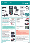
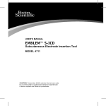
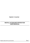
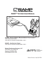
RAMP™ System User Manual
RAMP - Rapid Airway Management Positioner™
FOR SINGLE USE ONLY
FOR USE BY TRAINED PERSONNEL ONLY
RAMP - Air Supply Pump
FOR USE BY TRAINED PERSONNEL ONLY
Patient Positioning Systems, LLC
3003 West 11th, Suite 143
Eugene, OR 97402 USA
www.ppsproducts.com
www.patientpositioningsystems.com
Date of Issue: July 28, 2015
Table of Contents
1. symbols Reference................................................................................3
2. Intended Use...........................................................................................3
3. Contraindications...............................................................................4
4. Warnings, Cautions and Notes....................................................5
5. Parts List...................................................................................................8
6. Product Specifications.....................................................................9
6.1 Materials specifications............................................................9
6.2 Product dimensions......................................................................9
6.3 Patient weight limit.....................................................................9
6.4 Inflation/deflation valves.......................................................9
6.5 Storage............................................................................................... 10
7. Clinical Application......................................................................... 10
8. Use................................................................................................................11
8.1 Assembly..............................................................................................11
8.2 Joystick Operation...................................................................... 12
8.3 Foot Pedal Operation................................................................ 13
8.4 RAMP Positioning Device........................................................ 14
9. Inspection and maintenance....................................................... 15
9.1 Inspection.......................................................................................... 15
9.2 Maintenance................................................................................... 15
10. Appendix................................................................................................. 18
10.1 Electromagnetic Compatibility.......................................... 18
2
RAMP System User Manual - Table of Contents
1. Symbols Reference
The Rapid Airway Management Positioner (RAMP™)
positioning device manufactured by Patient Positioning
Systems, LLC is a single-use applied patient part (i.e., the
device comes in direct contact with the patient’s body). It
carries the following safety symbols:
The BF (body protected) symbol means that the
input connectors are suitable for connection to
humans provided there is no direct electrical
connection to the heart.
Please consult all accompanying instruction
before attempting to use the device.
This product is intended for single use
only.
Do not dispose of this product as unsorted
municipal waste. For more disposal information,
contact the manufacturer.
2. Intended Use
The intended use of the RAMP system is to pneumatically
position the head and torso of a patient lying in the supine
position without manual lifting.
RAMP System User Manual - 1. Symbols Reference
3
3. Contraindications
The RAMP system must not be used in cases of suspected
cervical spine injury or if a qualified healthcare provider
believes that such an application would endanger the
patient.
The inflatable RAMP positioning device should not be used
for patients weighing above 600 lbs (273 kg).
4
RAMP System User Manual - 3. Contraindications
4. Warnings, Cautions & Notes
Please read the instructions for use carefully.
4.1 Warnings
• Use the RAMP positioning device with a UL 60601
certified air supply only.
• During inflation of the RAMP positioning device,
air pressure must not exceed 4 PSI.
• To ensure a pressure no greater than 4 PSI, use
the RAMP positioning device with a wall-air setup
only if an approved in-line regulator is attached.
• Do not use the RAMP positioning device, air
supply or any of its components if they have been
damaged in any way.
• Perform a functional check before each use of the
RAMP positioning device.
• The inflatable positioning device is for single use
only. Do not attempt to clean and/or reuse this
portion of the device after the first use.
• The RAMP positioning device is only to be used by
trained personnel.
• The RAMP positioning device may be placed in a
suitable disposal container in accordance with
local guidelines for disposal of single-use medical
devices.
• To avoid risk of electric shock, this equipment
must only be connected to a supply mains with
protective earth.
• Do not modify this equipment
authorization of the manufacturer.
without
RAMP System User Manual - 4. Warnings, Cautions & Notes
5
4.2 Cautions
• Do not leave patients unattended when using the
RAMP system.
• Do not use the RAMP positioning device to transfer
or move the patient laterally or off the table as
injury may result.
• Have a second inflatable RAMP positioning device
or an alternative positioning method readily
available for use. The inflatable RAMP positioning
device is not sterile.
• Placing a sheet between the RAMP positioning
device and the patient does not prevent
contamination of the product.
• Ensure the device is positioned so that (emergency)
disconnect can be made of the RAMP positioning
device from the RAMP air supply pump and the air
supply pump can be unplugged from the electrical
wall outlet.
• The RAMP positioning device is for single use only.
• Incompatibility of technologies is always a
potential problem in the hospital environment.
Therefore, one should always be prepared for the
unexpected. The RAMP system air supply pump has
been designed and tested to be electromagnetically
compatibile with other medical equipment in its
electromagnetic environment. It does not emit
significant levels of electromagnetic energy that
can cause interference, and it conforms to the
following standards: CISPR-11:2010; IEC 610004-2:2010; IEC 61000-4-3:2010; IEC 61000 4-4:2010;
IEC 6100 5-5:2014; IEC 6100 5-6:2003; IEC 6100
4-8:2009 and IEC 61000 4-11:2004 (See certificate of
conformance in the Appendix).
6
RAMP System User Manual - 4. Warnings, Cautions & Notes
4.3 Notes
• The information given in this manual serves only
to instruct the user in the correct handling of the
RAMP system.
• The RAMP system is classified as a Class I device
by the FDA. The RAMP positioning device is
also classified as Class I Normal Flammability
as defined by the Consumer Products Safety
Commission’s Flammable Fabric Regulation, 16
CFR § 1610. However, users are advised to follow
standard safety protocols when using the product
near high-intensity heat sources.
• Patient Positioning Systems, LLC is not responsible
for any damage to the system or patient resulting
from incorrect use.
• The approved RAMP air supply unit meets medical
electronic interference requirements.
• Read these safety instructions carefully and keep
them for later reference.
• Service and maintain the RAMP system as specified
under Section 9, Inspection and Maintenance.
• The RAMP system is designed and tested to meet
the requirements of IEC 60601-1, Electrical Medical
Equipment - Part 1: General requirements for basic
safety and essential performance. Refer to this
standard regarding safety requirements for this
device.
RAMP System User Manual - 4. Warnings, Cautions & Notes
7
5. Parts List
The RAMP system consists of an applied patient positioning
device (pillow) (1), an air supply pump (2), a joystick (3),
two foot pedals (4), air tubings and fittings (5), and a cart
(6). Before installation and use of the system, ensure the
following items are available:
1
2
3
4
5
6
No.
Item
Part Number
1
RAMP single-use patient positioner
PPS-R1001
2
RAMP air supply pump
PPS-AP110-120V/
PPS-220-240VAC
3
RAMP joystick
PPS-AFP
4
RAMP foot pedals (2)
PPS-AJS
5
RAMP tubings/fittings
PPS-ATubing10
6
RAMP cart
PPS-Cart
Caution: The above parts are specified by the manufacturer as required for the safe
operation of the RAMP system. To maintain the warranty and ensure safety when
replacing parts, do not modify the specified parts or attempt to interchange the
specified parts with other parts. Should an attempt be made to use a non-manufacturer
interchangeable part, the device will not meet certified design or conformance standards.
The manufacturer provide information upon request to assist service personnel in
repairing those parts of the RAMP system that are designated by the manufacturer as
replaceable by service personnel.
8
RAMP System User Manual - 5. Parts List
6. Product Specifications
The RAMP positioning device inflates to lift and position
the head and torso of a supine patient for convenient and
effective positioning. The device has two chambers that
can be inflated separately, making it easier to achieve ear to
sternal notch positioning regardless of the patient’s body
habitus.
6.1 Material specifications
• Polyethylene, which has been tested to be
biocompatible in accordance with ISO 10993
standards
• DEHP free
• RF welding on all seams
• Latex free
6.2 Product dimensions
• Deflated: 43.75 in. L, 27 in. W
6.3 Patient weight limit
• Not to exceed 600 lbs (273 kg)
6.4 Inflation/deflation valves
• Inflation valves are located on the top portion of
the chambers
RAMP System User Manual - 6. Product Specifications
9
6.5Storage
Ambient
Temperature
Relative Humidity
28°C (82°F)
10°C (50°F)
75%
30%
Atmospheric
Pressure
1060 hPa
700 hPa
7. Clinical Application
The RAMP positioning device is a rapidly inflated,
customizable adjunct to facilitate proper positioning of
patients in need of airway management.
The RAMP system consists of a RAMP positioning device,
air tubing, a medically approved air supply, a single
axis proprietary joystick, and a hands-free foot pedal
configuration.
10
RAMP System User Manual - 7. Clinical Application
8. Use
The RAMP system ships with all fittings for assembly in
place.
8.1 Assembly
a. One end of the flexible air hose ships attached to the
air supply pump. The other end of the tubing connects
to the fitting located on the controller (i.e., foot pedals
or joystick).
2
TO INSERT: Push the
airline into the fitting.
The internal lock claws
grab and hold the airline.
1
TO REMOVE: Push the
airline and “release ring”
on the fitting down
firmly. Then, while still
holding “release ring”
down, pull the airline
out.
b. Take care to position the cart and other RAMP system
equipment to make it easy to connect/disconnect
the RAMP positioning device from the joystick or
foot pedals and to plug/unplug the air supply pump
electrical cord.
RAMP System User Manual - 8. Use
11
c.The RAMP positioning device (pillow) has two
independently controllable chambers that each has
a female fitting located along the seam. Connect
each chamber of the RAMP positioning device to the
air supply pump by utilizing the color-coded quick
connect/disconnect connectors.
8.2 Joystick Operation
a. The RAMP system may be controlled using a
proprietary single-axis joystick by joining each male
coupling with its corresponding female fitment—
simply insert and twist until the two pieces are snugly
attached. Should it become necessary to rapidly
deflate the RAMP device, the coupling may be easily
disengaged from the fitment by pushing forward
slightly and twisting.
Female fitment
Male coupling
b. The single-axis joystick
moves in each cardinal
direction to control
inflation/deflation of the
two chambers. Movement
upwards or “north” will
inflate the large chamber,
while deflecting the joystick
downwards or “south” will
deflate the large chamber.
Likewise, right/left or “east/west” movements will
control airflow into and out of the smaller chamber.
12
RAMP System User Manual - 8. Use
8.3 Foot Pedal Operation
a. The RAMP foot pedal assembly comes fully assembled.
Like the joystick controller, simply join each color
-coded male coupling with its corresponding female
fitment. Insert and twist until the two pieces are
snugly attached. Should it become necessary to rapidly
deflate the RAMP device, the coupling may be easily
disengaged from the fitment by pushing forward
slightly and twisting.
b. Depress the top of each foot pedal to commence
inflation. Each foot pedal will control the upper or
lower pillow chamber, respectively.
c. Depress the bottom of the foot pedal to allow air to
vent to the atmosphere and deflate the chamber.
Inflation
Deflation
d. When using the hands-free solution, toggle between
each foot pedal in a controlled fashion to slowly fill each
chamber. To deflate a chamber, depress the bottom of
the foot pedal to vent air to the atmosphere. When
using either controller, be mindful not to overinflate
either chamber.
e. To safety terminate the inflation operation, remove
feet from foot pedals and/or unplug the air pump
from the electrical wall outlet.
RAMP System User Manual - 8. Use
13
8.4 RAMP Positioning Device
a. After removing the product from its packaging,
begin set up by correctly situating the patient on
the deflated RAMP device. While locating the top of
the patient’s shoulder blades on the area that states
“NAPE OF NECK,” be sure to center the patient’s head
on the “T” mark printed on the smaller air chamber.
Correct positioning of the patient’s midline along the
“SPINAL ALIGNMENT” indicator will also help to
prevent rolling once the device is inflated.
b. If at any point the patient appears to be uncentered
or unstable, immediately deflate the RAMP device
and reposition the patient in accordance with the
instructions above. The large chamber accomplishes
most of the lifting, whereas the smaller chamber
located under the patient’s head is meant for finetuning the patient position and optimizing the
laryngeal view.
Fully Inflated Bag
c. Inflate the RAMP positioning device until the patient’s
ear canal is aligned with the sternal notch. Be mindful
of over-inflation.
d. For rapid deflation, disconnect the couplings from
the female fitments, and the air will immediately vent
from the chambers.
14
RAMP System User Manual - 8. Use
9. Inspection & Maintenance
9.1 Inspection
It is recommended that the RAMP positioning device,
joystick, foot pedal, air pump and air hoses be inspected
before each use to insure the system’s effective operation.
Items that should be inspected include the power cord
for damage, the positioning device and air hoses for cuts
and tears, and the foot pedal and joystick for any sticking.
Damaged parts on the positioning device should be replaced
immediately, and other components should be replaced as
soon as possible.
9.2 Maintenance
The RAMP positioning device is for single-use only and
should not be cleaned and reused. It should be disposed of
after each use according to hospital local procedures.
The RAMP air pump, foot pedal, joystick, and air hoses are
considered durable medical equipment. They are designed
to be used and then disinfected and put back into service.
Due to the environment that these components are
operated in, it is recommended that they be routinely
cleaned. In between patient use or whenever soiled, the air
pump and hose should be wiped down with a germicidal
solution (Phenolic is preferred), or as per hospital protocol
for a similar type of equipment. Use a clean sponge or paper
towels dampened with the germicidal solution to wipe down
all exterior surfaces. Wipe up any excess cleaning solution
with clean dry paper towels and dispose of or rinse out
cleaning tools properly. A diluted 1:10 solution of chlorine
RAMP System User Manual - 9. Inspection & Maintenance
15
bleach to water can be used, but note that stainless steel
surfaces must be immediately dried after application—
chlorine residues can be aggressive to stainless steel and
metals in general.
The RAMP air pump is expected to have a service life of
at least 10 years and should be disposed of according to
hospital procedures at the end of its service life.
Foot pedals have a service life of 5 years and should be
replaced at the end of their service life.
Tubing should be replaced annually (or sooner if there are
signs of excessive wear and tear). Replace the tubing by
firmly depressing the tubing and the plastic “release ring”
located on the fitting. The tubing should release. Then,
firmly insert the new tubing into the fitting.
Failure to replace any or all of these components could
result in air leaks or inflation difficulties.
The RAMP air pump utilizes a sock-type filter that filters
to two microns. This filter can be cleaned, sanitized and
placed back into service. To access the filter, remove the
screws that attach the stainless steel filter enclosure to the
main body of the motor housing. Release the ground strap
(green wire) and remove the stainless steel filter enclosure
off to the side. Remove the sock-type filter. The filter is held
in place by tension with elastic at the open end. Once the
filter is removed, clean under cold running water. Place
clean filter in a germicidal solution and let soak for five
minutes. A 1:10 solution of chlorine bleach to water can be
used. Remove from germicidal solution, and remove excess
solution. Ppaper towels can be used to accelerate drying—
place filter between towels and pat dry. Allow the filter to
thoroughly dry before reinstalling into the RAMP air pump.
16
RAMP System User Manual - 9. Inspection & Maintenance
The life of the filter is dependent upon environmental
conditions and the frequency of its cleaning. Patient
Positioning Systems, LLC recommends cleaning the filter
at least once a quarter. Filters should be replaced every two
to three years or as needed. Old filters should be disposed
of according to hospital procedures at the end of their
service life.
RAMP System User Manual - 9. Inspection & Maintenance
17
10. Appendix
10.1 Electromagenetic Compatibility
Recommended separation distances between portable and mobile
RF communications equipment and the RAMP System
The RAMP™ is intended for use in an electromagnetic environment
in which radiated RF disturbances are controlled. The customer
or the user of the RAMP can help prevent electromagnetic
interferences by maintaining a minimum distance between portable
and mobile RF communications equipment (transmitters) and the
RAMP system as recommended below, according to the maximum
output power of the communications equipment.
Rated
maximum
outputpower
of transmitter
Separation distance according to frequency of
transmitter
m
W
150 kHz to 80
MHz
80 MHz to 800
MHz
8000 MHz to 2,5
GHz
d=1,2
d=1,2
d=2,3
0,01
1,12
0,12
0,23
0,1
0,38
0,38
0,73
1
1,2
1,2
2,3
10
3,8
3,8
7,3
100
12
12
23
For transmitters rated at a maximum output power not listed
above, the recommended separation distance (D) in meters (m) can
be estimated using the equation applicable to the frequency of the
transmitter, where P is the maximum output power rating of the
transmitter in watts (W) according to the transmitter manufacturer.
NOTE 1
At 80 MHz and 800 MHz, the separation distance for the higher
frequency range applies.
18
RAMP System User Manual
NOTE 2
These guidelines may not apply in all situations. Electromagnetic
propagation is affected by absorption and reflection from structures,
objects and people.
Guidance and Manufacturer’s Declaration – Electromagnetic
Emissions
The RAMP is intended for use in an electromagnetic environment
as specified below. The customer or the user of the RAMP should
assure that it is used in such an environment.
Emissions Test
RF Emissions
Compliance
Group 1
The GLIDETM uses
RF energy only for
its internal function.
Therefore, its RF
emissions are very
low and are not
likely to cause any
interference in
nearby electronic
equipment.
Class A
The RAMP is
suitable for use in
all establishments
other than domestic
and those directly
connected to the
public low voltage
power supply
network that
supplies buildings
used for domestic
purposes.
CISPR 11
RF Emissions
CISPR 11
Harmonic Emissions
Electromagnetic
Environment
Class A
IEC 61000-3-2
Voltage Fluctuations
Flicker Emissions
IEC 6100-3-3
RAMP System User Manual
19