1
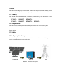
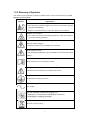
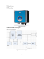
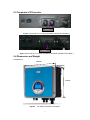
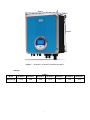
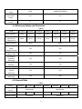
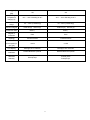
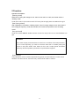
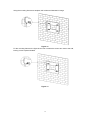
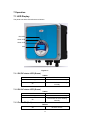
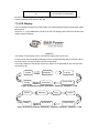
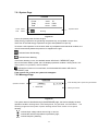
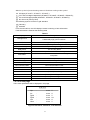
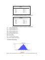
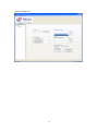
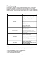
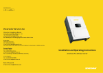
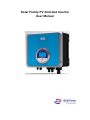
Solar Family PV Grid-tied Inverter
User Manual
Copyright Declaration
The copyright of this manual belongs to B&B Power Co., Ltd. (Here after to be referred as
B&B Power). Any corporation or individual should not plagiarize, partially copy or fully copy it
(including software, etc.), and no reproduction or distribution of it in any form or by any means.
All rights reserved. B&B Power reserves the rights of final interpretation. This information is
subject to modify without notice.
Table of Contents
1 Notes.............................................................................................................................................1
1.1 Validity ...............................................................................................................................1
1.2 Target Group .......................................................................................................................1
1.3 Safety ..................................................................................................................................1
2 Introduction ..................................................................................................................................5
2.1 Overview.............................................................................................................................5
2.2 Electrical Block Diagram....................................................................................................5
2.3 Terminals of PV Inverter.....................................................................................................6
2.4 Dimension and Weight ........................................................................................................6
3 Packaging List .............................................................................................................................8
4 Technical Data.............................................................................................................................9
4.1 Input(DC).......................................................................................................................9
4.2 Output(AC) ....................................................................................................................9
4.3 Efficiency Safety and Protection.......................................................................................10
4.4 General Data .....................................................................................................................10
5 Function......................................................................................................................................12
6 Installation ..................................................................................................................................13
6.1 Safety Instructions.............................................................................................................13
6.2 Selecting the Installation location .....................................................................................13
6.3 Preparation ........................................................................................................................14
6.4 Fixed the Mounting on the Wall........................................................................................14
6.5 Fixed the Inverter on the Wall...........................................................................................16
6.6 Check Inverter Installation Status .....................................................................................17
6.7 Connector Guide ...............................................................................................................17
7 Operation....................................................................................................................................20
7.1 LED Display .....................................................................................................................20
7.2 LCD Display .....................................................................................................................21
8 Setting up Communication ......................................................................................................27
8.1 Communication Interface Type.........................................................................................27
9 Troubleshooting.........................................................................................................................30
10 Decommissioning....................................................................................................................32
10.1 Dismantling.....................................................................................................................32
10.2 Packaging ........................................................................................................................32
10.3 Storage ............................................................................................................................32
10.4 Disposal...........................................................................................................................32
11 Warranty ...................................................................................................................................33
12 Contact B&B ............................................................................................................................34
1 Notes
This manual is an integral part of the inverter. Please read the product manual carefully before
installation, operation or maintenance. Keep this product manual for future reference.
1.1 Validity
This manual describes the assembly, installation, commissioning and maintenance of the
following inverters:
SF1600TL
SF3600TL
SF2200TL
SF4200TL
SF3000TL
SF4600TL
SF5000TL
1.2 Target Group
This manual is for qualified personnel. Qualified personnel have received training and
demonstrated skills and knowledge in the construction and operation of this device.
Qualified personnel are trained to deal with the dangers and hazards involved in installing
electric devices.
1.3 Safety
1.3.1 Appropriate Usage
The Solar Family Series are the PV inverters which convert the DC current of a PV generator
into AC current and feed it into the public grid.
PV Module
Grid-tied
Figure 1
PV Grid-tied System
1
Grid
1.3.2 Important Safety Instructions
Danger!
Danger to life due to high voltages in the inverter!
·All work on the inverter must be carried out by qualified personnel
only.
·The appliance is not to be used by children or persons with reduced
physical sensory or mental capabilities, or lack of experience and
knowledge, unless they have been given supervision or instruction.
·Children should be supervised to ensure that they do not play with
the appliance.
Caution!
Danger of burn injuries due to hot enclosure parts!
·During operation, the upper lid of the enclosure and the enclosure
body may become hot.
·Only touch on the lower enclosure lid is allowed during operation.
Caution!
Possible damage to health as a result of the effects of radiation!
·Do not stay closer to the inverter (beyond 20cm is available) for a
long time.
Note!
Grounding the PV generator.
·B&B Power recommends PV modules have an ICE 61730 Class A
rating. Please don’t connect the PV modules to GND.
2
1.3.3 Glossary of Symbols
This section gives a glossary of all the symbols shown on the inverter and the type label.
Symbols on the inverter
Symbol
Explanation
Danger to life due to high voltages in the inverter!
•There would be residual voltage in the inverter. The inverter requires
1 minute to discharging.
• Wait for 5 minutes before you open the upper lid or the DC lid.
Beware of hot surface.
·The inverter may become hot during operation. Avoid any contact to
the surface during operation.
Danger of high voltages
·Danger to life due to high voltages in the inverter!
Risk of electric shock!
·Only authorized personnel can be allowed to set the DIP switch
(SW1).
Requests the user to consult the manual
Indicates caution followed by important instructions
Equipment grounding conductor
AC voltage
You can operate the interface by tapping on it
·Tapping once: The background illumination switches on.
·Tapping again: Updating information.
Recovery and recycling.
3
● Symbols on the type label
Symbol
Explanation
CE mark.
·The inverter complies with the requirements of the applicable CE
guidelines.
TUV mark.
·The inverter complies with the requirements of the applicable TUV
guidelines.
SAA mark.
·The inverter complies with the requirements of the applicable SAA
guidelines.
、
● Important Safety Instructions
When using the product, please do remember the below information to avoid the fire, lightning
or other personal injury:
Warning!
Ensure that input DC voltage is less than Max. DC voltage.
·Over voltage may cause permanent damage to inverter or other
losses, which will not be included in warranty!
·This chapter contains important safety and operating instructions.
·Read and keep this operation Guide for future reference.
Warning!
· Authorized service personnel must disconnect both AC and DC
power from the B&B Power series inverter before attempting any
maintenance or cleaning or working on any circuits connected to
the B&B Power series inverter.
Warning!
· the photovoltaic array is exposed to light, it supplies a d.c. voltage to
the inverter.
4
2 Introduction
2.1 Overview
Figure 2 Stereogram
2.2 Electrical Block Diagram
● Electrical block diagram
Figure 3 Electrical block diagram
5
2.3 Terminals of PV Inverter
RS485
Figure 4 Terminals of PV Inverter (SF1600TL/SF2200TL/SF3000TL)
RS485
Figure 5 Terminals of PV Inverter (SF3600TL/SF4200TL/SF4600TL/SF5000TL)
2.4 Dimension and Weight
● Dimension
386mm
159mm
340mm
Figure6
SF1600TL/ SF2200TL/ SF3000TL
6
386mm
159mm
420mm
Figure7
SF3600TL/ SF4200TL/ SF4600TL/SF5000TL
●Weight
Table1
Model
SF1600TL
SF2200TL
SF3000TL
SF3600TL
SF4200TL
SF4600TL
SF5000TL
Weight [kg]
13.6
13.9
13.9
17.2
17.5
17.5
17.5
7
3 Packaging List
Table2
Item
Name
Quantity
A
Solar Inverter
1
B
Mounting Frame
1
C
Mounting Screws
4
D
Mounting Frame Screws Sleeve
4
E
Mounting Screws
2
F
Manual
1
The Solar Family is shipped with the following items:
F
Figure 8
8
4 Technical Data
4.1 Input(DC)
Table3
Model
Max. DC
Power[W]
SF1600TL
SF2200TL
SF3000TL
SF3600TL
SF4200TL
SF4600TL
SF5000TL
1700
2350
3150
3800
4400
4800
5200
1700
2350
3150
Max. DC power
each MPP tracker
3000
[W]
Max. DC
550
Voltage[V]
550
Max.Input
Current of MPP
8
10
15
15/15
Tracker[A]
Number of MPP
Trackers / Strings
1/1
2/1
250-500
250-500
370
370
120/150
120/150
Ⅱ
Ⅱ
per MPP Tracker
MPPT Voltage
Range (at full
power) [V]
Nominal PV
Voltage [V]
Shutdown Voltage
/
Start Voltage [V]
Overvoltage
category
4.2 Output(AC)
Table4
Model
Max. AC
Power[W]
Max. AC Current
[A]
SF1600TL
SF2200TL
SF3000TL
SF3600TL
SF4200TL
SF4600TL
SF5000TL
1600
2200
3000
3600
4200
4600
5000
7.8
11
14.5
18
21
22
24
Nominal AC
Voltage / Range
230/207-253
230/207-253
50/60
50/60
[V]
AC Grid
Frequency [Hz]
9
Power Factor
(cosφ)
>0.99
0.9lagging-0.9leading
<3%
<3%
Ⅲ
Ⅲ
THD
(at nominal
power)
Overvoltage
Category
4.3 Efficiency Safety and Protection
Table5
Model
SF1600TL
SF2200TL
SF3000TL
SF3600TL
SF4200TL
SF4600TL
SF5000TL
Max. Efficiency
97.5%
97.6%
97.6%
98.0%
98.0%
98.0%
98.0%
96.8%
96.9%
97.0%
97.3%
97.4%
97.4%
97.5%
Euro-Efficiency
(Nominal PV
Voltage 370V)
MPPT Efficiency
99.9%
99.9%
Yes
Yes
Yes
Yes
Yes
Yes
Yes
Yes
Yes
Yes
Yes
Yes
Yes
Yes
Overvoltage /
UnderVoltage Protection
Shutdown
Voltage / Start
DC Isolation
Impedance
Monitoring
Ground Fault
Protection
Grid Monitoring
Ground Fault
Current
Monitoring
DC Injection
Monitoring
4.4 General Data
Table6
Model
SF3600TL
Dimension(W/H/
Cooling Concept
SF4600TL
SF3600TL
386/340/155
D) [mm]
Weight [kg]
SF4200TL
13.6
13.9
SF4200TL
SF4600TL
SF5000TL
386/420/155
13.9
17.2
Convection
17.5
17.5
Convection
10
17.5
Noise (typical)
[dB]
<30
<30
-20℃~+60℃/derating at 45℃
-20℃~+60℃/derating at 45℃
4% ~ 100% (condensing)
4%~ 100% (condensing)
External (III)
External (III) Internal (II)
Operating
Temperature
Range [°C]
Relative humidity
range
Pollution Degree
Protective class
Degree of
Protection
Topology
Internal (II)
ClassⅠ
ClassⅠ
IP65
IP65
Transformerless
Transformerless
<0.5W
<0.5W
Backlight,16*4 character
Backlight,16*4 character
RS485/ Bluetooth optional
RS485/ Bluetooth optional
Internal
Consumption( ni
ght ) [W]
LCD display
Communication
Interfaces
Standard
Warranty
5/10/20 years
5/10/20 years
Free/opt./opt.
Free/opt./opt.
11
5 Function
Operation Condition
【Waiting Mode】
When the PV string DC voltage is over 120V but not reach to 150V, the inverter enters a
"Waiting mode".
Under this mode, it will continue check if PV array has enough power to feedback into grid.
【Self Testing Mode】
After initialization is finished in "Waiting mode", if the PV string voltage is over 150V and the
Grid voltage & frequency meets the standard, the inverter will operates in the "Checking
mode".
【On-grid Mode】
Under this mode, B&B SF series inverters convert PV array’s DC into AC and feedback into
grid.
CAUTION!
The inverter output power decrease is usual in the condition of thermal protection,
but if it occurs frequently, you need to check the heat sink or consider putting the
inverter in the place where have better air flow, and if output power decreases
caused by electrical problem, please ask for professional supports.
【Fault Mode】
If any fault/error occurs, inverter stops delivering power until the fault/error is clear. Some
fault/error will auto recover, and some may need manual restart to resolve.
12
6 Installation
6.1 Safety Instructions
Do not remove the enclosure upper lid. Inverter contains no user practical parts. All wiring and
electrical installation should be conducted by a qualified service personnel and must meet
national requirements.
Both AC and DC voltage sources are terminated inside the PV Inverter. Please disconnect
these circuits before servicing.
When a photovoltaic panel is exposed to light, it generates a DC voltage. When connected to
this equipment, a photovoltaic panel will charge the DC link capacitors.
Energy stored in this equipment’s DC link capacitors presents a risk of electric shock. Even
after the unit is disconnected from the grid and photovoltaic panels, high voltages may still
exist inside the PV-Inverter. Do not remove the upper lid until at least 5 minutes after
disconnecting all power sources.
This unit is designed to feed power to the public power grid only. Do not connect this unit to an
AC source or generator. Connecting inverter to external devices could result in serious
damage to your equipment.
Carefully remove the unit from its packaging and inspect for external damage. If you find any
imperfection, please contact with your local distributor or service center.
Although designed to meet all safety requirements, some parts and surfaces of Inverter are
still hot during operation. To reduce the risk of injury, DO NOT touch the heat sink at the back
of the PV-Inverter or nearby surfaces while Inverter is operating.
Check environment where system is installed.
Check whether the installation site fall into any of the following conditions:
● The ambient temperature is beyond the range of the optional temperature limitation. ( -20°C
to +60°C, -4°F to +140°F),(Power derating begins at 45°C).
● Installation altitude is higher than 2000m.
● Prone to be damaged by sea water
● Close to corrosive gas or liquid (for example, locations where chemicals are processed or
the location where feed lots of poultry).
● Exposed to direct sunlight.
● Prone to be damaged in flooding or icing time
● Little air flow or high humidity.
● Exposed to steam, vapor, or water.
● Exposed to direct cool air.
● Close to the television antenna or antenna cable.
6.2 Selecting the Installation location
The installation method and mounting location must be suitable for the
weight and dimensions of the inverter. Select a wall or solid vertical surface which is able to
support the PV Inverter.
Mount on a solid surface, the mounting location must be accessible at all times.
Vertical installation or tilted backwards by max. 15°.
13
The connection area must point downwards.
Do not install horizontally
Figure 9
6.3 Preparation
Below tools are needed before installation.
Figure 10 installation Tools
6.4 Fixed the Mounting on the Wall
Inverter requires adequate cooling space. Allow at least 20cm space above and below the
inverter.
Figure 11
14
Using the mounting frame as a template, drill 3 holes as illustrated in image
Figure 12
Fix the mounting frame as the figure shows. Do not make the screws too close to the wall,
leaving 2-4mm exposed instead.
Figure 13
15
6.5 Fixed the Inverter on the Wall
Hang the inverter onto the mounting frame.
Figure 14
Insert safety- lock screws into the bottom leg to fasten the inverter.
Figure 15
16
6.6 Check Inverter Installation Status
Check the upper straps of Inverter to ensure it fixed on to the bracket
Check the secure mounting of the PV-Inverter by trying to raise it from the bottom.
The PV-Inverter should remain firmly attached.
Select the installation location so that the status of display can be easily viewed.
Choose a strong mounting wall to prevent vibrations while inverter is operating.
6.7 Connector Guide
This product has a professional IP68 DC waterproof connector. You have to wire DC by
yourself. Please see figure 14 and 15 for DC connector disassembling guide.
Connectors must only be connected by qualified personnel
Only PV1-F cables can be used. The TÜV approval only allows the use of PV1-F cables. Do
not use type H07RN-F cables.
The connectors must be not disconnected while under load. For protection against electric
shock, connectors must always be disconnected from the power supply during assembly.
Connectors that are not plugged must be protected against humidity and contamination by a
protective cap. Any kind of contamination may have adverse effect on the system and great
care must be taken during assembly to ensure that everything is clean.
Connectors provide IP68 protection but should not be continually exposed to water (e.g.
immersed under water) and not placed directly on the top side.
Connecting to PV panel (DC input):
Figure 16
1. Insert the stripped conductor.
Cross-sections: 2.5 to 6 mm2
Outside diameter: 5.0 to 8 mm
Stripping length: 15 mm
2. Close spring with the thumb or using combination pliers.
17
Please ensure that the spring is closed. (see fig14.)
3. Push connectors together. (see fig15.)
Screw cable gland tight. Screw in the nut until it reaches the O-ring and then tighten it with at
least 2 Nm using a suitable tool. Finished!
Connector/socket unlocking process:
Figure 17
1. Insert screwdriver SZF 1 or phase tester in one of the illustrated positions.
2. Leave screwdriver inserted and remove connector from socket.
Conductor reconnection to the:
Figure 18
1. Screw on the cable gland.
2. Never open the interlock as shown in the figure by using the screwdriver.
3. Pull plug connectors apart.
4. Open spring with screwdriver and remove conductor.
18
Figure 19
Connecting to the grid:
1.Measure grid voltage and frequency. It should be 230VAC, 50HZ and single phase.
2.Open the breaker or fuse between inverter and utility.
3.For inverter, connect AC wires as follows:
Figure 20
Below is the AC cable specification table when select the cable for installation.
Table 7 Cable and Micro-breaker Requirement
Model
SF1600TL
SF2200TL
SF3000TL
SF3600TL
SF4200TL
SF4600TL
SF5000TL
Cable (Cu)
2.5mm2
2.5mm2
2.5mm2
4mm2
4mm2
4mm2
4mm2
Micro-Breaker
16A
20A
20A
25A
25A
25A
32A
19
7 Operation
7.1 LED Display
The panel has three LED indicators as follows:
Red LED
Green LED
Green LED
LCD
Figure 21
7.1.1 DC/DC status LED (Green)
Table8
Off
The DC/DC Circuit is off.
Blinking
The DC/DC Circuit is starting.
The DC/DC Circuit is working
On
normally
7.1.2 DC/AC status LED (Green)
Table9
Off
The DC/AC Circuit is off.
Blinking
The DC/AC Circuit is starting.
The DC/AC Circuit is working
On
normally.
7.1.3 Fault LED (Red)
Table10
Off
No Error occurs
20
On
The inverter is in fault status
Normally, after starting up, DC/DC LED and DC/AC LED will be lighted indicating that the
Inverter's feeding power status to the grid.
7.2 LCD Display
The LCD display monitors the inverter status and collects statistical data for assessing system
performance.
Once turn on , Logo “B&B Power” will show on the LCD display, after a few seconds the index
display image will appear:
Figure 22
The display on the inverter can be controlled by tapping the front of LCD.
To save power, the LCD display’s backlight will turn off automatically after 30 seconds. When
the LCD is dark, one tap will make it become bright again.
A summary diagram of the display functions is shown as the figure below, the LCD will show
next page by tap.
System
Setting
In & Out
Message
Power Chart
Information
Figure 23 Summary diagram of SF1600TL, SF2200TL, SF3000TL’s LCD
System
Setting
Message
Input
Information
Output
Power Chart
Figure 24 Summary diagram of SF3600TL, SF4200TL, SF4600TL, SF5000TL’s LCD
21
7.2.1 System Page
SYSTEM
Power
Fault
Power
:
xxxxx
W
Today
:
xxxxx
KWH
Total
:
xxxxx
KWH
Status
Operation Mode
Waiting
Status
Figure 25
Power: the present power fed into the grid;
Today: Energy exported to the grid during the present day, and updated once per hour;
Total: Sum of the total energy exported to the grid, and updated once per day.
To ensure a safe operation of the inverter under any temperature and electrical condition, the
unit will automatically derate the power to be supplied to the grid.
: Indicate Power No Derating;
: Indicate Power Derating.
If the Power derating occurs, the detailed reason will show in “MESSAGE” page.
Next to the Power status symbol, the LCD displays operation condition: Waiting Mode, Self
Testing Mode, On-grid Mode, and Fault Mode.
: Indicate the inverter occur some faults, and the detailed information will show in
“MESSAGE” page
If the inverter has no fault, the symbol will disappear.
7.2.2 Message Page
MESSAGE
Operation Condition
Waiting
I G
1. Grid Fault
Power Derating reason symbol and grid standard
Warning or fault info.
Figure 26
The system status is identified through the MESSAGE page; the first line displays inverter
operation condition: Waiting Mode, Self Testing Mode, On-grid Mode, and Fault Mode.
following images are the symbol of power derating reason when inverter occurs power
derating.
: Indicate input voltage values are too high or too low;
: Indicate the ambient temperature is particularly high;
: Indicate frequency derating.
22
The
After the symbol of power derating reason is Real-time working mode symbol.
N PV Mppt (SF1600TL, SF2200TL, SF3000TL);
I
PV1 and PV2 Mppt independent (SF3600TL, SF4200TL, SF4600TL, SF5000TL);
P PV1 and PV2 Mppt parallel (SF3600TL, SF4200TL, SF4600TL, SF5000TL);
D DC Source In (Factory Test).
The following symbol is Real-time grid standard.
G Germany
A Australia
From the second line, the LCD displays inverter’s warning or fault information:
Fault Information is listed as the following table
Table11
Display
Description
The internal hardware that measures ground fault has measured
Leakage Fault
substantially high ground currents.
Grid Fault
Grid Voltage or Frequency out of range
Boost Fault
Boost(DC/DC) Power Stage fault
PV Over Voltage
PV panel Voltage too high
Relay Fault
The AC relay failed
DCINJ High
Output Current DC Offset too high
The RCD measurement mechanism has failed during the wake-up
RCD Fault
test phase.
Ov Temp
Over temperature
DC Bus High
DC Bus Voltage Fault
Grid Lock Failed
Grid Phase Lock failed
CPU Commu Failed
CPU Communication Fault
Aux Power Fault
+12V Power fault
ISO Fault
Isolation Fault
Inv Fault
Inverter(DC/AC) Power Stage fault
Boost Ov Curr
Boost (DC/DC) Power Stage over current
INVOvCurr
Inverter(DC/AC) Power Stage over current
PVPowerLow
PV Power too low
7.2.3 In & Out page
The inverter parameters will be displayed in this page.
IN & OUT
Vpv
Ipv
Vgrid
Fgrid
Iout
Vbus
:
:
:
:
:
:
xxxxx V
xxxxx A
xxxxx V
xxxxx Hz
xxxxx A
xxxxx V
Figure 27 SF1600TL, SF2200TL, and SF3000TL
23
INPUT
Vpv1
Ipv1
Vpv2
Ipv2
xxxxx
xxxxx
xxxxx
xxxxx
:
:
:
:
V
A
V
A
Figure 28 SF3600TL, SF4200TL, SF4600TL, and SF5000TL
OUTPUT
Vgrid
Fgrid
Iout
Vbus
:
:
:
:
xxxxx V
xxxxx Hz
xxxxx A
xxxxx V
Figure 29 SF3600TL, SF4200TL, SF4600TL, and SF5000TL
Vpv : Voltage for battery array;
Ipv : Current from battery array;
Vpv1 : Voltage for battery array 1;
Ipv1 : Current from battery array 1;
Vpv2 : Voltage for battery array 2;
Ipv2 : Current from battery array 2;
Vgrid : Grid Voltage;
Fgrid : Grid frequency;
Iout : Current exported to the grid;
Vbus : DC bus voltage of the inverter;
7.2.4 Power Chart Page
Figure 30
Graph of the power produced in the present day from 4 to 22 hours will be displayed in this
24
page.
7.2.5 Information Page
INFORMATION
SN
:
SwVer :
SFXXXXXXXXXXX
V100V100
B&B Power Co., Ltd.
www.bbpower.cn
Figure 31
SN : provides the production No. of the inverter.
SwVer : provides the production Firmware version of the inverter;
7.2.6 Setting Page
SETTING
Country
Lang
Addr
Mode
Date
Time
:
:
:
:
:
:
XXX
English
1
PV Mppt
yy-MM-dd
hh:mm:ss
Figure 32
Country: The country of the Inverter can work.
Mode: Work mode of the Inverter. It includes: PV Mppt, Dc In (Factory Test), IN1 & IN2 I (PV1
and PV2 Independent), IN1 & IN2 P (PV1 and PV2 Parallel);
Date: the present date of the inverter;
Time: the present time of the inverter.
Setting language
In the “SETTING” page, double tap to activate the Setting function, Language item become
bright: Lang, then double tap again, enter to change the language option, tap to select the
language and wait until the display become dark. But only English is available at now.
Setting communication address
When several inverters are connected to the same communication channel, each unit must
have a different address.
In the “SETTING” page, double tap to activate the Setting function, Language item become
bright: Lang, then tap again, Com Address item become bright: Addr, then double tap, enter to
change the Com Address option, tap to select the Com Address and wait until the display
become dark.
Setting working mode
If B&B Solar Inverter need change working mode when it is first installed, it can be set by BB
25
SolarInv Setting Tool.
26
8 Setting up Communication
8.1 Communication Interface Type
This product has a communication interface RS232, RS485 and Bluetooth (optional).
Operating information such as output voltage, current, frequency, fault information, etc., can be
delivered to PC or other monitoring equipment via RS485.
8.2 Communication
When user want to know the information of the power station and manage the entire power
system. We offer below three types of communications.
RS232 Communication (One inverter)
RS232 is one standard communication interface. For communication cable, one end is male
connector, the other end is female connector.
Grid-tied
Inverter
PC
RS232
Max 12m
Figure 33 RS232 Communication Diagram
RS232
RS485
Figure 34 Communication Interface of B&B Series Inverter
RS232 Pin Definition
Table12
Pin
1
2
3
4
Function
RXD
TXD
SGND
VCC
RS485 Communication (One inverter or several inverters)
RS485 is generally for multi inverters’ communication. Up to 32 inverters could communicate
at the same time, but wire length should be ≤1200m.
Select high-quality network cable; peel the isolation surface, Select 8-wires (orange white,
orange, green white, blue, blue white, green, brown white, brown), then follow the same order
with the press pliers push into the 8-wire RJ45 crystal head.
27
Figure 35 8-line RJ45
Table13 8-line RJ45
8-line RJ45 Wire No.
Function
Wire Color
1
NC
Orange white
2
NC
Orange
3
NC
Green white
4
GND
Blue
5
GND
Blue white
6
NC
Green
7
A
Brown white
8
B
Brown
■RS485 bus connection method
The connection between B&B Inverters uses a straight through cable. But the connection
between B&B Inverter and Webbox uses a crossover cable. As shown in the following figure.
Figure 36 B&B Web Box Monitoring Diagram
28
■ Connect the system by RS485 /RS232 Adapter
Grid-tied Inverter
Grid-tied Inverter
RS485
RS485
RS485
adapter
RS232
PC
Figure 37
Bluetooth Communication (optional)
Bluetooth module is a hardware device can be inserted to inverter’s RS232 port. Please refer
to B&B Bluetooth module Manual for more information.
29
9 Troubleshooting
In most situations, the inverter requires very little maintenance. However, if Inverter fails to
work perfectly, please refer to the following instructions before calling your local dealer.
Should any problem arises, the LED on the front panel will be red and the LCD will display the
relevant information. Please refer to the following table for a list of potential problems and
solutions.
Table 14 Troubleshooting list
Faults
Diagnosis and Solutions
-Waiting for one minute, grid will go back
to normal working state.
-Making sure that grid voltage and
frequency complies with standards.
-Or, please seek for help from us
Grid Fault
-Off to grid.
-Please check grid-connection, like wire,
interface, etc.
-Checking grid usability.
-Or seek for help from us.
-Checking the panel’s open-circuit voltage
whether the value is
PV Over Voltage
similar or already >Max.DC voltage.
-Please seek help from us when voltage ≤
Max.DC voltage.
-Disconnect the PV (+), PV (-) with DC
input, then reconnect them.
-Check L line and N line to see whether it
DCINJ High
has connection faults.
-Please seek for help from us when this
fault happens.
-Disconnect the PV (+), PV (-) with DC
input, then reconnect them.
Relay Fault
-Please seek for help from us if it can not
go back to normal state.
● Check the warning or fault messages on the information panel. Record the message if
displayed for further action.
● Try the solution indicated in Table 14.
● If your inverter information panel didn’t have a Fault light, check the following list to make
sure that the present state of the installation allows proper operation of the unit.
— Is the inverter located in a clean, dry, ventilated place?
— Have the DC input breakers been opened?
— Is the size & length of cables suitable?
30
— Are the input and output connections and wiring in good condition?
— Are the configurations settings correct for your particular installation?
—Are the display panel and the communications cable properly connected without damage?
Contact B&B Power Customer Service for further assistance. Please provide your details of
installation, model & serial number of the unit to us when inquiry.
31
10 Decommissioning
10.1 Dismantling
● Disconnect the inverter from DC input and AC output.
● Remove all connection cables from the inverter.
● Remove the inverter from the bracket.
10.2 Packaging
If possible, it’s better to pack the inverter with the original packing.
If original packing is not available, please use similar packing which meets below requirements
● Load ability should be over 20kg.
● With handle.
● Able to fully closed.
10.3 Storage
Store the inverter in a dry place where ambient temperature is always between -20 ℃ and
+60 ℃. -4°F to +140°F.
10.4 Disposal
Please put the wasted inverters & packing materials to a place which is convenient for relevant
department to dispose and recycle.
32
11 Warranty
Warranty certificate represents a five year warranty service for mentioned products since the
date of purchase.
Warranted Products
This warranty is applicable solely to the following products:
SF1600TL SF2200TL SF3000TL
SF3600TL SF4200TL SF4600TL SF5000TL
Limited Product Warranty
(Applicable under normal application, installation, use and service conditions.)
B&B warrants the above listed products to be free from defects and/or failure specified for a
period not exceeding five years from the date of sale as shown in the roof of Purchase to the
original purchaser.
33
12 Contact B&B
If you have any questions about B&B series inverter, please call service support hotline:
+86 755 8656 7100. Please keep following information to better our service for you. (Please note
and advise below information to us before inquiry for better service).
a. Inverter’s Model.
b. Inverter’s Serial No..
c. Communication Method.
d. PV Modules’ Model.
B&B Power Co., Ltd.
Marketing & Sales Office (Sales & Marketing Department)
Add: B Block, Junxiangda Building, No.9 Zhongshan Park Rd, Nanshan District, Shenzhen, China
Tel: +86 755 8656 7096
Fax: +86 755 8656 7102
Web: www.bbpower.cn
E-mail: [email protected]
Info & Service Office
Tel:+86 755 8656 7096
Fax: +86 755 8656 7102
E-mail: [email protected]
34