1
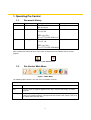
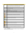
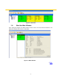
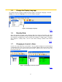
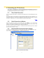
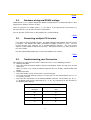
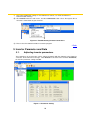
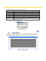
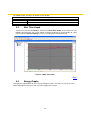
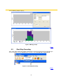
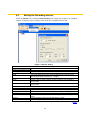
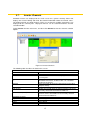
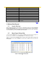
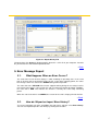
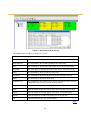
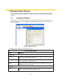
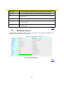
Pro Control User Manual
Version 1.2 2010.08
Contents
1.
2.
3.
4.
5.
6.
Operating Pro Control
1.1.
Document History
1.2.
Pro Control Main Menu
1.3.
Root List
1.4.
Start the Main Window
1.5.
Change the Display Language
1.6.
Standby Mode
1.7.
Changing an Inverter’s Name
Connecting your PV Inverter(s)
2.1.
Direct Serial Connection
2.2.
Serial Connection via Modem
2.3.
Serial and Ethernet Communication Settings
2.4.
Hardware wiring and RS485 settings
2.5.
Connecting multiple PV Inverters
2.6.
Troubleshooting your Connection
Inverter Parameter and Data
3.1.
Adjusting inverter parameters
3.2.
History Graphs
3.3.
Real Time Graph
3.4
Energy Graph
3.5.
Start/Stop Recording
3.6.
Setting the Recording Interval
3.7.
Inverter Channels
History Data Record
4.1.
Inverter Data Log
4.2.
Export/Import History Data
Error Message Report
5.1.
What Happens When an Error Occurs?
5.2.
How do I Export or Import Error History?
Message Report Settings
6.1.
Configuring Reports
6.2.
Mail Report Format
2
1. Operating Pro Control
1.1.
Document History
Version
1.0
Date
16-Dec-2009
1.1
26-Jan-2010
1.2
26-Aug-2010
Description
The First official release of
this document.
Pro Control :
Ver.2.5.0.6
Author
Scott Lin
Scott Lin
EZ Logger Lite:
Ver.3.1.CV93.EZ.NOB.9917
Pro Control :
Scott Lin
Ver.2.5.1.0
EZ Logger Lite:
Ver.3.1.CV93.EZ.NOB.0305
After installing Pro Control, locate its icon or the desktop shortcut and double-click to start the
program.
Figure 1-1 Pro Control Icons
1.2.
Pro Control Main Menu
Figure 1-2 Main Menu
The following table introduces the main menu and toolbar shortcuts.
Table 1-1 Pro Control Main Menu and Toolbar
Field
Definition
File
Use this menu to export or import inverter data, view the error history, or exit this
program.
Setting
Use this menu to configure the communication methods, change the language,
choose a background images, configure how Pro Control sends reports, and send
test Mail, SMS, and FAX alerts.
3
Inverter
Use this menu to remove or reconnect networked inverters, change the monitored
channels, define group settings and view group graphs, directly edit parameter
settings on the inverter itself, generate real-time and history graphs, assign an
alias for the current inverter, or reset the total converted energy and the hours of
operation of operation counter for the currently selected inverter.
Record
Use this menu to set the sampling rate and schedule for recording inverter data,
and start and stop recording.
EZ Logger
Use this menu for the currently selected EZ Logger, to connect, backup or restore
recorded data, clear recorded data, display the available memory, or assign an
alias description.
View
Use this menu to customize the displayed toolbars.
Help
Use this menu to open this help file or view software version information.
Click this button to export/import the selected inverter’s data
Click this button displays the error history for the current inverter
Click this button change report settings
Click this button change inverter parameters
Click this button generate a graph of the current inverter data
Click this button change the record settings
Click this button backup/restore EZ Logger data
Click this button view EZ Logger memory status
Click this button generate an energy graph of the current inverter data
1.3.
Root List
Currently connected inverters are displayed in the Root-List on startup. The following figure
displays the root list populated with inverters.
4
Figure 1-3 Overview
1.4.
Start the Main Window
After starting the program, the Main window is blank. Select an inverter from the Root-List. The
right panel displays that inverter’s information.
Figure 1-4 Main Window
→Back
5
1.5.
Change the Display Language
The software interface supports multiple languages option. To change the language, select the
Setting menu and then Language to see a list of available languages.
Figure 1-5 Changing Language
→Back
1.6.
Standby Mode
After a long period of inactivity, most computers will enter a power saving mode, and switch
off the hard disk. This program will stop recording when your computer enters standby mode.
For continuous monitoring you need to disable your computer’s standby mode. To disable
your computers standby mode, click the Start Menu->Settings->Control Panel->Power
Options.
→Back
1.7.
Changing an Inverter’s Name
Inverters are listed under their serial number. You may want to change the serial number to
a meaningful name such as the inverter type or location. Double click the left mouse button
over the desired inverter, and then type in the new alias. Now press the ‘enter’ or ‘return’ key
to keep the new name.
Figure 1-6 Changing an Inverter’s Name
→Back
6
2. Connecting your PV Inverter(s)
Every inverter is equipped with a serial port. Directly connect your inverter to your PC via a
serial cable and the RS232 ports on the corresponding devices. Alternatively, you can use
the RS232 port to connect the inverter to a modem.
2.1.
Direct Serial Connection
Connect an RS232 cable from the serial port on your computer to the corresponding port on your
inverter.
The default settings of Pro Control are already optimally configured for most equipment. It is
recommended that these settings with exception to the Com Port remain unchanged. To display
or edit these settings please see Serial and Ethernet Communication Settings.
→Back
2.2.
Serial Connection via Modem
Connect the modem to your PC via the RS232 port. Select Modem, in the communication
settings. Now enter the dial number of the receiving modem connected to the inverter. After
connection is established, available inverters display in the Root List.
The cable to connect inverter to modem is a dedicated female-to-female type. Please contact
your local dealer to obtain this cable.
2.3.
Serial and Ethernet Communication Settings
To configure Pro Control for Ethernet or serial (RS232) connection, click Setting from the main
menu, and then select Communication. The following window displays.
Figure 2-1 Communication Setting
7
The following table describes the fields in this screen.
Table 2-1 Communication Settings
Field
Definition
RS232
Com Port
Select Com Port connected from your PC to the modem.
Enable
Click to enable serial communication
Baud Rate
This field specifies the maximum number of bits transmitted per
second. The default Baud Rate setting is set to AUTO. However, if the
Pro Control cannot find your inverter, select the lowest Baud Rate.
Once connection is established, you can try faster rates to obtain the
best connection.
Parity
Setting the parity is optional and used for error checking. Select from odd,
even, or None (default).
Data Bits
This field specifies how many bits are sent with each packet of data. The
default value is 8 and corresponds to the same settings on the remote
inverter.
Stop Bits
The stop bit duration indicates the end of data transmission (default setting
is 1).
Media
Modem
Select the method of connection to your inverter. Use Direct if the inverter
is connected to your PC with a serial cable. Select Modem if your inverter
is remotely connected via a network.
Dial No.
Enter the number of the receiving modem.
Status
This field displays the inverter connection status.
Direct
Ethernet
Multiple inverters can be monitored remotely over an Ethernet network. You need to know the IP
address of each inverter you wish to connect.
< Add / > Remove
To add a remote inverter to the list of remote inverters, type its IP Address
and then click < Add.
To remove an entry from the list of remote inverters, select the inverters IP
address and then click > Remove.
IP Address
Enter the IP address of the remote inverter and click < Add to append that
inverter to the list of remote inverters.
Port No
The default port settings for all inverters is 5050
Cancel
Click this button to exit the current window without saving.
Ok
Click this button to save your settings and exit the current window.
8
→Back
2.4.
Hardware wiring and RS485 settings
RS485 interface uses a higher voltage than RS232, and therefore it is recommended for use over
long distances between inverters and PC.
There are four pins in a RS485 card, T+, T-, R+, and R-. If you want to link each inverter by a
four-wire cable, be sure to make the correct connections.
You can also link each inverter via the telephone line (recommended).
→Back
2.5.
Connecting multiple PV Inverters
If you want to connect multiple inverters, the optional RS485 card (optional) for each inverter
is required. The RS485 card allows connection of multiple inverters in series. The first
inverter connects your computer via an RS485-to-RS232 converter. The next inverter
connects to the RS485 card of the first inverter. Subsequent inverters are daisy chained in
the same fashion.
For more detailed information please refer to the RS485 card’s manual.
→Back
2.6.
Troubleshooting your Connection
If the Root-List is empty then no inverter is detected. Please see the following procedure:
a) RS232 Connection
• Check the cable connections between inverter and computer. Make sure both ends are well
connected.
• Make sure there is no card in the RS485 expansion slot as it disables communication with
RS232.
b) RS485 Connection
• Check the RS485 card on each inverter is inserted correctly.
• Check the connection between inverters. The four wires on each terminal blocks (R+, R-, T+,
T-) are fully secured.
• Check the wire connections on the RS485-to-RS232 converter. The terminals (R+, R-, T+,
T-) on RS485 card must be connected to (T+, T-, R+, R-) respectively on the converter as
the following table displays.
Table 2-2 Wire Communication Exchange
RS485-to-RS232
converter
The inverters communication
card
R+
T+
R-
T-
T+
R+
T-
R-
9
c) Check the COM PORT settings in Pro Control are correct; see Serial and Ethernet
Communication Settings
d) Click Inverter from the main menu, and then Connection. Now select “Re-register All” to
refresh the connections to your inverters.
Figure 2-2 Troubleshooting Inverter Connections
e) Please close Pro Control and then restart the program.
→Back
3. Inverter Parameter and Data
3.1.
Adjusting inverter parameters
The parameters of each inverter can be adjusted remotely with Pro Control. In the Root-List
select the desired inverter to change. Click Inverter in the main menu and then Parameter,
to enter the parameter settings window.
Figure 3-1 Parameter Setting
10
The following table describes the parameters in this screen.
Parameter
Vpv-Start(V)
T-Start(Sec)
Vac-Min(V)
Vac-Max(V)
Fac-Min(V)
Fac-Max(V)
Zac-Max(mOhm)
Dzac(mOhm)
Table 3-1 Parameter Setting
Definition
This is the voltage required to start the inverter.
This is the time delay between reconnecting to the grid (i.e. after a fault)
This is the minimum voltage that the inverter maintains grid connection.
This is the maximum voltage that the inverter maintains grid connection.
This is the maximum frequency that the inverter maintains grid connection.
This is the maximum frequency that the inverter maintains grid connection.
This is the maximum impedance that the inverter maintains grid connection
This is the maximum rate of change of impedance allowed by the inverter
to maintain grid connection.
To avoid accidental alteration of parameter settings, a password is required. To obtain this
password please contact your local dealer.
Figure 3-2 Password
→Back
3.2.
History Graphs
To display the data history graph for an inverter, first select the inverter’s name in the Root List.
Now go to the main menu and select Inverter and then Graph. Choose History Graph to plot
inverter data over a specified period.
Figure 3-3 History Graph
11
The following table describes the buttons in this window.
Table 3-2 History Graph
Button
Definition
Print
Click this button to print the current graph
Prev
Click this button to scroll the timeline backwards to an earlier record.
Next
Click this button to scroll the timeline forwards to a later record.
3.3.
Real Time Graph
Select an inverter from the Root list, and then click Real Time Graph on the main panel. The
following graph displays the current voltage and power output to the grid according to a time
interval set in the Record Settings screen (see Setting the Recording Interval)
Figure 3-4 Real Time Graph
→Back
3.4.
Energy Graphs
To display the output power for an inverter or multiple inverters, first move the cursor to screen,
double click right key of mouse and select EZ -Logger then inverter.
12
As the following windows display.
Figure 3-5 Energy Graph
→Back
3.5.
Start/Stop Recording
After starting Pro Control, the program automatically records the inverter data. To manually begin
or end a recording select the Record menu and then select Start Record or Stop Record.
Figure 3-6 Start/Stop Recording
→Back
13
3.6.
Setting the Recording Interval
Select the Record menu and then Record Setting. To change the frequency of recording
samples, change the value (seconds) in the “Real Time Sampling Interval” field.
Figure 3-7 Record Setting
Table 3-3 Record Setting
Field
Definition
Real Time Sampling Interval
(1~1000) Seconds
Enter the delay in seconds between data record entries.
Data Recording Interval
Auto
Select this option to have Pro Control automatically record inverter
data during periods of activity (i.e. sunlight).
Manual
Select this option to set a fixed time period to record inverter data.
From
Enter the time in 24-hour format for Pro Control to start monitoring
inverter data.
To
Enter the time in 24-hour format for Pro Control to stop monitoring
inverter data.
History Data Sampling Interval
Select the period in seconds to display the Daily history graph.
Daily
Select the period in hours to display the Monthly history graph.
Monthly
Select the period in minutes to display the Weekly history graph.
Weekly
Select the period in hours to display the Yearly history graph.
Yearly
Default
Click this button to return the Record Settings back to their original
values.
Cancel
Click this button to close this window without saving.
OK
Click this button to save the current settings and close this window.
→Back
14
3.7.
Inverter Channels
Available inverters are displayed on the main screen on a grid of summary boxes that
displays the inverter identity and fields that contain information about the internal status.
The displayed fields are called channels. There are 18 channels available, from which 5 are
displayed on the summary box. Displayed channels can be customized with the channel
selection window.
Select Inverter from the main menu, and then click Channel to view the channel selection
options.
Figure 3-8 Inverter Channels
The following table describes the fields in this screen.
Field
Overview
Selected Channels
>
<
Default
Channel Selection For
This device
All devices of (model)
Available Channels
Vpv1
Vpv2
Vpv3
Ipv1
Table 3-4 Inverter Channels
Definition
This field lists the channels that display on the inverter
summary box.
Select a channel in the Selected Channel list or the
Available Channel list, and then click < or > to add or
remove that channel.
Click this button to return the channel lists back to their
original settings.
Enable this field to apply the Selected Channel list to the
currently selected inverter from the Root List.
Enable this field to apply the Selected Channel list to all
inverters of the same model as the currently selected
inverter from the Root List.
PV1 voltage
PV2 voltage
PV3 voltage
PV1 current
15
Ipv2
Ipv3
Iac
Vac
Fac
Pac
Zac
E-Total
h-Total
Temp-inv
Temp1
Temp2
RAD1
RAD2
Cancel
OK
PV2 current
PV3 current
Grid current
Grid voltage
Grid frequency
Power supplied to the grid
Grid impedance
Total energy supplied to the grid
Total operating hours
Inverter internal temperature
External temperature sensor 1
External temperature sensor 2
Irradiance sensor 1
Irradiance sensor 2
Click this button to close this window without saving.
Click this button to save the current settings and close
this window.
→Back
4. History Data Record
4.1.
Inverter Data Log
After executing this program, inverter data are automatically stored in the folder X:\Program
Files\Pro Control\HistLog. Where “X” indicates the drive that Pro Control is installed. However,
this data can only be read by Pro Control. If you want to export this data for other applications
such as MS EXCEL, please refer to Export/Import History Data.
→Back
4.2.
Export/Import History Data
Use this function to Export data to your computer, or Import existing data from your computer. In
the main menu select File, now select Export/Import. The following figure displays.
Choose an inverter from the Inverter list box, and then select the date range to export. Click
View to see the results. Now click Export to save that data in a CSV file. Enter a file name you
can remember.
Figure 4-1 Export/Import
16 History Data
Figure 4-2 Export History File
To import data, click Import. A window prompts locate the “.CSV” file in your computer. Load the
file you want to have Pro Control import data from.
→Back
5. Error Message Report
5.1.
What Happens When an Error Occurs?
The status box of each inverter displays a color according its operating state. In the event
that an inverter error or grid-fault prevents the PV system from supplying power, the status
box changes color. The status box is GREEN during normal operation.
The status box turns YELLOW if the inverter stopped working during the last 2 days but has
now returned to normal. If the inverter has not yet returned to normal operating conditions,
the status box is RED. This indicates the inverter is currently not successfully converting
power.
When the status box color is not GREEN, the reason for the error is displayed inside the box.
→Back
5.2.
How do I Export or Import Error History?
To see the recorded list of errors, click File in the main menu, and then select Error History.
You can also Export/Import the error history by clicking those buttons.
17
Figure 5-1 Export/Import Error History
The following table describes the fields in this screen.
Table 5-1 Error History View
Field
Definition
Date From/To:
This field displays the recording period for this error history.
File
This field displays the file name and location of the current error history.
Serial No
This field shows the identifier of each inverter with an error history entry.
Error
This field displays the date and time of the fault.
Recovery
This field displays the date and time that normal operation resumed.
Mode
This field displays the nature of the error.
Error Message
This field displays the error message. For a list of error messages and their
explanations please refer to your PV Inverter manual.
Print
Click this button to print the error history list.
View
Click this button to view the inverter status at the time this error occurred.
Import
Click this button to read and display a previously saved error history.
Export
Click this button to send the error history to a file on your PC.
Ok
Click this button to close the current window.
Back
18
6. Message Report Settings
In the event of an error or malfunction and you are not in front of your computer, Pro Control
automatically generates and transmits the error message by fax, email or mobile phone text
message.
6.1.
Configuring Reports
Pro Control can send daily or event driven reports by mobile phone text message, fax or
email. In the main menu, click Setting and then Report to configure how you would like to
send your reports.
Figure 6-1 Report Setting
The following table describes the fields in this screen.
Table 6-1 Report Setting
Field
Definition
Report Type
Routine
Enable this check box to generate daily status reports, and then enter the
time to generate daily status reports.
Warning
Enable this check box to generate reports for faults for recoverable errors
such a ‘grid fault’ or ‘impedance fault’.
Failure
Enable this check box to generate reports for irrecoverable errors such as
components failure in the inverter.
Report To
SMS
Enable this check box send the report as a text message to your mobile
phone. Prefix the report with your own message.
19
SMS Center
Enter the number of the SMS service that forwards your text messages.
Com Port
Enter the serial port number used to communicate with your modem.
Fax
Enable this check box send the report as a fax. Prefix the report with your
own message.
Com Port
Enter the serial port number used to communicate with your modem.
Email
Enable this check box send the report as an email. Prefix the report with
your own message.
Mail Server
Enter the web address of your email forwarding service (e.g.
mail.foobar.com).
→Back
6.2.
Mail Report Format:
The mail report is transmitted via the Internet, and includes all the inverter’s information. The
following is an example of a standard report.
Figure 6-2 Routine Report
→Back
20