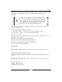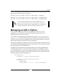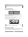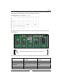
1
www.allitebooks.com
BeagleBone Essentials
Harness the power of the BeagleBone Black to manage
external environments using C, Bash, and Python/PHP
programming
Rodolfo Giometti
BIRMINGHAM - MUMBAI
www.allitebooks.com
BeagleBone Essentials
Copyright © 2015 Packt Publishing
All rights reserved. No part of this book may be reproduced, stored in a retrieval
system, or transmitted in any form or by any means, without the prior written
permission of the publisher, except in the case of brief quotations embedded in
critical articles or reviews.
Every effort has been made in the preparation of this book to ensure the accuracy
of the information presented. However, the information contained in this book is
sold without warranty, either express or implied. Neither the author, nor Packt
Publishing, and its dealers and distributors will be held liable for any damages
caused or alleged to be caused directly or indirectly by this book.
Packt Publishing has endeavored to provide trademark information about all of the
companies and products mentioned in this book by the appropriate use of capitals.
However, Packt Publishing cannot guarantee the accuracy of this information.
First published: May 2015
Production reference: 1260515
Published by Packt Publishing Ltd.
Livery Place
35 Livery Street
Birmingham B3 2PB, UK.
ISBN 978-1-78439-352-6
www.packtpub.com
Cover image by Andrea Dovichi ([email protected])
www.allitebooks.com
Credits
Author
Project Coordinator
Rodolfo Giometti
Kinjal Bari
Reviewers
Proofreaders
Kumar Abhishek
Stephen Copestake
Luca Belluomini
Safis Editing
Richard Bottoms
Indexer
Antonio Tringali
Hemangini Bari
Commissioning Editor
Pramila Balan
Graphics
Sheetal Aute
Acquisition Editor
Subho Gupta
Production Coordinator
Komal Ramchandani
Content Development Editor
Samantha Gonsalves
Cover Work
Komal Ramchandani
Technical Editor
Siddhi Rane
Copy Editor
Rashmi Sawant
www.allitebooks.com
About the Author
Rodolfo Giometti is an engineer, IT specialist, GNU/Linux expert, and software
libre evangelist.
He is the maintainer of LinuxPPS projects (Linux's Pulse Per Second subsystem).
He also actively contributes to the Linux source code community with several
patches and new device drivers for industrial application devices.
He has over 20 years of experience working with x86, ARM, MIPS, and
PowerPC-based platforms.
Now, he is the co-chief at HCE Engineering S.r.l. and a cofounder of the Cosino
Project, which involves new hardware and software systems that are used for quick
prototyping in the industry environment, control automation, and remote monitoring.
I would like to thank my wife, Valentina, for putting up with my
late night writing sessions and my children, Romina and Raffaele,
for reminding me to come back like a child from time to time during
the job. I would also like to extend my deep thanks and gratitude to
the Packt Publishing staff, especially Subho Gupta, who gave me the
opportunity to write this book, Samantha Gonsalves, who helped me
finish this book, and Siddhi Rane for her help in fixing my English.
Many thanks to Armando Genovese for his help in fixing several
electrical and hardware configuration issues. I would also like to
thank Antonio Tringali, Luca Belluomini, and Kumar Abhishek for
their support and efforts in reviewing this book so carefully.
I would also like to thank my mentor, Alessandro Rubini, who
introduced me to the wonderful world of Linux device driver
programming. Many thanks to Richard M. Stallman for the
GNU Project and to Linus Torvalds for the Linux kernel.
Last but not least, I cannot forget to thank my parents, who gave
me my first computer when I was a child and allowed me to be
do what I do today.
www.allitebooks.com
About the Reviewers
Kumar Abhishek is pursuing his integrated bachelor's and master's degree in
electronics and electrical communication engineering at the Indian Institute of
Technology, Kharagpur, India. He has worked with BeagleBoard.org under Google
Summer of Code 2014 to develop BeagleLogic—a logic analyzer using the BeagleBone
Black (for more information, visit https://github.com/abhishek-kakkar/
BeagleLogic/wiki).
Abhishek wrote his first 8051 program when he was 11 years old, and since then,
he has gained experience in a variety of embedded platforms, including 8051, AVR,
STM32, and the BeagleBoard. His favorite toys as a child were his soldering iron and
his computer, as he figured out that he could use them to build more awesome toys.
When he isn't studying or working on his projects, he likes to read books and play
the piano. Abhishek's personal abode on the Internet is "The Embedded Kitchen"
at www.theembeddedkitchen.net.
I am grateful to my parents for nurturing and supporting my activities
alongside academics. My project with BeagleBoard.org under
Google Summer of Code in 2014 has been one of my most awesome
experiences so far, and I'm fortunate to have had the privilege. I am
excited at the opportunities awaiting makers exploring the realm of
small but powerful platforms, such as the BeagleBoard, and I hope
that this book will help in getting you up to speed.
www.allitebooks.com
Luca Belluomini is currently a member of AgustaWestland Technical Direction.
He is in charge of fly control system design, certification, and testing for the AW609
TiltRotor integrated team, working between Italy (headquarters in Cascina Costa)
and USA (Arlington, Texas) to certify the first civil TiltRotor aircraft with
the Federal Aviation Administration.
Earlier in his career at Alenia Aermacchi, he worked for the M346 Master "Lead in
Fighter" project and as a flight control law engineer in the Control Laws R&D team;
he worked to ensure the safety of the flight test activities of the new generation
dedicated to advanced and lead-in fighter trainer / light combat aircraft.
After passing the government exam and being licensed as a professional engineer,
he served as an aeromechanical advisor for the "C27-J Spartan" Alenia Aeronautica
program. He developed one of the few models of wind shear (an aerodynamic
structure that characterizes the terrestrial boundary layer) integrated in a real-time
level A full motion flight simulator to provide tools that are able to design and
improve both take-off and landing procedures.
Luca received a bachelor's degree in aerospace science and a master's degree
in aeronautical science from Università degli Studi di Pisa.
Richard Bottoms is a former US Army Signal Corps NCO and is now
a San Francisco Bay Area-based developer of innovative software and
hardware technologies.
His website design and development work began in the Internet's earliest days,
when he developed one of the country's first media publication websites with
database-backed classified systems for Nuvo Newsweekly, Indianapolis, Indiana
(http://www.nuvo.net/).
He came to California to take up a management role with one of the first firms
built to service Fortune 500 clients at Santa Clara, based US Web, honing some of
the first enterprise-level best practices for the Internet while upgrading the art of
technical sales.
Later, he led the technical sales team for Agniroth, a leading Indian firm offering
offshore support to Silicon Valley firms with their value proposition of a 24-hour
development cycle, allowing nonstop innovations with command and control in
the US.
www.allitebooks.com
Following the dot-com crash, the freedom of open source with low cost, high benefit
technologies such as LAMP (Linux Apache MySQL PHP) allowed him to survive
it by building lightweight, agile support mechanisms for surviving firms evolving
from the breakdown.
In 2007, he took a chance with an untested technology, choosing the unproven
iPhone over the dominant Palm, Inc., and their growing line of Treo mobile phones.
Obviously, this was the right choice as iPhone became the first true smartphone and
its operating system iOS has changed the world.
Later in 2012, recognizing new technologies that were gaining importance, he began
working on the integration of Arduino-compatible microcontrollers projects using
Bluetooth Smart, which was introduced with iPhone 4S.
Now a mature technology, BLE (Bluetooth Low Energy) has led to the well-known
meme the Internet of Things (IoT), which has spawned exciting interconnected smart
technologies that link social networking tools with location-aware smart TCP/IP
addressable devices.
He hopes to make a significant contribution in this field before retiring with his
wonderful wife back in Germany, where he once served as a soldier, before he
found his calling in the field of computing.
Antonio Tringali is an electronic engineer working as a freelancer, who
specializes in automation and remote system control. Most of his work in recent
years is concentrated on automated parking systems and train passenger information
systems. He develops everything a client may throw at him—from the silicon up to
the database—alternating a number of computer languages with the oscilloscope.
He likes to read as much as he can about, well, everything. He likes to write and
teach, so it should not be surprising that he started to know and appreciate Rodolfo
when both were writing for the same leading Italian Linux magazine.
I would like to thank my parents, as they allowed me to fly away to
catch my dreams by the tail. I would also like to thank my wonderful
wife and sons for keeping me anchored to the stuff that really
matters a lot in my life—the best dream you may want to catch.
www.allitebooks.com
www.PacktPub.com
Support files, eBooks, discount offers, and more
For support files and downloads related to your book, please visit
www.PacktPub.com.
Did you know that Packt offers eBook versions of every book published, with PDF
and ePub files available? You can upgrade to the eBook version at www.PacktPub.
com and as a print book customer, you are entitled to a discount on the eBook copy.
Get in touch with us at [email protected] for more details.
At www.PacktPub.com, you can also read a collection of free technical articles,
sign up for a range of free newsletters and receive exclusive discounts and offers
on Packt books and eBooks.
TM
https://www2.packtpub.com/books/subscription/packtlib
Do you need instant solutions to your IT questions? PacktLib is Packt's online digital
book library. Here, you can search, access, and read Packt's entire library of books.
Why subscribe?
• Fully searchable across every book published by Packt
• Copy and paste, print, and bookmark content
• On demand and accessible via a web browser
Free access for Packt account holders
If you have an account with Packt at www.PacktPub.com, you can use this to access
PacktLib today and view 9 entirely free books. Simply use your login credentials for
immediate access.
www.allitebooks.com
Table of Contents
Prefacev
Chapter 1: Installing the Developing System
1
Embedded world terms
A system overview
The first login
Checking out the preloaded tools
The SSH tool
The Apache web server
Setting up a developing system
The LAMP suite
1
2
4
6
6
8
10
13
The compiler
(Re)Installing Debian
The virtual machine
Setting up the host
20
21
24
25
Apache13
PHP
14
MySQL17
The serial connection
The Ethernet connection
25
26
The developing tools
27
Summary28
Chapter 2: Managing the System Console
Getting access to the serial console
Basic system management
File manipulation tools and friends
Package management
Managing the kernel messages
[i]
www.allitebooks.com
29
29
35
35
38
40
Table of Contents
A quick tour of the bootloader
GPIOs management
The environment
Managing the storage devices
The kernel command line
Summary
42
43
44
47
49
50
Chapter 3: Compiling versus Cross-compiling
53
Chapter 4: Quick Programming with Scripts
75
Chapter 5: Device Drivers
97
Native compilation versus cross-compilation
53
Compiling a user-space software package
56
Native compilation
57
Cross-compilation60
Compiling the kernel
63
The Linux kernel
63
Device drivers
70
Summary
73
The GPIO subsystem
The GPIOs on the BeagleBone Black
The sysfs API
Managing an LED in PHP
The LAMP solution
The built-in server solution
Managing an LED in Python
Managing an LED in Bash
Summary
75
76
78
80
80
84
85
88
95
What is a device driver?
97
Char, block, and net devices
99
The modutils
101
Writing our own device driver
103
Summary114
Chapter 6: Serial Ports and TTY Devices
What is a serial port?
The electrical lines
Implementation of serial ports
The serial ports in Linux
The communication parameters
A simple serial echo
[ ii ]
117
117
118
119
120
120
121
Table of Contents
Managing a real device
124
Summary127
Chapter 7: Universal Serial Bus – USB
129
Chapter 8: Inter-integrated Circuit – I2C
145
Chapter 9: Serial Peripheral Interface – SPI
161
Chapter 10: 1-Wire Bus – W1
179
Chapter 11: Useful System Daemons
189
What is the Universal Serial Bus?
The electrical lines
The USB bus in Linux
Acting as a host
Acting as a device
Accessing the raw bus
Summary
129
131
131
133
136
139
143
What is the I2C bus?
145
The electrical lines
146
The I2C bus in Linux
146
Getting access to I2C devices
150
The EEPROM
152
The ADC chip
154
Accessing the bus directly
157
Summary160
What is the SPI bus?
161
The electrical lines
162
The SPI bus in Linux
163
Getting access to the SPI devices
166
Accessing the raw bus
175
Summary178
What is the 1-Wire bus?
179
The electrical lines
181
The 1-Wire bus in Linux
181
Getting access to 1-Wire devices
184
Summary187
What is a daemon?
Useful and ready-to-use daemons
Syslogd
Using in Bash
Using in C
189
191
192
192
193
[ iii ]
Table of Contents
Using in PHP
Using in Python
193
193
Cron
MySQL
194
195
Getting access in Bash
Getting access in C
Getting access in PHP
Getting access in Python
196
198
200
201
Writing a custom daemon
202
Using C
203
Using PHP
204
Using Python
205
Using Bash
206
Summary207
Index209
[ iv ]
Preface
The BeagleBone Black is an embedded system that is able to run an embedded
GNU/Linux distribution as well as a normal (and powerful) distribution, such as
Debian or Ubuntu, and where the user can connect several external peripherals to
it via two dedicated expansion connectors.
By having a powerful distribution capability with an easily expandable embedded
board, the BeagleBone black system is a state-of-the-art device that allows you to
build powerful and versatile monitoring and controlling applications.
Packed with real-world examples, this book will try to fill the gap by showing you
how some peripherals can be connected to the BeagleBone Black, and how you can
get access to them in order to develop your own monitoring and control systems.
After the introductory chapter about how to set up the board from scratch, we'll
take a look at compilation and cross-compilation of both user space and kernel space
applications with some basic debugging techniques. Next, we'll move to high-level
applications, such as daemons, and high-level programming using scripting languages,
such as PHP, Python, and Bash. Finally, we'll see how a system daemon works and
how it can be implemented from scratch using several programming languages.
This book will also explain how several computer peripherals can be connected to
the BeagleBone Black board. We'll present several kinds of devices, such as serial
ports, USB host ports and devices, and SPI/I2C/1-Wire devices. For each peripheral,
we'll see how it can be connected to the BeagleBone Black, and how the developer
can get access to it from the user space, and in some circumstances we'll see some
kernel code too.
The hardware is presented in a generic manner, so no BeagleBone Black capes are
presented in this book! This is because each cape has tons of documentation on the
Internet, and using a generic approach allows you to better understand how the
hardware management works and how to replicate the examples on another
GNU/Linux-based system with a little effort.
[v]
Preface
Accessing all peripherals and writing good monitoring and controlling programs can
both be complex tasks; it's easy to make mistakes early in the development stage that
leads to serious problems in production. Learning the best practices before starting
your project will help you avoid these problems and ensure that your project will be
a success.
What this book covers
Chapter 1, Installing the Developing System, shows you how to use the BeagleBone
Black's on-board operating system and how to (re)install and set up a complete
developing system, based on the Debian distribution, starting from zero.
Chapter 2, Managing the System Console, shows you how a serial console works,
and how you can use it in order to control/monitor the system activities (that is,
monitoring the kernel messages, managing the bootloader, and so on). At the end
of this chapter, a special section will introduce you to some bootloader commands.
Chapter 3, Compiling versus Cross-compiling, show you all the compiling steps in both
kernel and user space to easily add a new driver that is not included in the standard
BeagleBone Black's kernel and/or to recompile a user-space tool, which is not
included in the Debian distribution.
Chapter 4, Quick Programming with Scripts, shows you how to install and use some
common scripting languages in the BeagleBone Black board, and then how to solve
a real problem by writing the solution in each language, in order to show you the
differences between the usage of these languages.
Chapter 5, Device Drivers, shows you a possible implementation of a very simple
driver (by writing a proper kernel module), in order to show you some basics of
the Linux kernel's internals.
Chapter 6, Serial Ports and TTY Devices, discusses the serial ports, which is one
of the most important peripheral classes a computer can have. We'll see how
we can manage them in a Linux system in order to use a real serial device.
Chapter 7, Universal Serial Bus – USB, shows you how the USB bus works, the different
types of USB devices and how they are supported in the BeagleBone Black's kernel.
Simple management examples of real USB device and USB gadget are present.
Chapter 8, Inter-integrated Circuit – I2C, shows you how the I2C bus works, giving
you a panoramic view, as wide as possible, of the most commonly used I2C devices;
we'll discuss an EEPROM, a DAC, and an ADC.
[ vi ]
Preface
Chapter 9, Serial Peripheral Interface – SPI, shows you how the SPI bus works by
presenting you a simple temperature sensor management, as a quite complex
device, such as a mini LCD display.
Chapter 10, 1-Wire Bus – W1, shows you how the 1-Wire bus works by showing you
how to get access to a temperature sensor.
Chapter 11, Useful System Daemons, discusses the Unix daemon by showing you how
an embedded computer developer can use existing daemons or new written ones
in several programming languages.
What you need for this book
The prerequisites required for efficient learning are mentioned in the
following sections.
Software prerequisites
You should have a little knowledge of the software of a non-graphical text editor,
such as vi, emacs, or nano. You can even connect an LCD display, a keyboard, and
a mouse directly to the BeagleBone Black, and then use the graphical interface; in
this book, we assume that you are able to do little modifications to the text files
using a text-only editor.
The host computer, that is, the computer you will use to cross-compile the code
and/or to manage the BeagleBone Black is assumed to run on a GNU/Linux-based
distribution. My host PC is running an Ubuntu 14.04 LTS, but you can use a
Debian-based system too with little modification, or you may use another
GNU/Linux distribution but with a little effort from you, mainly regarding
cross-compiling tools installation. Foreign systems, such as Windows, Mac OS,
or similar ones, are not covered in this book because we should not
use low technology systems to develop the code for high technology systems.
To know how a C compiler works and how to manage a Makefile could help, but
don't worry, all examples start from the very beginning, so even a developer who
is not skilled should be able do the job.
This book will present some kernel programming techniques but these cannot be taken
as a kernel programming course. You need a proper book for such a topic! However, each
example is well-documented and you will find several suggested resources.
Finally, let me add that knowing a visualization system could be useful, especially
in case you wish to set up your own developing host computer.
[ vii ]
Preface
Hardware prerequisites
In this book, all the code is developed for the BeagleBone Black board Revision C,
but you can use an older revision without any issues; in fact, the code is portable,
and it should work on other systems too!
The computer peripherals used in this book are discussed in the section where I got
the hardware and where you can buy it; but of course, you can decide to surf the
Internet in order to find a better and cheaper offer.
You should not have any difficulties connecting the hardware to the BeagleBone Black
presented in this book, since the connections are very few and well documented. They
don't require any particular hardware skills to be performed by you.
Who this book is for
If you are a developer who wants to learn how to use embedded machine learning
capabilities and get access to a GNU/Linux device driver to collect data from a
peripheral or to control a device, this is the book for you. If you have some hardware
or electrical engineering experience and know the basics of C, Bash, and Python/PHP
programming in a Unix environment but desire to learn more about it, then this book
is for you.
Conventions
In this book, you will find a number of text styles that distinguish between different
kinds of information. Here are some examples of these styles and an explanation of
their meaning.
Codes and command lines
Code words in text, database table names, folder names, filenames, file extensions,
pathnames, dummy URLs, user input, and Twitter handles are shown as follows: "To
get the preceding kernel messages, we can use both the dmesg and tail -f /var/
log/kern.log commands."
A block of code is set as follows:
#include <stdio.h>
int main(int argc, char *argv[])
{
[ viii ]
Preface
printf("Hello World!\n");
return 0;
}
When we wish to draw your attention to a particular part of a code block, the
relevant lines or items are set in bold:
#include <stdio.h>
int main(int argc, char *argv[])
{
printf("Hello World!\n");
return 0;
}
Any command line input or output given on the BeagleBone Black is written
as follows:
root@BeagleBone:~# make CFLAGS="-Wall -O2" helloworldcc -Wall -O2
helloworld.c -o helloworld
Any command line input or output given on my host computer as a non-privileged
user is written as follows:
$ tail -f /var/log/kern.log
When I need to give a command as a privileged user (root) on my host computer
the command line input or output is then written as follows:
# /etc/init.d/apache2 restart
The reader should notice that all privileged commands can be executed by a normal
user too by using the sudo command with the form:
$ sudo <command>
So the preceding command can be executed by a normal user as:
$ sudo /etc/init.d/apache2 restart
Kernel and logging messages
On several GNU/Linux distribution a kernel message has the usual form:
Oct 27 10:41:56 hulk kernel: [46692.664196] usb 2-1.1: new high-speed USB
device number 12 using ehci-pci
[ ix ]
Preface
Which is a quite long line for this book, that's why the characters from the start of the
lines till the point where the real information begin are dropped. So, in the preceding
example, the lines output will be reported as follow:
usb 2-1.1: new high-speed USB device number 12 using ehci-pci
Long outputs, repeated or less important lines in a terminal are dropped by replacing
them with three dots ... shown as follows:
output begin
output line 1
output line 2
...
output line 10
output end
File modifications
When the reader should modify a text file, I'm going to use the unified context diff
format since this is a very efficient and compact way to represent a text modification.
This format can be obtained by using the diff command with the -u option argument.
As a simple example, let's consider the following text into file1.old:
This
This
This
...
...
This
is first line
is the second line
is the third line
is the last line
Suppose we have to modify the third line as highlighted in the following snippet:
This
This
This
...
...
This
is first line
is the second line
is the new third line modified by me
is the last line
The reader can easily understand that reporting each time the whole file for a simple
modification it's quite obscure and space consuming, however by using the unified
context diff format the preceding modification can be written as follow:
$ diff -u file1.old file1.new
[x]
Preface
--- file1.old 2015-03-23 14:49:04.354377460 +0100
+++ file1.new 2015-03-23 14:51:57.450373836 +0100
@@ -1,6 +1,6 @@
This is first line
This is the second line
-This is the third line
+This is the new third line modified by me
...
...
This is the last line
Now the modification is very clear and written in a compact form! It starts with a
two-line header where the original file is preceded by --- and the new file is preceded
by +++, then follows one or more change hunks that contain the line differences in the
file. The preceding example has just one hunk where the unchanged lines are preceded
by a space character, while the lines to be added are preceded by a + character and the
lines to be removed are preceded by a - character.
Other conventions
New terms and important words are shown in bold. Words that you see on the screen,
for example, in menus or dialog boxes, appear in the text like this: "If it prints Hello
World, then our code has been executed successfully!"
Warnings or important notes appear in a box like this.
Tips and tricks appear like this.
Reader feedback
Feedback from our readers is always welcome. Let us know what you think about
this book—what you liked or disliked. Reader feedback is important for us as it
helps us develop titles that you will really get the most out of.
To send us general feedback, simply e-mail [email protected], and mention
the book's title in the subject of your message.
If there is a topic that you have expertise in and you are interested in either writing
or contributing to a book, see our author guide at www.packtpub.com/authors.
[ xi ]
www.allitebooks.com
Preface
Customer support
Now that you are the proud owner of a Packt book, we have a number of things to
help you to get the most from your purchase.
Downloading the example code
You can download the example code files from your account at http://www.
packtpub.com for all the Packt Publishing books you have purchased. If you
purchased this book elsewhere, you can visit http://www.packtpub.com/support
and register to have the files e-mailed directly to you.
For this book, the example code can also be downloaded from the author's GitHub
repository at URL https://github.com/giometti/beaglebone_essentials.
Just use the following command to get it at once:
$ git clone https://github.com/giometti/beaglebone_essentials.git
The examples are grouped according to the chapters name so you can easily find
the code during the reading of the book.
Downloading the color images of this book
We also provide you with a PDF file that has color images of the screenshots/
diagrams used in this book. The color images will help you better understand the
changes in the output. You can download this file from https://www.packtpub.
com/sites/default/files/downloads/3526OS_ColoredImages.pdf.
Errata
Although we have taken every care to ensure the accuracy of our content, mistakes
do happen. If you find a mistake in one of our books—maybe a mistake in the text or
the code—we would be grateful if you could report this to us. By doing so, you can
save other readers from frustration and help us improve subsequent versions of this
book. If you find any errata, please report them by visiting http://www.packtpub.
com/submit-errata, selecting your book, clicking on the Errata Submission Form
link, and entering the details of your errata. Once your errata are verified, your
submission will be accepted and the errata will be uploaded to our website or added
to any list of existing errata under the Errata section of that title.
To view the previously submitted errata, go to https://www.packtpub.com/books/
content/support and enter the name of the book in the search field. The required
information will appear under the Errata section.
[ xii ]
Preface
Piracy
Piracy of copyrighted material on the Internet is an ongoing problem across all
media. At Packt, we take the protection of our copyright and licenses very seriously.
If you come across any illegal copies of our works in any form on the Internet, please
provide us with the location address or website name immediately so that we can
pursue a remedy.
Please contact us at [email protected] with a link to the suspected
pirated material.
We appreciate your help in protecting our authors and our ability to bring you
valuable content.
Questions
If you have a problem with any aspect of this book, you can contact us at
[email protected], and we will do our best to address the problem.
[ xiii ]
Installing the Developing
System
In this first chapter, after a short introduction to some common terms of the
embedded programming used in this book, we'll give you a brief overview of
BeagleBone Black's hardware features, how to use the BeagleBone Black's on-board
operating system, and how to (re)install and set up a complete developing system
based on the Debian distribution, starting from zero. At the end of this chapter, we
will give you some hints on how to install a complete host system based on Ubuntu.
Embedded world terms
Before putting our hands on our new board, it is recommended that we
acquaint ourselves with some terms that the user should know in order to
avoid misunderstandings. People who have already worked with some
GNU/Linux and/or embedded systems may skip this part; however, a brief
overview of these preliminary stuff may be useful for everyone. The BeagleBone
Black is a tiny single-board computer that can be embedded into a device, so the
user should be familiar with some terms used in the wonderful world of the
embedded programming.
Term
Description
Target
The target system is the embedded computer that we wish to manage.
Usually, it is an ARM platform, but this is not a fixed rule; in fact,
PowerPC and MIPS are other (less) common platforms. Even the x86
platform (a standard PC) can be an embedded computer too.
[1]
Installing the Developing System
Term
Description
Host
The host system is the computer we will use to manage the target
system. Usually, it is a normal PC (x86 platform) but even other
platforms can be used (for example, years ago, I used a PowerPC-based
computer as a host PC).
Normally, the host system is more powerful than the target one since
it's usually used for heavy compiling tasks that the target cannot do at
all or that it can do but in a time consuming manner.
Serial
console
This is the most important communication port in an embedded system.
Using the serial console, the user has complete control of the system.
Since it's not only indispensable for debugging, but is also the last resort
if, by chance, the operating system files are messed up and the board
refuses to boot.
Without the serial console, the user can still control the system (if
correctly set up) but for the developer/debugger it's a must-have!
Native
compiler
The native compiler is just a-compiler! This is the compiler running on
a machine (host or target) that builds the code for the current machine
(that is, the compiler running on a PC builds the code for the PC like the
one running on an ARM machine that builds the code for ARM itself).
Crosscompiler
Strictly speaking, the cross-compiler is just a compiler that builds the
code for a foreign platform (that is, a cross-compiler can run on a PC
in order to generate binaries for an ARM platform), but usually, by
using this term, the embedded developers also mean the complete
compilation suite, that is: the compiler, linker, binutils, libc, and so on.
A system overview
The BeagleBone Black is a complete computer despite its dimensions. In fact, it's a
little bigger than a credit card yet power packed.
The main hardware key features are as follows:
Part
Specification
Processor
ARM processor: Sitara AM3358 @ 1 Ghz with 3D engine
SDRAM memory
512 MB DDR3 @800 Mhz
On-board flash
4 GB, 8-bit eMMC
USB 2.0 ports
1 device
1 host
Serial port
UART0 via 6 pin 3.3 V TTL connector
Ethernet
10/100 via RJ45 connector
[2]
Chapter 1
Part
Specification
SD/MMC
MicroSD 3.3 V slot
Video out
16b HDMI 1280 x 1024
Audio out
Stereo via HDMI interface
LED indicators
• 1 for power
• 2 on the Ethernet port
• 4 user controllable
Expansion
connectors
• Power 5 V, 3.3 V, VDD ADC (1.8 V)
• 69 (max) GPIOs 3.3 V
• SPI, I2C, LCD, GPMC, MMC1-2, CAN
• 7 ADC (1.8 V max)
• 4 timers
• 4 serial ports
• 3 PWMs
The following image shows a top view of the BeagleBone Black, where we can see
some interesting things:
• The connector J1 can be used to access the serial console (this concept
will be explained in detail in the Getting access to the serial console section
of Chapter 2, Managing the System Console).
• The Ethernet connector.
• The two expansion connectors P8 and P9, where we can connect
the dedicated extension boards and/or custom peripherals (these
connectors will be explained in detail in the next chapters).
• The reset button can be used to reset the board. The power button
can be used to turn on/off the board.
[3]
Installing the Developing System
From the preceding image, we can see that the BeagleBone Black doesn't look like
a PC, but it can act as a PC! The BeagleBone Black is a fully functional single-board
computer and can be readily used as a PC if required by connecting a monitor to the
HDMI port and attaching a USB keyboard and mouse through a USB hub. However,
it is more suited to embedded applications, where it can act as more than a PC due
its expansion connectors, and we can stack up to four expansion boards (named
capes) that are useful for several purposes.
In this book, we'll see how we can manage (and reinstall) a complete Debian
distribution that allows us to have a wide set of ready-to-run software packages, as
a normal PC may have (in fact, the Debian ARM version is equivalent to the Debian
x86 version). Then, we'll see how we can use the expansion connectors to connect to
the board. Several peripherals are used to monitor/control the external environment.
The first login
Once we get our new BeagleBone Black in front of us, we just have a board and a USB
cable, so the only thing to do is to connect one end of the USB cable to the BeagleBone
Black's mini USB connector and the other end to our PC's USB host port:
If everything works well, we should see the BeagleBone Black's user LEDs blinking
(on the board, these LEDs are labeled as USER LEDS) and after a while, on the host
PC, we should get some kernel messages as follows:
usb 2-1.1: new high-speed USB device number 12 using ehci-pci
usb 2-1.1: New USB device found, idVendor=1d6b, idProduct=0104
usb 2-1.1: New USB device strings: Mfr=2, Product=3, SerialNumber=4
usb 2-1.1: Product: BeagleBoneBlack
usb 2-1.1: Manufacturer: Circuitco
[4]
Chapter 1
usb 2-1.1: SerialNumber: C0-3214BBBK0716
rndis_host 2-1.1:1.0 eth0: register 'rndis_host' at usb-0000:00:1d.0-1.1,
RNDIS device, 78:a5:04:ca:cb:00
cdc_acm 2-1.1:1.2: This device cannot do calls on its own. It is not a
modem.
cdc_acm 2-1.1:1.2: ttyACM0: USB ACM device
I'm using an Ubuntu 14.04 LTS-based system as a host PC.
To get the preceding kernel messages, we can use both the
dmesg and tail -f /var/log/kern.log commands.
This behavior means that the BeagleBone Black is working correctly, so let's first
log in to the system.
Let's take a look at the preceding kernel messages. We will notice the following
two lines:
cdc_acm 2-1.1:1.2: This device cannot do calls on its own. It is not a
modem.
cdc_acm 2-1.1:1.2: ttyACM0: USB ACM device
The serial device ttyACM0 can be used to get access to the BeagleBone Black's internal
system. To do so, we can use a terminal emulator; usually, I use minicom, but you can
use your preferred tool. In case of minicom, the following command line is used:
$ minicom -o -D /dev/ttyACM0
You must now verify that the serial port setup is 115200,8N1 without the hardware
and software flow control (in minicom, these settings can be checked using the Ctrl
+A + O key sequence, and then selecting the entry in the Serial port setup menu).
Now, if we press the Enter key, we get the following string:
Password:
Nothing to worry about, just hit the Enter key again and then enter the string root
when the board asks for an user account as reported as follows:
BeagleBone login:
No password is needed here. The console then displays the last login time and the
version. It will look something like this:
Last login: Wed Apr 23 20:20:54 UTC 2014 on ttyGS0
Linux BeagleBone 3.8.13-bone47 #1 SMP Fri Apr 11 01:36:09 UTC 2014 armv7l
The programs included with the Debian GNU/Linux system are free software;
[5]
Installing the Developing System
the exact distribution terms for each program are described in the
individual files in /usr/share/doc/*/copyright.
Debian GNU/Linux comes with ABSOLUTELY NO WARRANTY, to the extent
permitted by applicable law.
root@BeagleBone:~#
Great! We just did our first login!
Checking out the preloaded tools
Now that we are logged into the system, it's time to take a look at the preloaded
tools. In the next section, we're going to install all the missing software that a good
developing system needs.
The SSH tool
Now we should verify that the Secure Shell (SSH) tool is functional. The Secure
Shell, sometimes known as Secure Socket Shell, is a Unix-based command interface
for securely getting access to a remote computer. It was designed to replace the
insecure telnet. To test it on the target serial console, we can use the ifconfig
command to check the network settings:
root@BeagleBone:~# ifconfig
Then, the following message is displayed:
eth0
Link encap:Ethernet
HWaddr 78:a5:04:ca:c9:fe
UP BROADCAST MULTICAST
MTU:1500
Metric:1
RX packets:0 errors:0 dropped:0 overruns:0 frame:0
TX packets:0 errors:0 dropped:0 overruns:0 carrier:0
collisions:0 txqueuelen:1000
RX bytes:0 (0.0 B)
TX bytes:0 (0.0 B)
Interrupt:40
lo
Link encap:Local Loopback
inet addr:127.0.0.1
Mask:255.0.0.0
inet6 addr: ::1/128 Scope:Host
UP LOOPBACK RUNNING
MTU:65536
[6]
Metric:1
Chapter 1
RX packets:0 errors:0 dropped:0 overruns:0 frame:0
TX packets:0 errors:0 dropped:0 overruns:0 carrier:0
collisions:0 txqueuelen:0
RX bytes:0 (0.0 B)
usb0
TX bytes:0 (0.0 B)
Link encap:Ethernet
HWaddr 96:66:68:88:3b:fa
inet addr:192.168.7.2
Bcast:192.168.7.3
Mask:255.255.255.252
inet6 addr: fe80::9466:68ff:fe88:3bfa/64 Scope:Link
UP BROADCAST RUNNING MULTICAST
MTU:1500
Metric:1
RX packets:3376 errors:0 dropped:0 overruns:0 frame:0
TX packets:41 errors:0 dropped:0 overruns:0 carrier:0
collisions:0 txqueuelen:1000
RX bytes:926304 (904.5 KiB)
TX bytes:10306 (10.0 KiB)
We can use the usb0 device (which is a virtual Ethernet running on the USB cable).
First, we should check whether the corresponding Ethernet device has been created
on the host using the same command:
$ ifconfig
The output of the command is as follows:
eth1
Link encap:Ethernet
HWaddr bc:ae:c5:20:36:80
UP BROADCAST MULTICAST
MTU:1500
Metric:1
RX packets:0 errors:0 dropped:0 overruns:0 frame:0
TX packets:0 errors:0 dropped:0 overruns:0 carrier:0
collisions:0 txqueuelen:1000
RX bytes:0 (0.0 B)
eth4
TX bytes:0 (0.0 B)
Link encap:Ethernet
HWaddr 78:a5:04:ca:cb:00
inet addr:192.168.7.1
Bcast:192.168.7.3
Mask:255.255.255.252
inet6 addr: fe80::7aa5:4ff:feca:cb00/64 Scope:Link
UP BROADCAST RUNNING MULTICAST
MTU:1500
Metric:1
RX packets:112 errors:0 dropped:0 overruns:0 frame:0
TX packets:3483 errors:0 dropped:0 overruns:0 carrier:0
collisions:0 txqueuelen:1000
RX bytes:17031 (17.0 KB)
TX bytes:1143213 (1.1 MB)
[7]
www.allitebooks.com
Installing the Developing System
Note that I dropped all the network devices that are not named ethX
(for example, the lo device, wlanX, and so on.).We can notice that the
eth4 device, which owns the IP address 192.168.7.1, is the one we
are looking for. Because of this fact, its IP address is in the same subnet
of the BeagleBone Black's usb0 device mentioned earlier. So, let's get
connected via SSH to our board with the following command:
$ ssh [email protected]
The authenticity of host '192.168.7.2 (192.168.7.2)' can't be
established.
ECDSA key fingerprint is b1:a9:84:39:71:99:a3:af:9e:ba:26:d5:e6:77:03:08.
Are you sure you want to continue connecting (yes/no)? yes
Warning: Permanently added '192.168.7.2' (ECDSA) to the list of known
hosts.
Debian GNU/Linux 7
BeagleBoard.org BeagleBone Debian Image 2014-04-23
Support/FAQ: http://elinux.org/Beagleboard:BeagleBoneBlack_Debian
Last login: Thu Apr 24 21:20:09 2014 from hulk.local
root@BeagleBone:~#
Great! We can now be rest assured that the SSH is working.
We have to answer yes when the ssh command asks us if we are
sure we want to continue.
The Apache web server
In the Internet era, a web interface is a must-have, and the easy way to have one
is to install a LAMP (Linux-Apache-MySQL-PHP) suite.
By default, the preloaded Debian image has the Apache web server preinstalled,
so if we point our web browser to the host at the address 192.168.7.2 and port
8080, we should get something like this:
[8]
Chapter 1
However, we must not forget to mention the port 8080 specification in the URL
(the correct form is 192.168.7.2:8080), or we'll get a different output related to
the Bone101 service, as shown in the following screenshot:
[9]
Installing the Developing System
The Bone101 service is something similar to the Arduino IDE, which is a high-level
programming environment, where beginners can try simple programs using an
integrated IDE and a dedicated JavaScript library.
You can take a look at this system using the tutorial at http://beagleboard.org/
support/bone101. However, we are going to disable this service in the next section
because it's not useful to better understand how the computer peripherals can be
connected to and managed by the BeagleBone Black, and also, in order to get a
standard LAMP suite, we need port 80 to be free.
Setting up a developing system
Ok, first of all, we should set up the networking settings, since we are going to
download a lot of software packages. The Ethernet cable should be plugged into
the BeagleBone Black's Ethernet connector and the other end should be connected
to the LAN switch. If the connection works, we should see the following line in the
BeagleBone Black's kernel messages:
libphy: 4a101000.mdio:00 - Link is Up - 100/Full
Let me remind you that you can use either the tail -f /var/log/
kern.log or dmesg command to see the kernel messages.
We can avoid using an Ethernet connection with a network trick; in fact,
the host PC can be used as a gateway, for the BeagleBone Black, that
can access the Internet using the USB cable. In the host, we can use the
following commands:
# iptables --table nat --append POSTROUTING --outinterface eth1 -j MASQUERADE
# iptables --append FORWARD --in-interface eth4 -j
ACCEPT
# echo 1 >> /proc/sys/net/ipv4/ip_forward
Then, on the BeagleBone Black, we can set the gateway through the USB
cable using the following command:
root@beaglebone:~# route add default gw 192.168.7.1
The eth1 device is the preferred Internet connection on the host
system, while the eth4 device is the BeagleBone Black's device as
viewed on the host system, as already seen earlier.
[ 10 ]
Chapter 1
If we have a DHCP server installed in our LAN, the eth0 interface should
automatically display an IP address. Here is what I get on my LAN:
root@BeagleBone:~# ifconfig eth0
eth0
Link encap:Ethernet
HWaddr 78:a5:04:ca:c9:fe
inet addr:192.168.32.30
Bcast:192.168.32.255 Mask:255.255.255.0
inet6 addr: fe80::7aa5:4ff:feca:c9fe/64 Scope:Link
UP BROADCAST RUNNING MULTICAST
MTU:1500
Metric:1
RX packets:143 errors:0 dropped:0 overruns:0 frame:0
TX packets:136 errors:0 dropped:0 overruns:0 carrier:0
collisions:0 txqueuelen:1000
RX bytes:23623 (23.0 KiB)
TX bytes:19576 (19.1 KiB)
Interrupt:40
However, if the DHCP server is up and running, but for some mystic reasons,
this magic doesn't happen, we can force it using the following command:
root@BeagleBone:~# dhclient eth0
On the other hand, if the DHCP server is not working at all, we can use a static
configuration by altering the /etc/network/interfaces file by adding the
following lines:
iface eth0 inet static
address 192.168.32.30
netmask 255.255.255.0
network 192.168.32.0
gateway 192.168.32.8
Next, we need to add the DNS settings to the /etc/resolv.conf file by adding
the following lines:
nameserver 94.249.192.104
nameserver 8.8.8.8
Note that the IP/DHCP addresses mentioned in the commands are user
specific. You should change them so that they match your settings.
[ 11 ]
Installing the Developing System
When all the modifications are in place, we should restart the networking activities:
root@BeagleBone:~# /etc/init.d/networking restart
Now we are ready to verify that the network settings are set correctly by trying to
update the software repositories with the following command:
root@BeagleBone:~# aptitude update
Get: 1 http://security.debian.org wheezy/updates Release.gpg [836 B]
Get: 2 http://ftp.us.debian.org wheezy Release.gpg [1,655 B]
Get: 3 http://debian.beagleboard.org wheezy-bbb Release.gpg [490 B]
Get: 4 http://security.debian.org wheezy/updates Release [102 kB]
...
Get: 38 http://ftp.us.debian.org wheezy-updates/main 2014-06-16-2054.31.pdiff [5
01 B]
Fetched 20.1 MB in 35s (561 kB/s)
Current status: 78 updates [+78], 2 new [+2].
There is 1 newly obsolete package: libmozjs10d
Here, the system tells you that just one package is obsolete, and there are some new
packages to be installed, so you can either leave all of them untouched or decide to
upgrade everything. In the latter case, we can use the following command:
root@BeagleBone:~# aptitude upgrade
The following packages will be upgraded:
acpi-support-base apache2 apache2-mpm-worker apache2-utils apache2.2-bin
apache2.2-common apt apt-utils base-files bash BeagleBone bind9-host curl
dbus dbus-x11 dpkg dpkg-dev file gnupg gpgv libapt-inst1.5 libapt-pkg4.12
libavcodec-dev libavcodec53 libavformat-dev libavformat53 libavutil-dev
libavutil51 libbind9-80 libc-bin libc-dev-bin libc6 libc6:armel libc6-dev
libcups2 libcurl3 libcurl3-gnutls libdbus-1-3 libdbus-1-dev libdns88
libdpkg-perl libgnutls26 libgssapi-krb5-2 libisc84 libisccc80 libisccfg82
libjpeg-progs libjpeg8 libjpeg8-dev libk5crypto3 libkrb5-3
libkrb5support0 liblcms2-2 liblwres80 libmagic1 libnspr4 libnss3
libsmbclient libsoup-gnome2.4-1 libsoup2.4-1 libssl-dev libssl-doc
libssl1.0.0 libswscale-dev libswscale2 libwbclient0 libxfont1 libxml2
libxml2-dev libxml2-utils linux-libc-dev locales multiarch-support
openssh-client openssh-server openssl rsyslog tzdata
The following packages are RECOMMENDED but will NOT be installed:
bash-completion gnupg-curl gnupg-curl:armel krb5-locales
[ 12 ]
Chapter 1
78 packages upgraded, 0 newly installed, 0 to remove and 0 not upgraded.
Need to get 53.2 MB of archives. After unpacking 159 kB will be freed.
Do you want to continue? [Y/n/?]
A lot to do here. For the moment, I decide to leave the system untouched. So, I just
answer no by typing n.
The LAMP suite
Now let's see how to set up a proper LAMP suite.
Apache
First of all, we should drop the Bone101 service in order to free port 80, which is the
World Wide Web's default port:
root@BeagleBone:~# systemctl stop bonescript.socket
root@BeagleBone:~# systemctl disable bonescript.socket
rm '/etc/systemd/system/sockets.target.wants/bonescript.socket'
Ok. Now, to test whether port 80 is really free, we type the following command and
echo it to be sure of its status:
root@BeagleBone:~# netstat -pln | grep ':80\>' || echo "OK."
OK.
Now, we can switch the Apache web server from port 8080 to port 80 by altering
the first lines of the /etc/apache2/sites-enabled/000-default file as follows:
--- 000-default.orig 2014-04-23 20:21:56.619140638 +0000
+++ 000-default 2014-10-10 20:00:21.752090984 +0000
@@ -1,4 +1,4 @@
-<VirtualHost *:8080>
+<VirtualHost *:80>
ServerAdmin webmaster@localhost
DocumentRoot /var/www
Then, replace all the 8080 occurrences with the string 80 in the /etc/apache2/
ports.conf file as follows:
--- ports.conf.orig 2014-04-23 20:23:46.623046902 +0000
+++ ports.conf 2014-04-23 20:24:01.580078153 +0000
@@ -5,8 +5,8 @@
# Debian etch). See /usr/share/doc/apache2.2-common/NEWS.Debian.gz
and
[ 13 ]
Installing the Developing System
# README.Debian.gz
-NameVirtualHost *:80
-Listen 80
+NameVirtualHost *:8080
+Listen 8080
<IfModule mod_ssl.c>
# If you add NameVirtualHost *:443 here, you will also have to
change
Now that all the modifications are done, we will now restart the server. To do so,
we will use the following command:
root@BeagleBone:~# /etc/init.d/apache2 restart
[....] Restarting apache2 (via systemctl): apache2.service. ok
Once the server has been restarted, we will check whether the server is in the
listening state. To do this, we will type the following command:
root@BeagleBone:~# netstat -pln | grep ':80\>'
tcp6
0
0 :::80
:::*
LISTEN
2367/apache2
Ok, we did it! You can now repoint your browser to the default port 80 to verify
that everything is working correctly.
PHP
Now, we can verify that the Apache PHP support is working by adding a simple
PHP file to the DocumentRoot directory /var/www, as specified in the /etc/apache2/
sites-enabled/000-default configuration file:
root@BeagleBone:~# cd /var/www/
root@BeagleBone:/var/www# cat > test.php <<EOF
<?php
phpinfo();
?>
EOF
The <<EOF trick used in the preceding command is often used when
we need to supply one or more commands to a program directly to its
standard input line (stdin). Using such a syntax, we tell the Bash shell
to send the lines to the command itself and the line that holds the EOF
characters directly to stdin of the executed command.
[ 14 ]
Chapter 1
Now, if we point the browser to the URL http://192.168.7.2/test.php, we'll
most probably get a blank page. This means that Apache lacks the PHP support,
so let's install it:
root@BeagleBone:~# aptitude install libapache2-mod-php5 apache2-mpmworker- apache2The following NEW packages will be installed:
apache2-mpm-prefork{a} libapache2-mod-php5 libonig2{a} libqdbm14{a}
lsof{a} php5-cli{a} php5-common{a}
The following packages will be REMOVED:
apache2 apache2-mpm-worker
The following packages will be upgraded:
apache2.2-bin apache2.2-common
2 packages upgraded, 7 newly installed, 2 to remove and 74 not upgraded.
Need to get 6,748 kB of archives. After unpacking 14.4 MB will be used.
Do you want to continue? [Y/n/?]
Don't forget the sign—after apache2-mpm-worker and apache2
because this means that we want to uninstall these packages, as they
are incompatible with the apache2-mpm-prefork package.
You may discover the difference between the apache2-mpm-worker
and apache2-mpm-prefork packages by surfing the net.
Let's press y and proceed:
Get: 1 http://ftp.us.debian.org/debian/ wheezy/main lsof armhf 4.86+dfsg-1 [315
kB]
Get: 2 http://security.debian.org/ wheezy/updates/main php5-common armhf 5.4.4-1
4+deb7u14 [589 kB]...
Setting up php5-common (5.4.4-14+deb7u14) ...
Setting up apache2-mpm-prefork (2.2.22-13+deb7u3) ...
[....] Starting apache2 (via systemctl): apache2.service. ok
Setting up libonig2 (5.9.1-1) ...
Setting up libqdbm14 (1.8.78-2) ...
Setting up libapache2-mod-php5 (5.4.4-14+deb7u14) ...
Creating config file /etc/php5/apache2/php.ini with new version
[....] Restarting apache2 (via systemctl): apache2.service. ok
Setting up php5-cli (5.4.4-14+deb7u14) ...
[ 15 ]
Installing the Developing System
We can update the alternatives using /usr/bin/php5 to provide /usr/bin/php
(php) in auto mode. Note that during this procedure, we may get a lot of errors,
which are as follows:
insserv: Starting led_aging.sh depends on rc.local and therefore on system facil
ity `$all' which can not be true!
insserv: Max recursions depth 99 reached
insserv:
loop involving service udhcpd at depth 2
insserv: There is a loop between service rc.local and mountall-bootclean if star
ted...
dpkg: error processing apache2-mpm-worker (--configure):
dependency problems - leaving unconfigured
Errors were encountered while processing:
apache2.2-common
apache2
apache2-mpm-worker
Don't panic! Just replace the /etc/init.d/led_aging.sh file with the
following code:
#!/bin/sh -e
### BEGIN INIT INFO
# Provides:
# Required-Start:
# Required-Stop:
# Default-Start:
# Default-Stop:
# Short-Description:
# Description:
### END INIT INFO
led_aging.sh
$local_fs
$local_fs
2 3 4 5
0 1 6
Start LED aging
Starts LED aging (whatever that is)
x=$(/bin/ps -ef | /bin/grep "[l]ed_acc")
if [ ! -n "$x" -a -x /usr/bin/led_acc ]; then
/usr/bin/led_acc &
fi
Downloading the example code
You can download the example code files from your account at
http://www.packtpub.com for all the Packt Publishing books
you have purchased. If you purchased this book elsewhere, you can
visit http://www.packtpub.com/support and register to have
the files e-mailed directly to you.
[ 16 ]
Chapter 1
Ok. Now we can test the PHP support by reloading the URL http://192.168.7.2/
test.php. The output should be something similar to the following screenshot:
MySQL
Now the last step is to add the MySQL database server and the corresponding
PHP support.
Installing the MySQL server is quite easy:
root@BeagleBone:~# aptitude install mysql-server mysql-client
[ 17 ]
www.allitebooks.com
Installing the Developing System
Type the preceding command and proceed with the installation as mentioned earlier,
and when the system asks for an administrative password for the database of the
root user (don't confuse this MySQL user with the system's root user!), we should
create one.
It may happen that some strange characters are displayed on the serial
terminal; don't panic, it's just a display issue. We can ignore them and
enter the desired root's password.
Also, note that you can install the mysql-client packet too to be able
to manage the database settings from the command line.
When finished, the system should display this:
Setting up libhtml-template-perl (2.91-1) ...
Setting up mysql-client (5.5.38-0+wheezy1) ...
Setting up mysql-server (5.5.38-0+wheezy1) ...
This means that the MySQL server is up and running. We can easily test it by
running the following command, again using the preceding <<EOF trick:
root@BeagleBone:~# mysql -u root -p <<EOF
show databases;
EOF
The system will ask for the database's root password to be inserted during the
installation by showing the following line:
Enter password:
Then, if the password is correct, the output will be as follows:
Database
information_schema
mysql
performance_schema
If we get the preceding output, it means that we did it! This means that the
installation was successful. However, the PHP still lacks the MySQL support;
in fact, if we add the following code to the mysql_test.php file in the /var/www
directory (as done earlier for the test.php file):
<?php
# Check the PHP's MySQL support
[ 18 ]
Chapter 1
if (!function_exists("mysql_connect"))
die("MySQL support missing!");
# Get connect with the MySQL server.
# Don't forget to replace the following string "ROOTPASS" with
# the database's root password you choose during the installation!!!
$connect = mysql_connect("localhost", "root", "ROOTPASS")
or die("Unable to Connect");
mysql_select_db("information_schema")
or die("Could not open the db");
# Do a simple query
$showtablequery = "SHOW TABLES FROM information_schema";
$query_result = mysql_query($showtablequery);
# Let's display the result!
while($row = mysql_fetch_array($query_result))
echo $row[0] . " ";
?>
Then, pointing the web browser to the URL http://192.168.32.30:8080/mysql_
test.php, we will see an error message as follows:
MySQL support missing!
So, to install PHP's MySQL support, use the following command:
root@BeagleBone:~# aptitude install php5-mysql
If we try reloading the preceding URL, we will not see the error messages anymore
but the following text:
CHARACTER_SETS COLLATIONS COLLATION_CHARACTER_SET_APPLICABILITY COLUMNS
COLUMN_PRIVILEGES ENGINES EVENTS FILES GLOBAL_STATUS GLOBAL_VARIABLES
KEY_COLUMN_USAGE PARAMETERS PARTITIONS PLUGINS PROCESSLIST PROFILING
REFERENTIAL_CONSTRAINTS ROUTINES SCHEMATA SCHEMA_PRIVILEGES SESSION_
STATUS SESSION_VARIABLES STATISTICS TABLES TABLESPACES TABLE_CONSTRAINTS
TABLE_PRIVILEGES TRIGGERS USER_PRIVILEGES VIEWS INNODB_BUFFER_PAGE
INNODB_TRX INNODB_BUFFER_POOL_STATS INNODB_LOCK_WAITS INNODB_CMPMEM
INNODB_CMP INNODB_LOCKS INNODB_CMPMEM_RESET INNODB_CMP_RESET INNODB_
BUFFER_PAGE_LRU
[ 19 ]
Installing the Developing System
The compiler
Just a few years ago, the native compilation of programs on the target embedded
system was previously unheard of, but the latest CPUs are now really powerful and
both the RAM and storage (Flash, MMC, and so on.) memories are quite large to
support native compilations. The BeagleBone hardware is capable of handling native
compilations with ease although in terms of compilation time, it is more practical to
cross-compile for larger projects or use the kernel (that's why we will show you how
to install a cross-compiler on the host PC in the last section of this chapter).
The command to install the GGC suite is as follows:
root@BeagleBone:~# aptitude install gcc make
On my system, the preceding packages are already installed; in this
case, the preceding command will give an answer to us as follows:
No packages will be installed, upgraded, or removed.
0 packages upgraded, 0 newly installed, 0 to remove and
74 not upgraded.
Need to get 0 B of archives. After unpacking 0 B will
be used.
To check whether the compiler is working, we can consider compiling the classic
Hello World C program. To do so, just insert the following code into a file called
helloworld.c:
#include <stdio.h>
int main(int argc, char *argv[])
{
printf("Hello World!\n");
return 0;
}
Now we can compile it using the following command:
root@BeagleBone:~# make CFLAGS="-Wall -O2" helloworld
cc -Wall -O2
helloworld.c
-o helloworld
To execute the new program, type the following line:
root@BeagleBone:~# ./helloworld
Hello World! If it prints Hello World, then our code has been executed successfully!
[ 20 ]
Chapter 1
(Re)Installing Debian
The on-board system is a complete ready-to-use Debian distribution; however, it may
happen that we may need another image (maybe during some developing stages)
or just for backup purposes (just in case, the default image is corrupted for some
reason). So, it's important to see how we can install an alternate image on our board.
There are many ways to install a Debian OS on our BeagleBone Black. I'm going to
use the simplest and quickest one using a prebuild image to be put on a microSD.
This solution has the advantage that by simply removing the microSD from the
system, the board will boot with the original default image.
A similar procedure may be used to install a different OS too.
Note that the microSD should be a class 10 and have at least 4
GB storage space.
The first step is to download the image to a working directory on the host machine.
We have several resources on the Internet, but I chose the one at http://ynezz.
ibawizard.net/beagleboard/wheezy/.
The command to download the file is as follows:
$ wget http://ynezz.ibawizard.net/beagleboard/wheezy/debian-7.6-consolearmhf-2014-08-13.tar.xz
By the time you read this, new versions could be available or the current one
could be missing. Then, you should verify the available versions in case of errors
while downloading the rootfs image used earlier. Next, unzip it, and then enter
the newly created directory:
$ tar xf debian-7.6-console-armhf-2014-08-13.tar.xz
$ cd debian-7.6-console-armhf-2014-08-13
We are now ready to build our microSD.
This is a very important step! Follow the steps carefully or you
may damage your host system.
The command to build the microSD is as follows:
# ./setup_sdcard.sh --mmc /dev/sdX --dtb BeagleBone
[ 21 ]
Installing the Developing System
Here the /dev/sdX device must be chosen carefully. The best way to do so is using
the tail command on the host in order to watch the kernel messages while we insert
the microSD into our host PC:
$ tail -f /var/log/kern.log
In this situation, an usual kernel activity should be something like this:
usb 2-1.1: new high-speed USB device number 18 using ehci-pci
usb 2-1.1: New USB device found, idVendor=058f, idProduct=6387
usb 2-1.1: New USB device strings: Mfr=1, Product=2, SerialNumber=3
usb 2-1.1: Product: Miss Storage
usb 2-1.1: Manufacturer: Generic
usb 2-1.1: SerialNumber: 9B4B5BCC
usb-storage 2-1.1:1.0: USB Mass Storage device detected
scsi13 : usb-storage 2-1.1:1.0
scsi 13:0:0:0: Direct-Access
Generic
FIash Disk
8.07 PQ: 0 ANSI: 2
sd 13:0:0:0: Attached scsi generic sg3 type 0
sd 13:0:0:0: [sdd] 15663104 512-byte logical blocks: (8.01 GB/7.46 GiB)
sd 13:0:0:0: [sdd] Write Protect is off
sd 13:0:0:0: [sdd] Mode Sense: 03 00 00 00
sd 13:0:0:0: [sdd] No Caching mode page found
sd 13:0:0:0: [sdd] Assuming drive cache: write through
sd 13:0:0:0: [sdd] No Caching mode page found
sd 13:0:0:0: [sdd] Assuming drive cache: write through
sdd: sdd1
sd 13:0:0:0: [sdd] No Caching mode page found
sd 13:0:0:0: [sdd] Assuming drive cache: write through
sd 13:0:0:0: [sdd] Attached SCSI removable disk
FAT-fs (sdd1): Volume was not properly unmounted. Some data may be corrupt.
Please run fsck.
If we take a look at the preceding messages, it is quite clear that on my PC, the device
used is /dev/sdd. In fact, these lines tell me that the newly attached SCSI device
(the microSD) has been assigned to the sdd device.
[ 22 ]
Chapter 1
Depending on our system configuration, we may discover that the
right device to use is /dev/sdb, /dev/sdc, and so on or even a
device named as /dev/mmcblk0. In this last case, our host PC is using
a MMC device instead of a USB adapter to manage the SD or microSD
slot of the PC. In this special situation, the kernel messages look like:
mmc0: cannot verify signal voltage switch
mmc0: new ultra high speed SDR50 SDHC card at address
0007
mmcblk0: mmc0:0007 SD4GB 3.70 GiB
mmcblk0: p1
Once the right device has been discovered, we can proceed with the
microSD creation:
# ./setup_sdcard.sh --mmc /dev/sdd --dtb BeagleBone
The system will display a complete disk configuration asking for user confirmation;
if we are sure about what we are doing, we've simply to answer yes and go on.
At the end, we should see something like this:
Debug: image has: v3.16.0-armv7-x4
Debug: image has: v3.16.0-armv7-lpae-x2
Debug: image has: v3.8.13-bone63
Debug: using: v3.8.13-bone63
Finished populating rootfs Partition
----------------------------setup_sdcard.sh script complete
----------------------------The default user:password for this image:
debian:temppwd
-----------------------------
Well, now we can remove the microSD from the host PC and put it in our BeagleBone
Black. If everything has been done correctly, then after we reboot, we can log in to our
new Debian system in the same way as we did during our first login earlier:
$ minicom -o -D /dev/ttyACM0
[ 23 ]
Installing the Developing System
Note that this time, we have to wait a bit longer that the normal boot
due to some configuration issues of this Debian image, which can
delay the booting time. This fact will be more clear in the following
chapter, where we will be able to see the serial console messages.
Then, as reported, at the end of the microSD creation stage, we must supply
the debian user with the temppwd password (don't worry if no login prompt is
displayed), as shown in the following code:
debian
Password:
Last login: Wed Apr 23 20:21:01 UTC 2014 on ttyGS0
Linux BeagleBone 3.8.13-bone47 #1 SMP Fri Apr 11 01:36:09 UTC 2014 armv7l
The programs included with the Debian GNU/Linux system are free software;
the exact distribution terms for each program are described in the
individual files in /usr/share/doc/*/copyright.
Debian GNU/Linux comes with ABSOLUTELY NO WARRANTY, to the extent
permitted by applicable law.
debian@BeagleBone:~$
The virtual machine
As stated at the beginning of this book, as a host system, I'm using a normal PC
running Ubuntu 14.04 LTS distribution. Those who may wish to use another GNU/
Linux-based OS can use most of the commands I'm going to use in the next chapter
without any modifications (or with just a few differences, these can be replaced with
a little effort). However, those who still insist on using a Windows- or Mac OS-based
host system may have some troubles in following what I do, that's why I decided
to write this little section/tutorial to help these people to install a GNU/Linux host
system on their computers.
The trick to do our job is quite simple: we should use a virtual machine! Here, it is
not so important to know which visualization system is used (my preference is for
VirtualBox), the important thing is to install a GNU/Linux-based OS.
I will skip the instructions on how to install a new OS on a virtual machine since
this is not the purpose of this book and because this operation is quite simple.
[ 24 ]
Chapter 1
Setting up the host
Ok, now that our new GNU/Linux OS is running on our new virtual machine, we
need to make some adjustments in order to use it as a real host PC.
All the commands are for Ubuntu 14.04 LTS. You should use the proper
commands if you decide to install a different GNU/Linux distribution.
First of all, let's check the networking settings; we should verify that our system can
access the Internet so that we can install all the needed tools.
The serial connection
To check whether we can get connected to our BeagleBone via the emulated serial
port, as we did during our first login, we need to install the minicom tool:
bbb@bbb-VirtualBox:~$ sudo apt-get install minicom
After the installation is completed, verify that the virtual machine is connected to
the USB host port, where the BeagleBone Black is connected by checking the kernel
messages as done earlier:
cdc_acm 1-1:1.2: ttyACM0: USB ACM device
You should verify that the USB device corresponding to the BeagleBone Black
is connected to the virtual machine. This action depends on the virtual machine
implementation used, and it implies some actions taken by the user. For example,
VirtualBox allows you to choose the serial port from a menu, otherwise it stays
connected to the host. Great! The serial port is accessible, so let's use the minicom
command:
bbb@bbb-VirtualBox:~$ sudo minicom -o -D /dev/ttyACM0
Note that on Ubuntu, an unprivileged user may need the sudo
command to get access to the /dev/ttyACM0 device.
Also, we should verify that the serial connection settings are set, as
during our first login, this is 115200,8N1, without both hardware
and software flow controls.
[ 25 ]
Installing the Developing System
The Ethernet connection
Now let's check the Ethernet connection emulated via the USB cable. Using the
ifconfig command, we can check whether the Ethernet devices are up and running
on both the host and target systems. On the host, we have the following:
bbb@bbb-VirtualBox:~$ ifconfig eth1
eth1
Link encap:Ethernet
HWaddr 78:a5:04:ca:cb:00
inet addr:192.168.7.1
Bcast:192.168.7.3
Mask:255.255.255.252
inet6 addr: fe80::7aa5:4ff:feca:cb00/64 Scope:Link
UP BROADCAST RUNNING MULTICAST
MTU:1500
Metric:1
RX packets:2 errors:0 dropped:0 overruns:0 frame:0
TX packets:53 errors:0 dropped:0 overruns:0 carrier:0
collisions:0 txqueuelen:1000
RX bytes:580 (580.0 B)
TX bytes:11465 (11.4 KB)
Depending on the virtual machine configuration, the Ethernet device ethX may vary,
so we can use the ifconfig command without any arguments in order to get a list of
all the networking devices present on the system. So, recalling what we did before,
we should get connected to the target using the ssh command from the host system:
bbb@bbb-VirtualBox:~$ ssh [email protected]
The authenticity of host '192.168.7.2 (192.168.7.2)' can't be
established.
ECDSA key fingerprint is b1:a9:84:39:71:99:a3:af:9e:ba:26:d5:e6:77:03:08.
Are you sure you want to continue connecting (yes/no)? yes
Warning: Permanently added '192.168.7.2' (ECDSA) to the list of known
hosts.
Debian GNU/Linux 7
BeagleBoard.org BeagleBone Debian Image 2014-04-23
Support/FAQ: http://elinux.org/Beagleboard:BeagleBoneBlack_Debian
Last login: Wed Apr 23 20:20:26 2014
root@BeagleBone:~#
Ok, everything is working correctly!
[ 26 ]
Chapter 1
The developing tools
In the end, the only tool that we need on the host is the C cross-compiler suite.
It can be installed using the following command on the newly created virtual
machine:
$ sudo apt-get install gcc-arm-linux-gnueabihf make
Now we can try to compile the previous Hello World C example program on our new
virtualized host PC:
$ make CC=arm-linux-gnueabihf-gcc CFLAGS="-Wall -O2" cross-helloworld
arm-linux-gnueabihf-gcc -Wall -O2
helloworld
cross-helloworld.c
-o cross-
Note that now I've renamed the preceding Hello World program to
cross-helloworld.c and the command line is quite different from
before. The options of the make command are needed to select the
cross-compiler and to use special compilation flags.
Now we can check whether the cross-compiler did its job correctly using the file
command as follows:
bbb@bbb-VirtualBox:~$ file cross-helloworld
cross-helloworld: ELF 32-bit LSB executable, ARM, EABI5 version 1
(SYSV), dynamically linked (uses shared libs), for GNU/Linux 2.6.32, Buil
dID[sha1]=5ea2036028d983438e38fc2df1a21d24d8fd7e59, not stripped
Yes, our cross-compiler is a good guy, but to be completely sure, we should test the
code on our BeagleBone Black by copying the binary to it:
bbb@bbb-VirtualBox:~$ scp cross-helloworld [email protected]:
Debian GNU/Linux 7
BeagleBoard.org BeagleBone Debian Image 2014-04-23
Support/FAQ: http://elinux.org/Beagleboard:BeagleBoneBlack_Debian
cross-helloworld
00:00
100% 8357
[ 27 ]
www.allitebooks.com
8.2KB/s
Installing the Developing System
We will then execute it on the target:
bbb@bbb-VirtualBox:~$ ssh [email protected] ./cross-helloworld
Debian GNU/Linux 7
BeagleBoard.org BeagleBone Debian Image 2014-04-23
Support/FAQ: http://elinux.org/Beagleboard:BeagleBoneBlack_Debian
Hello World!
In the last command, we used ssh to execute the crosshelloworld binary file on the remote machine to display the result
on the local machine.
You can read more about this feature in the ssh user manual at
http://www.openssh.com/manual.html.
Summary
In this chapter, we first logged in to our new BeagleBone Black, and then we set up
all the developing tools we are going to use in the next chapters (the LAMP suite,
native compiler, cross-compiler, and so on).
However, before we start using them, we need to do a fundamental step: we need to
get access to the serial console in order to be able to get full control of our embedded
board. This topic is presented in the next chapter.
[ 28 ]
Managing the System
Console
In this chapter, you will learn how a serial console works, and how you can use it in
order to control/monitor the system activities (for example, monitoring the kernel
messages, managing the bootloader, and so on).
Then, a brief introduction of the basic system management commands will be
presented. In this section, you will learn about some useful command-line tools
to manipulate files, and how to manage the distribution's packages.
At the end of the chapter, a special section will introduce you to the bootloader
commands so that you may feel more confident to manage this important
component of the system.
Getting access to the serial console
As shown in Chapter 1, Installing the Developing System, during our first login, we
can easily get access to the system through a USB connection; however, doing it this
way we use a virtual serial line created by the kernel that is not available during the
first boot stages (that is, when the bootloader runs).
[ 29 ]
Managing the System Console
However, to have more control of the board (that is, complete booting stage control,
kernel debugging messages, and so on), we must get access to the serial console,
which is a real device, and it can be accessed using a serial adapter connected to
connector J1, as shown in the following image:
There are two different kinds of serial adapters on the market. The first one is a
standard FTDI USB to TTL cable, as shown in the following image:
[ 30 ]
Chapter 2
While the second one is a standard TTL to RS232 converter, as shown in the
following image:
The TTL to RS232 converter can be purchased (or by surfing the
Internet) at
http://www.cosino.io/product/rs-232-serial-adapter.
In both the cases, we have to carefully read the device pinout, and then connect
the adapter with the BeagleBone Black's connector J1, according to the following
pin functions:
Connector J1
Function
Adapter pin
Pin 2
CTS
n.c.
Pin 4
TXD
RXD
Pin 5
RXD
TXD
Pin 6
RTS
n.c.
Note that you must pay attention to the fact that the TXD pin
is connected to the RXD pin, while CTS and RTS can be left
unconnected.
Warning! There exists two kinds of these devices: the 3.3 V version
and the 5 V version. You must be sure to have the 3.3 V version.
[ 31 ]
Managing the System Console
However, one main difference exists. If we use the FTDI USB to TTL cable, we don't
need to connect the Vcc pin, and the GND pin must be connected to the connector J1,
as shown in the following table:
Connector J1
Function
Pin 1
GND
However, if we use the TTL to RS232 adapter, we need a supply voltage that can be
taken from the expansion connector P9, as shown in the following table:
Connector P9
Function
Pin 1
GND
Pin 3
Vcc 3.3 V
When all the preceding connections are in place, we can turn on the board, and from
the serial line, we should be able see the following booting stage messages:
U-Boot SPL 2014.04-00014-g47880f5 (Apr 22 2014 - 13:23:54)
reading args
spl_load_image_fat_os: error reading image args, err - -1
reading u-boot.img
reading u-boot.img
These preceding messages are related to the prebootloader that is used to initialize
the CPU and the system's RAM, where the prebootloader will store the real
bootloader.
The boot then continues with the following bootloader messages:
U-Boot 2014.04-00014-g47880f5 (Apr 22 2014 - 13:23:54)
I2C:
ready
DRAM:
512 MiB
NAND:
0 MiB
MMC:
OMAP SD/MMC: 0, OMAP SD/MMC: 1
*** Warning - readenv() failed, using default environment
These messages tell us that the bootloader is U-Boot, while the following messages
show us some system settings:
Net:
<ethaddr> not set. Validating first E-fuse MAC
cpsw, usb_ether
[ 32 ]
Chapter 2
Hit any key to stop autoboot:
0
gpio: pin 53 (gpio 53) value is 1
Card did not respond to voltage select!
mmc0(part 0) is current device
Card did not respond to voltage select!
In the following messages, we can see that there is no card inserted in the microSD
slot (the slot is named as mmc0):
gpio: pin 56 (gpio 56) value is 0
gpio: pin 55 (gpio 55) value is 0
gpio: pin 54 (gpio 54) value is 0
mmc1(part 0) is current device
gpio: pin 54 (gpio 54) value is 1
SD/MMC found on device 1
While these messages tell us that the on-board eMMC is fully functional, so U-Boot
will read the kernel image from them:
reading uEnv.txt
1430 bytes read in 5 ms (279.3 KiB/s)
gpio: pin 55 (gpio 55) value is 1
Loaded environment from uEnv.txt
Importing environment from mmc ...
Note that even if both microSD and eMMC are mass storage
memories, the microSD is a card that the user can insert or
remove from the system, while the eMMC is an on-board chip.
Now the bootloader starts reading some settings in order to configure the kernel
properly:
Checking if uenvcmd is set ...
gpio: pin 56 (gpio 56) value is 1
Running uenvcmd ...
reading zImage
3717760 bytes read in 205 ms (17.3 MiB/s)
reading initrd.img
2869101 bytes read in 160 ms (17.1 MiB/s)
[ 33 ]
Managing the System Console
reading /dtbs/am335x-boneblack.dtb
25080 bytes read in 8 ms (3 MiB/s)
Kernel image @ 0x82000000 [ 0x000000 - 0x38ba80 ]
## Flattened Device Tree blob at 88000000
Booting using the fdt blob at 0x88000000
Using Device Tree in place at 88000000, end 880091f7
Starting kernel ...
Now the bootloader is ready to safely start the kernel! Note that to simplify the
reading all booting messages are taken verbatim from the serial console.
Uncompressing Linux... done, booting the kernel.
[
0.382635] omap2_mbox_probe: platform not supported
[
0.549475] tps65217-bl tps65217-bl: no platform data provided
[
0.614599] bone-capemgr bone_capemgr.9: slot #0: No cape found
[
0.651706] bone-capemgr bone_capemgr.9: slot #1: No cape found
[
0.688814] bone-capemgr bone_capemgr.9: slot #2: No cape found
[
0.725923] bone-capemgr bone_capemgr.9: slot #3: No cape found
[
0.742074] bone-capemgr bone_capemgr.9: slot #6: BB-BONELT-HDMIN conflict P8
.45 (#5:BB-BONELT-HDMI)
[
0.751670] bone-capemgr bone_capemgr.9: slot #6: Failed verification
[
0.758424] bone-capemgr bone_capemgr.9: loader: failed to load slot-6 BB-BON
ELT-HDMIN:00A0 (prio 2)
[
0.774920] omap_hsmmc mmc.5: of_parse_phandle_with_args of 'reset' failed
[
0.837530] pinctrl-single 44e10800.pinmux: pin 44e10854 already requested by
44e10800.pinmux; cannot claim for gpio-leds.8
[
0.849243] pinctrl-single 44e10800.pinmux: pin-21 (gpio-leds.8) status -22
[
0.856525] pinctrl-single 44e10800.pinmux: could not request pin 21 on devic
e pinctrl-single
Here the kernel has started and the root filesystem is being mounted:
Loading, please wait...
Scanning for Btrfs filesystems
systemd-fsck[202]: rootfs: clean, 77153/230144 files, 410755/919296
blocks
[ 34 ]
Chapter 2
Debian GNU/Linux 7 BeagleBone ttyO0
default username:password is [debian:temppwd]
Support/FAQ: http://elinux.org/Beagleboard:BeagleBoneBlack_Debian
The IP Address for usb0 is: 192.168.7.2
BeagleBone login:
Great! At this point, the boot stages are completed and the system asks for the login.
Note that to get the messages from the serial console, I used minicom,
as in The first login section of Chapter 1, Installing the Developing System,
through the /dev/ttyUSB0 device instead of the /dev/ttyACM0
device (but the reader configuration may vary according to the USB
adapter used).
Let me explain the main difference between the two devices: the /dev/ttyACM0
device is only accessible after the system has booted up completely, as it is a virtual
device, while the serial console device is always available, right from the system
boot till shut down, as it is a real device.
Basic system management
Now it's time to take a quick tour of some basic system management commands,
which may be useful in the next sections.
Note that the following commands may be used in both the serial
console or the SSH terminal emulator.
File manipulation tools and friends
One of the main principles of Unix systems is that everything is a file. This means
that in a Unix system, (almost) everything can be accessed as a file. So, we can
use the same commands to read/write a file for every peripheral connected to
the system (for example, disks, terminals, serial ports, and so on).
[ 35 ]
Managing the System Console
Since this book's main goal is to show you how to get access to the system's
peripherals, it's quite obvious that these commands are very important to know.
Moreover, in the next chapters, we are going to use several command-line tools to
set up our BeagleBone Black and its attached peripherals, so in this section, I'm
going to list some of them.
The following tutorial will not cover all the possible file manipulation
and tool commands nor all the possible usages, so let me encourage you
to get more information by surfing the Internet. A good starting point is
at http://en.wikipedia.org/wiki/List_of_Unix_commands.
Well, in order to manipulate the files, the first commands that we can use are: echo and
cat, the former to insert some text into a file and the latter to read the file content:
root@BeagleBone:~# echo 'Some text' > /tmp/foo
root@BeagleBone:~# cat /tmp/foo
Some text
Note that to append some text, instead of rewriting it, we can simply replace the >
char with >> in the preceding command, as shown in the following command:
root@BeagleBone:~# echo 'Another line' >> /tmp/foo
root@BeagleBone:~# cat /tmp/foo
Some text
Another line
Another useful command is grep that can be used to select some text from a file
as follows:
root@BeagleBone:~# grep "Another" /tmp/foo
Another line
The output is just the line where the word Another is written.
The tail command has already been used before, and there is nothing more to
add; however, you will notice that if it is not used with the -f option, the command
is simply used to get to the end of an unchanged file.
Another interesting command is od that can be used to inspect a file's contents one
byte at time (or in a more complex form). For instance, we can read the preceding /
tmp/foo text file one byte at time using a binary format:
root@BeagleBone:~# od -tx1 < /tmp/foo
0000000 53 6f 6d 65 20 74 65 78 74 0a 41 6e 6f 74 68 65
[ 36 ]
Chapter 2
0000020 72 20 6c 69 6e 65 0a
0000027
You can easily note that each byte is the ASCII coding of each letter of the
preceding strings.
To download a file from a remote system through the HTTP protocol, we can use
the wget command in the following form:
root@BeagleBone:~# wget http://www.cosino.io/wp-content/uploads/2014/06/
IMG_20140822_135252.jpg
Here the argument is just the URL of the file.
The file command is used to detect a file type:
root@beaglebone:~# file /tmp/foo
/tmp/foo: ASCII text
root@beaglebone:~# file /dev/urandom
/dev/urandom: character special
root@beaglebone:~# file /usr/bin/file
/usr/bin/file: ELF 32-bit LSB executable, ARM, version 1 (SYSV),
dynamically linked (uses shared libs), for GNU/Linux 2.6.26, BuildID[sha1
]=0x1a5b7b6bc983839b7be5c94bc2049a7f8147fb26, stripped
If we take a look at the preceding output, we will discover that the /tmp/foo file
we created in the previous examples is just an ASCII text file; the /dev/urandom file
is a special character file (we'll see these files in detail in Chapter 5, Device Drivers),
and /usr/bin/file (that is, where the file command is stored) is an executable
file for the ARM platform.
The strings command is used to find strings in a binary file, for example, we can
extract the usage string of the file command using the following command:
root@beaglebone:~# strings /usr/bin/file | grep Usage
Usage: %s [-bchikLlNnprsvz0] [--apple] [--mime-encoding] [--mime-type]
Usage: file [OPTION...] [FILE...]
In any case, you can take all the information regarding a command using the man
command as follows:
root@beaglebone:~# man <command>
Here, <command> is just the name of the command to inspect.
[ 37 ]
www.allitebooks.com
Managing the System Console
Package management
In the first chapter, I showed you how install a package in a Debian or Ubuntu
compatible distribution; however, there are a few more things to add in order to
manage the system's packages.
For example, we know that the installation of the vim (Vi IMproved) package can
be done simply by using the following command:
root@BeagleBone:~# aptitude install vim
Here, I am assuming that the package containing the vim package has the same
name as that of the software tool. However, this is not always true!
For instance, if we wish to install the PHP command-line interface (the tool
used to execute the PHP scripts from the command line), we may assume that
the package's name was php-cli, and then we can try to install the package
using the following command:
root@BeagleBone:~# aptitude install php-cli
In this case, we will get the following error message:
Couldn't find any package whose name or description matched "php-cli"
Oh! So, what is the correct package's name? Here is where the apt-cache
command comes in handy. Just type the following command on the console:
root@BeagleBone:~# apt-cache search php cli
We will get a long list of packages related to the php and cli words (in fact, we can
assume that both these words may be in both the package's name and description).
Now we can search which package suits our needs, and we can try to filter the
output using the grep command, as shown in the following command:
root@BeagleBone:~# apt-cache search php cli | grep 'php.*cli'
dynalogin-client-php - two-factor HOTP authentication - PHP client
php-cas - Central Authentication Service client library in php
php-xml-rpc2 - PHP XML-RPC client/server library
php5-cli - command-line interpreter for the php5 scripting language
[ 38 ]
Chapter 2
The php.*cli string is a regular expression which asks grep to select
only those lines that hold a string, which starts with php and ends with
the cli chars. No matter what is in the middle.
Again, you may get more information on the Internet, and a good starting
point would be at http://en.wikipedia.org/wiki/Grep.
Now, as we can see, the output is shorter, and after a quick glance, we can notice that
the desired package is named php5-cli.
Another useful command is the apt-file command, which can be used to find
a package that holds a specific file even if it is not installed on the system.
Unfortunately, this command is not installed by default in the BeagleBone Black's
default distribution, so we must install it ourselves:
root@BeagleBone:~# aptitude install apt-file
When the installation ends, we must update the apt-file data using the
following command:
root@BeagleBone:~# apt-file update
Now, for example, if we get an error during a compilation, where a file (say,
libcurses.so) is missing, we can obtain package's name that holds the file
using the apt-file command as follows:
root@BeagleBone:~# apt-file search libncurses.so
libncurses-gst: /usr/lib/gnu-smalltalk/libncurses.so
libncurses5: /lib/arm-linux-gnueabihf/libncurses.so.5
libncurses5: /lib/arm-linux-gnueabihf/libncurses.so.5.9
libncurses5-dbg: /usr/lib/debug/lib/arm-linux-gnueabihf/libncurses.so.5.9
libncurses5-dbg: /usr/lib/debug/libncurses.so.5
libncurses5-dbg: /usr/lib/debug/libncurses.so.5.9
libncurses5-dev: /usr/lib/arm-linux-gnueabihf/libncurses.so
The preceding message shows us that the desired package's name is
libncurses5-dev.
[ 39 ]
Managing the System Console
Managing the kernel messages
As stated before, the serial console is very helpful if we need to see the kernel
messages. Now, to see these messages, we can use a terminal emulator through
a normal SSH connection by executing the following command:
root@BeagleBone:~# tail -f /var/log/kern.log
Yes, this is true, but you should consider the following:
• If the system is not yet fully functional, we have no network devices
to use for the SSH connection.
• Also, using the tail command, we may miss the important kernel
messages, for example, an oops message, where the system can become
unstable due to some kernel bugs. In this situation, we need to display the
errors as soon as they arrive, and the tail command cannot do it safely.
An oops message is an error, a deviation from the correct behavior of
the kernel, that produces a kernel panic condition, which may allow
the continued operation but with compromised reliability.
The output produced by these errors are typically called Oops
messages. They are special kernel debugging messages, which may
arrive, for instance, when an interrupt handler causes a system crash,
and in this special situation, the tail command will not work as
expected. Only, the serial console can help the developer.
On the other hand, if we are connected to the serial console, we can capture these
special messages since they are displayed on the serial console as soon as they arrive.
Note that if this behavior can be disabled by default, then an easier way
to enable it again is using a special file in the procfs filesystem named
/proc/sys/kernel/printk.
If we try to read its content, we get the following output:
root@BeagleBone:~# cat /proc/sys/kernel/printk
4
4
1
7
These obscure numbers have a well-defined meaning, in particular, the first one
represents the error messages level, which will be shown on the serial console.
Let me explain this in a better way. The kernel messages are defined in the
linux/include/linux/kern_levels.h file.
[ 40 ]
Chapter 2
The procfs (proc filesystem) is one of the most important
filesystems we can find in a Linux-based system, so you may
wish to spend some time to study it. A good starting point can
be at http://en.wikipedia.org/wiki/Procfs.
This preceding file is present in Linux's source tree, and
in the next chapter, we'll see how to obtain it.
The definitions are as follows:
#define KERN_EMERG
KERN_SOH "0"
/* system is unusable */
#define KERN_ALERT
KERN_SOH "1"
/* action must be taken immediately */
#define KERN_CRIT
KERN_SOH "2"
/* critical conditions */
#define KERN_ERR
KERN_SOH "3"
/* error conditions */
#define KERN_WARNING
KERN_SOH "4"
/* warning conditions */
#define KERN_NOTICE
KERN_SOH "5"
/* normal but significant condition */
#define KERN_INFO
KERN_SOH "6"
/* informational */
#define KERN_DEBUG
KERN_SOH "7"
/* debug-level messages */
Since the first number in the /proc/sys/kernel/printk file is 4, this means
that the only messages displayed will be KERN_EMERG, KERN_ALERT, KERN_CRIT,
and KERN_ERR.
Now it's quite simple to guess whether to enable all the kernel messages. To
do this, we must replace the first number 4 with 8, because there are no kernel
messages with a lower priority than 7:
root@BeagleBone:~# echo 8 > /proc/sys/kernel/printk
Note that the kernel messages' priorities start from 0 (high priority)
and go up to 7 (low priority).
On the other hand, we can disable all the kernel messages using the number 0:
root@BeagleBone:~# echo 0 > /proc/sys/kernel/printk
Note that the preceding commands just replace the first number; in fact, if we
read the file content again, we get the output as follows:
root@BeagleBone:~# cat /proc/sys/kernel/printk
0
4
1
7
[ 41 ]
Managing the System Console
A quick tour of the bootloader
As stated, at the beginning of this chapter, using the serial console, we can get access
to the bootloader.
Actually, the BeagleBone Black has two bootloaders: one named SPL, which is the
prebootloader that initializes the hardware components, such as the RAM and some
mass storage devices, and the second named U-Boot, which is the real bootloader
that initializes almost all the peripherals and has support for, among other things,
booting over a network, and a scriptable shell through which basic commands can
be given. Now the one million dollar question is: why should a developer be able
to manage the bootloader too?
Well, the answers are more than one, however, the most important are as follows:
• By passing a well-formed command line to the kernel, we can change some
functionalities in the running filesystem.
• From the bootloader, we can easily manage a factory restore method (this
is usually made with a hidden button in a tiny hole on the system's box. By
keeping this button pressed while powering up the system, the user can
cause the whole system to reset to its factory defaults).
• Using the bootloader, we can decide which device to use to perform a boot.
For instance, we can force a boot from a microSD or from a USB key.
So, now let's see how we can get the U-Boot's prompt.
Just after the power up, we will see some interesting messages on the serial console:
U-Boot SPL 2014.04-00014-g47880f5 (Apr 22 2014 - 13:23:54)
reading args
spl_load_image_fat_os: error reading image args, err - -1
reading u-boot.img
reading u-boot.img
...
cpsw, usb_ether
Hit any key to stop autoboot:
1
At this time, we have less than 3 seconds to strike the Enter key to stop the
countdown and get the U-Boot's prompt. So, if we are quick enough to hit Enter,
we'll get the following prompt:
U-Boot#
[ 42 ]
Chapter 2
Well, now we can get a list of available commands using the help command:
U-Boot# help
?
- alias for 'help'
askenv
- get environment variables from stdin
base
- print or set address offset
bdinfo
- print Board Info structure
boot
- boot default, i.e., run 'bootcmd'
bootd
- boot default, i.e., run 'bootcmd'
...
usb
- USB sub-system
usbboot - boot from USB device
version - print monitor, compiler and linker version
As we can see, the list is quite long, however, due to spacing reasons, I cannot report
or explain all the commands, so we'll take a look at the most important ones.
For more information regarding the U-Boot bootloader, you
may take a look at the user manual at http://www.denx.
de/wiki/DULG/Manual.
GPIOs management
The first (and the simplest) command I'd like to show you is the gpio command
that can be used to control the user LEDs, as for the others, the GPIOs lines of the
BeagleBone Black.
The GPIO (General Purpose Input Output) signals are input/output pins with
no special purpose defined; when a developer needs one of them to work as an
input pin or as an output pin (or another function), he/she can easily reconfigure
the CPU in order to accommodate his/her needs.
If we take a look at the output of the help command, we should get something
like this:
U-Boot# help gpio
gpio - query and control gpio pins
Usage:
[ 43 ]
Managing the System Console
gpio <input|set|clear|toggle> <pin>
- input/set/clear/toggle the specified pin
gpio status [<bank> | <pin>]
On our BeagleBone Black, the LEDs are mapped as follows:
Name
USR0
GPIO
USR1
54
USR2
55
USR3
56
53
So, we can easily deduce that to toggle the USR0 LED, we can use the
following commands:
U-Boot# gpio toggle 53
gpio: pin 53 (gpio 53) value is 1
U-Boot# gpio toggle 53
gpio: pin 53 (gpio 53) value is 0
Of course, we can turn the LED on and off, simply, using the set and clear options
respectively, while the input option can be used to read the input status of the
related GPIO line.
You can take a look at what these LEDs are used for at
http://beagleboard.org/getting-started.
The environment
One of the most important features of U-Boot is the environment. We can store
whatever we need to accomplish a safe system boot in the environment. We can
store variables, commands, and even complete scripts in it.
To check the environment content, we can use the print command:
U-Boot# print
arch=arm
baudrate=115200
board=am335x
board_name=A335BNLT
[ 44 ]
Chapter 2
board_rev=00C0
boot_fdt=try
...
stdout=serial
usbnet_devaddr=78:a5:04:ca:cb:00
vendor=ti
ver=U-Boot 2014.04-00014-g47880f5 (Apr 22 2014 - 13:23:54)
Environment size: 4725/131068 bytes
As for the commands stored in the environment, the list is quite long too, and
we will find a lot of interesting information in it. If we need to inspect a specific
variable, we can use the print command:
U-Boot# print loadaddr
loadaddr=0x82000000
loadaddr is a memory address mapped into the system's RAM,
where we can store the temporary information.
We can also inspect a complete script using the print command again:
U-Boot# print bootcmd
bootcmd=gpio set 53; i2c mw 0x24 1 0x3e; run findfdt; run mmcboot;gpio
clear 56; gpio clear 55; gpio clear 54; setenv mmcdev 1; setenv bootpart
1:1; run mmcboot; run nandboot;
The bootcmd command is the default boot command, which is
executed each time the system starts.
The command output is quite cryptic; due to the fact that the newline (\n) characters
are missing (although, U-Boot doesn't need them to correctly interpret a script);
however, to make the output more readable, I have rewritten the preceding output
with the necessary newline characters:
gpio set 53; \n
i2c mw 0x24 1 0x3e; \n
run findfdt; \n
run mmcboot; \n
gpio clear 56; \n
[ 45 ]
Managing the System Console
gpio clear 55; \n
gpio clear 54; \n
setenv mmcdev 1; \n
setenv bootpart 1:1; \n
run mmcboot; \n
run nandboot;
To write/modify an environment's variable, we can use the setenv command:
U-Boot# setenv myvar 12345
U-Boot# print myvar
myvar=12345
We can read the variable content by prefixing its name with the $ character:
U-Boot# echo "myvar is set to: $myvar"
myvar is set to: 12345
In a similar manner, we can use the following command to write a script:
U-Boot# setenv myscript 'while sleep 1 ; do gpio toggle 53 ; done'
Note that I have used the two ticks to delimitate the script commands!
Again, here, I did not add the newlines; however, this time, the script is quite
simple and readable. In fact, with the newline characters, the output should
appear as follows:
while sleep 1 ; do
gpio toggle 53 ;
done
In the end, we can run a script using the run command as follows:
U-Boot# run myscript
gpio: pin 53 (gpio 53) value is 1
gpio: pin 53 (gpio 53) value is 0
gpio: pin 53 (gpio 53) value is 1
gpio: pin 53 (gpio 53) value is 0
...
[ 46 ]
Chapter 2
If we write the command correctly now, the USR0 LED should blink at a frequency
of 1 Hz.
We can stop the script by hitting the Ctrl + C keys.
Note that the environment is reset each time the system starts,
but it can be altered by modifying the environment file in the
microSD (see the next section).
In case, we make some errors, don't panic! We can edit the variable with the
following command:
U-Boot# env edit myscript
edit: while sleep 1 ; do gpio toggle 53 ; done
Now, we can do all the needed modifications to the script in an easy manner.
Managing the storage devices
We already know that the BeagleBone Black's on-board mass storage is based on
MMC (Multi Media Card) support, this means that the system can boot from the
on-board eMMC or (as in the (Re)Installing Debian section of Chapter 1, Installing the
Developing System) from a preconfigured microSD, so it's very important to know
how we can manage a MMC device within the bootloader.
MMC support is implemented with the mmcinfo and mmc commands. The former
can be used to get some useful information about the microSD/MMC present on the
selected MMC slot, while the latter can be used to effectively manage the microSD.
Let's take a look at some examples.
We know that our BeagleBone Black has an on-board eMMC on MMC slot 1, so to
get some information about this device, firstly, we should select the MMC slot to
examine using following command:
U-Boot# mmc dev 1
mmc1(part 0) is current device
Then, we can ask for the MMC device's information using the mmcinfo command:
U-Boot# mmcinfo
Device: OMAP SD/MMC
Manufacturer ID: 70
[ 47 ]
www.allitebooks.com
Managing the System Console
OEM: 100
Name: MMC04
Tran Speed: 52000000
Rd Block Len: 512
MMC version 4.5
High Capacity: Yes
Capacity: 3.6 GiB
Bus Width: 4-bit
In the same manner, we can examine the alternate-booting microSD we built earlier
(see Chapter 1, Installing the Developing System). Just insert this into the microSD slot,
and then use the preceding commands to inspect it. Here is the output that appears
on my system:
U-Boot# mmc dev 0
mmc0(part 0) is current device
U-Boot# mmcinfo
Device: OMAP SD/MMC
Manufacturer ID: 41
OEM: 3432
Name: SD4GB
Tran Speed: 50000000
Rd Block Len: 512
SD version 3.0
High Capacity: Yes
Capacity: 3.7 GiB
Bus Width: 4-bit
Now we can examine the microSD partition table using the following command:
U-Boot# mmc part
Partition Map for MMC device 0
Part
--
Partition Type: DOS
Start Sector
Num Sectors
UUID
Type
1
2048
24576
00000000-01
0e Boot
2
26624
7747584
00000000-02
83
[ 48 ]
Chapter 2
The first partition is the /boot directory (that is, the directory where the boot files
are placed in the root filesystem) while the second partition is the system's root
filesystem. Let's examine the /boot directory:
U-Boot# fatls mmc 0:1
70596
374548
mlo
u-boot.img
681
bbb-uenv.txt
667
nfs-uenv.txt
4 file(s), 0 dir(s)
We found the prebootloader image (the mlo file), the bootloader itself (the u-boot.
img file), and some environment files that U-Boot can load during the boot
(the bbb-uenv.txt and nfs-uenv.txt files).
Now, for example, to import the bbb-uenv.txt file content, we can use the load
command:
U-Boot# load mmc 0:1 $loadaddr bbb-uenv.txt
reading bbb-uenv.txt
681 bytes read in 5 ms (132.8 KiB/s)
This command loads a file from the microSD into the RAM, then we can parse it,
and store the data in the environment using the env command:
U-Boot# env import -t $loadaddr $filesize
To save a variable/command in the environment (in such a way that the new value
is reloaded at the next boot), we can use U-Boot itself, but the procedure is quite
complex and, in my humble opinion, the quickest and simplest way to do it is to
just put the microSD on a host PC and then change the file on it.
The kernel command line
Now, it's time to take a look at the way U-Boot uses a command line to pass to the
kernel. This data is very important because it can be used to configure the kernel
and to pass some instructions to the user's programs in the root filesystem.
These arguments are stored in the bootargs variable, but if we stop the BeagleBone
Black's bootloader, as shown earlier, we can see that this variable is not set at all:
U-Boot# print bootargs
## Error: "bootargs" not defined
[ 49 ]
Managing the System Console
This is because its content is set up by the booting scripts that are not executed if we
stop the boot. On our system, by carefully reading the U-Boot environment, we can
discover that, before or after, the run mmcargs command is called. This command is
written as follows:
U-Boot# print mmcargs
mmcargs=setenv bootargs console=${console} ${optargs} root=${mmcroot}
rootfstype=${mmcrootfstype}
Here is where the kernel command line is built. You can now try to understand
which values are used for all the preceding variables; the only thing I wish to
add is that we can add our custom settings using the optargs variable.
For instance, if we wish to set the loglevel kernel (that is the lower kernel
message-priority shown on the serial console, as seen in the preceding section,
Managing the kernel messages), we can set optargs to the following:
U-Boot# setenv optargs 'loglevel=8'
Then, you are asked to continue with the boot:
U-Boot# boot
Once the system has been restarted, we can verify the new setting by looking into
the procfs file, which holds a copy of the kernel command line, that is the /proc/
cmdline file, using the command:
root@BeagleBone:~# cat /proc/cmdline
console=tty0 console=ttyO0,115200n8 loglevel=8 root=UUID=4d5e50d8-fda14c02-b2b2-cf7e957864d0 ro rootfstype=ext4 rootwait fixrtc quiet init=/
lib/systemd/systemd
More information regarding the kernel command line and its
parameters can be found in the kernel tree in the Documentation/
kernel-parameters.txt file or online at https://www.kernel.
org/doc/Documentation/kernel-parameters.txt.
Summary
In this chapter, we saw how files are manipulated and kernel messages are
managed. We also learned about some crucial bootloader commands and microSD
management that will help us in the forthcoming chapters. Also, we were
familiarized with the operation of the U-Boot bootloader and were able to learn a
few commands that can help us if the BeagleBone Black gets stuck while booting.
[ 50 ]
Chapter 2
Now it's time to compile and/or cross-compile programs to get the maximum
performance from our embedded system and to be able to fully customize it.
So, let's go to the third chapter.
[ 51 ]
Compiling versus
Cross-compiling
Now it's time to play hard! We are going to see how a C compiler works,
starting from compiling a simple C program to compiling the whole
BeagleBone Black's kernel.
Knowing how to compile a program is useful in order to get the best performance
from an embedded computer, and knowing how to compile the kernel is useful in
order to be able to use the latest kernel release with the new and updated drivers
and features. In this chapter, you will learn all about the compiling steps in both
kernel and user-space to easily add a new driver not included in the standard
BeagleBone Black's kernel, and/or how to recompile a user-space tool not included
in the Debian distribution.
In this chapter, we will also see the difference between a compiler and a crosscompiler, and try to understand when it is better to use either one of them.
Native compilation versus
cross-compilation
Programs for embedded systems based on ARM, MIPS and other non-PC
architectures are traditionally written and compiled using a cross-compiler for
that architecture on a host PC. This is the reason why we use a compiler that
can generate the code for a foreign machine architecture, which means a
different CPU instruction set from the compiler host's one.
For example, the BeagleBone Black is an ARM machine while (most probably) our
host machine is an x86 PC (that is a normal PC), so if we try to compile a C program
on our host machine, the generated code cannot be used on the BeagleBone Black and
vice versa.
[ 53 ]
Compiling versus Cross-compiling
Let's verify this. Here is the classic Hello World program from The compiler section of
Chapter 1, Installing the Developing System. Now we compile this program on our host
machine using the following command:
$ make CFLAGS="-Wall -O2" helloworld
cc -Wall -O2
helloworld.c
-o helloworld
We can verify that this file is for the x86 (that is, the PC) platform using the
file command:
$ file helloworld
helloworld: ELF 64-bit LSB executable, x86-64, version 1 (SYSV),
dynamically linked (uses shared libs), for GNU/Linux 2.6.24, BuildID[sha1
]=0f0db5e65e1cd09957ad06a7c1b7771d949dfc84, not stripped
Note that the output may vary according to your host
machine's platform.
Now we can just copy the program to the BeagleBone Black and try to execute it:
root@BeagleBone:~# ./helloworld
-bash: ./helloworld: cannot execute binary file
As expected, the system refuses to execute the code generated for a different
architecture.
On the other hand, if we use a cross-compiler for this specific CPU architecture, the
program will run like a charm. Let's verify this by recompiling the code, but we need
to specify that we wish to use the cross-compiler instead. So, delete the previously
generated x86 executable file (just in case) using the rm helloworld command and
then recompile it using the cross-compiler:
$ make CC=arm-linux-gnueabihf-gcc CFLAGS="-Wall -O2" helloworld
arm-linux-gnueabihf-gcc -Wall -O2
helloworld.c
-o helloworld
Note that the cross-compiler's filename has a special meaning:
the form is <architecture>-<platform>-<binaryformat>-<tool-name>. So, the arm-linux-gnueabihfgcc filename means: ARM architecture, Linux platform,
gnueabihf (GNU EABI hard float) binary format, and gcc
(GNU C Compiler) tool.
[ 54 ]
Chapter 3
Now we will use the file command again to see whether the code is indeed
generated for the ARM architecture:
$ file helloworld
helloworld: ELF 32-bit LSB executable, ARM, EABI5 version 1 (SYSV),
dynamically linked (uses shared libs), for GNU/Linux 2.6.32, BuildID[sha1
]=31251570b8a17803b0e0db01fb394a6394de8d2d, not stripped
Now if we transfer the file as we did earlier in the BeagleBone Black and try to
execute it, we get the following output:
root@BeagleBone:~# ./helloworld
Hello World!
Therefore, we can see that the cross-compiler ensures that the generated code is
compatible with the architecture we are executing it on.
Now the question is: when should I use the compiler and when the cross-compiler?
We should use the compiler on the BeagleBone Black because:
• We can.
• There would be no compatibility issues, as all the target libraries will
be available. In cross-compilation, it becomes hell when we need all the
libraries (if the project uses any) in the ARM format on the host PC. So,
we not only have to cross-compile the program but also its dependencies.
However, if the same version dependencies are not installed on the
BeagleBone Black's rootfs, then good luck with troubleshooting!
• It's easy and quick.
We should use the cross-compiler because:
• We are working on a large code base, and we don't want to waste too much
time compiling the program on the BeagleBone Black, which may take from
several minutes to several hours. This reason might be strong enough to
overpower the other reasons in favor of compiling on the BeagleBone
Black itself.
• PCs nowadays have multiple cores, so the compiler can process more
files simultaneously.
• We are building a full Linux system from scratch.
In any case, in the next sections, I will show you examples of both native compilation
and cross-compilation of a software package so that you may well understand the
difference between them.
[ 55 ]
Compiling versus Cross-compiling
Compiling a user-space software
package
The first step is to see how we can compile a user-space tool. This could be useful
because it may happen that a specific tool is missing in our distribution or we
may need to work around package version problems; in these cases, we need
to know some basic techniques to work around these problems. To show the
difference between a native compilation and a cross-compilation, I will explain
both the methods. However, a word of caution for you here, this guide is not
exhaustive at all. In fact, the cross-compilation steps may vary according to the
software packages we are going to cross-compile.
The package that we are going to use is the PicoC interpreter. All Real Programmers
(TM) know the C compiler, which is normally used to translate a C program into
machine language, but (maybe) not all of them know that a C interpreter exists too.
Actually, there are many C interpreters, but we will focus our attention
on PicoC due its simplicity in cross-compiling it.
As we already know, an interpreter is a program that converts the source code into
an executable code on the fly, does not need to parse the complete file, and generates
the code at once.
This is quite useful when we need a flexible way to write brief programs to resolve
easy tasks. In fact, to fix bugs in the code and/or change the program's behavior,
we simply have to change the program source, and then re-execute it without
any compilation at all. We just need an editor to change our code.
For instance, if we wish to read some bytes from a file, we can do this using a standard
C program, but for this easy task, we can write a script for an interpreter too. Which
interpreter to choose is up to the developer, and since I'm a C programmer, the choice
is quite obvious. This is the reason I have decided to use PicoC.
Note that the PicoC tool is quite far from being able to interpret all
C programs. In fact, this tool implements a fraction of the features
of a standard C compiler; however, it can be used for several
common and easy tasks. Please consider the PicoC tool as an
educational tool and avoid using it in a production environment.
[ 56 ]
Chapter 3
Native compilation
Well, as a first step, we need to download the PicoC source code from the Google
Code repository at https://code.google.com/p/picoc/. However, before we
download it, we need to install the Subversion tool in our BeagleBone Black. The
command is as follows:
# aptitude install subversion
When finished, we can download the PicoC source code using the following
command:
# svn checkout http://picoc.googlecode.com/svn/trunk/ picoc-read-only
A
picoc-read-only/expression.c
...
A
picoc-read-only/picoc.c
Checked out revision 608.
Ok, now we will go to the newly created picoc-read-only directory, and then we
will use the make command as follows:
# cd picoc-read-only/
# make
This software package has a very simple compiling method, just a
simple Makefile. However, it is quite easy to find software packages
that use more complex and complete compiling methods, such as
(the most used) the autotools suite. In this case, the compilation
command is as follows:
$ ./configure && make
However, during the compilation, we get the following output:
platform/platform_unix.c:5:31: fatal error: readline/readline.h: No such
file or directory
compilation terminated.
make: *** [platform/platform_unix.o] Error 1
Bad news, we have got an error! This is because the readline library is missing; so,
we need to install it to keep this going. Remember what we discussed in the Package
Management section of Chapter 2, Managing the System Console, in order to discover
which package's name holds a specific tool, we can use the following command to
discover the package that holds the readline library:
# apt-cache search readline
[ 57 ]
Compiling versus Cross-compiling
The command output is quite long, but if we carefully take a look at it, we can see
the following lines:
libreadline5 - GNU readline and history libraries, run-time libraries
libreadline5-dbg - GNU readline and history libraries, debugging libraries
libreadline-dev - GNU readline and history libraries, development files
libreadline6 - GNU readline and history libraries, run-time libraries
libreadline6-dbg - GNU readline and history libraries, debugging libraries
libreadline6-dev - GNU readline and history libraries, development files
This is exactly what we need to know. The required package is named
libreadline-dev.
In the Debian distribution, all the library's packages are prefixed with
the lib string, while the -dev postfix is used to mark the development
version of a library package. Also, note that I chose the libreadlinedev package intentionally, leaving the system to choose to install Version
5 or 6 of the library.
The development version of a library package holds all the needed files
that allow the developer to compile his/her software with the library
itself and/or some documentation about the library's functions.
For instance, in the development version of the readline library
package (that is, in the libreadline6-dev package), we can find the
header and the object files needed by the compiler. We can see these files
using the following command:
# dpkg -L libreadline6-dev | egrep '\.(so|h)'
/usr/include/readline/rltypedefs.h
/usr/include/readline/readline.h
/usr/include/readline/history.h
/usr/include/readline/keymaps.h
/usr/include/readline/rlconf.h
/usr/include/readline/tilde.h
/usr/include/readline/rlstdc.h
/usr/include/readline/chardefs.h
/usr/lib/arm-linux-gnueabihf/libreadline.so
/usr/lib/arm-linux-gnueabihf/libhistory.so
So, let's install it:
# aptitude install libreadline-dev
[ 58 ]
Chapter 3
When finished, we can relaunch the make command to definitely compile our
new C interpreter:
# make
gcc -Wall -pedantic -g -DUNIX_HOST -DVER=\"`svnversion -n`\"
clibrary.o clibrary.c
-c -o
...
gcc -Wall -pedantic -g -DUNIX_HOST -DVER=\"`svnversion -n`\" -o picoc
picoc.o table.o lex.o parse.o expression.o heap.o type.o variable.o
clibrary.o platform.o include.o debug.o platform/platform_unix.o
platform/library_unix.o cstdlib/stdio.o cstdlib/math.o cstdlib/string.o
cstdlib/stdlib.o cstdlib/time.o cstdlib/errno.o cstdlib/ctype.o cstdlib/
stdbool.o cstdlib/unistd.o -lm -lreadline
Well, now the tool is successfully compiled as expected.
To test it, we can again use the standard Hello World program from The compiler
section of Chapter 1, Installing the Developing System, but with a little modification,
in fact, the main() function is not defined as before. This is because PicoC returns
an error if we use the typical function definition. Here is the code:
#include <stdio.h>
int main()
{
printf("Hello World\n");
return 0;
}
Now we can directly execute it (that is, without compiling it) using our new C
interpreter:
# ./picoc helloworld.c
Hello World
An interesting feature of PicoC is that it can execute a C source file, such as a script,
that is, we don't need to specify a main() function as C requires, and the instructions
are executed one by one from the beginning of the file, as a normal scripting
language does.
Just to show this, we can use the following script, which implements the Hello World
program as a C-like script (note that the main() function is not defined):
printf("Hello World!\n");
return 0;
[ 59 ]
Compiling versus Cross-compiling
If we insert the preceding code into the helloworld.picoc file, we can execute it
using the following command:
# ./picoc -s helloworld.picoc
Hello World!
Note that this time, we will add the -s option argument to the command line in
order to instruct the PicoC interpreter to use its scripting behavior.
Cross-compilation
Now let's try to cross-compile PicoC interpreter on the host system. As we did
earlier, we need to download the PicoC's source code using the same svn command
as earlier. Now we have to enter the following command in the newly created
picoc-read-only directory:
$ cd picoc-read-only/
$ make CC=arm-linux-gnueabihf-gcc
arm-linux-gnueabihf-gcc -Wall -pedantic -g -DUNIX_HOST
-DVER=\"`svnversion -n`\"
-c -o picoc.o picoc.c
...
arm-linux-gnueabihf-gcc -Wall -pedantic -g -DUNIX_HOST
-DVER=\"`svnversion -n`\" -o picoc picoc.o table.o lex.o parse.o
expression.o heap.o type.o variable.o clibrary.o platform.o include.o
debug.o platform/platform_unix.o platform/library_unix.o cstdlib/stdio.o
cstdlib/math.o cstdlib/string.o cstdlib/stdlib.o cstdlib/time.o cstdlib/
errno.o cstdlib/ctype.o cstdlib/stdbool.o cstdlib/unistd.o -lm -lreadline
/usr/lib/gcc-cross/arm-linux-gnueabihf/4.7/../../../../arm-linuxgnueabihf/bin/ld: cannot find -lreadline
collect2: error: ld returned 1 exit status
make: *** [picoc] Error 1
Note that we will specify the CC=arm-linux-gnueabihf-gcc
command line option to force the cross-compilation. However, as already
stated before, the cross-compilation commands may vary according to
the compilation method used by the single software package.
As before, the system returns a linking error because the readline library is missing;
however, this time, we cannot install it, as before, since we need the ARM version
(specifically, the armhf version) of this library, and my host system is a normal PC.
[ 60 ]
Chapter 3
Actually, there is a way to install a foreign package in a
Debian/Ubuntu distribution, but it's not a simple task
nor it's within the scope of this book. You may take a
look at the Debian/Ubuntu Multiarch at https://
help.ubuntu.com/community/MultiArch.
Now we have to resolve this issue and we have two possibilities:
• We can try to find a way to install the missing package
• We can try to find a way to continue the compilation without it
The former method is quite complex since the readline library has, in turn, other
dependencies, and we may take a lot of time trying to compile them all, so let's try
to use the latter option.
Knowing that the readline library is just used to implement powerful interactive
tools (such as recalling a previous command line to re-edit it, and so on.), and since
we are not interested in the interactive usage of this interpreter, we can hope to
avoid using it. So, if we carefully take a look at the code, we can see that define
USE_READLINE exists and changing the code, as shown in the following code, should
resolve the issue, allowing us to compile the tool without the readline support:
$ svn diff
Index: Makefile
===================================================================
--- Makefile (revision 608)
+++ Makefile (working copy)
@@ -1,6 +1,6 @@
CC=gcc
CFLAGS=-Wall -pedantic -g -DUNIX_HOST -DVER=\"`svnversion -n`\"
-LIBS=-lm -lreadline
+LIBS=-lm
TARGET= picoc
SRCS= picoc.c table.c lex.c parse.c expression.c heap.c type.c \
Index: platform.h
===================================================================
[ 61 ]
Compiling versus Cross-compiling
--- platform.h
(revision 608)
+++ platform.h
(working copy)
@@ -49,7 +49,7 @@
# ifndef NO_FP
#
include <math.h>
#
define PICOC_MATH_LIBRARY
-#
define USE_READLINE
+/* #
define USE_READLINE */
#
undef BIG_ENDIAN
#
if defined(__powerpc__) || defined(__hppa__) || defined(__sparc__)
#
define BIG_ENDIAN
Each revision control system has its own proper command to show the
developer the changes to be applied to the code, and most of them are
based on (or derived from) the diff command that, as already stated,
can use the unified context diff format.
The preceding output is in the unified context diff format, and let me remind you
what it means. Lines starting with the + character must be added while the ones
starting with a – character must be removed from the indexed file; so, the preceding
code specifies that in the Makefile file, the -lreadline option must be removed from
the LIBS variable, and then in the platform.h file, the USE_READLINE define must be
commented out.
After all the changes are in place, we can try to recompile the package with the same
command as before:
$ make CC=arm-linux-gnueabihf-gcc
arm-linux-gnueabihf-gcc -Wall -pedantic -g -DUNIX_HOST
-DVER=\"`svnversion -n`\"
-c -o table.o table.c
...
arm-linux-gnueabihf-gcc -Wall -pedantic -g -DUNIX_HOST
-DVER=\"`svnversion -n`\" -o picoc picoc.o table.o lex.o parse.o
expression.o heap.o type.o variable.o clibrary.o platform.o include.o
debug.o platform/platform_unix.o platform/library_unix.o cstdlib/stdio.o
cstdlib/math.o cstdlib/string.o cstdlib/stdlib.o cstdlib/time.o cstdlib/
errno.o cstdlib/ctype.o cstdlib/stdbool.o cstdlib/unistd.o -lm
Great! We did it! Now, just to verify that everything is working correctly, we can
simply copy the picoc file to our BeagleBone Black and test it as before.
[ 62 ]
Chapter 3
Compiling the kernel
In the previous section, we first saw the difference between the native compilation
and cross-compilation of a user-space program. In the preceding example, it's quite
obvious that the native compilation wins, but as already stated, there are some
circumstances where the cross-compilation is a must.
One of these cases is the kernel compilation.
In the older days of embedded programming, when the embedded systems were
really small in the sense of limited resources (from 4 MB to 32 MB of RAM memory
and 32 MB to 128 MB mass storage memory), recompiling the kernel natively was
considered foolish. However, day by day and year by year, the embedded systems
became more powerful, and now we have 1 GB or 2 GB of RAM memory and 4 GB
to 32 GB of mass storage, which makes it easier to recompile, even if its not much of
a common practice. So, nowadays, considering recompiling the whole kernel can be
possible, but we've to take into account that compiling the BeagleBone Black's kernel
natively may take several hours, but the same job can be done within 10 minutes on a
reasonably fast host PC.
So, even if the kernel native compilation is simpler than cross-compilation, the latter
is still the best solution.
The Linux kernel
Even if the kernel compilation steps are quite standard, each embedded system has
its own tools and intricacies that need to be taken care of, and the BeagleBone Black
has several. However, in this book, I'm going to present a good and easy solution
that can be used by novice developers too.
Before we start with the required steps, we must focus our attention on the reasons
why a developer may wish to recompile the kernel. The reasons are several but the
most important ones are as follows:
• A newer kernel version is required. It may happen that our current kernel
version is quite old, and it misses one or more features (or drivers) that
a newer kernel implements instead. In this case, updating the kernel is
more easy than doing a backport of the desired features (even if the kernel
recompilation must be done in both the cases).
• The current kernel has one or more severe bugs. Our kernel may work
correctly for months, but as soon as a bug arrives, the whole system
becomes unusable. This is why a bug fix in the kernel and the consequent
recompilation is very important for the overall health of our kernel.
[ 63 ]
Compiling versus Cross-compiling
For example, we can consider adding the hardware random number generator
support to our BeagleBone Black, which is missing in our current kernel (my
BeagleBone Black currently runs on the kernel Version 3.8.13), but the random
number generator support has been introduced in Version 3.13.
The first step is to download the kernel sources using the following command:
$ git clone git://git.kernel.org/pub/scm/linux/kernel/git/torvalds/linux.
git linux-stable
You can skip this step if he/she already has a git kernel archive.
Now, we have to download the compilation suite that we are going to use to
recompile the kernel:
$ git clone git://github.com/RobertCNelson/linux-dev.git
When finished, we must enter to the linux-dev directory and then check out the
kernel Version 3.13:
$ git checkout am33x-v3.13
Branch am33x-v3.13 set up to track remote branch am33x-v3.13 from origin.
Switched to a new branch 'am33x-v3.13'
Now we should configure the compilation suite by generating a proper configuration
file named system.sh:
$ cp system.sh.sample system.sh
On my system, I modified the new system.sh file with the following settings:
CC=/usr/bin/arm-linux-gnueabihf-
The cross-compiler is the one we used before, but note that I used the crosscompiler's prefix, not the filename:
LINUX_GIT=/home/giometti/Projects/packt/beagleboneblack/kernel/linuxstable
By setting this variable, I can tell the compilation suite that I already have a kernel
repository. This step is not required, but since I have already downloaded the kernel
sources, this can save my time:
MMC=/dev/sdd
[ 64 ]
Chapter 3
This variable is used by the installer tool (named install_kernel.sh), and it points
to the device corresponding to the microSD, where the BeagleBone system
is installed.
Pay attention to the fact that to test for updating the kernel, I
decided to use the microSD we built in the (Re)Installing Debian
section of Chapter 1, Installing the Developing System, and not the
on-board eMMC. This is just a precaution in case something
goes wrong. In fact, if the new kernel hangs, we can recover
the system by just removing the offending microSD.
After all the modifications are in place, using the diff command, we should get
the following differences:
$ diff -u system.sh.sample system.sh
--- system.sh.sample
+++ system.sh
2014-11-07 21:36:43.543396105 +0100
2014-11-09 19:38:31.440735410 +0100
@@ -15,13 +15,13 @@
#if CC is not set, a known working linaro based gcc compiler will be
downloaded and utilized.
#CC=<enter full path>/bin/arm-none-eabi#CC=<enter full path>/bin/arm-linux-gnueabi-#CC=<enter full path>/bin/arm-linux-gnueabihf+CC=/usr/bin/arm-linux-gnueabihf###OPTIONAL:
###OPTIONAL: LINUX_GIT: specify location of locally cloned git tree.
#
-#LINUX_GIT=/home/user/linux-stable/
+LINUX_GIT=/home/giometti/Projects/packt/beagleboneblack/kernel/linuxstable
###OPTIONAL: GIT_OVER_HTTP: clone over http vs git: git clone http://
#
@@ -60,7 +60,7 @@
#WRONG: MMC=/dev/sde1
#CORRECT: MMC=/dev/sde
#
[ 65 ]
Compiling versus Cross-compiling
-#MMC=/dev/sde
+MMC=/dev/sdd
###ADVANCED:
Warning! You must pay attention and be sure about the MMC define
settings or the host machine may get damaged. See the (Re)Installing
Debian section of Chapter 1, Installing the Developing System, for further
information on how to choose the right device.
Ok, now we are ready to start our first kernel recompilation. Just run the following
command, and the host machine will start the compiling procedure:
$ ./build_kernel.sh
This step and the subsequent one are time consuming and require
patience, so you should take a cup of your preferred tea or coffee
and just wait.
After some time, the procedure will present the standard kernel configuration panel,
as shown in the following screenshot:
[ 66 ]
Chapter 3
In order to add the hardware random number generator support, as requested
earlier, we must enable the kernel configuration settings:
<*> Device Drivers > Character devices > TPM HW Random Number Generator
Support
<*> Device Drivers > Character devices > TPM Hardware Support
<*> Device Drivers > Character devices > TPM Hardware Support > TPM
Interface Specification 1.2 Interface (I2C – Atmel)
The preceding syntax tells you that you must select the menu item, Device Drivers,
then Character devices, and so on. Also, note that all the settings must be enabled as
kernel built-in (<*>) and not as kernel modules (<M>). See the following screenshot:
After finishing with the new settings, just save the new kernel configuration and
leave the procedure to continue. Then, when it ends, the new kernel image is ready,
and we can install it on the microSD using the installation tool:
$ ./tools/install_kernel.sh
Note that if the command is executed by an unprivileged user,
the script will ask for the root's password.
[ 67 ]
Compiling versus Cross-compiling
Before updating the kernel, the tool asks whether the user is really sure about
the correct device where the kernel must be placed. On my system, I get the
following output:
I see...
fdisk -l:
Disk /dev/sda: 500.1 GB, 500107862016 bytes
Disk /dev/sdc: 1000.2 GB, 1000204883968 bytes
Disk /dev/sdb: 1000.2 GB, 1000204883968 bytes
Disk /dev/md0: 1000.1 GB, 1000066842624 bytes
Disk /dev/sdd: 3980 MB, 3980394496 bytes
lsblk:
NAME
MAJ:MIN RM
SIZE RO TYPE
MOUNTPOINT
sda
8:0
0 465.8G
0 disk
|-sda1
8:1
0
21.5G
0 part
|-sda2
8:2
0 116.4G
0 part
|-sda3
8:3
0
1K
0 part
`-sda5
8:5
0 327.9G
0 part
sdb
8:16
0 931.5G
0 disk
`-sdb1
8:17
0 931.5G
0 part
9:0
0 931.4G
0 raid1 /media/giometti/DataDisk
sdc
8:32
0 931.5G
0 disk
`-sdc1
8:33
0 931.5G
0 part
`-md0
`-md0
/
9:0
0 931.4G
0 raid1 /media/giometti/DataDisk
sdd
8:48
1
3.7G
0 disk
|-sdd1
8:49
1
12M
0 part
/media/giometti/BOOT
`-sdd2
8:50
1
3.7G
0 part
/media/giometti/rootfs
----------------------------Are you 100% sure, on selecting [/dev/sdd] (y/n)?
My MMC variable is set to /dev/sdd, so if I carefully take a look at the corresponding
lines, I can verify that these are the right names of the BeagleBone Black's filesystem,
so I can safely answer yes by entering the y char.
At the end of the command execution, we should get the output as follows:
This script has finished...
For verification, always test this media with your end device...
[ 68 ]
Chapter 3
Now just remove the microSD from the host machine, and put it on the BeagleBone
Black, and turn it on by keeping the user button pressed in order to force the boot
from the microSD (see the figure in the A section Chapter 1, Installing the Developing
System, to see where the button is placed). If everything works well on the serial
console, we should see the standard booting sequence, and after the login, we can
verify that the new kernel is really running using the following command:
# uname -a
Linux arm 3.13.10-bone9 #1 SMP Fri Nov 7 23:25:59 CET 2014 armv7l GNU/
Linux
Ok, everything works well! However, remember that we decided to compile the
kernel in order to add the hardware random numbers generator support, so let's
see if it's working too.
This new peripheral should be now available at the /dev/hwrng device:
# ls -l /dev/hwrng
crw------- 1 root root 10, 183 Jan
1
1970 /dev/hwrng
To test this, we can use the od command, but maybe you should prefer using our
new C interpreter with the following PicoC script:
#include <stdio.h>
FILE *f;
char buf[4];
int i;
f = fopen("/dev/hwrng", "r");
fgets(buf, sizeof(buf), f);
for (i = 0; i < 4; i++)
printf("%02x ", buf[i]);
printf("\n");
Just put the preceding code in a file named read_hwrng.picoc and execute it using
the following command:
./picoc -s
read_hwrng.picoc
b2 9f 1c 00
Note that the /dev/hwrng device is a random number generator,
so the output changes each time we rerun the command.
[ 69 ]
Compiling versus Cross-compiling
Before ending this section, I'd like to remind you that, in case you wish to change the
kernel configuration and then rebuild it, then the build_kernel.sh script should be
changed, commenting out the line where the FULL_REBUILD variable is set. Here is
the output from the diff command:
$ git diff build_kernel.sh
diff --git a/build_kernel.sh b/build_kernel.sh
index 84d68c2..7868d59 100755
--- a/build_kernel.sh
+++ b/build_kernel.sh
@@ -238,7 +238,7 @@ echo "debug: CC=${CC}"
export LINUX_GIT
#unset FULL_REBUILD
-FULL_REBUILD=1
+#FULL_REBUILD=1
if [ "${FULL_REBUILD}" ] ; then
/bin/sh -e "${DIR}/scripts/git.sh" || { exit 1 ; }
This will prevent the script from restarting the kernel compilation from the very
beginning, thereby consequently saving of a lot of the developer's time.
Device drivers
The Linux kernel holds by default a lot of device drivers, but it may happen that
we need to install a recent one in the system not yet imported in the kernel tree
for several reasons (for example, the driver is very new, or nobody asked for its
insertion, or just because we write it by ourselves). In this case, we need to know
some techniques on how a device driver can be compiled (advanced details about
a device driver, and how it can be used to exchange data with a peripheral will be
explained in detail in Chapter 5, Device Drivers). As for the user-space tool, the device
driver compilation steps may vary and two major possibilities exist:
• The driver's source code is a patch to be applied to the kernel tree
• The driver's source code has a standard Makefile compatible with
the Linux's one
The first case is quite simple. After the device driver's patch has been applied, the
developer just needs to recompile the kernel, as mentioned earlier. In this case, the
driver can be compiled as a kernel built-in or as kernel module.
[ 70 ]
Chapter 3
A kernel module is a special binary file that can be inserted in the
kernel at runtime when a specific functionality is requested. This
prevents us from having a very large kernel image; in fact, we can
select which functionalities are required since the boot and which ones
can be loaded later on a demand basis.
For example, when a new device is inserted into the system, the kernel
may ask you to load a kernel module that holds the corresponding
device driver. However, a module may also be built as a monolithic
part of the kernel (kernel built-in).
The first case is just a normal kernel recompilation, while the latter case is a bit
more complex, but all the complexity is managed by the Makefile. The user has
to properly configure it, and then execute the make command only.
When a device driver code is not merged into the kernel sources, the driver can
be compiled as a kernel module only, that is, we cannot compile it statically into
the kernel.
It's important to note that when a device driver is released as a
separate package with a Makefile compatible with the Linux's one,
we can compile it natively too. However, even in this case, we need
to install a kernel source tree in the target machine anyways. Not
only, but the sources must also be configured in the same manner as
the running kernel or the resulting driver will not work at all.
This solution is not covered in this book, but you may look it up
on the Internet or by reading the book, Linux Device Drivers, Third
Edition, O'Reilly Media by Jonathan Corbet, Alessandro Rubini,
and Greg Kroah-Hartman available at the bookshop and online at
http://lwn.net/Kernel/LDD3/.
As an example of this special case, we'll take a look at a very simple dummy code
that can simulate the activity of a device driver module in the kernel. Let's consider
the following kernel code, and put this code in the module.c file in a working
directory named module:
#include <linux/module.h>
#include <linux/init.h>
/* This is the function executed during the module loading */
static int dummy_module_init(void)
{
printk("dummy_module loaded!\n");
return 0;
}
[ 71 ]
Compiling versus Cross-compiling
/* This is the function executed during the module unloading */
static void dummy_module_exit(void)
{
printk("dummy_module unloaded!\n");
return;
}
module_init(dummy_module_init);
module_exit(dummy_module_exit);
MODULE_LICENSE("GPL");
Then, add a Makefile to the module directory that holds the following commands:
KERNEL_DIR ?= .
# to be set fro the command line
# This specifies the kernel module to be compiled
obj-m += module.o
# The default action
all: modules
# The main tasks
modules clean:
make -C $(KERNEL_DIR) ARCH=arm CROSS_COMPILE=arm-linux-gnueabihf- \
SUBDIRS=$(PWD) $@
After doing this, we will have the following files created in our working directory:
$ ls module/
Makefile
module.c
Well, our dummy driver can now be easily compiled by executing the following
commands in the module directory:
$ cd module
$ make KERNEL_DIR=../linux-dev/KERNEL/ modules
make -C ../linux-dev/KERNEL/ ARCH=arm CROSS_COMPILE=arm-linux-gnueabihf- \
SUBDIRS=/home/giometti/Projects/packt/beagleboneblack/kernel/module modules
make[1]: Entering directory `/home/giometti/Projects/packt/beagleboneblack/
kernel/linux-dev/KERNEL'
CC [M]
module.o
/home/giometti/Projects/packt/beagleboneblack/kernel/module/
Building modules, stage 2.
MODPOST 1 modules
[ 72 ]
Chapter 3
CC
/home/giometti/Projects/packt/beagleboneblack/kernel/module/
module.mod.o
LD [M] /home/giometti/Projects/packt/beagleboneblack/kernel/module/
module.ko
make[1]: Leaving directory `/home/giometti/Projects/packt/beagleboneblack/
kernel/linux-dev/KERNEL'
Note that I specified the KERNEL_DIR path from the working
directory to the kernel's sources.
Now we have the following files in the working directory:
$ ls
Makefile
module.c
module.mod.c module.o
Module.symvers
module.ko
module.mod.o modules.order
Our new module is present in the module.ko file, so to test whether the compilation
has been correctly completed, let's copy it to our BeagleBone Black, and then insert it
into the kernel using the following command:
# insmod module.ko
On the serial console, we should see the following message:
dummy_module loaded!
Once we get this message, we can verify that the module has been loaded. Then,
the module can be unloaded using the rmmod module command.
If we are using a SSH connection or the kernel messages logging has been disabled,
we can see them using the tail or dmesg commands (see the Managing the kernel
messages section of Chapter 2, Managing the System Console, for more details).
Summary
In this chapter, we saw and addressed several issues regarding the native
compilation and cross-compilation of both user-space and kernel-space.
This chapter was also a brief walkthrough on how to compile and cross-compile
files and the available software packages from a source.
[ 73 ]
Compiling versus Cross-compiling
Now, you should be more familiar with how to compile a C code from scratch;
however, as already stated in this chapter, sometimes, it would be better to use a
scripting language instead of a compiled C program. Well, in the next chapter, we'll
see how we can use some powerful high-level scripting languages to quickly resolve
several common tasks in our BeagleBone Black.
[ 74 ]
Quick Programming
with Scripts
In the previous chapter, we dealt with native compilation and cross-compilation,
but sometimes, it is better to use a script to quickly solve a problem.
In this chapter, we will see how to install and use some common scripting languages
in our new BeagleBone Black board, and then see how to solve a real problem by
writing the solution in different languages (we'll present PHP, Python, and Bash)
in order to show you the differences between them.
The GPIO subsystem
In order to resolve a real problem, we first need to introduce you to one of the most
used computer interfaces, the General Purpose Input Output (GPIO) interface.
Using this interface, we can read or write some electrical statuses in the environment,
which allows an interaction between the hardware and software. GPIO management
has already been introduced in the GPIOs management section of Chapter 2, Managing
the System Console. However, this time, the same GPIO subsystem is managed by the
kernel, so the functions and commands that the developer can use to interact with
the GPIOs (usually called API, that is, application programming interface) are
quite different.
GPIO signals are very useful input/output lines that can be used for a large variety
of tasks. In a common industrial application, these lines are normally used to manage
relays and/or LEDs and to read the status of a switch and/or a photocell.
In this introduction, we'll present the API interface to manage these signals in a
GNU/Linux system, and see how it can be used on our BeagleBone Black board
to manage an LED over the network.
[ 75 ]
Quick Programming with Scripts
Even if the real problem we choose (managing an LED over the network) may
appear quite simple, in reality, it's an optimal base to understand how the GPIO
subsystem works and how a web application can get access to it. I'm quite sure that
once you have finished reading this chapter, you will be more confident in using the
presented tools in order to realize your first remote controlling application.
The GPIOs on the BeagleBone Black
As already mentioned in the A system overview section of Chapter 1, Installing the
Developing System, the BeagleBone Black has two expansion connectors, where
several signals are exposed and where we can find several GPIO pins, as shown
in the following table:
GPIO pins on connector P8
GPIO pins on connector P9
Pin
GPIO #
Pin
GPIO #
7
66
12
60
8
67
15
48
9
69
23
49
10
68
25
117
11
45
27
115
12
44
30
112
14
26
41
20
15
47
16
46
17
27
18
65
6
61
1 and 2
GND
1 and 2
GND
[ 76 ]
Chapter 4
A complete BeagleBone Black's connectors description is available at
http://elinux.org/Beagleboard:Cape_Expansion_Headers.
For our simple example, we can use one of these lines connected with an LED, as
shown in the following image:
I just connected the LED with the GPIO line number 66 (named gpio66), that is,
with pin 7 of connector P8 (P8.7).
Note that the LEDs anode must be connected to pin 7 of connector P8
(P8.7) and the cathode with the GND or ground (pin 1 or 2 of the same
connector). Let me also recall that the flat spot on the LED is the cathode
while the rounded one is the anode.
A careful reader with a minimum electronic basics will notice that I did
not put any resistance in series with the LED to limit the output current
from the GPIO pin. Even if it should be always done to avoid damages, I
decided to not put it to keep the connection very simple.
[ 77 ]
Quick Programming with Scripts
As stated before, I used an LED, but we can use whatever we wish to be managed by
our BeagleBone Black. We only need to take care of what we connect to the board
in order to avoid damages.
The sysfs API
Now it's time to explain the application programming interface (API) we can use
to manage the gpio66 chosen earlier.
In perfect Unix style, where everything is a file, all GPIOs are exposed as files in
the system, more precisely, they are directories in the sysfs filesystem, which is a
virtual filesystem mounted under the /sys directory by default at boot.
A virtual filesystem is a filesystem that contains virtual files (files
stored nowhere that are filled with information created on the fly
when they are accessed) used to export information about various
kernel subsystems, hardware devices, and associated device drivers
to user space. Not only that, in addition to providing this information,
these exported virtual files are also used for system configuration and
device management.
You may get more information by surfing the Internet or just reading
the linux/Documentation/filesystems/sysfs.txt file in
Linux's source tree.
Each GPIO has its related files exposed under the /sys/class/gpio directory.
On the BeagleBone Black, we have the following:
root@BeagleBone:~# ls /sys/class/gpio
export
gpiochip0
gpiochip32
gpiochip64
gpiochip96
unexport
The files named gpiochipXX are related to the GPIO controllers that are defined
in the system, while the export and unexport files can be used to export and
unexport a GPIO line to the user space. For example, let's see how to export
gpio66 by simply writing the string 66 in the export file as follows:
root@BeagleBone:~# echo 66 > /sys/class/gpio/export
[ 78 ]
Chapter 4
This command is will execute an open() system call, and then a
write() system call in the file. In C, we can use something like this:
f = fopen("/sys/class/gpio/export", "w");
fprintf(f, "66\n");
fclose(f);
Note that the fopen() and fwrite() functions call the open() and
write() system calls respectively. While the fclose() function,
which, in turn, calls the close() function, is used to force the file
writing to effectively set the GPIO line to the desired status. This is
because fwrite() and fread() are buffered, that is, they cache the
data before writing, and a good practice would be not to use them
for accessing GPIOs. Technically, stuff such as GPIOs should always
be written using open() and read() so that they do the required
operation in a predictable way.
After running the preceding command, we get a new directory named gpio66 that
stores the following files:
root@BeagleBone:~# ls /sys/class/gpio/gpio66/
active_low
direction
edge
power
subsystem
uevent
value
The currently configured GPIO direction is stored in the direction file (that is, if
the GPIO is an input or an output), and the mode must be set properly, otherwise if
someone accidentally applies an input to a pin set in the output mode, it can damage
the board beyond repair. If we read the direction file content, we get the following:
root@BeagleBone:~# cat /sys/class/gpio/gpio66/direction
in
Alternatively, we can write the preceding command in C language as
follows:
f = fopen("/sys/class/gpio/gpio66/direction", "r");
fscanf(f, "%c", &d);
fclose(f);
Here, the GPIO variable is stored in the char variable d. The character
i or o is stored depending on whether it is an input or output
direction.
Note that the fscan() function calls the read() system call, while
fopen() and fclose() work as before.
[ 79 ]
Quick Programming with Scripts
The preceding output shows that gpio66 is an input pin; however, we need it to be
an output pin because we need to turn our LED on and off, so let's change the pin
configuration by writing the out string in the direction file as follows:
root@BeagleBone:~# echo out > /sys/class/gpio/gpio66/direction
Now we can read the current output pin status by reading the value file as follows:
root@BeagleBone:~# cat /sys/class/gpio/gpio66/value
0
The preceding output shows that the output pin is at a lower level, and in turn,
the LED is off; to turn it on, we must write 1 in the preceding file:
root@BeagleBone:~# echo 1 > /sys/class/gpio/gpio66/value
Now our LED should be on.
Managing an LED in PHP
Now it's time to see how to manage our LED using the PHP language.
There are two different possibilities to do this: the first one is to use the LAMP
(Linux-Apache-MySQL-PHP) system we set up in The LAMP suite section of Chapter
1, Installing the Developing System, while the second one is to use the PHP built-in
web server.
The LAMP solution
This is the easiest and most classic way to implement a common web application.
We just need a PHP script where we can implement our LED management. So let's
start with writing some code!
In the first step, we must create a file named turn.php in the /var/www/ directory
of the BeagleBone Black with the following content:
<?php
# 1st part - Global defines & functions
define("value_f", "/sys/class/gpio/gpio66/value");
# 2nd part - Get the current led status
$led_status = intval(file_get_contents(value_f));
# 3rd part - Render the led status by HTML code
?>
[ 80 ]
Chapter 4
<html>
<head>
<title>Turning a led on/off using PHP</title>
</head>
<body>
<h1>Turning a led on/off using PHP</h1>
Current led status is: <? echo $led_status ? "on" : "off" ?>
</body>
</html>
Note that this code does not export the gpio66 directory, so it must be
exported, as shown in the previous section, before running the script.
The code is stored in the chapter_04/webled/php/turn_1st.php
file in the book's example code repository.
The function is quite simple; the first part of the code reads the LED status and stores
it in the led_status variable, while the second part is an HTML code with mixed
PHP code that is needed to simply report the LED status by echoing the led_status
variable. However, if we wish to toggle the LED status, we have to add the logic to
permit the user to do it by modifying the code as follows:
--- turn_1st.php
2015-04-02 17:31:42.652320166 +0200
+++ turn_2nd.php
2015-04-02 17:31:59.796320996 +0200
@@ -2,10 +2,24 @@
# 1st part - Global defines & functions
define("value_f", "/sys/class/gpio/gpio66/value");
+
+
+
+
+
+
+
+
+
+
+
+
# 2nd part - Get the current led status
function pr_str($val)
{
echo $val ? "on" : "off";
}
# 2nd part - Set the new led status as requested
if (isset($_GET["led"])) {
$led_new_status = $_GET["led"];
file_put_contents(value_f, $led_new_status);
}
# 3rd part - Get the current led status
[ 81 ]
Quick Programming with Scripts
$led_status = intval(file_get_contents(value_f));
+
+
+
+
# 3rd part - Render the led status by HTML code
# 4th part - Logic to change the led status on the next call
$led_new_status = 1 - $led_status;
# 5th part - Render the led status by HTML code
?>
<html>
<head>
@@ -14,7 +28,16 @@
+
+
+
+
+
+
+
+
+
+
<body>
<h1>Turning a led on/off using PHP</h1>
Current led status is: <? pr_str($led_status) ?>
<p>
Press the button to turn the led <? pr_str($led_new_status) ?>
<p>
<form method="get" action="/turn.php">
<button type="submit" value="<? echo $led_new_status ?>"
name="led">Turn <? pr_str($led_new_status) ?></button>
</form>
-
Current led status is: <? echo $led_status ? "on" : "off" ?>
</body>
</html>
The complete code is stored in the chapter_04/webled/php/
turn_2nd.php file in the book's example code repository.
This time, the code is a bit more complex but is still very simple. In the first part,
we have the same definition as before, a new function is used to convert a number
to the on or off string. In the second part, we have the code written to retrieve the
user request, that is, if we have to turn the LED on or off, and then execute it.
Note that the user request is done with an HTTP GET request in the following form:
http://192.168.7.2/turn.php?led=1
[ 82 ]
Chapter 4
Note that we used the USB Ethernet emulation to get access to the
BeagleBone Black's LAMP system, as presented in The SSH tool
section of Chapter 1, Installing the Developing System.
The led=1 string asks the function to turn the LED on, so the code gets this value,
and using the PHP file_put_contents() function, we can set the LED on by
writing 1 in the /sys/class/gpio/gpio66/value file.
The third part is similar to before, while the fourth one just toggles the LED status
from the value 0 to 1 or vice versa.
The fifth part is the HTML page that the server will return to the user with the
current LED status and the needed button to toggle it. The following screenshot
shows the resulting output in the browser:
It may happen that the code cannot change the LED status; in this case, we should
check the /var/log/apache2/error.log file, where the Apache web server logs
the possible errors:
If we see an error message, as shown in the following code, the problem is due to
a file permission issue:
[Thu Apr 24 02:15:38 2014] [error] [client 192.168.7.1] PHP Warning:
file_put_contents(/sys/class/gpio/gpio66/value): failed to open
stream: Permission denied in /var/www/turn.php on line 18, referer:
http://192.168.7.2/turn.php?led=1
[ 83 ]
Quick Programming with Scripts
So, let's check the file permission for the /sys/class/gpio/gpio66/value file:
root@BeagleBone:/var/www# ls -l /sys/class/gpio/gpio66/value
-rw-r--r-- 1 root root 4096 Apr 24 02:15 /sys/class/gpio/gpio66/value
As supposed, only the root user has the right privileges to write into the file, so a
possible workaround could be as follows:
root@BeagleBone:/var/www# chown :www-data /sys/class/gpio/gpio66/value
root@BeagleBone:/var/www# chmod g+rw /sys/class/gpio/gpio66/value
root@BeagleBone:/var/www# ls -l /sys/class/gpio/gpio66/value
-rw-rw-r-- 1 root www-data 4096 Apr 24 02:20 /sys/class/gpio/gpio66/value
This is because the Apache web server runs with the same privileges as the www-data
user and www-data group, but after the preceding changes, our script should work
as expected.
The built-in server solution
The PHP built-in web server can be executed with the following command line:
root@BeagleBone:~# php -S 192.168.7.2:8080 -t /var/www/
PHP 5.4.4-14+deb7u14 Development Server started at Fri Apr 25 16:19:05
2014
Listening on 192.168.7.2:8080
Document root is /var/www
Press Ctrl-C to quit.
You should notice that I used the listening address 192.168.7.2:8080, so this time,
the web address to be used is http://192.168.7.2:8080/turn.php, otherwise we
will get connected to the Apache server again!
If we wish to avoid specifying the port 8080, we should stop the Apache web server
as follows:
root@BeagleBone:~# /etc/init.d/apache2 stop
[ ok ] Stopping apache2 (via systemctl): apache2.service.
Then, rerun the PHP built-in web server with the following command:
php -S 192.168.7.2:80 -t /var/www/
[ 84 ]
Chapter 4
Now we can execute our script as before. Note that the server will log each browser
request on the terminal where it's running:
[Fri Apr 25 16:35:58 2014] 192.168.7.1:43412 [200]: /turn.php
[Fri Apr 25 16:36:01 2014] 192.168.7.1:43413 [200]: /turn.php?led=1
[Fri Apr 25 16:36:02 2014] 192.168.7.1:43414 [200]: /turn.php?led=0
As reported in the PHP built-in web server's manual at http://
php.net/manual/en/features.commandline.webserver.
php, this tool should be used for testing purposes or for application
demonstrations that are run in controlled environments only.
Managing an LED in Python
Now let's try to manage our LED using a Python script. There are several
possibilities to get a running web server with Python, but the easiest one is
definitely the BaseHTTPServer library.
You can refer to a simple usage of the library in the chapter_04/webled/python/
httpd_show_info.py demo script in the book's example code repository, where we
will show you how the server handler processes the incoming requests by showing
all the fields available at the disposal of the programmer.
The first part displays the definition of the server listening address, while the second
part defines the GET requests handler, that is, the function to be called each time the
browser performs an HTTP GET request.
The third and fourth parts are the most important ones since they implement the
web data parsing. Here, we can see how the web requests are managed, and how
we can use them to do our job. The fourth part simply takes the answering message
built by the third part and then sends it back to the browser. Let's take a look at the
following snippet of the relevant function:
def do_GET(self):
parsed_path = urlparse.urlparse(self.path)
# 3rd part - Build the answering message
message_parts = [
'CLIENT VALUES',
'client_address -> %s (%s)' % (self.client_address,
[ 85 ]
Quick Programming with Scripts
self.address_string()),
'command -> %s' % self.command,
'path -> %s' % self.path,
'real path -> t%s' % parsed_path.path,
'query -> %s' % parsed_path.query,
'request_version -> %s' % self.request_version,
'',
'SERVER VALUES',
'server_version -> %s' % self.server_version,
'sys_version -> %s' % self.sys_version,
'protocol_version -> %s' % self.protocol_version,
'',
'HEADERS RECEIVED',
]
for name, value in sorted(self.headers.items()):
message_parts.append('%s -> %s' % (name,
value.rstrip()))
message_parts.append('')
message = '\r\n'.join(message_parts)
# 4th part - Send the answer
self.send_response(200)
self.end_headers()
self.wfile.write(message)
return
The last part is executed at the beginning, and it sets up the server by creating a
new server object by calling the HTTPServer() function and then runs it by calling
the serve_forever() method.
To test the code, we can use the following command:
root@BeagleBone:~# python httpd_show_info.py
Starting server at 192.168.7.2:8080, use <Ctrl-C> to stop
If everything works well, we'll see the server running by pointing the browser to
the http://192.168.7.2:8080/?led=1 address.
[ 86 ]
Chapter 4
The output in the browser should look something like this:
As we can see, there are tons of available data; however, to manage our LED,
we can just use the query variable, that is, where the server stores the HTTP GET
request data. You can find a possible implementation of our LED management
script in Python in the chapter_04/webled/python/httpd.py file in the book's
example code repository.
This time, the code is really more complex than before. Note that in the first part
of this new code, I've defined two functions: put_data() and get_data(). These
are used to put/get the gpio66 status. Here, the snippet with these two functions
is as follows:
def put_data(file, data):
f = open(file, "w")
f.write(data)
[ 87 ]
Quick Programming with Scripts
f.close()
def get_data(file):
f = open(file, "r")
data = f.read()
f.close()
return data
The second part is not changed while the third one has now been changed in order
to retrieve the HTTP GET query and sets up the new gpio66 status accordingly.
The fourth and fifth parts are very similar to their respective ones in PHP, and
the same goes for the sixth one too, even if its layout is a bit different (it defines
the HTML code to be returned to the browser).
The seventh part is the same as before while the eighth part implements the server
definition and initialization.
If we execute this new script as we did earlier, we should get the same output we
got with the PHP version of this script.
Managing an LED in Bash
Both Python and PHP languages are very powerful, and they can be used to solve
a lot of complex problems; however, it may happen that the embedded system
lacks both. In this case, we can use the C language or, if we like scripting, we can
try to use Bash.
In fact, even if the Bash scripting language is commonly used to solve the system
administrator's tasks, it can be also used to resolve several issues with some tricks.
So, let's see how we can use it in our web LED management problem.
By default, Bash has no networking features; however, as a workaround, we can
use the inetd daemon. This tool is a network daemon program that specializes in
adding networking features to programs that normally don't have these features.
Its configuration file /etc/inetd.conf tells Bash which program needs to be run
when an incoming network connection is received, but before doing it, it redirects
the program's stdin, stdout, and stderr streams to the socket used to manage the
connection. By doing this, every program that simply writes and reads data to and
from the standard Unix streams can talk remotely over a network connection.
[ 88 ]
Chapter 4
It's more difficult to explain this than to show you an example, so let give me you a
simple example.
First of all, we need to install the daemon on our BeagleBone Black along with the
networking tool telnet using the following command:
root@BeagleBone:~# aptitude install openbsd-inetd telnet
Now consider the following Bash script:
#!/bin/bash
while /bin/true; do
read line
line=$(echo $line | tr -d '\n\r')
[ "$line" == "quit" ] && break;
echo -e "$line\r"
done
exit 0
The code is stored in the chapter_04/webled/bash/
echo_1st.sh file in the book's example code repository.
If we try to run it, we get the following output:
root@BeagleBone:~# ./echo_1st.sh
Now if we try to enter the Testing request string, the script will echo it on its
stdout (that is, on the terminal window). Then, to exit the program, we must enter
the quit string. Here is a simple usage:
root@BeagleBone:~# ./echo_1st.sh
Testing request
Testing request
quit
root@BeagleBone:~#
Now if we add the following line in the inetd configuration file (that is, the /etc/
inetd.conf file), we can test the inetd functionality:
8080
stream
tcp
nowait
[ 89 ]
root
/root/echo_1st.sh
Quick Programming with Scripts
By adding this line, the file contents should look like this (only the last four lines
are shown in the following snippet):
#:HAM-RADIO: amateur-radio services
#:OTHER: Other services
8080
stream
tcp
nowait
root
/root/echo_1st.sh
Now we must restart the daemon to activate the new settings:
root@BeagleBone:~# /etc/init.d/openbsd-inetd restart
[ ok ] Restarting openbsd-inetd (via systemctl): openbsd-inetd.service.
In the first step, we can verify that the daemon is really listening on port 8080 as
expected:
root@BeagleBone:~# netstat -lpn | grep 8080
tcp
LISTEN
0
0 0.0.0.0:8080
2124/inetd
0.0.0.0:*
Now to test the real magic of this daemon, we have to use the telnet command
as follows:
root@BeagleBone:~# telnet localhost 8080
Trying 127.0.0.1...
Connected to localhost.
Escape character is '^]'.
At this point, let's try to re-enter the Testing request string as before. Great!
Our program is answering using a network connection.
Now we can play with it, insert whatever we want, and then use the quit string
to close the connection.
Note that we can use the telnet command from the host PC too.
In this manner, we may convince ourselves that the Bash script is
really working over the network.
The trick, as stated earlier, correctly set up the inetd configuration file; in fact, by
adding the previous configuration line, we asked the inetd file to listen on TCP
port 8080 for a new incoming connection, and after answering and redirecting the
standard Unix streams to the socket, to execute our script.
Now, using the same trick, and of course, using a modified script, we can rewrite
a new solution for our web LED management problem.
[ 90 ]
Chapter 4
First of all, we should know exactly what the browser asks a web server. To do this, we
can use a modified version of our echo program, as shown in the following snippet:
#!/bin/bash
# The server's root directory
base=/var/www
# Read the browser request
read request
# Now read the message header
while /bin/true; do
read header
echo "$header"
[ "$header" == $'\r' ] && break;
done
# And then produce an answer with a message dump
echo -e "HTTP/1.1 200 OK\r"
echo -e "Content-type: text/html\r"
echo -e "\r"
echo -e "request=$request\r"
exit 0
The code is stored in the chapter_04/webled/bash/echo_2nd.sh
file in the book's example code repository.
This new script is quite simple; it first reads the browser's request, then it starts
reading the message header, and when finished, it produces an answer with a
message dump, so we can analyze it and understand what they say to each other.
Now if we modify the inetd configuration file in order to execute the echo_2nd.sh
program instead of the echo_1st.sh program, by pointing our web browser to the
address http://192.168.7.2:8080/index.html, we will see a message like the
following code snippet:
Host: 192.168.7.2:8080
Connection: keep-alive
Accept: text/html,application/xhtml+xml,application/xml;q=0.9,image/
webp,*/*;q=0.8
[ 91 ]
Quick Programming with Scripts
User-Agent: Mozilla/5.0 (X11; Linux x86_64) AppleWebKit/537.36
(KHTML, like Gecko) Ubuntu Chromium/39.0.2171.65 Chrome/39.0.2171.65
Safari/537.36
Accept-Encoding: gzip, deflate, sdch
Accept-Language: en-US,en;q=0.8,it;q=0.6
HTTP/1.1 200 OK
Content-type: text/html
request=GET /index.html HTTP/1.1
The first seven lines are the message headers, then there are two lines with the
server's answer, and in the end, we have the dump of the initial request. As we can
see, the browser did an HTTP GET Version 1.1 request, asking for the /index.html
file. So, our Bash web server should simply read the browser's request, then skip the
header, and in the end, return the contents of the file specified in the request.
A possible implementation is reported in the chapter_04/webled/bash/httpd_
nocgi.sh file. So, we have only to configure the inetd daemon accordingly using the
following configuration line:
8080
stream
tcp
nowait
root
/root/httpd_nocgi.sh
Now, after restarting the daemon, we can try our new web server written in the
Bash language.
To test the server, we need an index.html file in the web server's root
directory /var/www so that we can add a file that has the following HTML code:
<html>
<head>
<title>HTML index file</title>
</head>
<body>
<h1>Hello World!!!</h1>
</body>
</html>
Now everything is in place; if we point our web browser to the BeagleBone Black IP
address as done before, we will get the index.html file contents: the famous string
Hello World!!!. Nice, isn't it?
[ 92 ]
Chapter 4
However, we have not finished as yet; in fact, in order to implement our web LED
management using Bash, we need to have the ability to execute a script from the
web server. Well, this is quite easy if we modify our code as follows:
root@BeagleBone:~# diff -u httpd_nocgi.sh httpd_cgi.sh
--- httpd_nocgi.sh
+++ httpd.sh
2014-04-23 22:34:37.255860337 +0000
2014-04-23 22:35:50.876954096 +0000
@@ -16,6 +16,10 @@
tmp="${request#GET }"
tmp="${tmp% HTTP/*}"
+# Extract the code after the '?' char to capture a variable setting
+var="${tmp#*\?}"
+[ "$var" == "$tmp" ] && var=""
+
# Get the URL and replace it with "/index.html" in case it is set to "/"
url="${tmp%\?*}"
[ "$url" == "/" ] && url="/index.html"
@@ -29,7 +33,14 @@
echo -e "HTTP/1.1 200 OK\r"
echo -e "Contant-type: text/html\r"
echo -e "\r"
-
cat "$filename"
+
+
# If file's extension is "cgi" and it's executable the execute it,
+
# otherwise just return its contents
+
if [ "$extension" == "cgi" -a -x "$filename" ]; then
+
$filename $var
+
else
+
cat "$filename"
+
fi
echo -e "\r"
else
# If the file does not exist return an error
[ 93 ]
Quick Programming with Scripts
The complete code is stored in the chapter_04/webled/bash/
httpd_cgi.sh file in the book's example code repository.
That is, instead of using the cat command to simply return the file content,
we will first verify that the file has the cgi extension, and if it's executable; in
this case, we will simply execute it.
Note that before doing this, we need to extract the code after the ?
character in order to get the variable settings when we use a URL in
the form http://192.168.7.2:8080/?led=1. This task is done by the
var="${tmp#*\?}" code.
Ok, now the final version of the web server is ready, but to complete the
server-side actions, we need to add a CGI functionality.
A possible CGI implementation is stored in the chapter_04/webled/bash/turn.
cgi file in the book's example code repository, and the following snippet of the
relevant functions shows where the LED status is managed:
# 2nd part - Set the new led status as requested
if [ -n "$1" ] ; then
eval $1
;# this evaluate the query 'led=0'
led_new_status = $led
echo $led_new_status > $value_f
fi
led_status=$(cat $value_f)
led_new_status=$((1 - $led_status))
Now everything is really in place! If we point the browser, as we did for the PHP
and the Python version of our LED management code, we should get a similar
function as before.
Note that the Bash web server presented here is not a strictly compliant
web server nor a safe one! Even if it can work in most cases, it's just a
simple demonstration program, and it shouldn't be used in a production
environment.
In these Bash examples, we used some special syntaxes, which may be
obscure to you (especially for beginners). Maybe a look at a Bash tutorial
may help you. A good starting point is at http://tldp.org/HOWTO/
Bash-Prog-Intro-HOWTO.html.
[ 94 ]
Chapter 4
Summary
In this chapter, we discovered that several scripting languages can be used on our
BeagleBone Black in order to simplify our job as developers. We discovered the
GPIO subsystem, and we learned how to manage the digital input/output signals.
We also learned that the inetd daemon can be used to add networking capabilities
to any applications by redirecting its standard streams to a networking socket.
In the next chapter, we'll present other daemons, and we'll also learn how to write
our own daemon in order to do repetitive tasks.
[ 95 ]
Device Drivers
In the previous chapter, we saw how to manage a LED from a remote PC, and
then we used a dedicated web server to manage the LED remotely. In order to
do this, we introduced the BeagleBone Black's GPIO subsystem; however, tons
of different kinds of computer peripherals exist, so now it's time to recall what
we saw in the homonyms section in the Device drivers section of Chapter 3, Compiling
versus Cross-compiling, and try to focus our attention a bit more in-depth on what
a device driver is and how it can be used.
After a brief introduction of the device driver concept, we'll see a possible
implementation of a very simple driver (by writing a proper kernel module) in
order to show you the Linux kernel's internals, and then, starting from the next
chapter, we'll present different kinds of computer peripherals, and for each of
them, we'll try to explain how the corresponding device driver works, starting
from the compilation stage, through the configuration, until the usage stage.
What is a device driver?
A device driver is a special code that interfaces a physical device into the
system and exports it to the user-space processes using a well-defined API.
In an Unix-like OS, where everything is a file (see the following section), the
physical device is represented as a file, and then the device driver implements
all the system calls a process can do on a file.
[ 97 ]
Device Drivers
The difference between a normal function and a system call is just the
fact that the latter is mainly executed in the kernel while a function
executes in the user space only.
For example, printf() is a function while write() is a system call.
The latter (except for a prologue and an epilogue) executes in the kernel
space while the former executes in the user space (even if it calls the
write() function to actually write its data to the output stream).
The system calls are used to communicate with the peripherals and
other processes and to get access to the kernel internals data. This is
why a system call triggers a switch from the user space to kernel space,
where the important code is executed, and after the execution, the code
is switched back to the user space to execute the normal code. For this
reason, the code that is executed in the kernel space is considered a code
that executes in a privileged mode.
For example, let's consider the GPIO subsystem we used in the previous chapter; for
each GPIO line, we have a directory called /sys/class/gpio/gpioXX/, where we
can find the value and direction files. Each read() system call on the value file
(for example, by running the cat /sys/class/gpio/gpio66/value command) is
translated by the kernel in the gpio_read() kernel method that actually does the
reading of the gpio66 status:
The same happens, for instance, when we do a read() system call on another
file under the /dev directory, the kernel translates the read() system call to the
corresponding device driver's method that actually executes the reading.
[ 98 ]
Chapter 5
Note that the system call is always the same (the read() function),
but in the kernel, the right method is called each time. You can
imagine that this mechanism works like an object programming
language: the read() method is a method that operates in a
different manner according to the object (device) passed to it. For
more information on how this complex mechanism exactly works,
and for everything about the device drivers in Linux, you can take a
look at the book, Linux Device Drivers, Third Edition, available at the
bookshop and online at http://lwn.net/Kernel/LDD3/.
Char, block, and net devices
In the Linux kernel, the following three major device types exist:
• char device: This kind of device groups all the peripherals that can
be accessed as a stream of bytes such as a file (that is, serial ports, audio
devices, and so on). A char driver is in charge of implementing this
behavior usually by implementing at least the open(), close(), read(),
and write() system calls.
• block device: This kind of device groups all the peripherals that can
host a filesystem, so it is accessed as a block of bytes (usually 512, or a
larger power of two).
• net device: This kind of device groups all the peripherals that can manage
a network transaction. It is different from the char and block devices, as
this special device has no related filesystem nodes, such as /dev/ttyACM0
or /dev/sdb1.
A driver interfacing a char device is usually called a char driver, while a driver
for a block device is called a block driver, and of course, the net driver is the
driver for a net device.
Despite these three major groups, in the recent kernel releases, we can find
several subgroups (or classes) of device drivers, which are still based in one of the
preceding major groups but are specialized to manage a particular device type.
For instance, the real-time clock devices are represented by a dedicated device
driver class defined under the /drivers/rtc directory in the Linux source tree.
In the same manner, the pulse per second (PPS) devices have a dedicated device
driver class defined under the /drivers/pps directory, and the same for the input
devices (mouse, keyboard, and so on) are defined under the /drivers/input
directory, and so on.
[ 99 ]
Device Drivers
All these specific device drivers are implemented using the char drivers.
In the next sections, we cannot explain in-depth how all of these
device drivers classes are implemented since it's out of the scope
of this book; however, we'll try to give you all the information you
need to configure and use them according to the peripherals we are
going to show.
Another way to interact with a device is to use the sysfs filesystem. Strictly
speaking, this not a device driver, but an in-memory representation of the device's
internals whose permits anyway to get accessed it in a simple and clean way
using the file abstraction (that is, everything is a file).
Remember that we already saw this special driver implementation in The sysfs
API section of Chapter 4, Quick Programming with Scripts, when we managed a LED.
In this chapter, we will go further; we are going to see how to write our own device
driver using this interface in order to show you how powerful this system can be.
Everything is a file. This concept may appear quite exotic, but, in reality, it's very
powerful. Let's consider what we did in the previous chapter with our LED. We
managed the LED status from the PHP, Python, and BASH script in the same
manner; we simply read and wrote data from/to a file.
To get the LED status, we didn't use a special code or dedicated functions at all,
we simply used the same function that we used to read from a file. In PHP, we
did the following:
$led_status = intval(file_get_contents(value_f));
If we take a look at the file_get_contents() user manual, we can read
the following:
file_get_contents—Reads entire file into a string
In Python, we did the following:
def get_data(file):
f = open(file, "r")
data = f.read()
f.close()
return data
[ 100 ]
Chapter 5
We used the open() and read() functions used to manage a file. In fact, in their
user manual, we get the following output:
Open a file, returning an object of the file type described in section File Objects.
To read a file's contents, call f.read(size), which reads some quantity of data and
returns it as a string.
In BASH, we did the following:
led_status=$(cat $value_f)
In the cat user manual, we read it:
cat—concatenates the files and prints them on the standard output. So, in all
cases, the user manual talks about files.
The modutils
As we already saw in the Device drivers section of Chapter 3, Compiling versus
Cross-compiling, a loadable kernel module can act as a device driver, and the
system can load it at runtime when its functionalities are required. The basic
command to load a module into the kernel is insmod; however, there exists
another command to load a module (and its dependencies) and its name is
modprobe (see the following section for more information).
Actually, there exists a group of commands to manage the kernel modules;
these commands are called the modutils. On the Debian system, running on
our BeagleBone Black, the modutils are stored in the package named kmod:
root@BeagleBone:~# apt-cache show kmod
Package: kmod
Version: 9-3
Installed-Size: 172
Maintainer: Marco d'Itri <[email protected]>
Architecture: armhf
Replaces: module-init-tools (<< 4)
Depends: libc6 (>= 2.13-28), libgcc1 (>= 1:4.4.0), libkmod2 (>= 6~), lsbbase (>= 3.0-6)
Breaks: module-init-tools (<< 4)
Description-en: tools for managing Linux kernel modules
[ 101 ]
Device Drivers
This package contains a set of programs for loading, inserting, and
removing kernel modules for Linux.
It replaces module-init-tools....
The available commands into the preceding package can be listed as:
root@BeagleBone:~# dpkg -L kmod | grep sbin\/
/sbin/insmod
/sbin/depmod
/sbin/modprobe
/sbin/rmmod
/sbin/lsmod
/sbin/modinfo
Let's take a look at these commands in detail:
• There is nothing to say about the insmod command than we already know;
that it loads a module into the kernel.
• The lsmod command shows the user all the currently modules loaded
into the kernel. By running it on my BeagleBone Black I get:
root@BeagleBone:~# lsmod
Module
Size
Used by
usb_f_acm
5391
1
u_serial
10388
usb_f_ecm
6791
1
g_multi
5412
0
usb_f_mass_storage
1 usb_f_acm
36667
2 g_multi
usb_f_rndis
7486
2 g_multi
u_rndis
8696
1 usb_f_rndis
u_ether
12790
3 usb_f_ecm,usb_f_rndis,g_multi
libcomposite
34723
multi,usb_f_mass_storage
5 usb_f_acm,usb_f_ecm,usb_f_rndis,g_
ti_am335x_adc
4679
0
2437
1 ti_am335x_adc
kfifo_buf
industrialio
46516
2 ti_am335x_adc,kfifo_buf
rtc_omap
5276
0
uio_pdrv_genirq
3289
0
uio
8910
1 uio_pdrv_genirq
[ 102 ]
Chapter 5
The first column displays all the modules currently loaded in the
system, the second column displays the module size in bytes, while the
third column displays the use count by other modules, which are listed
in the fourth column.
• The modprobe command is more complex than insmod because it can handle
the dependencies of the module; that is, it can load all the modules needed
by the user requested one to run.
For example, let's see again the preceding output of the lsmod command. The
column labeled Used by displays the name of the modules that are currently
using the one in the first column. So, for instance, the g_multi module needs
libcomposite to work.
Well, modprobe is smart enough to know such a dependency, so when we
execute the following command, the system will load libcomposite first
and then g_multi:
# modprobe g_multi
• The depmod command can be used to build a dependencies table suitable
for the modprobe command.
I'm sorry but explaining how this mechanism works in detail is out
of the scope of this book. You can take a look at the man pages of
depmod using the man depmod command.
• The rmmod command can be used to unload a module from the system,
releasing the RAM and other resources taken during its usage.
Note that this can be done only if the module is not actually used
by any other module in the system; this fact is true only when
the number in the Used by column in the preceding output of the
lsmod command is equal to 0.
Writing our own device driver
In the previous chapter, we made use of the GPIO subsystem of the kernel to manage
a LED, now we'll go further to manage the GPIOs from the kernel using a dedicated
driver. Actually, what we are going to write is not properly a driver for a real device,
but we can use it in order to show you how a complex kernel functionality can be
abstracted as a file.
[ 103 ]
Device Drivers
Let's suppose we need to count some pulses that arrive on our BeagleBone Black
in a certain amount of time; in this case, we can use one GPIO for each pulse source.
We can also consider that the maximum possible pulse frequency is really low
(max 50 Hz).
Note that this situation is quite common, and it can be found in some
counter devices. In fact, these devices simply count quantities (water
or oil liters, energy power, and so on), and return the counting as
frequency modulated pulses.
In this situation, we can use a really simple kernel code to implement a new devices
class under the sysfs filesystem that we can use to abstract these measurements to
the user space. Using our new driver, the user will see a new class named pulse
and a new directory per device, where you can read the actual counting:
Here is a simple example of the final result:
root@BeagleBone:~# tree -l -L 2 /sys/class/pulse/
/sys/class/pulse/
|-- oil -> ../../devices/virtual/pulse/oil
|
|-- counter
|
|-- counter_and_reset
|
|-- gpio
|
|-- power
|
|-- set_to
|
|-- subsystem -> ../../../../class/pulse
|
`-- uevent
[recursive, not followed]
`-- water -> ../../devices/virtual/pulse/water
|-- counter
|-- counter_and_reset
|-- gpio
|-- power
|-- set_to
|-- subsystem -> ../../../../class/pulse
`-- uevent
6 directories, 10 files
[ 104 ]
[recursive, not followed]
Chapter 5
Note that the tool tree can be installed by using the
following command:
root@BeagleBone:~# aptitude install tree
In the preceding example, we have two pulse devices named oil and water,
represented by the directories with the same name, and for each device, four
attributes files named: counter, counter_and_reset, gpio, and set_to (the
other files named power and subsystem are not of interest to us).
You can now use the counter file to read the counting data; while using the
counter_and_reset file, you can do the same as with the counter file, but
after reading the data, the counter is automatically reset to the 0 value. Using
the set_to file, you can initialize the counter to a specific value different from 0,
while the gpio file is simply an information file that displays the BeagleBone
Black's GPIO pin number used to get the pulse signal.
Now, before we continue to describe the driver, let me explain the code.
We have four files and the first one is the Makefile, as shown in the following code:
KERNEL_DIR := .
# to be set from the command line
PWD := $(shell pwd)
CROSS_COMPILE = arm-linux-gnueabihfobj-m = pulse.o
obj-m += pulse-bbb.o
all: modules
modules clean:
$(MAKE) -C $(KERNEL_DIR) ARCH=arm CROSS_COMPILE=$(CROSS_COMPILE) \
SUBDIRS=$(PWD) $@
The code is stored in the chapter_05/pulse/Makefile file
in the book's example code repository.
As we can see, it's quite similar to the one presented in the Device drivers section of
Chapter 3, Compiling versus Cross-compiling, the only difference is the obj-m variable;
in fact, this time, it declares two object files: pulse.o and pulse-bbb.o.
[ 105 ]
Device Drivers
The pulse-bbb.o file can obviously be obtained by compiling the pulse-bbb.c file
that holds the definition of the two pulse devices named oil and water. In fact, as
we can see in the following snippet, in the first line of the snippet such devices are
defined using the following code:
/* Declare all the needed pulse devices */
static struct {
int gpio;
char *name;
} pulse_data[] = {
{
.gpio = 67,
.name = "oil",
},
{
.gpio = 68,
.name = "water",
},
};
The complete code is stored in the chapter_05/pulse/pulsebbb.c file in the book's example code repository.
Here, we declare that the oil device is connected with the gpio67 (P8.8) while the
water one is connected with gpio68 (P8.10).
In the first_pulse_init() function (which is executed when the module is first
loaded into the kernel), we request the pulse devices by calling the pulse_device_
register() function once per device. As an opposite action, during the module
unloading (that is, when first_pulse_exit() is called), we release the allocated
devices by calling the pulse_device_unregister() function once per device.
Note that when we write the kernel code, we must release whatever
we ask the kernel to, otherwise we'll lose it till the next reboot.
These two functions are implemented in the pulse.c file, as shown in the following
code snippet:
struct pulse_device *pulse_device_register(char *name, int gpio)
{
struct pulse_device *pdev;
[ 106 ]
Chapter 5
int ret;
/* First allocate a new pulse device */
pdev = kmalloc(sizeof(struct pulse_device), GFP_KERNEL);
if (unlikely(!pdev))
return ERR_PTR(-ENOMEM);
/* Create the device abd init the device's data */
pdev->dev = device_create(pulse_class, NULL, gpio, pdev, "%s", name);
if (unlikely(IS_ERR(pdev->dev))) {
dev_err(pdev->dev, "unable to create device %s at gpio %d\n",
name, gpio);
ret = PTR_ERR(pdev->dev);
goto error_device_create;
}
dev_set_drvdata(pdev->dev, pdev);
pdev->dev->release = pulse_device_destruct;
strncpy(pdev->name, name, PULSE_NAME_LEN);
pdev->gpio = gpio;
atomic_set(&pdev->counter, 0);
pdev->old_status = -1;
/* Then request GPIO */
ret = gpio_request(gpio, pdev->name);
if (ret) {
dev_err(pdev->dev, "unable to request gpio %d\n", gpio);
goto error_gpio_request;
}
gpio_direction_input(gpio);
/* And as last task start the kernel timer */
setup_timer(&pdev->ktimer, pulse_ktimer_event, (unsigned long) pdev);
mod_timer(&pdev->ktimer, jiffies + KTIMER_FREQ);
dev_info(pdev->dev, "pulse %s added on gpio%d\n",
pdev->name, pdev->gpio);
return pdev;
error_gpio_request:
device_destroy(pulse_class, 0);
error_device_create:
kfree(pdev);
return ERR_PTR(ret);
}
[ 107 ]
Device Drivers
EXPORT_SYMBOL(pulse_device_register);
void pulse_device_unregister(struct pulse_device *pdev)
{
/* Drop all allocated resources */
del_timer_sync(&pdev->ktimer);
gpio_free(pdev->gpio);
device_destroy(pulse_class, pdev->gpio);
dev_info(pdev->dev, "pulse %s removed\n", pdev->name);
}
EXPORT_SYMBOL(pulse_device_unregister);
You can see all the steps done to create the driver data structures in the register
function and the respective inverse steps done in the unregister one. Note that
both the functions are declared as exported symbols by the code:
EXPORT_SYMBOL(pulse_device_register);
EXPORT_SYMBOL(pulse_device_unregister);
This tells the compiler that these functions are special, and they cannot be used
by other kernel modules unless the functions are exported.
This is another important concept that you should understand as-is,
otherwise you can take a look the book Linux Device Drivers, Third
Edition available at the bookshop and online at http://lwn.net/
Kernel/LDD3/.
In the module initialization method (the pulse_init() function), we use the
class_create() function to create our new pulse class, and as an opposite
action, in the module exit (the pulse_exit() function), we will destroy it by
calling class_destroy().
You should now take a look at the pulse_init() function at line:
pulse_class->dev_groups = pulse_groups;
Using such an assignment, we will declare the four attribute files: count, counter_
and_reset, gpio, and set_to, which are all reported in the pulse_attrs struct:
static struct attribute *pulse_attrs[] = {
&dev_attr_gpio.attr,
&dev_attr_counter.attr,
[ 108 ]
Chapter 5
&dev_attr_counter_and_reset.attr,
&dev_attr_set_to.attr,
NULL,
};
Each entry of the preceding structure is created by the DEVICE_ATTR_XX() function
as follows:
static ssize_t gpio_show(struct device *dev,
struct device_attribute *attr, char *buf)
{
struct pulse_device *pdev = dev_get_drvdata(dev)
return sprintf(buf, "%d\n", pdev->gpio);
}
static DEVICE_ATTR_RO(gpio);
This code specifies the attributes of the dev_attr_gpio.attr entry by declaring
the file attribute gpio as read-only, and the gpio_show() function body is called
each time from the user space when we do a read() system call on the file. In fact,
as there are read() and write() system calls for files, similarly there are show()
and store() functions for sysfs attributes.
As a dual example, the following code declares the attributes of the dev_attr_set_
to.attr entry by declaring the set_to file attribute as write-only and the set_to_
store() function body is called each time from the user space. We do a write()
system call on the file:
static ssize_t set_to_store(struct device *dev,
struct device_attribute *attr,
const char *buf, size_t count)
{
struct pulse_device *pdev = dev_get_drvdata(dev);
int status, ret;
ret = sscanf(buf, "%d", &status);
if (ret != 1)
return -EINVAL;
atomic_set(&pdev->counter, status);
return count;
}
static DEVICE_ATTR_WO(set_to);
[ 109 ]
Device Drivers
Note that the sprintf() and sscanf() functions, which are quite
common functions for C programmers, are not the ones implemented
in the libc, but they are homonym functions written ad hoc for the
kernel space to simplify the kernel code development by representing
well-known functions to the developer.
You should also notice that for the show() and store() functions, we have
the following:
• The attribute files are the ones that get/set the data from/to the user space
by reading/writing the data into the buffer pointed by the buf pointer.
• All these functions work on the dev pointer that represents the device,
which is currently accessed that is, if the user gets access to the oil device,
the dev pointer will point to a data structure, representing such a device.
Remember what we said about the object-oriented programming. This
magic allows the developer to write a clean and compact code.
The core of our driver is stored in the pulse_device_register() and pulse_ktimer_
event() functions. As we can see, in the former function, we first create a new device
according to the data passed:
/* Create the device abd init the device's data */
pdev->dev = device_create(pulse_class, NULL, gpio, pdev, "%s", name);
if (unlikely(IS_ERR(pdev->dev))) {
dev_err(pdev->dev, "unable to create device %s at gpio %d\n",
name, gpio);
ret = PTR_ERR(pdev->dev);
goto error_device_create;
}
Then, we request the needed GPIO line to the kernel and set it as an input line:
/* Then request GPIO */
ret = gpio_request(gpio, pdev->name);
if (ret) {
dev_err(pdev->dev, "unable to request gpio %d\n", gpio);
goto error_gpio_request;
}
gpio_direction_input(gpio);
For more information on the functions used, you can refer to
the appropriate section of the kernel source tree documentation
directory in the Documentation/gpio/gpio.txt file.
[ 110 ]
Chapter 5
In the end, we schedule a kernel timer, which in turn will call the pulse_ktimer_
event() function:
/* And as last task start the kernel timer */
setup_timer(&pdev->ktimer, pulse_ktimer_event, (unsigned long) pdev);
mod_timer(&pdev->ktimer, jiffies + KTIMER_FREQ);
A kernel timer is a kernel mechanism used to schedule an event at a later time; in
our code, we schedule the next event from now (the current value of the jiffies
variable) plus KTIMER_FREQ (defined in the file at the beginning), which means that
we'll schedule the event at 10 ms (1/100 seconds) in the future. When the kernel timer
expires, the pulse_ktimer_event() function is called, which is shown as follows:
static void pulse_ktimer_event(unsigned long ptr)
{
struct pulse_device *pdev = (struct pulse_device *) ptr;
/* Get the gpio status */
int status = !!gpio_get_value(pdev->gpio);
/* Check for the first event */
if (pdev->old_status == -1) {
pdev->old_status = status;
goto end;
}
/* Check for the state changing and, in case, increment the counting */
if (pdev->old_status != status) {
pdev->old_status = status;
atomic_inc(&pdev->counter);
}
end:
/* Reschedule the kernel timer */
mod_timer(&pdev->ktimer, jiffies + KTIMER_FREQ);
}
What we do in this function is quite clear: first, we get the GPIO status, then we
check whether such a status has been changed, and in this case, we increment our
counter. In the last step, we reschedule the kernel timer using the mod_timer()
function (this is because the timer is already created, and we need to modify
the expiring time only).
Note that this solution is far from the optimum; in fact, we should use interrupts
instead of the kernel timers. However, again, this is out of the scope of this book,
and so we decided to use the simplest solution to avoid the interrupts usage. Now
to test the code, we should compile it, so let's use the following command:
$ make KERNEL_DIR=../linux-dev/KERNEL/
[ 111 ]
Device Drivers
If everything works well, we should get the two kernel modules pulse.ko and
pulse-bbb.ko, we defined in the Makefile.
Note that KERNEL_DIR points to the directory where the kernel sources
are, so you should set it accordingly to your system configuration.
Note that we just compiled the code against the kernel code that we rebuilt
from scratch in the Compiling the kernel section of Chapter 3, Compiling versus
Cross-compiling, that is, the kernel version 3.13.x, which we stored in the microSD.
So, to load these kernel modules into our BeagleBone Black, we must use the
distribution in the microSD. To be sure that we are running the right kernel,
we can use the following command that shows the current kernel release:
root@BeagleBone:~# uname -a
Linux arm 3.13.10-bone9 #1 SMP Fri Nov 7 23:25:59 CET 2014 armv7l GNU/
Linux
Of course, we can do the same on the distribution on the on-board
eMMC, but in this case, we must compile the modules against the kernel
version 3.8.x. To do so, we should first verify the kernel version on the
eMMC on the BeagleBone Black:
root@BeagleBone:~# uname -r
3.8.13-bone47
Then, we should go to the directory where we downloaded the kernel
sources into the host system and then retrieve the right kernel release
using the following command:
$ git checkout -b 3.8.13-bone47 3.8.13-bone47
It may happen that we get an error like this:
error: Your local changes to the following files would
be overwritten by checkout:
build_kernel.sh
patches/defconfig
Please, commit your changes or stash them before you can
switch branches.
Aborting
In this case, we can fix it using the following command:
$ git reset --hard
[ 112 ]
Chapter 5
Then, we retry the checkout command:
$ git checkout -b 3.8.13-bone47 3.8.13-bone47
Switched to a new branch '3.8.13-bone47'
Then, we have to rebuild the kernel:
$ ./build_kernel.sh
When finished, the kernel tree is ready to be used to compile against
the new kernel modules.
So, let's copy the two files to the BeagleBone Black (for instance, using the scp
command), and then first, load the pulse.ko module with the following command:
root@BeagleBone:~# insmod pulse.ko
If we take a look at the kernel messages with dmesg, we should see the
following message:
Pulse driver support v. 0.50.0 - (C) 2014 Rodolfo Giometti
Great! The new device class is now defined in the kernel; in fact, if we take a look at
the /sys/class/ sysfs directory, we can see that the new class is up and running:
root@BeagleBone:~# ls -ld /sys/class/pulse/
drwxr-xr-x 2 root root 0 Jan
8 22:10 /sys/class/pulse/
Now we should add the two devices oil and water defined in the pulse-bbb.ko
module, so let's load it into the kernel:
root@BeagleBone:~# insmod pulse-bbb.ko
Again, using the dmesg command, we should see two new kernel messages:
pulse oil: pulse oil added on gpio67
pulse water: pulse water added on gpio68
This is what we expected! Now in the sysfs, we now have the following output:
root@BeagleBone:~# ls -l /sys/class/pulse/
total 0
lrwxrwxrwx 1 root root 0 Jan
oil
8 22:15 oil -> ../../devices/virtual/pulse/
lrwxrwxrwx 1 root root 0 Jan
pulse/water
8 22:15 water -> ../../devices/virtual/
[ 113 ]
Device Drivers
Perfect! The system is now ready to count the pulses on the programmed GPIOs,
but how can we generate these pulses to test the new driver? Well, this is quite
simple, we can use the other two GPIOs as pulse generators and the script in the
chapter_05/pulse_gen.sh file in the book's example code repository to actually
generate the pulses.
We connect gpio65 (P8.18) to gpio67 (P8.8), and in another terminal window,
we run the preceding script with the following command line:
root@BeagleBone:~# ./pulse_gen.sh 65 4
We generate a 4 Hz pulse signal from gpio65 (P8.18) to gpio67 (P8.8), where the
oil counter is connected, so if we try to read its data, we get the following:
root@BeagleBone:~# cat /sys/class/pulse/oil/gpio
67
If we try to read the counter file, we can see that it increments at the speed of 4 pulses
per second. However, the functioning may result more clear if we use the following
commands that reset the counter first (using the set_to file), and then use the
counter_and_reset file to restart the counting after each reading:
root@BeagleBone:~# echo 0 > /sys/class/pulse/oil/set_to ; while sleep 1 ;
do cat /sys/class/pulse/oil/counter_and_reset ; done
8
8
9
8
Note that we get 8 instead of 4 because the pulse driver counts both
high-to-low and low-to-high transactions. Also, note that 9 is due the
fact that there can be some delays in reading the counting data.
Now the user can use another GPIO in order to play with the water counter.
Summary
Now we know (more or less) what a device driver is, and how it can be easily
implemented using the sysfs filesystem.
However, there exist tons of different device drivers for tons of computer peripherals,
so starting from the next chapter, we'll see the most important computer peripherals
available on the BeagleBone Black that an embedded developer may find in his/her
professional life.
[ 114 ]
Chapter 5
For each peripheral, we'll try to see how we can connect it to our BeagleBone Black,
and how to configure and use the corresponding device driver by writing some
example code. The next chapter talks about serial ports, which is one of the most
important peripherals a computer can have.
[ 115 ]
Serial Ports and TTY Devices
In the previous chapter, we saw how to manage an LED within the kernel
using the sysfs API; however, this was just a really simple example of kernel
programming used to show you how implementing a device driver can be trivial
in simple cases. Unfortunately, this technique gets complex very quickly according
to the peripheral complexity.
Starting from this chapter, we are going to look in detail at how several computer's
peripherals can be connected to our BeagleBone Black, and how we can manage
them in order to interact with the environment from the user space. That is, we are
going to show you how you can get access to some peripherals by enabling and
configuring the correct driver; in this case, we don't have to write a driver from
scratch but knowing how a driver works, we can try to correctly use an already
written one.
In this chapter, we will present the serial ports, one of the most important peripheral
classes a computer can have (at least, a computer used in the control automation
industry). After a brief description what a serial port or a serial device is, we'll see
how we can manage them in a Linux system in order to use a real serial device.
What is a serial port?
A serial port is not a peripheral, but it is a serial communication interface through
which information transfers in or out one bit at a time. These interfaces are one of
the most important communication ports we can have in an embedded device. In
fact, in the first chapter, we discovered that we can get full control of our BeagleBone
Black only by getting access to its serial console (which normally runs over a serial
port even if, in our case, it has been emulated via a USB device).
[ 117 ]
Serial Ports and TTY Devices
In the industry market, we can find tons of peripherals that use a serial port to
communicate with the CPU, so that's why we must know a bit more about how
this communication interface works, and how we can get access to its connected
devices in order to exchange data with them.
A peripheral using a serial port to communicate with the CPU is normally called a
serial peripheral or serial device.
The electrical lines
The serial port lines are mentioned in the following table:
Name
Description
TxD—Transmitted Data
This carries data from DTE to DCE
RxD—Received Data
This carries data from DCE to DTE
DTR—Data Terminal Ready This indicates the presence of DTE to DCE
DCD—Data Carrier Detect
This indicates that DCE is connected to the telephone line
DSR—Data Set Ready
This indicates that DCE is ready to receive commands or
data
RI—Ring Indicator
This indicates that DCE has detected an incoming ring
signal on the telephone line
RTS—Request To Send
This indicates that DTE requests the DCE to prepare to
receive data
CTS—Clear To Send
This indicates that DCE is ready to accept data
Note that most of the preceding lines are control ones and are not strictly required for
a simple communication channel, so they can be left unconnected (recall what we did
in the Getting access to the serial console section of Chapter 2, Managing the System Console,
when we connect a serial adapter to the BeagleBone Black to get access to
the serial console).
The required signals are TxD, RxD, and of course GND, so in our next examples,
we will use these signals only.
According to the standard, the DTE (Data Terminal Equipment) is the
device with the male connector, that is the PC, while the DCE (Data
Communication Equipment) is the device with the female connector,
that is, the controlled device.
You may get more information regarding these control lines on the
Internet and a good starting point is at http://en.wikipedia.org/
wiki/Flow_control_%28data%29#Hardware_flow_control.
[ 118 ]
Chapter 6
Implementation of serial ports
While interfaces, such as Ethernet or USB, send data as a serial stream, the
term serial port usually identifies hardware compliant to the RS-232 or
RS-422/RS-485 standard.
In modern computers, serial ports have been replaced by USB-to-serial devices
because an RS-232 port can be easily emulated by a dedicated USB device (this is
exactly what our BeagleBone Black does by default, as already seen in The first login
section of Chapter 1, Installing the Developing System). However, the standard serial
port's hardware still exists in the embedded and industrial world. The reason is
quite simple: because the serial ports are easy to use and easy to implement (the
hardware and software are light and do not engage the CPU too much). So, serial
ports are still used in applications, such as industrial automation systems and
remote monitoring or in some scientific instruments. It's quite easy to find
industrial devices (not only a normal peripheral but just a complete system)
that use one or more serial ports to communicate with other systems.
As already stated, the most used serial port implementations are the RS-232,
RS-422, and RS-485. The RS-232 was so widely used that it had been used in
every PC until USB devices made it obsolete, but it's still quite common to find
a standard RS-232 port on an embedded computer nowadays.
The RS-422 and RS-485 implementations are still serial interfaces like the RS-232
implementation but with some electrical differences in order to allow communication
between long distances, provide high noise immunity, and have multi-slave
communication support.
To explain all the serial port devices is beyond the scope of this book;
however, first, you may take a look at http://en.wikipedia.org/
wiki/Serial_port.
In this book, we'll consider the RS-232 implementation only.
Another special case of serial ports that can be found on an embedded computer
is the TTL UART (Universal Asynchronous Receiver/Transmitter). These devices
are integrated circuits designed to implement the interface for serial ports on PCs
and embedded computers. While they are often connected to RS-232 (or 422/485)
interfaces by proper hardware, they can be found as a raw connection to a TTL
interface, too.
Serial communication at a TTL (transistor-transistor logic) level will always
remain between the limits of GND and VCC, which is often 5 V or 3.3 V. A logic
high (typically referred as 1) is represented by VCC, while a logic low (typically
referred as 0) is GND.
[ 119 ]
Serial Ports and TTY Devices
This special case of a serial port is usually used for in-board serial communications,
where the CPU communicates with a GPRS/GPS modem, several RFID readers, and
so on, and in some cases, to exchange data with an external coprocessor or DSP.
The serial ports in Linux
Despite all the preceding serial ports names, in GNU/Linux /dev/ttyXXX, where
the XXX string may vary according to the specific serial port implementations. For
instance, the historical (and standard) names of the PC's UART serial ports are /dev/
ttyS0, /dev/ttyS1, and so on, but (as seen in the previous chapters) the USB-to-serial
adapters can be named as /dev/ttyUSB0, /dev/ttyUSB1 or /dev/ttyACM0, /dev/
ttyACM1, and so on.
The tty prefix comes from the very old abbreviation of teletypewriter and was
originally associated only with the physical connection to a Unix system. Now
that name also represents any serial port-style devices, such as serial ports,
USB-to-serial converters, tty virtual devices, and so on.
The Linux tty driver core (that is implemented using a char driver) is responsible
for controlling both the flow of data across a tty device and the format of the data.
This is obtained using a line discipline (LDISC), which is a mid-layer between the
upper layer (the device seen from the user space) and the lower hardware driver
(the code that communicates with the hardware) that specifies how the data must
be processed. For example, the standard line discipline processes the data it receives
according to the requirements of a Unix terminal. So on input, it handles the special
characters, such as the interrupt character (typically, Ctrl + C) and the erase and kill
characters (typically, Backspace or Delete, and Ctrl + U, respectively), and on output,
it replaces all the LF characters with a CR/LF sequence.
Because of this fact, we cannot simply open a tty device, and then start reading and
writing data to it; in fact, the sent or received data will be modified by the current
line discipline, so we must configure the tty device properly in order to get the right
data flow. Typically, we want a clean data flow, and this mode can be achieved by
setting the port in the raw mode.
In our example, we'll show you how to manage this situation.
The communication parameters
Before we start to communicate with a serial device, we must know the
communication parameters it uses, that is, which are the specific configuration
settings of the serial data that we wish to transfer. So, we must know the speed,
data bits, parity, and stop bits settings.
[ 120 ]
Chapter 6
For the speed, only the fixed values are typically allowed; in fact, we must choose
from 75, 110, 300, 1200, 2400, 4800, 9600, 19200, 38400, 57600, and 115200 bit/s.
In reality, other speed settings can be used. You should carefully read the datasheet
of the serial device to check the allowed speeds. Regarding data bits, the usual
setting is 8 (that is, 8 bits are used to transfer the information); we can even choose
6 (rarely used), 7 (for ASCII), 8, or 9 (rarely used). In the next examples, I'm going
to use the value 8 for this setting.
Parity and stop bits are deeply related to the serial communication protocol, which
I will not explain here, so you must forgive me if I don't spend many words
on them. In the next example, I'm going to use the value None for parity and 1 for
stop bits.
You may get more information on parity and stop bits on the
Internet and a good starting point is at http://en.wikipedia.
org/wiki/Serial_port#Parity.
A concise way to represent the serial communication settings is, for instance,
115200,8N1, which means: 115200 bit/s, 8 data bits, No parity, and 1 stop bits.
Well, these communications settings are exactly the ones we will use in the
next example.
A simple serial echo
In order to explain a simple serial port communication, we can use the code stored
in the chapter_06/echo.py file in the book's example code repository on our host
PC, as a serial device that echos the serial data received from the BeagleBone Black.
The code is quite self-explanatory; however, we should note that the serial parameters
are set during the communication channel created with the following code:
# Configure the serial connections
ser = serial.Serial(
port
= dev,
baudrate
= 115200,
bytesize
= 8,
parity
= 'N',
stopbits
= 1,
timeout
= None,
xonxoff
= 0,
rtscts
= 0
)
[ 121 ]
Serial Ports and TTY Devices
While the main server and client functionalities are covered in the homonym-named
functions server() and client().
You will notice that this program can work in both server or client mode just by
using the correct command line:
root@BeagleBone:~# ./echo.py -h
usage:
echo.py
[-h] client|server <serdev>
So, for instance, if we wish to run the program in server mode on the /dev/ttyUSB0
serial port, we should use the following command line:
$ ./echo.py -h server /dev/ttyUSB0
Now we only need a serial connection to test our code.
In The first login section of Chapter 1, Installing the Developing System, we saw how we
can get connected to the BeagleBone Black from the host PC through the /dev/ACM0
device, so we can use this device to send and receive the serial data. For instance,
we can choose to run the preceding echo server on the host PC and the client on
the BeagleBone Black, but before we proceed, it's better to disable the default serial
terminal that also runs by default on the /dev/ttyACM0 device; otherwise, it can
interfere with the echo server. To do so, we should use the following command:
root@BeagleBone:~# systemctl stop [email protected]
Now if we try to run a minicom session on the /dev/ttyACM0 device on our host
PC, we should get no prompt at all. To double-check this, we can verify that on
the BeagleBone Black, the getty program does not use the /dev/ttyGS0 device
anymore with the following command:
root@BeagleBone:~# fuser -v /dev/ttyGS0
If no output is displayed, then we can successfully disable the serial console;
otherwise, if we get an output like the following, this means that something went
wrong:
root@BeagleBone:~# fuser -v /dev/ttyGS0
USER
/dev/ttyGS0:
root
PID ACCESS COMMAND
1935 F.... agetty
[ 122 ]
Chapter 6
The /dev/ttyGS0 device is the corresponding device of
/dev/ttyACM0 that is managed by the g_multi USB gadget
driver (see the Acting as a device section of Chapter 7, Universal
Serial Bus – USB, for further information).
The getty program is the one that the system uses to manage
user login.
Well, now on the host PC, we can safely run the following command in order to
start the serial echo server:
$ ./echo.py server /dev/ttyACM0
While on the BeagleBone Black, we run the following command:
root@BeagleBone:~# ./echo.py client /dev/ttyGS0
>>
If we now try to enter the Test line string followed by the Enter key on the
client, we should get an output as follows:
root@BeagleBone:~# ./echo.py client /dev/ttyGS0
>> Test line
got:
Test line
While on the server, we get the following output:
$ ./echo.py server /dev/ttyACM0
echoing:
Test line
Now we can continue to enter more lines until, using the exit string, we close
the communication:
root@BeagleBone:~# ./echo.py client /dev/ttyGS0
>> Test line
got:
Test line
>> Second line
got:
Second line
>> another one...
got:
another one...
>> exit
root@BeagleBone:~#
[ 123 ]
Serial Ports and TTY Devices
If we take a look at the server's output, we get the following:
src/serial$ ./echo.py server /dev/ttyACM0
echoing:
Test line
echoing:
Second line
echoing:
another one...
echoing:
exit
To stop the server, just use the Ctrl + C keys.
Managing a real device
Echoing data over an emulated serial connection can be educational, but we want
to manage real devices, so let's connect one to our BeagleBone Black.
The BeagleBone Black has six on-board serial ports but only one is enabled by default:
the /dev/ttyO0 device that is coupled to the serial console, as we saw in the previous
chapters. The other serial ports must be enabled before they can be used.
The default serial port name for the BeagleBone Black is /dev/ttyOX,
where X addresses the X-th available serial port.
If we do log in to the system, we can easily verify this using the following command:
root@BeagleBone:~# ls -l /dev/ttyO*
crw-rw---- 1 root tty 248, 0 Apr 23 20:20 /dev/ttyO0
Ok, the /dev/ttyO0 device is the only available serial port.
To enable the other serial ports, we need to modify the kernel settings in order to
ask it to enable the serial port we wish to use. Which ports need to be enabled
depends on the pins we'd like to use to connect our device. The following table
may help us in choosing them:
Device
TxD
RxD
/dev/ttyO1
P9.24
P9.26
/dev/ttyO2
P9.21
P9.22
P8.38
P8.37
UART2
/dev/ttyO4
P9.13
P9.11
P8.33
P8.35
UART4
/dev/ttyO5
P8.37
P8.38
[ 124 ]
RTS
CTS
Name
UART1
UART5
Chapter 6
You should remember that the notation P9.26 means that pin 26 is on
the expansion connector P9.
We can get these values directly from the BeagleBone Black firmware
settings using the following command:
root@BeagleBone:~# dtc -I dtb -O dts <dtbo>
Here, <dtbo> is one of the firmware files available in the
/lib/firmware/ directory:
root@BeagleBone:~# ls /lib/firmware/BB-UART*.dtbo
/lib/firmware/BB-UART1-00A0.dtbo
/lib/firmware/BB-UART2-00A0.dtbo
/lib/firmware/BB-UART2-RTSCTS-00A0.dtbo
/lib/firmware/BB-UART4-00A0.dtbo
/lib/firmware/BB-UART4-RTSCTS-00A0.dtbo
/lib/firmware/BB-UART5-00A0.dtbo
All the devices are used for our scope, so I choose to use the /dev/ttyO2 device.
In order to activate the serial port /dev/ttyO2, we can use the following command:
root@BeagleBone:~# echo BB-UART2 > /sys/devices/bone_capemgr.9/slots
On the serial console, we should see the following activity:
bone-capemgr bone_capemgr.9: part_number 'BB-UART2', version 'N/A'
bone-capemgr bone_capemgr.9: slot #7: generic override
bone-capemgr bone_capemgr.9: bone: Using override eeprom data at
slot 7
bone-capemgr bone_capemgr.9: slot #7: 'Override Board Name,00A0,Override
Manuf,BB-UART2'
bone-capemgr bone_capemgr.9: slot #7: Requesting part number/version
based 'BB-UART2-00A0.dtbo
bone-capemgr bone_capemgr.9: slot #7: Requesting firmware 'BB-UART2-00A0.
dtbo' for board-name 'Override Board Name', version '00A0'
bone-capemgr bone_capemgr.9: slot #7: dtbo 'BB-UART2-00A0.dtbo' loaded;
converting to live tree
bone-capemgr bone_capemgr.9: slot #7: #2 overlays 48024000.serial: ttyO2
at MMIO 0x48024000 (irq = 74) is a OMAP UART2
bone-capemgr bone_capemgr.9: slot #7: Applied #2 overlays.
Now the /dev/ttyO2 device should be available:
root@BeagleBone:~# ls -l /dev/ttyO*
crw------- 1 root tty
248, 0 Apr 23 23:21 /dev/ttyO0
crw-rw---T 1 root dialout 248, 2 Apr 23 23:20 /dev/ttyO2
[ 125 ]
Serial Ports and TTY Devices
Now on a serial device, we can use the following RFID LF reader that sends its data
through a serial port at TTL 3.3 V level:
The device can be purchased at http://www.cosino.io/
product/lf-rfid-low-voltage-reader or elsewhere
on the Internet.
It can be directly connected to our BeagleBone Black at the following pins of the
expansion connector P9:
BeagleBone Black pins – label
RFID LF reader pins – label
4 – VCC
8 – VCC
22 – RxD
6 – TX
2 – GND
7 – GND
After all the pins have been connected, the tags data will be available at the
/dev/ttyO2 device, and in order to quickly verify this, we can use the
following commands:
root@BeagleBone:~# stty -F /dev/ttyO2 9600 raw
root@BeagleBone:~# cat /dev/ttyO2
Then, when we approach a tag, we should hear a beep and the corresponding
tag's ID should appear on the command line as follows:
root@BeagleBone:~# cat /dev/ttyO2
.6F007F4E1E40
[ 126 ]
Chapter 6
The stty command is a standard tool used to manage the serial
devices settings. Using this command, we set a speed of 9600 bits/s
and the raw mode for the /dev/ttyO2 device.
You can get more information on this by taking a look at its man
pages using the following command:
$ man stty
Hence, it is quite easy to properly filter the bytes in order to display the tag's ID
only, and you will find a possible implementation in the chapter_06/echo.py file
in the book's example code repository. To execute it, we have to use the following
command line:
root@BeagleBone:~# ./rfid_lf.py /dev/ttyO2
6F007F4E1E40
6F007F48C199
To get the preceding output, we simply need to approach the RFID LF tags. In
fact, each time the RFID reader detects a tag, it sends its data through the serial
port, and the program gets the data with the read() function, as shown in the
following snippet:
def reader(ser):
while True:
line = ser.readline()
line = filter(lambda x: x in string.printable, line)
print(line.replace("\n", "")),
The function is really simple; in fact, the ser.realined() function gets the tag data,
the filter() function does some filtering actions to get human-readable characters,
while the print() function displays the results.
Summary
Serial ports and serial devices are one of the most important concepts of an
embedded computer but tons of other peripherals exist. You should try to modify
the preceding example programs in order to fit your needs, or you can go directly
to the next sections, where we'll introduce you to some new devices.
In the next chapter, we will take a look at the Universal Serial Bus (USB) that allows
people to connect several kinds of electronic devices to a computer through the same
port: for instance, a hard disk, a keyboard, or a serial device, as seen in this chapter.
[ 127 ]
Universal Serial Bus – USB
Now it's time to take a look at Universal Serial Bus (USB), a versatile bus widely
used in modern PCs that allows people to connect an electronic device to a computer,
for instance, a hard disk, a keyboard, or a serial device (as seen in the previous
chapter) can all be connected to a computer through the same USB port.
After a brief introduction about what this bus is and how it works, we'll show you
the different types of USB devices and how they are supported in the BeagleBone
Black's kernel. The BeagleBone Black can act as a USB host in order to manage a
barcode reader; then we will see how we can use the BeagleBone Black as a USB
device in order to exchange data with a host PC.
What is the Universal Serial Bus?
The Universal Serial Bus is a computer bus used by a CPU and its peripherals to
communicate with each other. In every USB communication, at least one USB host and
one USB device exists. The former is the one that effectively directs the traffic flow to
the devices, while the latter is the one that simply answers all the host's requests.
Practically, the USB host periodically queries all the connected USB devices in order
to discover whether they want to send a message to it.
So, the host is smart enough to understand what kind of peripheral the user has
connected to, and it can reconfigure the system in order to correctly manage it.
This magic happens each time a USB device is first connected to a USB host,
thanks to the enumeration process.
The enumeration starts by sending a reset signal to the USB device (at this stage,
the data rate of the USB device is also automatically determined), and after the reset,
all the information of the USB device is read by the host, and the peripheral device
is unequivocally identified.
[ 129 ]
Universal Serial Bus – USB
At this stage, if the system has a proper device driver to manage the peripheral,
it will load the driver, and the device is set to a configured state. If the USB host is
restarted, the enumeration process is repeated for all the connected devices.
Let me suggest that you get more information on USB internals on
the Internet; a good starting point would be http://simple.
wikipedia.org/wiki/Universal_Serial_Bus.
For instance, if we connect a USB keyboard to our BeagleBone Black, and we monitor
the kernel messages, we should see something like this:
usb usb1: usb wakeup-resume
usb usb1: usb auto-resume
hub 1-0:1.0: hub_resume
hub 1-0:1.0: port 1: status 0301 change 0001
hub 1-0:1.0: state 7 ports 1 chg 0002 evt 0000
hub 1-0:1.0: port 1, status 0301, change 0000, 1.5 Mb/s
usb 1-1: new low-speed USB device number 2 using musb-hdrc
Here, the enumeration process ends when the device number 2 is assigned to the new
device. Then, the system continues with reading the information of the new device:
usb 1-1: skipped 1 descriptor after interface
usb 1-1: udev 2, busnum 1, minor = 1
usb 1-1: New USB device found, idVendor=04d9, idProduct=1203
usb 1-1: New USB device strings: Mfr=0, Product=0, SerialNumber=0
usb 1-1: usb_probe_device
usb 1-1: configuration #1 chosen from 1 choice
usb 1-1: adding 1-1:1.0 (config #1, interface 0)
At this point, the host has read all the information, and has set the device configuration.
In particular, we should notice the vendor ID (idVendor) and the product ID (idProduct)
numbers. These numbers specify the device functions in the kernel.
Now, the kernel has all it needs to try and load a proper device driver; in fact, in the
kernel messages, we see the following:
usbhid 1-1:1.0: usb_probe_interface
usbhid 1-1:1.0: usb_probe_interface - got id
[ 130 ]
Chapter 7
input: HID 04d9:1203 as /devices/ocp.3/47400000.usb/musb-hdrc.1.auto/
usb1/1-1/1-1:1.0/input/input1
hid-generic 0003:04D9:1203.0001: input,hidraw0: USB HID v1.11 Keyboard
[HID 04d9:1203] on usb-musb-hdrc.1.auto-1/input0
usb 1-1: adding 1-1:1.1 (config #1, interface 1)
usbhid 1-1:1.1: usb_probe_interface
usbhid 1-1:1.1: usb_probe_interface - got id
input: HID 04d9:1203 as /devices/ocp.3/47400000.usb/musb-hdrc.1.auto/
usb1/1-1/1-1:1.1/input/input2
hid-generic 0003:04D9:1203.0002: input,hidraw1: USB HID v1.11 Device [HID
04d9:1203] on usb-musb-hdrc.1.auto-1/input1
hub 1-0:1.0: state 7 ports 1 chg 0000 evt 0002
hub 1-0:1.0: port 1 enable change, status 00000303
Ok, after this stage, the input driver is loaded, which manages a keyboard.
The electrical lines
The USB port lines are reported in the following table:
Name
Description
D+
Data positive
D-
Data negative
VCC
Power line at 5 V
GND
Common ground
Note that the preceding table refers to USB 1.1 and USB 2.0 standards
only, since USB 3.x, more signals have been added.
As a special feature, the USB bus includes the VCC signal too; this is because it can
power the devices directly from the bus.
The USB bus in Linux
As already stated, both the USB host and USB device exist, and the same is valid
for the Linux kernel, where we can find dedicated device drivers for both types.
The only difference is that, in the kernel, the USB devices are named USB gadgets
to avoid misunderstanding the typical meaning of the word device.
[ 131 ]
Universal Serial Bus – USB
The USB hosts are all those devices that act as a master in a USB communication.
Typically, a PC acts as a master, but an embedded computer can act as a USB gadget
too. If you remember what we saw in The first login section of Chapter 1, Installing the
Developing System, where we described how to boot for the first time, the BeagleBone
Black was the USB gadget, while the host PC was the USB host.
The USB communication is very simple: there is a master that polls the various
peripheral devices. This poll is done using several channels called endpoints, which
can carry data in one direction only, either from the host computer to the device (so,
the endpoint is called an OUT endpoint) or from the device to the host computer (so,
the endpoint is called an IN endpoint).
Along with the direction, a USB endpoint can be also classified by considering how
the data is transmitted by it. So, there exists four different endpoint types:
• Control: Control endpoints are commonly used for configuring the device
and/or retrieving information about the device. Every USB device must have
a control endpoint called endpoint 0, which is used by the USB subsystem to
configure the device as soon as it has been inserted into the system.
These endpoints are used for asynchronous data transfers.
• Interrupt: Interrupt endpoints are used to emulate the interrupt lines that
we can find in every CPU. It can transfer small amounts of data at a fixed rate
every time the USB host asks the device for the data. Due their specific tasks,
these transfers are guaranteed by the USB protocol to always have enough
reserved bandwidth to make it through.
These endpoints are used for synchronous data transfers.
• Bulk: Bulk endpoints are used to transfer large amounts of data (a lot more
than interrupt endpoints), and they are very common for devices that need
to transfer any data that must get through with no data loss, but with no
guarantee by the USB protocol to always make it through in a specific
amount of time.
These endpoints used for asynchronous data transfers are definitely not
suitable for real-time data, such as audio and video devices, but they are
used in printers, storage, and network devices.
• Isochronous: Isochronous endpoints exist to fill the gap left by the bulk
endpoints and have the ability to transfer large amounts of data in real
time - that is, data loss may happen, and only a transfer time is guaranteed.
These endpoints used for synchronous data transfers are common in audio
and video devices.
[ 132 ]
Chapter 7
Acting as a host
Our BeagleBone Black board has a USB host port; so, of course, it can act as a
host. There is nothing special to do here since the proper driver is already up and
running in the BeagleBone Black's default kernel configuration. We can have several
possibilities: we can use the USB keys or external hard disks as storage devices, or
we can use a USB-to-serial converter (as we did with our host PC to get connected to
the BeagleBone Black's serial console). We can also use a USB keyboard or mouse as
an input device, or a USB Wi-Fi dongle, and so on. (the list can be very long!).
As a real, simple, and educational example, we will see how to use a USB barcode
reader with the BeagleBone Black.
There exist many of these device classes and all of them work in the same manner.
However, we have to choose one, so we will use this device:
The device can be purchased at (or by surfing the Internet)
http://www.cosino.io/product/usb-barcode-reader.
This device class simply acts as a normal USB keyboard. In fact, the result of using
this device is that the string corresponding to the read barcode ID appears in the
system, as if it was inserted through a keyboard. Ok, it's simpler to show how it
works than explaining it.
When we connect you to the BeagleBone Black, we should see something like this in
the kernel messages:
usb 1-1: configuration #1 chosen from 1 choice
usb 1-1: adding 1-1:1.0 (config #1, interface 0)
usbhid 1-1:1.0: usb_probe_interface
usbhid 1-1:1.0: usb_probe_interface - got id
[ 133 ]
Universal Serial Bus – USB
input: USBPS2 as /devices/ocp.3/47400000.usb/musb-hdrc.1.auto/usb1/1-1/11:1.0/input/input1
hid-generic 0003:0D3D:0001.0001: input,hidraw0: USB HID v1.00 Keyboard
[USBPS2] on usb-musb-hdrc.1.auto-1/input0
usb 1-1: adding 1-1:1.1 (config #1, interface 1)
usbhid 1-1:1.1: usb_probe_interface
usbhid 1-1:1.1: usb_probe_interface - got id
input: USBPS2 as /devices/ocp.3/47400000.usb/musb-hdrc.1.auto/usb1/1-1/11:1.0/input/input1
Note that the output may differ a bit even if we use the same device.
In this example, there exists different versions of the same reader.
As we can see, the system thinks that a keyboard has been connected, and as
reported in the kernel messages, the new input device input1 should appear in the /
sys/class/input directory:
root@BeagleBone:~# ls /sys/class/input/input1/
capabilities
event1
modalias
phys
properties
uevent
device
id
name
power
subsystem
uniq
If after plugging in the device, we do not see any of the preceding
messages, we may have a buggy kernel. A USB barcode reader is
already inserted:
root@BeagleBone:~# cat /dev/bus/usb/001/001 > /dev/null
Then, the device should now appear.
Ok, the device is up and running. Now, to test it, we use the code stored in the
chapter_07/key_read.py file in the book's example code repository. This program
uses the Python evdev library that can be installed using the following command line:
root@BeagleBone:~# pip install evdev
Downloading/unpacking evdev
Downloading evdev-0.4.6.tar.gz
Running setup.py egg_info for package evdev
Installing collected packages: evdev
Running setup.py install for evdev
[ 134 ]
Chapter 7
building 'evdev._input' extension
gcc -pthread -fno-strict-aliasing -DNDEBUG -g -fwrapv -O2
-Wall -Wstrict-prototypes -fPIC -I/usr/include/python2.7 -c evdev/
input.c -o build/temp.linux-armv7l-2.7/evdev/input.o -std=c99 -Wnoerror=declaration-after-statement
...
Successfully installed evdev
Cleaning up! This program is really simple, and the most interesting aspect of it is
where we use the evdev library to read the data. A snippet of the code is reported
as follows:
# Now read data from the input device printing only letters and numbers
# Try to open the input device
try:
dev = InputDevice(args[0])
except:
print("invalid input device", args[0], file=sys.stderr)
sys.exit(1);
# Now read data from the input device printing only letters and numbers
while True:
r, w, x = select([dev], [], [])
for event in dev.read():
# Print key pressed events only
if event.type == ecodes.EV_KEY and event.value == 1:
print(keys[event.code], end = "")
sys.stdout.flush()
# needed by print()
Using the InputDevice() function, we get an input device handler of the device
passed by the user, and then we wait for an input event (EV_KEY) with the select()
function; when it arrives, we read and decode it, and, in the end, we just print
its data using the keys lookup table.
If we run the program using the following command, we can read a barcode image
as follows:
root@BeagleBone:~# ./key_read.py /dev/input/event1
.test..barcode.
In the preceding example, the following barcode has been used:
[ 135 ]
Universal Serial Bus – USB
Note that you should press Ctrl + C keys to kill the process.
Acting as a device
A very interesting functionality that a GNU/Linux embedded system can offer is the
possibility to act as a USB device using the USB gadget subsystem. This permits us to
use our embedded system as, for example, a USB key to store a complete filesystem,
or allow a serial/Ethernet communication between another PC over a normal USB
cable, and so on.
In The first login section of Chapter 1, Installing the Developing System, we already used
the USB serial communication in order to get connected to the Linux's serial console; in
this case, we used the serial port of the multi gadget (that is, the /dev/ACM0 device). In
The SSH tools section of Chapter 1, Installing the Developing System, we had already used
the Ethernet port of the multi gadget (that is, the usb0 device) in order to transfer some
files from the host PC to our BeagleBone Black through an Ethernet connection.
However, a third device is available in the multi gadget device: a USB storage.
So, now it's the time to see how we can use this device to exchange data with
the host PC.
Several gadget devices are available in the system, and we cannot
present all of them in this book. However, you can take a look at the
/lib/modules/$(uname -r)/kernel/drivers/usb/gadget
directory on the running BeagleBone Black kernel in order to discover
the available gadget modules:
root@BeagleBone:~# ls /lib/modules/$(uname -r)/kernel/drivers/usb/gadget/
g_acm_ms.ko
g_ffs.ko
g_multi.ko
g_serial.ko
g_audio.ko
g_hid.ko
g_ncm.ko
g_webcam.ko
g_cdc.ko
g_mass_storage.ko g_nokia.ko
g_zero.ko
g_ether.ko
g_midi.ko
gadgetfs.ko
g_printer.ko
libcomposite.ko
Then, you can take a look at the Linux-USB Gadget API Framework at
the URL http://www.linux-usb.org/gadget/ (the guide is a bit
outdated, but it still remains a good starting point).
[ 136 ]
Chapter 7
First of all, we must be able to unload the default g_multi gadget driver that is
loaded at boot since we need to reconfigure it. We can verify that g_multi is already
running using the lsmod command to list all the currently loaded modules:
root@BeagleBone:~# lsmod
Module
Size
Used by
g_multi
47670
2
libcomposite
14299
1 g_multi
mt7601Usta
601404
0
Now, to be able to unload the g_multi module, we must discover who is using it
and make sure that the Used by value is not set to 0. In fact, if we try to unload the
module, we get the following output:
root@BeagleBone:~# modprobe -r g_multi
FATAL: Module g_multi is in use.
A possible solution is to use the fuser command that shows all the processes that
currently use a file:
root@BeagleBone:~# fuser -v /dev/ttyGS0
USER
/dev/ttyGS0:
PID ACCESS COMMAND
root
1658 F....
agetty
Note that this procedure must be executed from the serial console,
otherwise both the usb0 and /dev/ttyACM0 devices will disappear
after the g_multi gadget driver is unloaded.
So, we have to stop agetty to unlock the g_multi module; this can be done by
stopping a service put up by the system daemon systemd:
root@BeagleBone:~# systemctl stop [email protected]
root@BeagleBone:~# modprobe -r g_multi
root@BeagleBone:~# lsmod
Module
mt7601Usta
Size
601404
Used by
0
[ 137 ]
Universal Serial Bus – USB
The systemd is a suite of system management and utilities designed
to replace the Linux init system (the first process is executed in
the user space during the Linux start up process). The BeagleBone
Black's on-board Debian distribution uses this, and you may get more
information on systemd on the Internet at http://en.wikipedia.
org/wiki/Systemd.
Ok, now we can create a new file that will represent our USB storage. Using the
following command line, we can create a zero filled file of 64 MB size:
root@BeagleBone:~# dd if=/dev/zero of=/opt/mass_storage bs=1M count=64
64+0 records in
64+0 records out
67108864 bytes (67 MB) copied, 2.53325 s, 26.5 MB/s
Now everything is in place, just reload the g_multi driver with the following
command line that tells the kernel that the storage file is now the one we just created:
root@BeagleBone:~# modprobe g_multi file=/opt/mass_storage ro=0
After executing the preceding command, we should see something like this on the
host PC kernel messages:
usb 2-1.4.3.4: new high-speed USB device number 75 using ehci-pci
usb 2-1.4.3.4: New USB device found, idVendor=1d6b, idProduct=0104
usb 2-1.4.3.4: New USB device strings: Mfr=2, Product=3, SerialNumber=0
usb 2-1.4.3.4: Product: Multifunction Composite Gadget
usb 2-1.4.3.4: Manufacturer: Linux 3.8.13-bone47 with musb-hdrc
rndis_host 2-1.4.3.4:1.0 usb0: register 'rndis_host' at usb-0000:00:1d.0-1.4.3.4,
RNDIS device, 0a:8b:45:05:fb:68
cdc_acm 2-1.4.3.4:1.2: This device cannot do calls on its own. It is not a modem.
cdc_acm 2-1.4.3.4:1.2: ttyACM0: USB ACM device
usb-storage 2-1.4.3.4:1.4: USB Mass Storage device detected
scsi18 : usb-storage 2-1.4.3.4:1.4
scsi 18:0:0:0: Direct-Access
Linux
File-CD Gadget
0308 PQ: 0 ANSI: 2
sd 18:0:0:0: Attached scsi generic sg2 type 0
sd 18:0:0:0: [sdb] 131072 512-byte logical blocks: (67.1 MB/64.0 MiB)
sd 18:0:0:0: [sdb] Write Protect is off
sd 18:0:0:0: [sdb] Mode Sense: 0f 00 00 00
sd 18:0:0:0: [sdb] Write cache: enabled, read cache: enabled, doesn't support DPO
or FUA
sdb: unknown partition table
sd 18:0:0:0: [sdb] Attached SCSI disk
[ 138 ]
Chapter 7
As we can see in the preceding code, the host PC has found a 64 MB disk with an
invalid partition table. It is quite obvious that the device is filled with zeros.
So, we just need to format the new disk by creating a FAT disk on the BeagleBone Black:
# mkfs.vfat -i BBB -I /dev/sdb
mkfs.fat 3.0.26 (2014-03-07)
Now, to test the new storage device, we can mount it, and then write a test file on it:
$ echo TEST_PC > /media/giometti/0000-0BBB/file_pc.txt
$ ls /media/giometti/0000-0BBB/
file_pc.txt
Mounting and unmounting the device on the host PC depends on the
distribution used, and on my Ubuntu, I just clicked on the respective
icon to do this. However, let me remind you that, in case your host
system has no automount features, you can use the mount command
to do it manually.
Now we can unmount the disk, and then mount it on the BeagleBone Black
filesystem in order to reread the preceding file:
root@BeagleBone:~# mount -o loop /opt/mass_storage /mnt/
root@BeagleBone:~# ls /mnt/
file_pc.txt
root@BeagleBone:~# cat /mnt/file_pc.txt
TEST_PC
A dual action can now be done within the BeagleBone Black by creating another file
with the following command:
root@BeagleBone:~# echo TEST_BBB > /mnt/file_bbb.txt
Now, the disk can be unmounted and then remounted on the host PC in order to
verify that the new file is present.
Accessing the raw bus
In some circumstances, it can happen that a USB device lacks a dedicated device
driver; in this case, a GNU/Linux system simply enumerates it, and then no driver
is loaded at all. In this situation, the user cannot get access to the new USB device in
any manner, except by accessing it using the raw commands directly over the bus.
Simply speaking, it directly sends the USB messages to the new device and then
manages the answers without using any dedicated driver at all.
[ 139 ]
Universal Serial Bus – USB
You should note that if this new device has no available driver, then it cannot be seen
from the system as any usual device (for example, a keyboard or a storage disk), so
we have no /dev/event2 or /dev/sdb entries to use. However, even if this situation
may appear quite strange and difficult, in reality, it's not so terrible. In fact, for very
simple devices, we can implement a simple management code in the user space
using the libusb library on the host PC.
We can use the libusb library on the BeagleBone Black too if we
decide to use it as a USB host and attach a device to the BeagleBone
Black and be able to control it.
As a simple demonstration of how to use this technique, let me show you the
following example that runs on the host PC, which acts as a USB host and uses the
USB gadget driver g_zero on our BeagleBone Black, acting as a USB gadget. This
particular device has two bulk endpoints: one for the input and one for the output,
which can receive and send special messages respectively when requested.
As before, we can test the following procedure from the serial
console only, as both the usb0 and /dev/ttyACM0 devices will
disappear just after the g_multi gadget driver is unloaded.
Well, let's see how we can interact with this special gadget from the user space. To do
this, we must unload the g_multi driver, as before, and then load the g_zero driver
with the following command line:
root@BeagleBone:~# modprobe g_zero
It may happen that after the module has loaded, we get the following
kernel message:
musb_g_ep0_irq 710: SetupEnd came in a wrong ep0stage setup
If so, just unload the module with the following command:
root@BeagleBone:~# modprobe -r g_zero
Then, try to reload it as before until no error messages are displayed.
[ 140 ]
Chapter 7
On the host PC should now disappear all the USB devices managed by the
g_multi driver and a new device should be on the scene; in fact, if we take
a look at the host PC kernel messages, we should see the following:
usbtest 2-1.4:2.0: Linux gadget zero
usbtest 2-1.4:2.0: high-speed {control in/out bulk-in bulk-out} tests (+alt)
Using the lsusb command, we can read its vendor and product IDs, as shown in
the following command line:
$ lsusb | grep 'Gadget Zero'
Bus 002 Device 039: ID 0525:a4a0 Netchip Technology, Inc. Linux-USB "Gadget Zero"
So, by running the lsusb command again, and specifying the preceding values, we
can get more information on the g_zero device:
# lsusb -v -d 0525:a4a0
Bus 002 Device 036: ID 0525:a4a0 Netchip Technology, Inc. Linux-USB
"Gadget Zero"
Device Descriptor:
bLength
bDescriptorType
bcdUSB
bDeviceClass
bDeviceSubClass
18
1
2.00
255 Vendor Specific Class
0
bDeviceProtocol
0
bMaxPacketSize0
64
idVendor
0x0525 Netchip Technology, Inc.
idProduct
0xa4a0 Linux-USB "Gadget Zero"
bcdDevice
3.08
iManufacturer
1 Linux 3.8.13-bone47 with musb-hdrc
iProduct
2 Gadget Zero
iSerial
3 0123456789.0123456789.0123456789
bNumConfigurations
2
Ok, the gadget is connected to the host PC, so let's move on and compile the testing
code in the chapter_07/usb_se ndrecv/usb_sendrecv.c file in the book's example
code repository. However, we need the libusb package to compile it, so let's install
the package with the following command:
$ sudo aptitude install libusb-dev
[ 141 ]
Universal Serial Bus – USB
Now, we can compile the code using the usual make command as well. If we take a
look at the following code snippet, we can see that after initializing the library, with
the libusb_init() function, we open the device using the libusb_open_device_
with_vid_pid() function with the proper vendor (VENDOR_ID) and product IDs
(PRODUCT_ID) for the g_zero gadget. Then, after claiming the device's interface 0,
we start the data bulk transfers using the libusb_bulk_transfer() function:
/* Send an all-zeros message to endpoint 0x01 */
ret = libusb_bulk_transfer(handle, 0x01, buffer,
sizeof(buffer), &n, 100);
if (ret) {
fprintf(stderr, "error sending message to device ret=%d\n",
ret);
exit(-1);
}
printf("%d bytes transmitted successfully\n", n);
/* Receive an all-zeros message from endpoint 0x81 */
ret = libusb_bulk_transfer(handle, 0x81, buffer,
sizeof(buffer), &n, 100);
if (ret) {
fprintf(stderr, "error receiving message from device ret=%d\n",
ret);
exit(-1);
}
if (n != sizeof(buffer)) {
fprintf(stderr, "error receiving %d bytes while expecting %d\n",
n, sizeof(buffer));
exit(-1);
}
printf("%d bytes received successfully\n", n);
Note that the USB device interfaces are not covered in this book (see the
USB specifications for detailed information). However, you should know
that using such interfaces, we can create a composite device, such as the
BeagleBone Black itself, that exposes the serial interface, mass storage
device, and network interface all on the same device.
In the preceding code, we should also notice that in the first call of libusb_bulk
_transfer(), we send an all-zero message to the BeagleBone Black through the
endpoint 0x01, which is the OUT endpoint; then with the same function, we receive
an all-zeros message from the BeagleBone Black through the endpoint 0x81, which
is the IN endpoint.
[ 142 ]
Chapter 7
Now we can test the communication with the g_zero gadget driver from the user
space by running the program, as shown in the following command line:
$ sudo ./usb_sendrecv
g_zero device found
512 bytes transmitted successfully
512 bytes received successfully
Note that we need the sudo command in order to run the program as a
privileged user since, by default, the raw access to the bus is not allowed
to a normal user. However, this behavior can be changed by writing a
proper udev rule, but this topic is out of the scope of this book.
Summary
The USB has become the ubiquitous standard for peripheral connections and the
discoveries are endless. You can explore more about these possibilities. In this
chapter, we discovered these possibilities by giving you some interesting starting
points, by showing you how the BeagleBone Black can be used as a USB host in
order to manage one or more devices, or as a USB device to emulate a USB
peripheral. We also discovered how to manage a USB peripheral when a
dedicated driver is not present, using a raw access to the bus.
In the next chapters, we'll present some kinds of peripherals that are not so common
as serial ports and USB devices, as they are not directly accessible on a normal PC,
only on an embedded device, such as the BeagleBone Black, which permits us
to really discover and manage them. Let's see the I2C devices.
[ 143 ]
Inter-integrated Circuit – I2C
In the previous chapter, we explored the serial ports and the USB bus (with the
relative devices) that are peripherals typically used to connect a computer to another
computer, or to a device, which is external to the main computer. Starting with this
chapter, we are going to present some communication buses that are typically used
to connect on-board devices, that is, the main computer with devices which are all
placed on the same board.
One of the most important device classes is the Inter-integrated Circuit, which is
abbreviated with the acronym I2C. Several devices use the I2C bus to communicate
with the CPU, and in this chapter, we will give you a panoramic view of them: we'll
see an EEPROM (a non-volatile memory), a DAC (Digital to Analog Converter), and
an ADC (Analog to Digital Converter). For all of them, we'll see how these devices
can be connected to the BeagleBone Black, and we can use the drivers to get access
to their data.
What is the I2C bus?
The Inter-integrated Circuit (I2C) is a multi-master, multi-slave, serial computer bus
invented in order to simplify the board schematics, thanks to the fact that it needs
two wires only (apart from the GND) to do its job. It's widely used in embedded
computers to connect on-board sensors/actuators to the main CPU.
Despite the fact that the I2C bus is a multi-master, a typical configuration is a single
master device (the CPU) connected to several slave devices (the sensors/actuators);
for the USB bus, the master directs all the transfers. However, a main difference
should be outlined: an I2C device can have a dedicated interrupt line connected to
the CPU that can be used to signal that a message must be read by the master (in the
USB bus, the interrupt messages go over the bus too!). So, a simple I2C connection
needs two wires while they only, in case of interrupt lines, need three or more lines.
[ 145 ]
Inter-integrated Circuit – I2C
For more information on the working of the I2C bus, you can take a look
at the URL http://en.wikipedia.org/wiki/I%C2%B2C.
The electrical lines
The I2C bus lines are reported in the following table:
Name
Description
SCL (Serial Clock)
This is the bus clock signal
SDA (Serial Data)
This is the bus data signal
GND
This is the common ground
I haven't reported the interrupt line since, strictly speaking, it's not part of the I2C
protocol. It is usually implemented as a dedicated interrupt line connected to a
CPU's interrupt capable pin (GPIO lines).
The GND line has been added because it's needed for electrical reasons, as the I2C
protocol just talks about the SCL and SDA signals only.
In case of multiple devices are connected, the I2C devices can be connected in
parallel, as shown in the following diagram:
+5V
Rp
Rp
Device 1
Device 2
Device 3
SCL
SDA
The pull-up resistances Rp can be omitted in most cases, as most of the
times an I2C controller integrates them by default.
The I2C bus in Linux
Each I2C device has a well-defined 7 bit address that the master must use in order to
communicate with a device. This address is not assigned at runtime and, as for the
USB devices, it's assigned by the board designer by setting chip's pins.
[ 146 ]
Chapter 8
Typically, the chip manufacturer sets the most significant 3 or 4 bits,
and the board designer can set the remaining bits in order to suit his/
her needs.
Another thing to be outlined regarding the I2C bus is that for each message, the
master must specify whether the message wants to read or write data from the slave.
This special action is done by adding a final bit (the least significant bit) to the slave
address, and the master uses 0 to write data and 1 to read data from the slave.
As for the USB bus, we still have two main actors: master and slave. So, in the
kernel, we will find both the device driver types.
Regarding the I2C master device, there is nothing special to do here since the
proper driver is already up and running in the BeagleBone Black's default kernel
configuration. However, in regards to the I2C devices to be connected to our
BeagleBone Black, we can have several possibilities: external memories, I/O
extenders, sensors, converters, and so on (the list can be very long).
Note that on some embedded systems, the on-chip I2C controller can be
programmed to work as a master or as a slave device (this functionality
must be supported by the respective driver). Strictly speaking, the
developer can choose whether his/her I2C controller can be used to
master the communication with other I2C devices or to act as an I2C
device instead and then work as a simple slave. However, it's quite
rare that an embedded system is used in the latter case; that's why in
this book, we don't talk about this possibility.
The BeagleBone Black has three I2C buses (each managed by a dedicated I2C master),
but one bus is not exported on the expansion connectors, one is already utilized to
read EEPROMs on cape add-on boards (so, we can consider this as reserved; even
if we can still use it, we must be aware of the fact to not interfere with the capes
manager), and one bus is freely usable, as reported on the BeagleBone Black's
support page at http://beagleboard.org/support/bone101. This is summarized
in the following table:
Name
SDA
SCL
Memory address
I2c0
Not exported
I2c1
P9.18 or P9.26
P9.17 or P9.24
0x4802A000
I2c2
P9.20 or P9.22
P9.19 or P9.21
0x4819C000
0x44E0B000
[ 147 ]
Inter-integrated Circuit – I2C
In the preceding table, the notation P9.17 means that the pin 17 is on the
expansion connector P9.
We can get these values directly from the BeagleBone Black firmware
settings using the following command:
root@BeagleBone:~# dtc -I dtb -O dts <dtbo> | grep exclusive-use
Here, <dtbo> is one of the firmware files available in the /lib/
firmware/ directory:
root@BeagleBone:~# ls /lib/firmware/BB-I2C*.dtbo
/lib/firmware/BB-I2C1-00A0.dtbo
/lib/firmware/BB-I2C1A1-00A0.dtbo
In the following example, we can figure out the involved pins using the
following command:
root@BeagleBone:~# dtc -I dtb -O dts /lib/firmware/BB-I2C1-00A0.
dtbo | grep exclusive-use
exclusive-use = "P9.18", "P9.17", "i2c1";
Note that under some Linux releases, these buses are named in the order in which
they are enumerated, so their names may have nothing to do with the physical
names. This is the reason, in the preceding table, I added the Memory address
column, which reports the memory addresses where the I2C controllers are mapped
to. Then, by checking the mapping in /sys/bus/i2c/devices, we can easily assign
the right name to each bus. For example, on my board that runs Linux 3.8.x, the i2c0
bus is mapped to the /dev/i2c-0 file but i2c2 is mapped to the /dev/i2c-1 file, as
shown in the following command:
root@BeagleBone:~# ls -l /sys/bus/i2c/devices/i2c-*
lrwxrwxrwx 1 root root 0 Apr 23 20:42 /sys/bus/i2c/devices/i2c-0 -> ../../../dev
ices/ocp.3/44e0b000.i2c/i2c-0
lrwxrwxrwx 1 root root 0 Apr 23 20:42 /sys/bus/i2c/devices/i2c-1 -> ../../../dev
ices/ocp.3/4819c000.i2c/i2c-1
So, on my system, I can see that the first device has a reasonable name, while the
last device that Linux maps to the /dev/i2c-1 file is, in reality, the i2c2 on the
BeagleBone Black's reference manuals. Keep a watch on the I2C connections.
[ 148 ]
Chapter 8
In our next example of managing a real device, using the raw access to the bus, we need
to use the free bus, and we need to enable it. The magic to do this is using something
similar to what we saw in the serial ports. We can use the following command:
root@BeagleBone:~# echo BB-I2C1 > /sys/devices/bone_capemgr.9/slots
Note that the same results can be obtained using the config-pin
command as follows:
root@beaglebone:~# config-pin overlay BB-I2C1
Loading BB-I2C1 overlay
However, in this book, I'm going to use the echo method.
This should cause the following kernel messages activity:
bone-capemgr bone_capemgr.9: part_number 'BB-I2C1', version 'N/A'
bone-capemgr bone_capemgr.9: slot #7: generic override
bone-capemgr bone_capemgr.9: bone: Using override eeprom data at slot 7
bone-capemgr bone_capemgr.9: slot #7: 'Override Board Name,00A0,Override
Manuf,BB-I2C1'
bone-capemgr bone_capemgr.9: slot #7: Requesting part number/version based 'BBI2C1-00A0.dtb
bone-capemgr bone_capemgr.9: slot #7: Requesting firmware 'BB-I2C1-00A0.dtbo'
for board-name 'Override Board Name', version '00A0'
bone-capemgr bone_capemgr.9: slot #7: dtbo 'BB-I2C1-00A0.dtbo' loaded;
converting to live tree
bone-capemgr bone_capemgr.9: slot #7: #2 overlays
omap_i2c 4802a000.i2c: bus 2 rev0.11 at 100 kHz
omap_i2c 4802a000.i2c: unable to select pin group
bone-capemgr bone_capemgr.9: slot #7: Applied #2 overlays.
At this point, the new bus should be present:
root@BeagleBone:~# ls -l /sys/bus/i2c/devices/i2c-*
lrwxrwxrwx 1 root root 0 Apr 23 20:42 /sys/bus/i2c/devices/i2c-0 -> ../../../dev
ices/ocp.3/44e0b000.i2c/i2c-0
lrwxrwxrwx 1 root root 0 Apr 23 20:42 /sys/bus/i2c/devices/i2c-1 -> ../../../dev
ices/ocp.3/4819c000.i2c/i2c-1
lrwxrwxrwx 1 root root 0 Apr 24 13:16 /sys/bus/i2c/devices/i2c-2 -> ../../../dev
ices/ocp.3/4802a000.i2c/i2c-2
[ 149 ]
Inter-integrated Circuit – I2C
Getting access to I2C devices
Now we are ready to manage the real I2C devices. We can find tons of supported
devices in the Linux kernel tree, which are usually grouped according to their
specific operations; so, for instance, all the I2C real-time clock chips are under the
drivers/rtc/ directory, while the I2C EEPROMs are under the drivers/misc/
eeprom/ directory, and so on.
For example, we're going to use the following development board that carries five
I2C devices:
The device can be purchased at (or by surfing the Internet)
http://www.cosino.io/product/i2c-sensors-board.
On this board, we have an EEPROM, an ADC, a DAC, a temperature sensor, and
an I/O expander, so it's perfect to show you how the I2C bus works, and how the
preceding device classes can be accessed within our BeagleBone Black.
First of all, we must complete the electrical connections; so, in the following table,
I reported the connection between the BeagleBone Black's pins and the I2C
developing board's pins:
BeagleBone Black pins—label
I2C development board pins—label
P9.4 – VCC
2 – VCC
P9.17 – SCL
5 – SCL
P9.18 – SDA
4 – SDA
P9.2 – GND
3 – GND
[ 150 ]
Chapter 8
Now, if everything has been well connected, by running the following command, we
should get a list of the addresses of the available I2C devices:
root@BeagleBone:~# i2cdetect -y -r 2
0
1
2
00:
3
4
5
6
7
8
9
a
b
c
d
e
f
-- -- -- -- -- -- -- -- -- -- -- -- --
10: -- -- -- -- -- -- -- -- -- -- -- -- -- -- -- -20: 20 -- -- -- -- -- -- -- -- -- -- -- -- -- -- -30: -- -- -- -- -- -- -- -- -- -- -- -- -- -- -- -40: -- -- -- -- -- -- -- -- 48 49 -- -- -- 4d -- -50: 50 51 52 53 54 55 56 57 -- -- -- -- -- -- -- -60: -- -- -- -- -- -- -- -- -- -- -- -- -- -- -- -70: -- -- -- -- -- -- -- --
If we take a closer look at the I2C board, we can see that each device has reported
its I2C address:
Note that the EEPROM has up to eight valid I2C addresses.
The following table reports the correspondences between 7 bit and 8 bit notations:
Device
I2C address as reported on
the board
I2C address as reported
by Linux
EEPROM
0xAx
0x5x
Temperature sensor
0x92
0x49
12-bit ADC
0x9A
0x4d
10-bit DAC
0x90
0x48
8-bit I/O expander
0x40
0x20
[ 151 ]
Inter-integrated Circuit – I2C
The 8-bit address is just the corresponding 7-bit plus one 0-bit as LSB.
So, we can easily verify that all the devices are now available. However, we have not
finished yet; in fact, even if all the devices are detected, they are still not available
as device files in the BeagleBone Black's /dev directory because the system has not
loaded the proper device drivers yet. To do so, we must first load a proper driver,
and then write a suitable configuration file for the kernel in order to enable it.
Let's see how to do this by using some examples. We'll show you how to get access
to the EEPROM, ADC, and DAC.
Even if the other two I2C devices are supported by the Linux kernel,
they have some issues on the BeagleBone Black's kernel 3.8.x. This is
the first reason I didn't expose them.
The second is due to a page limit for this book.
The EEPROM
The EEPROM is based on the chip family named AT24, and the corresponding driver
is already statically compiled in the kernel because the BeagleBone Black cape's
management system uses an EEPROM based on that chip.
We can verify this by listing the currently enabled AT24 devices on our BeagleBone
Black with the following command:
root@BeagleBone:~# ls /sys/bus/i2c/drivers/at24/
0-0050 1-0054 1-0055 1-0056 1-0057 bind
uevent
unbind
On the bus i2c-0, at address 0x50, there is a device, so let's inspect it:
root@BeagleBone:~# ls /sys/bus/i2c/drivers/at24/0-0050
driver
eeprom
modalias
name
power
subsystem
uevent
root@BeagleBone:~# cat /sys/bus/i2c/drivers/at24/0-0050/name
24c256
[ 152 ]
Chapter 8
Yes! It's an EEPROM device based on the AT24 family. So, now that the driver is
already up and running, we only need the configuration file the reader can find
into the chapter_08/BB-EEPROM-A24-00A0.dts file in the book's example code
repository. In the following snippet, are reported the main configuration settings:
/* Set the desired clock frequency */
clock-frequency = <100000>;
/* Define the EEPROM device as based on at24c256
* and with I2C address 0x50
*/
eeprom: eeprom@50 {
compatible = "at24,24c02";
reg
= <0x50>;
};
This special syntax is suitable for the Device Tree Compiler (the dtc command)
and defines our I2C device according to the hardware settings.
The Device Tree Compiler is used to convert the human-editable
device tree source format (the .dts file) to the compact device tree blob
representation (the .dtb file) used by the kernel.
The code in the preceding example just defines the bus clock
frequency, the EEPROM type, and its I2C address. For more
information on these files and their syntaxes, you may take a look at
the URL http://devicetree.org/Device_Tree_Usage.
Now we should compile it using the following command:
root@BeagleBone:~# dtc -O dtb -o /lib/firmware/BB-EEPROM-A24-00A0.dtbo
-b 0 -@ BB-EEPROM-A24-00A0.dts
After this, we can enable our new EEPROM using a command similar to the
command used earlier to set up a new kernel configuration:
root@BeagleBone:~# echo BB-EEPROM-A24 > /sys/devices/bone_capemgr.9/slots
Now, if we take a look at the BeagleBone Black's kernel messages, we should see the
following activity:
bone-capemgr bone_capemgr.9: part_number 'BB-EEPROM-A24', version 'N/A'
bone-capemgr bone_capemgr.9: slot #8: generic override
[ 153 ]
Inter-integrated Circuit – I2C
bone-capemgr bone_capemgr.9: bone: Using override eeprom data at slot 8
bone-capemgr bone_capemgr.9: slot #8: 'Override Board Name,00A0,Override
Manuf,BB-EEPROM-A24'
bone-capemgr bone_capemgr.9: slot #8: Requesting part number/version
based 'BB-EEPROM-A24-00A0.dtbo
bone-capemgr bone_capemgr.9: slot #8: Requesting firmware 'BB-EEPROM-A2400A0.dtbo' for board-name 'Override Board Name', version '00A0'
bone-capemgr bone_capemgr.9: slot #8: dtbo 'BB-EEPROM-A24-00A0.dtbo'
loaded; converting to live tree
bone-capemgr bone_capemgr.9: slot #8: #1 overlays
at24 2-0050: 256 byte 24c02 EEPROM, writable, 1 bytes/write
bone-capemgr bone_capemgr.9: slot #8: Applied #1 overlays.
Now our new EEPROM should be enabled:
root@BeagleBone:~# ls /sys/bus/i2c/drivers/at24/
0-0050
1-0054
1-0055
1-0056
1-0057
2-0050
bind
uevent
unbind
The new directory is 2-0050, which represents our EEPROM, so now, we can use
the eeprom file to read/write our desired data. For instance, we can write a string,
and then we can reread it using the following commands:
root@BeagleBone:~# echo "Testing message" > /sys/bus/i2c/drivers/at24/20050/eeprom
root@BeagleBone:~# strings /sys/bus/i2c/drivers/at24/2-0050/eeprom
Testing message
The strings command has been used in order to discard all
non ASCII characters because the cat command will read all
the EEPROM content, not only the string we wrote.
The ADC chip
The ADC chip is based on the MCP3221 that is managed by the mcp3021.c driver,
which, most probably, is not included in the default kernel distribution that runs on
your BeagleBone Black. You can verify this situation by taking a look at the following
directory for the mcp3021.ko filename, as reported in the following command line:
root@BeagleBone:~# ls /lib/modules/$(uname -r)/kernel/drivers/hwmon/
mcp3021.ko
ls: cannot access /lib/modules/3.8.13-bone47/kernel/drivers/hwmon/
mcp3021.ko: No such file or directory
[ 154 ]
Chapter 8
In this case, we have to compile the driver, as described in The Linux kernel section of
Chapter 3, Compiling versus Cross-compiling, and then copy it to the BeagleBone Black's
distribution using the following command in the host PC:
$ scp KERNEL/drivers/hwmon/mcp3021.ko [email protected]:
This is the current directory where the build_kernel.sh command
has been executed.
Also, note that in The Linux kernel section of Chapter 3, Compiling versus
Cross-compiling, we recompiled the kernel release 3.13.x. If you are
running a different release, you must compile the corresponding kernel,
or the resulting module will not load it at all.
For example, if the current kernel is 3.8.x (as in my case), I will use the
following command to get the right sources:
$ git checkout am33x-v3.8
Then, I will rerun build_kernel.sh as done earlier.
To enable the driver compilation, we must go to the kernel configuration menu, and
enable the setting by navigating to Device Drivers | Hardware Monitoring support
| Microchip MCP3021 and compatibles before executing the building command
(see the Compiling the kernel section in Chapter 3, Compiling versus Cross-compiling).
After the driver compilation, we have to install it on the BeagleBone Black. To do so,
we simply have to copy the mcp3021.ko file to the proper directory, as reported in
the following command line:
root@BeagleBone:~# mv mcp3021.ko /lib/modules/$(uname -r)/kernel/drivers/hwmon/
Then, we have to run the depmod command in order to rebuild the
module dependencies:
root@BeagleBone:~# depmod -a
Now we need only the proper kernel configuration. As before, we can use the dtc
utility on the chapter_08/BB-ADC-MCP322-00A0.dts file in the book's example code
repository. The file is very similar to the EEPROM's one presented earlier and it's
self-explanatory. However, let me discuss the following snippet in order to outline
the important lines:
/* Set the desired clock frequency */
clock-frequency = <100000>;
[ 155 ]
Inter-integrated Circuit – I2C
/* Define the ADC device as based on mcp3221
* and with I2C address 0x4d
*/
adc: adc@4d {
compatible = "mcp3221";
reg
= <0x4d>;
};
Well, let's compile it, as done earlier:
root@BeagleBone:~# dtc -O dtb -o /lib/firmware/BB-ADC-MCP322-00A0.dtbo
-b 0 -@ BB-ADC-MCP322-00A0.dts
Then, we enable the ADC using the following command:
root@BeagleBone:~# echo BB-ADC-MCP322 > /sys/devices/bone_capemgr.9/slots
The kernel activity in this case is reported as follows:
bone-capemgr bone_capemgr.9: part_number 'BB-ADC-MCP322', version 'N/A'
bone-capemgr bone_capemgr.9: slot #8: generic override
bone-capemgr bone_capemgr.9: bone: Using override eeprom data at slot 8
bone-capemgr bone_capemgr.9: slot #8: 'Override Board Name,00A0,Override
Manuf,BB-ADC-MCP322'
bone-capemgr bone_capemgr.9: slot #8: Requesting part number/version
based 'BB-ADC-MCP322-00A0.dtbo
bone-capemgr bone_capemgr.9: slot #8: Requesting firmware 'BB-ADC-MCP32200A0.dtbo' for board-name 'Override Board Name', version '00A0'
bone-capemgr bone_capemgr.9: slot #8: dtbo 'BB-ADC-MCP322-00A0.dtbo'
loaded; converting to live tree
bone-capemgr bone_capemgr.9: slot #8: #1 overlays
bone-capemgr bone_capemgr.9: slot #8: Applied #1 overlays.
If everything works well, the ADC data can now be accessed using the following
command:
root@BeagleBone:~# cat /sys/bus/i2c/drivers/mcp3021/2-004d/in0_input
1526
[ 156 ]
Chapter 8
The preceding data is just a random value as the input pin is floating; if we wish to
get well-defined data, we can try to connect the Ain pin to GND, and then to VCC;
we should then get an output as follows:
root@BeagleBone:~# cat /sys/bus/i2c/drivers/mcp3021/2-004d/in0_input
0
root@BeagleBone:~# cat /sys/bus/i2c/drivers/mcp3021/2-004d/in0_input
4095
We get exactly the expected values as the GND corresponds to 0, and VCC is the
maximum allowed value, corresponding to 4095 (212-1).
To convert the raw data value and the input voltage present in the Ain
pin, you can use the following formula:
Vout = Vcc * (raw_value / 4095)
Here, Vcc is the maximum value in volts that the system can read, raw_
value is the current read value, and Vout is the converted voltage value.
Accessing the bus directly
Now, as for a USB bus, we should take a look at how we can get direct access to
the I2C bus. In the same manner, as for USB devices, if one of them doesn't have
a dedicated driver, they can be managed directly from the user space. The only
problem that may arise is if the I2C device generates interrupts; in this case, we
cannot manage these signals from the user-space and a kernel driver must be used.
However, this is a rare case and the presented technique can be used in most cases.
For example, we're going to manage the DAC chip named TC1321. If we take a look
at the chip's datasheet, we can see that its functioning is very simple: it has one 16-bit
register at offset 0x00, where we can write the digital data to be converted.
The datasheet is available at the URL http://ww1.microchip.com/
downloads/en/DeviceDoc/21387C.pdf.
[ 157 ]
Inter-integrated Circuit – I2C
The register has the following format:
Data register = first byte
Data register = second byte
D9
D8
D7
D6
D5
D4
D3
D2
D1
D0
-
-
-
-
-
-
MSB
X
X
X
X
X
X
X
X
LSB
-
-
-
-
-
-
So, for example, if we wish to write the hexadecimal value 0x41 in the DAC, we
must build the 16-bit hexadecimal value 0x0140 (that is, 0x41 is shifted six positions
to the left).
Remember what we did at the beginning of this chapter. We have to create the I2C
bus device, and we should use this bus device in order to get access to the bus. We
can do it using the following command:
root@BeagleBone:~# echo BB-I2C1 > /sys/devices/bone_capemgr.9/slots
Now the /dev/i2c-2 device is ready, and we can run the program in the
chapter_08/i2c_dac/i2c_dac.c file in the book's example code repository to
manage this chip. The two reg2value() and value2reg() functions are used
to convert the data exchanged with the chip, while the main() function is the
core part of the program.
After opening the /dev/i2c-2 device, which corresponds to our I2C bus, we set the
I2C address of the device we wish to talk to using the ioctl() system call as follows:
/* Select the I2C bus to talk with */
ret = ioctl(fd, I2C_SLAVE, I2C_SLAVE_ADDR);
if (ret < 0) {
fprintf(stderr, "%s: cannot acquire access to address 0x%x\n",
NAME, I2C_SLAVE_ADDR);
exit(1);
}
Now, the code has two different behaviors according to the command line used. If
the user uses the following command line, we get the following result:
root@BeagleBone:~# ./i2c_dac 100
[ 158 ]
Chapter 8
The program will write the value 100 to the DAC's register using the following code:
/* Convert the user's value into a suitable form for the DAC */
value2reg(val, &wbuf[1], &wbuf[2]);
/* Write the data to the device */
ret = write(fd, wbuf, sizeof(wbuf));
if (ret != sizeof(wbuf)) {
fprintf(stderr, "%s: failed to write: %m\n", NAME);
exit(1);
}
On the other hand, if we run the following command line, we get the
following result:
root@BeagleBone:~/i2c# ./i2c_dac
100
The program will read the DAC's register using the following code:
ret = read(fd, rbuf, sizeof(rbuf));
if (ret != sizeof(rbuf)) {
fprintf(stderr, "%s: failed to read: %m\n", NAME);
exit(1);
}
/* Convert the just read data to a readable form */
reg2value(rbuf[0], rbuf[1], &val);
Now, to do a simple check in order to verify that the preceding code is really
working, we can shortcut the pin labeled Ain of the ADC to the pin labeled Vout
of the DAC (see the image of the preceding I2C board). In this situation, we can
write an analog voltage on the DAC, and then read it using the ADC:
root@BeagleBone:~/i2c# ./i2c_dac 100
root@BeagleBone:~/i2c# cat /sys/bus/i2c/drivers/mcp3021/2-004d/in0_input
296
root@BeagleBone:~/i2c# ./i2c_dac 500
root@BeagleBone:~/i2c# cat /sys/bus/i2c/drivers/mcp3021/2-004d/in0_input
1472
[ 159 ]
Inter-integrated Circuit – I2C
Note that the digital values that are read from the ADC and are written to the DAC
do not perfectly correspond due to electrical reasons, and also because they have
different resolutions. However, we can notice that, more or less, 1472 is five times
296, as 500 is with respect to the value 100.
Note that in order to access the registers of an I2C device, the user may
also use the utilities in the i2c-tools package:
root@beaglebone:~# apt-cache show i2c-tools
Package: i2c-tools
Version: 3.1.0-2
Installed-Size: 209
Maintainer: Aurelien Jarno <[email protected]>
Architecture: armhf
Depends: libc6 (>= 2.13-28), perl, adduser, udev | makedev
Suggests: libi2c-dev, python-smbus
Conflicts: lm-sensors (<< 1:3.0.0-1)
Description-en: heterogeneous set of I2C tools for Linux
This package contains a heterogeneous set of I2C tools for
Linux: a bus probing tool, a chip dumper, register-level
access helpers, EEPROM decoding scripts, and more.
Homepage: http://www.lm-sensors.org
...
However, in some circumstances, these tools cannot be used efficiently,
so it's important to know how to write the custom code.
Summary
In this chapter, we learned about the I2C bus, and how we can use the Linux device
drivers to access the I2C device. We also explored how we can write our own I2C
driver as a user-space application.
However, even if the I2C bus is widely used in every embedded computer, and a large
variety of I2C peripherals exist, another on-board bus can be found on most systems,
that is, the SPI bus and its devices. So, now, it's time to go to the next chapter.
[ 160 ]
Serial Peripheral
Interface – SPI
As we have already seen in the previous chapter, the I2C's similar features exist, and
one of them is the Serial Peripheral Interface (SPI). However, as opposed to the
I2C bus, this bus can transfer data at higher rates than I2C, and since it is full-duplex,
the data transfer can take place bidirectionally. Due to these features, the SPI bus is
normally used to implement an efficient data stream for multimedia applications
(LCDs/video), digital signal processing and/or telecommunications devices (Ethernet,
CAN, serial ports, and so on), and SD cards. However, despite this fact, it can be used
to communicate with standard sensors, ADC/DAC converters, and other similar
devices too.
In order to demonstrate the versatility of the SPI bus, in this chapter, we're going to
present a simple temperature sensor management using a thermocouple sensor and
a more complex device, such as a mini LCD display.
What is the SPI bus?
The SPI bus is a full-duplex, single master, multi-slave, synchronous serial interface;
as for the I2C bus, it is used for the on-board connection of sensor chips with the
main CPU. This bus requires at least (apart from the GND signal) three wires plus
one chip select signal per slave. This line is typically called Slave Select (SS) or Chip
Select (CS), and usually, it's active low (that is, the master must set it to 0 to enable
the desired slave chip).
[ 161 ]
Serial Peripheral Interface – SPI
A full-duplex is a connection that can transmit and receive at the
same time on the bus.
Synchronous means that the clock is sent along with the data (in this
case, it is the master that provides the clock).
Single master and multi-slave mean that in the bus there is only one
master, who directs the communication, while more than one slave
can be connected to the bus.
Serial data is transmitted one bit at a time over the bus.
The communication starts when the bus master configures the clock, using a
frequency supported by the connected slave devices, and then the master selects a
slave using the proper select line. For each SPI clock cycle, the master sends a bit
on the MOSI line (the acronym is Master Output Slave Input and represents the
output line of the master), which is read by the slave, while the slave sends a bit on
the MISO line (meaning Master Input Slave Output and representing the input line
of the master), and the master reads it. Note that this sequence is maintained in case
of one-directional data transfer only. The most important thing is that each slave on
the bus that is not activated for the data transmission must drop both the input clock
and MOSI signals, and must not drive MISO in order to eliminate interference with
the selected slave output. It's quite obvious that in an SPI communication, the master
must select one slave at a time only.
Here is quite clear that respecting to I2C, whereas the bus is request/reply sharing
a single line apart the clock, the SPI bus has two communications happening in
parallel: the slave writes while the master is writing at the same time. This is
why we have separated the MOSI/MISO lines.
Typically, SPI communications are 8-bit wide even if other sizes are also
common: 16-bit words for touchscreen controllers or audio codecs, or 12bit words for many digital-to-analog or analog-to-digital converters. The
intricate details of how the SPI bus works is out of the scope of this book.
You can find more information on this at http://en.wikipedia.
org/wiki/Serial_Peripheral_Interface_Bus.
The electrical lines
The SPI bus lines are reported in the following table:
Name
Description
SCLK: Serial clock
This is the bus clock signal
MOSI: Master Out Slave In
This is the bus data signal (Master Output Slave Input)
[ 162 ]
Chapter 9
Name
Description
MISO: Master In Slave Out
This is the bus data signal (Master Input Slave Output)
SS: Slave Select
This is the chip or slave select signal (one per slave)
GND
This is the common ground
It's quite common that an SPI controller has a few SS lines (usually 2 or
3), so when more SPI devices are needed at once, a trick must be used.
The solution is to generate the needed SS signals using the common GPIO
lines managed by the driver, instead of by the controller hardware itself.
Despite the fact that this behavior can permit a very large number of
devices to be connected to a single master, it slows down the whole bus
performances, as the signals are driven in the software rather than in
the hardware. Also, note that this feature must be supported by the SPI
master controller's device driver.
In the case of there being multiple devices connected, they must be connected in
parallel. However, the SS signals must be routed to one slave at a time:
SPI Master
SPI Slave 1
MOSI
MOSI
MISO
MISO
SCK
SCK
SS1
SS
SS2
SPI Slave 2
MOSI
MISO
SCK
SS
The SPI bus in Linux
The BeagleBone Black has two SPI buses, as reported in the BeagleBone Black's
support page at http://beagleboard.org/support/bone101, and is summarized
in the following table:
Name
MISO
MOSI
SCLK
SS0
SS1
spi1
P9.21
P9.18
P9.22
P9.17
Not available
spi2
P9.29
P9.30
P9.31
P9.20 or P9.28
P9.19 or P9.42
[ 163 ]
Serial Peripheral Interface – SPI
In the preceding table, the notation P9_18 means that the pin 18 is on
the expansion connector P9.
These values can be directly fetched from the BeagleBone Black's
firmware settings using the following command:
root@BeagleBone:~# dtc -I dtb -O dts <dtbo> | grep
exclusive-use
Here, <dtbo> is one of the firmware files available in the /lib/
firmware/ directory:
root@BeagleBone:~# ls /lib/firmware/BB-SPIDEV*.dtbo
/lib/firmware/BB-SPIDEV0-00A0.dtbo
SPIDEV1A1-00A0.dtbo
/lib/firmware/BB-
/lib/firmware/BB-SPIDEV1-00A0.dtbo
In the following example, we can figure out the involved pins using
the following command:
root@BeagleBone:~# dtc -I dtb -O dts /lib/firmware/BBSPIDEV0-00A0.dtbo | grep exclusive-use
exclusive-use = "P9.17", "P9.18", "P9.21",
"P9.22", "spi0";
The BeagleBone Black's default configuration reserves the spi1 bus to the HDMI
support. In fact, if we try to enable it with the following command, we get
the following error message:
root@BeagleBone:~# echo BB-SPIDEV1 > /sys/devices/bone_capemgr.9/slots
-bash: echo: write error: File exists
Then, in the kernel messages, we can read these reasons:
bone-capemgr bone_capemgr.9: part_number 'BB-SPIDEV1', version 'N/A'
bone-capemgr bone_capemgr.9: slot #7: generic override
bone-capemgr bone_capemgr.9: bone: Using override eeprom data at slot 7
bone-capemgr bone_capemgr.9: slot #7: 'Override Board Name,00A0,Override
Manuf,BB-SPIDEV1'
bone-capemgr bone_capemgr.9: slot #7: Requesting part number/version
based 'BB-SPIDEV1-00A0.dtbo
bone-capemgr bone_capemgr.9: slot #7: Requesting firmware 'BB-SPIDEV100A0.dtbo' for board-name 'Override Board Name', version '00A0'
bone-capemgr bone_capemgr.9: slot #7: dtbo 'BB-SPIDEV1-00A0.dtbo' loaded;
converting to live tree
bone-capemgr bone_capemgr.9: slot #7: BB-SPIDEV1 conflict P9.31 (#5:BBBONELT-HDMI)
bone-capemgr bone_capemgr.9: slot #7: Failed verification
[ 164 ]
Chapter 9
One possible solution to this situation can be to disable the HDMI support (we're
going to use this solution in the next section), but, of course, the simplest one is to
use the other bus. So, let's enable this with the following command:
root@BeagleBone:~# echo BB-SPIDEV0 > /sys/devices/bone_capemgr.9/slots
This should cause the following kernel message activity:
bone-capemgr bone_capemgr.9: part_number 'BB-SPIDEV0', version 'N/A'
bone-capemgr bone_capemgr.9: slot #7: generic override
bone-capemgr bone_capemgr.9: bone: Using override eeprom data at slot 7
bone-capemgr bone_capemgr.9: slot #7: 'Override Board Name,00A0,Override
Manuf,BB-SPIDEV0'
bone-capemgr bone_capemgr.9: slot #7: Requesting part number/version
based 'BB-SPIDEV0-00A0.dtbo
bone-capemgr bone_capemgr.9: slot #7: Requesting firmware 'BB-SPIDEV000A0.dtbo' for board-name 'Override Board Name', version '00A0'
bone-capemgr bone_capemgr.9: slot #7: dtbo 'BB-SPIDEV0-00A0.dtbo' loaded;
converting to live tree
bone-capemgr bone_capemgr.9: slot #7: #2 overlays
edma-dma-engine edma-dma-engine.0: allocated channel for 0:19
edma-dma-engine edma-dma-engine.0: allocated channel for 0:18
edma-dma-engine edma-dma-engine.0: allocated channel for 0:17
edma-dma-engine edma-dma-engine.0: allocated channel for 0:16
bone-capemgr bone_capemgr.9: slot #7: Applied #2 overlays.
No errors are reported and the SPI devices are now available:
root@BeagleBone:~# ls -l /sys/bus/spi/devices/
total 0
lrwxrwxrwx 1 root root 0 Apr 23 21:09 spi1.0 -> ../../../devices/
ocp.3/48030000.spi/spi_master/spi1/spi1.0
lrwxrwxrwx 1 root root 0 Apr 23 21:09 spi1.1 -> ../../../devices/
ocp.3/48030000.spi/spi_master/spi1/spi1.1
Note that the /dev/spi1.0 SPI device is not referred to for the
whole bus, as for the I2C bus, but it points to the SPI device connected
to the first chip select line. Meanwhile, the /dev/spi1.1 device
points to the SPI device connected to the second chip select line.
This setting allows the user to have raw access to the bus that is quite generic.
This will be used in the following section, where we'll describe how to manage a
simple SPI device using this raw access mode.
[ 165 ]
Serial Peripheral Interface – SPI
Getting access to the SPI devices
As already stated in the previous section, there exist several SPI slaves, and since
we have to choose one of them to present here, I decided to show you how to
manage an LCD display.
I'm going to use the following tiny LCD display, which can be used in simple
applications, because it's cheap and well supported by the BeagleBone Black's kernel:
The device can be purchased at (or by surfing the
Internet) http://www.cosino.io/product/colortft-lcd-1-8-160x128.
First of all, we must do the electrical connections, so in the following table, I have
reported the correspondence between the BeagleBone Black's pins and the LCD pins:
BeagleBone Black pins – label
LCD pins – label
P9.4 – VCC
9 – VCC
P9.29 – MISO
Not connected
P9.30 – MOSI
4 – MOSI
P9.31 – SCLK
3 – SCK
P9.28 – SS0
5 – TFT_CS
P9.25
7 – D/C
P9.27
8 – RESET
P8.19
1 – LITE
P9.2 – GND
10 – GND
[ 166 ]
Chapter 9
You can note that we used the SPI dedicated pins, plus some GPIOs lines. This
configuration is quite typical in the SPI connections since it's more efficient to use
additional lines to specify the special data, which means using proper SPI messages
to manage the device. In our LCD, we will use the D/C line (the name D/C is for
Data/Command) to specify which data is simple graphical data and which data
contains special commands for the LCD instead. The meaning of the RESET line is
obvious, while the LITE line is used to manage the backlight intensity (note that this
line is not a simple GPIO but it's a PWM line).
The PWM lines are special lines that can generate a pulse width
signal. For space reasons, I cannot explain them in this book, but
from this example, you can start to learn about a possible usage of
these signals and then read more about them on the Internet.
Now, we should verify that the correct driver is available in our system; we can do
this using the following command:
root@BeagleBone:~# zcat /proc/config.gz | grep -i st7735
CONFIG_FB_ST7735=y
In the kernel configuration, the driver is statically linked to the kernel, but it's ok
to have it as a module; in this case, the output should look something like this:
CONFIG_FB_ST7735=m
Note that if we do get any output, then we must enable the driver
in the kernel configuration menu by navigating to Device Drivers
| Graphics support | Support for frame buffer devices | ST7735
framebuffer support, and then recompile the kernel (see the Compiling
the kernel section of Chapter 3, Compiling versus Cross-compiling, or the
Writing our own device driver section of Chapter 5, Device Drivers).
After checking the driver, we also need a proper DTS file to set up the kernel.
Writing it from scratch is quite difficult, so it is better to download it from the
Internet from one of the several BeagleBone Black's dedicated sites.
I got a valid DTS file from the following URL using the wget command:
root@BeagleBone:~# wget https://raw.githubusercontent.com/beagleboard/
devicetree-source/master/arch/arm/boot/dts/cape-bone-adafruit-lcd-00A0.
dts
[ 167 ]
Serial Peripheral Interface – SPI
This file is quite complex, but it's well commented out, so let's see it in detail.
You can read more about the device tree and its syntax at the URL
http://devicetree.org/Device_Tree_Usage.
You can also find this file in chapter_09/cape-boneadafruit-lcd-00A0.dts in the book's example code repository.
The first section describes the pins used:
/* state the resources this cape uses */
exclusive-use =
/* the pin header uses */
"P8.19",
/* bl: ehrpwm2A */
"P9.27",
/* lcd: gpio3_19 */
"P9.25",
/* lcd: gpio3_21 */
"P9.31",
/* spi: spi1_sclk */
"P9.29",
/* spi: spi1_d0 */
"P9.30",
/* spi: spi1_d1 */
"P9.28",
/* spi: spi1_cs0 */
/* the hardware IP uses */
"gpio3_19",
"gpio3_21",
"ehrpwm2A",
"spi1";
Here are the pins needed to manage the LCD. However, this is a descriptive section
only, and the effective settings are located in the section labeled fragment@0:
fragment@0 {
target = <&am33xx_pinmux>;
__overlay__ {
pwm_backlight_pins: pinmux_pwm_backlight_pins {
pinctrl-single,pins = <
0x020 0x4
/* gpmc_ad8.gpio0_22 | MODE4 */
>;
};
bone_adafruit_lcd_pins: pinmux_bone_adafruit_lcd_pins {
pinctrl-single,pins = <
0x1a4 0x17
/* mcasp0_fsr.gpio3_19 */
0x1ac 0x17
/* mcasp0_ahclkx.gpio3_21 */
>;
};
bone_adafruit_spi1_pins: pinmux_adafruit_spi1_pins {
pinctrl-single,pins = <
[ 168 ]
Chapter 9
0x190
0x194
0x198
0x19c
0x33
0x33
0x13
0x13
/*
/*
/*
/*
mcasp0_aclkx.spi1_sclk */
mcasp0_fsx.spi1_d0 */
mcasp0_axr0.spi1_d1 */
mcasp0_ahclkr.spi1_cs0 */
>;
};
};
};
All the pins have a proper description, but the magic numbers
used to set them up are quite obscure. However, BeagleBone Black
is really well supported on the Internet, and you can take a look
at these two documents regarding the GPIO settings in order to
discover what the numbers refer to at https://github.com/
derekmolloy/boneDeviceTree/tree/master/docs.
This section declares all the needed pins, dividing them into three main groups:
• The PWM pin for the backlight
• The LCD control pins (D/C and RESET)
• The SPI controller's pins
Note that the DTS file uses the spi1 bus, so we have to disable the HDMI interface
in order to use it for our LCD (we will describe this action very soon).
The next sections labeled fragment@1 and fragment@2 are used to enable the
BeagleBone Black's PWM subsystem. While in fragment@3, we found the LCD
settings, which is the part that is really interesting to us:
fragment@3 {
target = <&spi1>;
__overlay__ {
#address-cells = <1>;
#size-cells = <0>;
status
pinctrl-names
pinctrl-0
= "okay";
= "default";
= <&bone_adafruit_spi1_pins>;
lcd@0 {
#address-cells = <1>;
#size-cells = <0>;
compatible = "adafruit,tft-lcd-1.8-red",
"sitronix,st7735";
[ 169 ]
Serial Peripheral Interface – SPI
reg = <0>;
spi-max-frequency = <8000000>;
spi-cpol;
spi-cpha;
pinctrl-names = "default";
pinctrl-0 = <&bone_adafruit_lcd_pins>;
st7735-rst = <&gpio4 19 0>;
st7735-dc = <&gpio4 21 0>;
};
};
};
The target of the section is the spi1 bus, and the next settings used are to enable
the pins' group, named bone_adafruit_spi1_pins. The LCD's driver settings are
located in the subsection labeled lcd@0. In particular, the file sets some SPI settings
(spi-max-frequency, spi-cpol, and spi-cpha). It declares that we use the LCD
control pins group named bone_adafruit_lcd_pins, and it tells the driver which
pin must be used as a RESET signal and D/C signal.
The last section describes the PWM settings:
fragment@4 {
target = <&ocp>;
/* avoid stupid warning */
#address-cells = <1>;
#size-cells = <1>;
__overlay__ {
adafruit-tft-backlight {
compatible
= "pwm-backlight";
pinctrl-names
= "default";
pinctrl-0
= <&pwm_backlight_pins>;
pwms = <&ehrpwm2 0 500000 0>;
pwm-names = "st7735fb";
[ 170 ]
Chapter 9
12
35
58
81
13
36
59
82
14
37
60
83
15
38
61
84
16
39
62
85
17
40
63
86
18
41
64
87
19
42
65
88
brightness-levels = <0 1 2
20 21 22 23 24 25 26 27 28
43 44 45 46 47 48 49 50 51
66 67 68 69 70 71 72 73 74
89 90 91 92 93 94 95 96 97
default-brightness-level =
3 4 5 6 7 8
29 30 31 32
52 53 54 55
75 76 77 78
98 99 100>;
<101>;
9 10 11
33 34
56 57
79 80
};
};
};
In the LCD section, the file defines the backlight pin group named pwm_backlight
_pins, and tells the driver which is the pin and where to send the PWM output.
It then lists the allowed backlight brightness levels that the user can set from the
user space.
Well, now we're ready, and we only need to compile the preceding DTS file using
the following command:
root@BeagleBone:~# dtc -O dtb -o /lib/firmware/cape-bone-lcd-00A0.dtbo -b
0 -@ cape-bone-adafruit-lcd-00A0.dts
We can enable the LCD using the usual echo command:
root@BeagleBone:~# echo cape-bone-lcd > /sys/devices/bone_capemgr.9/slots
-bash: echo: write error: File exists
Ouch, we got an error! Let's see what happens in the kernel messages:
bone-capemgr bone_capemgr.9: part_number 'cape-bone-lcd', version 'N/A'
bone-capemgr bone_capemgr.9: slot #7: generic override
bone-capemgr bone_capemgr.9: bone: Using override eeprom data at slot 7
bone-capemgr bone_capemgr.9: slot #7: 'Override Board Name,00A0,Override
Manuf,cape-bone-lcd'
bone-capemgr bone_capemgr.9: slot #7: Requesting part number/version
based 'cape-bone-lcd-00A0.dtbo
bone-capemgr bone_capemgr.9: slot #7: Requesting firmware 'cape-bone-lcd00A0.dtbo' for board-name 'Override Board Name', version '00A0'
bone-capemgr bone_capemgr.9: slot #7: dtbo 'cape-bone-lcd-00A0.dtbo'
loaded; converting to live tree
bone-capemgr bone_capemgr.9: slot #7: cape-bone-lcd conflict P9.25
(#5:BB-BONELT-HDMI)
bone-capemgr bone_capemgr.9: slot #7: Failed verification
[ 171 ]
Serial Peripheral Interface – SPI
Yes, as stated earlier, we are trying to use the spi1 bus, which is already used by
the HDMI support, so we have to disable it. To do this, we must edit the U-Boot
settings in the /boot/uboot/uEnv.txt file, and then enable the following line by
uncommenting it:
optargs=capemgr.disable_partno=BB-BONELT-HDMI,BB-BONELT-HDMIN
Then, we only have to reboot the system. Now, if everything was done correctly,
we should be able to execute the preceding command without any errors:
root@BeagleBone:~# echo cape-bone-lcd > /sys/devices/bone_capemgr.9/slots
root@BeagleBone:~#
Great, no errors! In fact, the kernel messages are as follows:
[
97.730983] bone-capemgr bone_capemgr.9: part_number 'cape-bone-lcd',
version 'N/A'
[
97.731171] bone-capemgr bone_capemgr.9: slot #7: generic override
[
97.731221] bone-capemgr bone_capemgr.9: bone: Using override eeprom
data at slot 7
[
97.731273] bone-capemgr bone_capemgr.9: slot #7: 'Override Board
Name,00A0,Override Manuf,cape-bone-lcd'
[
97.733684] bone-capemgr bone_capemgr.9: slot #7: Requesting part
number/version based 'cape-bone-lcd-00A0.dtbo
[
97.733746] bone-capemgr bone_capemgr.9: slot #7: Requesting firmware
'cape-bone-lcd-00A0.dtbo' for board-name 'Override Board Name', version
'00A0'
[
97.739277] bone-capemgr bone_capemgr.9: slot #7: dtbo 'cape-bone-lcd00A0.dtbo' loaded; converting to live tree
[
97.742132] bone-capemgr bone_capemgr.9: slot #7: #5 overlays
[
97.753265] ehrpwm 48304200.ehrpwm: unable to select pin group
[
97.804760] edma-dma-engine edma-dma-engine.0: allocated channel for
0:43
[
97.804930] edma-dma-engine edma-dma-engine.0: allocated channel for
0:42
[
97.805703] of_get_named_gpio_flags exited with status 115
[
97.805955] of_get_named_gpio_flags exited with status 117
[
99.993676] Console: switching to colour frame buffer device 32x26
[
99.994041] fb0: ST7735 frame buffer device,
[
99.994041]
using 40960 KiB of video memory
[
99.998333] pwm-backlight adafruit-tft-backlight.12: invalid default
brightness level: 101, using 100
[
100.001158] bone-capemgr bone_capemgr.9: slot #7: Applied #5 overlays.
[ 172 ]
Chapter 9
In the preceding output, we can see that the BeagleBone Black has enabled a color
frame buffer device of 32x26 characters wide that is represented in the user space
by the /dev/fb0 device.
To test our new display, we can try to write some noise into it using the
following command:
root@BeagleBone:~# cat /dev/urandom > /dev/fb0
cat: write error: No space left on device
You can safely ignore the write error because the /dev/fb0 device
has a fixed size (which is the size of the display area), while the cat
command would indefinitely read from the /dev/urandom device
(the random numbers' generator).
The output on the LCD should look something like this:
We have not only got a graphical display, but a terminal too. In fact, we can send
some characters to it. Let's clean the screen with the following command:
root@BeagleBone:~# cat /dev/zero > /dev/fb0
cat: write error: No space left on device
Then, we can write some testing strings to it using these commands:
root@BeagleBone:~# echo TEST STRING 1 > /dev/tty0
root@BeagleBone:~# echo TEST STRING 2 > /dev/tty0
root@BeagleBone:~# echo TEST STRING 3 > /dev/tty0
[ 173 ]
Serial Peripheral Interface – SPI
On the display, we should now see the preceding strings, one per line.
As a last example, let's try to install the fim package, which stores a program
that can render a picture on a generic frame buffer device:
root@BeagleBone:~# aptitude install fim
Now I can display my social profile on the LCD using the following command:
root@BeagleBone:~# fim photo-2015.jpg
Great! The output is shown in the following image:
Notice that my picture is in the Avatar mode (the bluish effect); this
is because on my device, the SRGB pin of the ST7735 chip (which
manages the LCD) is not set correctly. A solution is reported in the
following patch:
--- a/drivers/video/st7735fb.c
+++ b/drivers/video/st7735fb.c
@@ -72,7 +72,7 @@ static struct st7735_function
st7735_cfg_script[] = {
{ ST7735_DATA, 0x0e},
{ ST7735_CMD, ST7735_INVOFF},
{ ST7735_CMD, ST7735_MADCTL},
-
{ ST7735_DATA, 0xc8},
+
{ ST7735_DATA, 0xc0},
{ ST7735_CMD, ST7735_COLMOD},
{ ST7735_DATA, 0x05},
{ ST7735_CMD, ST7735_CASET},
After applying the patch, you must recompile the driver (or the whole
kernel if the driver is statically linked), and then reboot the system.
[ 174 ]
Chapter 9
Accessing the raw bus
As for the USB and I2C buses, the SPI bus supports the raw access in order to directly
send and receive messages from the SPI slaves, so it's time to show you an example
on how we can do it on our BeagleBone Black.
We are going to manage a really simple device: the thermocouple to digital
converter, as shown in the following image:
The device can be purchased at (or by surfing the Internet) http://
www.cosino.io/product/thermocouple-max31855.
By looking at the chip's datasheet at the URL http://datasheets.
maximintegrated.com/en/ds/MAX31855.pdf, we can see that its functioning
is very simple: it has one 32-bit register, where we can read the temperature
information. The register has the following format:
14-bit thermocouple
data
Res
Fault
12-bit internal
temperature
D31
D30
...
D18
D17
D16
D15
D14
...
Sign
MSB
X
LSB
-
X
X
MSB
X
Res
SCV
SCG
OC
D4
D3
D2
D1
D0
LSB
-
X
X
X
So, in order to read the temperature data, we have to read the preceding register
and extract the datum from the bits D30-D18. Note that we should also check the
bit D16 in order to know whether the peripheral is in a faulting state or not.
[ 175 ]
Serial Peripheral Interface – SPI
Note that D30 corresponds to the value 210, while D18 corresponds to
2-2, so the datum in the bits D30-D18 must be divided by 4 to get the
real temperature data.
You can notice that this chip can give us more information, but I
decided to keep my example as simple as possible, but, of course, you
can improve it to fully retrieve all the needed information.
Recall what we did at the beginning of this chapter - we have to create the SPI
bus device to use in order to get access to the sensor. However, we cannot use the
/lib/firmware/BB-SPIDEV0-00A0.dtbo file, as the chip works at 5 MHz maximum
frequency, and while in the file, this parameter is set to 16 MHz. To verify this, and
in order to get a human-readable form of the SPI settings, we can use the dtc
program as follows:
root@BeagleBone:~# dtc -O dts -I dtb /lib/firmware/BB-SPIDEV0-00A0.dtbo >
BB-SPIDEV0-00A0.dts
The generated file is reported in chapter_09/BB-SPIDEV0-1M-00A0.
dts in the book's example code repository.
In this file, we can safely drop the channel@1 section since we have no devices
connected to it, and we can fix the bus' maximum frequency by modifying the spimax-frequency entry. Here, the patch against the original file is as follows:
root@BeagleBone:~# diff -u BB-SPIDEV0-00A0.dts BB-SPIDEV0-1M-00A0.dts
--- BB-SPIDEV0-00A0.dts
2014-04-23 21:28:12.736328295 +0000
+++ BB-SPIDEV0-1M-00A0.dts
2014-04-23 20:34:16.324218852 +0000
@@ -34,17 +34,9 @@
#size-cells = <0x0>;
compatible = "spidev";
reg = <0x0>;
spi-max-frequency = <0xf42400>;
+
spi-max-frequency = <1000000>;
spi-cpha;
};
channel@1 {
#address-cells = <0x1>;
#size-cells = <0x0>;
[ 176 ]
Chapter 9
-
compatible = "spidev";
reg = <0x1>;
spi-max-frequency = <0xf42400>;
};
};
};
Then, we should change the name of the file in BB-SPIDEV0-1M-00A0.dts in order
to create our own settings. Now, the new firmware file is created, again, using the
dtc command:
root@BeagleBone:~# dtc -O dtb -o /lib/firmware/BB-SPIDEV0-1M-00A0.dtbo -b
0 -@ BB-SPIDEV0-1M-00A0.dts
Then, we can load it using the usual command:
root@BeagleBone:~# echo BB-SPIDEV0-1M > /sys/devices/bone_capemgr.9/slots
The SPI device is now ready to be used:
root@BeagleBone:~# ls /dev/spidev*
/dev/spidev1.0
Now we must complete the electrical connections, so in the following table,
I reported the correspondence between the BeagleBone Black's pins and the
thermocouple board's pins:
BeagleBone Black pins – label
Thermocouple board pins – label
P9.4 – VCC
6 – VCC
P9.21 – MISO
3 – Serial data output
P9.18 – MOSI
Not connected
P9.22 – SCLK
4 – Clock
P9.17 – SS0
1 – Chip select
P9.2 – GND
5 – GND
The code to read the thermocouple data is reported in chapter_09/spi_thermo/
spi_thermo.c in the book's example code repository.
Note that we simply open() the /dev/spidev1.0 SPI device file, and then we do
a read(). The remaining code is just for decoding the data read. The snippet of the
relevant code is given as follows:
/* Open the SPI bus device connected to the thermocouple chip */
fd = open(SPI_DEV, O_RDWR);
[ 177 ]
Serial Peripheral Interface – SPI
if (fd < 0) {
fprintf(stderr, "%s: cannot get access to SPI bus\n", NAME);
exit(1);
}
/* Read the 32-bt data */
ret = read(fd, &data, 4);
if (ret < 0) {
fprintf(stderr, "%s: cannot read data from SPI device\n", NAME);
exit(1);
}
if (ret != 4) {
fprintf(stderr, "%s: short read\n", NAME);
exit(1);
}
Now we can compile the code using the make command as usual. If everything works
well, we can read the environment temperature using the following command:
root@BeagleBone:~# ./spi_thermo
18.50
Summary
As you can see the SPI bus is quite powerful, as it implements an efficient data
stream; on the other hand, it can be easily managed with a large variety of different
slave devices.
In the next chapter, we'll see another available bus for our BeagleBone Black that
allows us to communicate with some sensors using only one wire. It's time to go
to the next chapter and discover the 1-Wire bus.
[ 178 ]
1-Wire Bus – W1
After looking at the most frequently used buses that a developer can find on an
embedded computer (USB, I2C, and SPI), it's time to present a less famous, but not
less important, communication bus: the 1-Wire bus (called one-wire and usually
abbreviated as W1 or OW).
Even if this bus is quite slow with respect to other buses, it's interesting because
it permits users to communicate with a remote device using only one wire. This
allows you to simplify the connections between the CPU and its peripherals, giving
the designer the possibility to have the most economical and simple way to add
electronic devices for identification, authentication, and delivery of calibration
data or manufacturing information to a computer board.
What is the 1-Wire bus?
The 1-Wire bus is a half-duplex and asynchronous GND. However, despite
this feature, most devices have three wires: the data signal, GND, and power
supply (VCC).
Let me remind you that half-duplex communication can transmit and
receive but not at the same time on the bus (the data can flow in one
direction only) while asynchronous means that no clock is sent along
with the data.
When a device has two wires only, it must include an in-built energy storage
mechanism (usually a capacitor) to store the charge to power itself during periods
when the data is really exchanged; that is, the device takes its power from the data
pin instead of the regular power pin, and due to this, this functioning method is
called parasite mode.
[ 179 ]
1-Wire Bus – W1
The drawback of this feature is that communication with these kind of devices is
slower. In fact, as shown in the following diagram, in the parasite mode, the data line
must be pulled high prior to the beginning of the data transfer, for an amount of time
sufficient to charge the internal capacitor on the device. When the capacitor is charged,
it can power the device to permit the data exchange:
On a 1-Wire bus, there is always one master, which typically is a microcontroller,
and several slaves. The master initiates each communication activity on the bus,
so that the slaves can only act when addressed. Each slave has a unique 64-bit serial
number that the master uses to address a well-defined device over the bus.
Since the slaves addresses are not known by the master, it uses an enumeration
protocol (a particular broadcast message) to discover all the connected devices
called singulation. Once all the devices are detected, the master can send a selection
command with the address of a particular device, so that the next command is
executed only by the addressed device.
What is very interesting of this bus is that every single slave can be disconnected
and then reconnected without any problems for both the slave and the master; in
fact, the master can detect a new slave and also discover when a slave has been
removed. On the other side, a slave can store its configuration in a nonvolatile
memory, and start to work again as soon as it is reconnected to the bus.
[ 180 ]
Chapter 10
The details on how the 1-Wire bus works is out of the scope of
this book. You can check out this URL for more information at
http://en.wikipedia.org/wiki/1-Wire.
The electrical lines
The 1-Wire bus lines are reported in the following table:
Name
Description
data: Data (and power when no VCC)
This is the bus data signal
GND
This is the common ground
VCC (optional)
This is the optional power supply
In the case of there being multiple devices connected, they must be connected in
parallel, as shown in the following diagram:
VCC
4.7k
1-Wire
SLAVE 1
1-Wire
SLAVE 2
1-Wire
MASTER
1-Wire
GND
Note that the 4.7K resistor must be added in order to allow the sensor
to work otherwise we'll have no communication at all!
The 1-Wire bus in Linux
On our BeagleBone Black, there are no 1-Wire controllers, so we have to find a way
to implement one in order to be able to talk to a 1-Wire device. Several solutions exist
but considering the low data transfer of this bus, the best and cheapest option is to
use a software solution.
[ 181 ]
1-Wire Bus – W1
In Linux, several buses can be emulated by the software and the 1-Wire bus (along
with the I2C and SPI buses) is one of them. In order to do so, we need to locate the
driver, in Linux's sources, in the drivers/w1/masters/w1-gpio.c file, and we simply
need to choose a GPIO, which is to be selected as the data bus, and the trick is done.
The DTS file used to set up the BeagleBone Black and the w1-gpio driver can be
written in the chapter_10/BB-W1-GPIO-00A0.dts file in the book's example code
repository. In this file, the pin P8.11 is used as a data signal, and in fragment@0,
there is the related GPIO setup:
/* Define the pins usage */
exclusive-use =
/* the pin header P8 uses */
"P8.11",
/* Hardware IP cores in use */
"gpio1_13";
fragment@0 {
target = <&am33xx_pinmux>;
__overlay__ {
bb_w1_pins: pinmux_bb_w1_pins {
pinctrl-single,pins = <0x34 0x37>;
};
};
};
Recall what we said in the Getting access to SPI devices section of Chapter 9, Serial
Peripheral Interface – SPI, about the GPIO settings. We can verify in the file (at
https://github.com/derekmolloy/boneDeviceTree/blob/master/docs/
BeagleboneBlackP8HeaderTable.pdf) that the two magic numbers in the
pinctrl-single,pins line represent the pin offset and setting respectively,
which enable the internal pull-up, as requested by the 1-Wire bus.
In fragment@1, we instruct the w1-gpio driver which pin it must use in order to
emulate our 1-Wire controller. The relative code snippet is as follows:
fragment@1 {
target = <&ocp>;
__overlay__ {
#address-cells
#size-cell
status
= <1>;
= <0>;
= "okay";
/* Setup the pins */
[ 182 ]
Chapter 10
pinctrl-names
pinctrl-0
= "default";
= <&bb_w1_pins>;
/* Define the new one-wire master as based on w1-gpio
* and using GPIO1_13
*/
onewire@0 {
compatible
= "w1-gpio";
gpios
= <&gpio2 13 0>;
};
};
};
Now, to enable the 1-Wire controller emulator, we have to first compile the code
with the usual command:
root@BeagleBone:~# dtc -O dtb -o /lib/firmware/BB-W1-GPIO-00A0.dtbo -b 0
-@ BB-W1-GPIO-00A0.dts
Then, enable the driver using the following command:
root@BeagleBone:~# echo BB-W1-GPIO > /sys/devices/bone_capemgr.9/slots
If everything works well, the following kernel activities should be read in the
kernel messages:
bone-capemgr bone_capemgr.9: part_number 'BB-W1-GPIO', version 'N/A'
bone-capemgr bone_capemgr.9: slot #7: generic override
bone-capemgr bone_capemgr.9: bone: Using override eeprom data at slot 7
bone-capemgr bone_capemgr.9: slot #7: 'Override Board Name,00A0,Override
Manuf,BB-W1-GPIO'
bone-capemgr bone_capemgr.9: slot #7: Requesting part number/version
based 'BB-W1-GPIO-00A0.dtbo
bone-capemgr bone_capemgr.9: slot #7: Requesting firmware 'BB-W1-GPIO00A0.dtbo' for board-name 'Override Board Name', version '00A0'
bone-capemgr bone_capemgr.9: slot #7: dtbo 'BB-W1-GPIO-00A0.dtbo' loaded;
converting to live tree
bone-capemgr bone_capemgr.9: slot #7: #2 overlays
w1-gpio [email protected]: unable to select pin group
of_get_named_gpio_flags exited with status 45
of_get_named_gpio_flags: can't parse gpios property
bone-capemgr bone_capemgr.9: slot #7: Applied #2 overlays.
[ 183 ]
1-Wire Bus – W1
On the sysfs filesystem, we should get the following output:
root@BeagleBone:~# ls -l /sys/bus/w1/devices/
total 0
lrwxrwxrwx 1 root root 0 Apr 25 12:49 w1_bus_master1 -> ../../../devices/w1_bus_master1
Obviously, we get no devices at all since we still have no 1-Wire devices connected to
our new bus. So, let's go to the next section, and let's start managing a 1-Wire device
with our BeagleBone Black.
Getting access to 1-Wire devices
To show you how the 1-Wire bus works, we can use a really simple chip: the
temperature sensor chip DS18B20. There are two possible ways or modes by which
the chip can be powered: a parasite version (that is, which works in the parasite mode),
with two wires only, and a normal version with a dedicated power pin, which uses the
three wires instead.
In this example, I'm going to use the three wire's waterproof version of this chip, which
implements a special packaging of the chip that can be used in hostile environments
(see the following figure for the images of the two chip's packaging version):
The device can be purchased at (or by surfing the Internet) http://www.
cosino.io/product/waterproof-temperature-sensor.
[ 184 ]
Chapter 10
First of all, we've to set up the electrical connections. In the following table,
the correspondence between the BeagleBone Black's pins and the sensor's cables
is reported:
BeagleBone Black pins – label
P9.4 – VCC
P8.11
P9.2 – GND
Sensor cables – Color / Standard case pin
Red / rightmost pin
White / center pin
Black / leftmost pin
Even if it's not strictly needed to understand what we're going to do,
the chip's datasheet is available at the URL http://datasheets.
maximintegrated.com/en/ds/DS18B20.pdf.
Once connected, the sensor is automatically detected, and it should be listed in
the /sys/bus/w1/devices/ directory, as shown in the following snippet:
root@BeagleBone:~# ls -l /sys/bus/w1/devices/
total 0
lrwxrwxrwx 1 root root 0 Feb 14 19:16 28-000004b541e9 -> ../../../devices/w1_bus_
master1/28-000004b541e9
lrwxrwxrwx 1 root root 0 Feb 14 19:16 w1_bus_master1 -> ../../../devices/w1_bus_master1
In the preceding output, we can see that our sensor has the 1-Wire ID set to
28-000004b541e9. Note that in the case of multiple 1-Wire buses, we can discover
where they are connected by looking at each controller's directory, as displayed in
the following snippet:
root@BeagleBone:~# ls -l /sys/bus/w1/devices/w1_bus_master1/
total 0
drwxr-xr-x 3 root root
0 Feb 14 19:16 28-000004b541e9
lrwxrwxrwx 1 root root
w1_master_driver
0 Feb 14 19:18 driver -> ../../bus/w1/drivers/
drwxr-xr-x 2 root root
0 Feb 14 19:18 power
lrwxrwxrwx 1 root root
0 Feb 14 19:11 subsystem -> ../../bus/w1
-rw-r--r-- 1 root root 4096 Feb 14 19:11 uevent
-rw-rw-r-- 1 root root 4096 Feb 14 19:18 w1_master_add
-r--r--r-- 1 root root 4096 Feb 14 19:18 w1_master_attempts
-r--r--r-- 1 root root 4096 Feb 14 19:18 w1_master_max_slave_count
-r--r--r-- 1 root root 4096 Feb 14 19:18 w1_master_name
[ 185 ]
1-Wire Bus – W1
-r--r--r-- 1 root root 4096 Feb 14 19:18 w1_master_pointer
-rw-rw-r-- 1 root root 4096 Feb 14 19:18 w1_master_pullup
-rw-rw-r-- 1 root root 4096 Feb 14 19:18 w1_master_remove
-rw-rw-r-- 1 root root 4096 Feb 14 19:18 w1_master_search
-r--r--r-- 1 root root 4096 Feb 14 19:18 w1_master_slave_count
-r--r--r-- 1 root root 4096 Feb 14 19:18 w1_master_slaves
-r--r--r-- 1 root root 4096 Feb 14 19:18 w1_master_timeout
Obviously, our controller's name is w1_bus_master1, and the files are all related to it
in the same directory. For instance, in the w1_master_slave_count and w1_master_
slaves files, we can find how many slaves have been detected by the controller and
the corresponding slaves list respectively:
root@BeagleBone:~# cat /sys/bus/w1/devices/w1_bus_master1/w1_master_
slave_count
1
root@BeagleBone:~# cat /sys/bus/w1/devices/w1_bus_master1/w1_master_
slaves
28-000004b541e9
Ok, now we can come back to our temperature sensor. In order to get the
temperature's environment, we can take a look at the slave's directory:
root@BeagleBone:~# ls -l /sys/bus/w1/devices/28-000004b541e9/
total 0
lrwxrwxrwx 1 root root
drivers/w1_slave_driver
0 Feb 14 19:17 driver -> ../../../bus/w1/
-r--r--r-- 1 root root 4096 Feb 14 19:17 id
-r--r--r-- 1 root root 4096 Feb 14 19:17 name
drwxr-xr-x 2 root root
0 Feb 14 19:17 power
lrwxrwxrwx 1 root root
0 Feb 14 19:16 subsystem -> ../../../bus/w1
-rw-r--r-- 1 root root 4096 Feb 14 19:16 uevent
-r--r--r-- 1 root root 4096 Feb 14 19:17 w1_slave
In the id file, we can read the device's ID in a raw binary format:
root@BeagleBone:~# od -tx1 /sys/bus/w1/devices/28-000004b541e9/id
0000000 28 e9 41 b5 04 00 00 0b
0000010
[ 186 ]
Chapter 10
While in the name file, we will read the device's ID as a string:
root@BeagleBone:~# cat /sys/bus/w1/devices/28-000004b541e9/name
28-000004b541e9
However, the file we wish to get (where we can find the temperature) is w1_slave.
In fact, if we read it, we get the following output:
root@BeagleBone:~# cat /sys/bus/w1/devices/28-000004b541e9/w1_slave
48 01 00 04 1f ff 08 10 da : crc=da YES
48 01 00 04 1f ff 08 10 da t=20500
The desired temperature is then 20500, which is in m°C, that is, 20.5°C.
Summary
In this chapter, we discovered the 1-Wire bus and how it can be used in order to get
data from a simple temperature sensor device. Also, in the course of the previous
few chapters, we went through a variety of communication protocols and saw how
to connect common hardware peripherals to the BeagleBone Black.
Now that we know how to collect data from several devices, in the last chapter of
this book, we will see how to write a dedicated software that constantly executes a
controlling/monitoring procedure. In the next chapter, we are going to present the
system daemons.
[ 187 ]
Useful System Daemons
In the previous chapters, I presented you with several peripherals, and we saw how
they can be connected with the BeagleBone Black, just to demonstrate how this board
can be versatile and expandable. However, having the possibility to communicate with
several devices is just the first step to getting a fully functional monitoring system.
The main target of a system, with so many devices connected to it, is to control or
monitor these devices, and to do so, it needs a dedicated software which constantly
executes a controlling/monitoring procedure. This kind of software is usually called
a daemon.
In Unix terminology, a daemon is a computer program that runs as a background
process, rather than being under the direct control of an interactive user, so they
are perfect to execute a controlling/monitoring procedure.
In this last chapter, we're going to show you how an embedded developer can use
existing daemons or a newly written daemon in several programming languages.
What is a daemon?
As already stated, a daemon is a computer program that runs as a background
process. In particular, for an Unix system, the Unix Bible, Advanced Programming
in the UNIX Environment, Addison-Wesley, by Richard Stevens says:
Daemons are processes that live for a long time. They are often started when the
system is bootstrapped and terminate only when the system is shutdown. We say
they run in background, because they don't have a controlling terminal.
This behavior is so important that a special function has been implemented in
the glibc library that permits the developer to easily create a daemon process.
The function is (obviously) named daemon().
[ 189 ]
Useful System Daemons
You can see its documentation using the following command on every
GNU/Linux system:
$ man daemon
Just to fix this concept, let's take a look at a possible implementation of the daemon()
function in order to show you which steps a process should perform to turn itself
into a daemon:
int daemon(void)
{
int fd;
/* Create the daemon grand-child process */
switch (fork()) {
case -1:
return -1;
/* error! */
case 0:
break;
/* child continues... */
default:
exit(0);
/* parent goes... bye bye!! */
}
/* This code is now executed by the shell's grand-child */
if (setsid() < 0)
return -1;
/* become a session leader */
if (chdir("/") < 0)
return -1;
/* change working directory */
umask(0);
/* clear file mode creation mask */
/* In the end close all open file descriptors */
for (fd = sysconf(_SC_OPEN_MAX); fd > 0; fd--)
close(fd);
return 0;
}
The first thing to do for a daemon candidate process is to call the fork() system
call and then the exit() system call. This is because if the daemon has started as a
simple shell command, then to have the parent terminate makes the shell think that
the command is done and that the prompt can be returned to the user. Then, the
setsid() call is needed to run the new daemon candidate process in a new session
and to have no controlling terminal.
[ 190 ]
Chapter 11
The chdir() system call is needed in order to avoid the daemon candidate process
that runs on a mounted filesystem, and prevent it from being unmounted. In fact, the
current working directory is inherited by the parent, and changing this to the root
(the slash character "/" in the preceding code) is a trick to prevent this problem. The
umask() system call is then used to permit the newly-created daemon to create files
with specific permissions without restrictions.
The last step closes all the open file descriptors eventually inherited
by the grandparent (in this case, the shell). By closing all the process
communication channels, the daemon cannot be managed by the user
anymore. However, in order to make this possible, to change some
daemon's functionalities, it may reopen a dedicated channel (usually a
Unix domain socket), where it can receive some configuration commands,
or it can be designed in such a way to reread its configuration file when
a special signal arrives. Details of how a daemon works or how it can be
created is out of the scope of this book. You can take a look at http://
en.wikipedia.org/wiki/Daemon_%28computing%29 or (better)
read the Unix Bible, Advanced Programming in the UNIX Environment,
Addison-Wesley, by Richard Stevens.
Useful and ready-to-use daemons
In a GNU/Linux system, (in general, a Unix system), there exists a lot of
ready-to-use daemons used to do real common tasks. The most notable are:
• Apache and other similar tools: These are the Hypertext Transfer Protocol
(HTTP) server daemons
• atd and crond: These are the task scheduler daemons
• inetd and xinetd: These are the Internet super server daemons
• named/bind and other similar tools: These are the Domain Name System
(DNS) server daemons
• nfsd, lockd, mountd, and statd: These are the Network File System
(NFS) daemon and support daemons
• ntpd: This is the Network Time Protocol (NTP) service daemon
• portmap and rpcbind: These are SunRPC port mappers
• mysqld, postgresql, and other similar tools: These are the database
server daemons
• sendmail, exim, postfix, and other similar tools: These are mail transfer
agent daemons
[ 191 ]
Useful System Daemons
• snmpd: This is the simple network management protocol daemon
• syslogd and other similar tools: These are the system logging daemons
• systemd: This is the system management daemon
• telnetd and sshd: These are telnet and secure shell server daemons
• vsftpd and other similar tools: These are the File Transfer Protocol (FTP)
server daemons
Some of them have already been introduced in the previous chapters. As they have
been used in some examples, I'm going to add a little list of other useful daemons
that the developer can use to simplify his/her job with a brief explanation on how
to use and get access to them.
For the other daemons, let me encourage you to surf the Internet in order to know
more about them; you may discover interesting things.
Syslogd
When we talk about daemons, one of the most important ones is syslogd. The syslogd
is a widely used standard for message logging that permits the separation of the
software that generates messages, the system that stores them, and the software that
reports and analyzes them.
Because a daemon has by default all the communication channels closed, this is
the most efficient and easier method to report a daemon activity to the system
administrator/developer.
Using in Bash
In our BeagleBone Black board, the syslogd is already set up and running, and it can
be used in several ways. From the Bash shell, we can use the logger command as
follows:
root@BeagleBone:~# logger -t mydaemon logging message in bash
This command will generate the following message in the /var/log/syslog file:
root@BeagleBone:~# tail -f /var/log/syslog | grep mydaemon
Mar
6 15:25:14 BeagleBone mydaemon: logging message in bash
[ 192 ]
Chapter 11
Using in C
The same message can also be generated in C language using the code in the
chapter_11/syslogd/logger.c file in the book's example code repository. The
code simply calls the three functions to do its job, and the code snippet is as follows:
openlog("mydaemon", LOG_NOWAIT, LOG_USER);
syslog(LOG_INFO, "logging message in C");
closelog();
Just compile and execute it using the following command lines:
root@BeagleBone:~# make logger
root@BeagleBone:~# ./logger
In the /var/log/syslog file, we should get the following output:
Mar
6 15:30:53 BeagleBone mydaemon: logging message in C
Using in PHP
In PHP, we can use the code in the chapter_11/syslogd/logger.php file in the
book's example code repository. Again, we just need three functions to do the job.
The code snippet is as follows:
openlog("mydaemon", LOG_NOWAIT, LOG_USER);
syslog(LOG_INFO, "logging message in PHP");
closelog();
The example program can be executed with the following command:
root@BeagleBone:# php logger.php
The generated message is:
Mar
6 15:34:15 BeagleBone mydaemon: logging message in PHP
Using in Python
The last example is in Python, and it's stored in the chapter_11/syslogd/logger.py
file in the book's example code repository. We will again use the same three functions:
syslog.openlog("mydaemon", syslog.LOG_NOWAIT, syslog.LOG_USER)
syslog.syslog(syslog.LOG_INFO, "logging message in Python")
syslog.closelog()
[ 193 ]
Useful System Daemons
We will execute the following command:
root@BeagleBone:~# python logger.py
This should generate the following message:
Mar
6 15:38:56 BeagleBone mydaemon: logging message in Python
Cron
This daemon is very useful to execute simple and repetitive tasks in the background;
in fact, it executes the scheduled shell commands according to a timetable called
crontab, which the developer can use to program his/her tasks.
The crontab must be accessed and updated using the crontab command, and in
order to better explain how the cron daemon works, you should take a look at the
current crontab of the BeagleBone Black's root user using the following command:
root@BeagleBone:~# crontab -e
When the preceding command is used, the BeagleBone Black will open a text file,
using the current text editor, where the content is shown as follows:
#
#
#
#
#
#
#
#
#
#
#
#
#
#
#
#
#
#
#
#
#
#
Edit this file to introduce tasks to be run by cron.
Each task to run has to be defined through a single line
indicating with different fields when the task will be run
and what command to run for the task
To define the time you can provide concrete values for
minute (m), hour (h), day of month (dom), month (mon),
and day of week (dow) or use '*' in these fields (for 'any').#
Notice that tasks will be started based on the cron's system
daemon's notion of time and timezones.
Output of the crontab jobs (including errors) is sent through
email to the user the crontab file belongs to (unless redirected).
For example, you can run a backup of all your user accounts
at 5 a.m every week with:
0 5 * * 1 tar -zcf /var/backups/home.tgz /home/
For more information see the manual pages of crontab(5) and cron(8)
m h
dom mon dow
command
[ 194 ]
Chapter 11
Note that the default editor can be changed by setting the EDITOR
environment variable as follows:
root@BeagleBone:~# EDITOR=vim
Then, the BeagleBone Black will use the vim command to show the
file that stores the crontab command.
It's quite easy to understand how the daemon works by just reading the comments in
the crontab file. We have one task per line, and the first five fields of each line define
at which instance the command in the sixth field must be executed. For example, as
reported in the preceding comments, to run a backup of all the BeagleBone Black's
user accounts at 5 a.m. every week, the schedule line should be as follows:
0 5 * * 1 tar -zcf /var/backups/home.tgz /home/
The first five fields do the trick; in fact, the first field tells cron that the command
must be run at 0 minutes (m), the second sets the execution hour (h) at 5 (hours
are from 0 to 23), the third and the fourth fields, using the wildcard * character,
respectively tell that the command must be executed on each day of the month (dom)
and each month (mon), while the fifth field tells that the command must be executed
on the day of week (dow) 1, that is, on Monday (numbers 0 or 7 is for Sunday).
Another useful feature is that in the crontab file, the developer can also set some
variables to modify the default behavior; for example, the default value for the PATH
variable is /usr/bin:/bin, and you can modify it to add the user's bin directory
using the following command line:
PATH=~/bin:/usr/bin/:/bin
Note that the character ~ is correctly interpreted by the shell (which by default
is set to SHELL=/bin/bash), while the same is not valid for the environmental
substitutions or replacement of variables, and thus, the following line will not
work as you might expect, that is, there will not be any substitution:
PATH = $HOME/bin:$PATH
MySQL
Usually, we consider this daemon to be used on large servers, but it can be efficiently
used in an embedded system too. For example, it can be used to implement a
common configuration system, or a status system, where more processes can get/
set the configuration data and/or status data. Or it can also be used efficiently to log
several events and/or environment's data collected from the sensors.
[ 195 ]
Useful System Daemons
In the MySQL section under The LAMP suite of Chapter 1, Installing the Developing
System, we set up this daemon, so now we can see several ways to get access to its
internals. From Bash, we can use the mysql command, as shown in the following
snippet:
root@BeagleBone:~/mysql# mysql -u root -p
Enter password:
Welcome to the MySQL monitor.
Commands end with ; or \g.
Your MySQL connection id is 38
Server version: 5.5.38-0+wheezy1 (Debian)
Copyright (c) 2000, 2014, Oracle and/or its affiliates. All rights reserved.
Oracle is a registered trademark of Oracle Corporation and/or its
affiliates. Other names may be trademarks of their respective owners.
Type 'help;' or '\h' for help. Type '\c' to clear the current input
statement.
mysql>
Note that when the BeagleBone Black asks for a password, I just use the one I set up in
the MySQL section under The LAMP suite of Chapter 1, Installing the Developing System.
Getting access in Bash
To use MySQL efficiently, we should create a custom database, and then use it to
do our job. For example, we can use the script in the chapter_11/mysql/my_init.
sh file in the book's example code repository to generate a custom database called
sproject.
The code is quite simple: after a warning message, we use the __EOF__ trick used in
the MySQL section under The LAMP suite of Chapter 1, Installing the Developing System,
to pass a script from the command line to the mysql tool. The script first recreates a
new database (eventually deleting all the existing data), and then adds a new status
table that we can use to store a system's status data. Here is the code snippet:
# Drop all existing data!!!
DROP DATABASE IF EXISTS sproject;
# Create new database
CREATE DATABASE sproject;
# Grant privileges
[ 196 ]
Chapter 11
GRANT USAGE ON *.* TO user@localhost IDENTIFIED BY 'userpass';
GRANT ALL PRIVILEGES ON sproject.* TO user@localhost;
FLUSH PRIVILEGES;
# Select database
USE sproject;
# Create the statuses table
CREATE TABLE status (
t DATETIME NOT NULL,
n VARCHAR(64) NOT NULL,
v VARCHAR(64) NOT NULL,
PRIMARY KEY (n),
INDEX (n)
) ENGINE=MEMORY;
Note that the table has been created using the MEMORY engine. This engine uses the
system's memory to store the information instead of using the mass memory devices
(for example, hard disks, microSD cards, and so on). This trick allow us to execute
very quick queries to the database, but it can be used where the data is dynamically
recreated each time our system restarts, as they vanish at the system reboot (also, we
must consider that the maximum size of the database is limited by the amount of the
installed memory).
At this point, we can add some entries using the code in the chapter_11/mysql/my_
set.sh file in the book's example code repository. We can use it with the following
command line:
root@BeagleBone:# ./my_set.sh T1 23.5
The script uses the REPLACE SQL command to do its job. The code snippet is just a
line of code, which is as follows:
REPLACE INTO status (t, n, v) VALUES(now(), '$name', '$value');
Now, to verify that the data is correctly collected in the database, we can do a simple
dump of the status table created earlier, using the chapter_11/mysql/my_init.sh
file in the book's example code repository. Then, we use the following command to
dump all of the data into the table:
root@BeagleBone:~# ./my_dump.sh
t
n
v
2015-03-06 16:30:27
T1
23.5
[ 197 ]
Useful System Daemons
In this case, the job is done using the SELECT SQL command. Again, the code snippet
is just a line of code:
SELECT * FROM status;
The real power of MySQL is that earlier actions can be done in different languages,
and, just to give you some useful hints, you can start developing its controlling/
monitoring system with the BeagleBone Black. I'm going to show you how to get
access to the sproject database from C, PHP, and Python languages.
Note that in the next example, I'm not going to rewrite the my_init.
sh script in different languages, since it can be deduced from the other
examples. In any case, it is not a significant example. It just creates the
database and, once used, it is not useful anymore.
Getting access in C
In C language, the my_set script can be implemented in the chapter_11/mysql/my_
set.c file in the book's example code repository. The code is quite similar to the one
in Bash, even if it is a bit complex. However, the important parts are the three calls to
the mysql_init(), mysql_real_connect(), and mysql_query() functions. The first
two just initiate the connection, while the third function executes the query. Here is
the code snippet:
/* Get connect to MySQL daemon */
c = mysql_init(NULL);
if (!c) {
fprintf(stderr, "unable to init MySQL data struct\n");
return -1;
}
if (!mysql_real_connect(c, "127.0.0.1", "user", "userpass",
"sproject", 0, NULL, 0)) {
fprintf(stderr, "unable to connect to MySQL daemon\n");
ret = -1;
goto close_db;
}
/* Ok, do the job! */
ret = asprintf(&sql, query, name, value);
if (ret < 0) {
fprintf(stderr, "unable to allocate memory for query\n");
[ 198 ]
Chapter 11
goto close_db;
}
ret = mysql_query(c, sql);
if (ret < 0)
fprintf(stderr, "unable to access the database\n");
To complete our panoramic view, we just have to show how you can retrieve the
data from the MySQL daemon; to do so, we just need a simple implementation of the
my_dump file, as mentioned in the chapter_11/mysql/my_dump.c file in the book's
example code repository. Note that in this case, the first three steps are quite similar
with the my_set case, but now we have to manage an answer from the MySQL
daemon too. To do so, we use the mysql_store_result() function that stores
the received data in the q_res variable, and then using the mysql_fetch_field(),
mysql_num_fields(), and mysql_fetch_row() functions, we can extract the
needed information. The code snippet of the relevant part is as follows:
/* Do the dump of the fields' names */
while ((field = mysql_fetch_field(q_res)))
printf("%s\t", field->name);
printf("\n");
/* Do the dump one line at time */
n = mysql_num_fields(q_res);
while ((row = mysql_fetch_row(q_res))) {
for (i = 0; i < n; i++)
printf("%s\t", row[i] ? row[i] : NULL);
printf("\n");
}
mysql_free_result(q_res);
Well, now we are ready to compile the preceding programs:
root@BeagleBone:~# make
cc -Wall -O2 -D_GNU_SOURCE -I/usr/include/mysql my_set.c
cc -Wall -O2 -D_GNU_SOURCE -I/usr/include/mysql my_dump.c
-lmysqlclient -o my_set
-lmysqlclient -o my_dump
Note that by default the libraries needed to compile these C programs are
not installed in the BeagleBone Black filesystem, so you should add them
using the following command:
root@BeagleBone:~# aptitude install libmysqlclient-dev
[ 199 ]
Useful System Daemons
Then, we can use them as we did earlier with Bash:
root@BeagleBone:~# ./my_set T1 20
root@BeagleBone:~# ./my_dump
t
n
v
2015-03-12 19:05:25
T1
20
Getting access in PHP
Now it's the PHP's turn, and the my_set program is in the chapter_11/mysql/
my_set.php file in the book's example code repository. In this case, the code is more
compact than in C, but it looks like very similar: we still have a connection stage and
then a query execution stage. The involved functions are now mysql_connect(),
mysql_select_db(), and mysql_query(). The relevant code is reported in the
following snippet:
# Get connect to MySQL daemon
$ret = mysql_connect("127.0.0.1", "user", "userpass");
if (!$ret)
die("unable to connect with MySQL daemon");
$ret = mysql_select_db("sproject");
if (!$ret)
die("unable to select database");
# Ok, do the job!
$query = "REPLACE INTO status (t, n, v) " .
"VALUES(now(), '$name', '$value');";
$dbres = mysql_query($query);
if (!$dbres)
die("unable to execute the query");
As in C, the PHP version of the my_dump file has to manage the answer from the
MySQL daemon, and the code is in the chapter_11/mysql/my_dump.php file in the
book's example code repository. Even in this case, after the query, we get some data
back, which we can extract using the mysql_num_fields(), mysql_field_name(),
and mysql_fetch_array() functions. Here is the code snippet:
# Do the dump of the fields' names
$n = mysql_num_fields($dbres);
for ($i = 0; $i < $n; $i++)
printf("%s\t", mysql_field_name($dbres, $i));
printf("\n");
[ 200 ]
Chapter 11
# Do the dump one line at time
while ($row = mysql_fetch_array($dbres)) {
for ($i = 0; $i < $n; $i++)
printf("%s\t", $row[$i]);
printf("\n");
}
These programs can now be used as the other programs, as follows:
root@BeagleBone:~# ./my_set.php T1 19.5
root@BeagleBone:~# ./my_dump.php
t
n
v
2015-03-12 19:20:17
T1
19.5
Getting access in Python
In Python, the my_set program can be as it is in the chapter_11/mysql/my_set.py
file in the book's example code repository. The program looks a bit different from the
previous one due the usage of the cursor. However, if we look carefully at the code,
we can see that there are very few differences. The MySQLdb.connect() function
does the connection with the MySQL daemon, and the execute() method just
executes the query. Here is the code snippet:
# Get connect to MySQL daemon
db = MySQLdb.connect(host = "localhost", user = "user", passwd = "userpass",
db = "sproject")
# Create the Cursor object to execute all queries
c = db.cursor()
# Ok, do the job!
query = "REPLACE INTO status (t, n, v) " \
"VALUES(now(), '%s', '%s');" % (sys.argv[1], sys.argv[2])
c.execute(query)
The my_dump file can be located in the chapter_11/mysql/my_dump.py file in the
book's example code repository. This time, in order to retrieve the query's data, we
will use the fetchall() method, and to get the headers, we will use the description
attribute. The relevant code is reported in the following snippet:
# Save the query result
data = c.fetchall()
# Do the dump of the fields' names
for field in c.description:
print("%s\t" % (field[0])),
[ 201 ]
Useful System Daemons
print
# Do the dump one line at time
n = len(c.description)
for row in data:
for i in range(0, n):
print("%s\t" % (row[i])),
print
In the end, we can test these programs using the following commands:
root@BeagleBone:~# ./my_set.py T1 18
root@BeagleBone:~# ./my_dump.py
t
n
v
2015-03-12 20:23:50
T1
18
Note that, by default, the MySQLdb library needs to execute these
Python programs (which are not installed in the BeagleBone Black's
filesystem), so you should add them using the following command:
root@BeagleBone:~# aptitude install python-mysqldb
Writing a custom daemon
As seen earlier, our BeagleBone Black has a lot of ready-to-use software, and a lot of
readily available daemons that are useful for a lot of different tasks. However, we are
developers, and if we have to develop some controlling or monitoring systems, it's
quite normal that we should need a custom daemon to do our custom job.
In this last section, we'll see how to write our own daemon in several programming
languages using a daemon skeleton that can be used to develop really complex
daemons. Due to a lack of space, I cannot add all the possible features a daemon
has, but the presented skeletons will have whatever you need to know about the
daemon's creation.
All the example codes will implement a daemon with the following command
line usage:
usage: mydaemon [-h] [-d] [-f] [-l]
-h
- show this message
-d
- enable debugging messages
[ 202 ]
Chapter 11
-f
- do not daemonize
-l
- log on stderr
The -h option argument will show the help message, while the -d option argument
will enable the debugging messages. The -f option argument will prevent the
daemon from running in the background, and the -l option will print the logging
messages to the standard error channel too. Apart from the -h option argument, the
others are very useful during the debugging stages; in fact, if all are used together
in the following form:
# ./mydaemon -d -f -l
The developer can run the daemon in the foreground with the enabled and printed
debugging messages on the current terminal.
Using C
In C language, a daemon skeleton can be written in the chapter_11/mydaemon/my_
daemon.c file in the book's example code repository. The most important steps here
are the openlog() call and the daemon_body() functions. In fact, the two signal()
system calls are used to set up the signal handlers, while the whole job is done by the
daemon() function call (see the beginning of this chapter). Here is the relevant code:
/* Open the communication with syslogd */
loglevel = LOG_PID;
if (logstderr)
loglevel |= LOG_PERROR;
openlog(NAME, loglevel, LOG_USER);
/* Install the signals traps */
sig_h = signal(SIGTERM, sig_handler);
if (sig_h == SIG_ERR) {
fprintf(stderr, "unable to catch SIGTERM");
exit(-1);
}
sig_h = signal(SIGINT, sig_handler);
if (sig_h == SIG_ERR) {
fprintf(stderr, "unable to catch SIGINT");
exit(-1);
}
dbg("signals traps installed");
/* Should run as a daemon? */
if (daemonize) {
ret = daemon(!daemonize, 1);
[ 203 ]
Useful System Daemons
if (ret) {
fprintf(stderr, "unable to daemonize the process");
exit(-1);
}
}
daemon_body();
Now we can compile the code using make, and then we can execute it using the
following command line:
root@BeagleBone:~# ./mydaemon
root@BeagleBone:~#
We notice that nothing happens since the prompt is returned. However, if we take a
look at the system log files, we can see the daemon's activity:
root@BeagleBone:~# tail -f /var/log/syslog
Mar 19 17:09:22 BeagleBone mydaemon[32368]: I'm working hard!
Mar 19 17:09:23 BeagleBone mydaemon[32368]: I'm working hard!
Mar 19 17:09:24 BeagleBone mydaemon[32368]: I'm working hard!
Using PHP
In PHP, creating a daemon is a bit more complex, as there is no dedicated function to
daemonize a running process. However, the task is still quite simple, as shown in the
chapter_11/mydaemon/my_daemon.php file in the book's example code repository.
As for the C example, the important steps are done after the openlog() function call.
The pcntl_signal() function is used to install the signal handlers, while the daemon
is created using the pcntl_fork(), exit(), chdir(), and fclose() functions, as we
have already explained this at the beginning of this chapter. Here is the code snippet:
openlog(NAME, $loglevel, LOG_USER);
# Install the signals traps
pcntl_signal(SIGTERM, "sig_handler");
pcntl_signal(SIGINT, "sig_handler");
dbg("signals traps installed");
# Start the daemon
if ($daemonize) {
[ 204 ]
Chapter 11
dbg("going in background...");
$pid = pcntl_fork();
if ($pid < 0) {
die("unable to daemonize!");
}
if ($pid) {
# The parent can exit...
exit(0);
}
# ... while the children goes on!
# Set the working directory to /
chdir("/");
# Close all of the standard file descriptors as we are running
# as a daemon
fclose(STDIN);
fclose(STDOUT);
fclose(STDERR);
}
daemon_body();
In this case, the daemon can be executed using the command line:
root@BeagleBone:~# ./mydaemon.php
We get the same output as before.
Using Python
In Python, the task is easier, as in C, as we have a dedicated library to daemonize
the running process.
To install a dedicated library and to create a daemon process in
Python, we have to use the following command:
root@BeagleBone:~# aptitude install python-daemon
[ 205 ]
Useful System Daemons
The code is in the chapter_11/mydaemon/my_daemon.py file in the book's example
code repository. As before, the relevant part is after the syslog.openlog() method
call. We simply create a dedicated context with the daemon.DaemonContext()
method, and then within this context, we will execute our daemon_body() function.
The relevant code is as follows:
# Open the communication with syslogd
loglevel = syslog.LOG_PID
if logstderr:
loglevel |= syslog.LOG_PERROR
syslog.openlog(NAME, loglevel, syslog.LOG_USER)
# Define the daemon context and install the signals traps
context = daemon.DaemonContext(
detach_process = daemonize,
)
context.signal_map = {
signal.SIGTERM: sig_handler,
signal.SIGINT: sig_handler,
}
dbg("signals traps installed")
# Start the daemon
with context:
daemon_body()
The daemon is launched by the command line:
root@BeagleBone:~# ./mydaemon.py
Using Bash
As the last example, I present you the daemon implementation of a Bash script.
This example is not so relevant as the previous ones, since it is very rare to
implement a daemon as a Bash script. However, it's interesting to show you how
the Bash scripting can be powerful.
[ 206 ]
Chapter 11
The Bash demon code is reported in the chapter_11/mydaemon/my_daemon.sh
file in the book's example code repository. In this case, the relevant code is after
the trap command, which is used to install the signals handler, and it's all
concentrated into the line with the eval command. The daemon_body() function
is called in such a way that the stdin and stdout channels are redirected to the
/dev/null file, while the stderr channel is redirected if no options are supplied.
Meanwhile, the background or foreground execution mode is selected by the
respective command-line option argument. The relevant code is as follows:
# Install the signals traps
trap sig_handler SIGTERM SIGINT
dbg "signals traps installed"
# Start the daemon
if [ -n "$daemonize" ] ; then
dbg "going in background..."
# Set the working directory to /
cd /
fi
[ -z "$logstderr" ] && tmp="2>&1"
eval daemon_body </dev/null >/dev/null $tmp $daemonize
In this case, we can run the daemon in the debugging mode, and then take a look at
its output directly on the terminal:
root@BeagleBone:~# ./mydaemon.sh -d -f -l
mydaemon.sh: signals traps installed
mydaemon.sh: start main loop
mydaemon.sh: I'm working hard!
mydaemon.sh: I'm working hard!
mydaemon.sh: I'm working hard!
Summary
Well, now you should be ready to use the ready-to-use daemons presented here,
as far as writing your own daemon is concerned.
Using these example codes and the device's usage in the previous chapters, you
should be able to realize a great project with the BeagleBone Black.
[ 207 ]
Index
Symbols
1-Wire bus
about 179, 180
electrical lines 181
in Linux 181-184
URL 181
1-Wire devices
access, obtaining to 184-186
URL 184
A
ADC (Analog to Digital Converter) 145
ADC chip 154-157
Ain pin 157
Apache web server 8-10
API (application programming
interface) 75
armhf version 60
B
Bash
LED, managing 88-94
URL, for tutorial 94
using 206, 207
basic system management 35
BeagleBone Black
about 1
Debian, installing 21
developing system, setting up 10-13
first login 4, 5
GPIOs 76-78
hardware key features 2-4
pins 177
preloaded tools 6
system overview 2
URL 169
URL, for support page 147
block device 99
Bone101 service
about 10
reference 10
bootcmd command 45
bootloader
about 42
environment 44-47
GPIOs management 43, 44
kernel command line 49, 50
SPL 42
storage devices, managing 47-49
U-Boot 42
C
C language
used, for writing custom daemon 203
capes 4
char device 99
char driver 120
Chip Select (CS) 161
communication parameters 120
control lines
URL 118
crontab 194, 195
custom daemon
writing 202
writing, Bash used 206, 207
writing, C used 203
writing, PHP used 205
writing, Python used 205
[ 209 ]
custom device driver
writing 103-114
D
DAC (Digital to Analog Converter) 145
daemon
about 189-191
Apache 191
atd and crond 191
crontab 194, 195
exim 191
inetd and xinetd 191
lockd 191
mountd 191
MySQL 195, 196
mysqld 191
named/bind 191
Network File System (NFS) 191
nfsd 191
ntpd 191
portmap and rpcbind 191
postfix 191
postgresql 191
sendmail 191
snmpd 192
statd 191
syslogd 192
systemd 192
telnetd and sshd 192
URL 191
using 191, 192
vsftpd 192
Data/Command (D/C) 167
datasheet
URL 157
DCE (Data Communication Equipment) 118
D/C signal 170
Debian installation
about 21
developing tools 27
host, setting up 25
performing 21-23
virtual machine 24
Debian/Ubuntu Multiarch
URL 61
depmod command 103
developing system
compiler 20
LAMP suite, setting up 13
setting up 10-13
device driver
about 97, 98
implementing, char device used 100, 101
device tree
URL 168
Device Tree Compiler
about 153
URL 153
Domain Name System (DNS)
server daemons 191
DTE (Data Terminal Equipment) 118
E
EEPROM 152-154
embedded programming
cross-compiler 2
host system 2
native compiler 2
serial console 2
target system 1
endpoint 0 132
endpoints 132
endpoint types
bulk 132
control 132
interrupt 132
exported symbols 108
F
factory restore method 42
file manipulation
about 35-37
kernel messages, managing 40, 41
packages management 38, 39
File Transfer Protocol (FTP) 192
full-duplex 162
[ 210 ]
G
gcc (GNU C Compiler) tool 54
getty program 123
gnueabihf (GNU EABI hard float)
binary format 54
GPIO (General Purpose Input Output)
signals 43
GPIO settings
URL 182
GPIO subsystem
about 75, 76
GPIOs, on BeagleBone Black 76
sysfs API 78
H
host, setting up
about 25
Ethernet connection 26
serial connection 25
Hypertext Transfer Protocol (HTTP) 191
I
i2c2 148
I2C bus
about 145
electrical lines 146
in Linux 146-149
URL 146
I2C bus lines
GND 146
SCL (Serial Clock) 146
SDA (Serial Data) 146
I2C devices
access, obtaining 150-152
ADC chip 154-157
EEPROM 152-154
IN endpoint 132
insmod command 102
Inter-integrated Circuit (I2C) 145
K
kernel command line
reference link, for parameters 50
kernel compilation
about 63
device drivers 70-73
Linux kernel 63-69
kernel module 71
L
LAMP (Linux-Apache-MySQL-PHP) suite
about 8
Apache 13, 14
MySQL 17-19
PHP 14-16
setting up 13
LCD display
URL 166
LED
managing, in Bash 88-94
managing, in Python 85-88
LED, managing in PHP
about 80
built-in server solution 84
LAMP solution 80-84
line discipline (LDISC) 120
Linux kernel
block device 99
char device 99
net device 99
Linux-USB Gadget API Framework
URL 136
loadaddr 45
lsmod command 102
M
Master Output Slave Input (MOSI) 162
MMC (Multi Media Card) support 47
modprobe command 103
modutils 101-103
multi-slave 162
MySQL
about 195, 196
access, obtaining in Bash 196, 197
access, obtaining in C 198-200
access, obtaining in PHP 200
access, obtaining in Python 201, 202
[ 211 ]
N
S
native compilation
versus cross-compilation 54, 55
net device 99
Network File System (NFS) daemon 191
Network Time Protocol (NTP)
service daemon 191
Secure Shell (SSH) tool 6-8
serial console
access, obtaining 29-35
serial data 162
serial device 118
serial echo 121-123
serial peripheral 118
Serial Peripheral Interface (SPI) 161
serial port
about 117, 118
electrical lines 118
enabling 124
implementing 119, 120
in Linux 120
serial port devices
URL 119
serial port lines
CTS 118
DCD 118
DSR 118
DTR 118
RI 118
RTS 118
RxD 118
TxD 118
ser.realined() function 127
single master 162
singulation 180
Slave Select (SS) 161
SPI bus
about 161, 162
bus lines, defining 162
electrical lines 162, 163
in Linux 163-165
URL 162
SPI devices
access, obtaining to 166-174
ssh user manual
reference 28
stderr channel 207
stdin channel 207
stdout channel 207
stty command 127
O
OUT endpoint 132
OW. See 1-Wire bus
P
parasite mode
about 179
drawback 179
PHP
used, for writing custom daemon 204, 205
PHP built-in web server
URL 85
PicoC source code
download link 57
preloaded tools
about 6
Apache web server 8-10
SSH tool 6-8
procfs (proc filesystem)
about 41
URL 41
pulse per second (PPS) devices 99
Python
LED, managing 85-88
used, for writing custom daemon 206
R
raw bus
accessing 139-143, 175-178
real device
managing 124-127
RESET signal 170
rmmod command 103
[ 212 ]
synchronous 162
sysfs API 78-80
syslogd
about 192
using, in Bash 192
using, in C 193
using, in PHP 193
using, in Python 193
systemd
about 137, 138
URL 138
T
thermocouple to digital converter device
URL 175
TTL to RS232 converter
URL 31
TTL (transistor-transistor logic) level 119
TTL UART (Universal Asynchronous
Receiver/Transmitter) 119
tty driver 120
tty prefix 120
U
USB (Universal Serial Bus)
about 129-131
bus, accessing 157-160
electrical lines 131
port lines 131
URL 130
USB barcode reader
URL 133
USB bus, in Linux
about 131, 132
acting, as device 136-139
acting, as host 133-136
user-space software package
compiling 56
cross-compilation 60-62
native compilation 57-59
V
vim (Vi IMproved) package 38
virtual filesystem 78
Vout 159
W
W1. See 1-Wire bus
U-Boot bootloader
URL 43
Unix commands
URL 36
[ 213 ]
Thank you for buying
BeagleBone Essentials
About Packt Publishing
Packt, pronounced 'packed', published its first book, Mastering phpMyAdmin for Effective
MySQL Management, in April 2004, and subsequently continued to specialize in publishing
highly focused books on specific technologies and solutions.
Our books and publications share the experiences of your fellow IT professionals in adapting
and customizing today's systems, applications, and frameworks. Our solution-based books
give you the knowledge and power to customize the software and technologies you're using
to get the job done. Packt books are more specific and less general than the IT books you have
seen in the past. Our unique business model allows us to bring you more focused information,
giving you more of what you need to know, and less of what you don't.
Packt is a modern yet unique publishing company that focuses on producing quality,
cutting-edge books for communities of developers, administrators, and newbies alike.
For more information, please visit our website at www.packtpub.com.
About Packt Open Source
In 2010, Packt launched two new brands, Packt Open Source and Packt Enterprise, in order
to continue its focus on specialization. This book is part of the Packt Open Source brand,
home to books published on software built around open source licenses, and offering
information to anybody from advanced developers to budding web designers. The Open
Source brand also runs Packt's Open Source Royalty Scheme, by which Packt gives a royalty
to each open source project about whose software a book is sold.
Writing for Packt
We welcome all inquiries from people who are interested in authoring. Book proposals should
be sent to [email protected]. If your book idea is still at an early stage and you would
like to discuss it first before writing a formal book proposal, then please contact us; one of our
commissioning editors will get in touch with you.
We're not just looking for published authors; if you have strong technical skills but no writing
experience, our experienced editors can help you develop a writing career, or simply get some
additional reward for your expertise.
Android for the BeagleBone Black
ISBN: 978-1-78439-216-1
Paperback: 134 pages
Design and implement Android apps that interface
with your own custom hardware circuits and the
BeagleBone Black
1.
Design custom apps that interact with the
outside world via BeagleBone Black.
2.
Modify Android to recognize, configure, and
communicate with sensors, LEDs, memory,
and more.
3.
A step-by-step guide full of practical Android
app examples that will help the users to create
Android controlled devices that will use
BeagleBone as hardware.
BeagleBone Media Center
ISBN: 978-1-78439-999-3
Paperback: 164 pages
A practical guide to transforming your BeagleBone
into a fully functional media center
1.
Develop practical skills that are required
to create media center applications using
BeagleBone.
2.
Use the provided design toolbox that will
act as a bridge between your ideas and the
final project, empowering you to build your
own projects.
3.
Easy and clear instructions and explanations
on to set up a usable home multimedia server.
Please check www.PacktPub.com for information on our titles
Learning BeagleBone
ISBN: 978-1-78398-290-5
Paperback: 206 pages
Learn how to love and care for your BeagleBone and
teach it tricks
1.
Develop the practical skills that are required
to create an embedded Linux system using
BeagleBone.
2.
Use the embedded Linux software to control
LEDs on the BeagleBone, empowering you
to create LED flash patterns.
3.
A hands-on guide, supported by practical
examples to integrate BeagleBone into
your projects.
Getting Started with Electronic
Projects
ISBN: 978-1-78355-451-5
Paperback: 176 pages
Build thrilling and intricate electronic projects using
LM555, ZigBee, and BeagleBone
1.
Get acquainted with fundamental concepts
such as tools and circuits required for
the projects.
2.
Develop stunning cost-effective projects and
build your own range of designs including
flashlights, beacons, motion alarms, and
wireless network alarm sensors using the
LM555 timer, ZigBee, and BeagleBone.
Please check www.PacktPub.com for information on our titles