1
I
QTECH QSW-2900
Ethernet Switch
User’s Manual
Software Configuration Manual
1.
Accessing Switch
2.
Port Configuration
3.
VLAN configuration
4.
Multicast Protocol Configuration
5.
ACL Configuration
6.
QOS Configuration
7.
STP Configuration
8.
802.1X Configuration Command
9.
SNTP Client Configuration
10. Syslog Configuration
11. Switch Management and Maintenance
12. PPPoE Plus Configuration Command
II
Content
Chapter 1 Accessing Switch........................................................................ 1-1
1.1 Command Line Interface .......................................................................1-1
1.1.1 Command Line Configuration Mode ..................................... 1-2
1.1.2 Command Syntax Comprehension ....................................... 1-5
1.1.3 Syntax Help .......................................................................... 1-8
1.1.4 History command ................................................................ 1-11
1.1.5 Symbols in command.......................................................... 1-11
1.1.6 Command Parameter Categories ....................................... 1-12
1.2 User management ...............................................................................1-14
1.2.1 System default user name .................................................. 1-14
1.2.2 Add user.............................................................................. 1-15
1.2.3 Modify password ................................................................. 1-16
1.2.4 Modify privilege................................................................... 1-17
1.2.5 Remove user name ............................................................ 1-18
1.2.6 View system user information ............................................. 1-19
1.3 Remote authentication of administrator...............................................1-19
1.3.1 Start RADIUS remote authentication................................... 1-20
1.3.2 Display authentication configuration ................................... 1-20
1.4 Ways of managing switch ....................................................................1-20
1.4.1 Manage switch by hyper terminal ....................................... 1-21
1.4.2 Manage switch by telnet ..................................................... 1-23
Chapter 2 Port Configuration....................................................................... 2-1
2.1 Port configuration introduction ...............................................................2-1
2.2 Port Configuration..................................................................................2-1
2.2.1 Port related configuration...................................................... 2-1
2.2.2 Enter interface configuration mode ....................................... 2-2
I
2.2.3 Enable/disable specified interface ........................................ 2-3
2.2.4 Configure interface duplex mode and speed rate ................. 2-4
2.2.5 Interface Prioruty Configuration ............................................ 2-5
2.2.6 Interface description configuration ........................................ 2-5
2.2.7 Ingress/egress bandwidth-control configuration.................... 2-6
2.2.8 Enable/disable VLAN filtration of receiving packet of interface
....................................................................................................... 2-7
2.2.9 Interface ingress acceptable-frame configuration ................. 2-8
2.2.10 Enable/disable interface flow-control .................................. 2-8
2.2.11 Port mode configuration ...................................................... 2-9
2.2.12 Trunk allowed VLAN configuration .................................... 2-10
2.2.13 The default vlan-id of trunk port configuration ................... 2-11
2.2.14 Add access port to specified VLAN................................... 2-11
2.2.15 Display interface information............................................. 2-12
2.2.16 Display/ clear interface statistics information .................... 2-13
2.3 Interface mirror ....................................................................................2-14
2.3.1 Brief introduction of interface mirror .................................... 2-14
2.3.2 Interface mirror configuration .............................................. 2-15
2.4 Port LACP convergent configuration ...................................................2-17
2.4.1 Brief introduction of port convergence ................................ 2-17
2.4.2 Interface convergent configuration...................................... 2-20
2.5 Interface CAR configuration.................................................................2-24
2.5.1 Brief introduction of interface CAR...................................... 2-24
2.5.2 Port CAR configuration command list ................................. 2-25
2.5.3 Enable/disable interface globally ........................................ 2-25
2.5.4 Enable/disable interface CAR on a port .............................. 2-26
2.5.5 Configure the reopen time of the port shutdown by port-car2-26
2.5.6 Configure the port-car-rate.................................................. 2-27
2.5.7 Display port-car information ................................................ 2-28
II
2.6 Port Alarm Configuration......................................................................2-28
2.6.1 Brief introduction of port alarm configuration ...................... 2-28
2.6.2 Port alarm configuration list ................................................ 2-29
2.6.3 Enable/disable port alarm globally ...................................... 2-29
2.6.4 Enable/disable port alarm on the port ................................. 2-30
2.6.5 Configure the exceed threshold and normal threshold of port
alarm............................................................................................ 2-30
2.6.6 Display port alarm ............................................................... 2-31
2.7 Interface shutdown-control Configuration............................................2-32
2.7.1 Brief introduction of shutdown-control................................. 2-32
2.7.2 Interface shutdown-control Configuration list ...................... 2-33
2.7.3 shutdown-control Configuration .......................................... 2-33
2.7.4 Configure shutdown-control open-time ............................... 2-34
2.7.5 Display shutdown-control.................................................... 2-34
Chapter 3 VLAN Configuration.................................................................... 3-1
3.1 Brief introduction of VLAN .....................................................................3-1
3.2 VLAN interface type...............................................................................3-2
3.3 Default VLAN .........................................................................................3-3
3.4 VLAN configuration................................................................................3-4
3.4.1 VLAN configuration list.......................................................... 3-4
3.4.2 Create/delete VLAN .............................................................. 3-4
3.4.3 Add/delete VLAN interface.................................................... 3-6
3.4.4 Specify/restore VLAN description ......................................... 3-7
3.4.5 Configure interface type........................................................ 3-8
3.4.6 Configure interface default vlan ID........................................ 3-9
3.4.7 Configure tag vlan............................................................... 3-10
3.4.8 Display VLAN information ................................................... 3-10
3.5 PVLAN ................................................................................................. 3-11
3.6 GVRP configuration ............................................................................. 3-11
III
3.6.1 Brief introduction of GVRP.................................................. 3-12
3.6.2 GVRP Configuration list ...................................................... 3-12
3.6.3 Enable/disable global GVRP............................................... 3-13
3.6.4 Enable/disable GVRP on a port .......................................... 3-14
3.6.5 Display GVRP..................................................................... 3-14
3.6.6 Add/delete vlan that can be dynamic learnt by GVRP ........ 3-15
3.6.7 Display vlan that can be learnt by GVRP ............................ 3-16
3.6.8 Examples for GVRP configuration ...................................... 3-16
3.7 QinQ configuration...............................................................................3-17
3.7.1 Brief introduction of QinQ.................................................... 3-17
3.7.2 QinQ configuration list......................................................... 3-17
3.7.3 Configure global QinQ ........................................................ 3-18
3.7.4 Configure QinQ mode of interface ...................................... 3-19
3.7.5 Configure dynamic QinQ of interface.................................. 3-20
3.7.6 Enable/disable vlan-swap ................................................... 3-22
3.7.7 Configure vlan-swap of interface ........................................ 3-23
3.7.8 Display dynamic QinQ ........................................................ 3-24
3.7.9 Display vlan-swap ............................................................... 3-25
Chapter 4 Multicast Protocol Configuration ................................................. 4-1
4.1 Brief introduction of GMRP ....................................................................4-1
4.2 GMRP Configuration..............................................................................4-1
4.2.1 GMRP Configuration list ....................................................... 4-1
4.2.2 Enable/disable global GMRP ................................................ 4-2
4.2.3 Enable/disable GMRP on a port ........................................... 4-3
4.2.4 Display GMRP ...................................................................... 4-4
4.2.5 Add/delete multicast that can be dynamic learnt by GMRP .. 4-5
4.2.6 Display multicast that can be learnt by GMRP...................... 4-5
4.3 IGMP Snooping Configuration ...............................................................4-6
4.3.1 Brief introduction of IGMP Snooping..................................... 4-6
IV
4.3.2 IGMP Snooping configuration ............................................... 4-6
4.3.3 IGMP Snooping multicast interface aging time configuration 4-7
4.3.4 IGMP Snooping max-response-time configuration................ 4-8
4.3.5 IGMP Snooping interface fast-leave configuration ................ 4-9
4.3.6 Configure the number of the multicast group allowed learning
....................................................................................................... 4-9
4.3.7 IGMP Snooping permit/deny group configuration ............... 4-10
4.3.8 IGMP Snooping route-port forward configuration................ 4-11
4.4 Static Multicast Configuration .............................................................. 4-11
4.4.1 Brief introduction of Static Multicast .................................... 4-12
4.4.2 Static Multicast Configuration.............................................. 4-12
4.5 Cross-VLAN multicast Configuration ...................................................4-16
4.5.1 Brief Introduction of Cross-Vlan multicast ........................... 4-16
4.5.2 Cross-VLAN Multicast Configuration................................... 4-17
Chapter 5 ACL Configuration..................................................................... 5-20
5.1 Brief introduction of ACL ......................................................................5-20
5.1.1 Introduction of ACL ............................................................. 5-20
5.1.2 Matching order configuration .............................................. 5-20
5.1.3 ACL support ........................................................................ 5-22
5.2 ACL configuration.................................................................................5-24
5.2.1 Configuration list ................................................................. 5-24
5.2.2 Configure time range .......................................................... 5-25
5.2.3 Define ACL.......................................................................... 5-27
5.2.4 Activate ACL ....................................................................... 5-38
5.3 Monitor and maintanence of ACL ........................................................5-40
Chapter 6 QOS Configuration ..................................................................... 6-1
6.1 Brief introduction of QOS.......................................................................6-1
6.2 QOS Configuration ................................................................................6-8
6.2.1 QoS Configuration list ........................................................... 6-8
V
6.2.2 Queue-scheduler configuration............................................. 6-8
6.2.3 The cos-map relationship of hardware priority queue and
priority of IEEE802.1p protocol ...................................................... 6-9
6.3 Port isolation ........................................................................................6-10
6.3.1 Brief introduction of port isolation........................................ 6-10
6.3.2 Port isolation configuration.................................................. 6-11
6.4 Strom control........................................................................................6-12
6.4.1 Brief introduction of strom control ....................................... 6-12
6.4.2 Strom control configuration ................................................. 6-12
Chapter 7 STP Configuration ...................................................................... 7-1
7.1 Brief introduction of STP Configuration .................................................7-1
7.2 STP Configuration..................................................................................7-2
7.2.1 STP Configuration list ........................................................... 7-2
7.2.2 Enable/disable STP .............................................................. 7-3
7.2.3 Enable/disable interface STP................................................ 7-4
7.2.4 Configure STP priority........................................................... 7-4
7.2.5 Configure switch Forward Delay ........................................... 7-5
7.2.6 Configure Hello Time ............................................................ 7-6
7.2.7 Configure Max Age ............................................................... 7-7
7.2.8 Configure path cost of specified interfaces ........................... 7-8
7.2.9 Configure STP priority od specified port ............................... 7-9
7.2.10 Configure interface to force to send rstp packet ............... 7-10
7.2.11 Configure link type of specified interface........................... 7-10
7.2.12 Configure the current port as an edge port ....................... 7-11
7.2.13 Configure the speed limit of sending BPDU of specified
interface ....................................................................................... 7-12
7.2.14 STP monitor and maintainenance..................................... 7-13
7.2.15 Enable/disable STP remote-loop-detect ........................... 7-15
Chapter 8 802.1X Configuration Command ................................................ 8-1
VI
8.1 Brief introduction of 802.1X configuration..............................................8-1
8.2 802.1X Configuration .............................................................................8-2
8.2.1 AAA configuration mode........................................................ 8-2
8.2.2 RADIUS Server Configuration .............................................. 8-3
8.2.3 Domain Configuration ........................................................... 8-8
8.2.4 802.1X Configuration .......................................................... 8-13
Chapter 9 SNTP Client Configuration.......................................................... 9-1
9.1 Brief introduction of SNTP protocol .......................................................9-1
9.2 SNTP client configuration ......................................................................9-2
9.2.1 Enable/disable SNTP client .................................................. 9-2
9.2.2 SNTP client working mode configuration .............................. 9-3
9.2.3 SNTP client unicast server configuration .............................. 9-4
9.2.4 SNTP client broadcast delay configuration ........................... 9-5
9.2.5 SNTP client multicast TTL configuration ............................... 9-5
9.2.6 SNTP client poll interval configuration .................................. 9-6
9.2.7 SNTP client retransmit configuration..................................... 9-7
9.2.8 SNTP client valid server configuration .................................. 9-8
9.2.9 SNTP client MD5 authentication configuration...................... 9-8
Chapter 10 Syslog Configiration................................................................ 10-1
10.1 Brief introduction of Syslog ................................................................10-1
10.2 Syslog Configiration...........................................................................10-2
10.2.1 Enable/disable Syslog....................................................... 10-3
10.2.2 Syslog sequence number configuration ............................ 10-4
10.2.3 Syslog time stamps configuration ..................................... 10-4
10.2.4 Syslog terminal outputting configuration ........................... 10-5
10.2.5 Syslog logging buffered outputting configuration .............. 10-7
10.2.6 Syslog Flash storage outputting configuration .................. 10-8
10.2.7 Syslog logging host outputting configuration................... 10-10
10.2.8 Syslog SNMP Agent outputting configuration ................. 10-13
VII
10.2.9 Module debug configuration............................................ 10-14
Chapter 11 Switch Manage and Maintenance ........................................... 11-1
11.1 Configuration Files Management ....................................................... 11-1
11.1.1 Edit configuration files ....................................................... 11-1
11.1.2 Modify and save current configuration .............................. 11-1
11.1.3 Erase configuration ........................................................... 11-2
11.1.4 Execute saved configuration ............................................. 11-2
11.1.5 Display saved configuration .............................................. 11-3
11.1.6 Display current configuration............................................. 11-4
11.1.7 Configure file executing mode shift ................................... 11-4
11.2 Online Loading Upgrade Program ..................................................... 11-5
11.2.1 Upload and download files by TFTP ................................. 11-6
11.2.2 Upload and download files by FTP.................................... 11-7
11.2.3 Download files by Xmodem............................................... 11-9
11.3 Facility management........................................................................ 11-11
11.3.1 MAC address table management.....................................11-11
11.3.2 Reboot ............................................................................ 11-18
11.4 System Maintenance ....................................................................... 11-19
11.4.1 Use show command to check system information .......... 11-19
11.4.2 Basic Configuration and Management ............................ 11-20
11.4.3 Network connecting test command ................................. 11-22
11.4.4 Loopback test command ................................................. 11-23
11.4.5 VCT test command ......................................................... 11-25
11.4.6 Administration IP address restriction ............................... 11-26
11.4.7 Routing tracert command................................................ 11-28
11.4.8 cpu-car command ........................................................... 11-29
11.5 Monitor system by SNMP ................................................................ 11-30
11.5.1 Brief introduction of SNMP.............................................. 11-30
11.5.2 Configuration................................................................... 11-31
VIII
11.6 System IP configuration ................................................................... 11-48
11.6.1 Configure and manage VLAN ......................................... 11-48
11.6.2 Configuration ip address by manual operation................ 11-49
11.6.3 BOOTP ........................................................................... 11-50
11.6.4 DHCP.............................................................................. 11-50
11.6.5 Examples for IP address configuration............................ 11-51
11.6.6 Display ip address........................................................... 11-52
11.7 Enable/disable dlf forword packet .................................................... 11-53
11.8 CPU Alarm Configuration................................................................. 11-53
11.8.1 Brief introduction of CPU alarm....................................... 11-54
11.8.2 CPU alarm configuration list............................................ 11-54
11.8.3 Enable/disable CPU alarm .............................................. 11-54
11.8.4 Configure CPU busy or unbusy threshold ....................... 11-55
11.8.5 Display CPU alarm information ....................................... 11-55
11.9 Anti-DOS Attack ............................................................................... 11-56
11.9.1 IP segment anti-attack..................................................... 11-56
Chapter 12 PPPoE Plus Configuration.................................................... 12-58
12.1 Brief Introduction of PPPoE Plus .....................................................12-58
12.2 PPPoE Plus Configuration...............................................................12-58
12.2.1 PPPoE Plus Configuration list......................................... 12-58
12.2.2 Enable/disable PPPoE Plus............................................ 12-58
IX
Chapter 1 Accessing Switch
This chapter is the basic knowledge for system management, including:
1.1
Command line interface
Command syntax comprehension
Syntax help
History command
Symbols in command
Parameter in command
User management
Ways for switch management
Command Line Interface
System provides a series of configuration command and command line interface. User can
configure and manage switch by command line. Command line interface has the features
1-1
as following:
Local configuration by Console interface
Local or remote configuration by TelNet
Configure command classification protection to guarantee unauthorized
user illegal accessing.
Input “?”at any moment to obtain help information
Provide such network test command as ping to diagnose network fault
Provide FTP, TFTP, Xmodem to download and upload files
Keywords partial matching searching is adopted by command line
convertor for user to input non-conflicting key words, such as: interface
command can only
1.1.1
input “interf”
Command Line Configuration Mode
System command line adopts classification protection to prevent illegal accessing of
unauthorized user. Each command mode is for different configuration with the connection
and distinction. For example, after successful accessing, user of all level can enter
1-2
common user mode which can only see the system operation information; administrator
can input “enable” to enter privileged mode; input “configure terminal” to enter global
configuration mode from privileged mode which can enter related configuration mode
according to inputting different configuration command. For example:
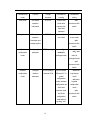
Command line provides command mode as following:
User mode
Privileged mode
Global configuration mode
Interface configuration mode
VLAN configuration mode
AAA configuration mode
RADIUS configuration mode
Domain configuration mode
The function and details of each command mode are as following:
Table 1.1. Command Line Configuration Mode
1-3
Command line
Function
mode
User mode
See switch
Prompt
Command for
Command for
character
entering
exiting
QTECH>
Connect with
exit
operation
switch after
disconnect with
information
inputting user
switch
name and
password
Privileged mode
See switch
QTECH#
operation
Input enable in
user mode
information and
exit return
to user mode
quit
manage system
disconnect with
switch
Global
Configure global
configuration
parameter
QTECH(config)#
Input configure
terminal in
mode
privileged mode
exit、end
return to
privileged mode
quit
disconnect with
switch
Interface
Configure
QTECH(config-if
Input “interface
configuration
interface
-ethernet-0/1)#
Ethernet 0/1” in
to privileged
mode
parameter
global
mode
configuration
exit return
mode, interface
to global
configuration can
configuration
enter other
mode
interface mode
quit
and VLAN
disconnect with
configuration
switch
mode without
inputting “exit”.
1-4
end return
VLAN
Configure VLAN
QTECH(config-if
Input “vlan 2” in
configuration
parameter
-vlan)#
global
mode
configuration
mode, VLAN
configuration
mode can enter
other VLAN mode
and interface
configuration
mode without
inputting “exit”.
Input “aaa” in
AAA
configuration
Create domain
QTECH(config-a
global
aa)#
configuration
mode
mode
RADIUS
Configure
configuration
RADIUS server
mode
parameter
Input “radius host
end return
QTECH(config-r
default” in global
to privileged
adius-default)#
configuration
mode
mode
exit return
to AAA
configuration
Domain
Configure
configuration
domain
mode
1.1.2
parameter
Input “domain
QTECH(config-a
test.com” in AAA
aa-test.com)#
configuration
mode
mode
quit
disconnect with
switch
Command Syntax Comprehension
This chapter describes the steps needed for command configuration. Please read this
1-5
section and related detail information of command line interface in the following sections
carefully.
The logging in identity verification of the system console of this switch is used to verify the
identity of the operating user. It permits and refuses the logging in by matching recognizing
user name and password.
Step 1: Following are showed when entering command line interface,
Username(1-32 chars):
Please input user name, press Enter button, and then the prompt is as following:
Password (1-16 chars):
Input password. If it is correct, enter the user mode with the following prompt:
QTECH>
In switch system, there are 2 different privileges. One is administrator, and the other is
common user. Common user only can see the configuration information of switch without
right to modify it but administrator can manage and configure the switch by specified
command.
1-6
Logging in as administrator can enter privileged mode from user mode.
QTECH>enable
Step 2: Input command
Skip to step 3, if the command needs input the parameter. Continue this step if the
command need input the parameter.
If the command needs a parameter, please input it. When inputting a parameter, keyword
is needed.
The parameter of the command is specified which is the number or character string or IP
address in a certain range. Input “?” when you are uncomprehending, and input the correct
keyword according to the prompt. Keyword is what is to be operated in command.
If more than one parameter are needed, please input keywords and each parameter in turn
according to the prompt until “<enter>”is showed in prompt to press enter button.
Step 3: Press enter button after inputting complete command.
For example:
!User need not input parameter
1-7
QTECH#quit
“quit” is a command without parameter. The name of the command is quit. Press enter
button after inputting it to execute this command.
!User need input parameter
QTECH(config)#vlan 3
“vlan 3”is a command with parameter and keyword, vlan of which is command keyword
and 3 of which is parameter.
1.1.3
Syntax Help
There is built-in syntax help in command line interface. If you are not sure about the syntax
of some command, obtain all command and its simple description of the current mode by
inputting “?” or help command; list all keywords beginning with the current character string
by inputting “?” closely after the command character string; input “?” after space, if “?” is in
the same location of the keyword, all keywords and its simple description will be listed, if
“?”is in the same location of parameter, all the parameter description will be listed, and you
can continue to input command according to the prompt until the prompt command is
1-8
“〈enter〉” to press enter button to execute command.
For example:
Directly input “?”in privileged mode
QTECH#?
System mode commands:
cls
clear screen
help description of the interactive help
ping ping command
quit disconnect from switch and quit
……
Input “?” closely after keyword
QTECH(config)#interf?
interface
1-9
Input “?”after command character string and space
QTECH(config)#spanning-tree ?
forward-time config switch delaytime
hello-time
max-age
priority
<enter>
config switch hellotime
config switch max agingtime
config switch priority
The command end.
4. Parameter range and form
QTECH(config)#spanning-tree forward-time ?
INTEGER<4-30> switch delaytime: <4-30>(second)
5. Command line end prompt
QTECH(config)#spanning-tree ?
<enter> The command end.
1-10
1.1.4
History command
Command line interface will save history command inputted by user automatically so that
user can invoke history command saved by command line interface and re-execute it. At
most 100 history commands can be saved by command line interface for each user. Input
“Ctrl+P” to access last command, and “Ctrl+N” for next command.
1.1.5
Symbols in command
There are all kinds of symbols in command syntax which is not a part of command but used
to describe how to input this command. Table 1-2 makes a brief description of these
symbols.
Table 1-2 Command Symbols Description
Case
Description
Vertical bars |
Vertical bars (|) means coordinate, together using with
braces ({ }) and square brackets ([ ]).
Square brackets [ ]
Square brackets ([ ]) mean optional elements.
For example:
show vlan [ vlan-id ]
Braces { }
Braces ({ }) group required choices, and vertical bars ( | )
separate the alternative elements. Braces and vertical bars
within square brackets ([{ | }]) mean a required choice within
1-11
an optional element.
For example:
muser { local | radius }
1.1.6
Command Parameter Categories
There are 5 categories command parameter as following:
scale
Two numerical value linked by hyphen in angle brackets (< >) means this
parameter is some number in the range of those two numbers.
For example: INTEGER<1-10> means user can input any integer between 1 and 10
(include 1 and 10), such as 8 is a valid number.
IP address
The prompt which is in the form of A.B.C.D. means the parameter is an IP address. A valid
IP address is needed to input.
For example: 192.168.0.100 is a valid IP address.
MAC address
The prompt which is in the form of H:H:H:H:H:H means the parameter is a MAC address. A
1-12
valid MAC address is needed to input. If a multicast MAC address is needed, there will be
related prompt.
For example: 01:02:03:04:05:06 is a valid MAC address.
Interface list
The prompt of interface list is STRING<3-4>. Interface parameter interface-num is in the
form of interface-type + interface-number. Interface-type is Ethernet and interface-number
is slot-num/port-num, in which slot-num is in the range of 0 to 2, and port-num is in the
range of 1 to 24. Seriate interfaces with the same type can be linked by to keyword, but the
port number to the right of the to keyword must be larger than the one to the left of the
keyword, and this argument only can be repeated for up to 3 times. The special declaration
of interface parameter interface list will be displayed in the command.
For example: show spanning-tree interface ethernet 0/1 ethernet 0/3 to ethernet 0/5 means
displaying spanning-tree information of interface ethernet 0/1 ethernet 0/3 to ethernet 0/5
Character string
The prompt which is in the form of STRING<3-4> means the parameter is a character
1-13
string which is in the form of 1 to 19 characters. “?”can be inputted to display the concrete
command description.
1.2
User management
There are 2 privileges for user:
administrator
normal user
Normal user can only enter user mode not privileged mode after logging in, so that he can
only see system information but not to configure it. Administrator has the right to enter all
modes, and query and configure all parameters.
1.2.1
System default user name
There is a system default built-in user name called admin, and the initial password is
123456. It is suggested modifying password when logging in switch for the first time to
avoid leaking it. This user name cannot be deleted and the privilege cannot be modified
either. It also possesses the right to manage other users. Please remember your modified
1-14
password.
1.2.2
Add user
Log in with the identity of system administrator admin to enter privileged mode, then global
configuration mode by using username command. Input user name, user’s privilege,
password to add new user according to system prompt or by using the following command.
username username [ privilege level ] { password encryption-type password }
username:User name of new users and existed users ranges from 1 to 32 printable
characters excluding such wildcards as '/'、':'、'*'、'?'、'\\'、'<'、'>'、'|'、'"' etc.
privilege:Privilege of new user ranges from 0 to 15. 0 to 1 means user while 2 to 15 means
administrator.
encryption-type: the value of it is 0 or 7. 0 means non-encryption and 7 means encryption
(It is not supported now).
password:Log in password for new user and modified password of the existed user ranges
from 1 to 16 characters or numbers.
If the privilege doesn’t configure, the default privilege is ordinary user. At most 8 users are
1-15
supported.
Caution: User name supports case insensitivity while password doesn’t support case
sensitivity.
! Add a new administrator “red”, configure privilege to be 3,and password to be 1234
QTECH(config)#username red privilege 3 password 0 1234
1.2.3
Modify password
In global configuration mode, system administrator admin can use the following command
to modify password of his or other user. Other user can only modify his own password.
username change-password
For example:
!Modify the password of user “red” to be 123456
QTECH(config)#username change-password
please input you login password : ******
please input username :red
1-16
Please input user new password :******
Please input user comfirm password :******
change user red password success.
1.2.4
Modify privilege
In global configuration mode, only administrator admin can use following command to
modify the privilege of other user.
username username [ privilege level ] { password encryption-type password }
username:User name of new users and existed users ranges from 1 to 32 printable
characters excluding such wildcards as '/'、':'、'*'、'?'、'\\'、'<'、'>'、'|'、'"' etc.
privilege:Privilege of new user or the modified privilege of existed user ranges from 0 to 15.
0 to 1 means user while 2 to 15 means administrator. Caution: the privilege of administrator
cannot be modified.
encryption-type: the value of it is 0 or 7. 0 means non-encryption and 7 means encryption
(It is not supported now).
password:Log in password for new user and modified password of the existed user ranges
1-17
from 1 to 16 characters or numbers.
If inputting nothing to modify the privilege of existed user, the privilege doesn’t modify.
Caution: User name supports case insensitivity while password doesn’t support case
sensitivity.
For example:
!Modify the privilege of administrator “red” to be 1,and password to be 1234
QTECH(config)#username red privilege 1 password 0 1234
1.2.5
Remove user name
System administrator admin can use following command to remove user name in global
configuration mode
no username username
Username is the user name to be deleted.
For example:
!Remove user red
1-18
QTECH(config)#no username red
1.2.6
View system user information
View user list, and input show username command or show usename [ username ]
command in any configuration mode to display information of all users.
For example:
!Display information of user red
QTECH(config)#show username red
display user information
user name
role
____________________________________________________________
red
1.3
ADMIN
Remote authentication of administrator
After authentication, user’s default privilege is normal user. Only when there is
Service-Type field in authentication accepting packet the value of which is Administrative,
1-19
user’s privilege is administrator.
Caution:Admin user only supports local database authentication.
1.3.1
Start RADIUS remote authentication
Use following command in globa configuration mode:
muser { local | { radius radiusname { pap | chap } [ local ] } }
It can be configured to authenticate only by RADIUS remote authentication or by local
database authentication after no response of RADIUS server caused by failing connection.
1.3.2
Display authentication configuration
Use following command to display authentication configuration.
show muser
1.4
Ways of managing switch
System provides following ways of management:
By hyper terminal accessing command-line interface(CLI)
1-20
1.4.1
By telnet managing system
By SNMP managing software management system
By Web browser,such as Internet Explorer managing system
Manage switch by hyper terminal
Use hyper terminal (or simulation terminal software) connect to Console to access system
command line interface (CLI) by hyper terminal.
Configuration: Open “file” -> “attribute” menu, popping up a window. Enter configuration to
restore it to default value, and click “setting” and then choose “auto-detect” in the pulldown
list of “terminal simulation” and click [ok]. After the successful connection and seeing
logging in interface of operation system in terminal, configure switch by command line
interface. The steps are as following:
Step 1: Connect switch Console with computer serial port;
Step 2: After the switch power on and system successful booting, logging in prompt can be
seen:
Username(1-32 chars):
1-21
Step 3: Input correct user name, press enter button, then input corresponding password. If
it is the first time to logging in switch, use default user name admin and its password
123456 to log in and operate as system administrator. If your own user name and
password exist, log in with your own user name and password;
Step 4: After successfully logging in, following information is displayed:
QTECH>
Step 5: As administrator, after entering privileged mode, use copy running-config
startup-config command to save configuration.
QTECH#copy running-config startup-config
When following information is displayed:
Startup config in flash will be updated, are you sure(y/n)? [n]y
Building, please wait...
It means system is saving configuration. Please wait, then the prompt is:
Build successfully.
1-22
It means current configuration is saved successfully.
Following information is displayed when system booting:
Ready to load startup-config, press ENTER to run or CTRL+C to cancel:
Press enter button to make saved configuration be effective, and press CTRL+C to restore
system default configuration.
Step 6: Administrator can use stop connection when overtime, while normal user can use
this function in user mode. Input timeout command to configure the overtime of user’s
logging in to be 20 minutes. And use no timeout command to configure overtime to be
non-over timing.
Step 7: Input following command after finishing operation to switch:
QTECH#quit
It is used to exit user interface.
1.4.2
Manage switch by telnet
Step 1: Establish configuration environment by connecting computer by network to switch
1-23
interface;
Step 2: Run Telnet program in computer;
Step 3: After switch is power on, input switch IP address to connect to switch, and input
configured logging in password according to the prompt, then the command line prompt is
displayed (such as QTECH>). It will be disconnected after 1 minute when there is not any
input before successfully logging in or wrong inputting of user name and password for 5
times. If there is such prompt as “Sorry,session limit reached.”, please connect later (At
most 2 telnet users are allowed to log in at the same time.);
Step 4: Use related command to configure switch system parameter or view switch
operation. If you want to enter privileged mode, user must possess the privilege of
administrator. If you need any help, please input “?”at any moment. For concrete command,
please refer to following chapters.
Step 5: If you want to exit telnet, use quit or exit command to exit in user mode, and quit
command to exit in other mode. Administrator can use stop username command in
privileged mode to exit logging in.
1-24
Chapter 2 Port Configuration
2.1
Port configuration introduction
System can provide 24 10/100Base-T Ethernet interfaces, 2 100Base-TX Ethernet
interfaces and a Console interface. Ethernet interface can work in half duplex and full
duplex mode, and can negotiate other working mode and speed rate with other network
devices to option the best working mode and speed rate automatically to predigest system
configuration and management.
2.2
2.2.1
Port Configuration
Port related configuration
Configure related feature parameter of ports should enter interface configuration mode first,
and then configure.
Interface configuration list is as following:
Enter interface configuration mode
2-1
2.2.2
Enable /disable specified interface
Configure duplex mode and speed rate
Configure interface privilege
Configure interface limited speed
Configure type of receiving frame
Configure interface type
Configure default VLAN ID of trunk port
Add access port to specified VLAN
Display interface information
Enter interface configuration mode
Enter interface configuration mode before configuration.
Configure as following in global configuration mode:
Enter interface configuration mode
interface ethernet interface-num
2-2
Interface-num is Ethernet interface number which is in the form of slot-num/port-num, in
which slot-num is in the range of 0 to 2, and port-num is in the range of 1 to 24.
2.2.3
Enable/disable specified interface
After system booting, all the interfaces are defaulted to be enable, and each interface can
be configured according to real situation.
Use following commands to enable/disable an Ethernet port.
shutdown
no shutdown
Shutdown means disable a port, while no shutdown means enable a port.
For example:
!Enable Ethernet interface 1
QTECH(config-if-ethernet-0/1)#no shutdown
!Disable Ethernet interface 25
QTECH(config-if-ethernet-1/1)#shutdown
When interface is shutdown, the physical link is working for diagnosis.
2-3
2.2.4
Configure interface duplex mode and speed rate
100 BASE TX supports the speed of 10Mbps and 100Mbps, while 100 BASE FX supports
the speed of 100Mbps. 1000 BASE TX supports the speed of 10Mbps, 100Mbps and
1000Mbps, while 1000 BASE FX supports the speed of 1000Mbps. 100 BASE TX and
1000 BASE TX support the duplex mode of half, full duplex and auto-negotiation mode.
100 BASE FX and 1000 Base FX only support the duplex mode of full duplex. By default,
100 Base FX is in the mode of 100M and full duplex, and other interfaces are
auto-negotiation. User can configure the working mode by himself. Use speed command to
configure the speed and duplex command to configure duplex.
Command form in interface mode
speed { 10 | 10auto | 100 | 100 auto | 1000 | 1000 auto | auto }
no speed
duplex { auto | full | half }
no duplex
For example:
!Configure the speed of Ethernet 0/1 to 100Mbps and duplex mode to be full duplex
2-4
QTECH(config-if-ethernet-0/1)#speed 100
QTECH(config-if-ethernet-0/1)#duplex full
2.2.5
Interface Prioruty Configuration
There are 8 priorities from 0 to 7, and the default interface priority is 0. The larger the
priority value is, the higher the priority is. And the packet with the higher priority will be
quickly handled. If there are too much packet to be handled in some interface or the packet
is urgent to be handled, priority of this interface can be configured to be high-priority.
Use following command in interface configuration mode:
Configure priority of Ethernet 0/5 to be 1
QTECH(config-if-ethernet-0/5)#priority 1
Restore the default priority of Ethernet 0/5
QTECH(config-if-ethernet-0/5)#no priority
2.2.6
Interface description configuration
Use following command to describe interface to distinguish each interface from others.
2-5
Configure it in interface configuration mode.
description description-list
For example:
!Configure description string “red” for the Ethernet 0/3
QTECH(config-if-ethernet-0/3)#description red
!Display description of Ethernet 0/3
QTECH(config)#show description interface ethernet 0/3
2.2.7
Ingress/egress bandwidth-control configuration
Egress/ingress bandwidth-control is to restrict the total speed rate of all sending and
receiving packets.
Use following command to configure engress/ingress bandwidth-control.
Configure it in interface configuration mode:
Interface engress/ingress bandwidth-control
bandwidth-control { ingress | egress } target-rate
2-6
Cancel engress/ingress bandwidth-control
no bandwidth-control { ingress | egress }
Detailed description of this command please refer to the corresponding command
reference.
2.2.8
Enable/disable VLAN filtration of receiving packet of interface
When enabling VLAN ingress filtration, received 802.1Q packet which doesn’t belong to
the VLAN where the interface locates will be dropped. The packet will not be dropped if it is
disabled.
Use this command in interface configuration mode.
ingress filtering
no ingress filtering
Example:
!Enable VLAN ingress filtration of e0/5
QTECH(config-if-ethernet-0/5)#ingress filtering
!Disable VLAN ingress filtration of e0/5
2-7
QTECH(config-if-ethernet-0/5)#no ingress filtering
2.2.9
Interface ingress acceptable-frame configuration
Configure ingress acceptable frame mode to be all types or only tagged.
Use following command in interface configuration mode to configure or cancel the
restriction to ingress acceptable-frame:
ingress acceptable-frame { all | tagged }
no ingress acceptable-frame
For example:
!Configure Ethernet 0/5 only to receive tagged frame
QTECH(config-if-ethernet-0/5)#ingress acceptable-frame tagged
2.2.10
Enable/disable interface flow-control
If the port is crowded, it needs controlling to avoid congestion and data loss. Use
flow-control command to control the flow. Use following command to enable/disable
flow-control on current Ethernet port.
flow-control
2-8
no flow-control
For example:
!Enable flow control on Ethernet 0/5
QTECH(config-if-ethernet-0/5)#flow-control
!Disable flow control on Ethernet 0/5
QTECH(config-if-ethernet-0/5)#no flow-control
Use following command in any configuration mode to display interface flow-control:
show flow-control [ interface-num ]
For example:
!Display flow-control of Ethernet 0/5
QTECH(config-if-ethernet-0/5)#show flow-control ethernet 0/5
2.2.11
Port mode configuration
Use this command to configure port mode. If a port configures to be a trunk port, the vlan
mode changes untagged into tagged, and if a port configures to be an access one, the vlan
mode changes tagged into untagged. Configure it in interface configuration mode:
2-9
Configure port mode
switchport mode { trunk | access }
Restore default port mode: access port
no switchport mode
For example:
!Configure Ethernet 0/1 to be trunk port
QTECH(config-if-ethernet-0/1)#switchport mode trunk
2.2.12
Trunk allowed VLAN configuration
Use switchport trunk allowed vlan command to add trunk port to specified VLAN.
Use no switchport trunk allowed vlan command to remove trunk port from
specified vlan.
Add trunk port to specified vlan
switchport trunk allowed vlan { vlan-list | all }
Remove trunk port from specified vlan
no switchport trunk allowed vlan { vlan-list | all }
For example:
2-10
!Add trunk ports Ethernet0/1 to VLAN 3, 4, 70 to 150
QTECH(config-if-ethernet-0/1)# switchport trunk allowed vlan 3,4, 70- 150
2.2.13
The default vlan-id of trunk port configuration
Use switchport trunk native vlan command to configure the default vlan-id (pvid) of trunk
port. When receiving untagged packet, it will be transferred to VLAN defaulted VLAN ID.
Packet receiving and sending follow IEEE 802.1Q. Configure it in interface configuration:
Configure default VLAN ID of trunk port
switchport trunk native vlan vlan-id
Restore default VLAN ID of trunk port
no switchport trunk native
Caution: above configuration is effective to trunk port. By default, default VLAN ID is 1. If
this port is not in VLAN 1, configuration fails.
2.2.14
Add access port to specified VLAN
Use switchport access command to add access port to specified VLAN, and the default
VLAN-ID is configured to be the specified VLAN. Configure it in interface configuration
2-11
mode:
Add current port to specified VLAN, and the default VLAN-ID is
configured to be the specified VLAN
switchport access vlan vlan-id
Remove current port from specified VLAN, if the default vlan-id of the
current port is the specified VLAN and this port also belongs to VLAN 1, the
default vlan-id of the current port restores to be 1, or the default VLAN ID will
not be changed.
no switchport access vlan vlan-id
The precondition to use this command is the current port is access port and the VLAN to be
added is not default VLAN 1.
2.2.15
Display interface information
Use show interface [ interface-num ] to display information of specified interface or all
interfaces:
Interface state (enable/disable)
2-12
Connection
Working mode (full duplex, half duplex or auto-negotiation)
Default VLAN ID
Interface priority
Port mode (trunk/access port)
If no parameter is input in show interface [interface-num ] command, information of all
interfaces will be displayed.
2.2.16
Display/ clear interface statistics information
Use show statistics interface [interface-num ] command in any configuration mode to
display information of specified interface or all interfaces:
Byte receiving
Unicast packet receiving
Non-unicast packet receiving
Unicast packet sending
2-13
Non-unicast packet sending
Use clear interface [interface-num | slot-num ] command in global configuration mode to
clear information of specified interface or all interfaces in specified slot or all interfaces. Use
clear interface command in interface configuration mode to clear information of current
interface.
2.3
2.3.1
Interface mirror
Brief introduction of interface mirror
System provides mirror based on interface, that is, copy packet in a or more specified
interface to monitor interface to analyze and monitor packet. For example, copy packet of
Ethernet 0/2 to specified monitor interface Ethernet 0/3 so that test and keep record by
protocols linked by monitor interface Ethernet 0/3.
System also provides packet mirror for specified source/destination MAC address. For
example, mirror packet from Ethernet 0/3 with the destination MAC address of
00:1f:ce:00:00:01.
System also provides mirror divider, that is, sample packet that can be mirrored and send it
2-14
to mirror destination interface to reduce the number of packet to mirror destination
interface.
2.3.2
Interface mirror configuration
Interface Mirror configuration command includes:
Configure mirror destination interface
Configure mirror source interface
Display interface mirror
Configure mirror interface
Configure mirror destination interface in global configuration mode:
Configure mirror interface
mirror destination-interface interface-num
This command will cancel original mirror destination interface.
Remove mirror interface
no mirror destination-interface interface-num
For example:
2-15
!Configure Ethernet 0/0/1 to be mirror interface
QTECH(config)# mirror destination-interface ethernet 0/0/1
Configure mirror source interface
Configure mirror source-interface of switch in global configuration mode:
Configure mirror source-interface
mirror source-interface { interface-list | cpu } { both | egress | ingress }
interface-list is in the form of interface-num [ to interface-num ], which can be repeated for 3
times. Cpu interface is in the form og character string “cpu”
both means mirroregress and ingress interfaces, egress means mirror interface egress and
ingress means mirror interface ingress.
Remove mirror source interface
no mirror source-interface { interface-list | cpu }
For example:
!Configure Ethernet 0/0/1 to Ethernet 0/0/12 to be mirror source interfaces
QTECH(config)# mirror source-interface ethernet 0/0/1 to ethernet 0/0/12 both
2-16
!Remove Ethernet 0/0/10 to Ethernet 0/0/12 from mirror source interfaces
QTECH(config)#no mirror source-interface ethernet 0/0/10 to ethernet 0/0/12
Display interface mirror
Use show mirror command to display system configuration of current mirror interface,
including monitor port and mirrored port list. Use this command in any configuration mode:
show mirror
For example:
!Display monitor port and mirrored port list
QTECH#show mirror
2.4
2.4.1
Port LACP convergent configuration
Brief introduction of port convergence
Port convergence is a channel group formed by many ports convergence to realize flow
load sharing for each member. When a link cannot be used, flow of this link will be
transferred to another link to guarantee the smoothness of the flow.
Basic configurations are:
2-17
1. 2 static or dynamic channel groups can be configured and at most 12 interface
members can be configured in each group, and at most 8 interfaces can be
convergent at the same time in each group which is determined by up/down status,
interface number, LACP priority. Each group is defined to be a channel group, and
the command line is configured around it.
2. Load balance strategy of each group can be divided into source MAC,
destination MAC, source and destination MAC, source IP, destination IP, and
source and destination IP. The default strategy is source MAC.
3. System and interface LACP priority can be configured. The default system
priority is 32768,and interface priority is 128. To remove system and interface
priority is to restore them to default ones.
4. LACP protocol of each interface can be configured. In static mode, interface is
static convergent, and LACP protocol does not run; in active mode, interface will
initiate LACP negotiation actively; in passive mode, interface only can response
LACP negotiation. When interconnecting with other device, static mode only can
interconnect with static mode; active can interconnect with active and passive
mode, but passive mode only can interconnect with active mode. The default
mode of interface is ACTIVE mode.
Each convergent interface need same layer 2 features, so there are following restrictions
to interfaces in a channel group:
1.
Static convergent interfaces and dynamic convergent interfaces can not be in a same channel group, but
there can be static convergent channel as well as dynamic convergent channel.
2.
Each interface in a same channel group must possess the same features as following: interface speed
rate, working mode of full duplex, STP/GVRP/GMRP function, STP cost, STP interface priority, VLAN
2-18
features (interface mode, PVID, VLAN belonged to, tag vlan list of access interface, allowed vlan list of
trunk interface) and layer 2 multicast group belonged to.
3.
If modifying the feature of one interface in the channel group, other interfaces will be modified
automatically in the same place. The feature refers to point 2.
4.
After convergence, static hardware item (ARL, MARL, PTABLE, VTABLE) will be modified, but there will
be delay.
5.
After convergence, only host interface can send CPU packet. If STP changes status of some interface,
the status of the whole channel group will be changed.
6.
After convergence, when transferring layer 2 protocol packet, STP/GARP will not transfer packet to the
current channel grou. If transferring to other channel group, only one packet will be transferred.
If there are members in the channel group, this channel group cannot be deleted. Delete
interface members first.
Influence on choosing link redundancy caused by LACP system and interface priority.
LACP provides link redundancy mechanism which needs to guarantee the redundancy
consistency of two interconnected switches and user can configure redundancy link
which is realized by system and interface priority. The redundancy choosing follows the
following steps:
First, determine which switch is the choosing standard. For LACP packets interaction,
each of the two switches knows each other’s LACP system priority and system MAC and
compares the LACP system priority to choose the smaller one; if the system priority is
the same, compare MAC and choose the smaller one.
1、 Then, choose redundancy link according to the interface parameter of the chosen
switch. Compare interface LACP priority, and choose the inferior one to be
2-19
redundant. If the priorities are the same, choose the interface whose interface
number is larger to be redundant.
2.4.2
Interface convergent configuration
Port LACP configuration command includes:
Channel group configuration
Please configure it in global configuration mode:
channel-group channel-group-number
Parameter “channel-group-number” is range from 0 to 5.
For example:
!Create a channel group with the group number being 0
QTECH(config)#channel-group 0
Delete channel group
no channel-group channel-group-number
Add add port members to the group
channel-group channel-group-number mode {active | passive | on}
In interface configuration mode, add current interface to channel group and specify the
2-20
mode of interface. If the channel group doesn’t exist, create it.
For example:
!Add Ethernet 0/3 to channel-group 3 and specify the port to be active mode
QTECH(config-if-ethernet-0/0/3)#channel-group 3 mode active
Delete interface member in channel group
no channel-group channel-group-number
In interface configuration mode, delete current interface from channel group.
For example:
!Delete interface Ethernet 0/0/3 from channel group 3
QTECH(config-if-ethernet-0/0/3)#no channel-group 3
Configure load balance of switch
channel-group load-balance
{dst-ip|dst-mac|src-dst-ip|src-dst-mac|src-ip|src-mac}
choose physical link program when packet sending.
For example:
2-21
!Specify load-balance of channel-group 0 is destination mac
QTECH(config)#channel-group load-balance dst-mac
Configure system LACP priority
lacp system-priority priority
For example:
!Configure LACP system priority is 40000
QTECH(config)#lacp system-priority 40000
Delete system LACP priority
no lacp system-priority
Use this command to restore system default LACP priority to be 32768.
Configure interface LACP priority
lacp port-priority priority
Use this command in interface configuration mode to configure LACP priority of the current
interface
For example:
!Configure lacp port-priority of Ethernet 0/2 to be 12345
2-22
QTECH(config-if-ethernet-0/0/2)#lacp port-priority 12345
Delete interface LACP priority
no lacp port-priority
Use this command to restore interface default LACP priority to be 128.
Display system LACP ID
show lacp sys-id
System id is in the form of 16 characters of system priority and 32 characters of system
MAC address.
For example:
!Display lacp system id
QTECH(config)#show lacp sys-id
Display local information of channel group
show lacp internal [channel-group-number]
Use show lacp interval command to display the information of group members, if the there
is no keywords, all groups are displayed.
For example: Display the member information of channel group 2.
2-23
QTECH#show lacp internal 2
Display information of neighbour interface of channel group
show lacp neighbor [channel-group-number]
Use show lacp neighbor command to display the information of the neighbour port in the
group. If there is no keyword, the neighbor ports of all the groups are displayed.
For example: Display the information of the neighbour port of the group 2
QTECH#show lacp neighbor 2
2.5
2.5.1
Interface CAR configuration
Brief introduction of interface CAR
Interface CAR is used to restrict the speed rate impacted CPU of single interface. CPU
can make speed rate statistics of each interface. If the speed rate is larger than the
configured threshold (it is defaulted to be 300 packet/second), disable this interface and
send trap of interface being abnormal. After a certain time (it is defaulted to be 480
seconds), re-enable the interface. If this interface will not be re-disabled by interface
CAR in 2 seconds, the storm of impacting CPU by interface is over, and the interface
recovers, and sends the trap of interface being normal. Caution: If the re-enabled
interface is disable again by impacting CPU packet in 2 seconds, no trap of interface
being abnormal is sent.
2-24
2.5.2
Port CAR configuration command list
Port CAR configuration command includes:
2.5.3
Enable/disable interface CAR globally
Enable/disable interface CAR on a port
Configure interface CAR re-enable time
Configure interface CAR
Display interface CAR status
Enable/disable interface globally
Configure it in global configuration mode
Enable global interface
port-car
Disable global interface
no port-car
By default, port-car globally enables
2-25
For example:
!Enable port-car globally
QTECH(config)#port-car
2.5.4
Enable/disable interface CAR on a port
Please configure it in interface configuration mode:
Enable interface CAR
port-car
Disable interface CAR
no port-car
For example:
!Enable port-car of Ethernet 0/8
QTECH(config-if-ethernet-0/8)#port-car
2.5.5
Configure the reopen time of the port shutdown by port-car
2-26
Please configure it in global configuration mode:
Configure the reopen time of the port shutdown by port-car
port-car-open-time port-car-open-time
By default, port-car-open-time is 480 seconds
For example:
!Configure port-car-open-time to be 10 seconds
QTECH(config)#port-car-open-time 10
2.5.6
Configure the port-car-rate
Please configure it in global configuration mode:
Configure the port-car-rate
port-car-rate port-car-rate
Default port-car-rate is 300 packet/second
For example:
!Configure port-car-rate to be 200 packet/second
2-27
QTECH(config)#port-car-rate 200
2.5.7
Display port-car information
Input following command in any configuration mode to display port-car
information:
show port-car
For example:
!Display port-car information
QTECH(config)#show port-car
2.6
2.6.1
Port Alarm Configuration
Brief introduction of port alarm configuration
System can monitor port packet receiving rate. If the rate of receiving packet is beyond
the interface flow exceed threshold, send alarm of large interface flow and the interface
is in the status of large interface flow. In this status, if the rate of receiving packet is lower
than the interface flow normal threshold, send alarm of normal interface flow. This
function can actively report the rate of receiving packet to user.
2-28
2.6.2
Port alarm configuration list
Port alarm configuration command includes:
2.6.3
Enable/disable port alarm globally
Enable/disable port alarm on the port
Configure the exceed threshold and normal threshold of port alarm
Display port alarm
Enable/disable port alarm globally
Please configure it in global configuration mode:
Enable port alarm globally
alarm all-packets
Disable port alarm globally
no alarm all-packets
By default, alarm all-packets enable.
For example:
2-29
! Enable global alarm all-packets
QTECH(config)#alarm all-packets
2.6.4
Enable/disable port alarm on the port
Please configure it in interface configuration mode:
Enable port alarm on the port
alarm all-packets
Disable port alarm on the port
no alarm all-packets
For example:
!Enable alarm all-packets of Ethernet 0/0/8
QTECH(config-if-ethernet-0/0/8)# alarm all-packets
2.6.5
Configure the exceed threshold and normal threshold of port alarm
Please configure it in global configuration mode:
2-30
Configure the exceed threshold and normal threshold of port alarm
alarm all-packets threshold [ exeed exceed ] [ normal normal ]
Caution: Exceed > normal. By default, 100 BASE exceed threshold is 85,normal threshold
is 60
For example:
!Configure alarm all-packets exceed threshold to be 500,and normal threshold to be 300
QTECH(config)#alarm all-packets threshold exceed 500 normal 300
2.6.6
Display port alarm
Input following command in any configuration mode to display global
interface alarm:
show alarm all-packets
For example:
!Display global alarm all-packets information
QTECH(config)#show alarm all-packets interface ethernet 0/0/1
2-31
Input following command in any configuration mode to display interface
alarm on the port:
show alarm all-packets interface [ interface-list ]
Keyword “interface-list” is alternative. If there is no keyword, the alarm all-packets of all the
interfaces are displayed, or the information of specified port is displayed.
For example:
!Display the alarm all-packets interface information of Ethernet 0/0/1
QTECH(config)#show alarm all-packets interface ethernet 0/0/1
2.7
2.7.1
Interface shutdown-control Configuration
Brief introduction of shutdown-control
Interface shutdown-control is used to restrict the speed rate of unicast\
multicast\broadcast of single interface. If the rate is beyond the configured
restricted value(that can be configured), the interface will be shut down and
failure trap will be sent. After a while(it is defaulted to be 480 seconds, which
can be configured), it may reopen. If the interface will not reshutdown-control
in 2 seconds, it turns normal and normal trap will be sent. If the interface
reshutdown-control in 2 seconds, the failure trap will not be sent.
2-32
2.7.2
Interface shutdown-control Configuration list
Interface shutdown-control Configuration list is as following:
2.7.3
shutdown-control Configuration
Configure shutdown-control open-time
Display shutdown-control
shutdown-control Configuration
Configure it in interface configuration mode:
Enable shutdown-control
shutdown-control [ broadcast | multicast | unicast ] target-rate
Disable shutdown-control
no shutdown-control [ broadcast | multicast | unicast ]
By default, shutdown-control is disabled.
Example:
!Enable shutdown-control of e0/8 for broadcast and speed rate is 100pps.
2-33
QTECH(config-if-ethernet-0/8)#shutdown-control broadcast 100
2.7.4
Configure shutdown-control open-time
Configure it in global configuration mode:
Configure shutdown-control open-time
shutdown-control-open-time
The default shutdown-control open-time is 480 seconds.
Example:
!Configure shutdown-control-open-time of CAR is 20 seconds
QTECH(config)# shutdown-control-open-time 20
2.7.5
Display shutdown-control
Configure it in any configuration mode:
show shutdown-control
Example:
2-34
!Display interface shutdown-control information
QTECH(config)#show shutdown-control
2-35
Chapter 3 VLAN Configuration
3.1
Brief introduction of VLAN
VLAN (Virtual Local Area Network )is a technology divided devices in LAN logically not
physically into network interfaces to realize virtual workgroup. IEEE promulgated IEEE
802.1Q protocol standard draft to realize standardized VLAN.
VLAN technology allows network administrator to divide a physical LAN into different
broadcast domain or VLAN logically. Each VLAN contain a group of computer station with
the same need to possess the same attribute with the LAN formed physically. But it is
divided logically not physically, so each working station of the same VLAN need not be in
the same physical space. Broadcast and unicast flow in a VLAN will not transfer to other
VLAN, which is helpful to control the flow, reduce device cost, predigest network
management and improve network security. Following are VLAN features:
Flow control helped by VLAN
In traditional network, large number of broadcast data is sent to all network devices to
3-1
cause network congestion. VLAN can configure the intercommunicated devices in each
VLAN to reduce broadcast to improve network efficiency.
provides higher security
Device in one VLAN can only intercommunicate with the device in the same VLAN. For
example, devices in R&D department can intercommunicate with production department
only by the routing device, which greatly improved system security for the two departments
cannot intercommunicate directly.
3.2
VLAN interface type
System supports IEEE 802.1Q which possesses two types of VLAN interfaces. One is
tagged, and the other is untagged.
Tagged interface can ad VLAN ID, priority and other VLAN information to the head of the
packet which is out of the interface. If the packet has included IEEE 802.1Q information
when entering the switch, the mark information will not be changed; if the packet has not
includes IEEE 802.1Q mark information, system will determine the VLAN it belongs to
according to the default VLAN ID of the receiving interface. Network devices supported
3-2
IEEE 802.1Q will determine whether or not to transmit this packet by the VLAN information
in the mark.
Untagged interface can drop the mark information from all the packets which are out of the
interface. When a frame is out of a untagged interface, it will not contain IEEE 802.1Q mark
information. The function of dropping the mark makes the packet can be transferred from
the network device supported mark to the one which doesn’t support it.
Now, only the switch supported IEEE 802.1Q can be recognize IEEE 802.1Q frame so only
a port linking to a switch supported IEEE 802.1Q can be configured to be Tagged port.
3.3
Default VLAN
There is a default VLAN of production, which possesses following features:
The name of this VLAN is Default which can be modified.
It includes all ports which can be added and deleted.
All the port mode of default VLAN is untagged which can be modified to
be tagged.
VLAN ID of default VLAN is 1 which cannot be deleted.
3-3
3.4
3.4.1
VLAN configuration
VLAN configuration list
Configure VLAN should create VLAN according to the need first, then configure VLAN
interface and its parameter.
VLAN configuration list is as following:
3.4.2
Create/delete VLAN
Add/delete VLAN interface
Specify/delete VLAN description
Configure interface type
Configure interface default vlan ID
Configure tag vlan
Display VLAN information
Create/delete VLAN
Configure it in global configuration mode:
3-4
Enter VLAN configuration mode or create VLAN and enter it
vlan vlan-list
Delete created VLAN or specified VLAN except VLAN 1
no vlan { vlan-list | all }
VLAN-ID allowed to configure by system is in the range of 1 to 4094. vlan-list can be in the
form of discrete number, a sequence number, or the combination of discrete and sequence
number, discrete number of which is separate by comma, and sequence number of which
is separate by subtraction sign, such as: 2,5,8,10-20. Use the vlan command to enter
VLAN configuration mode. If the vlan identified by the vlan-id keyword exists, enter VLAN
configuration mode. If not, this command creates the VLAN and then enters VLAN
configuration mode. For example, if VLAN 2 is not existed, system will create VLAN 2 first,
then enter VLAN configuration mode; if VLAN 2 has existed, enter VLAN configuration
mode.
When deleting VLAN, if the vlan-list is specified, delete corresponding VLAN. If choosing all,
delete all existed VLAN except default VLAN. If deleting interface in VLAN, and default
VLAN id is the same as the VLAN to be deleted, restore interface default VLAN ID to be
3-5
default VLAN ID.
If the VLAN to be removed exists in the multicast group, remove the related multicast group
first.
3.4.3
Add/delete VLAN interface
Use the switchport command to add a port or multiple ports to current VLAN. Use the no
switchport command to remove a port or multiple ports from current VLAN. Use following
commands in VLAN configuration mode:
Add interface to specified VLAN
switchport { interface-list | all }
Delete some interface from specified VLAN
no switchport { interface-list | all }
Interface-list is the optioned interface list which means a or more interfaces. If choose all,
add all ports to current VLAN; if choosing all when deleting interface, all ports in current
VLAN will be deleted. When deleting interface from VLAN 1, if the PVID of interface is 1,
modify the PVID to be other VLAN ID before deleting this interface. When deleting interface
3-6
in other VLAN ID, port PVID should be the same as the VLAN ID, and the port is also in
VLAN 1, delete it. If this port is not in VLAN 1, modify port PVID to be other VLAN ID, delete
the port.
There are two status of the interface in VLAN, one is tagged and the other is untagged. If
the port is access port, add it to VLAN with the status of being untagged. If it is trunk port,
change it to be tagged in VLAN.
For example:
!Add Ethernet 1, 3, 4, 5, 8 to current VLAN
QTECH(config-if-vlan)#switchport ethernet 0/0/1 ethernet 0/0/3 to ethernet 0/0/5 ethernet
0/0/8
!Remove Ethernet 3, 4, 5, 8 from current VLAN
QTECH(config-if-vlan)#no switchport ethernet 0/0/3 to ethernet 0/0/5 ethernet 0/0/8
Command switchport access vlan and its no command can also add and delete port to or
from VLAN. Please refer to interface configuration of chapter 2.
3.4.4
Specify/restore VLAN description
3-7
The description string is used to distinguish each VLAN. Please configure it in VLAN
configuration mode:
Specify a description string to specified VLAN
description string
Delete description string of specified VLAN
no description
string:It is in the range of 1 to 32 characters to describe the current VLAN. The characters
can be printable, excluding such wildcards as '/'、':'、'*'、'?'、'\\'、'<'、'>'、'|'、'"'etc.
For example:
!Specify the description string of the current VLAN as “market”
QTECH (config-if-vlan)#description market
!Delete the description string of VLAN
QTECH(config-if-vlan)#no description
3.4.5
Configure interface type
Use switchport mode command to configure port type. Please refer to interface
3-8
configuration in chapter 2.
3.4.6
Configure interface default vlan ID
System supports IEEE 802.1Q. When receiving a untagged packet, system will add a tag
to the packet, in which the VLAN ID is determined by the default VLAN ID of the receiving
port. The command to configure default VLAN of trunk port is switchport trunk native vlan;
for acess port, use switchport access vlan command to configure default VLAN of specified
interface. The detailed introduction of the corresponding no command is in chapter 2.
For example:
!Configure default vlan-id of Ethernet interface 1 to be 2
QTECH(config-if-ethernet-0/1)#switchport mode access
QTECH(config-if-ethernet-0/1)#switchport access vlan 2
Caution: To use switchport trunk native vlan vlan-id must guarantee the
specified interface to be trunk, and belongs to specified VLAN, and the VLAN ID
is not 1. Use switchport access vlan vlan-id to configure interface default VLAN
and add it to the VLAN. The specified interface is access, and the VLAN is
3-9
existed and is not the default VLAN.
3.4.7
Configure tag vlan
When the port is access without tag vlan configuration, it can only send untagged packet. If
it wants to send tagged packet, use tag vlan vlan-list command. Use its no command to
disable this function. The interface must be access, and configure it in interface
configuration mode.
For example:
!Configure Ethernet interface 1 to send IEEE 802.1Q packet with tag VLAN 5, VLAN 7-10
QTECH(config-if-ethernet-0/0/1)#tag vlan 5,7-10
3.4.8
Display VLAN information
VLAN information is VLAN description string, vlan-id, VLAN status and interface members
in it, tagged interfaces, untagged interfaces and dynamic tagged interfaces. Interface
members consist of tagged and untagged members.
show vlan [ vlan-id ]
If the VLAN with specified keyword exists, this command displays the information of the
3-10
specified VLAN. If no keyword is specified, this command displays the list of all the existing
VLANs
For example:
!Display the information of existed VLAN 2.
QTECH(config)#show vlan 2
3.5
PVLAN
PVLAN means private VLAN which is used to realize interface isolation function. These
private VLANs are unknown to uplink devices to save the resource of public VLAN.
Nowadays, factories in this field use SVL to realize PVLAN and provide corresponding
configuration command. But there is some shortage by using SVL, such as: the uplink and
downlink interfaces are access, and MAC address wasting. Our company uses redirection
technology to realize PVLAN and overcome the shortage of SVL, any interface can be
access or trunk, which entirely realize PVLAN. The detailed information of PVLAN
configuration can refer to interface isolation configuration.
3.6
GVRP configuration
3-11
3.6.1
Brief introduction of GVRP
GVRP, GARP VLAN Registration Protocol is a kind of application of GARP. It is based on
GARP working mechanism to maintain VLAN dynamic register information in switch and
transfer it to other switch. All switch that support GVRP can receive VLAN register
information from other switches and dynamically upgrade local VLAN register information
which includes: current VLAN members, and by which interface can reach VLAN members.
And all switches supported GVRP can transfer local VLAN register information to other
switches to make the consistency of the VLAN information of devices which support GVRP.
VLAN register information transferred by GVRP includes local munal configuration of static
register information and the dynamic register information of other switch.
3.6.2
GVRP Configuration list
In all configurations, enable global GVRP first before enable GVRP on a port. GVRP must
be enabled in the two ends of trunk link which follows IEEE 802.1Q standard.
GVRP Configuration list is as following:
GVRP Configuration list is as following:
3-12
3.6.3
Enable/disable global GVRP
Enable/disable GVRP on a port
Display GVRP
Add/delete vlan that can be dynamic learnt by GVRP
Display vlan that can be learnt by GVRP
Enable/disable global GVRP
Please configure it in global configuration mode:
Enable global GVRP
gvrp
Disable global GVRP
no gvrp
By default, GVRP globally disables
For example:
!Enable GVRP globally
3-13
QTECH(config)#gvrp
3.6.4
Enable/disable GVRP on a port
Please configure it in interface configuration mode:
Enable GVRP on a port
gvrp
Disable GVRP on a port
no gvrp
For example:
!Enable GVRP on Ethernet port 8
QTECH(config-if-ethernet-0/8)#gvrp
Caution: Enable global GVRP before enable GVRP on a port. By default, global
GVRP deisables and GVRP on a port can be enabled in trunk mode interface.
3.6.5
Display GVRP
Use following command in any configuration mode to display global
3-14
GVRP:
show gvrp
Use following command in any configuration mode to display GVRP on
a port:
show gvrp interface [ interface-list ]
Interface-list keyword is optional. If this keyword unspecified, the command displays GVRP
information for all the Ethernet ports. If specified, the command displays GVRP information
on specified Ethernet port.
For example:
!Display GVRP information on interface Ethernet 0/1
QTECH(config)#show gvrp interface ethernet 0/1
3.6.6
Add/delete vlan that can be dynamic learnt by GVRP
Use garp permit vlan command to add configured static vlan to GVRP module for other
switches to learn. Configure it in global configuration mode:
3-15
garp permit vlan vlan-list
no garp permit vlan [ vlan-list ]
For example: !Add vlan 2, 3, 4 to GVRP
QTECH(config)#garp permit vlan 2-4
3.6.7
Display vlan that can be learnt by GVRP
Use show garp permit vlan command to display current static vlan permitted learning by
GVRP
show garp permit vlan
For example:
Display current static vlan permitted learning by GVRP
QTECH(config)#show garp permit vlan
3.6.8
Examples for GVRP configuration
!Enable GVRP on Ethernet port 2
QTECH(config-if-ethernet-0/0/2)#gvrp
!Disable GVRP on Ethernet port 2
3-16
QTECH(config-if-ethernet-0/0/2)#no gvrp
3.7 QinQ configuration
3.7.1
Brief introduction of QinQ
QinQ is used for the commnunication between discrete client vlan whose service model is
the interconnection of one or more switches supported QinQ by service provider interfaces
which are in service provider vlan. The interface linking client vlan is called customer
interface. Packet with client vlan tag will add a tag head with the vlan id being service
provider vlan when passing through the customer interface. The tag head will be stripped
when passing through service provider vlan.
3.7.2
QinQ configuration list
Configure global QinQ
Configure QinQ mode of interface
Configure dynamic QinQ of interface
Enable/disable vlan-swap
3-17
Configure vlan-swap of interface
Display dynamic QinQ
Display vlan-swap
3.7.3
Configure global QinQ
QTECH QSW-2700 supports following two QinQ style:
1、static 802.1q in 802.1q. In this mode, vlan protocol number of configured port can be
configured but cannot be configured whether to ignore tag head of ingress packet,if the
vlan protocol number is not equal to the configured port number or the port is configured to
ignore ingress tag head, a new tag head will be added to the 12th to 13th bit;
2、flexible 802.1q in 802.1q. Configure port vlan protocol number not the ignorance
attribution of the ingress port. Only when vlan protocol number of ingress packet is not the
same as the port configuration value and not the default value 8100, a new tag head will be
added. If egress is TAG,TPID of TAG head is configured TPID.
3、use dtag outer-tpid tpid to change TPID of out tag. If there is untag packet through this
switch and just out with one tag, TPID also will be charged to be what you configure
3-18
before.The default is 0X8100.
!Use dtag command to enable/disable QinQ globally in global configuration mode.
dtag
dtag flexible-qinq
dtag outer-tpid tpid
no dtag
For example:
!Configure global QinQ TPID to be 9100
QTECH (config) dtag outer-tpid 9100
3.7.4
Configure QinQ mode of interface
There are two kinds of interface modes: one is service provider port, the other is customer
port. The customer port do not permit ignoring tag head of ingress packet and the service
port permits.
!It is in the interface configuration mode.
dtag mode { customer | uplink }
Example:
3-19
Configure interface to be customer
QTECH (config-if-ethernet-0/1)#dtag mode customer
3.7.5
Configure dynamic QinQ of interface
1.Configure a series vlan to be dynamic QinQ with the start vlan and destination vlan. In
the precondition of all vlan tag packets between start vlan are not transparent transmitted,
they will transmit in the form of double tag head with destination vlan.
!The command mode is global configuration mode
dtag insert [start vlan of the consecultive vlan ] [end vlan of the consecultive vlan ]
[ destination vlan ]
Example:
Configure all vlan tag packets to add a tag head with destination vlan3 from the start vlan1
to end vlan2.
QTECH (config-if-ethernet-0/1)#dtag insert vlan1 vlan2 vlan3
2.Delete a consecultive vlan in configured dynamic QinQ on the form of start vlan and
3-20
destination vlan, in which the parameter imputed start vlan and the destination vlan must
be the same as configuring a vlan series.
!The command mode is global configuration mode
no dtag insert [ start vlan of consecultive vlan ] [end vlan of the consecultive vlan ]
[ destination vlan ]
Example:
Delete all configured vlan tag packets to add a tag head with destination vlan3 from the
start vlan1 to end vlan2.
QTECH (config-if-ethernet-0/1)#no dtag insert vlan1 vlan2 vlan3
3.Configure a series vlan to be transparent transmitted in dynamic QinQ in the form of start
vlan. All vlan tag packets can be transmitted from start vlan without adding new tag head
because the priority of transparent transmission id superior than adding tag head,
transparent transmission will not be influenced by dtag inset command.
!Command mode is global configuration mode
dtag pass-through [start vlan of consecultive vlan] [end vlan of the consecultive vlan ]
3-21
Example:
Configure all vlan tag packet to be transparent transmission from start vlan1 to end vlan2
QTECH (config-if-ethernet-0/1)# dtag pass-through vlan1 vlan2
4.Delete all configured all vlan tag packet to be transparent transmission in the form of start
vlan, in which the parameter imputed start vlan must be the same as configuring a vlan
series.
!Command mode is global configuration mode
no dtag pass-through [start vlan of consecultive vlan ] [end vlan of the consecultive vlan ]
Example:
Delete all configured all vlan tag packet to be transparent transmission from start vlan1 to
end vlan2
QTECH (config-if-ethernet-0/1)#no dtag pass-through vlan1 vlan2
3.7.6
Enable/disable vlan-swap
Configure it in global configuration mode:
3-22
Enable vlan-swap
vlan-swap
Disable vlan-swap
no vlan-swap
By default, vlan-swap is disabled.
Example:
!Enable vlan-swap
QTECH (config)#vlan-swap
3.7.7
Configure vlan-swap of interface
1.Configure vlan in the tag to be repaced by configured vlan
!Command mode is interface configuration mode
vlan-swap [ original vlanID ] [ swap vlan ID ]
Example:
Configure vlan1 in tag head to be replaced by vlan2
3-23
QTECH (config -if-ethernet-0/1)#vlan-swap vlan1 vlan2
2.Delete configured vlan swap parameter
!Command mode is global configuration mode
no vlan-swap [original vlanID ] [ swap vlan ID ]
Example:
Delete configured vlan1 in tag to be repaced by vlan2
QTECH (config -if-ethernet-0/1)#no vlan-swap vlan1 vlan2
3.7.8
Display dynamic QinQ
1.Display dynamic vlan
!Command mode is global configuration mode
show dtag insert
Example:
Display dynamic vlan
QTECH (config)#show dtag insert
3-24
2. Display transparent transmission vlan
!Command mode is global configuration mode
show dtag pass-through
Example:
Display transparent transmission vlan
QTECH (config)#show dtag pass-through
3.7.9
Display vlan-swap
Display vlan swap status
!Command mode is global configuration mode
show vlan-swap
Example:
Display vlan swap status
QTECH (config)#show vlan-swap
3-25
Chapter 4 Multicast Protocol Configuration
4.1
Brief introduction of GMRP
GMRP(GARP Multicast Registration Protocol) is a kind of application of GARP(Generic
Attribute Registration Protocol), which is based on GARP working mechanism to maintain
the dynamic multicast register information in switch. All switches supported GMRP can
receive multicast register information from other switches and upgrade local multicast
register information dynamically and transfer it to other switches to make the consistency of
multicast information of devices supported GMRP in the same switching network. Multicast
register information transferred by GMRP includes local manual configuration of static
multicast register information and the dynamic multicast register information of other
switch.
4.2
4.2.1
GMRP Configuration
GMRP Configuration list
In all configurations, enable global GMRP first before enable GMRP on a port. GMRP
4-1
Configuration list is as following::
4.2.2
Enable/disable global GMRP
Enable/disable GMRP on a port
Display GMRP
Add/delete multicast that can be dynamic learnt by GMRP
Display multicast that can be learnt by GMRP
Enable/disable global GMRP
Please configure it in global configuration mode:
Enable global GMRP
gmrp
Disable global GMRP
no gmrp
By default, GMRP globally disables
For example:
4-2
!Enable GMRP globally
QTECH(config)#gmrp
4.2.3
Enable/disable GMRP on a port
Enable global GMRP before enable GMRP on a port. Please configure it in interface
configuration mode:
Enable GMRP on a port
gmrp
Disable GMRP on a port
no gmrp
For example:
!Enable GMRP on Ethernet port 3
QTECH(config-if-ethernet-0/3)#gmrp
Caution: Enable global GMRP before enable GMRP on a port. By default, global
GMRP deisables and GMRP on a port can be enabled in trunk mode interface.
4-3
4.2.4
Display GMRP
Use following command in any configuration mode to display global
GMRP:
show gmrp
Use following command in any configuration mode to display GMRP on
a port:
show gmrp interface [ interface-list ]
Interface-list keyword is optional. If this keyword unspecified, the command displays GMRP
information for all the Ethernet ports. If specified, the command displays GMRP information
on specified Ethernet port.
For example:
!Display GMRP information of Ethernet 0/2 to ethernet 0/4 ethernet 2/1
QTECH(config)#show gmrp interface ethernet 0/2 to ethernet 0/4 ethernet 2/1
port GMRP status
4-4
e0/2 enable
e0/3 enable
e0/4 enable
e2/1 enable
Total entries: 4.
4.2.5
Add/delete multicast that can be dynamic learnt by GMRP
Add configured static multicast group to GMRP for other switch learning it.
garp permit multicast [ mac-address mac vlan vlan-id ]
Example:
Add multicast group 01:00:5e:00:01:01 vlan 1 to GMRP
QTECH(config)#garp permit multicast mac-address 01:00:5e:00:01:01 vlan 1
4.2.6
Display multicast that can be learnt by GMRP
Display multicast group can be statically learnt by GMRP.
show garp permit multicast
For example: Display multicast group that can be statically learnt by GMRP
4-5
QTECH(config)#show garp permit multicast
4.3
4.3.1
IGMP Snooping Configuration
Brief introduction of IGMP Snooping
IGMP(Internet Group Manangement Protocol)is a part of IP protocol which is used to
support and manage the IP multicast between host and multicast router. IP multicast
allows transferring IP data to a host collection formed by multicast group. The relationship
of multicast group member is dynamic and host can dynamically add or exit this group to
reduce network load to the minimum to realize the effective data transmission in network.
IGMP Snooping is used to monitor monitor IGMP packet between host and routers. It can
dynamically create, maintain and delete multicast address table according to the adding
and leaving of the group members. At that time, multicast frame can transfer packet
according to his own multicast address table.
4.3.2
IGMP Snooping configuration
Use following command to control IGMP Snooping to establish the MAC address multicast
4-6
transmission table in layer 2.
Use following command in global configuration mode:
Enable IGMP Snooping
igmp-snooping
Disable IGMP Snooping
no igmp-snooping
By default,IGMP Snooping disables.
Display IGMP Snooping
Use following command in any mode to see IGMP Snooping:
For example:
!Display IGMP snooping information
QTECH(config)#show igmp-snooping
4.3.3
IGMP Snooping multicast interface aging time configuration
Use following command in global configuration mode to configure host-aging-time dynamic
multicast group learnt by igmp-snooping:
4-7
igmp-snooping host-aging-time
Use following command to display host-aging-time dynamic multicast group learnt by
igmp-snooping:
show igmp-snooping
For example:
!Configure host-aging-time of the dynamic multicast group learnt by igmp-snooping to be
10 seconds
QTECH(config)#igmp-snooping host-aging-time 10
4.3.4
IGMP Snooping max-response-time configuration
Configure the max response time to delete group interface when receiving a leave packet:
igmp-snooping max-response-time seconds
Use this command in global configuration mode.
For example:
!Configure the max-response-time of igmp-snooping is 13 seconds
4-8
QTECH(config)#igmp-snooping max-response-time 13
4.3.5
IGMP Snooping interface fast-leave configuration
Configure interface fast-leave when fast-leave enables, if the fast-leave packet is received,
the interface leaves the aging group, or the time to leave is determined by the
max-response-time:
igmp-snooping fast-leave
Use this command in interface configuration mode.
For example:
!Enable igmp-snooping fast-leave
QTECH(config-if-ethernet-0/1)#igmp-snooping fast-leave
4.3.6
Configure the number of the multicast group allowed learning
Use igmp-snooping group-limit command to configure the number of the multicast group
allowed learning.
igmp-snooping group-limit limit
4-9
Use this command in global configuration mode.
For example:
!Configure the igmp-snooping group-limit to be 10
QTECH(config-if-ethernet-0/1)#igmp-snooping group-limit 10
4.3.7
IGMP Snooping permit/deny group configuration
Configure igmp-snooping permit/deny group and default group learning regulation.
Configure igmp-snooping permit/deny group in interface configuration mode:
igmp-snooping permit/deny group group-address
Configure igmp-snooping default group learning regulation in global configuration mode:
igmp-snooping deny/permit group all
For example:
!Configure Ethernet 0/1 not to learn multicast 01:00:5e:00:01:01
QTECH(config-if-ethernet-0/1)#igmp-snooping deny group 01:00:5e:00:01:01
!Configure the learning regulation of default group to allow all multicast group
4-10
QTECH(config)#igmp-snooping permit group all
4.3.8
IGMP Snooping route-port forward configuration
Multicast routers interface is the interface received IGMP inquiring packet (It is also called
mix router interface.).
Use igmp-snooping route-port forward command to configure whether to add router
interface to IGMP snooping learning group. By default, router interface to IGMP snooping
learning group is not added.
Use following command in global configuration mode:
igmp-snooping route-port forward
no igmp-snooping route-port forward
For example:
!Enable igmp-snooping route-port forward
QTECH(config)#igmp-snooping route-port forward
4.4
Static Multicast Configuration
4-11
4.4.1
Brief introduction of Static Multicast
Static multicast configuration command is used to crewate multicast group and add
interfaces to it. If the switch supports multicast, when receiving multicast packet, detect
whether there is multicast group. If it doesn’t exist, transfer the multicast packet as
broadcast packet. If it exists, transfer the multicast packet to all interface members of this
multicast group.
4.4.2
Static Multicast Configuration
Static Multicast Configuration list
Configure static multicast in following turns:
Create multicast group
Add interfaces to multicast group
Display multicast group information
Delete interface members from multicast group
Delete multicast group
4-12
Create multicast group
Use following command in global configuration mode to create a multicast group:
multicast mac-address mac vlan vlan-id
mac:The mac address of multicast group displayed in the form of multicast address, such
as: 01:00:5e:**:**:**.vlan-id ranges from 1 to 4094. If the VLAN doesn’t exist, the multicast
group adding fails.
Example:
!Create a multicast group to VLAN 1 with the mac address being 01:00:5e:01:02:03
QTECH(config)#multicast mac-address 01:00:5e:01:02:03 vlan 1
Add interfaces to multicast group
Use multicast mac-address vlan interface command in global configuration mode to add
interface to existed multicast group:
multicast mac-address mac vlan vlan-id interface { all | interface-list }
mac:Means mac address of existed multicast which is in the form of multicast
mac-address, such as: 01:00:5e:**:**:**. Vlan-id ranges from 1 to 4094. Multicast group is
4-13
assembled by vlan-id and mac-address. Interface-list is optional. If all is chosen, all
interfaces in system in multicast mac-address vlan interface command. If the VLAN doesn’t
exist, the multicast group adding fails.
For example:
!Add interface Ethernet 0/2 to ethernet 0/4 ethernet 0/8 to existed multicast group
QTECH(config)#multicast mac-address 01:00:5e:01:02:03 vlan 1 interface ethernet 0/2 to
ethernet 0/4 ethernet 0/8
Display multicast group information
Use show multicast command to display the information of the specified or all existed
multicast group which includes multicast group interface information, IGMP interface list
information:
show multicast [ mac-address mac ]
Mac is the mac address existed in multicast group. If mac-address is not specified, input
show multicast command, information of the entire multicast group is displayed.
For example:
4-14
!Display the information of multicast group with the MAC address to be 01:00:5e:01:02:03
QTECH(config)#show multicast mac-address 01:00:5e:01:02:03
show multicast table information
____________________________________________________________
MAC Address
VLAN ID
: 01:00:5e:01:02:03
:1
Static port list : e0/2,e0/3,e0/4,e0/8.
IGMP port list
Dynamic port list
Total entries: 1.
Delete interface members from multicast group
Use following command in global configuration mode to delete multicast interface member:
no multicast mac-address mac vlan vlan-id interface { all | interface-list }
The meaning of mac, vlan-id and interface-list is the same as that in adding interfaces.
Interface in interface-list means the interface member existed in multicast group. All means
all the members in multicast group.
For example:
!Delete interface ethernet 5, 6 from existed multicast group.
4-15
QTECH(config)#no multicast mac-address 01:00:5e:01:02:03 vlan 1 interface ethernet 0/5
ethernet 0/6
Delete multicast group
Use following command in global configuration mode to delete specified mac address and
the multicast group of specified VLAN ID or all multicast groups:
no multicast [ mac-address mac vlan vlan-id ]
The meaning of mac, vlan-id and interface-list is the same as that above. They are
corresponded to be existed multicast group.
For example:
!Delete multicast group with the mac address being 01:00:5e:01:02:03 and VLAN ID being
1
QTECH(config)#no multicast mac-address 01:00:5e:01:02:03 vlan 1
4.5
4.5.1
Cross-VLAN multicast Configuration
Brief Introduction of Cross-Vlan multicast
Use this command to enable/disable cross-vlan multicast and configure tag/untag
4-16
attribution of multicast packet transmission and vlan-id of the tagged attribution. If this
function is enabled, multicast packet trabsnission will not be restricted by vlan.
!Caution:Only when it is layer 3 packet and in the MAC address learning mode of SVL, it
can multicast according to the regular.
4.5.2
Cross-VLAN Multicast Configuration
Cross-VLAN Multicast Configuration includes:
Enable/disable cross-vlan multicast
Configure tag/untag attribution of multicast packet transmission and
vlan-id of the tagged attribution
Display cross-vlan multicast
Enable/disable cross-vlan multicast
Use this command in configuration mode:
cross-vlan multicast
Example:
!enable Cross-VLAN multicast
4-17
QTECH(config)# cross-vlan multicast
Configure tag/untag attribution of multicast packet transmission and vlan-id
of the tagged attribution
Use this command in the interface configuration mode:
cross-vlan multicast [tag vlan vlanid| untag]
Example:
!Configure interface 3 to add tag head when transmitting multicast packet and vlanid to be
5
QTECH(config-if-ethernet-0/5)#cross-vlan multicast tag vlan 5
Display cross-vlan multicast
Use this command to display cross vlan configuration and specified interface configuration.
show cross-vlan multicast [interface]
Example:
!Display configuration of cross vlan multicast of e0/1
QTECH(config)#show cross-vlan multicast interface ethernet 0/1
4-18
cross-vlan multicast : enabled.
port tag
0/1
vlanid
false 0
Total [1] item(s), printed [1] item(s).
4-19
Chapter 5 ACL Configuration
5.1
5.1.1
Brief introduction of ACL
Introduction of ACL
In order to filtrate data packet, it needs configuring a series of matching rules to recognize
the object which needs filtration. After recognizing special object, it can configure to permit
or deny corresponded data packet passing according to the scheduled strategy. Access
Control List (ACL) is used to realize this function.
ACL can classifies data packet according to a series of matching condition which can be
source address, destination address and interface number. Switch detects data packet
according to the specified condition of ACL to determine to transmit or drop.
Data packet matching rules defined by ACL can be introduced to other situation which
needs distinguish flow, such as the flow classification in QoS.
5.1.2
Matching order configuration
5-20
An ACL rule consists of many “permit | deny” syntax, and the range of data packet
specified by each syntax is different. When matching a data packet and ACL rule, there
should be order. Use following command to configure ACL matching order:
access-list access-list-number match-order { config | auto }
Parameter:
access-list-number:the number of ACL rule which is in the range of 1 to 399.
config:Specify user configured order when matching this rule.
auto:Specify auto-sequencing when matching this rule. (according to the deep precedency)
It is defaulted to specify user configured order, that is “config”. Once user configures the
matching order of an ACL rule, it cannot be changed unless delete the content of the rule
and re-configure its order.
The deep precedency used by auto means locating the syntax with the smallest data range
at the end, which can be realized by comparing address wildcard. The smaller the wildcard
value is, the smaller range the host has. For example, 192.168.3.1 0 specifies a host:
192.168.3.1,while 192.168.3.1 0.0.255.255 specifies a network interface:192.168.3.1 ~
192.168.255.255. The former is before the latter in ACL. The concrete rule is: For standard
5-21
ACL syntax, compare source address wildcard, if their wildcard is the same, use config
order; for layer 2 ACL, the rule with “any” is in the front, others use config order; for
extended ACL, compare source address wildcard, if they are the same, compare
destination address wildcard, if they are the same, compare interface number range, the
smaller is in the back, if the interface number range is the same, use config order; for
user-defained ACL, compare the length of mask, the longer is in the back, if they are the
same, use config order.
5.1.3
ACL support
ACL can be classified as following:
ACL is the command control list applied to switch. These command is used to tell switch
which data packet to receive and which to refuse. It consists of a series of judging syntax.
After activating an ACL, switch will examine each data packet entering switch according to
the judging condition given by ACL. The one which satisfies the ACL will be permit or
dropped according to ACL. QOS introduces the permit rule configuration.
In system, the ACL can be classified as following:
5-22
Standard ACL based on number ID
Standard ACL based on name ID
Extended ACL based on number ID
Extended ACL based on name ID
Layer 2 ACL based on number ID
Layer 2 ACL based on name ID
User-defined ACL based on number ID
User-defined ACL based on name ID
The restriction to every ACL and number of QOS action is as following table:
Table 13-1 ACL number restriction
Standard ACL based on number ID
1-99
99
Extended ACL based on number ID
100-199
100
Layer 2 ACL based on number ID
200-299
100
User-defined ACL based on number ID
300-399
100
Standard ACL based on name ID
--
1000
Extended ACL based on name ID
--
1000
5-23
Layer 2 ACL based on name ID
--
1000
User-defined ACL based on name ID
--
1000
Sub-rule number which can be
0-127
128
--
3000
Time range
--
128
The absolute time range which can
--
12
--
32
--
1416
configured by an ACL
The max sub-rule number which can
be configured
be configured by a time range
The periodic time range which can
be configured by a time range
Sub-item of activating ACL
5.2
5.2.1
ACL configuration
Configuration list
ACL configuration includes:
Configure time range
Define ACL
Activate ACL
5-24
Above three steps should be in order. Configure time range at first, then defaine ACL which
will introduce defined time range and activate ACL.
5.2.2
Configure time range
Enter time-range configuration mode
Use time-range command to enter time-range configuration mode. In this mode, you can
configure time range.
Configure it in global configuration mode.
Command:
time-range time-range-name
There are two kinds of configuration: configure absolute time range and periodic time range.
Configuring absolute is in the form of year, month, date, hour and minute. Configuring
periodic time range is in the form of day of week, hour and minute.
Create absolute time range
Use following command to configure it.
Configure it in time-range configuration mode.
5-25
Configure absolute time range:
absolute [ start time date ] [ end time date ]
Delete absolute time range:
no absolute [ start time date ] [ end time date ]
If the start time is not configured, there is no restriction to the start time.; if endtime is not
configured, the end time can be the max time of system. The end time must be larger than
start time.
Absolute time range determines a large effective time and restricts the effective time range
of periodic time. It can configure 12 absolute time range.
Create periodic time range
Use following command to configure periodic time range.
Configure it in time-range configuration mode.
Command:
periodic days-of-the-week hh:mm:ss to [ day-of-the-week ] hh:mm:ss
no periodic days-of-the-week hh:mm:ss to [ day-of-the-week ] hh:mm:ss
The effective time range of periodic time is a week. It can configure at most 32 periodic
5-26
time range.
5.2.3
Define ACL
Switch supports many ACL. Followings are how to define it:
Define standard ACL
Switch can defaine at most 99 standard ACL with the number ID (the number is in the
range of 1 to 99), at most 1000 standard ACL with the name ID and totally 3000 sub-rules.
It can define 128 sub-rules for an ACL (this rule can suit both ACL with name ID and
number ID). Standard ACL only classifies data packet according to the source IP
information of IP head of data packet and analyse the matching data packet. The
construction of IP head refers to RFC791.
(1) Define standard ACL based on number ID
Standard ACL based on number ID is using number to be ID of standard ACL. Use
following command to define standard ACL based on number ID.
Configure it in global configuration mode.
5-27
Command:
access-list access-list-number { deny | permit } { source-addr source-wildcard | any }
[ fragments ] [ time-range time-range-name ]
Define the matching order of ACL:
access-list access-list-number match-order { config | auto }
Delete all the subitems or one subitem in one ACL with number ID or name ID or all ACLs.
no access-list { all | { access-list-number | name access-list-name } [ subitem ] }
Use access-list command repeatedly to define more rules for the same ACL.
If parameter time-range is not used, this ACL will be effective at any time after activation.
Concrete parameter meaning refers to corresponded command line.
(2) Define standard ACL with name ID.
Standard ACL with name ID is using name ID to identify standard ACL.
Instruction:
Defining standard ACL with name ID should enter specified configuration mode: use
access-list standard in global configuration mode which can specify matching order of ACL.
Use exit command to be back from this mode.
5-28
Use following commands to define standard ACL with name ID. Configure it
incorresponded mode.
Command:
Enter standard ACL with name ID configuration mode(global configuration mode)
access-list standard name [ match-order { config | auto } ]
Defining standard ACL rule(standard ACL with name ID configuration mode)
{ permit | deny } { source-addr source-wildcard | any } [ fragments ] [ time-range
time-range-name ]
Delete all the subitems or one subitem in one ACL with number ID or name ID or all ACLs.
(global configuration mode)
no access-list { all | { access-list-number | name access-list-name } [ subitem ] }
Use { permit | deny } command repeatedly to define more rules for the same ACL.
Specifying matching order cannot be modified.
By default, the matching order is user configured order (config).
Concrete parameter meaning refers to corresponded command line.
Define extended ACL
5-29
Switch can defaine at most 100 extended ACL with the number ID (the number is in the
range of 100 to 199), at most 1000 extended ACL with the name ID and totally 3000
sub-rules. It can define 128 sub-rules for an ACL (this rule can suit both ACL with name ID
and number ID). Extended ACL classifies data packet according to the source IP,
destination IP, used TCP or UDP interface number, packet priority information of IP head of
data packet and analyse the matching data packet. Extended ACL supports three types of
packet priority handling: TOS(Type Of Service) priority, IP priority and DSCP. The
construction of IP head refers to RFC791.
(1) Define extended ACL with number ID
Extended ACL based on number ID is using number to be ID of extended ACL. Use
following command to define extended ACL based on number ID.
Configure it in global configuration mode.
Define extended ACL based on number ID
access-list access-list-number2 { permit | deny } [ protocol ] [ established ] { source-addr
source-wildcard | any } [ port [ portmask ] ] { dest-addr dest-wildcard | any } [ port
[ portmask ] ] [ icmp-type [ icmp-code ] ] [ fragments ] { [ precedence precedence ] [ tos
tos ] | [ dscp dscp ] } [ time-range time-range-name ]
5-30
Define the matching order of ACL
access-list access-list-number match-order { config | auto }
Delete all the subitems or one subitem in one ACL with number ID or name ID or all ACLs.
no access-list { all | { access-list-number | name access-list-name } [ subitem ] }
Use access-list command repeatedly to define more rules for the same ACL.
Number ID of extended ACL is in the range of 100 to 199.
Caution: parameter port means TCP or UDP interface numberused by all kinds of superior
levels. For some common interface number, use corresponded mnemonic symbol to
replace the real number, such as using “bgp” to instead of the TCP interface number 179 of
BGP protocol. Details refer to corresponded command line.
(2) Define extended ACL with name ID
Extended ACL with name ID is using name ID to identify extended ACL.
Instruction:
Defining standard ACL with name ID should enter specified configuration mode: use
access-list extended in global configuration mode which can specify matching order of ACL.
5-31
Use exit command to be back from this mode.
Configure it in corresponded mode. Enter extended ACL with name ID (global configuration
mode).
access-list extended name [ match-order { config | auto } ]
Define extended ACL (extended ACL with name ID configuration mode)
{ permit | deny } [ protocol ] [ established ] { source-addr source-wildcard | any } [ port
[ portmask ] ] { dest-addr dest-wildcard | any } [ port [ portmask ] ] [ icmp-type [ icmp-code ] ]
{ [ precedence precedence ] [ tos tos ] | [ dscp dscp ] } [ fragments ] [ time-range
time-range-name ]
Delete all the subitems or one subitem in one ACL with number ID or name ID or all ACLs.
(global configuration mode)
no access-list { all | { access-list-number | name access-list-name } [ subitem ] }
Use { permit | deny } command repeatedly to define more rules for the same ACL.
Specifying matching order cannot be modified.
Caution: parameter port means TCP or UDP interface numberused by all kinds of superior
levels. For some common interface number, use corresponded mnemonic symbol to
replace the real number, such as using “bgp” to instead of the TCP interface number 179 of
BGP protocol. Details refer to corresponded command line.
5-32
Define layer 2 ACL
Switch can define at most 100 layer 2 ACL with the number ID (the number is in the range
of 200 to 299), at most 1000 layer 2 ACL with the name ID and totally 3000 sub-rules. It
can define 128 sub-rules for an ACL (this rule can suit both ACL with name ID and number
ID). Layer 2 ACL only classifies data packet according to the source MAC address, source
VLAN ID, layer protocol type, layer packet received and retransmission interface and
destination MAC address of layer 2 frame head of data packet and analyze the matching
data packet.
(1) Define layer 2 ACL based on number ID
Layer 2 ACL based on number ID is using number to be ID of layer 2 ACL. Use following
command to define layer 2 ACL based on number ID.
Configure it in global configuration mode.
Define layer 2 ACL based on number ID
access-list access-list-number3 { permit | deny } [ protocol ] [ cos vlan-pri ] ingress
{ { [ source-vlan-id ] [ source-mac-addr source-mac-wildcard ] [ interface
interface-num ] } | any } egress { { [ dest-mac-addr dest-mac-wildcard ] [ interface
interface-num | cpu ] } | any } [ time-range time-range-name ]
5-33
Define the matching order of ACL:
access-list access-list-number match-order { config | auto }
Delete all the subitems or one subitem in one ACL with number ID or name ID or all ACLs.
no access-list { all | { access-list-number | name access-list-name } [ subitem ] }
Use access-list command repeatedly to define more rules for the same ACL.
The number ID of layer 2 ACL is in the range of 200 to 299.
Interface parameter in above command specifies layer 2 interface, such as Ethernet
interface. Concrete parameter meaning refers to corresponded command line.
(2) Define layer 2 ACL with name ID.
Layer 2 ACL with name ID is using name ID to identify layer 2 ACL.
Instruction:
Defining layer 2 ACL with name ID should enter specified configuration mode: use
access-list link in global configuration mode which can specify matching order of ACL. Use
exit command to be back from this mode.
Use following commands to define layer 2 ACL with name ID. Configure it in corresponded
5-34
mode.
Enter layer 2 ACL with name ID configuration mode(global configuration mode)
access-list link name [ match-order { config | auto } ]
Defining layer 2 ACL rule(layer 2 ACL with name ID configuration mode)
{ permit | deny } [ protocol ] [ cos vlan-pri ] ingress { { [ source-vlan-id ] [ source-mac-addr
source-mac-wildcard ] [ interface interface-num] } | any } egress { { [ dest-mac-addr
dest-mac-wildcard ] [ interface interface-num | cpu ] } | any } [ time-range
time-range-name ]
Delete all the subitems or one subitem in one ACL with number ID or name ID or all ACLs.
(global configuration mode)
no access-list { all | { access-list-number | name access-list-name } [ subitem ] }
Use { permit | deny } command repeatedly to define more rules for the same ACL.
Specifying matching order cannot be modified.
By default, the matching order is user configured order (config).
Concrete parameter meaning refers to corresponded command line.
User-defined ACL
Switch can define at most 100 user-defined ACL with the number ID (the number is in the
5-35
range of 300 to 399), at most 1000 user-defined ACL with the name ID and totally 3000
sub-rules. It can define 253 sub-rules for an ACL (this rule can suit both ACL with name ID
and number ID). User-defined ACL can match any byte of the first 13 byte after tag head of
layer 2 data frame and it can also match ingress and source VLAN ID to make
corresponded handling to data packet. Using user-defined ACL correctly should be better
understanding the construction of layer 2 data frame.
(1) Define user-defined ACL based on number ID
User-defined ACL based on number ID is using number to be ID of user-defined ACL. Use
following command to define user-defined ACL based on number ID.
Use following command to define user-defined ACL with number ID.
Configure it in global configuration mode.
Define user-defined ACL with number ID.
access-list access-list-number4 { permit | deny } { rule-string rule-mask offset }&<1-13>
[ ingress interface interface-num ] [ source-vid source-vlan-id ] [ time-range
time-range-name ]
Define the matching order of ACL:
access-list access-list-number match-order { config | auto }
5-36
Delete all the subitems or one subitem in one ACL with number ID or name ID or all ACLs.
no access-list { all | { access-list-number | name access-list-name } [ subitem ] }
Use access-list command repeatedly to define more rules for the same ACL.
The number ID of user-defined ACL is in the range of 300 to 399. Concrete parameter
meaning refers to corresponded command line.
(2) Define standard ACL with name ID.
Standard ACL with name ID is using name ID to identify standard ACL.
Instruction:
Defining user-defined ACL with name ID should enter specified configuration mode: use
access-list user in global configuration mode which can specify matching order of ACL.
Use exit command to be back from this mode.
Use following commands to define user-defined ACL with name ID. Configure it in
corresponded mode.
Enter user-defined ACL with name ID configuration mode(global configuration mode)
access-list user name [ match-order { config | auto } ]
5-37
Defining user-defined ACL rule(user-defined ACL with name ID configuration mode)
{ permit | deny } { rule-string rule-mask offset }&<1-13> [ ingress interface
interface-num ] [ source-vid source-vlan-id ] [ time-range time-range-name ]
Delete all the subitems or one subitem in one ACL with number ID or name ID or all ACLs.
(global configuration mode)
no access-list { all | { access-list-number | name access-list-name } [ subitem ] }
Use { permit | deny } command repeatedly to define more rules for the same ACL. Create a
user-defined ACL with the name of access-list-name and enter it. access-list-name is
character string parameter with initial English letters (that is [a-z,A-Z]) with any kind,
excluding space and quotation mark; all、any are not allowed. Use match-order to specify
the matching order, whether it is according to user configuration or deep precedency
(precedent to match the rule with the small range). If it is not specified, it is defaulted to be
user configuration order. Once user specifies the matching order of an ACL, it cannot be
changed, unless delete all subitems of this ACL before respecify the order.
Concrete parameter meaning refers to corresponded command line.
5.2.4
Activate ACL
5-38
After activating ACL, it can be effective. Use access-group command to activate accessing
control list.
Configure it in global configuration mode.
Activate ACL
access-group { user-group { access-list-number | access-list-name } [ subitem subitem ]
| { [ ip-group { access-list-number | access-list-name } [ subitem subitem ] ] [ link-group
{ access-list-number | access-list-name } [ subitem subitem ] ] } }
Cancel activating ACL
no access-group { all | user-group { access-list-number | access-list-name } [ subitem
subitem ] | { [ ip-group { access-list-number | access-list-name } [ subitem subitem ] ]
[ link-group { access-list-number | access-list-name } [ subitem subitem ] ] } }
Instruction:
This command supports activating accessing control list of layer 2 and layer 3 at the same
time, but the action of each accessing control list should not be conflict, if there is conflict
(such as one is permit, the other is deny), the activation fails. Switch uses straight through
to activate layer 2 and layer 3 ACL, that is, subitem 1 of layer 2 ACL and layer 3 ACL
combine together, and the rest may be deduced by analogy; if the number of two groups
of ACL is not the same, the rest subitem can activate separately.
5-39
5.3
Monitor and maintanence of ACL
Configure followings in any configuration mode except user mode.
Display time information
show time-range [ all | statistic | name time-range-name ]
Display detail information of ACL
show access-list config { all | access-list-number | name access-list-name }
Display statistic information of ACL
show access-list config statistic
Display runtime information of ACL
show access-list runtime { all | access-list-number | name access-list-name }
Display runtime statistic information of ACL
show access-list runtime statistic
Concrete configuration refers to command line configuration.
5-40
Chapter 6 QOS Configuration
6.1
Brief introduction of QOS
In traditional packet network, all packets are equal to be handled. Each switch and router
handles packet by FIFO to make best effort to send packets to the destination and not to
guarantee the transmission delay and delay variation.
With the fast development of computer network, the requirement of network is higher. More
and more voice, image and important data which are sensitive about bandwidth, delay and
jittering transferred through network, which greatly enrich network service resources and
the requirement of quality of service is higher for the network congestion. Now, Ethernet
becomes the leading technology in every independent LAN, and many LAN in the form of
Ethernet have become a part of internet. With the development of Ethernet technology,
Ethernet connecting will become one of main connecting for internet users. To realize
end-to-end QoS solution has to consider the service guarantee of Ethernet QoS, which
needs Ethernet device applies to Ethernet technology to provide different levels of QoS
guarantee for different types of service flow, especially the service flow highly requiring
6-1
delay and jitter.
1. Flow
Flow is traffic which means all packets through switch.
2. Traffic classification
Traffic classification means adopting certain regulation to recognize packet with some
features. Clasification rule means the filtration regulation configured by the administrator
according to managing need which can be simple, such as realizing flow with the feature of
different priority according to the ToS field of IP packet head and can be complicated, such
as information of integrated link layer (layer 2), network layer (layer 3), transmission layer
(layer 4), such as MAC address, IP protocol, source address, destination address or
application program interface number to classify packet. General classification is limited in
the head of encapsulation packet. Use packet content to be classification standard is
singular.
3. Access control list
To classify flow is to provide service distinctively which must be connected resource
6-2
distributing. To adopt which kind of flow control is related to the stage it is in and the current
load of the network. For example: monitor packet according to the promised average
speed rate when the packet is in the network and queue scheduling manage the packet
before it is out of the node.
4. Packet filtration
Packet filtration is to filtrate service flow, such as deny, that is, deny the service flow which
is matching the traffic classification and permit other flows to pass. System adopts
complicated flow classification to filtrate all kinds of information of service layer 2 packets to
deny useless, unreliable, and doubtable service flow to strengthen network security.
Two key points of realizing packet filtration:
Step 1: Classify ingress flows according to some regulation;
Step 2: Filtrate distinct flow by denying. Deny is default accessing control.
5. Flow monitor
In order to serve customers better with the limited network resources, QoS can monitor
service flow of specified user in ingress interface, which can adapt to the distributed
6-3
network resources.
6. Interface speed limitation
Interface speed limitation is the speed limit based on interface which limits the total speed
rate of interface outputting packet.
7. Redirection
User can re-specify the packet transmission interface based on the need of its own QoS
strategies.
8. Priority mark
Ethernet switch can provide priority mark service for specified packet, which includes: TOS,
DSCP, 802.1p. These priority marks can adapt different QoS model and can be defined in
these different models.
9. Choose interface outputting queue for packet
Ethernet switch can choose corresponding outputting queue for specified packets.
10. Queue scheduler
6-4
It adopts queue scheduler to solve the problem of resource contention of many packets
when network congestion. There are three queue scheduler matchings: Strict-Priority
Queue (PQ), Weighted Round Robin (WRR) and WRR with maximum delay.
(1)PQ
PQ(Priority Queueing)is designed for key service application. Key service possesses an
important feature, that is, require the precesent service to reduce the response delay when
network congestion. Priority queue divides all packets into 4 levels, that is, superior priority,
middle priority, normal priority and inferior priority (3, 2, 1, 0), and their priority levels reduce
in turn.
When queue schedulerimg, PQ precedently transmits the packets in superior priority
according to the priority level. Transmit packet in inferior priority when the superior one is
empty. Put the key service in the superior one, and non-key service (such as email)in
inferior one to guarantee the packets in superior group can be first transmitted and non-key
service can be transmitted in the spare time.
The shortage of PQ is: when there is network congestion, there are more packets in
superior group for a long time, the packets in inferior priority will wait longer.
6-5
(2)WRR
WRR queue scheduler divides a port into 4 or 8 outputting queues (QSW-2900 has 4
queues, that is, 3, 2, 1, 0) and each scheduler is in turn to guarantee the service time for
each queue. WRR can configure a weighted value (that is, w3, w2, w1, w0 in turn) which
means the percentage of obtaining the resources. For example: There is a port of 100M.
Configure its WRR queue scheduler value to be 50, 30, 10, 10 (corresponding w3, w2, w1,
w0 in turn) to guarantee the inferior priority queue to gain at least 10Mbit/s bandwidth, to
avoid the shartage of PQ queue scheduler in which packets may not gain the service.
WRR possesses another advantage. The scheduler of many queues is in turn, but the time
for service is not fixed——if some queue is free, it will change to the next queue scheduler
to make full use of bandwidth resources.
(3) WRR with maximum delay
Compared with WRR, WRR with maximum delay can guarantee the maximum time from
packets entering superior queue to leaving it will not beyond the configured maximum
delay.
6-6
11. The cos-map relationship of hardware priority queue and priority of IEEE802.1p
protocol
System will map between 802.1p protocol priority of packet and hardware queue priority.
For each packet, system will map it to specified hardware queue priority according to
802.1p protocol priority of packet.
12. Flow mirror
Flow mirror means coping specified data packet to monitor interface to detect network and
exclude failure.
13. Statistics based on flow
Statistics based on flow can statistic and analyse the packets customer interested in.
14. Copy packet to CPU
User can copy specified packet to CPU according to the need of its QoS strategies.
System realizes QoS function according to accessing control list, which includes: flow
monitor, interface speed limit, packet redirection, priority mark, queue scheduler, flow
mirror, flow statistics and coping packet to CPU.
6-7
6.2
6.2.1
QOS Configuration
QoS Configuration list
QOS Configuration includes:
Queue-scheduler configuration
The cos-map relationship of hardware priority queue and priority of
IEEE802.1p protocol
6.2.2
Queue-scheduler configuration
It adopts queue scheduler to solve the problem of resource contention of many packets
when network congestion.
Use flooowing command to configure queue scheduler.
Use following command in global configuration mode:
Configure queue scheduler
queue-scheduler { sp-wrr queue1-weight queue2-weight queue3-weight | wrr
queue1-weight queue2-weight queue3-weight queue4-weight }
Disable queue scheduler:
6-8
no queue-scheduler
Use following command to display queue scheduler:
show queue-scheduler
System supports 2 queue schedulers: Strict-Priority Queue and Weighted Round Robin
(SP+WRR) and Weighted Round Robin (WRR). In SP+WRR, queue 4 is strict-priority
queue, and queue 1 to 3 is weighted round robin. The default weighted value is 20, 30, 50.
By default, switch uses SP+WRR.
After disable queue scheduler, packet transmission follows FIFO.
The detailed command refers to the corresponding command line reference.
6.2.3
The cos-map relationship of hardware priority queue and priority of
IEEE802.1p protocol
There are 4 hardware priority queues which are from 0 to 3, of which 3 is the superior.
System transmits precedently the data packet in superior queue.
The default mapping is the mapping defined by 802.1p:
6-9
802.1p:
packed-priority: 0
0
1
0
2
1
3
1
4
2
5
2
6
3
7
3
Use queue-scheduler cos-map command to configure 4 cos-map relationship of hardware
priority queue and 8 priority of IEEE802.1p protocol
Use following command in global configuration moide.
queue-scheduler cos-map [ queue-number ] [ packed-priority ]
Use following command to display the priority cos-map.
show queue-scheduler cos-map
For example:
!Configure packed-priority 1 to mapped priority 6 of IEEE 802.1p
QTECH(config)#queue-scheduler cos-map 1 6
6.3
6.3.1
Port isolation
Brief introduction of port isolation
Forbid intercommunication of users in different interfaces by port isolation configuration.
There are two kinds of interfaces in port isolation function. One is uplink port, and the other
6-10
is downlink port. Uplink port can transmit any packet, but downlink port can only transmit
the packet whose destination is uplink port. Connect user’s computer to downlink port, and
advanced devices connect to uplink port to shield intercommunication bwtween users and
not influence user accessing exterior network through advanced switching devices.
6.3.2
Port isolation configuration
Use port-isolation command in global configuration mode to add a or a group of
descendent isolation port. Use no port-isolation command to remove a or a group of
descendent isolation port:
Add port isolation downlink port
port-isolation { interface-list }
Delete port isolation downlink port
no port-isolation { interface-list | all }
interface-list is the optioned interface list which means one or more Ethernet interfaces.
When adding port isolation downlink ports, not all ports can be added to be port isolation
downlink ports. Choose all only when delete port isolation downlink ports. Choose “all” to
remove all downlink isolation ports. By default, all ports are port isolation uplink ports.
6-11
For example:
!Add Ethernet 0/1, Ethernet 0/3, Ethernet 0/4, Ethernet 0/5, Ethernet 0/8 to be downlink
isolation port.
QTECH(config)#port-isolation ethernet 0/1 ethernet 0/3 to ethernet 0/5 ethernet 0/8
!Remove ethernet 0/3, Ethernet 0/4, Ethernet 0/5, ethernet 0/8 from downlink isolation
port.
QTECH(config)#no port-isolation ethernet 0/3 to ethernet 0/5 ethernet 0/8
6.4
6.4.1
Strom control
Brief introduction of strom control
Restrict the speed rate of port receiving broadcast, known multicast/ unknown unicast
packets by storm control configuration.
6.4.2
Strom control configuration
Use storm-control command in interface configuration mode to configure storm-control.
Use show interface command to display storm-control information.
6-12
Configure the speed rate of storm control
storm-control rate target-rate
Enable storm control
storm-control { broadcast | multicast | dlf }
Disable storm control
no storm-control { broadcast | multicast | dlf }
For example:
!Configure storm control of e0/1 with the speed rate being 2Mbps
QTECH(config-if-ethernet-0/1)#storm-control rate 2048
!Enable known multicast storm control of e0/1
QTECH(config-if-ethernet-0/1)#storm-control multicast
!Configure known multicast storm control of e0/3 with the speed rate being 5Mbps
QTECH(config-if-ethernet-0/3)#storm-control multicast 5120
6-13
Chapter 7 STP Configuration
7.1
Brief introduction of STP Configuration
STP(Spanning Tree Protocl) is a part of IEEE 802.1D network bridge. The realization of
standard STP can eliminate network broadcast storm caused by network circle connection
and the circle connection caused by misplaying and accidence, and it also can provide the
possibility of network backup connection.
STP protocol with IEEE 802.1D standard provides network dynamic redundancy
transferring mechanism and prevents circle connection in bridge network. It determines
which interface of the network bridge can transmit data packet. After executing STP
matching, switch in the LAN will form a STP dynamic topology which prevents the loop
existing between any two working station to prevent broadcast storm in LAN. At the same
time, STP matching is responsible to detect the change of physical topology to establish
new spanning tree after the changes of topology. For example: when there is a break in the
switch or a channel, it can provide certain error tolerance to re-configure a new STP
topology.
7-1
7.2
7.2.1
STP Configuration
STP Configuration list
The configuration can be effective only after STP enables. Configure related parameter of
devices or Ethernet interface before enabling STP and these configurations will be saved
after disabling STP. And the parameter will be effective after re-enabling STP. STP
configuration list is as following:
Enable/disable interface STP
Configure STP mode
Configure STP priority
Configure Forward Delay
Configure Hello Time
Configure Max Age
Configure path cost of specified interfaces
Configure STP priority od specified port
7-2
7.2.2
Configure interface to force to send rstp packet
Configure link type of specified interface
Configure the current port as an edge port
Configure the speed limit of sending BPDU of specified interface
STP monitor and maintainenance
Enable/disable STP
Configure it in global configuration mode:
Enable/disable STP of the devices
spanning-tree
Disable STP of the devices
no spanning-tree
By default, switch STP disables.
For example:
!Enable STP
QTECH(config)#spanning-tree
7-3
7.2.3
Enable/disable interface STP
Disable STP of specified interface to make the interface not to attend STP calculating. Use
following command in interface configuration mode:
Enable STP on specified interface
spanning-tree
Disable STP on specified interface
no spanning-tree
By default, interface STP enables.
For example:
!Disable STP on Ethernet 01
QTECH(config-if-ethernet-0/1)#no spanning-tree
7.2.4
Configure STP priority
Configure STP priority when STP enables, and the inferior priority of the switch can be the
root bridge. Use following command in global configuration mode:
Configure STP priority
7-4
spanning-tree priority bridge-priority
Restore default STP priority
no spanning-tree priority
For example:
!Configure the priority of the switch in spanning tree to 30000
QTECH(config)#spanning-tree priority 30000
Caution: If the priorities of all network bridge in switching network are the same,
choose the one with the smallest MAC address to be the root. If STP enables, configuring
network bridge may cause the re-accounting of the STP. By default, the network bridge
priority is 32768 and ranges from 0 to 65535.
7.2.5
Configure switch Forward Delay
When this switch is the root bridge, port state transition period is the Forward Delay time,
which is determined by the diameter of the switched network. The longer the diameter is,
the longer the time is. Configure it in global configuration mode:
Configure Forward Delay
spanning-tree forward-time seconds
Restore default Forward Delay
7-5
no spanning-tree forward-time
For example:
!Configure forward delay to 20 seconds
QTECH(config)#spanning-tree forward-time 20
Caution: If Forward Delay is configured too small, temporary redundancy will
becaused; if Forward Delay is configured too large, network will not be restored linking
for a long time. Forward Delay ranges from 4 to 30 seconds. The default forward delay
time, 15 seconds is suggested to use. Forward Delay≥Hello Time + 2。
7.2.6
Configure Hello Time
Suitable Hello Time can guarantee network bridge noticing link failure in time without
occupying too much resources. Configure it in global configuration mode:
Configure Hello Time
spanning-tree hello-time seconds
Restore default Hello Time
no spanning-tree hello-time
For example:
7-6
!Configure Hello Time to 5 seconds
QTECH(config)#spanning-tree hello-time 5
Caution: Too large Hello Time may cause link failure thought by network bridge for
losing packets of the link to restart accounting STP; too smaller Hello Time may cause
network bridge frequently to send configuration packet to strengthen the load of network
and CPU. Hello Time ranges from 1 to 10 seconds. It is suggested to use the default time
of 2 seconds. Hello Time ≤ Forward Delay – 2
7.2.7
Configure Max Age
Max Age is used to judge whether the packet is outdate. User can configure it according to
the real situation of the network in global configuration mode:
Configure Max Age
spanning-tree max-age seconds
Restore the default Max Age
no spanning-tree max-age
For example:
7-7
!Configure the Max Age to 10 seconds
QTECH(config)#spanning-tree max-age 10
Caution:Max Age is used to configure the longest aging interval of STP. Lose
packet when overtiming. The STP will be frequently accounts and take crowded network
to be link fault, if the value is too small. If the value is too large, the link fault cannot be
known timely. Max Age is determined by diameter of network, and the default time of 20
seconds is suggested. 2*(Hello Time + 1) ≤ Max Age ≤ 2*(ForwardDelay – 1)
7.2.8
Configure path cost of specified interfaces
Configure interface STP path cost and choose the path with the smallest path cost to be
the effective path. The path cost is related to the link speed rate. The larger the speed rate
is, the less the cost is. STP can auto-detect the link speed rate of current interface and
converse it to be the cost. Configure it in interface configuration mode:
Configure path cost of specified interface
spanning-tree cost cost
Restore the default path cost of specified interface
no spanning-tree cost
Confiure path cost will cause the re-acounting of the STP. Interface path cost ranges from
7-8
1 to 65535. It is suggested to use the default cost to make STP calculate the path cost of
the current interface. By default, the path cost is determined by the current speed.
In IEEE 802.1D, the default path cost is determined by the speed of the interface. The port
with the speed 10M have the cost of 100,100M, 19; 1000M, 4.
7.2.9
Configure STP priority od specified port
Specify specified port in STP by configuring port priority. Generally, the smaller the value is,
the superior the priority is, and the port will be more possible to be included in STP. If the
priorities are the same, the port number is considered. Configure it in interface
configuration mode:
Configure port priority
spanning-tree port-priority port-priority
Restore the default port priority
no spanning-tree port-priority
The smaller the value is, the superior the priority is, and the port is easier to be the root
interface. Change the port priority may cause the re-calculating of the STP. The port priority
7-9
ranges from 0 to 255. the default port priority is 128.
For example:
!Configure the port priority of Ethernet 0/1 in STP to 120
QTECH(config-if-ethernet-0/1)#spanning-tree port-priority 120
7.2.10
Configure interface to force to send rstp packet
This configuration is used to check whether there is traditional network bridge running STP.
Configure it in interface configuration mode:
Configure interface to force to send rstp packet
spanning-tree mcheck
For example:
!Configure Ethernet 0/1 to send RSTP packet
QTECH(config-if-ethernet-0/1)#spanning-tree mcheck
7.2.11
Configure link type of specified interface
In rstp, the requirement of interface quickly in transmission status is that the interface must
7-10
be point to point link not media sharing link. It can specified interface link mode manually
and can also judge it by network bridge.
Configure it in interface configuration mode:
Configure interface to be point-to-point link
spanning-tree point-to-point forcetrue
Configure interface not to be point-to-point link
spanning-tree point-to-point forcefalse
Configure switch auto-detect whether the interface is point-to-point link
spanning-tree point-to-point auto
For example:
!Configure the link connected to Ethernet 0/1 as a point-to-point link
QTECH(config-if-ethernet-0/1)#spanning-tree point-to-point forcetrue
7.2.12
Configure the current port as an edge port
Edge port is the port connecting to the host which can be in transmission status in very
short time after linkup, but once the port receiving STP packet, it will shift to be non-edge
7-11
port.
Configure it in interface configuration mode:
Configutr the port to be edge port
spanning-tree portfast
Configutr the port to be non-edge port
no spanning-tree portfast
For example:
!Configure Ethernet 0/1 as a non-edge port.
QTECH(config-if-ethernet-0/1)#spanning-tree portfast
7.2.13
Configure the speed limit of sending BPDU of specified interface
Restrict STP occupying bandwidth by restricting the speed of sending BPDU packet. The
speed is determined by the number of BPDU sent in each hello time.
Configure it in interface configuration mode:
Configure the maximum number of configuration BPDUs sent by
interface in each Hello time to be 2
7-12
spanning-tree transit-limit 2
For example:
!Configure the maximum number of configuration BPDUs that can be transmitted by the
Ethernet 0/1 in each Hello time to 2
QTECH(config-if-ethernet-0/1)#spanning-tree transit-limit 2
7.2.14
STP monitor and maintainenance
Display STP status
The displaying information is as following:
STP status
BridgeID
Root BridgeID
All kinds of configuration parameter of STP
Use following command in any configuration mode to display STP status globally or on a
port:
show spanning-tree interface
7-13
For example:
!Display STP configuration
QTECH(config)#show spanning-tree interface ethernet 0/1
The bridge is executing the IEEE Rapid Spanning Tree protocol
The bridge has priority 32768, MAC address: 000a.5a00.0001
Configured Hello Time 2 second(s), Max Age 20 second(s),
Forward Delay 15 second(s)
Root Bridge has priority 32768, MAC address 000a.5a00.0001
Path cost to root bridge is 0
Stp top change 42 times
Port 1 (Ethernet0/1) of bridge is disabled
Spanning tree protocol is enabled
remote loop detect is enabled
7-14
The port is a DesignatedPort
Port path cost 200000
Port priority 128
Designated bridge has priority 32768, MAC address 000a.5a00.0001
The Port is a non-edge port
Connected to a point-to-point LAN segment
Maximum transmission limit is 3 BPDUs per hello time
Times: Hello Time 2 second(s), Max Age 20 second(s)
Forward Delay 15 second(s), Packet Age 6
sent BPDU:
9
TCN: 0, RST: 9, Config BPDU: 0
received BPDU: 4040
TCN: 0, RST: 4040, Config BPDU: 0
7.2.15
Enable/disable STP remote-loop-detect
7-15
When multi-layer cascading, if switch in media layer shut down STP, the BPDU packet
sent by upper switch will be cut by switch in media layer. When there is loop in the network
below the media layer, upper switch cannot detect the loop. Remote loop detect is the
complementary for this situation.
Enable STP remote-loop-detect
In interface configuration mode
spanning-tree remote-loop-detect
In global configuration mode
spanning-tree remote-loop-detect interface
Use no command to disable this function.
For example:
!Enable spanning-tree remote-loop-detect interface of Ethernet 0/1
QTECH(config)#spanning-tree remote-loop-detect interface ethernet 0/1
!Disable remote-loop-detect of Ethernet 0/1
7-16
QTECH(config-if-ethernet-0/1)#no spanning-tree remote-loop-detect
7-17
Chapter 8 802.1X Configuration Command
8.1
Brief introduction of 802.1X configuration
IEEE 802.1X is the accessing management protocol standard based on interface
accessing control passed in June, 2001. Traditional LAN does not provide accessing
authentication. User can acess the devices and resources in LAN when connecting to the
LAN, which is a security hidden trouble. For application of motional office and CPN, device
provider hopes to control and configure user’s connecting. There is also the need for
accounting.
IEEE 802.1X is a network accessing control technology based on interface which is the
accessing devices authentication and control by physical accessing level of LAN devices.
Physical accessing level here means the interface of LAN Switch devices. When
authentication, switch is the in-between (agency) of client and authentication server. It
obtains user’s identity from client of accessing switch and verifies the information through
authentication server. If the authentication passes, this user is allowed to access LAN
8-1
resources or it will be refused.
System realizes IEEE 802.1X authentication. Use IEEE 802.1X authentication needs:
RADIUS server which system can access to make the authentication informayion to send
to; IEEE 802.1X authentication client software installed in accessing user’s device (such as
PC).
8.2
802.1X Configuration
Configure system or interface related parameter before enabling 802.1X authentication
and these configurations will be saved after disabling 802.1X. And the parameter will be
effective after re-enabling 802.1X.
802.1X configuration list is as following:
8.2.1
Configure RADIUS project
Configure domain
Configure 802.1X
AAA configuration mode
8-2
Finish necessary configuration of domain and RDIUS project of 802.1X authentication.
Use aaa command in global configuration mode to enter AAA configuration mode.
For example:
!Enter AAA configuration mode
QTECH(config)#aaa
QTECH(config-aaa)#
8.2.2
RADIUS Server Configuration
RADIUS server saves valid user’s identity. When authentication, system transfers user’s
identity to RADIUS server and transfer the validation to user.
User accessing to system can access LAN resources after authentication of RADIUS
server.
The main configuration command of domain is as following:
radius host
primary-ip
8-3
second-ip
client-ip
secret-key
username-format
realtime-account
show radius host
The order of configuration can be as following:
(1)In AAA mode, use radius host command to enter RADIUS server configuration mode
(if the RADIUS server does not exist, create it first), use no radius command to remove
specified RADIUS server. The name of RADIUS server ranges from 1 to 32 charaters with
no difference in upper-case type and lower case letters and without space.
For example:
!Enter RADIUS server red
QTECH(config-aaa)#radius host red
8-4
QTECH(config-aaa-radius-red)#
(2)In RADIUS server configuration mode, use primary-ip command to configure ip
address and authentication of current primary authentication server (the default
authentication port is 1812 and accounting port is 1813). Use no primary-ip command to
remove ip address of primary server.
For example:
! Configure ip address of primary authentication server to be 192.168.0.100,and
authentication port to be 1812, accounting port to be 1813
QTECH(config-aaa-radius-red)#primary-ip 192.168.0.100 1812 1813
(3)In RADIUS server configuration mode, use second-ip command to configure ip adress
and authentication and accounting port of second authentication server (the default
authentication port is 1812 and the accounting port is 1813). Use no second-ip command
to remove it.
For example:
!Configure the ip address of the second authentication server of the RADIUS server with
8-5
the name of red to be 192.168.0.200,and authentication port to be 1812 and accounting
port to be 1813
QTECH(config-aaa-radius-red)#second-ip 192.168.0.200 1812 1813
(4)Use client-ip command to configure client ip address for RADIUS server. Use no
client-ip command to remove it. This ip address is used as the ip address of device to
upload RADIUS server.
For example:
!Configure RADIUS client IP address to be 192.168.0.100
QTECH(config-aaa-radius-red)#client-ip 192.168.0.100
!Remove RADIUS client IP address
QTECH(config-aaa-radius-red)#no client-ip
(5)Use secret-key command to configure a shared key for the RADIUS server. Use no
secret-key command to restore the default shared key Switch.
For example:
8-6
!Configure the shared key for the RADIUS server with the name of red to be qtech
QTECH(config-aaa-radius-red)#secret-key qtech
(6)Use username-format command to configure the format of the usernames to be sent
to RADIUS servers. With-domain means user name with domain name. Without-domain
means user name without domain name.
For example:
!Configure the username sent to the RADIUS server with the name of red not to carry
domain name.
QTECH(config-aaa-radius-red)#username-format without-domain
(7)In RADIUS server configuration mode, use realtime-account command to enable
realtime accounting. Use no realtime-account command to disable it. It is defaulted to
enable and the interval of sending accounting packet is 12 minutes.
Example:
!Configure the interval of sending accounting packet to be 10 minutes
QTECH(config-aaa-radius-red)#realtime-account interval 10
8-7
!Disable realtime accounting
QTECH(config-aaa-radius-red)#no realtime-account
(8)Use show radius host command to display RADIUS server information.
For example:
!Display RADIUS server information
QTECH(config-aaa-radius-red)# show radius host red
----------------------------------------------------------------------
ServerName
=
PrimServerIP =
red
0.0.0.0 PrimAuthPort =
1812 PrimAcctPort =
SecServerIP =
0.0.0.0 SecAuthPort =
SecretKey
Qtech UserNameFormat = with-domain
=
1812 SecAcctPort =
----------------------------------------------------------------------
Total [1] item(s), printed [1] item(s).
8.2.3
Domain Configuration
8-8
1813
1813
Client need provide username and password when authentication. Username contains
user’s ISP information, domain and ISP corresponded. The main information of domain is
the RADIUS server authentication and accounting the user should be.
The main configuration command of domain is as following:
domain
radius host binding
access-limit
state
default domain-name
show domain
The order of configuration can be as following:
(1) In AAA configuration mode, use domain command to enter AAA configuration mode. If
it doesn’t exist, create it. Use no domain command to remove the domain. The name of
the domain ranges from 1 to 24 charaters, no difference in upper-case type and
lower case letters, and without space.
8-9
For example:
!Create domain with the name of red.com
QTECH(config-aaa)#domain red.com
QTECH(config-aaa-red.com)#
(2)Use radius host command to choose a RADIUS server for current domain.
Administrator specifies a existed RADIUS server to configure to be the RADIUS server of
current domain.
For example:
!Configure current domain to use RADIUS configuration of “red”
QTECH(config-aaa-red.com)#radius host red
(3)Use access-limit to enable command to configure the maximum number of access
user that can be contained in current domain.
For example:
!Configure the maximum number of access user that can be contained in domain red.com
8-10
to 100
QTECH(config-aaa-red.com)#access-limit enable 100
(4)Use state command to configure the state of the domain to be active or block.
For example:
!Activate red.com
QTECH(config-aaa-red.com)#state active
(5)Use default domain-name to enable command to configure a existed domain to be
default domain. If the domain doesn’t exist, the configuration fails. Use default
domain-name disable command to disable the default domain.
When the default domain name is disabled, switch will not deal with the invalid packet, if
the username goes without the domain name. After the default domain name is enabling,
switch will add @ and default domain name to a username wothout a domain name to
authenticate. To configure a default domain which must be existed, or the configuration
fails.
For example:
8-11
!Configure default domain name to be red.com and enable the default domain
QTECH(config-aaa)#default domain-name enable red.com
(6)Use show domain command to display the configuration of the domain.
For example:
!Display the configuration of the domain
QTECH(config-aaa-red.com)#show domain
There is no default domain
----------------------------------------------------------------------
DomainName
: qtech
RADIUSServerName :
Access-limit
AccessedNum
State
: disabled
:0
: Block
----------------------------------------------------------------------
8-12
Total [1] item(s), printed [1] item(s).
8.2.4
802.1X Configuration
Related command of 802.1X configuration is as following:
dot1x
dot1x daemon
dot1x eap-finish
dot1x eap-transfer
dot1x re-authenticate
dot1x re-authentication
dot1x timeout re-authperiod
dot1x timeout re-authperiod interface
dot1x port-control
dot1x max-user
8-13
dot1x user cut
(1)Use dot1x command to enable 802.1x. Domain and RADIUS server configurations
can be effective after this function enabling. Use no dot1x command to disable 802.1x. Use
show dot1x command to display 802.1x authentication information.
After enabling 802.1X, user accessed to system can access VLAN resources after
authentication. By default, 802.1X disables.
For example:
!Enable 802.1X
QTECH(config)#dot1x
!Display 802.1x authentication information
QTECH(config)#show dot1x
(2)When 802.1x enables, use this command to configure whether a port send 802.1x
daemon and sending period.
By default, 802.1x daemon is not sent by default. When 802.1x enables, default interval to
send daemon is 60seconds.
8-14
For example:
!Enable dot1x daemon on ethernet 0/5 with the period time of 20 seconds
QTECH(config-if-ethernet-0/5)#dot1x daemon time 20
(3)Use dot1x eap-finish and dot1x eap-transfer command to configure protocol type
between system and RADIUS server:
After using dot1x eap-transfer command, 802.1 authentication packet encapsulated by
EAP frame from user is sent to RADIUS server after transfering to data frame
encapsulated by other high level protocol. After using dot1x eap-transfer command, 802.1
authentication packet encapsulated by EAP frame from user is sent to RADIUS server
without any changes.
For example:
!Configure authentication packet tramsitting to be eap-finish
QTECH(config)#dot1x eap-finish
(4)Use dot1x re-authenticate command to re-authenticate current interface. Use dot1x
re-authentication command to enable 802.1x re-authentication. Use no dot1x
8-15
re-authentication command to disable 802.1x re-authentication. Use dot1x timeout
re-authperiod command to configure 802.1x re-authperiod. Use dot1x timeout
re-authperiod interface command to configure 802.1x re-authperiod of a specified interface.
Please refer to command line configuration to see the details.
(5)Use dot1x port-control command to configure port control mode.
After 802.1X authentication enables, all interfaces of the system default to be needing
authentication, but interfaces of uplink and connecting to server need not authentication.
Use dot1x port-control command to configure port control mode. Use no dot1x port-control
command to restore the default port control. Use show dot1x interface command to display
configuration of interface.
Configure it in interface configuration mode:
dot1x port-control { auto | forceauthorized | forceunauthorized }
For example:
!Ethernet 0/5 is RADIUS server port. Configure port-control mode of ethernet 0/5 to be
forceauthorized in interface configuration mode
8-16
QTECH(config-if-ethernet-0/5)#dot1x port-control forceauthorized
!Display 802.1X configuration of ethernet 0/5
QTECH(config)#show dot1x interface ethernet 0/5
port ctrlmode
e0/5
Reauth
ReauthPeriod(s) MaxHosts
forceauthorized disabled
3600
160
Total [26] item(s), printed [1] item(s).
(6)Use dot1x max-user command to configure the maximum number of supplicant
systems an ethernet port can accommodate. Use no dot1x max-user command to
configure the maximum number to be 1.
Configure it by using following command:
dot1x max-user user-num
For example:
!Configure the max-user of ethernet 0/5 is 10 in interface configuration mode
QTECH(config-if-ethernet-0/5)#dot1x max-user 10
8-17
(7)Use dot1x user cut command to remove specified online user.
Remove specified online user by specified username and MAC address.
For example:
!Remove user with username of [email protected]
QTECH(config)#dot1x user cut username [email protected]
8-18
Chapter 9 SNTP Client Configuration
9.1
Brief introduction of SNTP protocol
The working theory of SNTP is as following:
SNTPv4 can be worked in three modes: unicast, broadcast (multicast) and anycast.
In unicast mode, client actively sends requirement to server, and server sends response
packet to client according to the local time structure after receiving requirement.
In broadcast and multicast modes, server sends broadcast and multicast packets to client
timing, and client receives packet from server passively.
In anycast mode, client actively uses local broadcast or multicast address to send
requirement, and all servers in the network will response to the client. Client will choose the
server whose response packet is first received to be the server, and drops packets from
others. After choosing the server, working mode is the same as that of the unicast.
In all modes, after receiving the response packet, client resolves this packet to obtain
current standard time, and calculates network transmit delay and local time complementary,
9-1
and then adjusts current time according them.
9.2
SNTP client configuration
SNTP client configuration command includes:
9.2.1
Enable/disable SNTP client
SNTP client working mode configuration
SNTP client unicast server configuration
SNTP client broadcast delay configuration
SNTP client multicast TTL configuration
SNTP client poll interval configuration
SNTP client retransmit configuration
SNTP client valid server configuration
SNTP client MD5 authentication configuration
Enable/disable SNTP client
Use sntp client command in global configuration mode to enable SNTP client. Use no sntp
9-2
client command to disable SNTP client. After SNTP enabling, switch can obtain standard
time through internet by SNTP protocol to adjust local system time.
Enable SNTP client using following command:
sntp client
no sntp client
For example:
!Enable SNTP client
QTECH(config)#sntp client
9.2.2
SNTP client working mode configuration
SNTPv4 can work in three modes: unicast, broadcast (multicast), anycast. In unicast and
anycast, client sends requirement and gets the response to adjust system time. In
broadcast and multicast, client waits for the broadcast packet sent by server to adjust
system time.
sntp client mode { broadcast | unicast | anycast [ key number ] |
9-3
multicast }
no sntp client mode
For example:
!Configure SNTP client to operate in anycast
QTECH(config)#sntp client mode anycast
9.2.3
SNTP client unicast server configuration
In unicast ode, SNTP client must configure server address. The related command is as
following:
sntp server ip-address [ key number ]
no sntp server
Only in unicast, configured server address can be effective.
For example:
!Configure unicast server ip-address to be 192.168.0.100
QTECH(config)#sntp server 192.168.0.100
9-4
9.2.4
SNTP client broadcast delay configuration
SNTP client broadcast delay configuration is as following:
sntp client broadcastdelay milliseconds
no sntp client broadcastdelay
Only in broadcast (multicast), configured transmit delay can be effective. After
configuration, SNTP client can add transmit delay after obtaining time from server to adjust
current system time.
For example:
!Configure broadcastdelay to be 1 second
QTECH(config)#sntp client broadcastdelay 1000
9.2.5
SNTP client multicast TTL configuration
Use following command to configure ttl-value of multicast packet:
sntp client multicast ttl ttl-value
no sntp client multicast ttl
9-5
This command should be effective by sending packet through multicast address in anycast
operation mode. In order to restrict the range of sending multicast packet, TTL-value
setting is suggested. The default ttl-value is 255.
For example:
!Configure TTTL-value of sending multicast packet to be 5
QTECH(config)#sntp client multicast ttl 5
9.2.6
SNTP client poll interval configuration
Use following command to configure poll-interval of SNTP client in unicast or anycas.:
sntp client poll-interval seconds
no sntp client poll-interval
Only in unicast and anycast mode, configured poll interval can be effective. SNTP client
sends requirement in a poll interval to the server to adjust current time.
For example:
!Configure poll-interval to be 100 seconds
9-6
QTECH(config)#sntp client poll-interval 100
9.2.7
SNTP client retransmit configuration
Uses following command to configure retransmit times inunicast and anycast operation
mode.:
sntp client retransmit times
no sntp client retransmit
sntp client retransmit-interval seconds
no sntp client retransmit-interval
This command is effective in unicast and anycast operation mode. SNTP requirement
packet is UDP packet, overtime retransmission system is adopted because the
requirement packet cannot be guaranteed to send to the destination. Use above
commands to configure retransmit times and the interval.
For example:
!Configure overtime retransmission to be twice and the interval to be 5
9-7
QTECH(config)#sntp client retransmit-interval 5
QTECH(config)#sntp client retransmit 2
9.2.8
SNTP client valid server configuration
In broadcast and multicast mode, SNTP client receives protocol packets from all servers
without distinction. When there is malice attacking server (it will not provide correct time),
local time cannot be the standard time. To solve this problem, a series of valid servers can
be listed to filtrate source address of the packet.
Corresponded command is as following:
sntp client valid-server
no sntp client valid-server
For example:
!Configure servers in network interface 10.1.0.0/16 to be valid servers
QTECH(config)#sntp client valid-server 10.1.0.0 0.0.255.255
9.2.9
SNTP client MD5 authentication configuration
9-8
SNTP client can use valid server list to filtrate server, but when some malice attackers
using valid server address to forge server packet and attack switch, switch can use MD5
authentication to filtrate packet, and authenticated packet can be accepted by client.
Configuration command is as following:
sntp client authenticate
no sntp client authenticate
sntp client authentication-key number md5 value
no sntp client authentication-key number
sntp trusted-key number
no sntp trusted-key number
For example:
!Configure SNTP client MD5 authentication-key, with the key ID being 12,and the key
being abc and trusted-key being 12
QTECH(config)#sntp client authenticate
9-9
QTECH(config)#sntp client authentication-key 12 md5 abc
QTECH(config)#sntp trusted-key 12
9-10
Chapter 10 Syslog Configiration
10.1 Brief introduction of Syslog
Syslog is system information center, which handles and outputs information uniformly.
Other modules send the information to be outputted to Syslog, and Syslog confirms the
form of the outputting of the information according to user’s configuration, and outputs the
information to specified displaying devices according to the information switch and filtration
rules of all outputting directions.
Because of Syslog, information producer——all modules of outputting information need not
care where the information should be send at last, console, telnet terminal or logging host
(Syslog server). They only need send information to Syslog. The information consumer—
—console, Telnet terminal, logging buffer, logging host and SNMP Agent can choose the
information they need and drop what they needn’t for suitable filtration rules.
Syslog information level reference:
severe level
Description
10-1
corresponded explanation
the most emergent
need reboot
0:emergencies
error
need correct
self-loop, hardware error
1:alerts
immediately
2:critical
key error
memory, resources distribution error
non-key errors need
3:errors
general error; invalid parameter which is hard
to restore
cautions
Warning for some error
4:warnings
which may exist
alarm; losing packet which is not important;
disconnect with the exterior server
information needs
Trap backup outputting
5:notifications
cautions
general prompt
6:informational
information
7:debugging
debug information
10.2 Syslog Configiration
Syslog configuration command includes:
10-2
command line operation log; set operation for
MIB node
debugging
outputting; process,
service protocol
data
of
10.2.1
Enable/disable Syslog
Syslog sequence number configuration
Syslog time stamps configuration
Syslog terminal outputting configuration
Syslog logging buffered outputting configuration
Syslog Flash storage outputting configuration
Syslog logging host outputting configuration
Syslog SNMP Agent outputting configuration
Module debug configuration
Enable/disable Syslog
Use logging command in global configuration mode to enable Syslog. Use no logging
command to disable Syslog and no information will be displayed.
Configuration command is as following:
logging
10-3
no logging
For example:
!Enable Syslog
QTECH(config)#logging
10.2.2
Syslog sequence number configuration
Use logging sequence-numbers command to configure global sequence number to be
displayed in Syslog. Use no logging sequence-numbers command to configure global
sequence number not to be displayed in Syslog.
logging sequence-numbers
no logging sequence-numbers
For example:
!Configure global sequence number to be displayed in Syslog outputting information.
QTECH(config)#logging sequence-numbers
10.2.3
Syslog time stamps configuration
10-4
Use following command to configure the type of timestamps in Syslog. There 3 types of
timestamps: timestamps are not displayed, uptime is the timestamps, and datatime is the
timestamps.
Configure command is as following:
logging timestamps { notime | uptime | datetime }
no logging timestamps
For example:
!Configure datetime to be the timestamps
QTECH(config)#logging timestamps datetime
10.2.4
Syslog terminal outputting configuration
Use following command in global configuration mode to enable monitor logging and
configure filter regulation.
(1) Logging monitor configuration command is as following:
logging monitor { all | monitor-no }
10-5
no logging monitor { all | monitor-no }
monitor-no: 0 means console, and 1 to 2 means Telnet terminal.
For example:
!Enable monitor logging
QTECH(config)#logging monitor 0
(2) Terminal monitor configuration command is as following:
terminal monitor
no terminal monitor
This command has influence on current terminal and current log in.
For example:
!Enable current terminal information displaying
QTECH(config)#terminal monitor
(3) Logging monitor configuration command is as following:
logging monitor { all | monitor-no } { level | none | level-list { level [ to
10-6
level ] } &<1-8> } [ module { xxx | … } * ]
no logging monitor { all | monitor-no } filter
xxx:means the name of the module. … means other modules are omitted
For example:
!Configure filter regulations of all terminals to allow all modules of levels 0 to 7 to output
information
QTECH(config)#logging monitor 0 7
10.2.5
Syslog logging buffered outputting configuration
Use logging buffered command in global configuration mode to enable buffered logging
and configure filter regulations. Use no logging buffered command to disable buffered
logging and restore to default filter regulations.
(1) Logging buffered configuration command is as following:
logging buffered
no logging buffered
10-7
For example:
!Enable buffered logging
QTECH(config)# logging buffered
(2) Filtration rules configuration command is as following:
logging buffered { level | none | level-list { level [ to level ] } &<1-8> }
[ module { xxx | … } * ]
no logging buffered filter
xxx: means the name of the module. … means other modules are omitted.
For example:
!Configure filter regulations of all terminals to allow all module of level 0 to 6 to output
information
QTECH(config)#logging buffered 6
10.2.6
Syslog Flash storage outputting configuration
Use logging flash command in global configuration command to enable flash logging and
10-8
configure filter regulations.
(1) Logging buffered configuration command is as following
logging flash
no logging flash
For example:
!Enable flash logging
QTECH(config)# logging flash
(2) Filtration rules configuration command is as following:
logging flash { level | none | level-list { level [ to level ] } &<1-8> }
[ module { xxx | … } * ]
no logging flash filter
xxx: means the name of the module. … means other modules are omitted.
For example:
!Configure filter regulations of all terminals to allow all modules to output information with
10-9
the level of 0, 1, 2, 6
QTECH(config)#logging flash level-list 0 to 2 6
10.2.7
Syslog logging host outputting configuration
Use following command to configure host ip address, and enable host logging, and
configure filter regulation of Syslog server.
(1) Server address configuration command is as following:
logging ip-address
no logging ip-address
At most 15 logging hosts are allowed to configure.
For exaple:
!Configure server address to be 1.1.1.1:
QTECH(config)#logging 1.1.1.1
(2) Logging buffered configuration command is as following:
logging host { all | ip-address }
10-10
no logging host { all | ip-address }
For example::
!Enable logging host 1.1.1.1
QTECH(config)#logging host 1.1.1.1
(3) Filtration rules configuration command is as following:
logging host { all | ip-address } { level | none | level-list { level [ to level ] }
&<1-8> } [ module { xxx | … } * ]
no logging host { all | ip-address } filter
xxx: means the name of the module. … means other modules are omitted.
For example:
!Configure filter regulations of logging host 1.1.1.1 to allow module vlan of level 7 to output
information
QTECH(config)#logging host 1.1.1.1 none
QTECH(config)#logging host 1.1.1.1 level-list 7 module vlan
10-11
(4) Logging facility configuration command is as following:
logging facility { xxx | … }
no logging facility
xxx:The name of logging facilities.… means other logging facilities are omitted.
For example:
!Configure logging facility to be localuse7
QTECH(config)#logging facility localuse7
(5) Fixed source address configuration command is as following:
logging source ip-address
no logging source
ip-address must be an interface address of a device.
For example:
!Configure logging host outputting to use fixed source address 1.1.1.2:
QTECH(config)#logging source 1.1.1.2
10-12
10.2.8
Syslog SNMP Agent outputting configuration
Use logging snmp-agent command to enable SNMP Agent logging and configure filter
configuration. Use no logging snmp-agent command to disable SNMP Agent logging and
restore to default filter configuration.
Configure Trap host ip address for Syslog information to send to SNMP Workstation by
Trap packet. ( refer to SNMP configuration)
(1) Logging buffered configuration command is as following:
logging snmp-agent
no logging snmp-agent
For example:
!Enable SNMP Agent logging
QTECH(config)#logging snmp-agent
(2) Filtration rules configuration command is as following:
logging snmp-agent { level | none | level-list { level [ to level ] } &<1-8> }
10-13
[ module { xxx | … } * ]
no logging snmp-agent filter
xxx: means the name of the module. … means other modules are omitted.
For example:
!Configure SNMP Agent filtrate rules to be permitting information with the level 0~5
QTECH(config)#logging snmp-agent 5
10.2.9
Module debug configuration
Use debug command to enable debug of a module. Use no debug command to disable
debug of a module:
debug { all | { xxx | … } * }
no debug { all | { xxx | … } * }
xxx: means the name of the module. … means other modules are omitted.
For example:
!Enable debug of module vlan
10-14
QTECH(config)#debug vlan
10-15
Chapter 11 Switch Manage and Maintenance
11.1 Configuration Files Management
11.1.1
Edit configuration files
Configuration files adopts text formatting which can be upload to PC feom devices by FTP
and TFTP protocol. Use text edit tool (such as windows nootbook) to edit uploaded
configuration files.
System is defaulted to execute configuration files in global configuration mode, so there are
two initial commands: “enable”, and “configure terminal”. There is entering symbol after
each command.
11.1.2
Modify and save current configuration
User can modify and save system current configuration by command line interface to make
current configuration be initial configuration of system next booting. Copy running-config
startup-config command is needed to save current configuration. When executing
11-1
configuration files, if there is un-executed command, it will be displayed as
“[Line:xxxx]invalid: commandString”. If there is command with executing failure, it will be
displayed as “[Line:xxxx]failed: commandString”. If there is a command beyond 512
characters, it will be displayed as “[Line:xxxx]failed: too long command: commandString”,
and only first 16 characters of this command will be displayed, and end up with …, in which
“xxxx”means the line number of the command, and commandString means command
character string. Un-executive command includes command with grammar fault and
un-matching pattern. Use following command in privileged mode.
QTECH#copy running-config startup-config
11.1.3
Erase configuration
Use clear startup-config command to clear saved configuration. After using this command
to clear saved configuration and reboot switch. The switch will restore to original
configuration. Use this command in privileged mode.
QTECH#clear startup-config
11.1.4
Execute saved configuration
11-2
User can restore saved configuration by commang line interface by using copy
startup-config running-config command in privileged mode to execute saved configuration.
QTECH#copy startup-config running-config
11.1.5
Display saved configuration
User can display syatem saved configuration information in the form of text by command
line interface. Use following command to display system saved configuration:
show startup-config [ module-list ]
module-list: Optional module. If the module name is unoptioned, all information of
configuration files will be displayed. If choose one or same of the modules, the specified
information will be displayed. This command can be used in any configuration mode.
For example:
!Display all saved configuration
QTECH#show running-config
!Display saved configuration of GARP and OAM module
11-3
QTECH#show running-config garp oam
11.1.6
Display current configuration
User can display syatem current configuration information in the form of text by command
line interface. Use following command to display system current configuration:
show running-config [ module-list ]
module-list: Optional module. If the module name is unoptioned, all information of
configuration files will be displayed. If choose one or same of the modules, the specified
information will be displayed.
For example:
!Display all configurations
QTECH#show running-config
!Display configuration of GARP and OAM module
QTECH#show running-config garp oam
11.1.7
Configure file executing mode shift
11-4
User can change executing mode of configuration file by command line interface. System
saved configuration filescan be executed in stop and continue mode. When coming across
errors, the executing will not stop; it will display errors and continue executing. It is
defaulted to be non-stop mode. Use buildrun mode stop to configure executing mode to be
stopped. Use buildrun mode continue command to configure buildrun mode to be
continune. Use these commands in privileged mode.
For example:
!Configure buildrun mode to be stop.
QTECH#buildrun mode stop
!Configure buildrun mode to be continune
QTECH#buildrun mode continue
11.2 Online Loading Upgrade Program
System can upgrade application program and load configuration files on line by TFTP, FTP,
Xmodem, and can upload configuration files, logging files, alarm information by TFTP and
FTP.
11-5
11.2.1
Upload and download files by TFTP
Use following command to upload files by TFTP:
upload { alarm | configuration | logging } tftp tftpserver-ip filename
Use following command to download files by TFTP:
load {application | configuration | whole-bootrom } tftp tftpserver-ip filename
tftpserver-ip is the IP address of TFTP server. Filename is the file name to be loaded which
cannot be system key words (such as con cannot be file name in windows operation
system). Open TFTP server and set file upload path before use this command.
Suppose IP address of TFTP server is 192.168.0.100, file name is abc. Open TFTP server
to configure upload and download path in privileged mode.
For example:
!Upload configuration to 192.168.0.100 by FTP and saved as abc
QTECH#upload configuration ftp 192.168.0.100 abc username password
Configuration information saved when uploading is successful.
!Download configuration program abc to 192.168.0.100 by TFTP
11-6
QTECH#load configuration ftp 192.168.0.100 abc
Reboot the switch after successful download and run new configuration program.
!Upload alarm to 192.168.0.100 by TFTP and saved as abc
QTECH#upload alarm tftp 192.168.0.100 abc
!Upload logging to 192.168.0.100 by TFTP and saved as abc
QTECH#upload logging tftp 192.168.0.100 abc
!Download application program app.arj to 192.168.0.100 by TFTP
QTECH#load application tftp 192.168.0.100 app.arj
Reboot the switch after successful download and run new application program.
!Download whole-bootrom abc to 192.168.0.100 by TFTP
QTECH#load whole-bootrom tftp 192.168.0.100 rom3x26.bin
11.2.2
Upload and download files by FTP
Use following command to upload files by FTP:
upload { alarm | configuration | logging } ftp ftpserver-ip filename username userpassword
11-7
Use following command to download files by FTP:
load { application | configuration | whole-bootrom} ftp ftpserver-ip filename username
userpassword
ftpserver-ip is the IP address of FTP server. Filename is the file name to be loaded which
cannot be system key words (such as con cannot be file name in windows operation
system). Open FTP server and set username, password and file upload path before use
this command.
Suppose IP address of TFTP server is 192.168.0.100, file name is abc. Open TFTP server
to configure username to be user, password to be 1234 and file download path in
privileged mode.
For example:
!Upload configuration to 192.168.0.100 by FTP and saved as abc
QTECH#upload configuration ftp 192.168.0.100 abc user 1234
Configuration information saved when uploading is successful.
!Download configuration program abc to 192.168.0.100 by FTP
QTECH#load configuration ftp 192.168.0.100 abc user 1234
11-8
Reboot the switch after successful download and run new configuration program.
!Download application program abc to 192.168.0.100 by FTP
QTECH#load application ftp 192.168.0.100 abc user 1234
Reboot the switch after successful download and run new application program.
!Upload alarm to 192.168.0.100 by FTP and saved as abc
QTECH#upload alarm ftp 192.168.0.100 abc user 1234
!Upload logging to 192.168.0.100 by FTP and saved as abc
QTECH#upload logging ftp 192.168.0.100 abc user 1234
!Download whole-bootrom abc to 192.168.0.100 by FTP
QTECH#load whole-bootrom ftp 192.168.0.100 abc user 1234
11.2.3
Download files by Xmodem
Use load application xmodem command to load application program by Xmodem protocol.
load application xmodem
Input following command in privileged mode:
11-9
QTECH#load application xmodem
Choose “send” -> “send file” in super terminal, and input full path and filename of the file in
filename dialog box, and choose Xmodem protocol in “protocol” , then click 【send】.
Reboot the switch after successful download and run new application program.
Use load configuration xmodem command to load configuration program by Xmodem
protocol.
load configuration xmodem
Input following command in privileged mode:
QTECH#load configuration xmodem
Choose “send” -> “send file” in super terminal, and input full path and filename of the file in
filename dialog box, and choose Xmodem protocol in “protocol”, then click 【send】.
Reboot the switch after successful download and run new application program.
Use load whole-bootrom xmodem command to load whole bootrom by xmodem protocol.
load whole-bootrom xmodem
Input following command in privileged mode:
11-10
QTECH#load whole-bootrom xmodem
Choose “send” -> “send file” in super terminal, and input full path and filename of the file in
filename dialog box, and choose Xmodem protocol in “protocol”, then click 【send】.
Reboot the switch after successful download and run new BootRom program.
11.3 Facility management
11.3.1
MAC address table management
Brief introduction of MAC address table management
System maintains a MAC address table which is used to transfer packet. The item of this
table contains MAC address, VLAN ID and interface number of packet entering. When a
packet entering switch, switch will look up the MAC address tablke according to destination
MAC and VLAN ID of the packet. If it is found out, send packet according to the specified
interface in the item of MAC address table, or the packet will be broadcasted in this VLAN.
In SVL learning mode, look up the table only according to MAC in packet and neglect
VLAN ID.
11-11
System possesses MAC address learning. If the source MAC address of the received
packet does not existed in MAC address table, system will add source MAC address,
VLAN ID and port number of receiving this packet as a new item to MAC address table.
MAC address table can be manual configured. Administrator can configure MAC address
table according to the real situation of the network. Added or modified item can be static,
permanent, blackhole and dynamic.
System can provide MAC address aging. If a device does not receive any packet in a
certain time, system will delete related MAC address table item. MAC address aging is
effective on (dynamic) MAC address item which can be aging by learning or user
configuration.
MAC address table management list
MAC address table management
Configure system MAC address aging time
Configure MAC address item
Enable/disable MAC address learning
11-12
Modify MAC address learning mode
Configure system MAC address aging time
Configure system MAC address aging time
Use mac-address-table age-time command in global configuration mode to configure MAC
address aging time. Use no mac-address age-time command to restore it to default time.
mac-address-table age-time { agetime | disable }
no mac-address-table age-time
Agetime means MAC address aging time which ranges from 1 to 1048575 seconds.
Default MAC address aging time is 300 seconds. Disable means MAC address not aging.
Use no command to restore the default MAC address aging time.
For example:
!Configure MAC address aging time to be 3600 seconds
QTECH(config)#mac-address-table age-time 3600
!Restore MAC address aging time to be 300 seconds
QTECH(config)#no mac-address-table age-time
11-13
Display MAC address aging time
show mac-address-table age-time
Use show mac-address-table age-time command to display MAC address aging time.
show mac-address-table age-time
For example:
!Display MAC address aging time.
QTECH(config)#show mac-address-table aging-time
Configure MAC address item
Add MAC address
MAC address table can be added manually besides dynamically learning.
mac-address-table { dynamic | permanent | static } mac interface interface-num vlan
vlan-id
Parameter mac, vlan-id and interface-num corresponded to the three attributions of the
new MAC address table item.
MAC address attribution can be configured to be dynamic, permanent and static. Dynamic
MAC address can be aging; permanent MAC address will not be aging and this MAC
11-14
address will exist after rebooting; static MAC address will not be aging, but it will be lost
after rebooting.
For example:
!Add mac address 00:01:02:03:04:05 to be static address table.
QTECH(config)#mac-address-table static 00:01:02:03:04:05 interface ethernet 0/1 vlan 1
Add blackhole MAC address
System can configure MAC address table item to be blackhole item. When the source
address or destination address is blackhole MAC address, it will be dropped.
mac-address-table blackhole mac vlan vlan-id
For example:
!When tagged head of the packet is VLAN 1, forbid packet with its source address or
destination address being 00:01:02:03:04:05 to go through system
QTECH(config)#mac-address-table blackhole 00:01:02:03:04:05 vlan 1
Delete MAC address item
Use no mac-address-table command to remove mac address table.
11-15
no mac-address-table [ blackhole | dynamic | permanent | static ] mac vlan vlan-id
no mac-address-table [ dynamic | permanent | static ] mac interface interface-num vlan
vlan-id
no mac-address-table [dynamic | permanent | static ] interface interface-num
no mac-address-table [ blackhole | dynamic | permanent | static ] vlan vlan-id
no mac-address-table
Vlan means delete MAC address table item according to vlan-id; mac means deleting a
specified MAC address table item; interface-num means delete MAC address table item
according to interface number; command no mac-address-table means delete all MAC
address.
For example:
!Delete all MAC address table item
QTECH(config)#no mac-address-table
Display MAC address table
Use show mac-address command to display MAC address table.
show mac-address-table
show mac-address-table { interface-num [ vlan vlan-id ] | cpu }
show mac-address-table mac [ vlan vlan-id ]
11-16
show mac-address-table { blackhole | dynamic | permanent | static } [ vlan vlan-id ]
show mac-address-table { blackhole | dynamic | permanent | static } interface
interface-num [ vlan vlan-id ]
show mac-address-table vlan vlan-id
The parameter meaning is the same as that of add/delete MAC address table item.
Enable/disable MAC address learning
This command is a batch command in global configuration mode to configure all interfaces
to be the same; in interface configuration mode, it can configure interface MAC address
learning. When MAC address learning is forbidden in an interface, packet with unknown
destination address received from other interface will not be transmitted to this interface;
and packet from this interface whose source address is not in this interface will not be
transmitted. By default, all interface MAC address learning enable.
mac-address-table learning
no mac-address-table learning
For example:
!Enable MAC address learning on interface Ethernet 0/7.
QTECH(config-if-ethernet-0/7)#no mac-address-table learning
11-17
Display MAC address learning
show mac-address learning [ interface [ interface-num ] ]
Use show mac-address-table learning command to display MAC address learning.
Modify MAC address learning mode
System suppoets SVL and IVL learning modes. The default one is SVL. User can configure
MAC learning mode in global configuration mode. It will be effective after rebooting.
mac-address-table learning mode { svl | ivl }
show mac-address-table learning mode
For example:
!Modify MAC address to be IVL
QTECH(config)#mac-address-table learning mode ivl
!Display MAC address learning mode.
QTECH(config)#show mac-address-table learning mode
11.3.2
Reboot
Use reboot command in privileged mode to reboot switch:
11-18
QTECH#reboot
11.4 System Maintenance
11.4.1
Use show command to check system information
show command can be divided into following categories:
Command of displaying system configuration
Command of displaying system opeation
Command of displaying system statistics
Show command related to all protocols and interfaces refers to related chapters.
Followings are system show commands.
Use following commands in any configuration mode:
show version
Display system version
show username
show users
Display administrators logged in
show system
Display system information
Display administrator can be logged in
11-19
show memory
show clock
show cpu
Display memory
Display system clock
Display cpu information
For example:
!Display system version
QTECH# show version
software platform
: Broadband NetWork Platform Software
software version
: QTECH QSW-2900 V100R001B01D001P001SP5
copyright
: Copyright (c) 2001-2007
compiled time
: Apr 09 2008 20:30:00
processor
: ARM9, 180MHz
SDRAM (bytes)
: 32M
flash memory (bytes) : 4096k
MAC address
: 00:1f:ce:11:5b:b4
product serial number : 123456789
hardware version
: V3.0
bootrom version
: V1.2
Version number and date are different with different version.
11.4.2
Basic Configuration and Management
11-20
System basic configuration and management includes:
Configure host name
Use hostname command in global configuration mode to configure system command line
interface prompt. Use no hostname command to restore default host name.
Configure system command line interface prompt.
hostname hostname
hostname:character strings range from 1 to 32, these strings can be printable, excluding
such wildcards as '/'、':'、'*'、'?'、'\\'、'<'、'>'、'|'、'"'etc.
Use no hostname command in global configuration mode to restore default host name to
be QTECH.
For example:
!Configure hostname to be QSW2900
QTECH(config)#hostname QSW2900
QSW2900 (config)#
Configure system clock
11-21
Use clock set command in privileged mode to configure system clock.
configure system clock
clock set HH:MM:SS YYYY/MM/DD
For example:
!Configure system clock to be 2001/01/01 0:0:0
QTECH#clock set 0:0:0 2001/01/01
11.4.3
Network connecting test command
Use ping command in privileged mode or user mode to check the network connection.
ping [-c count] [-s packetsize] [-t timeout] host
Parameter:
-c count:The number of packet sending.
-s packetsize:The length of packet sending, with the unit of second
-t timeout:the time of waiting for replying after packet is sent,with the unit of second
For example:
11-22
!Ping 192.168.0.100
QTECH#ping 192.168.0.100
PING 192.168.0.100: with 32 bytes of data:
reply from 192.168.0.100: bytes=32 time<10ms TTL=127
reply from 192.168.0.100: bytes=32 time<10ms TTL=127
reply from 192.168.0.100: bytes=32 time<10ms TTL=127
reply from 192.168.0.100: bytes=32 time<10ms TTL=127
reply from 192.168.0.100: bytes=32 time<10ms TTL=127
----192.168.0.100 PING Statistics----
5 packets transmitted, 5 packets received, 0% packet loss
round-trip (ms) min/avg/max = 0/0/0
11.4.4
Loopback test command
In global configuration mode, loopback command is used to test exterior of all interfaces; in
interface configuration mode, loopback command is used to test whether the interface is
11-23
normal, and it can be divided into interior and exterior. When exterior testing, exterior wire
must be inserted (receiving and sending lines of RJ 45 connected directly). Use 4 diferent
wires when the speed is less than 100M.
Using loopback command to do the loopback test, interface cannot transmit data packet
correctly, and it will be automatically ended after a certain time. If shutdown command is
executed, loopback test fails; when loopback test is executing, speed, duplex, mdi, vct and
shutdown operations are forbindden. After exterior test, pull out the exterior wire to avoid
abnormal communication.
Loopback on all interfaces:
loopback { internal | external }
Loopback on specified interface:
loopback { external | internal }
External means external loopback and internal means internal loopback
For example:
!Loopback on interface Ethernet 0/1
11-24
QTECH(config-if-ethernet-0/1)#loopback external
!Loopback on all interfaces
QTECH(config)#loopback internal
11.4.5
VCT test command
In global configuration mode, use vct run command to do vct test of all interfaces; in
interface configuration mode, use vct run command to do vct test of specified interface. If
fault is found, the location of fault can be detected. The longest detect distance of vct is 182
meters. Extended interface does not support vct test.
VCT test can detect normal, open and short of network wires. The correct conection of
network wire is normal, open means the disconnection of network wire and short means
the short circuit of network wire.
System supports VCT auto-test. When vct auto-test enables, once detecting link down,vct
auto-runs, and the test result will keep down to syslog.
VCT test command in global/ interface configuration command:
11-25
vct run
Vct auto-run globally or on a port enables
vct auto-run
Vct auto-run globally or on a port disables
no vct auto-run
Display Vct auto-run
Show vct auto-run
For example:
!Vct run forinterface Ethernet 0/1
QTECH(config-if-ethernet-0/1)#vct run
11.4.6
Administration IP address restriction
Managed ip address restriction can restrict host IP address or some network interface of
switch by restricting web, telnet and snmp agent, but other IP address without configuration
cannot manage switch. By default, three server possess an address interface of 0.0.0.0, so
11-26
users of any IP address can manage switch. Different IP address and mask mean different
information. The mask in reverse which is 0.0.0.0 means host address, or it means network
interface. 255.255.255.255 means all hosts. When enabling a configuration, an item of
0.0.0.0 must be deleted. When receiving a packet, judge the IP address whether it is in the
range of managed IP address. If it does not belong to it, drop the packet and shutdown
telnet connection.
login-access-list { web | snmp | telnet } ip-address wildcard
Web means accessing IP address restriction of web server; snmp means accessing IP
address restriction of snmp agent; telnet means accessing IP address restriction of telnet;
ipaddress means IP address; wildcard means mask wildcard which is in the form of mask
in reverse. 0 means mask this bit, and 1 meams does not mask this bit. When mask in
reserve is 0.0.0.0, it means host address, and 255.255.255.255 means all hosts. Use the
no command to delete corresponding item.
For example:
!Configure ip address allowed by telnet management system to be
192.168.0.0/255.255.0.0
QTECH(config)#login-access-list telnet 192.168.0.0 0.0.255.255
QTECH(config)#no login-access-list telnet 0.0.0.0 255.255.255.255
11-27
Use show login-access-list command to display all ip address allowed by web, snmp, telnet
management system.
show login-access-list
11.4.7
Routing tracert command
Tracert is used for routing detecting and network examination. Configure it in privileged
mode:
tracert [ -u | -c ] [ -p udpport | -f first_ttl | -h maximum_hops | -w time_out ] target_name
Parameter:
-u
means sending udp packet,-c means sending echo packet of icmp. It is
defaulted to be -c;
udpport:destination interface address for sending udp packet which is in the
range of 1 to 65535 and defaulted to be 62929;
first_ttl:initial ttl of sending packet which is in the range of 1 to 255 and
defaulted to be 1;
maximum_hops:the max ttl of sending packet which is in the range of 1 to 255
and defaulted to be 30;
11-28
time_out:the overtime of waiting for the response which is in the range of 10 to 60
with the unit of second and default to be 10 seconds;
target_name:destination host or router address
Example:
!Tracert 192.168.1.2
QTECH#tracert 192.168.1.2
Tracing route to 192.168.1.2 [192.168.1.2]
over a maximum of 30 hops:
1
20 ms
<10 ms <10 ms
192.168.0.1
1
20 ms
<10 ms
192.168.1.2
30 ms
tracert complete.
11.4.8
cpu-car command
cpu-car is used to configure cpu rate for receiving packet. no cpu-car is used to
restore to default cpu rate for receiving packet. Configure it in global configuration
mode:
cpu-car target-rate
no cpu-car
Parameter:
11-29
target-rate: cpu rate for receiving packet , which is in the range of 1 to 1000pps and the
default rate is 50pps..
Example:
!Configure cpu rate for receiving packet to be 100pps
QTECH(config)#cpu-car 100
11.5 Monitor system by SNMP
11.5.1
Brief introduction of SNMP
SNMP(Simple Network Management Protocol)is an important network management
protocol in TCP/IP network. It realizes network management by exchanging information
packets. SNMP protocol provides possibility of concentrated management to large sized
network. Its aim is guaranteeing packet transmission between any two points to be
convenient for network administrator to search information, modify and search fault, finish
fault diagnosising, capacity planning and creation reporting at any network node. It
consists of NMS and Agent. NMS( Network Management Station ),is the working station
of client program running,and Agent is server software running in network devices. NMS
can send GetRequest, GetNextRequest and SetRequest packet to Agent. After receiving
11-30
requirement packet of NMS,Agent will Read or Write management variable according to
packet type and create Response packet, and return it to NMS. On the other hand, the
Trap packet of abnormity of cold boot or hot boot of devices will send to NMS.
System supports SNMP version of v1, v2c and v3. v1 provides simple authentication
mechanism which does not support the communication between administrator to
administrator and v1 Trap does not possess authentication mechanism. V2c strengthens
management model (security), manages information structure, protocol operation, the
communications between managers, and it can create and delete table, and strengthen
communication capacity of managers, and reduce the storage operation of agency. V3
realizes user distinguishing mechanism and packet encryption mechanism, and greatly
improves security of SNMP protocol.
11.5.2
Configuration
SNMP configuration command list:
SNMP configuration command list includes:
Configure community
11-31
Configure sysContact
Configure Trap destination host adress
Configure sysLocation
Configure sysName
Configure notify
Configure engine id
Configure view
Configure group
Configure user
Configure community
SNMP adopts community authentication. The SNMP packets which are not matching the
authenticated community name will be dropped. SNMP community name is a character
string. Different community can possess the accessing right of read-only or read-write.
Community with the riht of read-only can only query system information, but the one with
the right of read-write can configure system. System can configure at most 8 community
11-32
names. It is defaulted to configure without community name. Configure it in global
configuratiob mode.
Configure community name and accessing right. This command can
also
used
to
modify
community
attribution
with
character
string
community-name being the same.
snmp-server community community-name { ro | rw } { deny | permit } [ view
view-name ]
community-name is a printable character string of 1 to 20 characters;ro、rw means read
only or can be read and write;permit、deny means community can or cannot be activated;
View-name is view configured for community,The default configuration view is iso.
Delete community name and accessing right
no snmp-server community community-name
community-name is existed community name.
For example:
!Add community red,and configure privilege to be rw,and permit
QTECH(config)#snmp-server community red rw permit
11-33
!Remove community red
QTECH(config)#no snmp-server community red
Display community name in any mode
show snmp community
For example:
!Display SNMP community information
QTECH(config)#show snmp community
Configure sysContact
sysContact is a managing variable in system group in MIB Ⅱ, the content of which is the
contact way of the administrator. Configure it in global configuration mode:
snmp-server contact syscontact
no snmp-server contact
syscontact:Contact way to administrator ranges from 1 to 255 printable characters. Use
the no command to restore default way of contacting to administrator.
For example:
!Configure administrator contact way to be [email protected]。
11-34
QTECH(config)#snmp-server contact [email protected]
Caution: Use quotation mark to quote space in charater string.
Use show snmp contact command in any configuration mode to display how to contact to
administrator:
show snmp contact
For example:
!Display how to contact with administrator
QTECH(config)#show snmp contact
manager contact information : [email protected]
Configure Trap destination host adress
Use this configuration to configure or delete IP address of destination host. Configure it in
global configuration mode.
Configure notify destination host address
snmp-server host host-addr [version {1 | 2c | 3 [auth | noauth | priv]}] community-string
[udp-port port] [ notify-type [ notifytype-list ] ]
Delete notify destination host address
no snmp-server host ip-address community-string { 1 | 2c | 3 }
11-35
ip-address and snmp-server means IP address in SNMP server notify sending list.
community-string means the security name IP corresponded in snmp-server notify table
item. Security name is the community name for snmpvi and snmp v2c, and username for
snmpv3. 1, 2c, 3 mean SNMP versions. Port means the port number sent to. Notifytype-list
means optional notify list. If it is unoptioned, default to choose all type. Only optionaed type
will be sent to destination host.
For example:
!Configure SNMP server, the IP address is configured to be 192.168.0.100,and SNMP
version to be 2c,and community name to be user
QTECH(config)#snmp-server host 192.168.0.100 version 2c user
!Delete the item with the notify destination host being 192.168.0.100 and community name
being user
QTECH(config)#no snmp-server host 192.168.0.100 user
Display snmp-server notify item in any configuration mode::
show snmp host
11-36
!Display Trap information of snmp
QTECH(config)#show snmp host
Configure sysLocation
sysLocation is a managing variable in system group of MIB which is used to denote
location of devices be managed. Configure it in global configuration mode:
snmp-server location syslocation
Syslocation is the charater string of system location ranges from 1 to 255 printable
characters.
For example:
!Configure system location to be sample sysLocation factory。
QTECH(config)#snmp-server location “sample sysLocation factory”
Use quotation mark to quote space in charater string.
Use show snmp location command in any configuration mode to display system location:
show snmp location
Configure sysName
sysName is a managing variable in system group of MIB Ⅱ which is switch name. Configure
11-37
it in global configuiration mode:
snmp-server name sysname
no snmp-server name
Sysname means the charater string of system name ranges from 1 to 255 printable
characters.
For example:
!Configure system name to be QTECH QSW2900
QTECH(config)#snmp-server name "QTECH QSW2900"
Caution: Use quotation mark to quote space in charater string.
Configure notify
Enable/disable sending all kinds of notify types by configuring notify sending. The defaulted
notify sending is trap. After disabling notify sending, trap will not be sent. Notify sending is
defaulted to disable. Configure it in global configuration mode:
snmp-server enable traps [ notificationtype-list ]
no snmp-server enable traps [ notificationtype-list ]
11-38
notificationtype-list:Notificationtype list defined by system. To enable or disable specified
notification type by choose one or serval type. If the keyword is vacant, all types of
notification are enabled or disabled.
Notify types are as following:
bridge:Enable/disable STP
interfaces:interface LinkUp/LinkDown
snmp:accessing control; cold boot/heat boot of system
gbnsavecfg:save configuration
rmon:RMON trap
gbn:self-define Trap, interface Blocking,CAR, loopback detect
For example:
!Enable notificationtype gbn
QTECH(config)# snmp-server enable traps gbn
Configure engine id
11-39
This configuration is used to configure local engine-id or recognizable remote engine-id.
Default local engine id is 134640000000000000000000 which cannot be deleted but
modified. It is defaulted to have no recognizable remote engine-id which can be added and
deleted. Once delete a recognizable remote engine the corresponded user can also be
deleted. At most 32 engines can be configured. Use no snmp-server engineID command to
restore default local engine-id or remove remote engine-id. Configure it in global
configuration mode:
snmp-server engineID
{ local engineid-string | remote ip-address [udp-port
port-number] engineid-string }
no snmp-server engineID { local | remote ip-address [udp-port port-number] }
Display current engine configuration in any configuration mode:
show snmp engineID [local | remote]
engineid-string is an engine id that can only be recognized in a network. This system only
supports printable characters of engine id which excludes space.
Ip-address is remote engine ip address. Local ip address is not allowed to input.
Port-number is remote engine port number. Default port number is 162
For example:
11-40
!Configure local engine id to be 12345
QTECH(config)# snmp-server engineid local 12345
!Configure remote engine that can be recognized locally. Configure remote engine ip to be
1.1.1.1,and port number to be 888,and id to be 1234
QTECH(config)# snmp-server engineid remote 1.1.1.1 udp-port 888 1234
!Display local engine configuration
QTECH(config)# show snmp engineid local
Configure view
Use snmp-server view command to configure view and its subtree. Iso、internet and
sysview are the default views. At most 64 views can be configured. View Internet must not
delete and modify. Configure it in global configuration mode:
snmp-server view view-name oid-tree { included | excluded }
no snmp-server view view-name [ oid-tree ]
View-name means the name of the view to be added. It ranges from 1 to 32,excluding
11-41
space.
Oid-tree means the subtree of the view which corresponds to such a mib node as
“1.3.6.1”;The substring of OID must be the integer between 0 and 2147483647.
The sum of the number of characters in view name string and the number of oid nodes
should not be more than 62.
When configuring view subtree to be exclude, the node in this subtree cannot be accesed
which does not mean the node excluded this subtree can be accessed. When configuring
notify destination host, if the security name is the community, sending notify is not effected
on view; if the user with the security name being SNMPv3, sending notify is controlled by
notify view of this user. What this notify view controlled is the accessing of the node that
variable belongs to and it is not influence accessing attribution of trap OID that notify
belonged to. If notify does not contain binded variable, sending notify is not effected on
view.
For example:
!Add view “view1”,and configure it to have a subtree “1.3.6.1”
11-42
QTECH(config)# snmp-server view view1 1.3.6.1 include
!Add a subtree “1.3.6.2” for existed view “view1”
QTECH(config)# snmp-server view view1 1.3.6.2 include
!Remove existed view “view1”
QTECH(config)# no snmp-server view view1
!Display configured view
QTECH(config)# show snmp view
Configure group
Use this configuration to configure a accessing conreol group. Folowing groups are default
to exist: (1) security model is v3,the security level is differentiated group initial ; (2)
security model is v3,the security level is differentiated encrypt group initial. At most 64
groups can be configured. Configure it in global configuiration mode:
snmp-server group groupname { 1 | 2c | 3 [auth | noauth | priv] [context context-name]}
[read readview]
[ wrete writeview] [notify notifyview]
no snmp-server group groupname {1 | 2c | 3 [auth | noauth | priv] [context context-name]}
Display configured group in any configuration mode:
show snmp group
11-43
groupname means group name, which ranges from 1 to 32 characters,excluding space.
Readview is a view name, which means the right to read in the view. If the keyword is
vacant, it is default not to include readable view.
Writeview is a view name, which means the right to read and write in the view. If the
keyword is vacant, it is default not to include readable and writable view.
Notifyview is a view name, which means the right to send notification in the view. If the
keyword is vacant, it is default not to include notify sending view.
Context-name is facility context. If the keyword is vacant, it is default to be local facility.
For example:
!Add group “group1” to local facility,using security model 1, and configure read, write, and
notify view to be internet
QTECH(config)# snmp-server group group1 1 read internet write internet notify Internet
!Remove group “group1” from local facility
QTECH(config)# no snmp-server group group1 1
11-44
!Display current group configuration.
QTECH(config)# show snmp group
Configure user
Use this configuration to configure user for local engine and recognizable remote engine.
Following users are default to exist: (1)initialmd5(required md5 authentication),(2)
initialsha(required sha authentication),(3) initialnone(non- authentication). The above
three users are reserved for system not for user. The engine the user belonged to must be
recognizable. When deleting recognizable engine, contained users are all deleted. At most
64 users can be configured. Configure it in global configuration mode:
snmp-server user username groupname [ remote host [ udp-port port ] ] [ auth { md5 | sha }
{ authpassword { encrypt-authpassword authpassword | authpassword } | authkey
{ encrypt-authkey authkey | authkey } } [ priv des { privpassword { encrypt-privpassword
privpassword | privpassword } | privkey { encrypt-privkey privkey | privkey } } ]
no snmp-server user username [ remote host [ udp-port port ] ]
Display configured user in any configuration mode:
show snmp user
Username is the username to be configured. It ranges from 1 to 32 characters,excluding
space.
11-45
Groupname is the groupname that user going to be added. It ranges from 1 to 32
characters,excluding space.
Host is remote engine ip address. If it is vacant, it is default to be local engine.
Port is the port number of remote engine. If it is vacant, it is default to be 162.
Authpassword is authentication password. Unencrypted password ranges from 1 to 32
characters. To avoid disclosing, this password should be encrypted. To configured
encrypted password needs client-side which supports encryption to encrypt password, and
use encrypted cryptograph to do the configuration. Cryptograph is different by different
encryption. Input cryptograph in the form of hexadecimal system, such as
“a20102b32123c45508f91232a4d47a5c”
Privpassword is encryption password. Unencrypted password ranges from 1 to 32
characters. To avoid disclosing, this password should be encrypted. To configured
encrypted password needs client-side which supports encryption to encrypt password, and
use encrypted cryptograph to do the configuration. Cryptograph is different by different
encryption. Input cryptograph in the form of hexadecimal system, such as
“a20102b32123c45508f91232a4d47a5c”
11-46
Authkey is authentication key. Unauthenticated key is in the range of 16 byte (using md5
key folding) or 20 byte (using SHA-1 key folding). Authenticated key is in the range of 16
byte (using md5 key folding) or 24 byte (using SHA-1 key folding).
Privkey is encrpted key. Unencypted key ranes from 16 byte, and encrypted key ranes
from 16 byte.
Keyword encrypt-authpassword、encrypt-authkey、encrypt-privpassword、encrypt-privkey
are only used in command line created by compile to prevent leaking plain text password
and key. When deconfiguring SNMP, user cannot use above keywords.
For example:
!Add user “user1” for local engine to group “grp1”,and configure this user not to use
authentication and encryption.
QTECH(config)# snmp-server user user1 grp1
!Add user “user2” for local engine to group “grp2”,and configure this user to use md5
authentication and non-encryption with the auth-password to be 1234
QTECH(config)# snmp-server user user2 grp2 auth md5 auth-password 1234
!Add user “user3” for local engine to group “grp3”,and configure this user to use md5
11-47
authentication and des encryption with the auth-password to be 1234 and privpassword to
be 4321
QTECH(config)# snmp-server user user3 grp3 auth md5 auth-password 1234 priv des
priv-password 4321
11.6 System IP configuration
IP address means a unique address of 32 bits which is distributed to host in Internet. IP
address consists of network number and host number. The structure of IP address can
make us easy to address in Internet. The ways to obtain IP address are by DHCP (dynamic
host configuration protocol), whose client can dynamically require to configuration
information to DHCP server, including: distributed IP address, netmask, default gateway;
BOOTP (Ip address configuration for statistic host) and manual operation by ipaddress
command. Only one can be choosed to obtain IP address.
11.6.1
Configure and manage VLAN
Manage VLAN means only users in specified VLAN can communicate with switch. At most
26 managed vlan can be onfigured. By default, VLAN with its id being 1 is included.
11-48
ipaddress vlan vlan-id
no ipaddress vlan vlan-id
Use these commands to add or delete managed VLAN. vlan-id ranges from 1to 4094. It
must be existed VLAN.
11.6.2
Configuration ip address by manual operation
Use ipaddress command in global configuration mode to configuration ip address, netmask,
and gateway or default gateway by manual operation:
ipaddress ip-address mask [ gateway ]
ip-address means system ip address. Mask means netmask. gateway:If only IP address
and netmask are configured, and gateway is not, the gateway will be default to be 0.
For example:
!Configure IP address to be 192.168.0.100, netmask to be 255.255.0.0.
QTECH(config)#ipaddress 192.168.0.100 255.255.0.0
Disable DHCP or BOOTP to configure IP address before manual operation of it will prompt
error.
11-49
11.6.3
BOOTP
Use following command in global configuration mode to obtain IP address by DHCP:
Use bootp command to enable bootp way to obtaining ip address.
bootp
Use no bootp command to disable bootp.
no bootp
If DHCP is configured,disable DHCP before configure BOOTP
11.6.4
DHCP
Use following command in global configuration mode to obtain IP address by DHCP:
Use dhcp command to configure to enable DHCP to obtain IP address.
dhcp
Use no dhcp command to disable DHCP to obtain IP address.
no dhcp
11-50
11.6.5
Examples for IP address configuration
The original way is DHCP, change it into BOOTP way to obtain IP address, then, configure
IP address to be 192.168.0.100, mask to be 255.255.0.0 and the gateway to be
192.168.0.254.
Configure it in global configuration mode:
Enable DHCP to obtainn IP address
QTECH(config)#dhcp
Disable DHCP to obtainn IP address
QTECH(config)#no dhcp
Enable BOOTP to obtainn IP address
QTECH(config)#bootp
Disable BOOTP to obtainn IP address
QTECH(config)#no bootp
Manual configuration
11-51
QTECH(config)#ipaddress 192.168.0.100 255.255.0.0 192.168.0.254
11.6.6
Display ip address
Use show ip command in any configuration mode to display ip address and its obtaining
mode, netmask, and gateway:
show ip
For example:
!Display ip address information
QTECH(config)#show ip
switch configuration
ip obtained
: MANUAL
ip address
: 192.168.0.100
netmask
: 255.255.0.0
gateway
: 192.168.0.254
MAC address
: 00:1f:ce:00:00:01
11-52
11.7 Enable/disable dlf forword packet
Use dlf-forward command to enable dlf forword.
dlf-forward { multicast | unicast }
no dlf-forward { multicast | unicast }
Use dlf-forward command in global configuration mode or interface configuration mode to
enable dlf forword. Use no dlf-forward command to disable dlf forward:
dlf-forward { multicast | unicast }
no dlf-forward { multicast | unicast }
For example:
!Disable dlf forward for unicast
QTECH(config)#no dlf-forward unicast
!Disable dlf forward for multicast
QTECH(config)#no dlf-forward multicast
11.8 CPU Alarm Configuration
11-53
11.8.1
Brief introduction of CPU alarm
System can monitor CPU usage. If CPU usage rate is beyond cpu busy threshold, cpu
busy alarm is sent because the cpu is busy. In this status, if cpu is below cpu unbusy
threshold, cpu unbusy alarm is sent. This function can report current CPU usage to user.
11.8.2
CPU alarm configuration list
CPU alarm configuration command includes:
11.8.3
Enable/disable CPU alarm
Configure CPU busy or unbusy threshold
Display CPU alarm information
Enable/disable CPU alarm
Configure it in global configuration mode:
Enable CPU alarm
alarm cpu
Disable CPU alarm
no alarm cpu
11-54
by default, CPU alarm enables.
For example:
!Enable CPU alarm
QTECH(config)#alarm cpu
11.8.4
Configure CPU busy or unbusy threshold
Use alarm cpu threshold command in global configuration mode to configure CPU busy or
unbusy threshold.:
Configure CPU busy or unbusy threshold
alarm cpu threshold [ busy busy ] [ unbusy unbusy ]
busy > unbusy. Default CPU busy threshold is 90%,and CPU unbusy threshold is 60%.
For example:
!Configure CPU busy threshold to be 30%,and CPU unbusy threshold to be 10%
QTECH(config)#alarm cpu threshold busy 30 unbusy 10
11.8.5
Display CPU alarm information
11-55
Use show alarm cpu command in any mode to display cpu alarm
information:
show alarm cpu
For example:
!Display CPU alarm information
QTECH(config)#show alarm cpu
CPU status alarm
: enable
CPU busy threshold(%)
: 90
CPU unbusy threshold(%) : 60
CPU status
: unb
11.9 Anti-DOS Attack
11.9.1
IP segment anti-attack
The IP segment packet number which can be received by system do not occupy resources
of all receiving packets, which can normally handle other non-segment packets when
11-56
receiving IP segment attack and the range of IP segment receiving number can be
configured. 0 means system will not handle IP segment packet so that system can avoid
the influence on segment attack.
Configure it in global configuration mode
anti-dos ip fragment maxnum
Display related information
show anti-dos
11-57
Chapter 12 PPPoE Plus Configuration
12.1 Brief Introduction of PPPoE Plus
PPPoE+ is short for PPPoE Intermediate agent which is proposed early in DSL FORM to
define according to user line mark propertion of RFC 3046. The realization theory is similar
to DHCP Option82 which makes some complement on PPPoE protocol packet. After
accessing device get PPPoE protocol packet, insert user physical information for uplink
direction and strip it for downlink direction before transmission.
12.2 PPPoE Plus Configuration
12.2.1
PPPoE Plus Configuration list
PPPoE Plus Configuration list is as following:
12.2.2
Enable/disable global PPPoE Plus
Enable/disable PPPoE Plus
Configure it in global configuration mode:
12-58
Enable global PPPoE Plus
pppoeplus
Disable global PPPoE Plus
no pppoeplus
By default, PPPoE Plus is disabled.
Example:
!Enable global PPPoE Plus
QTECH(config)#pppoeplus
To display PPPoE Plus, configure it in any configuration mode:
Display PPPoE Plus
show pppoeplus
12-59