1
LEM - User Manual
1
Hitachi Debugging Interface
Evaluation Module
HDI for LEM3664
Low cost evaluation module for H8 Tiny Series of
Microcontrollers
User Manual
Version 2.0
August 2002
LEM - User Manual
2
Product Warranty
This guide and associated software media has a warranty against
defects in materials and workmanship for a period of one year from
the date of shipment. During this period Hitachi Micro Systems
Europe Ltd. will, at its option, either repair or replace products that
prove to be defective. The associated software is provided "As is"
without warranty.
Limitation of Warranty
The foregoing warranty does not cover damage caused by accidental
misuse, abuse, neglect, misapplication or modification.
No warranty or fitness for a particular purpose is offered. The user
assumes the entire risk of using the product. Any liability is limited
exclusively to the replacement of defective materials or workmanship.
Trademarks
All products or brand names used in the manual are trademarks or
registered trademarks of their respective companies.
When using this document, keep the following in mind:
1. This document may be, wholly or partially, subject to change
without notice.
2. All rights reserved: No one is permitted to reproduce or duplicate,
in any form, a part or all of this document without the permission
of Hitachi Micro Systems Europe Limited.
3. Hitachi Micro Systems Europe Limited is not responsible for any
damage to user equipment resulting from accidents or any other
causes during the operation according to this document.
LEM - User Manual
3
Contents
1
Introduction......................................................................................................................5
Abbreviations....................................................................................................................................5
Features.............................................................................................................................................5
2
Installation .......................................................................................................................7
System Requirements.......................................................................................................................7
Hardware......................................................................................................................................................7
Software .......................................................................................................................................................7
System Specification.........................................................................................................................8
MCU Operating Modes................................................................................................................................8
H8/3664 and 3664N Memory Map ..............................................................................................................8
H8/3672 Memory Map ................................................................................................................................9
H8/3687 Memory Map ................................................................................................................................9
H8/3694 Memory Map ..............................................................................................................................10
Hardware Installation....................................................................................................................11
Software Installation......................................................................................................................14
Software Components................................................................................................................................14
Software Installation Overview .................................................................................................................14
Evaluation Module Enumeration ............................................................... Error! Bookmark not defined.
Installation of Hitachi Embedded Workshop .............................................................................................15
Installation of HDI3664 .............................................................................................................................20
Installation of CodeLines 3664 ..................................................................................................................25
Installation of Adobe Acrobat Reader .................................................................................................29
3
LEM Functions ..............................................................................................................31
Program Download ....................................................................................................................................31
Program Counter Breakpoint .....................................................................................................................31
Execution Functions...................................................................................................................................31
Memory Functions .....................................................................................................................................31
Register Functions .....................................................................................................................................32
Trace Buffer ...............................................................................................................................................32
Other Functions..........................................................................................................................................32
4
User Program Considerations .......................................................................................33
Interrupts and Exceptions .............................................................................................................33
Interrupts Used by the Evaluation Module ................................................................................................33
Other Considerations.....................................................................................................................33
Standby Modes ..........................................................................................................................................33
5
Tutorial ...........................................................................................................................34
Using CodeLines to Create a Project............................................................................................34
Using Hitachi Embedded Workshop to Compile and Link the Project ....................................45
Connecting the Evaluation Module ..............................................................................................47
Starting HDI ...................................................................................................................................47
System Configuration ....................................................................................................................49
Downloading the Tutorial Program .............................................................................................51
Running the Tutorial Program .....................................................................................................52
Viewing the program .....................................................................................................................52
LEM - User Manual
4
Changing the program display ...................................................................................................................52
Setting a Program Counter Breakpoint .......................................................................................52
Running a Program........................................................................................................................52
Running Program to Cursor .......................................................................................................................53
Stopping .....................................................................................................................................................53
Stepping Over a Function ..........................................................................................................................53
Stepping Into a Function ............................................................................................................................53
Stepping Out a Function ............................................................................................................................53
Viewing a Trace of Execution ...................................................................................................................54
Looking at Memory ...................................................................................................................................54
What Else Is There?.......................................................................................................................55
System Status.............................................................................................................................................55
CPU Registers............................................................................................................................................57
I/O Registers ..............................................................................................................................................57
Summary....................................................................................................................................................58
6
Menus and Windows......................................................................................................59
Select Session ..................................................................................................................................59
Begin Session...................................................................................................................................59
System Configuration ....................................................................................................................60
Availability of HDI Menu Options ...............................................................................................61
View menu.................................................................................................................................................61
Memory menu............................................................................................................................................61
APPENDIX A - Troubleshooting ...........................................................................................62
APPENDIX B - ASCII Code Table ........................................................................................64
LEM - User Manual
1
5
Introduction
The LEM is a low cost evaluation module for the 3664, 3664N, 3672,
3687 and 3694 members of the Hitachi H8 Tiny family of
microcontrollers. This manual describes the functions supported by
the evaluation module for HDI, for use with these microcontrollers.
Abbreviations
In this manual the following abbreviations will be used:
HDI
HLL
LEM
-
Hitachi Debugging Interface
High Level Language
Low Cost Evaluation Module
Features
HDI provides C level debugging for targets that use the E10T
interface and firmware. The following main features are supported by
HDI:
•
•
•
•
•
•
•
•
1
Flash programming of user code 1
Real-time program execution
Program download
Program Counter breakpoints
Step, step over, step out, and go functions
Memory set, verify, fill, verify fill, query
Register functions
Trace buffering
The LEM3664 is not designed for use as a production programmer and
therefore should not be used in such a manner.
LEM - User Manual
6
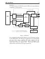
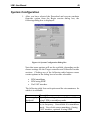
Overview
The target hardware LEM3664 board for HDI has the main hardware
components, as shown below.
I/O Interface Supply
Power
LED
Cable
User
Target
E10T
I/Face
(Reset/ P.S. Monitor/
Target Connected)
Control
SUPERVISOR
I/O
LEVEL
CONVERSION
Enumerator
LED
(Reset/ P.S. Monitor/
Target Connected)
42-Way
Shrink
DIP
Header
Control
Onboard
H8/3664
16 MHz
Oscillator
USB INTERFACE
USB Cable
Evaluation module Board Boundary
Optional – only for use with H8/3664
USB PORT ON
PC
Figure 1: LEM3664
The evaluation module has one USB port, one E10T Interface and one
42-pin SDIP header. The USB port is connected to the corresponding
port on the PC, using a standard USB cable, supplied with the
evaluation module. The E10T interface enables connection to the
target system using the supplied cable. The 42-pin SDIP header
enables direct connection to the target system PCB.
LEM - User Manual
2
7
Installation
System Requirements
Hardware
The minimum hardware configuration, required to install HDI with
the LEM3664, is as follows:
• IBM PC or 100% compatible with a 486 or better. A Pentium
processor is recommended
• 1 free USB port
• 32 MB or more of memory
• Mouse (recommended)
• VGA monitor
• 80 MB of hard disk space
• CD-ROM Drive to install the tools and tutorial files
Software
The operating system for the PC to which the evaluation module will
be connected, must be one of the following:
•
•
•
•
Windows 98
Windows ME
Windows 2000
Windows XP
LEM - User Manual
8
System Specification
MCU Operating Modes
The H8 Tiny series of microcontrollers have a single mode of
operation, supporting a 64 KByte address space.
H8/3664 and 3664N Memory Map
H’0000
H’0400
H’0800
Vector Area
Monitor Code
Free Flash
H’7FFF
H’F780
H’FB80
H’FF80
Monitor Stack/Data
On chip RAM (1 KByte)
Internal I/O Registers
End Of Memory
H’FFFF
Figure 2: H8/3664 Memory Map
LEM - User Manual
9
H8/3672 Memory Map
H’0000
Vector Area
H’0400
Monitor Code
H’0800
Free Flash
H’3FFF
H’F780
Monitor Stack/Data
H’FB80
On chip RAM (1 KByte)
H’FF80
Internal I/O Registers
H’FFFF
End Of Memory
Figure 3: H8/3672 Memory Map
H8/3687 Memory Map
H’0000
H’0400
H’0800
H’DFFF
H’E800
Vector Area
Monitor Code
Free Flash
On Chip RAM
H’EFFF
H’F700
H’F77F
H’FB80
H’FF80
I/O Registers
Monitor Stack/Data
On chip RAM (1 KByte)
Internal I/O Registers
H’FFFF
Figure 4: H8/3687 Memory Map
End Of Memory
LEM - User Manual
10
H8/3694 Memory Map
H’0000
H’0400
H’0800
H’7FFF
H’F730
H’F74F
H’FB80
H’FF80
Vector Area
Monitor Code
Free Flash
I/O Registers
Monitor Stack/Data
On chip RAM (1 KByte)
Internal I/O Registers
H’FFFF
Figure 5: H8/3694 Memory Map
End Of Memory
LEM - User Manual
11
Hardware Installation
The procedure for hardware installation is dependant on whether you
are connecting the low cost evaluation module to a target system
using the external E10T interface or the internal 42-pin SDIP header.
If you are connecting the evaluation module to a target system using
the external E10T interface, use the following procedure:
1. Ensure the target board has a 14-way interface compatible with the
0.1” pitch E10T – Tiny interface header cable used by the
LEM3664. 4K7 pull-up resistors are recommended on each of the
five signals to the H8/Tiny device. The specification of this
interface (serial directions with reference to the target system) is
described in the following table:
Pin
Function
Description
3664F/N,
3687F,
3694F Pin
3672F
Pin
Function
Description
1
3
5
7
SCK
NC
TXD
NMIn
Serial Clock
(Gnd on LEM)
Serial Transmit
Target NMIn
P8_7
P8_6
NMIn
E10_2
E10_1
NMIn
2
4
6
8
GND
GND
GND
UVCC
9
11
13
NC
RXD
RESETn
(Gnd on LEM)
Serial Receive
Target RESETn
P8_5
RESn
E10_0
RESn
10
12
14
GND
GND
UCONNECT
Ground
Ground
Ground
Detect target
supply voltage
Ground
Ground
Detect whether
target connected
3664F/N,
3687F,
3694F &
3672F Pin
Vss
Vss
Vss
Vcc
Vss
Vss
Vss
Table 1: Pin Assignment for the E10T - Tiny Interface
2
14
1
13
Vcc
Vcc
NMIn
NMIn
P8_5
P8_6
P8_7
RESn
P8_5
P8_6
P8_7
RESn
H8/3664F
Device
Vss
14-Way
Connector
User System
Diagram 1: Pin Numbering of Connector on User’s System and Example
Pull-up Resistor Diagram
LEM - User Manual
12
2. Ensure that pin 14 (UCONNECT) is connected to GND on the
target board.
3. Plug one end of the supplied cable into the E10T interface on the
LEM3664.
4. Plug the other end of the supplied cable into a compatible E10T
interface on the target board.
LEM - User Manual
13
If you are connecting the evaluation module to a target system using
the internal 42-pin SDIP header, please note the following:
• The PDIP header is supplied as part of the package for end user
fitting.
• Once the PDIP header has been connected, the LEM3664
circuit board cannot be refitted into its original case. This is to
comply with the requirements of CE conformity.
• Ensure that the target board does not foul the underside of the
LEM3664 circuit board.
• The TEST pin on the PDIP header must be connected to GND.
The procedure for connecting the internal 42-pin SDIP header to a
target system is as follows:
1. Remove the cover of the LEM3664 by gently prising the two case
sections apart. This may be achieved by inserting a flat blade
screwdriver into the holes located at each end of the case.
2. Solder the supplied PDIP header to the circuit board.
3. Connect the LEM3664 evaluation module to the target board using
the 42-way PDIP header, ensuring that the TEST pin is connected
to GND.
LEM - User Manual
14
Software Installation
Software Components
The different software components are:
Hitachi Embedded Workshop
Hitachi Debugging Interface for the LEM3664
CodeLines for the LEM3664
Software Installation Overview
It is recommended that the following installation sequence be
followed:
1.
2.
3.
4.
Installation of Hitachi Embedded Workshop
Installation of HDI3664
Installation of CodeLines 3664
Optional installation of Adobe Acrobat Reader
Note:
The USB driver is installed along with the installation of HDI3664. It
is recommended that the LEM3664 module is not plugged in until the
HDI3664 software has been installed.
LEM - User Manual
15
Installation of Hitachi Embedded Workshop
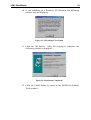
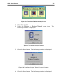
1. Insert the LEM3664 Software Tools CD-ROM. After a few
moments the following window is displayed:
Figure 6: LEM3664 Software Tools Welcome
If this screen does not display automatically, launch the
MENU.EXE program located in the root folder of the CDROM.
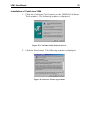
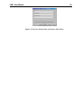
2. Click Install Software. The following window is displayed:
Figure 7: LEM3664 Software Tools Installation Choices
LEM - User Manual
16
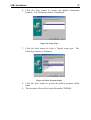
3. Click Hitachi Embedded Workshop. The following window is
displayed:
Figure 8: Installation Welcome screen
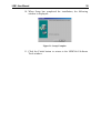
4. Click the Next button. The following window is displayed:
Figure 9: Software License Agreement
LEM - User Manual
17
5. Click the Yes button to indicate your agreement to the
Software License Agreement. The following window is
displayed:
Figure 10: Choose Destination Location
6. Click the Next button. The following window is displayed:
Figure 11: Choose Setup Type
LEM - User Manual
18
7. Leave the Typical option selected and click the Next button.
The following window is displayed:
Figure 12: Select Program Folder
8. Click the Next button to continue. The following window is
displayed:
Figure 13: Start Copying Files
LEM - User Manual
19
9. Click the Next button. File will be copied from the CD-ROM.
After a few moments the following window will be displayed:
Figure 14: Setup Complete
10. Click the Finish button to return to the LEM3664 Software
Tools window.
LEM - User Manual
20
Installation of HDI3664
1. Click the HDI3664 option on the LEM3664 Software Tools
window. The following window is displayed:
Figure 15: HDI3664 Welcome Screen
2. To read the release notes, click the Read Release Notes button,
otherwise, click the Next button. The following window is
displayed:
Figure 16: Software License Agreement
LEM - User Manual
21
3. Click the Next button to indicate your agreement to the
Software License Agreement. The following window is
displayed:
Figure 17: Select Components
4. Click the Next button to install all the components.
following window is displayed:
Figure 18: Additional Information
The
LEM - User Manual
22
5. Click the Next button to accept the default choices.
following window is displayed:
The
Figure 19: Select Destination Directory
6. Click the Next button to accept the default installation
directory. The following window is displayed:
Figure 20: Select Backup Directory
LEM - User Manual
23
7. Click Next to accept the default backup directory.
following window is displayed:
The
Figure 21: Select Start Menu Group
8. Click the Next button to accept the default Start menu group.
The following window is displayed:
Figure 22: Ready to Install!
9. Click the Install button to proceed with the installation.
LEM - User Manual
24
10. If you installing on a Windows 9X platform, the following
window may be displayed:
Figure 23: USB Adapter Not Found
11. Click the OK button. After file copying is complete, the
following window is displayed:
Figure 24: Installation Completed!
12. Click the Finish button to return to the LEM3664 Software
Tools window.
LEM - User Manual
25
Installation of CodeLines 3664
1. Click the CodeLines 3664 option on the LEM3664 Software
Tools window. The following window is displayed:
Figure 25: CodeLines 3664 Welcome Screen
2. Click the Next button. The following window is displayed:
Figure 26: Software License Agreement
LEM - User Manual
26
3. Click the Yes button to indicate your agreement to the
Software License Agreement. The following window is
displayed:
Figure 27: User Information
4. Type your name, company name and product serial number.
You may type any alphanumeric sequence for the serial
number.
5. Click the Next button. The following window is displayed:
Figure 28: Choose Destination Location
LEM - User Manual
27
6. Click the Next button to accept the default destination
location. The following window is displayed:
Figure 29: Setup Type
7. Click the Next button to select a Typical setup type. The
following window is displayed:
Figure 30: Select Program Folder
8. Click the Next button to accept the default program folder
name.
9. The necessary files will be copied from the CD-ROM.
LEM - User Manual
28
10. When Setup has completed the installation, the following
window is displayed:
Figure 31: Setup Complete
11. Click the Finish button to return to the LEM3664 Software
Tools window.
LEM - User Manual
29
Installation of Adobe
Acrobat Reader
Product documentation is supplied as PDF files, requiring Adobe
Acrobat Reader to be installed on your computer. If you do not
already have this program installed on your computer, complete the
following steps:
1. Click the Adobe Acrobat Reader option on the LEM3664
Software Tools window. The following window is displayed:
Figure 32: Acrobat Reader 5.0 Setup
2. Click the Next button. The following window is displayed:
Figure 33: Choose Destination Location
3. Click the Next button to accept the default destination
location.
LEM - User Manual
30
4. The necessary files will be copied from the CD-ROM. When
installation is complete the following window is displayed:
Figure 34: Thank You For Choosing Acrobat Reader!
5. Click the OK button to return to the LEM3664 Software Tools
window.
6. Select the Exit option to close the LEM3664 Software Tools
window.
LEM - User Manual
3
31
LEM Functions
All monitor functions are accessed through the HDI graphical user
interface.
Program Download
The monitor provides HLL debugging capability for the IAR and
Hitachi compilers, which support UBROF V5.0 objects, SYSROF
V1.0 and V2.0 objects, and COFF format without stabs, respectively.
Program Counter Breakpoint
A maximum of 256 breakpoints is supported.
Execution Functions
The different execution modes provided are:
• Execute
1. Run mode
2. Step mode
a)
Step in
b)
Step over
c)
Step out
• Stop
Memory Functions
Memory supporting commands are:
•
•
•
•
General memory set functions
Memory query
Memory get
Fill, verify and verify fill
LEM - User Manual
32
Register Functions
The LEM provides functions that allow retrieval of a CPU register, or
retrieval of all the CPU registers.
Register supporting commands perform:
• Request register block values
• Request single byte register
• Request single long word register
Trace Buffer
The LEM can capture up to four levels of program branch.
Intermediate instructions are filled from a program disassembly
between program branches.
Other Functions
Further commands supported are:
• Definition of LEM capabilities
• Read/Write I/O register
LEM - User Manual
4
33
User Program Considerations
The following gives details on the restrictions placed on the user
program due to the operation of the low cost evaluation module.
Interrupts and Exceptions
Interrupts Used by the Evaluation Module
The evaluation module uses several interrupts to communicate with
the host PC, and control user program execution. The following table
lists the interrupts reserved by the evaluation module:
Vector Number
1
2
3
7*
12
20
Vector address
H’02 to H’03
H’04 to H’05
H’06 to H’07
H’0E to H’0F
H’18 to H’19
H’28 to H’29
Table 2: Interrupts used by the Evaluation module
*Vector 7 is the NMI vector and is utilised in the following two ways:
• It is enabled under supervisor control and is used to break out of
the user program when it is executing.
• It is used by the evaluation module firmware to control execution
of the user program and to report evaluation module status.
• SCI4 (serial communication interface channel 4) is used by the
evaluation module firmware to communicate with the host, via
port pins P87, P86 and P85.
Other Considerations
Standby Modes
The evaluation tool is unable to determine which the mode the
microcontroller is in, i.e. whether the microcontroller is in sleep,
standby or sub-sleep mode.
LEM - User Manual
5
34
Tutorial
This section of the manual will guide you through an example project
building, compiling and debugging session and show the major
features the evaluation module provides, in conjunction with the HDI.
When you have completed this tutorial you will be able to perform
most operations necessary to debug your application. For a complete
description of all standard features available, please refer to the
“Hitachi Debugging Interface - User Manual”.
If you are not using the 3664, then select an alternative timer from the
table below:
If your microcontroller is not included in this table, then no
CodeLines exists for this type and you will not be able to complete
the CodeLines section of the tutorial. Instead, the necessary source
code is included on the LEM3664 CD-ROM.
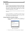
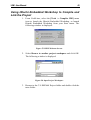
Using CodeLines to Create a Project
1. Launch CodeLines by clicking Start Æ Programs Æ
CodeLines 3664 Æ CodeLines 3664. The following window
is displayed:
Figure 35: Tip Of The Day
2. Click the Close button. The following window is displayed:
LEM - User Manual
35
Figure 36: CodeLines H8/3664 Startup Screen
3. Close this window.
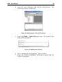
4. Select the [Project -> Project Wizard] menu item.
following window is displayed:
The
Figure 37: CodeLines Project Wizard
5. Click the Next button. The following window is displayed:
Figure 38: CodeLines Project Wizard - Project Creation
6. Click the Next button. The following window is displayed:
LEM - User Manual
36
Figure 39: Project, Header File and Source File Names
LEM - User Manual
37
7. Click the following button to display the Browse dialog box:
8. Navigate to the root of your C: drive. Click the following
button to create a new folder:
9. For the folder name, type LEM3664 Project. Double-click
this newly created folder to open it.
10. In the File name field, type tutor
11. Click the Open button. The CodeLines Project Wizard dialog
box will be re-displayed:
Figure 40: Displaying Project, Header File and Source File Names
12. Click Finish. The following window is displayed:
Figure 41: Project Details
LEM - User Manual
38
13. Click the Next button. The following window is displayed:
Figure 42: Project Details – Main Options
14. Click the Next button. The following window is displayed:
Figure 43: Project Details - Processor Options
15. For the Processor, select HD64F3664BP. Change the Clock
(fc) frequency to 16.0 MHz.
LEM - User Manual
39
16. Click the Next button. The following window is displayed:
Figure 44: Project Details - Interrupts
Click the Next button. The following window is displayed:
Figure 45: Project Details - 300 Compiler Selection
17. Select the IAR TINY compiler and click the Next button. The
following window is displayed:
Figure 46: Project Details - Stack and Heap Sizes
LEM - User Manual
40
18. Change the Stack size to 64 bytes and the Heap size to 32
bytes.
19. Click the Next button. The following window is displayed:
Figure 47: Project Details - Report Generation Options
20. Click the Finish button. The following window is displayed:
Figure 48: CodeLines Project Wizard Has Finished!
LEM - User Manual
41
21. Click the Finish button. The Control, On-chip Peripherals and
External Components windows will be displayed:
Figure 49: CodeLines Control. On-Chip Peripherals and External
Components Windows
22. In the On-chip Peripherals window, locate the Timers section
and double-click Timer V.
23. Click the Pulse Output tab. The following window is
displayed:
Figure 50: Initialisation of the Pulse Output for Timer V
LEM - User Manual
42
24. Click the Add Driver button.
displayed:
The following window is
Figure 51: The Add Driver Dialog Box
25. From the Driver type list, select Pulse Output.
following window is displayed:
Figure 52: Adding the Pulse Output Driver
26. Change the Name for component item to PulseOutput.
The
LEM - User Manual
43
27. Click the OK button. The following window is displayed:
Figure 53: Pulse Output Driver Properties Dialog Box
28. Click the Use all… button, then double-click Pulse output
peripheral. The following window is displayed:
Figure 54: Changing Pulse Output Properties
29. Change the Frequency to 1000 Hz.
30. Change the Lead half-cycle to 10%.
31. Select Lead half-cycle high.
LEM - User Manual
44
32. Click the Initialise Output Pin button. The following window
is displayed:
Figure 55: Initialisation of Output Pin
33. Change the I/O mode to CMOS output. Change the Output
latch to Logic 1. Click the OK button.
34. Clear the Enable interrupt tick box. Click the OK button.
35. The Driver Properties dialog box will be re-displayed.
36. For the pin text type Pulse
37. Click the Close button.
38. Select the [Project -> Build] menu item.
39. The project will be built, with the results of the build being
displayed in the Output window:
Figure 56: Project Build Results
LEM - User Manual
45
Using Hitachi Embedded Workshop to Compile and
Link the Project
1. From CodeLines, select the [Tools -> Compiler IDE] menu
item to launch the Hitachi Embedded Workshop, or launch
Hitachi Embedded Workshop from your Start menu. The
following window is displayed:
Figure 57: HEW Welcome Screen
2. Select Browse to another project workspace and click OK.
The following window is displayed:
Figure 58: Open Project Workspace
3. Browse to the C:\LEM3664 Project folder and double-click the
tutor folder.
LEM - User Manual
46
4. Select the tutor workspace and click the Open button. The
following window is displayed:
Figure 59: Displaying the Tutorial Workspace
5. Select the [Build -> Build All] menu item. The results of the
build will be displayed:
Figure 60: Build Results Window
6. Note a warning may be displayed. This is normal.
7. Close the Hitachi Embedded Workshop program and the
CodeLines program.
LEM - User Manual
47
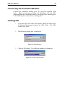
Connecting the Evaluation Module
Connect the evaluation module to the PC using the supplied USB
cable. Both red and green LEDs will illuminate, the red LED
indicating that the evaluation module is receiving power and the green
LED indicating that enumeration is taking place.
Starting HDI
1. To invoke HDI, click Start Æ Programs Æ HDI for LEM 3664
Æ Hitachi Debugging Interface for LEM 3664. The HDI
window will open.
2. The following dialog box is displayed:
Figure 61: Select Session
3. Click the OK button. The following window is displayed:
Figure 62: Create a New Session
LEM - User Manual
48
4. Two options are available on this dialog box:
Figure 63: New Session Options
5. For the purposes of this tutorial, select Download and execute
emulator firmware (the default option).
LEM - User Manual
49
System Configuration
1. After you have selected the Download and execute emulator
firmware option from the Begin session dialog box, the
following dialog box is displayed:
Figure 64: System Configuration Dialog Box
Note that some options will not be available, depending on the
chosen settings for the Target controller and Controller resides
sections. Clicking one of the following radio buttons causes
certain options in the dialog box to become selectable:
• LEM standalone
• LEM using SDIP
• Via E10T interface
The following table lists each option and the circumstances for
which it is available.
Item
Power supply
threshold
Clock
Description
Specify the voltage to be used. Unavailable
using LEM in standalone mode.
Select whether user clock source used and if
so, its frequency. Unavailable if in standalone
mode. User clock source mandatory if using
E10T interface, optional if using SDIP
LEM - User Manual
NMI control
ROM
Single step
interrupts
50
interface.
Select whether the NMI is controlled by
evaluation module or user hardware.
ID code to ‘unlock’ access to the user
program and evaluation module firmware
already resident.
Select whether interrupts are permitted.
Table 3: System Configuration Options
For the purposes of the tutorial, ensure the settings are set to
their default values.
2. Click the OK button to close the System Configuration dialog
box.
3. If communication is successful, the following message will be
displayed on the status bar, at the bottom of the HDI window:
LEM - User Manual
51
Downloading the Tutorial Program
1. Select the [File -> Load Program...] menu option or click the
following toolbar button:
2. The following window is displayed:
Figure 65: Load Program
3. Browse to the C:\LEM3664 Project\tutor\Debug folder and
select the tutor.d20 file.
4. Click the Open button. Several warning messages, similar to
the following, will be displayed. These may be acknowledged
and ignored:
Figure 66: HDI – Reserved Memory Warning
5. After a few moments the following window is displayed:
Figure 67: Confirmation of Areas Loaded
6. Click the OK button.
LEM - User Manual
52
Running the Tutorial Program
Select the [Run -> Reset CPU] menu option, and then select the
[Run -> Go] menu option.
If program execution needs to be verified, attach an oscilloscope to
pin 26 (P76/TMOV) and observe the signal being generated from the
program.
Viewing the program
Changing the program display
The code window can display source level and purely assembly code.
With a C source code window open, click using the right mouse
button. From the short cut menu, click Go to disassembly, to view a
disassembly of the code.
Setting a Program Counter Breakpoint
With a C source code window open, double-click the BP column,
adjacent to the address for which a breakpoint is to be set. The
following black marker will appear, indicating a breakpoint has been
set and is enabled: •. To disable a breakpoint, double-click the
marker, changing its colour from black to red.
Running a Program
To start program execution, select the [Run -> Reset Go] menu
option, press the Shift key and the F5 key, or click the Reset Go
toolbar button:
The Go option may also be used, either by selecting the [Run -> Go]
menu option, pressing the F5 key, or clicking the Go toolbar button:
Note that the program counter must have a valid address. To set the
program counter, left-click the desired code line, click the right mouse
button and select the [Set PC Here] menu option.
LEM - User Manual
53
Running Program to Cursor
A convenient form of running a program is to use the [Go To
Cursor] command. This is achieved by simply setting the cursor
where you want the program to stop. Click the right mouse button
with the mouse pointer in the program window and select [Go To
Cursor] button from the pop-up window menu. Alternatively the
[Run -> Go to Cursor] menu option, or the following toolbar button
may be used to achieve this:
Stopping
When a user program is executing the status bar displays
“RUNNING”. To stop program execution select the [Run -> Halt
Program] menu item, press the ESC key or click the following
toolbar button:
Stepping Over a Function
To step over a C function, select the [Run -> Step Over] menu item
or click the following toolbar button:
Stepping Into a Function
To step into a C function, select the [Run -> Step In] menu item or
click the following toolbar button:
Stepping Out a Function
To step out of a C function, select the [Run -> Step Out] menu item
or click the following toolbar button:
LEM - User Manual
54
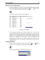
Viewing a Trace of Execution
The chip maintains a list of the last 4 branch instructions executed.
This trace can be viewed by selecting the [View -> Trace] menu
item, or by clicking the following toolbar button:
The following trace window will be displayed:
Figure 68: Trace Window
The instructions marked in the Valid column with ‘*’ are the valid
branch instruction held in chip and through which execution is known
to have passed. All other instructions – those displayed between valid
branches – are interpolated by the LEM software from the known
source code information. Note that in some circumstances the
interpolated code may not be showing the route taken by the
execution between the two branches. In particular it will not show
interrupt code.
Looking at Memory
Memory contents may be viewed by selecting the [View -> Memory]
menu item, or by clicking the following toolbar button:
The following dialog box shown will be displayed:
LEM - User Manual
55
Figure 69: Selecting Memory By Address
The Address entry can be either a pure address or a symbol. A typical
memory window with the data grouped as word, and displayed as hex
and decimal values is shown below:
Figure 70: Memory Window
To edit memory contents, move the mouse cursor to the value you
want to change and double-click to display the following dialog box:
Figure 71: Editing Memory Contents
Type the new value and click the OK button.
What Else Is There?
The other main windows include the System Status, CPU register and
I/O register windows.
System Status
The System Status window details the current setting for the session
including target platform, memory usage and events, i.e. breakpoints.
Open this window by selecting the [View -> Status] menu item or use
following toolbar button:
LEM - User Manual
56
A window similar to the following is displayed:
Figure 72: System Status Session Window
Click the Platform tab to display further status information:
Figure 73: System Status Platform Window
LEM - User Manual
57
CPU Registers
Contents of the CPU registers can be viewed and amended using this
window. Open this window by selecting the [View -> Registers]
menu item or click the following toolbar button:
Figure 74: Registers Window
To edit a register, either double-click the register or right-click the
register and select the [Edit] menu item. The following window will
be displayed, allowing you to enter a new value:
Figure 75: Editing a Register
I/O Registers
Contents of the I/O registers can be viewed and amended using this
window. Open this window by selecting the [View -> I/O Area]
menu item:
Figure 76: I/O Registers Window
LEM - User Manual
58
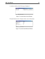
Double-click a device to display its I/O registers:
Figure 77: Displaying Register Contents
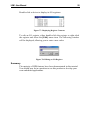
To edit an I/O register, either double-click the register or right-click
the register and select the [Edit] menu item. The following window
will be displayed, allowing you to enter a new value:
Figure 78: Editing an I/O Register
Summary
The majority of HDI features have been demonstrated in this tutorial.
You should now be in a position to use this product to develop your
own embedded applications.
LEM - User Manual
6
59
Menus and Windows
Detailed information on commands and the general HDI functions can
be found in the “Hitachi Debugging Interface - User Manual”.
Windows specific to LEM3664 are as follows:
Select Session
Figure 79: Select Session Window
This window is displayed when the [File -> New Session...] menu
option is selected. From this window you may choose to create a new
session, or load a previously saved session file.
Begin Session
Figure 80: Begin Session Window
This window is displayed when you have chosen to create a new
session. Two options are available on this dialog box:
Figure 81: Begin Session Options
If the Download user program option is selected, a further window is
displayed:
LEM - User Manual
60
Figure 82: Load a File
This window enables you to specify the name of file to be
programmed into the H8/3664, either by typing the name directly or
by clicking the Browse button, locating the program file and clicking
the Open button. Note that the program file must conform to the
Motorola S specification.
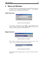
System Configuration
Figure 83: System Configuration Dialog Box
This window is displayed whenever an option is selected on the Begin
Session window, or if the [Setup -> Configure Platform…] menu
option is selected. A full description of the fields available on this
window is given in the Tutorial section of this user manual.
LEM - User Manual
61
Availability of HDI Menu Options
Note that the following HDI menu options are not available when
used with the LEM3664:
View menu
• Performance Analysis Window
• Profile-List
• Profile-Tree
Memory menu
• Configure Map
• Configure Overlay
LEM - User Manual
62
APPENDIX A - Troubleshooting
If the following dialog box is displayed when selecting to create a
new session within HDI, check that the USB cable is connected
between the PC and the evaluation module:
Figure 84: HDI – Unable to Connect
When the cable is connected, click the Yes button to retry
communications. When communications has been established, the
following dialog box will be displayed:
Figure 85: HDI – Begin Session
Select the appropriate option from the list displayed and click the OK
button to continue.
LEM - User Manual
63
Frequently Asked Questions :
1. Stepping over a sleep() instruction causes HDI to run, but pressing
the STOP button may cause an error stating that it cannot stop the
target. HDI will then go link-down and you must restart the target
to get the connection back.
2. Creating a new Session while the disassembly window is displayed
and maximised after a program has stopped running may cause
HDI to close with an error message.
3. Although loading a Session in HDI will upload the program,
pressing GO without first resetting will cause HDI to run into the
monitor code, and not your program. Always make sure that you
reset and then GO after loading a session.
4. Please note that whitespace in the temp file path in Windows 2000
causes problems. This may occur when compiling your first
project. Please check the file names.
5. Stepping through 2 or more instructions when the step rate is set to
slow may cause ‘Command Not Ready’ to be displayed. Increase
the rate value in the Step Program Dialog box to overcome this
issue.
LEM - User Manual
64
APPENDIX B - ASCII Code Table
b b b B
4 3 2 1
b7
0
0
0
0
1
1
1
1
b6
0
0
1
1
0
0
1
1
b5
0
1
0
1
0
1
0
1
MSB/
LSB
0
1
2
3
4
5
6
7
0
0
0
0
0
NUL
DCO
SP
0
@
P
`
P
0
0
0
1
1
SOM
X-ON
!
1
A
Q
a
q
0
0
1
0
2
EOA
TAPE
"
2
B
R
b
r
0
0
1
1
3
EOM
X-OFF
#
3
C
S
c
s
0
1
0
0
4
EOT
$
4
D
T
d
t
0
1
0
1
5
WRU
ERROR
%
5
E
U
e
u
0
1
1
0
6
RU
SYNC
&
6
F
V
f
v
0
1
1
1
7
BEL
LEM
'
7
G
W
g
w
1
0
0
0
8
FE0
CAN
(
8
H
X
h
x
1
0
0
1
9
TAB
S1
)
9
I
Y
i
y
1
0
1
0
A
LF
EOF
*
:
J
Z
j
z
1
0
1
1
B
VT
ESC
+
;
K
{
k
{
1
1
0
0
C
FF
S4
,
<
L
\
l
|
1
1
0
1
d
CR
S5
-
=
M
}
m
}
1
1
1
0
E
SO
S6
.
>
N
^
n
~
1
1
1
1
F
SI
S7
/
?
0
-
o
RUB
OUT