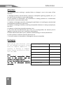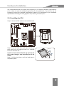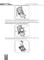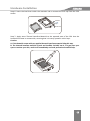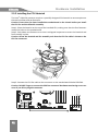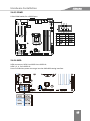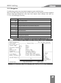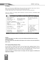
1
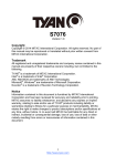
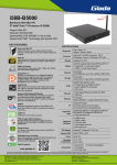
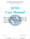
All right reserved
Acknowledgment
Acknowledgment
Dear Giada user,
Thank you very much for choosing Giada server products.
Giada server products are designed for enterprises and households and applied in lots of
areas such as Data storage, Cloud computing, Video surveillance and Cloud storage.
Providing server products with hi-performance and reliable quality is the service principle of
Giada brand.
We provide this detailed User Manual for our products to help you know the product and
operation guidance better. Please read it carefully before installing and using the product.
If you have any problems about the product quality or after-sales service while you using our
products, you can visit our official website for more information, you can find our after sale
service hotline on the website.
Giada’s official website: www.giadatech.com
Copyright & Trademarks
The intellectual property rights of all parts of this product, including all components and software, is
owned by SHENZHEN JEHE TECHNOLOGY DEVELOPMENT CO. , LTD(hereinafter referred to as JEHE) or
the other related parties authorized by JEHE. Without the permission from JEHE, no one can
counterfeit, copy, extract or translate this manual. There is no any form of guarantee, express of
position and hint in this user manual. JEHE and its hired employees will not be responsible for any
data loss, benefit losses or business termination caused by this user manual or the information
mentioned. In addition, JEHE will do their best to ensure the accuracy and completeness of this
manual, but they will not guarantee there is no error in this manual since the product may upgrade in
future. JEHE will not guarantee any typographical errors in this manual or be responsible for any
misunderstanding by users. JEHE may make changes to the specifications and product descriptions at
any time without further notice.
The product names that mentioned in this manual is for recognition only. These names may be
registered trademarks or property belonged to some other companies.
Giada® is a registered trademark owned by SHENZHEN JEHE TECHNOLOGY DEVELOPMENT CO. , LTD.
Windows® , MS® , MS-DOS® , Windows Vista® and Windows7® are registered trademarks owned by
Microsoft Corporation.
Intel® Xeon® , Intel® AtomTM, Intel® Celeron® , Intel® CoreTM are registered trademarks owned by
Intel Corporation.
For the latest product specifications or information, please visit our official website or contact with us
directly.
1
Attention
Attention
The following factors resulting in product failure or damage is not in the scope of free
warranty:
A. Damages caused by natural disaster ( flood, fire, earthquake, lightning, typhoon, etc. ), or
any event of force majeure or man-made damage.
B. Self assemble or disassemble, self repairment or sending products to a maintenance
station which is not authorized by JEHE.
C. Problems or damages caused by changing the specification or installing any unauthorized
extended device arbitrarily by the users.
D. Problems or damages caused by installing incompatible softwares or setting improperly by
the users.
E. Problems or faults that caused by computer virus.
F. The event that the identification tag is tear up or unrecognizable, the warranty card is
juggled or warranty card is not in conformity with products.
G. Install software that offer by user, software troubleshooting or remove password etc.
H. Other problems and faults caused by abnormal use.
I. The serial number in the products is damaged or cannot be identified.
Packaging
After you get this board box, check
all the standard accessories listed
below are complete immediately. If
anything is missing or damaged,
please contact your dealer or direct
sale and JIEHE
Accessories Category
Quantity
Motherboard
1
SATA cable
2
I/O back barrier-plate
1
Note:
a, practical accessories please
refer to the product type and
quantity of packing prevail.
b, save the packing and accessories
for use in subsequent service
processes.
CD
1
User Manual
1
Product certification
1
Quality Assurance Card
1
2
Catalog
Catalog
Acknowledgment ___________________________________________________________ 1
Copyright & Trademarks ______________________________________________________ 1
Attention __________________________________________________________________ 2
Catalog ___________________________________________________________________ 3
Chapter 1 Product Features ___________________________________________________ 4
1.1 Safety Information ____________________________________________________________ 4
1.2 Product Specification __________________________________________________________ 5
1.3 Product Highlights ____________________________________________________________ 6
Chapter 2 Hardware Installation _______________________________________________ 7
2.1 Installation Precautions ________________________________________________________ 7
2.2 Motherboard Layout __________________________________________________________ 8
2.3 Installing the CPU and CPU Cooler _______________________________________________ 8
2.4 Installing the Memory ________________________________________________________ 14
2.5 Rear Panel Connectors ________________________________________________________ 16
2.6 Internal Connectors __________________________________________________________ 17
Chapter 3 BIOS Setting ______________________________________________________ 26
3.1 Starting BIOS _______________________________________________________________ 26
3.2 Main ______________________________________________________________________ 28
3.3 Advanced __________________________________________________________________ 29
3.4 Chipset ____________________________________________________________________ 43
3.5 Boot ______________________________________________________________________ 51
3.6 Security ___________________________________________________________________ 55
3.7 Save and Exit _______________________________________________________________ 56
3.8 Event Logs _________________________________________________________________ 57
Chapter 4 Appendix _______________________________________________________ 60
3
Product Features
Chapter 1 Product Features
1.1 Safety Information
1.1.1 Safety of Electric
A. To avoid damage of electric shock, please turn off the power and unplug the power cord
before moving the computer.
B. Before you add or remove any component or extended device, do turn off the power and
unplug the power cord; After complete installing of device, please plug the data cable before
you turn on your computer.
C. Please ask a professional help before installing any extended device. Please use the
regulated components specified in this manual, other components may cause some
compatibility problems.
D. Please make sure the power supply voltage setting has been adjusted to the standard used
in your country. If you are not sure what voltage is used in your living area, please ask the
nearest local power company for help.
E. Do not try to fix the power supply by yourself once it fails to work. Please ask a
professional service staff or the dealer for help.
1.1.2 Safety of Operation
A. Please read the manual carefully and follow the instructions that mentioned in this
manual when you want to install any extended device to the motherboard.
B. Make sure all date cables, connectors and power cord has been correctly plugged in before
you turn on the system. If you find any severe defects, please contact your dealer as soon as
possible.
C. To avoid electrical short, do not leave any useless screws、needles and other metal parts
on the motherboard.
D. Dust, moisture and severe temperature changes will affect the life of the motherboard, so
please avoid place your computer in these areas.
E. Keep the computer in a stable environment, a shaky environment may cause physical
damage.
F. If you have any technical question during using this product, please contact our technical
engineer for help.
4
Product Features
1.2 Product Specification
SIZE
CPU
Chipset
BMC
I/O Controller
Memory
LAN
Graphics
Micro ATX 9.6 in. x 9.6 in.
Supports the latest Intel® Xeon® Processors E3 v3 Family
Supports the 4th Generation Intel® Core™ i3 Processors
Intel® C222 PCH
N/A
Nuvoton NCT6791D
Supports ECC DDR3/DDR3L 1333/1600 MHz
Supports Dual-channel, 4 UDIMM slots, up to 32GB
2 x Intel® LAN Controller supports 10/100/1000Mbps
ASPEED® AST1400 with 128MB VRAM
4 x SATA 3Gb/s connectors
2 x SATA 6Gb/s connectors
Storage Interface
Supports SATA HDD and SSD
Supports Raid (Software Raid)
Supports Raid card for extension
1 x PCI Express 2. 0 x8 slot running at 4X
Expansion Slots
1 x PCI Express 3. 0 x8 slot running at 8X
1 x PCI Express 3. 0 x16 slot running at 8X
2 x SATA 6Gb/s connectors for storage
4 x SATA 3Gb/s connectors for storage
5 x 4 pin FAN headers for CPU and system
1 x 20pin TPM header for security
Internal Connectors
1 x 4-pin ATX header for power
1 x 24-pin ATX header for power
1 x 9-pin COM header
1 x 19-pin USB 3. 0 header
1 x 9-pin USB 2. 0 header
1 x USB 3. 0 port
4 x USB 2. 0 ports
Rear Panel
1 x VGA port
1 x COM port
2 x RJ45 port
BIOS
OS Support
AMI BIOS
Windows and Linux
Caution: Giada reserves the right to make any changes to the product specifications and
product related information without prior notice.
5
Product Features
1.3 Product Highlights
Latest Processor Technology
N30M series motherboard supports the latest Intel® Xeon® Processor E3-1200 v3 Family /
CoreTM i3 series in LGA1150 package, which has memory and PCI Express controller
integrated to support 2-channel (4 DIMMs) DDR3/DDR3L memory and 16 PCI Express 3. 0
lanes. The Intel® Xeon® E3-1200 v3 has improved CPU performance and integrated voltage
regulators making it one of the most powerful and energy efficient CPU in the world.
Intel® Turbo Boost
Intel® Turbo Boost automatically allows the processor to run faster than the marked
frequency if the processor is operating below its power, current, and temperature
specification limits. This technology increase performance of both multi-threaded and
single-threaded workloads.
Intel® Hyper Threading
The thread-level parallelism on each processor makes more efficient use of the processor
resource, higher processing throughout and improved performance on today’s
multi-threaded software.
DDR3/DDR3L Memory Support
N30M series motherboard supports ECC UDIMM DDR3/DDR3L memory that features data
transfer rates of 1600/1333 MHz to meet the higher bandwidth requirements of server and
workstation applications. The dual-channel DDR3 architecture boosts system performance,
eliminates bottlenecks with a peak bandwidth up to 25Gb/s, and dramatically reduces the
memory voltage to just 1. 5V/1. 35V compared to DDR2’s memory voltage of 1. 8V.
Intel® i210AT / i218LM dual NIC Network Solutions
N30M series motherboard has two Gigabit LAN controllers and network port to provide a
complete solution to meet the needs of your network using the built-in Intel® i210AT /
i218LM dual Gigabit LAN controller, use the PCI Express interface, you can reach close to
Gigabit bandwidth network connections.
USB 3. 0 Technology
N30M series motherboard implements the USB 3. 0 technology with data transfer speeds of
up to 5Gbps, faster charging time fro USB-chargeable devices, optimized power efficiency,
and backward compatibility with USB 2. 0.
Serial ATA 6 Gb/s Technology
N30M series motherboard supports the Serial ATA 6 Gb/s technology through the Serial ATA
interface and Intel® C22x chipset. Get enhanced scalability, faster data retrieval, double the
bandwidth of current bus systems with up to 6Gbps data tranfer rates.
6
Hardware Installation
Chapter 2 Hardware Installation
2.1 Installation Precautions
The motherboard contains numerous delicate electronic circuits and components which can
become damaged as a result of electrostatic discharge (ESD). Prior to installation, carefully
read the user's manual and follow these procedures:
A. Prior to installation, do not remove or break motherboard S/N (Serial Number) sticker
orwarranty sticker provided by your dealer. These stickers are required for warranty
validation.
B. Always remove the AC power by unplugging the power cord from the power outlet before
installing or removing the motherboard or other hardware components.
C. When connecting hardware components to the internal connectors on the motherboard,
make sure they are connected tightly and securely.
When handling the motherboard, avoid touching any metal leads or connectors.
D. It is best to wear an electrostatic discharge (ESD) wrist strap when handling electronic
components such as a motherboard, CPU or memory. If you do not have an ESD wrist strap,
keep your hands dry and first touch a metal object to eliminate static electricity.
E. Prior to installing the motherboard, please have it on top of an antistatic pad or within an
electrostatic shielding container.
F. Before unplugging the power supply cable from the motherboard, make sure the power
supply has been turned off.
G. Before turning on the power, make sure the power supply voltage has been set according
to the local voltage standard.
H. Before using the product, please verify that all cables and power connectors of your
hardware components are connected.
I. To prevent damage to the motherboard, do not allow screws to come in contact with the
motherboard circuit or its components.
J. Make sure there are no leftover screws or metal components placed on the motherboard
or within the computer casing.
K. Do not place the computer system on an uneven surface.
L. Do not place the computer system in a high-temperature environment.
M. Turning on the computer power during the installation process can lead to damage to
system components as well as physical harm to the user.
N. If you are uncertain about any installation steps or have a problem related to the use of
the product, please consult a certified computer technician.
7
Hardware Installation
2.2 Motherboard Layout
2.3 Installing the CPU and CPU Cooler
Read the following guidelines before you begin to install the CPU:
A. Make sure that the motherboard supports the CPU.
B. Always turn off the computer and unplug the power cord from the power outlet before
installing the CPU to prevent hardware damage.
C. Locate the pin one of the CPU. The CPU cannot be inserted if oriented incorrectly. (Or you
may locate the notches on both sides of the CPU and alignment keys on the CPU socket. )
D. Apply an even and thin layer of thermal grease on the surface of the CPU.
E. Do not turn on the computer if the CPU cooler is not installed, otherwise overheating and
damage of the CPU may occur.
F. Set the CPU host frequency in accordance with the CPU specifications. It is
8
Hardware Installation
not recommended that the system bus frequency be set beyond hardware specifications
since it does not meet the standard requirements for the peripherals. If you wish to set the
frequency beyond the standard specifications, please do so according to your hardware
specifications including the CPU, graphics card, memory, hard drive, etc.
2.3.1 Installing the CPU
Step 1: Locate the CPU socket on the motherboard.
Step 2: Press the load lever with your thumb (A),
then move it to the right (B) until it is released
from the retention tab.
Caution: Do not remove the PnP cap yet from the
CPU socket. Doing so may bend the pins of the
socket.
Step 3: Lift the load lever until the load plate is
completely lifted.
Load lever
Retention tab
9
Hardware Installation
Load pate
Step 4: Position the CPU above the socket, ensuring that the gold triangle mark is on the
bottom-left corner of the socket, then fit the CPU notches to the socket’s alignment keys.
Caution: The CPU fits in only one orientation. DO NOT force the CPU into the socket to
prevent bending the pins on the socket and damaging the CPU.
CPU notches
Gold
triangle
mark
Alignment
Key
Alignment
Key
Step 5: Close the load plate (step A), ensuring that the front edge of the load plate slides
under the retention lock(B) then push down the load lever(C).
Load lever
Retention
lock
10
Hardware Installation
Step 6: Insert the load lever under the retention tab to remove the PnP cap from the CPU
socket.
Load lever
Retention tab
Step 7: Apply some Thermal Interface Material to the exposed area of the CPU that the
heatsink will come in contact with, ensuring that it is evenly spread in a thin layer.
Caution:
A. If the heatsink comes with pre-applied thermal interfacee material skip this step.
B. The thermal interface material is toxic and inedible. DO NOT eat it. If it gets into your
eyes or touches your skin, wash it off immediately and seek professional medical help.
11
Hardware Installation
2.3.2 Installing the CPU Heatsink
The Intel® LGA1150 processor requires a speciallly designed CPU heatsink to ensure optimum
thermal condition and performance.
Caution: Ensure that you have installed the motherboard to the chassis before you install
the CPU fan and the heatsink assembly.
Step 1: Place the heatsink on the top of the installed CPU, making sure that the four fasteners
match the holes on the motherboard.
Step 2: Push down two fasteners at a time in a diagonal sequence to secure the heatsink and
fan assembly in place.
Caution: Orient the heatsink and fan assembly such that the CPU fan cable is closest to the
CPU fan connector.
Step 3: Connect the CPU fan cable to the connector on the motherboard labeled CPUFAN.
Caution: DO NOT forget to connect the CPU fan connector! Hardware monitoring errors can
occur if you fail to plug this connector.
12
CPU_FAN_CTL
CPU_FAN_TAC
GND
+12V
CPUFAN
Hardware Installation
2.3.3 Uninstalling the CPU Heatsink and Fan
To uninstall the CPU heatsink and fan:
Step 1: Disconnect the CPU fan cable from the connector on the motherboard.
Step 2: Rotate each fastener counterclockwise.
Step 3: Pull up two fasteners at a time in a diagonal sequence to disengage the heatsink and
fan assembly from the motherboard.
A
B
B
A
Step 4: Carefully remove the heatsink and fan assembly from the motherboard.
2.3.4 Installing the CPU Heatsink in a Rack
Step 1: Peel off the sticker on the heatsink metal plate and affix the plate to the back of the
motherboard, matching the standoffs to the heatsink screw holes.
Step 2: Use a Phillips screwdriver to tighten the four heatsink screws using the recommended
13
Hardware Installation
sequence below.
Caution:
A. Ensure that the heatsink is not skewed or titted otherwise the CPU will overheat.
B. DO NOT overtighten the screws. Doing so can damage the CPU.
2.4 Installing the Memory
Read the following guidelines before you begin to install the memory:
A. Make sure that the motherboard supports the memory. It is recommended that memory
of the same capacity, brand, speed, and chips be used.
B. Always turn off the computer and unplug the power cord from the power outlet before
installing the memory to prevent hardware damage.
C. Memory modules have a foolproof design. A memory module can be installed in only one
direction. If you are unable to insert the memory, switch the direction.
2.4.1 Dual Channel Memory Configuration
This motherboard provides four DDR3 memory sockets and supports Dual Channel
Technology. When the memory is installed, the BIOS will automatically detect the
specifications and capacity of the memory.
Enabling Dual Channel memory mode will double the original memory bandwidth.
The four DDR3 memory sockets are divided into two channels and each channel has two
memory sockets as following:
Channel 1: DIMM1, DIMM2
Channel 2: DIMM3, DIMM4
14
Hardware Installation
DIMM4
DIMM3
DIMM2
DIMM1
Due to CPU limitations, read the following guidelines before installing the memory in Dual
Channel mode.
A. Dual Channel mode cannot be enabled if only one DDR3 memory module is installed.
B. When enabling Dual Channel mode with two or four memory modules, it is recommended
that memory of the same capacity, brand, speed, and chips be used for optimum
performance.
C. If you install only one DIMM, please install in DIMM4;
If you install two DIMMs, please install in DIMM4&3 or DIMM4&2;
If you want to install three DIMMs, please install in DIMM4&3&2;
If you want to install four DIMMs, please install in DIMM4&3&2&1.
2.4.2 Installing a Memory
Installation Step:
Step 1. Insert the DIMM memory module vertically
into the DIMM slot, and push it down.
Step 2. Close the plastic clip at both edges of the
DIMM slots to lock the DIMM module.
Caution:
A. NOTE! DIMM must be populated in order starting
from DIMM4 socket.
B. For dual-channel operation, DIMMs must be
installed in matched pairs.
Reverse the installation steps when you wish to
remove the DIMM module.
2
1
2
15
Hardware Installation
2.5 Rear Panel Connectors
1, Serial Port (COM)
Connects to serial-based mouse or data processing devices.
2 / 3, USB Port
The USB port supports the USB 2. 0 specification. Use this port for USB devices such as a USB
keyboard/mouse, USB printer, USB flash drive and etc.
4 / 5, RJ-45 LAN Port
The Gigabit Ethernet LAN port provides Internet connection at up to 1 Gbps data rate.
6, VGA Port
The VGA in port allows connect to video in, which can also apply to video loop
thru function.
16
Hardware Installation
2.6 Internal Connectors
Read the following guidelines before connecting external devices:
A. First make sure your devices are compliant with the connectors you wish to connect.
B. Before installing the devices, be sure to turn off the devices and your computer. Unplug
the power cord from the power outlet to prevent damage to the devices.
C. After installing the device and before turning on the computer, make sure the device cable
hasbeen securely attached to the connector on the motherboard.
17
Hardware Installation
2.6.1 JPG1
VGA switch
Pin 1-2: enable VGA out(default); Pin 2-3: disable VGA out.
2.6.2 JI2C_C/D
PCIE Slot SMB switch
With jumper cap: enabled; Without jumper cap: disabled(default).
18
Hardware Installation
2.6.3 F_USB2_1
USB 2. 0 header offer two USB 2.0 interfaces.
2.6.4 F_USB3-1
USB 3.0 header, offer one USB3.0 interface, only Pin 1~10 are valid.
19
Hardware Installation
2.6.5 TPM_HEADER1
TPM header is used to connect a Trusted Platform Module(TPM is a third party device can be
plugged into this board providing protection for your PC, BIOS, OS and net connection, etc. ).
2.6.6 LPC_CON1
LPC header, used for connection LPC I/O device.
20
Hardware Installation
2.6.7 CLR_CMOS
CMOS clear,
Pin 1-2: keep CMOS (default);
Pin 2-3: clean CMOS (do not try if you are not professional).
2.6.8 SATA_PWR1
Used to provide power to SATA interface.
21
Hardware Installation
2.6.9 FAN
Headers For CPU fan and system fans, supports 5 fans maximum.
2.6.10 JF1
Jumpers for the front panel, they can be connected to the power button and instruction LED.
22
Hardware Installation
2.6.11 JD1
Jumpers for External LED and Buzzer
Pin 1-3 for Power LED;
Pin 4-7 for external buzzer;
Pin 6-7 for internal buzzer, default 6-7 with cap.
2.6.12 ME_UPD
BIOS protection
Pin 1-2: disable, BIOS cannot be upgraded;
Pin 2-3: enable, BIOS can be upgraded(default).
23
Hardware Installation
2.6.13 J1
2V PCI-E1 power supply header, it offers extra power for PCIE1 device when the consumption
is more than 70W.
1
2
3
4
+12V
GND
GND
NO
2.6.14 AUTOPW_ON
Auto power on switch
Pin 1-2: enable auto power on, when the system is connected with an operative power
supply;
Pin 2-3: Disable auto power on, you need to press the power button the start the system
(default).
24
Hardware Installation
2.6.15 COM2
9 Pins COM header, for a RS232 port.
2.6.16 SATA
SATA connectors, SATA 0 and SATA 1 are SATA3.0;
SATA 2, 3, 4, 5 are SATA2.0;
Press Ctrl+M when power on can go into the RAID DOS setting interface.
25
BIOS Setting
Chapter 3 BIOS Setting
BIOS (Basic Input and Output System) records hardware parameters and other system
configuration of the system on the motherboard. Its major functions include conducting the
Power-On Self-Test (POST) during system startup, saving system parameters and loading
operating system, etc. BIOS includes a BIOS Setup program thatallows the user to modify
basic system configuration settings or to activate certain system features.
BIOS flashing is potentially risky, if you do not encounter problems of using the current BIOS
version, it is recommended that you don't flash the BIOS. To flash the BIOS, do it with caution.
Inadequate BIOS flashing may result in system malfunction.
It is recommended that you not alter the default settings (unless you need to) to prevent
system instability or other unexpected results. Inadequately altering the settings may result
in system's failure to boot. If this occurs,try to clear the current values via the related jumper
or removing the battery on M/B, then power on system to load default values.
3.1 Starting BIOS
The chapter describes the basic navigation of the BOIS setup screens, to enter the BOIS setup
screens, please refer to the following steps.
Step
1
2
3
Description
Power on the motherboard.
Press the <Delete> key on your keyboard when you see the following text prompt
as “Press Del or Esc to enter setup”.
After you press <Delete> key, the BOISsetup menu displays, you can access the
other setup screen from the main BIOS setup menu, such as the Advanced and
boot menus.
3.1.1 Setup Menu
The BIOS setup menu is the first screen that you can navigate. Each BIOS setup menu menu
option is described in this manual.
The BIOS setup menu has two main frames. The left frame displays some Options that can be
configured. Some item options cannot be configured. It is only tell user about the
configuration information or useful information.
The right frame displays the key legend. Above the key legend is an area reserved for a Text
message. When an option is selected in the left frame, it is highlighted in white. Often a help
message will accompany it.
26
BIOS Setting
3.1.2 Navigation
The BIOS setup utility uses a key-based navigation system called hot keys.
Most of the BIOS setup utility hot keys can be used at any time during the setup navigation
process. These keys include <F1>, <F2>, <F3>, <F4>, <Enter>, <Esc>, <Arrow>, <K>, <M>, <+>,
<->, etc. The following are hot keys.
Hot Key
Description
→←
Select a setup screen.
↑↓
Select a setup item or sub-screen.
Enter
+/-
Selected.
Change the field value of a particular setup item.
F1
General Help.
F2
Previous Values.
F3
Optimized Default.
F4
Save & Exit.
Esc
K
M
Exit.
Scroll help area upwards.
Scroll help area downwards.
27
BIOS Setting
3.2 Main
When you first enter the BIOS Setup Utility, you will enter the Main setup screen. You can
always return to the Main setup screen by selecting the Main tab.
The Main BIOS Setup screen is shown below. In this menu, there are some item
value isn’t change, for example, BIOS information, Processor, Memory, Embedded VBIOS
information and so on.
Caution:
A. When the system is not stable as usual, select the Restore Defaults item to set your
system to its defaults.
B. The BIOS Setup menus described in this chapter are for reference only and may differ by
BIOS version.
3.2.1 System Date/System Time
Use this option to change the System Time and System Date. Highlight System Time or
System Date using the <Arrow> keys. Enter new values through the keyboard. Press the
<Tab> and <Shift-Tab> Key or the <Arrow> keys to move between fields. The date must be
entered in MM/DD/YYYY format. The time is entered in HH:MM:SS format.
Caution: The time is in 24-hour format. For example, 5:30 A.M. appears as 05:30:00, and
5:30, P.M. as 17:30:00.
28
BIOS Setting
3.3 Advanced
The Advanced menu display submenu options for configuring the function of various
hardware components. Select a submenu item, then press Enter to access the related
submenu screen.
3.3.1 PCI Subsystem Settings
VGA Palette Snoop
Enable/Disable VGA Palette Registers Snooping to support both ISA and PCI Video card at the
same time. Options available: Enabled/Disabled. Default setting is [Disabled].
PERR# Generation
When this item is set to enabled, when PCI bus data parity error (PERR) is generated, system
will implement related error logging and reporting. Options available: Enabled/Disabled .
Default setting is [Disabled].
SERR# Generation
When this item is set to enabled, when PCI bus system error (SERR) is generated, system will
implement related error logging and reporting. Options available: Enabled/Disabled. Default
setting is [Disabled].
29
BIOS Setting
3.3.2 ACPI Configuration
Enable Hibernation
System hibernate (S4), the default setting is [Enabled].
WHEA Support
Select Enabled to support Windows Hardware Error Architecture (WHEA) on Microsoft
Windows 2008 (or a later vision) operating system. The default setting is [Enabled].
30
BIOS Setting
3.3.3 Trusted Computing
This option specifies TPM; The setup default setting is [Disabled]. If you have installed an
extend TPM module, you can find the detail TPM setting options here.
3.3.4 CPU Configuration
The CPU Configuration setup screen varies depending on the installed processor.
Hyper-Threading
Select Enabled to support Intel Hyper-threading Technology to enhance CPU performance.
The default setting is [Enabled].
Active Processor Core
This feature determines how many CPU cores will be activated for each CPU. When all is
selected, all cores in the CPU will be activated. The default setting is [All].
Execute Disable Bit
Set to Enabled to enable the Execute Disable Bit which will allow the processor to designate
areas in the system memory where an application code can execute and where it cannot,
thus preventing a worm or a virus from flooding illegal codes to overwhelm the processor or
damage the system during an attack. The default is [Enabled].
Intel Virtualization
Select Enabled to use the Intel Virtualization Technology to allow one platform to run
multiple operating systems and applications in independent partitions, creating multiple
"virtual" systems in one physical computer. The default setting is [Enabled].
Hardware Prefetcher
If set to Enabled, the hardware prefetcher will prefetch streams of data and instructions from
the main memory to the L2 cache to improve CPU performance. The default setting is
31
BIOS Setting
[Enabled].
Adjacent Cache Line Prefetch
Select Enabled for the CPU to prefetch both cache lines for 128 bytes as comprised. Select
Disabled for the CPU to prefetch both cache lines for 64 bytes. The default setting is
[Enabled].
CPU AES
Select Enabled to enable Intel® CPU Advanced Encryption Standard (AES) Instructions for
CPU to enhance data integrity. The default setting is [Enabled].
EIST
EIST (Enhanced Intel SpeedStep Technology) allows the system to automatically adjust
processor voltage and core frequency in an effort to reduce power consumption and heat
dissipation. Please refer to Intel’s web site for detailed information. The default setting is
[Enabled].
Turbo Mode
Select Enabled to allow processor cores to run faster than the frequency recommended by
the manufacturer. The default setting is [Enabled].
For Boot Performance Mode, Energy Performance, VR Current value, CPU C states, ect. These
options are Related to the performance of the system please keep the default setting.
32
BIOS Setting
33
BIOS Setting
3.3.5 SATA Configuration
SATA Controller
This item Enables or Disables the built-in SATA controllers on the motherboard. The default
setting is [Enabled].
SATA Mode Select
This item selects the SATA mode for a device installed on a SATA drive. The default setting is
[AHCI].
Port 0 / 1 / 2
This feature is uesed to enable or disable the SATA port. The default settiong is [Enabled];
Spin Up Device
On an edge detect from 0 to 1, set this item to allow the PCH to start a COMRESET
initialization sequence to the device. The options are Enabled and Disabled.
SATA Device Type
This feature configures the selected SATA port to support either a solid state drive or hard
disk drive. The options are Hard Disk Drive and Solid Sate Drive.
34
BIOS Setting
3.3.5.1 SATA Mode Selection
Select the on chip SATA type.
IDE Mode: When set to IDE, the SATA controller disables its RAID and AHCI functions and
runs in the IDE emulation mode. This is not allowed to access RAID setup utility.
RAID Mode: When set to RAID, the SATA controllerenables both its RAID and AHCI functions.
You will be allows access the RAID setup utility at boot time.
ACHI Mode: When set to AHCI, the SATA controller enables its AHCI
functionality. Then the RAID function is disabled and cannot be access the RAID setup utility
at boot time.
Options available: IDE/RAID/ACHI/Disabled. Default setting is ACHI Mode.
3.3.5.2 Software Feature Mask Configuration
In this items, you can disable and enable some SATA Specific feature.
35
BIOS Setting
3.3.6 USB Configuration
Legacy USB Support
Enables or disables support for legacy USB devices.
Options available: Auto/Enabled/Disabled. Default setting is [Enabled].
XHCI Hand-off
Enable/Disable XHCI (USB 3.0) Hand-off support.
Options available: Enabled/Disabled. Default setting is [Enabled].
EHCI Hand-off
Enable/Disable EHCI (USB 2.0) Hand-off function.
Options available: Enabled/Disabled. Default setting is [Enabled].
USB Mass Storage Driver Support
Enable/Disable USB Mass Storage Driver Support.
Options available: Enabled/Disabled. Default setting is [Enabled].
Port 60/64 Emulation
Enable I/O port 60h/64h emulation support. This should be enabled for the complete USB
Keyboard Legacy support for non-USB aware OS.
Options available: Enabled/Disabled. Default setting is [Disabled].
USB Hardware delays and time-outs
There are three USB time-out options to control and enhance the USB data transfer and USB
device initialize settings.
Caution: When you install USB storage, there will display USB Mass Device Configuration
item, from this item, you can get some information about the device.
36
BIOS Setting
3.3.7 NCT6791D Super IO Configuration
This menu show NET6791D SIO HWM, UARTs base information and related function settings.
3.3.7.1 NCT6791D HW Monitor
This menu shows the whole system Temperature, Fan, Voltage information.
37
BIOS Setting
3.3.7.2 Fan Speed Configuration
This option specifies the CPU and System fan settings. The Default setting is [Smart fan
mode].
3.3.7.3 Serial Port 0 Configuration
This option specifies the base I/O port address and Interrupt Request of serial Port 1. The
Optimal setting is [IO=3F8, IRQ=4].
38
BIOS Setting
3.3.7.4 Serial Port 1 Configuration
Please refer to Serial Port0 Configuration for this option. The Default setting is [IO=2F8,
IRQ=3].
3.3.7.5 System Power Loss
The AC power Restore setting after power lost. The default setting is [Last State].
3.3.8 Serial Console Redirection Configuration
You can select console redirection in the left frame of the screen to go to the sub menu for
that item. You can display a console redirection by highlighting it using the <Arrow> keys.
Console redirection setup options are described in this section. The console redirection BIOS
setup screen is shown below.
39
BIOS Setting
3.3.8.1 Console Redirection Feature
The option specifies console redirection. When you enable this item you will get the detailed
information for the serial port, the optimal setting is disabled. The setup default is [Disabled].
Option
40
Description
Disabled
This value prevent you configure Serial Console Redirection.
Enabled
Enable Serial Console Redirection
BIOS Setting
3.3.8.2 EMS Console Support
EMS is an Microsoft Emergency Management Service, Microsoft use this feature to remote
control system when the system LAN is not available. The option specifies EMS Support.
Setup default is [Disabled].
Out-of-Band Mgmt Port
Option
Description
COM1
Use the COM1 port as EMS, default option;
COM2
Use the COM2 port as EMS.
Terminal Type
The option specifies console types in the serial port. There are four types standard, VT100,
VT100+, ANSI and VT-UTF8.
Option
Description
VT100
ASCII Char set.
VT100+
Extends VT100 to support color function, etc.
ANSI
Extended ASCII char set.
VT-UTF8
Uses UTF8 encoding to map Unicode chars onto 1 or more.
Bits per Second
The option specifies serial port transmission speed. The speed must be matched on the other
side. Long or noisy lines may require lower speeds. Through this item you can select the baud
rate you want the serial port to use for console redirection.
41
BIOS Setting
Option
Description
115200
Selects serial port Baud rate as 115200.
57600
Selects serial port Baud rate as 57600.
19200
Selects serial port Baud rate as 19200.
9600
Selects serial port Baud rate as 9600.
Flow Control
The option specifies Flow Control. The optimal setting is none. The setup default is None.
Option
None
Hardware
Description
Set this value to disable Flow control.
Select this value to make Flow control by Hardware.
RTS/CTS
Software
Select this value to make Flow control by Software.
Xon/Xoff
3.3.8.3 Network Stack Configuration
Network Stack: Enable or disable UEFI Network Stack, Ipv4/Ipv6 PXE function enable or
disable, the default setting is [Disable].
42
BIOS Setting
3.4 Chipset
Select the Chipset tab from the BIOS setup screen to enter the Chipset Setup screen. You can
select any of the items in the left frame of the screen, such as PCH-IO Configuration, SA
configuration, to go to the sub menu for that item. You can display a Chipset Setup option by
highlighting it using the <Arrow> keys. You can use <+> and <-> moves the device up or down.
The Chipset setup screen is shown below.
43
BIOS Setting
3.4.1 PCH-IO Configuration
Use this screen to specify the PCH PCI/PCIE and USB configuration. To access these sub
screens, press <Enter>, the following screen display.
3.4.1.1 PCI/PCI-Express Configuration
Use this screen to specify the PCH PCI or PCI Express device Control option. Press <Enter> to
access these screens.
DMI Link ASPM Control
The control of Active State Power Management on both NB side and SB side of the DMI Link.
Options available: Enabled/Disabled. The default setting is [Disabled].
PCIe-USB Glitch W/A
PCIe-USB Glitch W/A for bad USB device(s) connected behind PCIE/PEG Port.
Options available: Enabled/Disabled. The default setting is [Disabled].
ntel I210 LAN Control
Control embedded I210 LAN controller, the default is Disabled.
Intel I218 LAN Control
Control embedded I218 LAN controller, the default is Disabled.
Wake on LAN
Control the Embedded I210 and I218 LAN WOL function, the default is Disabled.
PCIE Port5 – PCH Slot4
In the sub menu, there are Port, ASPM, Speed and compliance detection options on Slot4
that is connect to PCH PCI Express Root Port 5.
44
BIOS Setting
3.4.1.2 USB Configuration
USB Precondition
Precondition work on USB host controller and root ports for faster enumeration.
Options available: Enabled/Disabled. The default setting is [Disabled].
XHCI Mode
Mode of operation of xHCI controller.
Options available: Smart Auto/Auto/Enabled/Disabled/Manual. The default setting is [Smart
Auto].
USB Ports Per-Port Disable Control
Control each of the USB ports (0~13) disabling.
Options available: Enabled/Disabled. The default setting is [Disabled].
45
BIOS Setting
3.4.2 System Agent (SA) Configuration
VT-d Capability
Display the VT-d support information on current Processor.
VT-d
Intel Virtualization Technology for Direct I/O function on processor. The default is Enabled.
Graphics Configuration
Press [Enter] for configuration of advanced items.
NB PCIe Configuration
Press [Enter] for configuration of advanced items.
Memory Configuration
Press [Enter] for configuration of advanced items.
46
BIOS Setting
3.4.2.1 Graphics Configuration
Primary Display
Use this option to select the primary display to booting, the default is Auto.
Auto – Detect CPU PEG firstly, and then detect the PCH PCIE;
If set to PEG, meanwhile there is no Video device connect to PEG, BIOS will set this Option to
Auto during POST.
If set to PEG, meanwhile there is Video device connect to PEG, BIOS will use this PCIE Video
device as the primary display.
Primary PEG
Use this option to set primary PEG display, the default is Auto.
If set to Auto, meanwhile there are two display device on PEG, will use the firstly detect PEG
as display.
Primary PCIE
Use this option to set primary PCH PCIE display, the default is Auto.
If set to Auto, meanwhile there are two display device on PCH PCIE, will use the firstly detect
PCIE as display.
47
BIOS Setting
3.4.2.2 NB PCIe Configuration
PEG0 - Gen X
Configure PEG0 B0: D1: F0 Gen1-Gen3.
Options available: Auto/Gen1/Gen2/Gen3. Default setting is [Auto].
PEG1 –Gen X
Configure PEG1 B0: D1: F1 Gen1-Gen3.
Options available: Auto/Gen1/Gen2/Gen3. Default setting is [Auto].
Enable PEG
Enable/Disable PEG.
Options available: Enabled/Disabled. Default setting is [Enabled].
Detect Non-Compliance Device
Detect Non-Compliance PCI Express Device in PEG.
Options available: Enabled/Disabled. Default setting is [Disabled].
Program PCIe ASPM after OpROM
Enable/Disable Program PCIe ASPM after OpROM.
Options available: Enabled/Disabled. Default setting is [Disabled].
PEG0 - ASPM
Control ASPM support for the PEG Device. This has no effect if PEG is not the currently active
device.
Options available: Enabled/Disabled. Default setting is [Disabled].
PEG1 - ASPM
Control ASPM support for the PEG Device. This has no effect if PEG is not the currently active
device.
48
BIOS Setting
Options available: Enabled/Disabled. Default setting is [Disabled].
3.4.2.3 Memory Configuration
This item shows the information and configurations of memories please keep the default
setting.
Memory Frequency Limiter
Maximum Memory Frequency Selections in Mhz
Max TOLUD
Maximum Value of TOLUD. Default is Dynamic.
Dynamic assignment would adjust TOLUD automatically based on largest MMIO length of
installed graphic controller, which can increment the available physical memory space on
DRAM.
Enh Interleave Support
Enables or disables Enhanced Interleave support. Default is Enabled.
RI Support
Enables or disables Rank Interleave support. Default is Enabled.
NOTE: RI and HORI can not be enabled at the same time.
Memory Scrambler
Enables or disables Memory Scrambler Support. Default is Enabled.
Data Scrambling: create pseudo-random patterns on the DDR3/DDR3L data bus to reduce the
impact of any excessive di/dt.
49
BIOS Setting
3.4.3 Intel Server Platform Services
Enable/Disable Intel Server Platform Services Help.
Options available: Enabled/Disabled. Default setting is [Enabled].
50
BIOS Setting
3.5 Boot
The Boot menu allows you to set the drive priority during system boot-up. BIOS setup will
display an error message if the legacy drive(s) specified is not bootable.
3.5.1 Boot Configuration
Setup Prompt Timeout
Number of seconds to wait for setup activation. Press the numberic keys to input the desired
value. The default setting is 3 seconds.
Bootup Numlock State
Enables or disables Numlock function after power-on, the default setting is [ON].
Quiet Boot
Enables or disables showing the logo during POST. The default setting is [Enabled].
If Quiet Boot is Disabled, system will show the splash screen during POST.
3.5.2 Boot Option Priorities
In this item shows all the bootable drives you have intalled to the motherboard, such as
Hard-disk, LAN or USB-key. You can Use the <+/-> keys to change the boot order.
Note: All available UEFI Boot option show in the Boot Option Priorities, and only
one Legacy Boot Option for every BBS Priorities(Hard drive/CD-ROM/Floppy Drive/Network
51
BIOS Setting
Drive) list in the Boot Option Priorities.
3.5.3 Hard Drive BBS Priorities
Select this item to view the hard disk drives in the system. Use the <+/-> keys to change the
boot order, make sure the hard disk drive you want to boot from is in Boot Option #1. If no
hard disk drive installed, there will be no option show here.
Note:
1. This is the legacy boot order menu for Hard Drive. If there are more one boot drive
in this menu, only the Boot Option #1 list out to the system main boot order.
2. Same things for the CD-ROM/Floppy/Network drive BBS Priorities menus.
52
BIOS Setting
3.5.4 CSM16 Parameters
CSM16 Module Version
Display CSM Module version information.
Gate20 Active
Upon Request: GA20 can be disabled using BIOS services.
Always: Do not allow disabling GA20; this option is useful when any RT code is executed
above 1MB.
Options available: Upon Request/Always. Default setting is Upon Request.
Option ROM Messages
Options available: Force BIOS/Keep Current. Default setting is Force BIOS.
INT19 Trap Response
BIOS reaction on INT19 trapping by Option ROM
Immediate: execute the trap right away.
Postpone: execute the trap during legacy boot.
Options available: Immediate/Postpone. Default setting is [Immediate].
53
BIOS Setting
3.5.5 CSM Parameters
Launch CSM (Compatibility Support Module)
Enable/Disable Compatibility Support Module (CSM) launch.
Options available: Enabled/Disabled. Default setting is [Enabled].
Boot option filter
Determines which devices system will boot to.
Options available: UEFI and Legacy /Legacy only /UEFI only. Default setting is [UEFI and
Legacy].
Launch PXE OpROM policy
Determines which devices system will boot to.
Options available: Do not launch/UEFI only/Legacy only/Legacy first/UEFI first. Default
setting is [Do not launch].
Launch Storage OpROM policy
Determines which devices system will boot to.
Options available: Do not launch/UEFI only/Legacy only/Legacy first/UEFI first. Default
setting is [Legacy only].
Launch Video OpROM policy
Determines which devices system will boot to.
Options available: Do not launch /UEFI only /Legacy only /Legacy first /UEFI first. Default
setting is [Legacy only].
Other PCI device ROM priority
For PCI devices other than Network, Mass storage or Video device, defines which OpROM to
launch.
Options available: UEFI OpROM/Legacy OpROM. Default setting is [UEFI OpROM].
54
BIOS Setting
3.6 Security
The Security menu allows you to safeguard and protect the system from unauthorized use by
setting up access passwords.
There are two types of passwords that you can set:
Administrator Password
Entering this password will allow the user to access and change all settings in the Setup
Utility. Press Enter to configure the administrator password.
User Password
Entering this password will restrict a user’s access to the setup menus. To enable or disable
this field, a administrator password must first be set. A user can only access and modify the
System Time, System Date, and set User Password fields. Press Enter to configure the user
password.
55
BIOS Setting
3.7 Save and Exit
The Exit menu displays the various options to quit from the BIOS setup. Highlight any of the
exit options then press Enter.
Save Changes and Exit
Saves changes made and close the BIOS setup.
Discard Changes and Exit
Discards changes made and close the BIOS setup.
Save Changes and Reset
Saves changes made and Reset the system.
Discard Changes and Exit
Discards changes made and Reset the system.
Save Changes
Saves changes made in BIOS setup.
Discard Changes
Discards made in BIOS setup.
Restore Defaults
Loads the default settings for all BIOS setup parameters.
Save as User Defaults
Save the BIOS settings as a user default settings.
Restore User Defaults
Loads the user default settings that your have saved.
56
BIOS Setting
3.8 Event Logs
Select the Event Logs tab from the BIOS setup screen to enter the Event log. The Event Logs
BIOS Setup screen is shown below.
Change Smbios Event Log Settings
Press [Enter] for configuration of advanced items.
View Smbios Event Log
Press [Enter] to view event logs.
3.8.1 Change SMBIOS Event Log Settings
SMBIOS Event Log
Change this item to enable or disable all features of the SMBIOS Event Logging during system
boot. The options are Enabled and Disabled.
Erase Event Log
If this feature is set to Yes, all logged events will be erased. The options are No, Yes, Next
reset and Yes, Every reset.
When Log is Full
Select Erase Immediately for all messages to be automatically erased from the event log
when the event log memory is full. The options are Do Nothing and Erase Immediately.
Log System Boot Event
This option toggles the System Boot Event logging to enabled or disabled. The options are
Disabled and Enabled.
MECI
57
BIOS Setting
The Multiple Event Count Increment (MECI) counter counts the number of
occurences. A duplicate event must happen before the MECI counter is incremented. This is a
numeric value. The default value is 1.
METW
Use the Multiple Event Time Window (METW) to define the length of time (in minute) it
must pass before a duplicate log event entry is generated. Enter a number from 0 to 99. The
default value is 60 (minutes).
58
BIOS Setting
3.8.2 View SMBIOS Event Log
This section displays the contents of the SMBIOS Event Log.
59
Appendix
Chapter 4 Appendix
Our Commitment to Preserving the Environment
In addition to high-efficiency performance, all Giada motherboards fulfill European Union
regulations for RoHS (Restriction of Certain Hazardous Substances in Electrical and Electronic
Equipment) and WEEE (Waste Electrical and Electronic Equipment) environmental directives,
as well as most major worldwide safety requirements. To prevent releases of harmful
substances into the environment and to maximize the use of our natural resources, Giada
provides the following information on how you can responsibly recycle or reuse most of the
materials in your "end of life" product.
Restriction of Hazardous Substances (RoHS) Directive Statement
Giada products have not intended to add and safe from hazardous substances (Cd, Pb, Hg,
Cr+6, PBDE and PBB). The parts and components have been carefully selected to meet RoHS
requirement. Moreover, we at Giada are continuing our efforts to develop products that do
not use internationally banned toxic chemicals.
Waste Electrical & Electronic Equipment (WEEE) Directive Statement
Giada will fulfill the national laws as interpreted from the 2002/96/EC WEEE (Waste Electrical
and Electronic Equipment) directive. The WEEE Directive specifies the treatment, collection,
recycling and disposal of electric and electronic devices and their components. Under the
Directive, used equipment must be marked, collected separately, and disposed of properly.
WEEE Symbol Statement
The symbol shown below is on the product or on its packaging, which
indicates that this product must not be disposed of with other waste.
Instead, the device should be taken to the waste collection centers for
activation of the treatment, collection, recycling and disposal procedure.
The separate collection and recycling of your waste equipment at the time
of disposal will help to conserve natural resources and ensure that it is
recycled in a manner that protects human health and the environment. For
more information about where you can drop off your waste equipment for recycling, please
contact your local government office, your household waste disposal service or where you
purchased the product for details of environmentally safe recycling.
A. When your electrical or electronic equipment is no longer useful to you, "take it back" to
your local orregional waste collection administration for recycling.
B. If you need further assistance in recycling, reusing in your "end of life" product, you may
contact us at the Customer Care number listed in your product's user's manual and we will
be glad to help you with your effort.
60
SHENZHEN JEHE TECHNOLOGY DEVELOPMENT CO.,LTD
ADD: 2/F, Block A, Tsinghua Information Harbor, North Section, Shenzhen Hi-tech Park,
Nanshan District, Shenzhen, China
http://www. giadatech. com
2