1
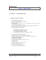
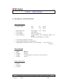
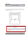
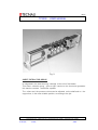
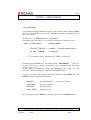
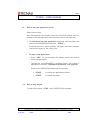
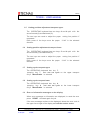
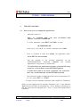
1/41 TC2000 - USER MANUAL HIGH PERFORMANCE DUAL-WEB CUTTER SERIES TC 2000 Corso Vercelli 139 – 10015 Ivrea (To) – Phone # (39) 0125 / 615431 – Fax # (39) 0125 / 615344 Rev.04-May’02 (C2XX00) TC2000 2/41 TC2000 - USER MANUAL USER GUIDE Table of contents Page 1. Product description 3 2. Product characteristics 4 3. Technical specification 5 4. Cutter models 7 5. Transport and installations 9 6. Main groups description 11 7. Replacement of the cartridge 16 8. Operating instructions 17 9. Interface Signals 34 10. Maintenance 37 11. Suggested spare part list 41 Corso Vercelli 139 – 10015 Ivrea (To) – Phone # (39) 0125 / 615431 – Fax # (39) 0125 / 615344 Rev.04-May’02 (C2XX00) TC2000 3/41 TC2000 - USER MANUAL 1) PRODUCT DESCRIPTION The TECNAU high performance cutter is formed of modular groups, assembled with rigid metallic structures and high precision components that guarantee long life and easy maintenance. The TECNAU cutters are generally integrated in complex systems and lines like laser printers, bookmaking systems, high performance inserters , finishing on demand applications because of their high reliability and durability. The main structure is built in stabilised aluminium and steel with cross bar of stabilised cast iron. The cross blade group and the side trimming circular knives group are designed and built as removable and interchangeable cartridges (patented) that can be easily replaced by the operator. Two different models of cross blade cartridges, the Oscillating Blade Cartridge (TC 2010) and the Vertical Blade Cartridge (TC 2020) can be used with the Tecnau cutter, depending on the Customer application. The two cartridges, interchangeable, are changed in few minutes and the customer can use one of the two according with his needs. * The Oscillating Blade Cartridges achieves highest durability cutting speed in applications not requiring strip removal. and * The Vertical Blade Cartridges is able to remove strips, of the same blade thickness, at a single stroke. The TECNAU cutter has a vertical lifting device that allows to adjust the height of the paper level in order to easily connect the cutter to other equipment. The TECNAU cutter has one or two feeding channel and is able to cut and trim continuous stationery of various format and material with single and with dual webs. Corso Vercelli 139 – 10015 Ivrea (To) – Phone # (39) 0125 / 615431 – Fax # (39) 0125 / 615344 Rev.04-May’02 (C2XX00) TC2000 4/41 TC2000 - USER MANUAL 2) PRODUCT CHARACTERISTICS TECNAU CUTTER TC 2000 Microprocessor controlled Up to two independent feeding channels Single or dual web entry Paper transport and blade driven by brushless motors (no wear and maintenance) Up to 99 cutting programs memory Parallel and serial interface for on-line connection with external devices Minimised maintenance cost and time Modular design and construction * * * * Oscillating Blade Cartridge (TC 2010) Vertical Blade Cartridge (TC 2020) Side Trimming Cartridge (TC 2002) Side trimming and central cut cartridge (TC 2003) Base on wheels with blocking device Height adjustment paper level device (TC2005) Display and keyboard for programming , information and services Automatic paper loading Automatic stop and paper end Programmable cut length Cutting speed and paper acceleration control Plexiglas cover Service counter Optical mark reader (OMR) (Optional) Bar code reader (Optional) 1/6” and 1/8” paper increments Maximum pin feeders width 480 mm Corso Vercelli 139 – 10015 Ivrea (To) – Phone # (39) 0125 / 615431 – Fax # (39) 0125 / 615344 Rev.04-May’02 (C2XX00) TC2000 5/41 TC2000 - USER MANUAL 3) TECHNICAL SPECIFICATION Paper Specification Paper weight: Min Max Max weight 150 gr/mq Max 480 mm Min 2” 5/6 max 24” Programmable with Oscillating Blade (TC 2010) 1/6” with vertical Blade ( TC 2020 ) Multicopy forms: Form width: Form height: Strip cut facility: 50 150 Trimming up to 25 mm per side Paper speed adjustment : 99 positions Height paper level from the floor (TC 2005 option): gr/mq gr/mq from 970 mm to 1210 mm Size and weight Width: Dept: Height: Height: Weight: 800 mm 650 mm 1100 m TC 2005 option: min 1055 mm, max 1295 mm 180 kg Power requirement 230 V 50/60 Hz 2.0 KVA Corso Vercelli 139 – 10015 Ivrea (To) – Phone # (39) 0125 / 615431 – Fax # (39) 0125 / 615344 Rev.04-May’02 (C2XX00) TC2000 6/41 TC2000 - USER MANUAL Cartridge Oscillating Blade Cartridge Vertical Blade Cartridge Side trimming cartridge Side trimming and central cut cartridge (TC 2010) (TC 2020) (TC 2002) (TC 2003) Cutting (cuts per hour) Cartridge TC 2010 TC 2010 TC 2020 TC 2020 Cut Selected Strip Cut Dual Stroke Single Cut Single Cut Strip Cut Single Stroke Form Height 4” 17.000 30.000 30.000 30.000 Form Height 8” 14.000 22.000 22.000 22.000 Form Height 12” 12.000 18.000 18.000 18.000 Corso Vercelli 139 – 10015 Ivrea (To) – Phone # (39) 0125 / 615431 – Fax # (39) 0125 / 615344 Rev.04-May’02 (C2XX00) TC2000 7/41 TC2000 - USER MANUAL 4) CUTTER MODELS TC 2000 MODELS Oscillating Blade Cartridge 2012 2013 * * Vertical Blade Cartridge Side Trimming Cartridge Side Trimming and Central Cut Cartridge * 2022 2023 * * * * * MODELS DESCRIPTION TC 2000 LINE High performance, dual channel, standalone cutter with oscillating or vertical blade cartridge and with side trimming cartridge, parallel and serial interface ,display for programming and operating purpose. Mod. TC 2012 TC 2000 with oscillating blade cartridge and side trimming cartridge 20.000 cuts per hour with 12” form height. Mod. TC 2013 TC 2000 with oscillating blade cartridge , side trimming and central cut cartridge, 20.000 cuts per hour with 12” form height. Mod. TC 2022 TC 2000 with vertical blade cartridge and side trimming cartridge, 18.000 cuts per hour with 12” form height, strip cut 1/6” single stroke. Mod. TC 2023 TC 2000 with vertical blade cartridge, side trimming and central cut cartridge, 18.000 cuts per hour with 12” form height strip cut 1/6”, single stroke. Corso Vercelli 139 – 10015 Ivrea (To) – Phone # (39) 0125 / 615431 – Fax # (39) 0125 / 615344 Rev.04-May’02 (C2XX00) TC2000 8/41 TC2000 - USER MANUAL CUTTER OPTIONS TC 2004 Merger interface for TC 2000 models. The option enable the connection of the cutter to the merger device. TC 2005 Cutter height (floor paper level) adjustment device for TC 1000 and TC 2000 models. Paper level adjustment from 970 mm. to 1210 mm. TC 1006 Waste paper bin. TC 2007 Central knife group. TC 2008 Paper loop control device for connection to laser printers up to 85 mt/min. CUTTER CARTRIDGES TC 2010 Oscillating blade cartridge. TC 2020 Vertical blade cartridge. TC 2002 Side trimming cartridge. TC 2003 Side trimming and central cut cartridge. OTHER DEVICES TC 1100 Merger device with basement for connection to the TC 2000 models with TC 2004 option (merger interface). Corso Vercelli 139 – 10015 Ivrea (To) – Phone # (39) 0125 / 615431 – Fax # (39) 0125 / 615344 Rev.04-May’02 (C2XX00) TC2000 9/41 TC2000 - USER MANUAL 5) TRANSPORT AND INSTALLATION The cutter can be lifted with a lifting unit by passing it through the two bars under the structure as indicated in the figure 1. Fig. 1 Four wheels are located in the base and allow to move the cutter in the working area manually. The cutter can be fixed at the floor rotating the four screws at the corner of the base with the key. Four cylinders with anti-shocking material will be moved vertically by the screws up to fixing the cutter on the floor. See figures 2 and 3. Fig. 2 Fig. 3 Corso Vercelli 139 – 10015 Ivrea (To) – Phone # (39) 0125 / 615431 – Fax # (39) 0125 / 615344 Rev.04-May’02 (C2XX00) TC2000 10/41 TC2000 - USER MANUAL If the cutter has the option TC 2005, it is possible to adjust the height of the paper output plane from 970 mm to 1210 mm. rotating the screw located at the centre of the base with the key. See figure 4. Fig.4 ATTENTION!!! In order to minimize the static electricity is necessary to check and, if is not, to ground and connect to the earth, all the devices, before and after the cutter, where the paper is flowing or touching. Corso Vercelli 139 – 10015 Ivrea (To) – Phone # (39) 0125 / 615431 – Fax # (39) 0125 / 615344 Rev.04-May’02 (C2XX00) TC2000 11/41 TC2000 - USER MANUAL 6) MAIN GROUPS DESCRIPTION PAPER FEEDING GROUP The brushless motor drives the splinted shaft through the tooth belt and the pulley fixed at the left side of the shaft (fig.5). The shaft moves the two tractors, one on the left and one on the right side that transport the paper. The position of the two tractors along the shaft can be adjusted according with the paper width. On the left tractor there is one optical fibre sensor to fix the correct position of the cutting line when the paper is loaded. Fig. 5 Corso Vercelli 139 – 10015 Ivrea (To) – Phone # (39) 0125 / 615431 – Fax # (39) 0125 / 615344 Rev.04-May’02 (C2XX00) TC2000 12/41 TC2000 - USER MANUAL OSCILLATING BLADE CARTRIDGE The oscillating blade cartridge (Fig.6), with the reduced inertia of its mechanism, allows to reach the highest speed and productivity (cuts/hour) in the jobs where the strip cut is not required. Because of the blade group rigidity, the life of the oscillating blade is longer than the vertical one, up to ten million cuts. The pinion moves the shaft (1) that transmits the motion to the two eccentrics, the side rods (2) and the pins (3) that move with oscillating motion the bar (4). The blade that has the shape of cylindrical segment is fixed at the oscillating holding bar. Fig. 6 Corso Vercelli 139 – 10015 Ivrea (To) – Phone # (39) 0125 / 615431 – Fax # (39) 0125 / 615344 Rev.04-May’02 (C2XX00) TC2000 13/41 TC2000 - USER MANUAL VERTICAL BLADE CARTRIDGE The vertical blade cartridge (Fig. 7) is preferably used in the applications where the 1/6” strip cut is required. The vertical blade mechanism takes the motion from the cutter through the pinion (1) assembled on the main shaft of the rods. The shaft (2) transmits the motion to the two eccentrics (3) mounted at the two edge of the shaft. The two eccentrics (3) drive through roller bearings, the two rods with two steel plates (4) that move vertically the blade (5) fixed to their edge. This system avoids pins, bearing and other connecting devices minimising any mechanical play. The vertical blade moves between two lubricated adjustable guide blocks (6). To obtain the strip requested there are two counter – blades (7) assembled with two cast iron bars pulled against the central vertical blade by two springs. Fig. 7 Corso Vercelli 139 – 10015 Ivrea (To) – Phone # (39) 0125 / 615431 – Fax # (39) 0125 / 615344 Rev.04-May’02 (C2XX00) TC2000 14/41 TC2000 - USER MANUAL SIDE TRIMMING CARTRIDGE (TC 2002-TC 2003) The cartridge TC 2002 (fig.9) has two couples of circular knives, Fig.8 (A), for trimming one the left and one the right side of the paper module. The lower knife is driven by the shaft (F) controlled by a bruhsless motor through one tooth belt and a couple of pulleys (G is one). The upper knife is driven by the couple of cog- wheels (E) The lower knife is slightly pressed against the upper knife by two dished plate springs. The pressure is adjusted with the flange (C). The paper strip trimmed are ejected through the two plates (B). The cartridge TC 2003 has three couples of circular knives, two for trimming the left and right side and one for cutting the continuos module in the middle. Fig. 8 Corso Vercelli 139 – 10015 Ivrea (To) – Phone # (39) 0125 / 615431 – Fax # (39) 0125 / 615344 Rev.04-May’02 (C2XX00) TC2000 15/41 TC2000 - USER MANUAL Fig. 9 SHEET EXTRACTOR GROUP Is integrated in the side trimming cartridge at the exit of the blades. This sheet extractor group gives a light traction to the sheet and guarantee this traction constant at different speeds. The rollers and the pressure rollers can be adjusted on the shaft and on the support bar, in the most suitable position, according to the job. Corso Vercelli 139 – 10015 Ivrea (To) – Phone # (39) 0125 / 615431 – Fax # (39) 0125 / 615344 Rev.04-May’02 (C2XX00) TC2000 16/41 TC2000 - USER MANUAL 7) REPLACEMENT OF THE CARTRIDGES A. To replace the Oscillating Blade Cartridge (TC 2010) or the Vertical Blade Cartridge (TC 2020): 1) Remove first the “Side trimming cartridge” (see below) 2) Unscrew the two screws on the top of the cartridge. 3) Screw into the two holes two handles supplied with the cutter. 4) Lift moving forward carefully the cartridge 5) Replace the cartridge with another one using the same handles. 6) Screw off the two handles. 7) Screw down the two locking screws on the top of the cartridge. 8) Replace then the “Side trimming cartridge” and close the cover. B. To replace the Side trimming cartridge (TC 2002 or TC 2003): 1) Open the right side cover, removing the two screws. 2) Remove the belt between the motor and the cartridge placed on the right side of the cutter. 3) Unscrew the two screws carefully. in front of the cartridge and remove it 4) Replace the cartridge with the new one. 5) Screw down the two screws to lock the new cartridge. 6) Put in the same position as before the belt and the side cover. Corso Vercelli 139 – 10015 Ivrea (To) – Phone # (39) 0125 / 615431 – Fax # (39) 0125 / 615344 Rev.04-May’02 (C2XX00) TC2000 17/41 TC2000 - USER MANUAL 8) OPERATING INSTRUCTIONS 1) GENERAL INFORMATION 1.1. How to load the paper * Open the plexiglas cover * Open the tractors’ covers * Pass the paper under the brush, turn out the two knobs of the tractors adjusting their position and centring the paper holes on the sprockets, then lock the knobs. (Avoid having the paper too tight / loose between the tractors). * Close the tractors’ covers. Same operation for the upper web. * To position the circular knives, turn out the knobs put on each knife, and moving the knife groups to right or left, adjust them to have the knives in the position of the wanted trimming. * Close the plexiglas cover. * Turn-on the cutter through the main switch. * The display shows information of the software installed. Corso Vercelli 139 – 10015 Ivrea (To) – Phone # (39) 0125 / 615431 – Fax # (39) 0125 / 615344 Rev.04-May’02 (C2XX00) TC2000 18/41 TC2000 - USER MANUAL 1.2. The Keyboard The keyboard is placed on the left side of the cutter and is divided into four parts: * The EDITING keyboard on the left side: six keys, four blue to select and/or edit the applications, two white for service. * The OPERATING keyboard on the center: four keys that allow to start and stop the selected application * The ALPHANUMERIC keyboard on the right side: 12 keys that allows, in connection with the EDITING keyboard, to set up new applications and to modify the existing ones and to settle the cutting line and the cutter speed. * The alphanumerical DISPLAY for text messages Fig. 10 Corso Vercelli 139 – 10015 Ivrea (To) – Phone # (39) 0125 / 615431 – Fax # (39) 0125 / 615344 Rev.04-May’02 (C2XX00) TC2000 19/41 TC2000 - USER MANUAL 1.2.1 The Display It is possible to display different windows, with different data, pressing DSPL key. For every windows, the actual Application number is available on the left of the first line. At power on, the STATUS window is displayed. According with the status of the cutter, the displayed information are: Ap.01 < Cutter mode > < Merger mode > < To run 1st LW*/UP* > < ready > < In run 1st LW/UP > < Printer loop/no loop > < no ready > * 1st cut upper or lower selectable by SEL on keyboard. Pressing once the DSPL key, the display show: PASSWORD , “Total cuts” counter, ”Partial cuts” counter, (upper line); name and date of the “Firmware version” (lower line). In this page is possible to enter the Passwords (see page 22, THE APPLICATIONS and page 29, MACHINE PARAMETERS). If you do not enter the operator password, pressing again DSPL key, the SPEED window is displayed.(lower line) Spd= 077 presetted speed or actual speed value mt/m= 080 meter per minute ft/m= 260 feet per minute Pg/h= 17600 pages per hour On the next pressing of DSPL key changes again to the STATUS window. . Corso Vercelli 139 – 10015 Ivrea (To) – Phone # (39) 0125 / 615431 – Fax # (39) 0125 / 615344 Rev.04-May’02 (C2XX00) TC2000 20/41 TC2000 - USER MANUAL 1.3. How to start the application or job Switch on the cutter. After few seconds, the display shows the STATUS window with the number of the last application executed on the left of the upper line. To start again the last application executed, load the paper and press on the OPERATING keyboard START : the blade moves to phase position, the upper and lower transport load the two webs to the cutting line To start a new application: * Press EDIT for two seconds: the display shows the number of the last application. * Through the ALPHANUMERIC keyboard, select the number of application to execute. ( password requested – see page 22 ) * Press on the OPERATING keyboard, in sequence: 1.4 START to confirm the application number START to reload the paper How to stop the job To stop the job press STOP on the OPERATING keyboard Corso Vercelli 139 – 10015 Ivrea (To) – Phone # (39) 0125 / 615431 – Fax # (39) 0125 / 615344 Rev.04-May’02 (C2XX00) TC2000 21/41 TC2000 - USER MANUAL 1.5 Cutting position adjustment transport upper The OPERATING keyboard has two keys, 8 and 9 split with the arrow forward (8) and backward (9). The two keys are used to adjust the paper cutting line position if requested. Each press of the keys move the paper 1/144” in the selected direction. 1.6 Cutting position adjustment transport lower The OPERATING keyboard has two keys, 5 and 6 split with the arrow forward (5) and backward (6). The two keys are used to adjust the paper cutting line position if requested. Each press of the keys move the paper 1/144” in the selected direction. 1.7 Cutting cycle transport upper The OPERATING keyboard has key 7. pressing key 7 start one cut cycle on the upper transport only if ManuEnable is selected 1.8 Cutting cycle transport lower The OPERATING keyboard has key 4. pressing key 4 start one cut cycle on the lower transport only if ManuEnable is selected 1.9 Error or information messages on the display When error messages or information are displayed, to reset the error press RESET and start again the job. If the error message continue to be displayed, detect the error code in the upper line at right of the display and call the service centre. Corso Vercelli 139 – 10015 Ivrea (To) – Phone # (39) 0125 / 615431 – Fax # (39) 0125 / 615344 Rev.04-May’02 (C2XX00) TC2000 22/41 TC2000 - USER MANUAL 2. THE APPL ICATIONS 2.1 How to set up or to change the applications. * Switch the cutter on New or modified data can specific Operator PASSWORD only be entered with To enter password press EDIT, then DSPL to show: ## PASSWORD ## press keys 1, 2, 3, 4, 5 on numeric keyboard and DSPL * Now is possible to enter and modify the application data. * Press EDIT for two seconds * Set the number of the required application ALPHANUMERICAL keyboard, examine the applications using arrow up / arrow down. * To switch from one parameter to another press the blue key arrow up or arrow down on the EDITING keyboard * To enter more data in the same parameter line press the blue key arrow backward on the EDITING keyboard * The maximum number of application that can be memorised is 99 To exit press EDIT or START on the existing * To logout from the operator Password, enter “00000” as Password. While you are logged with the operator Password, the “=” sign between “Spd” and the set value of the speed (e.g. “45”) is flashing, reminding you that the speed can be changed with “-“ and “+” keys of the alphanumeric keyboard. Corso Vercelli 139 – 10015 Ivrea (To) – Phone # (39) 0125 / 615431 – Fax # (39) 0125 / 615344 Rev.04-May’02 (C2XX00) TC2000 23/41 TC2000 - USER MANUAL 1° Parameter Application # : Pressing the key arrow up the display visualise “APPLICATION” and it’s possible to enter the number of the application from 1 to 99. 7 8 9 4 5 6 1 2 3 0 - + 2° Parameter Paper speed: This parameter sets the paper feeding speed. The numerical value is between 5 for the minimum speed and 99 for the maximum speed. Sequence : select the parameter Introduce the speed value ( two digits ) Corso Vercelli 139 – 10015 Ivrea (To) – Phone # (39) 0125 / 615431 – Fax # (39) 0125 / 615344 Rev.04-May’02 (C2XX00) TC2000 24/41 TC2000 - USER MANUAL 3° Parameter Merger mode < 0=no 1=up 2=lw 3=both > : Select “ 0 “ to run paper from fan-fold Select “ 1 “ to run paper from merger to upper web only Select “ 2 “ to run paper from merger to lower web only Select “ 3 “ to run paper from merger to upper and lower web in alternate mode 4° Parameter Cut mode < 0=presel. 1=sel. 2=altern. > : Select “ 0 “ to run preselected mode defined in parameter 6° Select “ 1 “ to run in selective mode by External Start UP/LW signals Select “ 2 “ to run in alternate sequence mode Upper and Lower web 5° Parameter Foils qty. < cut mode 2 > : To define the number of foils per group Select “ 00000 “ to run continuously Corso Vercelli 139 – 10015 Ivrea (To) – Phone # (39) 0125 / 615431 – Fax # (39) 0125 / 615344 Rev.04-May’02 (C2XX00) TC2000 25/41 TC2000 - USER MANUAL 6° Parameter UP.LW < mode 0 > : xx.xx.xx.xx.xx.xx.xx.xx To define the sequence and the number of foils cuts for each transport for the composition of one set (group). For each group the number can change from 0 to 98 Sequence: select the parameter Introduce the value 7° Parameter UP cut length 01 (“+/96”) : To define the length of the sheet to be cut from the upper transport Inches + /96 Sequence: select the parameter Introduce the value 8° Parameter UP cut length 02 (“+/96”) : To define the length of the second cut or, of the strip to be cut from the upper transport Sequence: select the parameter Introduce the value Corso Vercelli 139 – 10015 Ivrea (To) – Phone # (39) 0125 / 615431 – Fax # (39) 0125 / 615344 Rev.04-May’02 (C2XX00) TC2000 26/41 TC2000 - USER MANUAL 9° Parameter LW cut length 01 (“+/96”) : To define the length of the sheet to be cut from the lower transport Inches + /96 Sequence: select the parameter Introduce the value 10° Parameter LW cut length 02 (“+/96”) : To define the length of the second cut or, of the strip to be cut from the lower transport . Sequence: select the parameter Introduce the value 11° Parameter LW cut length 16 (“+/96”) : To define the length of the sixteenth cut from the lower transport . Sequence: select the parameter Introduce the value Corso Vercelli 139 – 10015 Ivrea (To) – Phone # (39) 0125 / 615431 – Fax # (39) 0125 / 615344 Rev.04-May’02 (C2XX00) TC2000 27/41 TC2000 - USER MANUAL 12° Parameter Printer loop <merger mode 3 > 1=yes : Only in <merger mode 3 > condition, when the paper is supplied from a digital printer Select “ 0 “ to run paper from fan-fold or from unwinder Select “ 1 “ to run paper from digital printer 13° Parameter Blade version < 0=osc. 1=V1 2=V2 > : Select “ 0 “ when use “ Oscillating blade system” TC 2010 Select “ 1” when use “ Vertical blade system” TC 2050 Select “ 2” when use “ Vertical blade system” TC 2020 Corso Vercelli 139 – 10015 Ivrea (To) – Phone # (39) 0125 / 615431 – Fax # (39) 0125 / 615344 Rev.04-May’02 (C2XX00) TC2000 28/41 TC2000 - USER MANUAL MACHINE PARAMETERS Corso Vercelli 139 – 10015 Ivrea (To) – Phone # (39) 0125 / 615431 – Fax # (39) 0125 / 615344 Rev.04-May’02 (C2XX00) TC2000 29/41 TC2000 - USER MANUAL ATTENTION!!! This Password allows the access to the RAM of the CPU. Must be managed by specialised personnel only. Switch the cutter on, press DSPL, the display shows: ## PASSWORD ## Press 5 (five) times the key 7 and 3 times DSPL Press the keys “arrow up” and “arrow dw” to select each parameter. Corso Vercelli 139 – 10015 Ivrea (To) – Phone # (39) 0125 / 615431 – Fax # (39) 0125 / 615344 Rev.04-May’02 (C2XX00) TC2000 30/41 TC2000 - USER MANUAL MACHINE PARAMETERS 1. Paper load UP, 1”=192 Default data 01250 The parameter defines the distance between the photo sensor of paper presence on upper right tractor and the Cut Line. The data is expressed in 1/192 of inch. 2. Paper load LW, 1”=192 Default data 01305 The parameter defines the distance between the photo sensor of paper presence on lower left tractor and the Cut Line. The data is expressed in 1/192 of inch.. 3. Merger paper jam (1=yes) Default data 00000 Select “ 0 “ to disable paper jam device on merger Select “ 1 “ to enable paper jam device on merger 4. Cutter jam, (0=no 1=up 2=lw 3=both) Default data 00000 Select “ 0 “ to disable paper jam device on up and lw transport Select “ 1 “ to enable paper jam device on up transport only Select “ 2 “ to disable paper jam device on lw transport only Select “ 3 “ to enable paper jam device on up and lw transport Corso Vercelli 139 – 10015 Ivrea (To) – Phone # (39) 0125 / 615431 – Fax # (39) 0125 / 615344 Rev.04-May’02 (C2XX00) TC2000 31/41 TC2000 - USER MANUAL 5. Pg. Counter stacker reset Default data 00020 This parameter defines the number of pages cut after witch the stacker table check position (upper reset). 6. OMR phot. UP 1”=192 Default data 02400 This parameter defines for upper transport, the distance between the “OMR reading device” and the paper cutting line. The data is in 1/192 of inch. 7. OMR phot. LW 1”=192 Default data 02400 This parameter defines for lower transport, the distance between the “OMR reading device” and the paper cutting line. The data is in 1/192 of inch. 8. OMR window 1”=192 Default data 00020 This parameter is the window size within which the “OMR reading device” can read and recognize the information printed. The data is in 1/192 of inch. 9. Auto. OMR Set, 0Yes 1No 2NoOMR Default data 00002 Select “ 0 “ to enable “automatic centring mark position” device. Select “ 1 “ to disable “automatic centring mark position” device. Select “ 2 “ to disable all OMR reading device. Corso Vercelli 139 – 10015 Ivrea (To) – Phone # (39) 0125 / 615431 – Fax # (39) 0125 / 615344 Rev.04-May’02 (C2XX00) TC2000 32/41 TC2000 - USER MANUAL 10. Language 0=It 1=Uk 2=Dc Default data 00001 This parameter allows the language selection. 11. Delay between groups 1=5ms. Default data 00020 12. Max strip dimension 1”=192. Default data 00096 This value defines the maximum length within which the paper cut is calculated as strip. 13. Keyboard position, 1=right Default data 00000 This parameter is normally set to 0 Must be set to 1 if the Keyboard (with Display) is mounted on the right side of the Cutter. Doing this, some specific keys like “Cutting position adjustment”, and some display indications, assume the correct direction. 14. Without controls ? * 1=yes Default data 00000 Setting the value to 1 the “paper presence” and the “cover open” controls are disabled. Corso Vercelli 139 – 10015 Ivrea (To) – Phone # (39) 0125 / 615431 – Fax # (39) 0125 / 615344 Rev.04-May’02 (C2XX00) TC2000 33/41 TC2000 - USER MANUAL 15. Reload default parameters ? (*) 1=yes Default data 00000 If this value is 0 any changing of listed parameters is valid. Enter 1 to reload the “default parameters” at next Power-on. To confirm any change of parameter value, press arrow up or arrow down, then switch off and on again the cutter. (*) NOTE: Parameter 14 and 15 that when switch off, reset itself to 0. Corso Vercelli 139 – 10015 Ivrea (To) – Phone # (39) 0125 / 615431 – Fax # (39) 0125 / 615344 Rev.04-May’02 (C2XX00) TC2000 34/41 TC2000 - USER MANUAL 9) INTERFACE SIGNALS Input/Output Signals for external devices connection are available on two external connectors “D” type, 25 way Female, named U6 A and U6 B. INPUT SIGNALS: All the inputs are active low and have an internal pull-up of 10 Kohm to +24V. 1) External Group Start U6A/B-25 When the 4° Parameter “Cut Mode” is set to “0” (presel), a pulse on this input starts the sequence on upper and lower web defined by the 6° Parameter “UP.LW<mode 0>”. 2) External Start UP U6A/B-13 a) When Cut Mode parameter is set to “1” (sel), a pulse on this input starts the cutting activity on the upper web. If the External Stop signal is active, a pulse on this input starts a single sheet cut on the upper web. b) When Cut Mode parameter is set to “2” (altern), a pulse on this input starts the activity of the cutter. If the External Stop signal is active, a pulse on this input starts a single sheet cut. 3) External Start LW U6A/B-11 a) When Cut Mode parameter is set to “1” (sel), a pulse on this input starts the cutting activity on the lower web. If the External Stop signal is active, a pulse on this input starts a single sheet cut on the lower web. b) When Cut Mode parameter is set to “2” (altern), a pulse on this input starts the activity of the cutter. If the External Stop signal is active, a pulse on this input starts a single sheet cut. Corso Vercelli 139 – 10015 Ivrea (To) – Phone # (39) 0125 / 615431 – Fax # (39) 0125 / 615344 Rev.04-May’02 (C2XX00) TC2000 35/41 TC2000 - USER MANUAL 4) External Stop U6A/B-10 A pulse on this input stops the cutting activity of the Cutter. If this signal is tied active, a pulse on External Start LW or External Start UP starts a single sheet cut on the appropriate web. 5) External S/S Common (Return) U6A/B-12 Common Signal (0V of input circuit) for External Start and Stop Signals. OUTPUT SIGNALS: All the Outputs are electrically insulated contacts. Cutter Ready Common U6A/B-4 Common contact of Cutter Ready relay. Cutter Ready NO U6A/B-5 Normally Open contact of Cutter Ready relay. This contact is closed when: a) the Cutter is working b) the Cutter is ready to work waiting for START or an External Start. c) the Cutter is waiting for Paper Loop presence (if enabled). Cutter Ready NC U6A/B-6 Normally Closed contact of Cutter Ready relay. This contact is open when: a) the Cutter is working b) the Cutter is ready to work waiting for START or an External Start. c) the Cutter is waiting for Printer Loop presence (if enabled). Corso Vercelli 139 – 10015 Ivrea (To) – Phone # (39) 0125 / 615431 – Fax # (39) 0125 / 615344 Rev.04-May’02 (C2XX00) TC2000 36/41 TC2000 - USER MANUAL Cutter Powered Common U6A/B-7 Common contact of Cutter Powered relay. Cutter Powered NO U6A/B-8 Normally Open contact of Cutter Powered relay. This contact is closed when the machine is switched ON. Cutter Powered NC U6A/B-9 Normally Closed contact of Cutter Powered relay. This contact is open when the machine is switched ON. End Of Group Common U6A/B-15 Common contact of End Of Group relay. End Of Group NO U6A/B-16 Normally Open contact of End Of Group relay. This contact is closed for the time set in the Machine Parameter “Delay between groups” at the end of each Group of sheets. Corso Vercelli 139 – 10015 Ivrea (To) – Phone # (39) 0125 / 615431 – Fax # (39) 0125 / 615344 Rev.04-May’02 (C2XX00) TC2000 37/41 TC2000 - USER MANUAL 10) MAINTENANCE The main cutter parts are protected by gaskets to avoid the paper dust to enter into the rotating devices and to block them. It’s important to clean the cutter, using vacuum cleaner, when the paper dust starts cumulating. It’s suggested to clean the cutter every day before starting working. The most important parts are lubricated with grease (bearing etc.) for life and sealed. Frequency: daily Corso Vercelli 139 – 10015 Ivrea (To) – Phone # (39) 0125 / 615431 – Fax # (39) 0125 / 615344 Rev.04-May’02 (C2XX00) TC2000 38/41 TC2000 - USER MANUAL The trimming circular knives are lubricated with oil through a wick that pushes against the thread of the lower knives: this transmits the lubrication to the upper knives by rubbing. It’s recommended to introduce oil in the lateral hole, daily, as indicated in the figure. Frequency: daily The lubrication increase the life of the knife and keep the cut quality at the original level. Corso Vercelli 139 – 10015 Ivrea (To) – Phone # (39) 0125 / 615431 – Fax # (39) 0125 / 615344 Rev.04-May’02 (C2XX00) TC2000 39/41 TC2000 - USER MANUAL Lubricate tractor drives monthly. Prevent tractor jamming. During normal working hours, the operator of the units should follows the listen procedures as a preventive action against dust build up and to achieve maximum performance and production reliability of machines. Frequency: monthly Check and oil all moving parts with a very light coat, oil wicks in slitting blocks. Corso Vercelli 139 – 10015 Ivrea (To) – Phone # (39) 0125 / 615431 – Fax # (39) 0125 / 615344 Rev.04-May’02 (C2XX00) TC2000 40/41 TC2000 - USER MANUAL Oil the cross oscillating blades at the extremity (from the holes on the upper side of cartridge). Frequency: weekly Corso Vercelli 139 – 10015 Ivrea (To) – Phone # (39) 0125 / 615431 – Fax # (39) 0125 / 615344 Rev.04-May’02 (C2XX00) TC2000 41/41 TC2000 - USER MANUAL Suggested spare part list TECNAU PART NUMBER DESCRIPTION TC 1010 OSCILLATING BLADE CARTRIDGE TC 2002 SIDE TRIMMING CARTRIDGE COMM0144 BELT - EJECTOR COMM0146 BELT - BLADE DRIVE COMM9359 BELT - TRACTOR DRIVE COMM0400 BLADE - MOTOR COMM0401 TRACTOR --MOTOR COMM0403 PAPER SENSOR AMPLIFIER COMM0404 OPTICAL FIBER COMM0405 FAN COMM0407 CAPACITOR COMM0408 RECTIFIER COMM0409 MAIN TRANSFORMER R/COMM0410 KEYBOARD WITH DISPLAY COMM0411 BLADE MOTOR DRIVER COMM0412 TRANSPORT MOTOR DRIVER COMM0415 ELECTRONIC BOARD COMM0416 ELECTR. BOARD TRANSFORMER CT18.03/C03 CENTRAL OR SIDE KNIFE CT18.03/C39 LOWER EJECTOR WHEEL T200HP 90 UPPER EJECTOR GROUP Corso Vercelli 139 – 10015 Ivrea (To) – Phone # (39) 0125 / 615431 – Fax # (39) 0125 / 615344 Rev.04-May’02 (C2XX00) TC2000