1
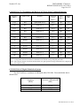
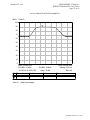
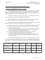
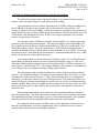
Nemko-CCL, Inc. 1940 West Alexander Street Salt Lake City, UT 84119 801-972-6146 Test Report Certification Test Of: MICRO-RM2.4-LB IC: 12298A-RM2 Test Specifications: RSS-Gen Issue 3 (December 2010) RSS-210 Issue 8 (December 2010) Test Report Serial No.: 270649-4.1 Applicant: MicroRidge Systems, Inc. 56888 Enterprise Drive Sunriver. OR 97707 U.S.A Dates of Test: October 1 – 2, 2014 Report Issue Date: October 27, 2014 Accredited Testing Laboratory By: NVLAP Lab Code 100272-0 Nemko-CCL, Inc. TEST REPORT: 270649-4.1 REPORT ISSUE DATE: 10/27/2014 Page 2 of 45 CERTIFICATION OF ENGINEERING REPORT This report has been prepared by Nemko-CCL, Inc. to document compliance of the device described below with the requirements of RSS-Gen Issue 3 (December 2010) and RSS210 Issue 8 (December 2010). This report may be reproduced in full. Partial reproduction may only be made with the written consent of the laboratory. The results in this report apply only to the sample tested. - Applicant: MicroRidge Systems, Inc. - Manufacturer: MicroRidge Systems, Inc. - Brand Name: MicroRidge - Model Number: MICRO-RM2.4-LB - IC: 12298A-RM2 On this 27th day October 2014, I, individually and for Nemko-CCL, Inc., certify that the statements made in this engineering report are true, complete, and correct to the best of my knowledge, and are made in good faith. Although NVLAP has recognized that the Nemko-CCL, Inc. EMC testing facilities are in good standing, this report must not be used to claim product certification, approval, or endorsement by NVLAP, NIST, or any agency of the federal government. Nemko-CCL, Inc. Tested by: Norman P. Hansen Test Technician Reviewed by: Thomas C. Jackson Certification Manager TRF-RSS210 Issue 4 Oct. 2014 Nemko-CCL, Inc. TEST REPORT: 270649-4.1 REPORT ISSUE DATE: 10/27/2014 Page 3 of 45 TABLE OF CONTENTS PAGE SECTION 1.0 CLIENT INFORMATION .................................................................................4 SECTION 2.0 EQUIPMENT UNDER TEST (EUT)..................................................................5 SECTION 3.0 TEST SPECIFICATION, METHODS & PROCEDURES .............................7 SECTION 4.0 OPERATION OF EUT DURING TESTING..................................................12 SECTION 5.0 SUMMARY OF TEST RESULTS ...................................................................13 SECTION 6.0 802.11b/g/n TRANSCEIVER – MEASUREMENTS AND RESULTS..........14 APPENDIX 1 TEST PROCEDURES AND TEST EQUIPMENT .........................................30 APPENDIX 2 PHOTOGRAPHS ................................................................................................35 TRF-RSS210 Issue 4 Oct. 2014 Nemko-CCL, Inc. TEST REPORT: 270649-4.1 REPORT ISSUE DATE: 10/27/2014 Page 4 of 45 SECTION 1.0 CLIENT INFORMATION 1.1 Applicant: Company Name: MicroRidge Systems, Inc. 56888 Enterprise Drive Sunriver, OR 97707 U.S.A. Contact Name: Title: John Schuldt President 1.2 Manufacturer: Company Name: MicroRidge Systems, Inc. 56888 Enterprise Drive Sunriver, OR 97707 U.S.A. Contact Name: Title: John Schuldt President TRF-RSS210 Issue 4 Oct. 2014 Nemko-CCL, Inc. TEST REPORT: 270649-4.1 REPORT ISSUE DATE: 10/27/2014 Page 5 of 45 SECTION 2.0 EQUIPMENT UNDER TEST (EUT) 2.1 Identification of EUT: Brand Name: Model Number: Serial Number: Dimensions: MicroRidge MICRO-RM2.4-LB None 2.1 cm x 1.2 cm 2.2 Description of EUT: The Micro-RM2.4-LB is a compact and low-power 2.4 GHz wireless module designed for industrial and consumer applications. The wireless module is built around an Atmel ATmega2564RFR2 AVR microcontroller that has an integrated radio transceiver. The wireless module also contains a chip antenna, crystals and de-coupling capacitors. This wireless module is designed to be integrated into products that require low-power short range wireless connectivity. The Micro-RM2.4-LB is an 802.15.4 compliant transceiver module. Testing was performed using a host PCB to provide the necessary connections for exercising the EUT. The host PCB received power from a computer USB port. The MICRO-RM2.4-LB transceivers use 16 channels in the 2400 to 2483.5 MHz frequency range. See the table of frequencies below. Channel 11 12 13 14 Frequency Frequency Channel (MHz) (MHz) 2405 15 2425 2410 16 2430 2415 17 2435 2420 18 2440 Channel 19 20 21 22 Frequency (MHz) 2445 2450 2455 2460 Channel 23 24 25 26 Frequency (MHz) 2465 2470 2475 2480 This report covers the circuitry of the devices subject to RSS-210. The circuitry of the device subject to ICES-003 was found to be compliant and is covered in Nemko-CCL, Inc. report 270649-2 2.3 EUT and Support Equipment: The IC numbers for all the EUT and support equipment used during the test are listed below: TRF-RSS210 Issue 4 Oct. 2014 Nemko-CCL, Inc. TEST REPORT: 270649-4.1 REPORT ISSUE DATE: 10/27/2014 Page 6 of 45 Brand Name IC Number or Compliance Model Number Description Name of Interface Ports / Interface Cables Serial Number BN: MicroRidge 12298A-RM2 Transceiver Module See Section 2.4 DoC Computer USB/USB cable None Host PCB USB/USB cable MN: MICRO-RM2.4-LB (Note 1) SN: None BN: Dell MN: Vostro SN: 2878353565 BN: MicroRidge MN: Host PCB Power/Serial communication lines/Directly soldered to host PCB (Note 2) SN: #1 BN: MicroRidge None USB Base USB/USB cable MN: USB Base SN: None Note: (1) EUT (2) Interface port connected to EUT (See Section 2.4) The support equipment listed above was not modified in order to achieve compliance with this standard. 2.4 Interface Ports on EUT: Name of Ports System Interface No. of Ports Fitted to EUT Cable Descriptions/Length 1 Soldered directly to host PCB providing power source and communication interface 2.5 Modification Incorporated/Special Accessories on EUT: There we no modifications or special accessories required to comply with the specification. TRF-RSS210 Issue 4 Oct. 2014 Nemko-CCL, Inc. TEST REPORT: 270649-4.1 REPORT ISSUE DATE: 10/27/2014 Page 7 of 45 SECTION 3.0 TEST SPECIFICATION, METHODS & PROCEDURES 3.1 Test Specification: Title: RSS-Gen Issue 3 (December 2010) RSS-210 Issue 8 (December 2010) Purpose of Test: The tests were performed to demonstrate initial compliance. 3.2 Requirements: 3.2.1 RSS-Gen 4.6.1 Occupied Bandwidth When an occupied bandwidth value is not specified in the applicable RSS, the transmitted signal bandwidth to be reported is to be its 99% emission bandwidth, as calculated or measured. The transmitter shall be operated at its maximum carrier power measured under normal test conditions. The span of the analyzer shall be set to capture all products of the modulation process, including the emission skirts. The resolution bandwidth shall be set to as close to 1% of the selected span as is possible without being below 1%. The video bandwidth shall be set to 3 times the resolution bandwidth. Video averaging is not permitted. Where practical, a sampling detector shall be used since a peak or, peak hold, may produce a wider bandwidth than actual. The trace data points are recovered and are directly summed in linear terms. The recovered amplitude data points, beginning at the lowest frequency, are placed in a running sum until 0.5% of the total is reached and that frequency recorded. The process is repeated for the highest frequency data points. This frequency is recorded. The span between the two recorded frequencies is the occupied bandwidth. 3.2.2 RSS-Gen Section 5.6 Exposure of Humans to RF Fields Category I and Category II equipment shall comply with the applicable requirements of RSS-102. 3.2.3 RSS-Gen Section 7.1.2 Transmitter Antenna A transmitter can only be sold or operated with antennas with which it was certified. A transmitter may be certified with multiple antenna types. An antenna type comprises antennas having similar in-band and out-of-band radiation patterns. Testing shall be performed using the highest-gain antenna of each combination of transmitter and antenna type for which certification TRF-RSS210 Issue 4 Oct. 2014 Nemko-CCL, Inc. TEST REPORT: 270649-4.1 REPORT ISSUE DATE: 10/27/2014 Page 8 of 45 is being sought, with the transmitter output power set at the maximum level. Any antenna of the same type and having equal or lesser gain as an antenna that had been successfully tested for certification with the transmitter, will also be considered certified with the transmitter, and may be used and marketed with the transmitter. The manufacturer shall include with the application for certification a list of acceptable antenna types to be used with the transmitter. When a measurement at the antenna connector is used to determine RF output power, the effective gain of the device's antenna shall be stated, based on measurement or on data from the antenna manufacturer. For transmitters of RF output power of 10 milliwatts or less, only the portion of the antenna gain that is in excess of 6 dBi (6 dB above isotropic gain) shall be added to the measured RF output power to demonstrate compliance with the radiated power limits specified in the applicable standard. For transmitters of output power greater than 10 milliwatts, the total antenna gain shall be added to the measured RF output power to demonstrate compliance to the specified radiated power limits. User manuals for transmitters shall display the following notice in a conspicuous location: Under Industry Canada regulations, this radio transmitter may only operate using an antenna of a type and maximum (or lesser) gain approved for the transmitter by Industry Canada. To reduce potential radio interference to other users, the antenna type and its gain should be so chosen that the equivalent isotropically radiated power (e.i.r.p.) is not more than that necessary for successful communication. The notice may be affixed to the device instead of displayed in the user manual. User manuals for transmitters equipped with detachable antennas shall also contain the following notice in a conspicuous location: This radio transmitter (identify the device by certification number, or model number if Category II) has been approved by Industry Canada to operate with the antenna types listed below with the maximum permissible gain and required antenna impedance for each antenna type indicated. Antenna types not included in this list, having a gain greater than the maximum gain indicated for that type, are strictly prohibited for use with this device. Immediately following the above notice, the manufacturer shall provide a list of all antenna types approved for use with the transmitter, indicating the maximum permissible antenna gain (in dBi) and required impedance for each. TRF-RSS210 Issue 4 Oct. 2014 Nemko-CCL, Inc. TEST REPORT: 270649-4.1 REPORT ISSUE DATE: 10/27/2014 Page 9 of 45 3.2.4 RSS-Gen Section 7.1.3 User Manual User manuals for licence-exempt LPDs shall contain the following or equivalent notice in a conspicuous location in the user manual or alternatively on the device or both. This device complies with Industry Canada licence-exempt RSS standard(s). Operation is subject to the following two conditions: (1) this device may not cause interference, and (2) this device must accept any interference, including interference that may cause undesired operation of the device. 3.2.5 RSS-Gen 7.1.4 Radio Apparatus Containing Digital Circuits (ICES-003) Radio apparatus containing digital circuitry which can function separately from the operation of a transmitter or an associated transmitter, shall comply with ICES-003. In such cases, the labeling requirements of the applicable RSS apply, rather than the labeling requirements in ICES-003. 3.2.6 RSS-Gen 7.2.2 Emissions Falling Within Restricted Frequency Bands Restricted bands, identified in Table 1, are designated primarily for safety-of-life services (distress calling and certain aeronautical bands), certain satellite downlinks, radio astronomy and some government uses. Except where otherwise indicated, the following restrictions apply: (a) Fundamental components of modulation of licence-exempt radio apparatus shall not fall within the restricted bands of Table 1; (b) Unwanted emissions falling into restricted bands of Table 1 shall comply with the limits specified in RSS-Gen; (c) Unwanted emissions not falling within restricted frequency bands shall either comply with the limits specified in the applicable RSS, or with those specified in RSS-Gen. 3.2.7 RSS-Gen Section 7.2.4 AC Power Lines Conducted Emission Limits Except when the requirements applicable to a given device state otherwise, for any radio apparatus equipped to operate from the public utility AC power supply, either directly or indirectly (such as with a battery charger), the radio frequency voltage of emissions conducted back onto the AC power lines in the frequency range of 0.15 MHz to 30 MHz shall not exceed the limits shown in the table below. The more stringent limit applies at the frequency range boundaries. The conducted emissions shall be measured with a 50 ohm/50 microhenry line impedance stabilization network (LISN). TRF-RSS210 Issue 4 Oct. 2014 Nemko-CCL, Inc. TEST REPORT: 270649-4.1 REPORT ISSUE DATE: 10/27/2014 Page 10 of 45 Table 4 – AC Power Lines Conducted Emission Limits Frequency of Emission (MHz) 0.15 – 0.5* 0.5 – 5 5 - 30 *Decreases with the logarithm of the frequency. Conducted Limit (dBµV) Quasi-peak Average * 66 to 56 56 to 46* 56 46 60 50 3.2.8 RSS-210 Annex 8 3.2.8.1 RSS-210 Section A8.2 Digital Modulation Systems These include systems employing digital modulation techniques resulting in spectral characteristics similar to direct sequence systems. The following applies to all three bands. (a) The minimum -6 dB bandwidth shall be at least 500 kHz. (b) The transmitter power spectral density conducted from the transmitter to the antenna shall not be greater than 8 dBm in any 3 kHz band during any time interval of continuous transmission. This power spectral density shall be determined in accordance with the provisions of Section A8.4(4), (i.e. the power spectral density shall be determined using the same method as is used to determine the conducted output power). 3.2.8.2 RSS-210 Section A8.4 Transmitter Output Power and e.i.r.p. Requirements For systems employing digital modulation techniques operating in the 902-928 MHz, 2400-2483.5 MHz and 5725-5850 MHz bands, the maximum peak conducted power shall not exceed 1 W. Except as provided in Section A8.5(5), the e.i.r.p. shall not exceed 4 W. As an alternative to a peak power measurement, compliance can be based on a measurement of the maximum conducted output power. The maximum conducted output power is the total transmit power delivered to all antennas and antenna elements, averaged across all symbols in the signaling alphabet when the transmitter is operating at its maximum power control level. Power must be summed across all antennas and antenna elements. The average must not include any time intervals during which the transmitter is off or transmitting at a reduced power level. If multiple modes of operation are implemented, the maximum conducted output power is the highest total transmit power occurring in any mode. TRF-RSS210 Issue 4 Oct. 2014 Nemko-CCL, Inc. TEST REPORT: 270649-4.1 REPORT ISSUE DATE: 10/27/2014 Page 11 of 45 3.2.8.3 RSS-210 Section A8.5 Out-of-band Emissions In any 100 kHz bandwidth outside the frequency band in which the spread spectrum or digitally modulated device is operating, the RF power that is produced shall be at least 20 dB below that in the 100 kHz bandwidth within the band that contains the highest level of the desired power, based on either an RF conducted or a radiated measurement, provided the transmitter demonstrates compliance with the peak conducted power limits. If the transmitter complies with the conducted power limits based on the use of root-mean-square averaging over a time interval, as permitted under section A8.4(4), the attenuation required shall be 30 dB instead of 20 dB. Attenuation below the general limits specified in RSS-Gen is not required. 3.3 Test Procedure: The testing was performed according to the procedures in RSS-Gen Issue 3 and RSS-210 Issue 8. Testing was performed at Nemko-CCL, Inc.’s Wanship open area test site #2, located at 29145 Old Lincoln Highway, Wanship, UT. This site has been registered with Industry Canada, and was accepted under Industry Canada Assigned Code 2041A-2 effective until February 14, 2015. Nemko-CCL, Inc. is accredited by National Voluntary Laboratory Accreditation Program (NVLAP); NVLAP Lab Code: 100272-0, which is effective until September 30, 2015. TRF-RSS210 Issue 4 Oct. 2014 Nemko-CCL, Inc. TEST REPORT: 270649-4.1 REPORT ISSUE DATE: 10/27/2014 Page 12 of 45 SECTION 4.0 OPERATION OF EUT DURING TESTING 4.1 Operating Environment: Power Supply: 120 VAC/60 Hz to computer/5 VDC from USB port to EUT Host PCB 4.2 Operating Modes: Each mode of operation was exercised to produce worst-case emissions and the EUT was tested on 3 orthogonal axes. The worst-case emissions were with the Micro-RM2.4-LB placed flat on the table and connected to the support equipment. The EUT was set to transmit data constantly. 4.3 EUT Exercise Software: MicroRidge ComTestSerial – FCC_Testing test software was used to exercise the EUT. TRF-RSS210 Issue 4 Oct. 2014 Nemko-CCL, Inc. TEST REPORT: 270649-4.1 REPORT ISSUE DATE: 10/27/2014 Page 13 of 45 SECTION 5.0 SUMMARY OF TEST RESULTS 5.1 RSS-Gen and RSS-210 The EUT was subjected to each of the tests shown in the summary table below. 5.1.1 Summary of Tests: Section Environmental Phenomena Frequency Range (MHz) Result RSS-Gen 4.6.1 Occupied Bandwidth 2400 – 2483.5 Reported RSS-Gen 5.6 Exposure of Humans to RF Fields 2400 – 2483.5 Complied RSS-Gen 6 Receiver Spurious Emissions Limits 30 – 7500 Exempt RSS-Gen 7.1.2 Transmitter Antenna 2400 – 2483.5 Complied RSS-Gen 7.1.3 User Manual Notice for Licence-Exempt Apparatus N/A Complied RSS-Gen 7.1.4 Radio Apparatus Containing Digital Circuits (ICES-003) 30 – 2000 Complied RSS-Gen 7.2.2 Emissions Falling Within Restricted Frequency Bands 0.009 – 24835.0 Complied RSS-Gen 7.2.4 AC Power Line Conducted Emissions Limits 0.15 – 30 Complied RSS-210 A8.2 Digital Modulation Systems – 6 dB Bandwidth and Spectral Density 2400 – 2483.5 Complied RSS-210 A8.4 Transmitter Output Power and e.i.r.p. Requirements 2400 – 2483.5 Complied RSS-210 A8.5 Out of Band Emissions 0.009 – 24835.0 Complied 5.2 Result In the configuration tested, the EUT complied with the requirements of the specification. TRF-RSS210 Issue 4 Oct. 2014 Nemko-CCL, Inc. TEST REPORT: 270649-4.1 REPORT ISSUE DATE: 10/27/2014 Page 14 of 45 SECTION 6.0 802.11b/g/n TRANSCEIVER – MEASUREMENTS AND RESULTS 6.1 General Comments: This section contains the test results and determinations only. Details of the test methods used and a list of the test equipment used during the measurements can be found in Appendix 1 of this report. 6.2 Test Results: 6.2.1 RSS-Gen 4.6.1 Occupied Bandwidth The 99% emission bandwidth was measured with the Rohde & Schwartz ESU40 using Industry Canada procedures. The 99% emission bandwidths are shown below. Frequency (MHz) Emission 99% bandwidth (MHz) 2405 2440 2480 2.21 2.23 2.25 6.2.2 RSS-Gen 5.6 Exposure of Humans to RF Fields See documents filed with this report. 6.2.3 RSS-Gen 6 Receiver Spurious Emission Standard As per Notice 2012 DRS0126, this section is not required. 6.2.4 RSS-Gen 7.1.2 Antenna Requirement The EUT uses a Johansen ANT-2450AT42B100 chip antenna soldered to the PCB and is not user replaceable. TRF-RSS210 Issue 4 Oct. 2014 Nemko-CCL, Inc. TEST REPORT: 270649-4.1 REPORT ISSUE DATE: 10/27/2014 Page 15 of 45 6.2.5 RSS-Gen 7.1.3 User Manual The User Manual contains the following statement in both English and French: Operation is subject to the following two conditions: (1) this device may not cause interference, and (2) this device must accept any interference, including interference that may cause undesired operation of the device. See documents filed with this report for a copy of the User Manual. 6.2.6 RSS-Gen 7.1.4 Digital Circuits The MICRO-RM2.4-LB was tested to the requirements of ICES-003 and found to comply. See Nemko-CCL, Inc. Test Report 270649-2. 6.2.7 RSS-Gen 7.2.2 Emissions Falling Within Restricted Frequency Bands The frequency range from the lowest frequency generated or used in the device to the tenth harmonic of the highest fundamental frequency was investigated to measure any radiated emissions in the restricted bands of RSS-Gen Table 3. The emissions in the restricted bands must meet the limits specified in RSS-Gen Table 5. Emissions not in the restricted bands are also shown below. Those emissions not in the restricted bands must be attenuated 20 dB from the fundamental emission. These emissions were compared to the limits of RSS-Gen Table 5 and found compliant. The tabular data shows the emissions from the EUT transceiver. Shown below are plots with the EUT tuned to the upper and lower channels demonstrating compliance at the band edges. AVERAGE FACTOR There was no average factor applied. Transmitting at the Lowest Frequency Frequency (MHz) Detection Mode Antenna Polarity Receiver Reading (dBV) Correction Factor (dB) Field Strength (dBV/m) Limit (dBV/m) Margin (dB) 4810.0 Peak Vertical 10.6 39.0 49.6 74.0 -24.4 4810.0 Average Vertical -1.1 39.0 37.9 54.0 -16.1 4810.0 Peak Horizontal 14.0 39.0 53.0 74.0 -21.0 TRF-RSS210 Issue 4 Oct. 2014 Nemko-CCL, Inc. TEST REPORT: 270649-4.1 REPORT ISSUE DATE: 10/27/2014 Page 16 of 45 Frequency (MHz) Detection Mode Antenna Polarity Receiver Reading (dBV) Correction Factor (dB) Field Strength (dBV/m) Limit (dBV/m) Margin (dB) 4810.0 Average Horizontal 4.2 39.0 43.2 54.0 -10.8 7215.0 Peak Vertical 2.4 43.7 46.1 74.0 -27.9 7215.0 Average Vertical -7.9 43.7 35.8 54.0 -18.2 7215.0 Peak Horizontal 1.8 43.7 45.5 74.0 -28.5 7215.0 Average Horizontal -8.4 43.7 35.3 54.0 -18.7 9620.0 Peak Vertical 0.2 46.8 47.0 74.0 -27.0 9620.0 Average Vertical -10.0 46.8 36.8 54.0 -17.2 9620.0 Peak Horizontal 1.7 46.8 48.5 74.0 -25.5 9620.0 Average Horizontal -7.5 46.8 39.3 54.0 -14.7 12025.0 Peak Vertical -0.3 49.4 49.1 74.0 -24.9 12025.0 Average Vertical -11.7 49.4 37.7 54.0 -16.3 12025.0 Peak Horizontal -0.2 49.4 49.2 74.0 -24.8 12025.0 Average Horizontal -11.3 49.4 38.1 54.0 -15.9 Transmitting at the Middle Frequency Frequency (MHz) Detection Mode Antenna Polarity Receiver Reading (dBV) Correction Factor (dB) Field Strength (dBV/m) Limit (dBV/m) Margin (dB) 4880.0 Peak Vertical 8.8 39.1 47.9 74.0 -26.1 4880.0 Average Vertical -4.1 39.1 35.0 54.0 -19.0 4880.0 Peak Horizontal 13.8 39.1 52.9 74.0 -21.1 4880.0 Average Horizontal 3.6 39.1 42.7 54.0 -11.3 7320.0 Peak Vertical 1.9 44.1 46.0 74.0 -28.0 7320.0 Average Vertical -7.5 44.1 36.6 54.0 -17.4 7320.0 Peak Horizontal 5.0 44.1 49.1 74.0 -24.9 7320.0 Average Horizontal -2.5 44.1 41.6 54.0 -12.4 9760.0 Peak Vertical 0.8 47.0 47.8 74.0 -26.2 9760.0 Average Vertical -8.4 47.0 38.6 54.0 -15.4 9760.0 Peak Horizontal 1.5 47.0 48.5 74.0 -25.5 9760.0 Average Horizontal -7.2 47.0 39.8 54.0 -14.2 12200.0 Peak Vertical -0.8 49.3 48.5 74.0 -25.5 12200.0 Average Vertical -12.6 49.3 36.7 54.0 -17.3 12200.0 Peak Horizontal 0.0 49.3 49.3 74.0 -24.7 TRF-RSS210 Issue 4 Oct. 2014 Nemko-CCL, Inc. TEST REPORT: 270649-4.1 REPORT ISSUE DATE: 10/27/2014 Page 17 of 45 Frequency (MHz) Detection Mode Antenna Polarity Receiver Reading (dBV) Correction Factor (dB) Field Strength (dBV/m) Limit (dBV/m) Margin (dB) 12200.0 Average Horizontal -10.2 49.3 39.1 54.0 -14.9 Transmitting at the Highest Frequency Frequency (MHz) Detection Mode Antenna Polarity Receiver Reading (dBV) Correction Factor (dB) Field Strength (dBV/m) Limit (dBV/m) Margin (dB) 4960.0 Peak Vertical 7.0 39.3 46.3 74.0 -27.7 4960.0 Average Vertical -5.4 39.3 33.9 54.0 -20.1 4960.0 Peak Horizontal 12.9 39.3 52.2 74.0 -21.8 4960.0 Average Horizontal 3.3 39.3 42.6 54.0 -11.4 7440.0 Peak Vertical 4.4 44.4 48.8 74.0 -25.2 7440.0 Average Vertical -4.1 44.4 40.3 54.0 -13.7 7440.0 Peak Horizontal 11.2 44.4 55.6 74.0 -18.4 7440.0 Average Horizontal -2.1 44.4 42.3 54.0 -11.7 9920.0 Peak Vertical 1.5 47.1 48.6 74.0 -25.4 9920.0 Average Vertical -8.5 47.1 38.6 54.0 -15.4 9920.0 Peak Horizontal 2.3 47.1 49.4 74.0 -24.6 9920.0 Average Horizontal -6.3 47.1 40.8 54.0 -13.2 12400.0 Peak Vertical -0.5 49.3 48.8 74.0 -25.2 12400.0 Average Vertical -12.7 49.3 36.6 54.0 -17.4 12400.0 Peak Horizontal 1.4 49.3 50.7 74.0 -23.3 12400.0 Average Horizontal -7.8 49.3 41.5 54.0 -12.5 No other emissions were seen in the restricted bands. Noise floor was greater than 6 dB below the limit. At frequencies above 12.5 GHz, a 1 meter measurement distance was used. TRF-RSS210 Issue 4 Oct. 2014 Nemko-CCL, Inc. TEST REPORT: 270649-4.1 REPORT ISSUE DATE: 10/27/2014 Page 18 of 45 6.2.8 RSS-Gen 7.2.4 Transmitter and Receiver AC Power Lines Conducted Emissions Frequency (MHz) AC Mains Lead Detector Measured Level (dBV) Limit (dBV) Margin (dB) 0.18 Hot Quasi-Peak (Note 1) 46.9 54.5 -7.6 0.26 Hot Peak (Note 1) 46.1 51.5 -5.4 0.31 Hot Peak (Note 1) 41.0 50.1 -9.1 0.37 Hot Peak (Note 1) 34.9 48.4 -13.5 0.65 Hot Peak (Note 1) 30.5 46.0 -15.5 2.59 Hot Peak (Note 1) 31.7 46.0 -14.3 0.20 Neutral Peak (Note 1) 44.4 53.6 -9.2 0.23 Neutral Peak (Note 1) 37.7 52.5 -14.8 0.26 Neutral Peak (Note 1) 36.5 51.5 -15.0 0.33 Neutral Peak (Note 1) 32.2 49.6 -17.4 0.38 Neutral Peak (Note 1) 30.0 48.2 -18.2 4.80 Neutral Peak (Note 1) 33.1 46.0 -12.9 Note 1: The reference detector used for the measurements was Quasi-Peak or Peak and the data was compared to the average limit; therefore, the EUT was deemed to meet both the average and quasi-peak limits. Note 2: The reference detector used for the measurements was quasi-peak and average and the data was compared to the respective limits. 6.2.9 RSS-210 A8.2 Digital Modulation Systems The EUT shall have a minimum of 6dB bandwidth of 500 kHz. Plots and tabular data is shown below. Frequency (MHz) Emission 6 dB bandwidth (kHz) 2405 2440 2480 1474.4 1578.5 1605.0 TRF-RSS210 Issue 4 Oct. 2014 Nemko-CCL, Inc. TEST REPORT: 270649-4.1 REPORT ISSUE DATE: 10/27/2014 Page 19 of 45 Lowest Channel Emission 6 dB Bandwidth dBuV Trace A 100 1 90 2-1 3-2 80 70 60 50 40 30 20 10 0 Start: 2.4025 GHz Res BW: 100 kHz 10/1/2014 12:55:10 PM Mkr Trace Vid BW: 300 kHz Atten: 10 dB X-Axis Value 1 Trace A 2.4053 GHz 85.82 dBuV 2-1 Trace A -945.5128 kHz -6.12 dB 3-2 Trace A 1.4744 MHz -0.08 dB Stop: 2.4075 GHz Sweep: 2.50 ms ESU-40 Notes TRF-RSS210 Issue 4 Oct. 2014 Nemko-CCL, Inc. TEST REPORT: 270649-4.1 REPORT ISSUE DATE: 10/27/2014 Page 20 of 45 Middle Channel Emission 6 dB Bandwidth dBuV Trace A 100 1 90 3-2 2-1 80 70 60 50 40 30 20 10 0 Start: 2.4375 GHz Res BW: 100 kHz 10/1/2014 12:44:34 PM Mkr Trace Vid BW: 300 kHz Atten: 10 dB X-Axis Value 1 Trace A 2.4402 GHz 87.88 dBuV 2-1 Trace A -1.0256 MHz -6.70 dB 3-2 Trace A 1.5785 MHz 0.62 dB Stop: 2.4425 GHz Sweep: 2.50 ms ESU-40 Notes TRF-RSS210 Issue 4 Oct. 2014 Nemko-CCL, Inc. TEST REPORT: 270649-4.1 REPORT ISSUE DATE: 10/27/2014 Page 21 of 45 Highest Channel Emission 6 dB Bandwidth dBuV Trace A 100 1 90 3-2 2-1 80 70 60 50 40 30 20 10 0 Start: 2.4775 GHz Res BW: 100 kHz 10/1/2014 12:24:56 PM Mkr Trace Vid BW: 300 kHz Atten: 10 dB X-Axis Value 1 Trace A 2.4795 GHz 88.59 dBuV 2-1 Trace A -295.0000 kHz -6.57 dB 3-2 Trace A 1.6050 MHz 0.37 dB Stop: 2.4825 GHz Sweep: 5.00 ms ESU-40 Notes TRF-RSS210 Issue 4 Oct. 2014 Nemko-CCL, Inc. TEST REPORT: 270649-4.1 REPORT ISSUE DATE: 10/27/2014 Page 22 of 45 6.2.9.1 3 kHz Power Spectral Density The peak power spectral density conducted from the intentional radiator to the antenna shall not be greater than 8 dBm in any 3 kHz band during any time interval of continuous transmission. Radiated measurements were taken as the EUT has an integral antenna. The radiated field strengths were converted to conducted power using the guidance of 558074 D01 DTS Meas Guidance v03r02. Plots are shown below and the results of this testing are summarized in the table. Frequency (MHz) Measured Field Strength (dBuV/m) Calculated 3 kHz Spectral Density (dBm) 2405 2440 2480 75.35 76.61 79.60 -19.87 -18.62 -15.63 TRF-RSS210 Issue 4 Oct. 2014 Nemko-CCL, Inc. TEST REPORT: 270649-4.1 REPORT ISSUE DATE: 10/27/2014 Page 23 of 45 Lowest Channel dBuV Trace A 100 90 1 80 70 60 50 40 30 20 10 0 Start: 2.4038 GHz Res BW: 3 kHz 10/1/2014 12:52:09 PM Mkr Trace 1 Trace A Vid BW: 10 kHz Atten: 10 dB X-Axis Value 2.4051 GHz 75.35 dBuV Stop: 2.4062 GHz Sweep: 270.00 ms ESU-40 Notes TRF-RSS210 Issue 4 Oct. 2014 Nemko-CCL, Inc. TEST REPORT: 270649-4.1 REPORT ISSUE DATE: 10/27/2014 Page 24 of 45 Middle Channel dBuV Trace A 100 90 1 80 70 60 50 40 30 20 10 0 Start: 2.4388 GHz Res BW: 3 kHz 10/1/2014 12:50:18 PM Mkr Trace 1 Trace A Vid BW: 10 kHz Atten: 10 dB X-Axis Value 2.4396 GHz 76.61 dBuV Stop: 2.4412 GHz Sweep: 270.00 ms ESU-40 Notes TRF-RSS210 Issue 4 Oct. 2014 Nemko-CCL, Inc. TEST REPORT: 270649-4.1 REPORT ISSUE DATE: 10/27/2014 Page 25 of 45 Upper Channel dBuV Trace A 100 90 1 80 70 60 50 40 30 20 10 0 Start: 2.4788 GHz Res BW: 3 kHz 10/1/2014 12:33:59 PM Mkr Trace 1 Trace A Vid BW: 10 kHz Atten: 10 dB X-Axis Value 2.4804 GHz 79.60 dBuV Stop: 2.4812 GHz Sweep: 270.00 ms ESU-40 Notes TRF-RSS210 Issue 4 Oct. 2014 Nemko-CCL, Inc. TEST REPORT: 270649-4.1 REPORT ISSUE DATE: 10/27/2014 Page 26 of 45 6.2.10 RSS-210 A8.4 Transmitter Output Power and e.i.r.p. The maximum peak RF Peak output power calculated for this device was 0.677 mW. The limit is 1 Watt when using antennas with 6 dBi or less gain. The antenna has a gain of 0 dBi. The radiated field strengths were converted to conducted power using the guidance of 558074 D01 DTS Meas Guidance v03r02. Plots are shown below and the results of this testing are summarized in the table. Frequency (MHz) Measured Field Strength at 3 m (dBuV/m) Calculated Output Power (mW) 2405 89.31 0.256 2440 91.68 0.443 2480 93.47 0.677 TRF-RSS210 Issue 4 Oct. 2014 Nemko-CCL, Inc. TEST REPORT: 270649-4.1 REPORT ISSUE DATE: 10/27/2014 Page 27 of 45 Lowest Channel Peak Field Strength Plot dBuV Trace A 100 1 90 80 70 60 50 40 30 20 10 0 Start: 2.3900 GHz Res BW: 10 MHz 10/1/2014 12:58:41 PM Mkr Trace 1 Trace A Trace A Vid BW: 10 MHz Atten: 10 dB X-Axis Value 2.4032 GHz 89.31 dBuV Stop: 2.4200 GHz Sweep: 2.50 ms ESU-40 Notes peak field strength TRF-RSS210 Issue 4 Oct. 2014 Nemko-CCL, Inc. TEST REPORT: 270649-4.1 REPORT ISSUE DATE: 10/27/2014 Page 28 of 45 Middle Channel Peak Field Strength Plot dBuV Trace A 100 1 90 80 70 60 50 40 30 20 10 0 Start: 2.4250 GHz Res BW: 10 MHz 10/1/2014 12:48:53 PM Mkr Trace 1 Trace A Trace A Vid BW: 10 MHz Atten: 10 dB X-Axis Value 2.4381 GHz 91.68 dBuV Stop: 2.4550 GHz Sweep: 2.50 ms ESU-40 Notes peak field strength TRF-RSS210 Issue 4 Oct. 2014 Nemko-CCL, Inc. TEST REPORT: 270649-4.1 REPORT ISSUE DATE: 10/27/2014 Page 29 of 45 Highest Channel Peak Field Strength Plot dBuV Trace A 1 100 90 80 70 60 50 40 30 20 10 0 Start: 2.4650 GHz Res BW: 10 MHz 10/1/2014 12:29:45 PM Mkr Trace 1 Trace A Trace A Vid BW: 10 MHz Atten: 10 dB X-Axis Value 2.4780 GHz 93.47 dBuV Stop: 2.4950 GHz Sweep: 5.00 ms ESU-40 Notes peak field strength 6.2.11 RSS-210 A8.5 Out-of-Band Emissions The out of band emissions are shown in Section 6.2.7 of this report. TRF-RSS210 Issue 4 Oct. 2014 Nemko-CCL, Inc. TEST REPORT: 270649-4.1 REPORT ISSUE DATE: 10/27/2014 Page 30 of 45 APPENDIX 1 TEST PROCEDURES AND TEST EQUIPMENT A1.1 RSS-Gen Conducted Disturbance at the AC Mains The conducted disturbance at mains ports from the EUT was measured using a spectrum analyzer with a quasi-peak adapter for peak, quasi-peak and average readings. The quasi-peak adapter uses a bandwidth of 9 kHz, with the spectrum analyzer's resolution bandwidth set at 100 kHz, for readings in the 150 kHz to 30 MHz frequency ranges. The conducted disturbance at mains ports measurements are performed in a screen room using a (50 /50 H) Line Impedance Stabilization Network (LISN). Where mains flexible power cords are longer than 1 m, the excess cable is folded back and forth as far as possible so as to form a bundle not exceeding 0.4 m in length. Where the EUT is a collection of equipment with each device having its own power cord, the point of connection for the LISN is determined from the following rules: (a) Each power cord, which is terminated in a mains supply plug, shall be tested separately. (b) Power cords, which are not specified by the manufacturer to be connected via a host unit, shall be tested separately. (c) Power cords which are specified by the manufacturer to be connected via a host unit or other power supplying equipment shall be connected to that host unit and the power cords of that host unit connected to the LISN and tested. (d) Where a special connection is specified, the necessary hardware to effect the connection is supplied by the manufacturer for the testing purpose. (e) When testing equipment with multiple mains cords, those cords not under test are connected to an artificial mains network (AMN) different than the AMN used for the mains cord under test. For AC mains port testing, desktop EUT are placed on a non-conducting table at least 0.8 meters from the metallic floor and placed 40 cm from the vertical coupling plane (copper plating in the wall behind EUT table). Floor standing equipment is placed directly on the earth grounded floor. Type of Equipment Manufacturer Model Number Barcode Number Date of Last Calibration Due Date of Calibration Wanship Open Area Test Site #2 Nemko N/A 830 12/10/2013 12/10/2014 Test Software Nemko Conducted Emissions Revision 1.2 N/A N/A Spectrum Analyzer Hewlett Packard 8566B 644 02/25/2014 02/25/2015 TRF-RSS210 Issue 4 Oct. 2014 Nemko-CCL, Inc. TEST REPORT: 270649-4.1 REPORT ISSUE DATE: 10/27/2014 Page 31 of 45 Type of Equipment Manufacturer Model Number Barcode Number Date of Last Calibration Due Date of Calibration Quasi-Peak Detector Hewlett Packard 85650A 572 03/10/2014 03/10/2015 LISN Nemko LISN-COMM-50 1424 03/04/2014 03/04/2015 Conductance Cable Wanship Site #2 Nemko Cable J 840 12/19/2013 12/19/2014 Transient Limiter Hewlett Packard 11947A 641 12/18/2013 12/18/2014 An independent calibration laboratory or Nemko-CCL, Inc. personnel calibrates all the equipment listed above at intervals defined in ANSI C63.4:2003 Section 4.4 following outlined calibration procedures. All measurement instrumentation is traceable to the National Institute of Standards and Technology (NIST). Supporting documentation relative to tractability is on file and is available for examination upon request. Conducted Emissions Test Setup Printer Screened Room Computer LISN Transient Limiter Spectrum Analyzer TRF-RSS210 Issue 4 Oct. 2014 Nemko-CCL, Inc. TEST REPORT: 270649-4.1 REPORT ISSUE DATE: 10/27/2014 Page 32 of 45 A1.2 RSS-Gen Radiated Spurious Emissions in the Restricted Bands The radiated emissions from the intentional radiator were measured using a spectrum analyzer with a quasi-peak adapter for peak and quasi-peak readings. A loop antenna was used to measure emissions below 30 MHz. Emission readings more than 20 dB below the limit at any frequency may not be listed in the reported data. For frequencies between 9 kHz and 30 MHz, or the lowest frequency generated or used in the device greater than 9 kHz, and less than 30 MHz, the spectrum analyzer resolution bandwidth was set to 9 kHz and the video bandwidth was set to 30 kHz. For average measurements, the spectrum analyzer average detector was used. For frequencies above 30 MHz, an amplifier and preamplifier were used to increase the sensitivity of the measuring instrumentation. The quasi-peak adapter uses a bandwidth of 120 kHz, with the spectrum analyzer's resolution bandwidth set at 1 MHz, for readings in the 30 to 1000 MHz frequency ranges. For peak emissions above 1000 MHz the spectrum analyzer’s resolution bandwidth was set to 1 MHz and the video bandwidth was set to 3 MHz. For average measurements above 1000 MHz the spectrum analyzer’s resolution bandwidth was set to 1 MHz and the average detector of the analyzer was used. A biconilog antenna was used to measure the frequency range of 30 to 1000 MHz and a Double Ridge Guide Horn antenna was used to measure the frequency range of 1 GHz to 18 GHz and a standard gain horn antenna was used at frequencies above 18 GHz at a distance of 3 meters and/or 1 meter from the EUT. The readings obtained by the antenna are correlated to the levels obtained with a tuned dipole antenna by adding antenna factors. The configuration of the intentional radiator was varied to find the maximum radiated emission. The intentional radiator was connected to the peripherals listed in Section 2.4 via the interconnecting cables listed in Section 2.5. These interconnecting cables were manipulated manually by a technician to obtain worst case radiated emissions. The intentional radiator was rotated 360 degrees, and the antenna height was varied from 1 to 4 meters to find the maximum radiated emission. Where there are multiple interface ports all of the same type, cables are either placed on all of the ports or cables added to these ports until the emissions do not increase by more than 2 dB. Desktop intentional radiators are measured on a non-conducting table 80 centimeters above the ground plane. The table is placed on a turntable which is level with the ground plane. The turntable has slip rings, which supply AC power to the intentional radiator. For equipment normally placed on floors, the equipment shall be placed directly on the turntable. For radiated emission testing at 30 MHz or above that is performed at distances closer than the specified distance, an inverse proportionality factor of 20 dB per decade is used to normalize the measured data for determining compliance. TRF-RSS210 Issue 4 Oct. 2014 Nemko-CCL, Inc. TEST REPORT: 270649-4.1 REPORT ISSUE DATE: 10/27/2014 Page 33 of 45 Type of Equipment Manufacturer Model Number Barcode Number Date of Last Calibration Due Date of Calibration Wanship Open Area Test Site #2 Nemko N/A 830 12/10/2013 12/10/2014 Test Software Nemko Radiated Emissions Revision 1.3 N/A N/A Spectrum Analyzer/Receiver Rohde & Schwarz ESU40 1229 04/08/2014 04/08/2015 Spectrum Analyzer Hewlett Packard 8566B 644 02/25/2014 02/25/2015 Quasi-Peak Detector Hewlett Packard 85650A 572 03/10/2014 03/10/2015 Loop Antenna EMCO 6502 176 03/04/2013 03/04/2015 Biconilog Antenna EMCO 3142 714 04/25/2013 04/25/2015 Double Ridged Guide Antenna EMCO 3115 735 03/07/2013 03/07/2015 Pyramidal Standard Gain Horn EMC Test System 3160-09 1052 04/10/2009 ICO High Frequency Amplifier Miteq AFS4-0010265035-10P-4 1299 05/08/2014 05/08/2015 20’ High Frequency Cable Microcoax UFB197C-1-3120000000 1297 05/08/2014 05/08/2015 3 Meter Radiated Emissions Cable Wanship Site #2 Microcoax UFB205A-0-4700000000 1295 05/08/2014 05/08/2015 Pre/Power-Amplifier Hewlett Packard 8447F 762 09/05/2014 09/05/2015 6 dB Attenuator Hewlett Packard 8491A 1103 12/23/2013 12/23/2014 An independent calibration laboratory or Nemko-CCL, Inc. personnel calibrates all the equipment listed above at intervals defined in ANSI C63.4:2003 Section 4.4 following outlined calibration procedures. All measurement instrumentation is traceable to the National Institute of Standards and Technology (NIST). Supporting documentation relative to tractability is on file and is available for examination upon request. TRF-RSS210 Issue 4 Oct. 2014 Nemko-CCL, Inc. TEST REPORT: 270649-4.1 REPORT ISSUE DATE: 10/27/2014 Page 34 of 45 Radiated Emissions Test Setup Printer Open Area Test Site Computer Antenna EUT 6dB Attenuator Pre/Power Amp Spectrum Analyzer Turntable TRF-RSS210 Issue 4 Oct. 2014 Nemko-CCL, Inc. TEST REPORT: 270649-4.1 REPORT ISSUE DATE: 10/27/2014 Page 35 of 45 APPENDIX 2 PHOTOGRAPHS Photograph 1 – Front View Radiated Disturbance Worst Case Configuration – EUT Horizontal TRF-RSS210 Issue 4 Oct. 2014 Nemko-CCL, Inc. TEST REPORT: 270649-4.1 REPORT ISSUE DATE: 10/27/2014 Page 36 of 45 Photograph 2 – Back View Radiated Disturbance Worst Case Configuration – EUT Horizontal TRF-RSS210 Issue 4 Oct. 2014 Nemko-CCL, Inc. TEST REPORT: 270649-4.1 REPORT ISSUE DATE: 10/27/2014 Page 37 of 45 Photograph 3 – Radiated Disturbance Configuration – On Edge TRF-RSS210 Issue 4 Oct. 2014 Nemko-CCL, Inc. TEST REPORT: 270649-4.1 REPORT ISSUE DATE: 10/27/2014 Page 38 of 45 Photograph 4 – Radiated Disturbance Configuration – Vertical TRF-RSS210 Issue 4 Oct. 2014 Nemko-CCL, Inc. TEST REPORT: 270649-4.1 REPORT ISSUE DATE: 10/27/2014 Page 39 of 45 Photograph 5 – Front View Conducted Disturbance Worst Case Configuration TRF-RSS210 Issue 4 Oct. 2014 Nemko-CCL, Inc. TEST REPORT: 270649-4.1 REPORT ISSUE DATE: 10/27/2014 Page 40 of 45 Photograph 6 – Back View Conducted Disturbance Worst Case Configuration TRF-RSS210 Issue 4 Oct. 2014 Nemko-CCL, Inc. TEST REPORT: 270649-4.1 REPORT ISSUE DATE: 10/27/2014 Page 41 of 45 Photograph 7 – Front View of the EUT on Host TRF-RSS210 Issue 4 Oct. 2014 Nemko-CCL, Inc. TEST REPORT: 270649-4.1 REPORT ISSUE DATE: 10/27/2014 Page 42 of 45 Photograph 8 – Back View of the EUT on Host TRF-RSS210 Issue 4 Oct. 2014 Nemko-CCL, Inc. TEST REPORT: 270649-4.1 REPORT ISSUE DATE: 10/27/2014 Page 43 of 45 Photograph 9 – Internal View of the EUT TRF-RSS210 Issue 4 Oct. 2014 Nemko-CCL, Inc. TEST REPORT: 270649-4.1 REPORT ISSUE DATE: 10/27/2014 Page 44 of 45 Photograph 10 – View of the Module TRF-RSS210 Issue 4 Oct. 2014 Nemko-CCL, Inc. TEST REPORT: 270649-4.1 REPORT ISSUE DATE: 10/27/2014 Page 45 of 45 Photograph 11 – View of the EUT with Shield Removed TRF-RSS210 Issue 4 Oct. 2014