1
1454 / 1458
HV Mainframe
User’s Guide V3.04
1458-OM.DOC
ECO 1004
Table of Contents
GENERAL INFORMATION.................................................................................. 1
Purpose....................................................................................................................................................1
Unpacking and Inspection.......................................................................................................................1
Warranty..................................................................................................................................................1
Product Assistance ..................................................................................................................................1
Maintenance Agreements ........................................................................................................................1
Documentation Discrepancies .................................................................................................................2
Software Licensing Agreement ...............................................................................................................2
Firmware Licensing Agreement ..............................................................................................................2
Service Procedure....................................................................................................................................3
Licensed Products contained in 1450 series Products.............................................................................3
INTRODUCTION .................................................................................................. 5
Product Description ..................................................................................................................................5
Overview .................................................................................................................................................5
Vertical Airflow Version.........................................................................................................................5
1454 Local Interface................................................................................................................................5
1458 Local Interface................................................................................................................................6
Remote Interfaces....................................................................................................................................6
Safety Interlocks......................................................................................................................................6
Rear and Front Panel Power Switches ....................................................................................................7
External BNC Connections .....................................................................................................................7
Mainframe DC Power Considerations.....................................................................................................7
Installation and Checkout ........................................................................................................................8
Installation Accessories Kit.....................................................................................................................8
AC Power ................................................................................................................................................8
Remote Interface Panels..........................................................................................................................8
Checkout ...............................................................................................................................................11
Operational Features ..............................................................................................................................13
Remote versus Local Operations...........................................................................................................13
HV Generation ......................................................................................................................................13
Save and Restore Sets ...........................................................................................................................13
System Defaults, STATUS, and MACRO ............................................................................................14
Battery Failure.......................................................................................................................................14
Software Limits .....................................................................................................................................15
Hardware High Voltage Limits .............................................................................................................15
Trip Conditions .....................................................................................................................................15
Locking of HV Settings or Software Limits..........................................................................................15
Automatic HV On after AC Power Failure ...........................................................................................16
Thermal Overload Protection ................................................................................................................16
Mainframe Maintenance........................................................................................................................16
LOCAL OPERATION......................................................................................... 17
1458-OM.DOC
ECO 1004
2
Table of Contents
The 1454 Front Panel ..............................................................................................................................17
Keys.......................................................................................................................................................17
Lights.....................................................................................................................................................17
The 1458 Front Panel ..............................................................................................................................18
Keys.......................................................................................................................................................18
Lights.....................................................................................................................................................18
Display and Control ................................................................................................................................18
1458 Local Display................................................................................................................................18
The Spread Sheet Paradigm...................................................................................................................20
Moving Around and Simple Value Entry..............................................................................................20
The Channel vs. Value Sheet.................................................................................................................20
Value Entry and Editing ........................................................................................................................21
Using Help.............................................................................................................................................22
REMOTE CONTROL ..........................................................................................23
Overview...................................................................................................................................................23
RS-232, ARCNET, or Ethernet .............................................................................................................23
Remote Command Interfaces - One Command Set For All ..................................................................23
Command Session Protocols .................................................................................................................24
Edit and View - Remote Human Interface Modes.................................................................................24
RS-232.......................................................................................................................................................25
RS-232 Hardware Connections .............................................................................................................25
1454 Serial Port Configuration..............................................................................................................25
1458 Serial Port Configuration..............................................................................................................26
RS-232 Command Session ....................................................................................................................26
RS-232 Command Session Prompts ......................................................................................................27
RS-232 Command Session Example .....................................................................................................27
ARCNET ..................................................................................................................................................28
ARCNET Hardware Connections .........................................................................................................28
ARCNET Node ID and LEDs ...............................................................................................................29
ARCNET Command Session ................................................................................................................29
Ethernet TCP/IP (Optional 1450-ET)....................................................................................................30
Hardware connections ...........................................................................................................................30
TCP/IP Port configuration .....................................................................................................................31
Application Protocols - Ping, Telnet, FTP and BSD Sockets................................................................31
PING......................................................................................................................................................31
TELNET ................................................................................................................................................32
FTP ........................................................................................................................................................33
BSD Sockets..........................................................................................................................................36
BSD Sockets Response Message and Status .........................................................................................36
Application Notes.....................................................................................................................................37
Command and Response Messages........................................................................................................38
Command Messages and Strings ...........................................................................................................38
Response Messages and Strings ............................................................................................................38
Command/Response String Syntax .......................................................................................................38
Summary Commands and Numbers ......................................................................................................41
1458-OM.DOC
ECO 1004
Introduction
3
Commands for 1454 and 1458 Systems .................................................................................................42
Slots, Modules/Submodules, Logical Units, and Channels...................................................................42
Logical Unit Specification.....................................................................................................................42
Channel Specification ...........................................................................................................................43
Command Messages..............................................................................................................................43
View and Edit Modes - allowed commands..........................................................................................45
Command Message Descriptions ..........................................................................................................46
Property Attributes ................................................................................................................................70
Properties...............................................................................................................................................71
Sample Command Session ....................................................................................................................74
PC 1454 HV MAINFRAME/MODULE SIMULATION ......................................... 77
Getting Started with LHV ......................................................................................................................77
Background ...........................................................................................................................................77
Installation.............................................................................................................................................77
Running LHV........................................................................................................................................78
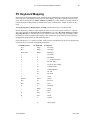
PC Keyboard Mapping...........................................................................................................................79
LIVE or LHV...........................................................................................................................................80
MAINTENANCE COMMANDS........................................................................... 81
HV MAINFRAME POWER-UP ........................................................................... 83
Sequence of Power-up Events ................................................................................................................83
Power-up Beep Sequence Variations.....................................................................................................84
Decoding Power-up Beeps .....................................................................................................................85
ERROR NUMBERS ........................................................................................... 87
HOST INTERFACE HARDWARE ...................................................................... 91
ARCNET..................................................................................................................................................91
ISABus (PC-AT) to ARCNET ..............................................................................................................91
VMEBus to ARCNET...........................................................................................................................91
CAMAC to ARCNET ...........................................................................................................................91
Ethernet....................................................................................................................................................91
SAMPLE CODE ................................................................................................. 93
Client.c - BSD Sockets client example ...................................................................................................93
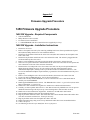
FIRMWARE UPGRADE PROCEDURE ............................................................. 99
1458-OM.DOC
ECO 1004
4
Table of Contents
1458 Firmware Upgrade Procedure ......................................................................................................99
1458 FW Upgrade - Required Components ..........................................................................................99
1458 FW Upgrade - Installation Instructions ........................................................................................99
1454 Firmware Upgrade Procedure ....................................................................................................100
1454 FW Upgrade - Required Components ........................................................................................100
1454 FW Upgrade - Installation Instructions ......................................................................................100
Proper Mainframe Power-Up Sequence..............................................................................................101
FIRMWARE VERSION HISTORY.....................................................................103
Introduction ...........................................................................................................................................103
Changes Since V1.01 .............................................................................................................................103
Changes Since V2.10 .............................................................................................................................104
Changes Since V2.14 .............................................................................................................................105
Changes Since V2.25 .............................................................................................................................106
Changes Since V2.34 .............................................................................................................................107
Changes Since V2.36 (1454), V2.51 (1458) ..........................................................................................107
Changes Since V2.73 .............................................................................................................................108
1454 BACKPANEL LAYOUT ...........................................................................109
1458-OM.DOC
ECO 1004
General Information
Purpose
This manual is intended to provide instruction regarding the setup and operation of the Model 1454 High
Voltage Mainframe. In addition, it describes the theory of operation and presents other information
regarding its functioning and application.
Unpacking and Inspection
It is recommended that the shipment be thoroughly inspected immediately upon delivery. All material in
the container should be checked against the enclosed Packing List and shortages reported promptly. If the
shipment is damaged in any way, please notify the Customer Service Department or the local field service
office. If the damage is due to mishandling during shipment, you may be requested to assist in contacting
the carrier in filing a damage claim.
Warranty
LeCroy warrants its instrument products to operate within specifications under normal use and service for
one year from the date of shipment. Component products, replacement parts, and repairs are warranted for
90 days. This warranty extends only to the original purchaser. Software is thoroughly tested, but is
supplied "as is" with no warranty of any kind covering detailed performance. Accessory products not
manufactured by LeCroy are covered by the original equipment manufacturers' warranty only.
In exercising this warranty, LeCroy will repair or, at its option, replace any product returned to the
Customer Service Department or an authorized service facility within the warranty period, provided that
the warrantor's examination discloses that the product is defective due to workmanship or materials and has
not been caused by misuse, neglect, accident or abnormal conditions or operations.
The purchaser is responsible for the transportation and insurance charges arising from the return of
products to the servicing facility. LeCroy will return all in-warranty products with transportation prepaid.
This warranty is in lieu of all other warranties, express or implied, including but not limited to any implied
warranty of merchantability, fitness, or adequacy for any particular purpose or use. LeCroy shall not be
liable for any special, incidental, or consequential damages, whether in contract, or otherwise.
Product Assistance
Answers to questions concerning installation, calibration, and use of LeCroy equipment are available from
the Customer Services Department, 700 Chestnut Ridge Road, Chestnut Ridge, New York 10977-6499,
(914) 578-6030, or your local field service office.
Maintenance Agreements
LeCroy offers a selection of customer support services. For example, Maintenance agreements provide
extended warranty that allows the customer to budget maintenance costs after the initial warranty has
expired. Other services such as installation, training, on-site repair, and addition of engineering
improvements are available through specific Supplemental Support Agreements. Please contact the
Customer Service Department or the local field service office for details.
1458-OM.DOC
ECO 1004
2
General Information
Documentation Discrepancies
LeCroy is committed to providing state-of-the-art instrumentation and is continually refining and
improving the performance of its products. While physical modifications can be implemented quite rapidly,
the corrected documentation frequently requires more time to produce. Consequently, this manual may not
agree in every detail with the accompanying product and the schematics in the Service Documentation.
There may be small discrepancies in the values of components for the purposes of pulse shape, timing,
offset, etc., and, occasionally, minor logic changes. Where any such inconsistencies exist, please be
assured that the unit is correct and incorporates the most up-to-date circuitry.
Software Licensing Agreement
Software products are licensed for a single machine. Under this license you may:
•
Copy the software for backup or modification purposes in support of your use of the software on a
single machine.
•
Modify the software and/or merge it into another program for your use on a single machine.
•
Transfer the software and the license to another party, if the other party accepts the terms of this
agreement and you relinquish all copies, whether in printed or machine readable form, including all
modified or merged versions.
Under this license you may not:
•
Make copies of the software except as noted above.
•
Distribute, in any form, any source code, or linkable object code.
•
Reverse engineer, decompile, or disassemble the software.
Firmware Licensing Agreement
A number of hardware products contained programmed parts which contain firmware. Under this license
you may:
•
Use the firmware only through the interface provided by the hardware product.
Under this license you may not:
•
Make copies of the firmware or the programmed parts containing the firmware.
•
Reverse engineer, decompile, or disassemble the firmware.
1458-OM.DOC
ECO 1004
Introduction
3
Service Procedure
Products requiring maintenance should be returned to the Customer Service Department or authorized
service facility. If under warranty, LeCroy will repair or replace the product at no charge. The purchaser is
only responsible for the transportation charges arising from return of the goods to the service facility. For
all LeCroy products in need of repair after the warranty period, the customer must provide a Purchase
Order Number before any inoperative equipment can be repaired or replaced. The customer will be billed
for the parts and labor for the repair as well as for shipping. All products returned for repair should be
identified by the model and serial numbers and include a description of the defect or failure, name and
phone number of the user. In the case of products returned, a Return Authorization Number is required and
may be obtained by contacting the RSD Customer Service Department, (914) 578-6030.
Licensed Products contained in 1450 series Products
The 1450 product line firmware and software is based on a number of software products licensed by
LeCroy and are distributed in accordance with these licenses. The following is an all inclusive list of
licensed products which may be have used in this product.
WATCOM C/C++, WATCOM, Inc., 42 Nagog Park, Acton, MA 01720-3409.
ROM-DOS, DATALIGHT, 307 North Olympic Ave., Suite 201, Arlingtion, WA 98223.
METAGRAPHICS, Metagraphics Software Corporation, 269 Mount Hermon Road, P.O. Box 66779,
Scotts Valley, CA 96055
INTERWORK PROFESSIONAL, Block Island Technologies, 15455 N. W. Greenbrier Parkway, Suite
210, Beaverton, OR 97006.
PHAR LAP TNT DOS-EXTENDER RTK, Phar Lap Software, Inc., 60 Aberdeen Avenue, Cambridge,
MA 02138.
SYSKIT, Annabooks, 15010 Avenue of Science, Suite 101, San Diego, CA 92128.
PKSFX, PKWARE, Inc., 9025 N. Deerwood Dr., Brown Deer, WI 53223.
1458-OM.DOC
ECO 1004
Chapter 1
Introduction
Product Description
Overview
The LeCroy 1454 and 1458 High Voltage (HV) mainframes provide support for LeCroy 1460 or 1470
series HV modules. A 1454 can house as many as four (4) modules while a 1458 can support up to sixteen
(16) modules.
A 1454 HV mainframe includes a complete local user interface, a 1458 does not. However, a suitable local
interface for the 1458 can be implemented by the user with the addition of VT100 compatible video
terminal.
Otherwise, the operational characteristics of 1454 and 1458 mainframes are nearly identical. The term “the
1454/8 HV mainframe” or more simply “the HV mainframe” will used throughout this manual in reference
to those operational features jointly supported by a 1454 or a 1458 HV mainframe.
The 1454/8 HV mainframe contains two separate remote interfaces, RS-232 and ARCNET, to provide
additional access to both users and host computer systems. A third optional interface Ethernet (1450-ET) is
available which supports access using the TCP/IP protocol via TELNET, FTP, or BSD Sockets.
The HV mainframe allows the operator to utilize all the features of the HV module. Usually, these include
a) enable HV generation, b) set ramp rates, c) set target voltage, d) set current and voltage levels for
tripping, e) examine voltage and current measurements, on a per channel basis. Further, the mainframe
allows the user to maintain HV limits, save and restore complete HV module configurations, lock module
settings or limits, enforce safety interlocks, and interface to computer networks.
The HV mainframe is designed to accommodate new (yet to be designed) HV modules. The mainframe
controller queries each installed module (in a general fashion) in order to determine the requirements and
features of the particular module. General commands and/or front panel/VT100 operations allow control
and display of a module’s configuration.
Vertical Airflow Version
The standard 1458 version has been modified to allow vertical air flow for the primary cooling mechanism.
Additional Fan’s are to be supplied by the customer. With the top and bottom covers removed the Fan’s
must be place on either the top or bottom of the crate blowing from bottom to top. Three 105CFM Fan’s
are needed to cool the power supply section and three 105CFM fans are required to cool the card cage
section. Under no circumstance should a crate be operated without proper cooling.
1454 Local Interface
The 1454 local interface includes a 320 x 240 pixel LDC display and a custom keypad mounted to the front
panel of the 1454 HV mainframe. With the keypad, all of the 1454 HV mainframe features are accessible.
The data are presented in a spread-sheet style with several different formats available. Pop-up menus are
used for system configuration.
1458-OM.DOC
ECO 1004
6
Introduction
1458 Local Interface
The 1458 local interface includes only buttons for turning on or off HV generation and a panic off button
and a few LED indicators. By connecting a VT100 compatible terminal to the mainframe serial port all of
the HV mainframe features are accessible. A VT100 (full-screen, editing) display can be activated wherein
data are presented in a spread-sheet style with several different formats available. Pop-up menus are used
for system configuration.
Remote Interfaces
Three (two standard and one optional) hardware interfaces are provided for remote command and control.
The first is the RS-232 serial interface suitable for control by a host computer or an ANSI video terminal.
The serial interface provides both a command line and a VT100 (full-screen, editing) interface for an HV
mainframe.
The second remote interface is an ARCNET network interface. Multiple HV mainframes connected to a
single ARCNET network can be easily controlled from a single host. A mainframe’s ARCNET address is
determined by the switches above the ARCNET BNC connection.
The optional remote interface is an Ethernet network interface (1450-ET). Three higher level TCP/IP
application protocols are supported TELNET, FTP, and BSD sockets. Typically, the BSD sockets protocol
is used with host control applications. The mainframe’s IP address and other TCP/IP features are setup via
the front panel display for a 1454 or via the RS-232 interface for the 1458.
Both the serial, ARCNET and Ethernet interfaces use the same ASCII-commands with slightly different
message termination sequences. In the case of the serial command line and Ethernet TELNET interfaces, a
command prompt is issued to inform the user that the mainframe is ready for the next command. The
ARCNET and Ethernet BSD socket command protocols use a continuation character field to indicate the
last response message and readiness for the next command.
Remote control of a HV mainframe via ARCNET (or Ethernet) is much more efficient than RS-232
control. For example, ARCNET has a character transmission time of less than 4 microseconds while this
time for 19.2Kbaud RS-232 is nearly half of a millisecond. Since ARCNET is a message based protocol,
the HV mainframe CPU only processes complete command messages when this remote interface is used.
For
RS-232, each character of the command must be serviced by the CPU which slows processing of command
messages and the mainframe’s update rate.
Safety Interlocks
A Panic Off condition simply prevents any HV generation by removing the necessary power from the HV
modules. This condition can be reached in two ways. The simplest is by pressing the front panel PANIC
OFF button. A Panic Off condition can also be caused by not grounding the INTERLOCK input port..
A Panic Off condition is indicated by the illumination of the two red LEDS on either side of the PANIC
OFF button. HV generation cannot be turned on (via the HVON button or a HVON command) until the
Panic Off condition is cleared.
Once the reason for a given Panic Off condition has been addressed, the condition can be cleared via the
HVOFF button on the HV mainframe front panel only if the front panel key switch is in the LOCAL
position.
Also for safety reasons, HV generation can always be turned off (at programmed ramp down rates) via the
HVOFF front panel button or a remote “HVOFF” command independent of the front panel key switch
position or any other “restricted access” operating mode.
1458-OM.DOC
ECO 1004
Introduction
7
Rear and Front Panel Power Switches
Two power switches are provided. The rear panel rocker switch controls the AC power to the entire HV
mainframe. The front panel key switch, STANDBY position disables power generation, except for a small
housekeeping supply. When the front panel key switch is in the STANDBY position, the internal mainframe
power is off and HV generation is impossible. The REMOTE and LOCAL positions of the front key switch
controls the source of HV setting edit operations, as discussed in a later section.
By factory default, the HV generation is not enabled upon power-up. However, as discussed in the
“Automatic HV On after AC power failure” section, the HV mainframe can be configured to automatically
restore HV generation after an AC power failure or a mainframe power down caused by the rear panel
rocker switch.
External BNC Connections
There are three BNC’s (located on the rear panel of the 1454 and on the front panel of the 1458) providing
the INTERLOCK input, STATUS output, and MACRO input ports. (The Installation and Checkout section
of this manual chapter, shows schematically the location of these ports in the Remote Interface Panel
figures for the 1458 and 1454.)
The INTERLOCK port causes an HV Panic Off condition when it is not grounded. The operational
characteristics of the STATUS and MACRO ports are determined by “system default” settings (discussed
in a later section).
When the mainframe power is off the STATUS output floats. Immediately upon power-up the STATUS
output is clamped to ground. Once the HV mainframe is “Ready” (after the NETWORK and REMOTE
LED’s have stopped flashing), the STATUS output level is determined by the mainframe system defaults.
The STATUS output port can be configured to clamp to ground on any or all of the following conditions: 1)
Panic Off, 2) any channel being tripped off, or 3)HV generation is disabled (HVOFF).
The MACRO input port can be configured to turn off HV generation when the input is clamped to ground.
The HV mainframe also supports modules (yet to be designed) which provide an alternate setup (of HV
settings) by using the MACRO input to signal the selection of the alternate setup.
A typical use of the STATUS and MACRO signals could be to cause HV generation to be turned off on a
group of mainframes when any HV channel trips off in that group.
Mainframe DC Power Considerations
In order to optimize price/performance for a variety of applications, 1454 and 1458 mainframes can be
factory configured for different output power capabilities. A standard 1454, while suitable for a number of
applications does not , for example, provide the ability to supply full voltage along with full output current
simultaneously for all channels for four 1461 modules. A higher powered 1454, the 1454hp is available to
furnish sufficient power for such applications.
The 1458 mainframes also comes in two possible power configurations, 1458 and 1458hp. The 1458hp is
the high power configuration.
Detailed information on the output power capabilities of these mainframe configurations should be
obtained from LeCroy technical data sheets. The amount of current provided on the mainframes 24V
supply determines the module output power capability (since it source for the module’s HV generation). As
a rough guide, the 1454 and 1454hp mainframes contain 15A and 30A 24V power supplies. While the
1458 and 1458hp contain 60A and 90A 24V power supplies.
1458-OM.DOC
ECO 1004
8
Introduction
Installation and Checkout
Installation Accessories Kit
The 1454 and 1458 mainframes come with a few accessories (listed below) to aid in their installation. In a
following section, the remote interface panels of the 1454 and 1458 are shown schematically to help locate
mainframe input/output ports..
BNC Tee
BNC 90 Ohm Terminator
BNC 50 Ohm Terminator
110 VAC Power Cord
210 VAC Power Cord (1458 Only)
The BNC Tee and the 90 Ohm Terminator are for use with the ARCNET interface card. Even if you do not
intend to use the ARCNET interface, it is recommended that the BNC Tee and 90 Ohm terminator be
connected to ARCNET BNC port so that these parts are not lost.
For checkout purposes the BNC 50 Ohm Terminator should be connected to the INTERLOCK port to
inhibit the interlock driven PANIC OFF conditions. The INTERLOCK port causes and actively maintains
a PANIC OFF condition when it is not grounded.
The 1458 mainframe includes both 110 VAC and 210 VAC power cords. As discussed in the following
paragraphs, a 1458 should generally be operated at the higher AC Voltage. Although for the simple
mainframe checkout 110 VAC should suffice.
AC Power
LeCroy 1454 and 1458 mainframes will typically operate with AC power in the range of 90 VAC to 260
VAC and 50 to 60 Hz (power factor corrected). However, the 1454 and 1458 AC power connections are
configured with a 15A circuit breaker which can limit the amount power available when lower AC voltages
(110 VAC) are used.
Indeed, in most 1458 applications a high AC voltage (210 VAC) is required in order to deliver sufficient
power for HV module operations. Although, for low power operation of modules (as might be
encountered in control software development) operation at a lower voltage (110 VAC) should be adequate
for both 1454’s and 1458’s.
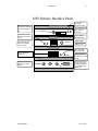
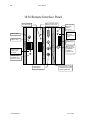
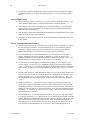
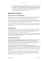
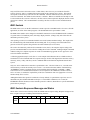
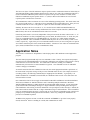
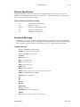
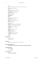
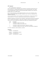
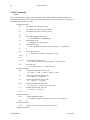
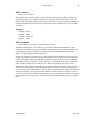
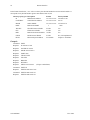
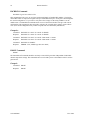
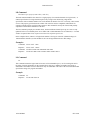
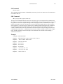
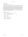
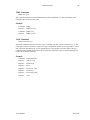
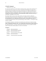
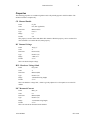
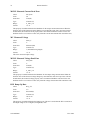
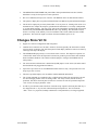
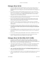
Remote Interface Panels
Shown schematically on the following pages are the remote interface panels for the 1454 and 1458. Notice
that the relative placement of the control ports is different for the two mainframes. Also notice that the
switch block which controls the 1458 serial port baud rate serves no function for the 1454. (The 1454 baud
rate is set using the front panel interface via the System Menu.)
The typical operation of LEDs and switches is indicated in these drawings. Please consult the Remote
Interfaces chapter for a detailed explanation on the operation of the various remote command ports (Serial,
ARCNET, or Ethernet). The Ethernet interface (1450-ET) is an optional mainframe feature.
1458-OM.DOC
ECO 1004
Introduction
9
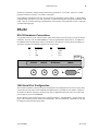
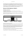
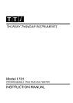
1458 Remote Interface Panel
BNC T and 90 Ohm
Terminator for ARCNET
included in installation
kit.
ARCNET 0 --------------------- 7
Red ARCNET LED
blinks upon
mainframe access.
Green ARCNET LED
blinks when no
connection.
Yellow Ethernet LED
blinks upon mainframe
access.
Factory default
ARCNET port is 7.
ETHERNET
10Base-2 BNC
Green Ethernet LED
lights when 10Base-T
plug connected.
10Base-T Plug
1458 BAUD RATE
Green LED lights
when Power ON
Factory Default 9600
Baud for Serial Port
(1458 Only)
STATUS
STATUS output level is
dependent on system
defaults.
1458-OM.DOC
MACRO
INTERLOCK
SERIAL
Green LED blinks
slowly indicating clock
activity.
Ground Interlock with
50 Ohm Terminator
included in installation
kit to inhibit Interlock
PANIC OFF.
ECO 1004
10
Introduction
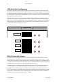
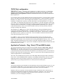
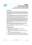
1454 Remote Interface Panel
Green LED blinks slowly
indicating clock activity.
10Base-2 BNC
MACRO
ETHERNET
INTERLOCK
10Base-T Plug
STATUS
Green Ethernet
LED lights when
10Base-T plug
connected.
Yellow Ethernet
LED blinks upon
mainframe access.
STATUS output level
is dependent on
system defaults.
1458-OM.DOC
ARCNET 0 --------------------- 7
SERIAL
Green LED lights
when Power ON
Green ARCNET
LED blinks
when no
connection.
Red ARCNET
LED blinks
upon mainframe
access.
Factory default
ARCNET port is
7.
BNC T and 90
Ohm Terminator
for ARCNET
included in
installation kit.
Ground Interlock with 50
Ohm Terminator included
in installation kit to inhibit
Interlock PANIC OFF.
ECO 1004
Introduction
11
Checkout
The following is a brief procedure which may be used to both confirm and familiarize the user with the
proper operation of a 1454 or 1458 HV mainframe. For a 1458, the complete checkout requires a nullmodem serial cable used in conjunction with a VT100 compatible terminal. The terminal should be setup
for 9600 baud (factory default), 1 stop bit, 8 data bits and no parity then connected to the 9-pin serial port
of the 1458’s remote interface panel.
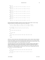
Power-up
1.
Install at least one HV module if available.
2.
Assure that the INTERLOCK port is grounded. Use the 50 Ohm terminator supplied.
3.
Plug in AC power and flip rear panel power switch on.
4.
Turn the front panel key switch to LOCAL for a 1454. For a 1458 set this key switch to
REMOTE.
5.
Observe that the fans startup immediately and that the mainframe issues 1or 4 beeps ,
although the 1454 display remains blank for almost 10 seconds. After about 15 seconds the
front panel REMOTE/LOCAL LED’s should blink.
6.
When the REMOTE/LOCAL LED’s have finished flashing, observe 1 or 2 beeps. If no
modules are installed, 2 beeps will be issued repeatedly. (If no modules are installed, the
mainframe will accept remote interface commands which do not require HV module
information like SYSINFO, ENET, etc.)
7.
The rest of this procedure assumes that at least one HV module was installed. Do not proceed
to the following steps until after the REMOTE/LED LED flashing has stopped.
Setting a Channel’s Voltage and Enabling a Channel
8.
For a 1454, you may need to hit the ENTER button twice to get to the standard spread-sheet
style display of HV channels vs. values.
9.
For a 1458, use the VT100 terminal and hit a carriage return to display the prompt “0\Enter
“1450” to begin>”. Type “1450” and a carriage return to display the prompt
“1\EDIT\1450>”. Type “VT100” and a carriage return to activate a full screen display
similar to the 1454 display. Notice that the right hand side of the display contains a mapping
of button actions to terminal keys.
10. If the mainframe PANIC OFF is active, use the front panel switch to set the mainframe in
LOCAL mode (REMOTE LED not on). (Notice that the 1458 drops out of the VT100 display
mode in local mode.) Use the front panel HVOFF to reset the PANIC OFF. If the
INTERLOCK port is not grounded the INTERLOCK LED should be ON and pushing the
HVOFF will have no effect.
11. Notice that the arrow keys and previous page (VT100 terminal character “<PF1>”) and next
page (VT100 terminal character “<PF2>” allow movement around a large sheet of parameter
settings and measured values. Use the module keys (terminal characters “<SHIFT>0”
through “SHIFT9 then “A” through “F”) to jump to first channel of a module in a given slot.
12. To set a voltage use the front panel keypad arrow buttons (or terminal keyboard arrow keys)
to highlight a target voltage value (not a measured voltage). Use the keypad (or the
keyboard) to enter a voltage setting. Use ENTER to cause the mainframe to accept the new
setting.
1458-OM.DOC
ECO 1004
12
Introduction
13. Use the 1454 CHANNEL ENABLE button (on the right next to HVON and HVOFF buttons),
to enable this channel. For a 1458, the terminal character “[“ serves as the channel enable
button.
Turn on High Voltage
14. Observe that a dot appears on under the “S” or status column for the enabled channel. Turn
on the mainframe high voltage by using the HVON button (or terminal character “{“).
15. Observe that the dot becomes an small up arrow (or terminal character “^”) as the enabled
channel ramps up to its target voltage. Also, observe the front panel HVON LED flicker
during the high voltage ramping.
16. Once the target voltage has been attained, the dot indicating an enabled channel is once again
displayed and the HVON LED remains on.
17. Set voltages for other channels as desired. Notice that the channel enable/disable keys work
in any column.
Tour of Selected Mainframe Features
18. Turn the mainframe power off by switching the front panel switch to STANDBY or switching
the rear panel power switch off. Turn the mainframe power on again and notice after the
power-up is complete (and the 1458 VT100 display has been started up again) that the
channel value settings are restored to those before the power was switched off.
19. Use the SYSTEM button (or the terminal character “s”) to investigate the system menu
features. Submenu items may be selected via number keys or using the arrow keys to
highlight a menu item of interest then hitting ENTER or SELECT (or terminal “<CR>”). The
ESCAPE button (or terminal character “e”) is used to exit a given menu.
20. From the main spread sheet display use the Display Up button (or “u”) to display a list of
possible displays. Use the arrow keys to highlight a display of interest then hit ENTER ( or
“<CR>”) or SELECT (or “>”) to activate that display or simply hit the number in front of the
display name.. To get back to the main spread sheet display hit Display Up (or “u”) then hit
“0”..
21. From the main (channel vs. value) spread sheet display, select a range of target voltages to be
set to the same value as follows: 1) Use the arrow keys to highlight the first channel’s target
voltage, hit SELECT (or “>”). 2) Use the arrow keys or next page button (or “<PF1>”) to
move highlight down to last channel in range. 3) Enter a new value followed by ENTER (or
“<CR>”).
22. The DELTA button (or “/”) operates in a manner similar to SELECT in the previous step
except values entered are interpreted as amounts to add or subtract from the current settings.
After hitting the delta key, notice the little arrow indicator in the edit window which indicates
whether the value will increase or decrease the absolute value of the selected channel settings.
The polarity, +/- , button (or “p”) allows the user to change a delta operation back and forth
between an increase or decrease.
23. The INCREMENT (or “i”) and DECREMENT buttons (or “d”) allow for single digit changes
in a setting. Use SELECT (or “>”) then the arrow keys to position the place marker in the edit
window. Hitting increment(decrement) keys increase (decrease) this place value by one. The
new value does not take effect until you hit ENTER. Notice that moving the highlight to a
new setting preserves the place marker such that simply hitting the increment or decrement
keys takes that action immediately on the current place value (without hitting SELECT).
1458-OM.DOC
ECO 1004
Introduction
13
24. There is some online help available via the HELP button (or “h”). However, you will most
likely be frustrated by the small screen of the 1454 or slow response for a terminal. The same
help information is available as a MS Windows help file (hvhelp.hlp) downloadable from the
LeCroy ftp site (www.lecroy.com). The help feature is intended as quick reference for simple
day-to-day operations. The information in this file is inevitably dated. This manual is
typically more up-to-date and contains much more detail.
Operational Features
Remote versus Local Operations
When the front panel key switch is in the REMOTE position, local control of the unit is disabled. In this
condition, the user may locally view but not edit HV settings. When the front panel key switch is in the
LOCAL position, a remote user may only issue commands which do not change HV settings.
For safety, a user is permitted to turn off HV generation either remotely or locally independent of the front
panel key switch position. However, the HV generation can only be turned on remotely if the front panel
key switch is in the REMOTE position and locally if it is in the LOCAL position.
The HV PANIC OFF button, which immediately turns off HV generation, is always operable in either key
position. Operation of the STATUS output and the MACRO and INTERLOCK inputs are also independent
of the key position.
HV Generation
Once the HV mainframe CPU has started, the unit restores the HV settings as they were when the unit was
turned off or the AC power was removed. Unless changed from the factory default (See the “Automatic
HV On after AC power failure” section), the mainframe DOES NOT restart HV generation. A user
command or front panel operation is required to begin HV generation.
Even though HV generation is indicated as ON, whether or not a given channel supplies HV depends on
whether the channel is enabled, the channel’s target voltage, ramp up rate, and trip condition. All of the
former settings are observable and controllable.
Save and Restore Sets
The HV mainframe includes battery backed-up memory, which provides storage for save sets. Save sets are
accessed via the SAVE and RESTORE buttons on the front panel or via remote commands. A save
operation places the current configuration and settings in a save set. The set name is shown in the save
menu with time and date of the save operation. Save sets are only valid for a specific module configuration
determined by the model number and the slot location of the installed modules. This allows direct
replacement of HV modules with no loss of configuration data.
The mainframe also maintains an internal power-up save set which always reflects the current
configuration and settings. On power-up, if the installed module configuration has not changed, the settings
at the time of the last power-down are restored. If a different module configuration is detected, none of the
settings are restored and all modules start with their factory default values (typically target voltages zero.)
The 1454 mainframe issues a warning and pauses in its power-up sequence if the previous settings cannot
be restored.
By factory default, the HV generation condition is NOT restored on power-up or as part of a named save
set restore operation. However, the HV mainframe can be configured to automatically restore HV
generation after an AC power failure or a power down caused by the rear panel rocker switch. (See the
“Automatic HV On after AC power failure” section.)
1458-OM.DOC
ECO 1004
14
Introduction
The power-up save sets for a previous module configuration are not lost until after the first change of the
module settings in the current configuration. Named save sets which are invalid for a new configuration are
not lost until overwritten with a new save set.
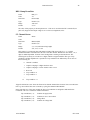
System Defaults, STATUS, and MACRO
System defaults refer to a group of HV mainframe operating features which can be user configured and are
generally independent of module and communications setup. System defaults can be configured locally
(1454 only) or by remote command (SYSDEF).
System default features include the ability to: 1) disable/enable the 1454 mainframe from automatically
switching to the large font three-line display after 1 minute with no key input, 2) enable/disable the remote
password, 3) configure the STATUS output signal, 4) configure MACRO input signal, and 5)
enable/disable the automatic restoration of HV generation after an AC power failure or a power down via
the rear panel rocker switch. (See the “Automatic HV On after AC Power Failure” section.)
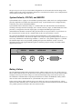
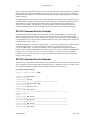
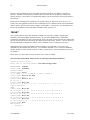
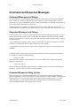
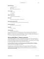
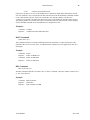
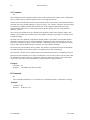
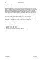
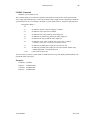
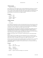
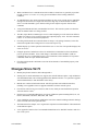
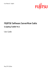
The STATUS and MACRO ports are located on the HV Mainframe’s remote panel interface as
schematically shown below. The STATUS output can be setup to clamp to ground upon the occurrence of
each or any combination of the following conditions: 1) Panic Off 2) any channel tripped or 3) HVOFF.
The MACRO input can be setup such that grounding the input causes HVOFF. (Future versions of
mainframe firmware will support MACRO signals use alternate groups of settings, for modules which
support such a feature.)
STATUS
MACRO
INTERLOCK
SERIAL
Battery Failure
The HV mainframe includes battery backed-up memory which is used to store save sets. In the event of a
battery failure while the power is off, data in save sets may be lost. When save sets are lost, default module
settings (not the last power down settings) are restored with the high voltage off on the next power-up.
The mainframe's communications setup and system defaults are stored in an EEPROM, a battery failure
does not effect remote communications or system defaults once power is restored.
In the event of a battery failure while the power is on, data in save sets are not necessarily lost. A large
capacitor provides sufficient power to retain data for several hours after the mainframe is turned off. In this
case, prompt replacement of batteries does not result in lost data.
1458-OM.DOC
ECO 1004
Introduction
15
Software Limits
The HV mainframe supports software limits for all settable module parameters. These limits can be set on a
per channel basis and set an upper bound to the absolute value of any entered setting. Attempts to set
values greater than this limit are blocked and cause an error message to be issued. The default limits are
determined by the HV modules and are typically independent of a module’s hardware HV limit. Software
limits are NOT included in named save sets; but, they are included as part of the power-up save set.
Hardware High Voltage Limits
Some HV modules have a hardware controlled, adjustable HV limit. This type of limit cannot be violated
by any remote or local commands. The result of attempts to operate beyond the these limits is dependent on
the HV module type.
Trip Conditions
Typically, HV modules can promptly disable or trip off a channel’s HV generation without any action by
the HV mainframe. Once a trip condition occurs the tripped channel can be re-enabled once the cause for
the trip has based addressed. Possible causes for trips are dependent on module type. However, typical
causes for trips include 1) exceeding the current or voltage trip limits set by the user, 2) exceeding the HV
the current/voltage capability of a module, 3) attempting to operate a module above its Hardware Voltage
Limits, 4) a fault which prevents the unit from maintaining a set value, 5) thermal overload.
Because of the local monitoring and trip capability HV modules, there is typically no need for close
monitoring by a external host to compare measured to set HV values. Rather, channel status values are
available which indicate trip conditions, whether a channel is enabled or disabled, and whether it is
ramping up or down.
Locking of HV Settings or Software Limits
In order to prevent inadvertent or unauthorized changes to either HV settings or software limits, the HV
mainframe supports the “locking” of these values via remote command or local front panel input. The
locking of HV settings is completely independent of the locking of software limits.
As part of the locking procedure the user must supply a 4-digit PIN (personal identification number). HV
settings (or software limits) which are locked cannot be changed until the 4-digit PIN is supplied causing
these values to become unlocked. Once all value changes have been made, the unlocked condition remains
until the user explicitly locks the values with a PIN. The HV mainframe does not remember a given PIN
after it is has been successfully used to unlock values. Locking/unlocking of values is independent of the
front panel key switch setting (local or remote).
Even though HV settings have been locked, HV generation can be turned on or off without unlocking
values or supplying the 4-digit PIN. In the event a PIN has been forgotten, the user can unlock both HV
setting and software limit locks by powering up the HV mainframe with no modules plugged into the
mainframe backplane. Once the HV mainframe power-up is complete (less than 1 minute) and no modules
are found (repeated double beeps), all value locks are unlocked.
Setting and software limit locks are stored in the same as save sets and thus are affected in the same way as
save sets by a battery failure (see the “Battery Failure section).
1458-OM.DOC
ECO 1004
16
Introduction
Automatic HV On after AC Power Failure
By factory default, the HV mainframe is configured to require a user operation or command to initiate HV
generation. However, the mainframe can be configured to restore HV generation after an AC power failure
or a mainframe power down via the rear panel rocker arm switch.
If this feature is enabled and the AC power is removed while the mainframe is actively generating HV then
after the AC power is restored and module settings have been successfully restored, the mainframe begins a
10 second countdown (one beep/sec) during which the user may abort (via front panel keystroke) the
pending HV On operation. During this countdown the front panel HVON LED’s flash, but the mainframe
is not generating HV. (Note, that once the countdown expires and HV generation begins these LED’s will
flicker (indicating ramping HV).
This feature is automatically disabled and remains disabled until explicitly enabled as a system default
when any of the following conditions occur: 1) a new or no module configuration is detected, 2) an error
is detected when restoring mainframe or module settings , 3) the mainframe PANIC OFF button has been
hit, or 4) the mainframe has undergone a reset because of some internal error.
Thermal Overload Protection
The HV mainframe power supply subsystems have thermal overload protection. The following system
conditions result in the event of a thermal overload:
1) The 24 Volt supply to the HV modules is cut off preventing modules from generating HV.
2) Typically, HV modules with enabled channels will register a “voltage” trip condition if HV is
On without the 24 Volt supply.
3) The HV mainframe will turn off HV generation placing the mainframe in the HVOFF state. 4)
The 1454/VT100 display will issue a warning message at the top of the display.
5) The CONFIG command will return status information indicating the 24V is bad.
A thermal overload does not cause a PANIC OFF condition. However, since the mainframe system does go
to the HVOFF state when a thermal overload is detected, the STATUS output (if configured to be
sensitive to HVOFF) provides an indirect hardware indication of a thermal overload..
Most HV modules have thermal overload protection independent of the HV mainframe and indicate an
overload via a channel trip condition code. Consult the module’s manual for further information.
Once the reason for the thermal overload has been addressed, the HV mainframe can be reset by cycling
the AC power.
Mainframe Maintenance
To facilitate the maintenance of HV mainframes (by, for example, an equipment pool technician) certain
mainframe features can be overridden by powering up the mainframe with no modules. When powered
with no modules the mainframe clears all setting and software limit locks, disables remote passwords, and
disables the “restore HV after ACFAIL” feature (if enabled) until explicitly enabled by user. When the
previous actions are complete the mainframe issues a specific repeating beep code sequence (indicating no
modules found). (See the appendix “HV Mainframe Power-up. )
1458-OM.DOC
ECO 1004
Chapter 2
Local Operation
The 1454 Front Panel
Keys
The 1454 mainframe front panel has a number of control keys appropriately grouped according to their
function. Typically, keys close to the display do not change the current settings.
The HardCopy key brings up a menu for printing (not supported at this time).
The Save and Recall keys save and restore configuration data in save sets.
The Help, Prev Page, Arrow, Next Page, Select keys, and Module 0-3 keys move the cursor in
the current display and select data for modification.
The System, Group, Chan, Display Up, Previous, Next, and Display Dn keys control which
display is active.
The Numeric (0-9 & “.”), ESC, Backspace, Increment, Decrement, Delta, and “+/-” (Polarity)
keys are used to edit numbers.
The Enter key transfers the edited numbers to the data base, thus altering the current settings.
The Channel Enable/Disable and the HV On/Off keys control HV generation.
The Panic Off key immediately terminates HV generation on all channels.
Lights
The 1454 mainframe front panel indicator LED’s include: Panic Off, HV Error, Interlock Error,
HVON, Remote, Network, System, Group, Chan, and Module 0-3 lights.
The Panic Off lights come on when a panic off condition exits. If the panic off condition was caused by an
external interlock signal, the Interlock Error light will be on. The HV Error light flashes when one or
more HV channels are in a tripped condition. The HVON light flashes when the HV is ramping up or
down and remains on when HV generation is active and stable. The Remote light is on when local editing
of values has been disabled. The Network light is on when the external network is active. The System,
Group, and Chan lights indicate which display type is active. Slots which have installed modules are
shown by their associated Module 0-3 lights. These same lights flash when a channel in the designated
module is ramping or is tripped.
1458-OM.DOC
ECO 1004
18
Local Operation
The 1458 Front Panel
Keys
The 1458 mainframe front panel has only two control keys. The HV On/Off keys control HV generation
and the Panic Off key immediately terminates HV generation on all channels. Control of HV settings with
a 1458 mainframe should done via a remote interface.
Lights
The 1458 mainframe front panel indicator LED’s include: Panic Off, HV Error, Interlock Error,
HVON, Remote, and Network lights. These lights all operate in the same manner as described in the
lights section for the 1454 front panel.
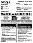
Display and Control
1458 Local Display
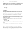
The remainder of this chapter would seem to discuss the use of the 1454 front panel to control HV modules
and display HV module values. However, a “local” display for the 1458 which operates in a fashion similar
to the 1454 display is available.
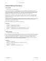
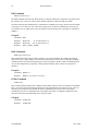
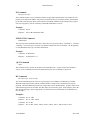
By connecting a VT100 video terminal to the 1458 serial port, a control/display interface can be started
wherein each of the 1454 front panel keys correspond to standard VT100 keys or key combinations as
listed on the next page. To start this control/display interface consult the “Remote Interface” chapter and
documentation on the VT100 command. The VT100 control/display interface is also available for the 1454
HV mainframe.
1458-OM.DOC
ECO 1004
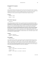
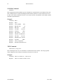
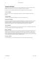
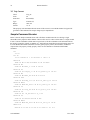
Local Operation
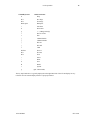
VT100 Keyboard
19
1454 Front Panel
h
Help
PF1
Prev Page
PF2
Next Page
Back Space
Backspace
i
Increment
d
Decrement
p
+/- (Change Polarity)
r
Reverse Video
e
ESC
[
Channel Enable
]
Channel Disable
{
HV ON
}
HV OFF
c
Chan
Shift0-3
Slot 0-3
PF3
Previous
PF4
Next
>
Select
/
Delta
S
Save
R
Recall
s
System
q
(quit VT100 mode)
The key map listed above is typically displayed on the right-hand side of the VT100 display for easy
reference once the control/display interface is properly initiated.
1458-OM.DOC
ECO 1004
20
Local Operation
The Spread Sheet Paradigm
The channel vs. value display is one of many spread sheet-like formats for presenting module settings and
measurements. The user interface is similar to a large spread sheet which extends beyond the limits of the
display.
The display is typically divided into two areas, a small edit box at the top of the display and a larger sheet
display area.
The edit box generally contains information on the channel values highlighted in the sheet below. Inside
the edit box is the edit value area. Data highlighted in the sheet below also appears in this area if it can be
edited. The edit value area is highlighted when an edit or data entry operation is active.
Small arrow-like indicators along the border of the sheet display indicate where additional information can
be brought into view. A small flashing heart, in the upper left corner of the display shows when the
display is live. Each time a scan of all modules for their measurements is completed the heart is toggled on
or off. The display update rate is twice the blink rate of this heart.
The current HVSTATUS is displayed on the upper right corner of the display. The title of the current
sheet is displayed in the middle of the top edge of the display. Error messages are generally written on the
bottom border of the display.
Moving Around and Simple Value Entry
The Arrow, Prev Page (Page Up)= , and Next Page (Page Down) keys move the cursor around the sheet
display, bringing into view values of interest. The Module # (Alt-#) keys jump to the beginning of a
specific module.
When a sheet value is highlighted and also appears in the edit box, it is a settable value. Simply entering a
numeric value begins a data entry operation. The Enter key causes the value in the value edit box to be 1)
checked against limits, 2) sent to the HV module, and 3) replaced by the actual value registered by the HV
module. A number of value entry/editing modes are supported which are discussed in a later section.
Although the first sheet displayed is the Channel vs. Value sheet, other sheet formats can be displayed with
the Previous (F7) and Next (F10) keys. A number of these sheets simply display a given property value
for all channels. Repeated use of either a Previous (F7) or Next (F10) key will eventually go through all
possible sheets and loop back to the initial sheet.
The Channel vs. Value Sheet
The first sheet, Channel vs. Value, has columns headed by property names and rows headed by channel
numbers. Channel labels include an indicator dot which if visible indicates that a given channel is enabled
and stable. The channel status of the value highlighted in the sheet display is presented in the right corner
of edit box.
Immediately after HVON (F5) is initiated, enabled channels which have non-zero (but reasonably low
ramp up rates) have a ramp up status indicated in the channel label with an up-arrow. Once an enabled
channel’s target voltage has been achieved, its status character becomes a dot again. Turning off the HV
with HVOFF (F6), causes the channel status character to become a down-arrow (for a reasonably low
ramp down rate). Once an enabled channel has reached ground potential, its status character becomes a dot
(if it is enabled).
=
The equivalent key used from a PC keyboard (NOT a VT100 terminal) is given here and later in parentheses for
convenience of those using the PC simulation SW or the HV51 control program.
1458-OM.DOC
ECO 1004
Local Operation
21
For the Channel vs. Value sheet and many other sheets, the Channel Enable (F3) and Disable (F4) keys
may be used to enable/disable a channel or a series of previous selected channels. Selecting any value or
series values (as discussed in the following section), selects the associated channel(s) for the possibly of
being enabled/disabled.
Channels which exceed their trip current settings become tripped and the channel status character flashes,
first a ramping down indication, then an exclamation point “!”. To clear a trip condition(s) select any value
of the tripped channel(s) and press the Channel Enable (F3) or Disable (F4) key.
Value Entry and Editing
If the value highlighted in the sheet display also appears in the value edit box, then this is a value which
may be modified. A number of value entry and editing modes are supported. These include 1) simply
entering a new value, 2) changing a specific character in the current value, 3) incrementing and
decrementing the current value, 4) selecting a series of channels to receive an entered value, and 5)
applying a delta value to be added to current value.
The value edit box is highlighted when an entry or edit operation is in progress. Hitting the ESC (e) key at
any time prior to completion of the edit operation with an Enter key, terminates the operation with no
change in value(s).
Entering A New Value
The value to be replaced should be highlighted in the display sheet and appear in the value edit box. The
first Numeric key entry clears the edit value area and inserts the character in the left most position.
Additional Numeric key entries build the numeric value in the conventional way.
The Left and Right arrow keys may be used to position the cursor inside the enter character string.
Entered characters are inserted into the string at the cursor position. The Backspace key deletes characters
to the left of the cursor.
The Increment (i) and Decrement (d) keys add and subtract one from the digit indicated by the cursor.
Increments increase and decrements decrease the absolute value of the entered character string. Rollovers
to the next digit are done correctly. This allows any value to be quickly stepped in 1’s, 10’s or 100’s (or
any other decimal location available).
Generally, the appropriate sign for a value is maintained in the edit value area. To change this value’s sign
use the “+/-” or Polarity (p) key.
Editing an Existing Value
The value to be edited should be highlighted in the display sheet and also appear in the edit box. Hitting the
Select (Home) key activates an edit operation indicated by the highlighting of the edit value area. All key
operations discussed in the “Entering A New Value” section may now be used to edit this character string.
Incrementing or Decrementing an Existing Value
The Increment (i) or Decrement (d) key immediately starts an edit session and changes the digit under the
edit cursor. The edit cursor position is saved from last edit session. Additional keystrokes continue to
modify the data in the edit value window, but the data is not transferred to the HV module until the
operation is completed with the Enter key.
For example, when incrementing the same value by repeatedly hitting Increment (i) followed by Enter
will cause each new value to be registered by the HV module in question.
If the current cursor indicator is not at the desired location for an increment or decrement operation, hit the
Select (Home) key then use the Left or Right arrow keys to position cursor as desired.
1458-OM.DOC
ECO 1004
22
Local Operation
Selecting a Series of Channels for Value Entry
The first channel value in the series is highlighted in the display. The Select (home) key anchors one end
of the select region. Use any of the vertical cursor movement keys (Up and Down arrow, Prev Page
(Page Up), Next Page (Page Down), Module 0 - 3 (Alt-0 - Alt-3)) to extend the select region. The
channel values that are selected and currently displayed are highlighted. The selected channel range can
include channels not visible on the current display. The currently selected channel range is shown in the
left corner of the edit box. The value edit area is cleared by any vertical cursor movement key. All key
operations discussed in the “Entering A New Value” section may be used to enter a single value for all the
channels selected.
Once a select/value entry operation has begun, the vertical cursor/display control keys operate in
reasonable fashion to select the final channel in the selected channel range relative to the first channel
(highlighted before the Select key was hit). For example, if the first channel selected is the first channel of
module 1 then hitting the Module 1 (Alt-1) key selects all channels in that unit. If channel 3 were the first
channel selected in the previous example, then the Module 1 (Alt-1) key selects channel 3 through the last
channel in that unit (not channels 0 through 2).
Here are two range select short cuts:
•
To select all channels in a unit use: a Module # (Alt-#) key hit; a Select (Home) key hit, then a
Module # (Alt-#) key hit.
•
To select all channels in all units in a displayed column: move the sheet display highlight to the
top of the display either by repeated Prev Page (Page Up) key hits or a Module # (Alt-#) key hit
of the first installed module, then a Select (Home) key hit, followed by an Up arrow key hit.
Delta Mode Editing
Delta mode editing adds or subtracts a given value (delta) from a channel value or series of channel values.
Hitting the Delta (F2) key, causes the entered value to be considered a delta value and begins a select value
entry operation. An up or down arrow character in place of the sign in the edit area value indicates delta
mode editing is active. The arrows in the sign place of the value indicate whether the value will be added
(arrow up) or subtracted (arrow down) from the absolute value(s) of the value (or the range of values
selected). Use the “+/-” or Polarity (p) key to change from addition to subtract (or vice versa) of the
current delta value. All key operations discussed in the “Selecting a Series of Channels for Value Entry”
section apply for delta mode editing.
Using Help
The Help (F1) key activates the help menu system where the Prev Page, Arrow, Next Page, Select
(Home) and Help (F1) keys provide for navigational control. Help text keywords are preceded by a “*”. A
highlighted “*” indicates the location of the cursor. To display information on a keyword, use the arrow
keys to move the cursor to the preceding “*” the keyword of interest and hit the Select (Home) or Enter
keys. The Prev and Next Page keys to scroll up and down a small portion of the screen if text on a
particular topic extends off screen. The Help (F1) key jumps back to a previously selected topic. The
ESC (e) key exits the help menu system.
Currently, the help menu system cannot be activated from one of the system menu displays. Help menu
system features such as help based on a touched key, help on the last error, context sensitive help, etc. have
yet to be implemented. The help menu files installed on the 1454 are also available as formatted Window
help file (help.hlp) and are included on the 1450-SW diskette.
1458-OM.DOC
ECO 1004
Chapter 3
Remote Control
Overview
RS-232, ARCNET, or Ethernet
For RS-232 control of an HV mainframe, an XON/XOFF flow control is implemented. Control can be
accomplished by a VT100 compatible terminal or a host computer via a RS-232 null modem cable.
For ARCNET control of an HV mainframe, the user’s host system should be prepared to send ARCNET
packets containing HV command messages and receive ARCNET packets containing previous command
status and response messages. The user’s ARCNET driver software should support both 256 and 512
ARCNET packet sizes.
Ethernet control of an HV mainframe, requires the optional 1450-ET (1454/8 Ethernet Interface)be
installed. The user’s host system should support TCP/IP and be prepared to use the TCP/IP application
protocol, BSD sockets to send and receive command messages and responses. Support is also provided for
Telnet and FTP control of HV mainframes via Ethernet TCP/IP.
In applications containing multiple HV mainframes or where higher speed control is desired, ARCNET is
the recommended control mode. ARCNET’s token passing access method guarantee’s equal access to the
network for all nodes. In heavy network traffic conditions, apparent data transfer speeds saturate in a
predictable fashion. On a fully loaded network with every node ready to send, the total ARCNET protocol
overhead is just 3.2%;. whereas, Ethernet has shown to become unpredictable under heavy loading
conditions.
Nevertheless, in lightly network loaded conditions or where high speed control is not necessary, the
Ethernet interface is attractive for host systems with Ethernet/TCP/IP drivers already in place. Such
systems typically provide Telnet and/or FTP clients which can be used to immediately issue HV commands
with no programming effort. Custom control programs can developed using high-level BSD sockets
function calls.
Remote Command Interfaces - One Command Set For All
The remote command interfaces are RS-232, Ethernet TCP/IP Telnet, Ethernet TCP/IP FTP, ARCNET and
Ethernet TCP/IP BSD Sockets. Command and response messages documented in later sections are the
same for all remote command interfaces
Dependent on the remote command interface, command/response messages are further formatted into
command and response strings. This formatting amounts to the addition of special characters or character
fields prior to and/or directly after the command/response messages.
For example , a complete RS-232 command string is a command message terminated by a carriage return
(0x0D). An RS-232 response string is a response message preceded by a formfeed (0x0C) then followed
by a carriage return (0x0D), a formfeed (0x0C), and a command prompt. The prompt is short sequence of
characters containing status information and ending with a “>” (0x3E).
In general, the RS-232, Telnet, and FTP command/response strings are intended (and formatted) for direct
human use. These command interfaces will be referred to as remote human interfaces. Although, user
control programs can be (and have been) written to control an HV mainframe via these interfaces.
1458-OM.DOC
ECO 1004
24
Remote Interface
Like the RS-232 string formatting, all remote human interface responses end with a sequence of characters
containing status information.
The ARCNET and BSD Socket strings are intended (and formatted ) for use by a user’s control program.
These command interfaces will be referred to as remote computer interfaces. Each response sent via a
remote computer interface begins with a continuation character field and a fixed length ASCII (decimal)
status string.
Although simultaneous commands on all interfaces is supported in principle, in practice only one interface
should be used at a time as the primary control path. Command messages are processed serially in the
order they are received. Significant command activity on more than one remote interface will severely
impact command response times.
Command Session Protocols
In general, the remote human interfaces (RS-232, Telnet, and FTP) require the user to login and/or
possibly enter a password.
The RS-232 session protocol requires the user to “login” prior to issuing commands using the string
“1450” followed by a carriage return (0x0D). The Ethernet TCP/IP Telnet interface requires a user to enter
the network password (see the NETPASS command) before issuing commands. The Ethernet TCP/IP FTP
interface requires the entry of a username (arbitrary) followed by the network password.
The remote computer interfaces (ARCNET and Ethernet BSD socket) do not require any passwords before
issuing commands; although in both cases, the user’s control program must supply a port address when a
sending command message.
Edit and View - Remote Human Interface Modes
The EDIT and VIEW commands are intended to provide some degree of settings security for the remote
human interfaces (RS-232, Telnet, and FTP). When the a mainframe is in “view mode”, commands from
all remote human interfaces which might change settable values or cause HV generation to be started are
inhibited.
After a (remote human interface) command session has been initiated, the VIEW command can be used to
activate view mode. The EDIT command can be used to de-activate view mode.
If passwords are enabled, a four digit number password can be established with the PASSWORD
command. In which case the VIEW and EDIT commands must always be followed by this four digit
password. Also once a password has been set, following command sessions always begin in the “view
mode”.
To change settings or initiate HV generation in a “view mode” session with passwords enabled, the EDIT
command must be issued with the four digit password. Password protection can be disabled (Factory
Default) by changing the mainframe’s system defaults (via the 1454 front panel/VT100 display SYSTEM
menu by selecting System Defaults). When password protection is enabled, no password is active until set
by the PASSWORD command.
Note that even in VIEW mode, the HVOFF command is still operational (for safety) even though the
HVON command is not.
When active, the restrictions of “view mode” only apply to commands from remote human interfaces
including the RS-232 VT100 mode.
The response status field for all remote interfaces contains encoded information indicating whether the
mainframe is in “view mode”. However, commands from remote computer interfaces (ARCNET and BSD
1458-OM.DOC
ECO 1004
Remote Interface
25
Sockets) are permitted to change settings and start HV generation in “view mode”. (The user’s control
program can choose to enforce “view mode” restrictions.)
From an RS-232 command session, one may also start a VT100 monitor session with the “VT100 VIEW”
command which provides a way to start “protected” VT100 monitoring while leaving the mainframe in edit
mode. Once the VT100 monitoring is terminated the session returns to the mode that was active when the
VT100 monitoring began.
RS-232
RS-232 Hardware Connections
A 9-pin DIN connector on the remote interface panel (shown below) provides an RS-232 port for the HV
mainframe. This port uses the standard IBM-AT serial port pin definitions (listed below). In addition to
the standard serial communication on the Tx and Rx lines, the RTS line is used by the HV mainframe in
association with the GS command as discussed in a later section.
Pin
Designation
Pin
Designation
2
Rx
5
GND
3
Tx
7
RTS
4
DTR
8
CTS
STATUS
MACRO
INTERLOCK
9-pin DIN
Connector
SERIAL
1454 Serial Port Configuration
The 1454 HV mainframe external serial port configuration can be changed in the Serial Port Setup menu
selected from System menu (via the SYSTEM front panel button). The baud rate, the number of stop bits,
the number of data bits, the parity, and local echo can be configured in this menu. Once saved, the serial
port settings are preserved in EEPROM.
Beware that the remote interface panel has a switch block labeled “1458 Baud Rate “ (shown on the next
page). This switch block is not used by 1454 mainframes. The 1454 mainframe serial baud rate can only
be changed via the Serial Port Setup menu.
1458-OM.DOC
ECO 1004
26
Remote Interface
1458 Serial Port Configuration
The 1458 HV mainframe external serial port baud rate is determined by external switch settings of the
switch block on the remote panel interface (shown below) closest to the 9-pin serial port. Do not confuse
the ARCNET card node id switch block with this switch block. The switches controlling serial baud rate
are directly below two green LEDs. (The ARCNET interface switch block is below one red and one green
LED and is above a BNC connector.)
The 1458 supports 19200, 9600, 4800, and 2400 baud rate settings and shipped with a factory default of
9600 baud. The settings of 1 stop bit, 8 data bits, no parity, and local echo on are “hardwired” for the
1458. Use the switch block diagram below to aid in changing the baud rate. Shaded areas in the diagram
indicate where a switch is depressed. Once a new baud rate is set the mainframe AC power must be recycled in order for the new setting to take affect.
1458 BAUD RATE
9,600 Baud
(Factory Default)
19,200 Baud
4,800 Baud
2,400 Baud
RS-232 Command Session
To initiate an RS-232 command session, the user must in effect login by sending one or two carriage
returns then the text “1450” followed a carriage return. The prompt, “0\Enter "1450" to begin>“, for the
user to login is caused by one or more carriage returns. Once properly “logged in”, a command prompt of
“...1450>“ is issued. The characters in front of the “1450>“ are dependent on the session mode (discussed
in the previous section, Edit and View - Remote Human Interface Modes).
A command session is terminated with the command "QUIT" followed by a carriage return. The login
procedure provides a way to establish and destroy a link to the host system in a controlled fashion.
A complete RS-232 command string is a command message terminated by a carriage return (0x0D). An
RS-232 response string is a response message preceded by a formfeed (0x0C) then followed by a carriage
return (0x0D), a formfeed (0x0C), and a command prompt. The prompt is short sequence of characters
containing status information and ending with a “>” (0x3E).
1458-OM.DOC
ECO 1004
Remote Interface
27
Proper user protocol requires that the host only issue one command a time and await the RS-232 command
prompt before issuing the next command (see Application Notes section). If this protocol is violated the
HV mainframe will terminate the command session and require the user to login (again) prior to accepting
further commands.
For reliable RS-232 control, the host control program should also use “character echo verification” (after a
command session has begun). Character echo verification means the control program should only send a
single character at a time, waiting for the character echo of HV mainframe before sending the next
character in the command. This eliminates the remote possibility of the HV mainframe missing host
transmitted characters due to collisions with higher priority mainframe activities (module monitoring).
RS-232 Command Session Prompts
A command session can be in either view or edit mode. The first decimal number in a session prompt
should be interpreted as an error codes. All codes less than “20” are reserved for indicating operating
modes. The return prompt for a session in edit mode is “1\EDIT\1450>“ when the previous command was
processed without error. If the previous command resulted in an error, an error code greater or equal to 20
would be returned in place of the “1”.
Similarly, the prompt for view mode is “2\VIEW\1450>“, if the mode is determined by a VIEW command.
If the front panel switch is set to local, independent of the previous mode, the prompt becomes
“3\LOCAL\VIEW\1450>“. If a panic off condition is in effect, independent of any previous mode, the
prompt becomes “4\PANICOFF\VIEW\1450>“. In the two prior cases, the view mode is maintained until
the panic off is reset or the key switch is set to remote, respectively. Again, if the previous command
resulted in an error, an error code greater or equal to 20 would be returned in place of the normal mode
numbers in these prompts.
RS-232 Command Session Example
Shown below is a typical RS-232 command session where the user’s entries are bolded. An HV mainframe
will not respond to serial input until it has finished powering up. A mainframe power-up is complete when
the remote/local LEDS have stopped and the mainframe has issued one or more beeps.
(User enters carriage return.)
0\Enter "1450" to begin>1450
1\EDIT\1450> hvstatus
HVSTATUS HVOFF
1\EDIT\1450> ID L0
id l0 1461P 0 1 11 12 B42834 -1 1000 1.135000 0
1\EDIT\1450> LD L0.0 dv 1200
LD L0.0 dv 1200.0
1\EDIT\1450> LD L0.0 ce 1
LD l0.0 ce 1
1\EDIT\1450> RC L0 mv
RC L0 mv 1.1 1.4 2.3 0.7 -1.0 -1.0 0.4 0.2 1.1 1.4 1.2 -0.1
1\EDIT\1450>hvon
HVON
1\EDIT\1450> RC L0 mv
RC l0 mv 204.1 6.7 7.7 3.8 5.0 5.8 4.2 5.6 5.7 9.0 5.8 4.4
1\EDIT\1450> RC L0 mv
RC l0 mv 725.2 6.0 7.7 3.0 5.0 6.6 4.2 5.6 5.7 9.0 5.8 4.4
1\EDIT\1450> RC L0 mv
RC l0 mv 1108.4 5.2 7.7 3.0 5.0 6.6 4.2 5.6 5.7 9.0 5.8 4.4
1\EDIT\1450> RC L0 mv
1458-OM.DOC
ECO 1004
28
Remote Interface
RC l0 mv 1200.4 5.2 7.7 3.0 5.0 6.6 4.2 5.6 5.7 9.0 5.8 4.4
1\EDIT\1450> quit
End session...
bye bye!>
ARCNET
ARCNET Hardware Connections
The HV mainframe’s remote interface panel (schematically shown below) provides an ARCNET interface
card configured to operate in a coax bus topology using RG62/U cable and 93 Ohm terminators.
ARCNET 0 --------------------- 7
Node ID
Switch Block
Red LED
Green LED
The ARCNET interface is configured for the standard “4-mile” network timing (Response time: 74-78
microseconds, Idle time: 82-86 microseconds, and Reconfiguration time: 840 milliseconds). The host
ARCNET interface should be configured in a similar manner for proper operation.
ARCNET Bus topology configuration rules are listed below. The “Active Links” and “Active Hubs”
mentioned in these rules are standard ARCNET devices (available, for example, from Standard Micro
Systems Inc.) which facilitate the interconnection of multiple ARCNET bus segments into a single
network.
1) Up to eight nodes (HV mainframes and host) may be connected to a single bus.
2) Each bus may be a maximum of 1,000 feet in length and must be terminated at both ends by a 93
Ohm BNC terminator.
3) Pairs of buses may be joined by an Active Link; however, each Active Link reduces by one the
number of nodes allowed on both buses.
4) Both nodes and Active Links must be separated by a minimum of three feet of cable.
5) An Active Hub may be connected only to one end of a bus, in place of a terminator.
6) The maximum node-to-node distance across the network (via Active Links) is 4 miles.
A node can be connected to any point on the bus (even the ends) either by splicing the bus or extending its
length with a minimum of three feet of cable and then attaching the node’s BNC directly to the bus with a
BNC T-connector. Remember to terminate the bus if this is the last node on the cable.
Following sections discuss how to set the Node ID and the operation of the LEDs.
1458-OM.DOC
ECO 1004
Remote Interface
29
ARCNET Node ID and LEDs
Each node on the ARCNET network must have a unique ID (1-255).
An HV mainframe’s node ID is determined by the switch block next to the bus connection BNC. The node
ID switches should only be changed when the mainframe power is off.
There are eight switches for the 8 bits of the node ID setting. The most significant bit of the node ID is
next to the LEDs. A switch toggled towards the ARCNET label sets the corresponding bit of the node ID
to one (1). When the end of the switch arm is “head on” or toggled away from the ARCNET label, the
corresponding bit is zero (0). Setting the node ID to zero (all switches “head on”) causes the HV
mainframe to not join the network when it is powered up.
In the 1454 mainframe, the node ID (set by the switches) can be displayed via the front panel SYSTEM by
selecting Network Setup. Again, the node ID switches should only be changed with the HV mainframe AC
power off.
The mainframe ARCNET interface has two diagnostic LEDs. The green LED monitors network activity;
the red LED, board activity. When the green LED is on, either the token is being passed, or a message or
data from the board is being transmitted over the network, During the network reconfiguration process
(this occurs whenever a host joins or leaves the network) the green LED blinks. When the red LED is on,
the ARCNET interface is being accessed by the HV mainframe system.
ARCNET Command Session
Unlike the RS-232 command session, an HV mainframe properly configured on an ARCNET network
does not require the user to login prior to sending command messages. Command messages from multiple
sources are processed in the order that they arrive with response message(s) returned to the sender’s
ARCNET node ID.
HV command messages transmitted via ARCNET may include a terminating null (0x00) as part of the
transmitted packet.
ARCNET Response Message and Status
Shown below is the location of the byte fields in an ARCNET response message.
0
1
‘C’ or
0x20
2
3
4
ASCII Status Code
5
6
0x20
7
.
.
.
255
Response Message
The first seven bytes of the HV mainframe ARCNET (response) packet contain a continuation character
followed by an ASCII decimal number which should be interpreted as a status or error code. The
continuation character is used to indicate that additional packets follow in response to the previous
command. A blank (0x20) indicates no additional response packets while a “C” (0x43) in this location
indicates at least one more response packet will follow the current one.
All command status codes less than 20 are reserved for indicating operating modes. The ASCII status code
for a session in edit mode is “1” when the previous command was processed without error. If the previous
command resulted in an error a code greater or equal to 20 would be returned as the status code.
Similarly, the status code for view mode is “2”, if a user has issued a VIEW command from RS-232,
Telnet, or FTP. The view mode is strictly informational. For remote computer interfaces (ARCNET and
BSD sockets), there are no command restrictions when in view mode.
1458-OM.DOC
ECO 1004
30
Remote Interface
If the front panel switch is set to local, independent of the previous mode, the status code becomes “3”. If
a panic off condition is in effect, independent any previous mode, the status becomes “4”. In the two prior
cases, any commands (HVON, LD, LM, RESTORE, CF, AF, SAVE, etc.) which change mainframe
settings are inhibited. These commands are inhibited until the panic off is reset or the key switch is set to
remote, respectively. Again, if the previous command resulted in an error, an error code greater or equal to
20 would be returned in place of the normal mode numbers. All status or error codes are terminated with a
space (0x20) (included in the seven byte command status region of the ARCNET packet).
Ethernet TCP/IP (Optional 1450-ET)
Hardware connections
The optional Ethernet interface (1450-ET) for a 1454/8 mainframe conforms to the ISO 8802-3
(ANSI/IEEE 802.3) standard. The Ethernet interface (shown schematically below) if installed is located in
HV mainframe’s remote interface panel
Support is provided for two types of cable connections 10Base-T and 10Base-2. A RJ-45 plug provides the
10Base-T port for use with an UTP-Unshielded Twisted Pair Cable. A BNC plug provides the 10-Base-2
port for use with a Thin Ethernet Coaxial cable.
ETHERNET
Yellow LED
P t
Green LED
10Base-T Port
10Base-2 Port
Thin Ethernet Coaxial cable connections must have the last node on each end of the network terminated by
50 ohms using a terminator along with a BNC T.
Beware that because of their similar BNC connections it is possible to confuse the ARCNET port with the
Ethernet port when making cable connections. The most distinguishing feature of the Ethernet port is the
10Base-T port or RJ-45 plug (looks like a large phone jack) and the yellow and green LED’s. Also, the 50
Ohm terminator required by an end node for Ethernet should not be confused with the 90 Ohm terminator
used in a similar fashion for ARCNET connections. (The 50 Ohm coaxial cable is used for Ethernet
10Base-2 connections while 90 Ohm cable is used for ARCNET.)
Connecting a (powered) mainframe to an active 10Base-T network should cause the green LED on the
Ethernet interface panel to illuminate. The green LED does not come on for 10Base-2 connections. The
yellow LED lights when the mainframe accesses the Ethernet interface.
The Ethernet interface does not support operation with both 10Base-T and 10Base-2 ports simultaneously.
1458-OM.DOC
ECO 1004
Remote Interface
31
TCP/IP Port configuration
IMPORTANT: Before connecting an HV mainframe to an Ethernet network, you should have
obtained a network IP address for the HV mainframe in question from some authority (systems
administrator) in your organization. IP addresses should be of the form xxx.xxx.xxx.xxx with xxx less
than or equal to 255.
If you intend to control your HV mainframe through a network with subnets, you will most likely need the
gateway’s IP address and subnet mask (from your systems administrator). The HV mainframe’s gateway
IP address is by default “0.0.0.0”, which configures the mainframe to assume no gateway is present. If a
mainframe is configured for no gateway, you may still be able to control the mainframe over a subnet if
“proxy ARPs” are supported by the gateway host system. Otherwise, set the HV mainframe’s subnet mask
as per your gateway’s requirements and the gateway address to the gateway host IP address. Since TCP/IP
is the basic protocol for the Internet, it is strongly recommended that HV mainframes not be “directly”
connected to the Internet. That is, a firewall host should be used to prevent the possibility of Internet
messages reaching an HV mainframe.
The IP addresses of a 1454 can be set via the front panel display by selecting SYSTEM then from the
system menu selecting ETHERNET SETUP. In the Ethernet submenu, use the cursor to move over the IP
ADDRESS then hit SELECT and enter the new IP address into the edit box. Do the same for GATEWAY
and MASK if you have a gateway in your network. The new IP addresses and subnet mask do not take
effect until the mainframe power is cycled.
For a 1458 (or a 1454), a VT100 compatible terminal is needed to connect to the serial port of the
mainframe via a null modem cable. After the 1458 mainframe has powered up (network/remote LED
flashing has stopped) begin a serial command session by hitting RETURN then entering “1450”. Use the
ENET command (as documented in a later section) to set the HV mainframe IP address (gateway IP
address, and subnet mask) as desired.. Again, the new IP addresses and subnet mask do not take effect until
the mainframe power is cycled.
Application Protocols - Ping, Telnet, FTP and BSD Sockets
The following application protocols are supported on 1454/8 HV mainframes: Ping, Telnet, FTP, and
BSD Sockets. The last three of these provide a way for the user to send/execute HV commands from a
“networked” host. All protocols logically sit on top of TCP/IP which establishes a “reliable”
communication link between the host and the HV mainframe. The TCP/IP layer makes use of the Ethernet
hardware to physically deliver message packets. Below, we discuss each of the four application protocols
and their implementation on 1454/8 mainframes.
The Telnet, FTP, and BSD Sockets protocols can be individually disabled using the ENET command (or
for the 1454 , via the ETHERNET SETUP submenu). By disabling unused protocols, the user can cause a
slight improvement in the performance (speed) of the used protocol(s) as well as enhance mainframe
system security by preventing unwanted accesses via these protocols (TCP/IP ports).
PING
After having entered the proper IP address into the mainframe (and cycled the mainframe power), use your
networked host’s ping utility to verify proper message routing to the HV mainframe. Typically, all host
ping utilities accept as a first argument the IP address of the remote system (HV mainframe).
Should you fail to get a response, verify the operation of ping to another host on the same network. If
possible, disconnect that host and place the mainframe on that host’s connection. Also, enter as the HV
mainframe’s IP address, the IP address of the disconnected system. (Remember to cycle the HV
mainframe’s power after changing the IP address.)
1458-OM.DOC
ECO 1004
32
Remote Interface
Beware of moving mainframes from one location to another (particularly on a 10Base-T configured
network). Network switches/gateways maintain tables of network port vs. IP address in order to route
network messages. These tables, if not dynamically updated, can prevent messages from being routed to a
new location.
Beware that even though an HV mainframe may respond to ping, you may not be able to access it via
Telnet or the other application protocols if the controlling host is on a different subnet from the mainframe
(and the subnet’s gateway system does not support “proxy ARPs”). In which case, you should make sure
that the HV mainframe’s gateway IP address and subnet mask is properly set.
TELNET
After verifying that the remote HV mainframe responds to a ping (and as needed, configuring the
mainframe’s gateway IP address and subnet mask), use your host’s Telnet utility to transmit HV
commands in same manner as from a serial terminal. Start your Telnet session with local echo enabled and
enter the network password to the prompt. The default network password is “lrs1450”. (See the discussion
about the NETPASS command in the section on HV commands on how to change this password.)
Although the Telnet protocol is enabled as a factory default, it is possible that a previous user of a
mainframe may have disabled the Telnet port. Use the ENET command (or for a 1454, the ETHERNET
SETUP submenu) to assure that this protocol is enabled. (Remember to cycle the mainframes power after
any changes.)
Shown below is a typical Telnet session where the user’s entries are bolded.
(User starts host Telnet utility with local echo on connecting to mainframe IP address.)
1454/8 HV Telnet server
Enter <CR> to initiate session. (User enters carriage return)
NETPASSWORD: lrs1450
1\EDIT\1450> hvstatus
HVSTATUS HVOFF
1\EDIT\1450> ID L0
id l0 1461P 0 1 11 12 B42834 -1 1000 1.135000 0
1\EDIT\1450> LD L0.0 dv 1200
LD L0.0 dv 1200.0
1\EDIT\1450> LD L0.0 ce 1
LD l0.0 ce 1
1\EDIT\1450> RC L0 mv
RC L0 mv 1.1 1.4 2.3 0.7 -1.0 -1.0 0.4 0.2 1.1 1.4 1.2 -0.1
1\EDIT\1450>hvon
HVON
1\EDIT\1450> RC L0 mv
RC l0 mv 204.1 6.7 7.7 3.8 5.0 5.8 4.2 5.6 5.7 9.0 5.8 4.4
1\EDIT\1450> RC L0 mv
RC l0 mv 725.2 6.0 7.7 3.0 5.0 6.6 4.2 5.6 5.7 9.0 5.8 4.4
1\EDIT\1450> RC L0 mv
RC l0 mv 1108.4 5.2 7.7 3.0 5.0 6.6 4.2 5.6 5.7 9.0 5.8 4.4
1\EDIT\1450> RC L0 mv
RC l0 mv 1200.4 5.2 7.7 3.0 5.0 6.6 4.2 5.6 5.7 9.0 5.8 4.4
1\EDIT\1450> quit
End session...
bye bye!>
1458-OM.DOC
ECO 1004
Remote Interface
33
(Telnet connection terminated by Mainframe. User may see a message from the Telnet client that
the connection has been lost.)
Note that the “quit” command not only ends the command session, but also terminates the Telnet session.
Should the user terminate the client Telnet session without issuing a “quit” command, the mainframe does
an internal “quit” and prepares for the next Telnet session. Nearly all HV commands (documented in a
later section) are permitted during a Telnet session. Among those that are not supported are the VT100,
EDIT, VIEW, and PASSWORD, which are only available as serial port commands.
Only one Telnet command session is allowed to issue HV commands at a time. However, a second Telnet
session is permitted to allow a (validated) user to override the first session. This feature addresses the
possible circumstance that the first session, though still active, is not being used any more and the first
session user did not terminate his host’s Telnet session. When a second session begins, the user must enter
the correct network password; after which, he is prompted on whether or not to override the already active
session. If the second user issues an “override” command, the first session is terminated and the second
session user is permitted to issue HV commands. Of course, it remains the responsibility of the user to
determine when it is appropriate to override another already active session.
While it is not recommended, a user may write his own Telnet client application to send HV commands
and process the resulting response messages. Instead, it is strongly recommended that the BSD sockets
interface be used for such applications. Nevertheless, if the mainframe’s Telnet port is used in this fashion,
besides observing Telnet protocol, the user needs to create his application to accept multiple line responses.
The “>” character is only used in the return prompt. Thus, “>” may be used to trigger the client’s end of
response processing and the sending of the next command.
FTP
The FTP server on the HV mainframe is meant to provide the user with a means to transfer files containing
HV commands. Once such a file has between transferred to the mainframe, an EXEC command is
supported to “run” or “execute” files as HV command procedures.
FTP stands for File Transfer Protocol. (When you use your favorite Internet browser to download files
over the Internet, FTP is the protocol used.) Almost all modern host systems have an FTP (client) utility of
some kind. In a later example, it is assumed that the host’s FTP utility is driven by command lines.
Although, GUI driven FTP programs (once setup properly) will also work for basic file transfers.
The FTP protocol provides for a standard set of commands to transfer files between two hosts. For HV
mainframes, this transfer capability can be used to send or receive files of HV commands (*.hvc files) as
well as receive logs (*.hvl files) resulting from the execution of these command files.
All FTP file operations to an HV mainframe are restricted to files with the extension “hvc” or “hvl”. Both
types of files may only contain standard ASCII printable characters. HV command files may not work
properly if they are transferred as binary files, since files stored as binary may contain extraneous system
dependent file structure formatting.
Listed below are the FTP commands supported by the FTP server residing in an HV mainframe with the
Ethernet option installed.
appe
pass
retr
stor
dele
pasv
rnfr
stru
list
port
rnto
syst
mode nlst
pwd quit
site
type user
The operation of these commands is specified by an Internet standards document which is currently RFC
959. A few of the more significant commands are discussed below. However, it should be noted that host
1458-OM.DOC
ECO 1004
34
Remote Interface
FTP clients typically support the file handling commands particular to the host’s operating system which
are then translated by the client into the above commands to carry out a specific file action.
The appe, dele, stor and retr commands stand for append, delete, store, retrieve. Appe appends data from
the specified file to an existing file in the HV mainframe. If this file does not exist in the mainframe, it is
created. Dele deletes an existing file in the HV mainframe. Stor stores a copy of the file from the host to
the mainframe. If the file already exists it is overwritten. Retr retrieves a copy of the file from HV
mainframe to the host. Whether a retr overwrites an existing file on the client system is dependent on the
client program. FTP clients typically support “put” and “get” commands which do stor and retr
operations.
Note that 1454 and 1458 mainframes have a maximum of 256KB of file storage, all of which is not
available for storage for “hvc” and “hvl” files. This same storage area is used by the mainframe for powerup save sets and user save sets which can use up a fair fraction of the file storage area (especially in 1458’s
full of modules.) Use the FTP client’s “dir” command to determine the amount of space available. Also
take into account, that when the EXEC command is given with the LOG option, the resulting “hvl” file will
be at least twice as large as the “hvc” file that generated it.
The list and nlst commands give directory listings of the files stored in the mainframe. FTP clients
typically support the “dir” command to do directory listings..
The rnfr and rnto are a pair of commands used to rename files on an HV mainframe. Rnfr sets file to be
renamed and rnto specifies the new file name. This command pair is typically implemented by FTP clients
as a single “ren” command.
The user and pass (password) commands validate a user to begin an FTP session while the quit command
terminates the FTP session on the mainframe. FTP clients typically use an “open” or “connect” command
then prompt the user for a username and password while the quit command is typically mapped to the
client’s “close” or “disconnect” command.
The site command allows a user to send any “site specific” ASCII string to an FTP server. For an HV
mainframe the site command provides a way to send a specific HV command as an FTP command. Most
FTP clients do not directly support a site command; however, the user can send site commands in
combination with the FTP client “quote” or “literal” command which are typically supported. For
example, after an FTP connection has been successfully opened, the following FTP command string should
turn on HV generation: “LITERAL SITE HVON”. Everything after “literal ”is sent by the FTP client to
HV mainframe. Upon receipt of the SITE command by the HV mainframe, everything after “site ” is
interpreted as an HV Command.
On the next page is an example of a typical FTP client session. Prompts and other messages from the FTP
client utility are in italics while user input is bolded. Normal text is output generated by the HV
mainframe. In the example below an HV command file, test.hvc is transferred to the host then executed via
the HV command, EXEC. The connection to the HV mainframe is made via the client’s “open” command
with the argument being the HV mainframe’s IP address. Typically, the network administrator will have
assigned the mainframes IP address a name which could be used as the argument for “open”.
Although the FTP protocol is enabled as a factory default; it is possible that a previous user of a mainframe
may have disabled the FTP port. Use the ENET command (or for a 1454, the ETHERNET SETUP
submenu) to assure that this protocol is enabled. (Remember to cycle the mainframes power after any
changes.)
1458-OM.DOC
ECO 1004
Remote Interface
35
(User starts host FTP client)
ftp> open 205.248.35.106
Connected to 205.248.35.012
220- 1454/8 HV FTP server ready
Connection inactivity timeout is 5 minutes
220 Please enter meaningful Username (<20 characters)
User (205.248.35.012:(none)): User_Name
331 NetPassword required
Password: lrs1450
(Client typically does not echo password)
231 User name accepted
ftp> dir
200 OK.
150 data port open
No files found
Space Available 200KB
225 closing
43 bytes received in 0.01 seconds (4.30KB/sec)
ftp> send test.hvc
200 OK.
150 ready to take file.
226 closing.
91 bytes sent in 0.01 seconds (9.3KB/sec)
ftp> dir
200 OK.
150 data port open.
TEST.HVC
91 01-01-96 6:00p
Space Available 200KB
225 closing
67 bytes received in 0.01 seconds (6.70KB/sec)
ftp> literal site exec test.hvc log
200- Received SITE Command. Processing follows
EXEC Normal Completion.
200 <EDIT>
ftp> literal site hvon
200- Received SITE Command. Processing follows
HVON.
200 <EDIT>
ftp> get test.hvl
200 OK.
150 Ready to send file.
226 closing
234 bytes received in 0.01 seconds (23.40KB/sec)
ftp> literal site hvoff
200- Received SITE Command. Processing follows
HVOFF
200 <EDIT>
ftp> close
221 Goodbye.
ftp>
(User stops host FTP client)
The FTP session password is the network password as discussed earlier in the Telnet section. Users may
logon as anonymous but are only allowed read access. The network password can only be changed via the
serial port (for both 1454 and 1458 mainframes) or the front panel display (1454 only).
1458-OM.DOC
ECO 1004
36
Remote Interface
Only one FTP session is allowed at a time. Unlike Telnet, there is no way to override the first FTP
session. However, there is a settable FTP timeout period for the currently active session. This timeout
corresponds to the inactivity time between FTP commands. When an FTP timeout occurs, the current
session is terminated. The default for this timeout is 5 minutes. When a second FTP user attempts to start
a session while the first session is still active, the first session’s timeout period is displayed (but the second
connection is denied). The command FTPTO is used (by the first session) to set the command timeout
period.
BSD Sockets
The BSD sockets server on the HV mainframe is meant to provide a standard interface for a user’s TCP/IP
application (or socket client control program). The default BSD socket port number is 1090.
The BSD socket number can be changed via the ENET command or via the ETHERNET SETUP submenu
of system menu of VT100/front panel (1454 only) display interface. (Changes only take effect after the
mainframe power has cycled.)
After opening a socket, HV commands should be sent as null (0x00) terminated strings. The length of the
HV command string sent should include the terminating null. Every message sent in this fashion will
generate at least one response string which is also null terminated (see next section).
The socket client must only send one HV command at a time; that is, the complete response string to the
previous command should be received before sending the next HV command. Sending multiple commands
without waiting for a complete response can result in commands being ignored. See the Application Notes
section for further information.
A following appendix (Sample Code) lists a C code example which illustrates the use of BSD sockets to
send and receive HV commands and HV response messages. In this code fragment, the functions socket(),
connect(), write(), read(), and close() are the “standard” BSD socket functions implemented on the host
system.
Only one “active” BSD socket connection is permitted at a time. Like the Telnet server, a second socket
connection may override the currently active session. A second session must send the command string
“OVERRIDE” in order to terminate the first session and thus begin sending HV commands. A BSD
session will receive a command status number of 10 (in response to all commands) if another session is
active. Of course, it remains the responsibility of the user to determine when it is appropriate to override
another already active session.
Although the BSD socket protocol is enabled as a factory default; it is possible that a previous user of a
mainframe may have disabled the BSD socket port. Use the ENET command (or for a 1454, the
ETHERNET SETUP submenu) to assure that this protocol is enabled. (Remember to cycle the mainframes
power after any changes.)
BSD Sockets Response Message and Status
Shown below is the location of the byte fields in an BSD Sockets response string. Response strings are less
than or equal to 256 bytes including a null terminating character.
0
1
‘C’ or
0x20
1458-OM.DOC
2
3
4
ASCII Status Code
5
6
0x20
7
.
.
.
255
Response Message
ECO 1004
Remote Interface
37
The first seven bytes of the HV mainframe response packet contain a continuation character followed by an
ASCII decimal number which should be interpreted as a status or error code. The continuation character is
used to indicate that additional packets follow in response to the previous command. A blank (0x20)
indicates no additional response packets while a “C” (0x43) in this location indicates at least one more
response packet will follow the current one.
All command status codes less than 20 are reserved for indicating operating modes. The ASCII status code
for a session in edit mode is “1” when the previous command was processed without error. If the previous
command resulted in an error a code greater or equal to 20 will be returned as the status code.
Similarly, the status code for view mode is “2”, if a user has issued a VIEW command from RS-232,
Telnet, or FTP. The view mode is strictly informational. For remote computer interfaces (ARCNET and
BSD sockets), there are no command restrictions when in view mode.
If the front panel switch is set to local, independent of the previous mode, the status code becomes “3”. If
a panic off condition is in effect, independent any previous mode, the status becomes “4”. In the two prior
cases, any commands (HVON, LD, LM, RESTORE, CF, AF, SAVE, etc.) which change mainframe
settings are inhibited. These commands are inhibited until the panic off is reset or the key switch is set to
remote, respectively. Again, if the previous command resulted in an error, an error code greater or equal to
20 would be returned in place of the normal mode numbers. All status or error codes are terminated with a
space (0x20) (included in the seven byte command status field).
Application Notes
This section is a collection of “helpful hints” in developing a host’s HV mainframe control application
program.
The host control program should only issue one command at a time. Namely, the response (and prompt)
from the previous command should be received before sending the next command. This protocol is strictly
enforced for the serial control interface. For a BSD socket connection, sending two commands
simultaneously will cause the second command to be ignored. One command at a time for ARCNET
control is strongly recommended.
As natural extension of the one command at a time rule, the control program should do a quick check of
the return status in response message. If the previous command returns an error (for example, because of
exceeding a limit,) the following command may be inappropriate (like HVON). A good policy is to
disable all further HV commands (at least HVON) to a mainframe when an error occurs until some user
intervention has occurred.
One command at a time is also strongly recommended for ARCNET and Ethernet controlled mainframes
when one host Ethernet or ARCNET interface card is controlling multiple mainframes. Most host
ARCNET/Ethernet hardware is double buffered for both input and output messages. A host which loads
up the interface HW with multiple messages to a single mainframe is likely blocking other messages to
other mainframes while waiting for the first mainframe to accept and process these messages. Instead, the
host control software should “deal out” a single command message to each mainframe. After a mainframe
issues its command response message, it is then ready to receive the next command message (which it will
promptly accept without blocking the interface hardware). In this way, multiple HV mainframes can
process HV commands in parallel.
All BSD socket programs can start out with the command “OVERRIDE” to get rid of a (not properly
closed) connection. If there is nothing to override, this command has no effect.
1458-OM.DOC
ECO 1004
38
Remote Interface
Command and Response Messages
Command Messages and Strings
A valid command message is composed only of ASCII non-control characters (0x20 and 0x30 through
0x7e). For RS-232 connections ANSI/VT100 escape sequences are also permitted and in a few cases
interpreted so as to allow command line editing. A valid command string is a command message followed
by a carriage return and must not exceed 256 bytes.
Command messages are composed of a single verb followed by a space, followed by zero or more
command qualifiers delimited by spaces, followed by zero or more command values delimited by a spaces.
Response Messages and Strings
For RS-232, the response string to a valid command string begins with a linefeed followed by a response
message and ends with a carriage return. For ARCNET, the response strings begins with the command
status (7 bytes) followed by a response message and ends with a null (0x00). Response strings are always
less than 256 bytes.
A few commands cause multiple response strings to be generated. For RS-232 connections, the session
prompt is not sent until after the last response string for a given command.
A command message which cannot be properly processed generates a response message beginning with
"ERROR".
Commands which set values generate responses that contain the actual value registered in the hardware.
For example the following command message,
LD S2.3 DV 1000
loads the demand voltage of 1000 into channel 3 of a the HV module in slot 2 and might generate the
following response string,
LD S2.3 DV 1000.5
The HV module has modified the demand value to be consistent with its best estimate of the hardware’s
capabilities. (A value’s units are a feature of the HV module.)
Command/Response String Syntax
The next two pages are a formal description of the syntax of the previously discussed command and
response strings for the various remote interfaces. Lower case names are syntax elements, while upper case
names are literal text. Text enclosed in single quotes requires only the separators shown. “{}” enclose
optional elements. “[]” enclose hexadecimal codes for defined characters. Additional description of
specific commands and their syntax appears in later sections.
1458-OM.DOC
ECO 1004
Remote Interface
39
rs232-command-strings
‘command-message carriage-return’
telnet-ftp-command-strings
‘command-message carriage-return linefeed’
arcnet-bsdsockets-command-strings
‘command-message null’
command-messages
‘command {qualifier-list} {value-list}’
qualifier-lists
‘space qualifier {qualifier-list}’
value-lists
‘space value {value-list}’
rs232-response-strings
‘formfeed response-message carriage-return’
telnet-response-strings
‘response-message carriage-return linefeed’
ftp-response-strings
‘space response-message carriage-return linefeed’
arcnet-bsdsockets-response-strings
‘continue-char command-status response-message null’
response-messages
‘command {qualifier-list} {value-list}’
‘ERROR space error-message’
command-status
‘5-place-ascii-decimal space’
continue-char
[0x20 or 0x43]
commands, qualifiers, values, response-messages, and error-messages
‘ascii-non-ctrl {ascii-non-ctrl-list}’
1458-OM.DOC
ECO 1004
40
Remote Interface
ascii-non-ctrl-list
‘ascii-non-ctrl {ascii-non-ctrl-list}’
5-place-ascii-decimal
‘decimal decimal decimal decimal decimal’
ascii-non-ctrl
[0x20, 0x21, ..., or 0x7e]
decimal
[0x20, 0x30, 0x31, ..., or 0x39]
carriage-return
[0x0D]
space
[0x20]
linefeed
[0x0A]
formfeed
[0x0C]
null
[0x00]
1458-OM.DOC
ECO 1004
Remote Interface
41
Summary Commands and Numbers
In addition to commands which read and modify basic data about HV modules, several commands return a
summary of the system data. These commands permit the user or host system to determine if any of the
basic data has changed since the last inquiry.
In the following discussion ‘logical unit’ refers to a unique combination of module and submodule. A
submodule occurs when an HV module has more then one set of channels.
Global Summary
The global summary command (GS) returns five values. Each is a four digit hexadecimal. The first value
is the mainframe measured value summary number. This number is incremented each time a measured
value in any module undergoes a significant change. For example, a channel’s measured voltage has
undergone a significant change if the absolute value of the voltage has changed by more than a
predetermined deadzone since its last measurement (by the HV module). (See the “Using Summary
Numbers” section.)
The second value returned by the GS command is the mainframe settable value summary number. This
number is incremented when a settable value of any module is changed. Any change of a settable value is
a significant change.
The third value is the mainframe configuration summary number. This number is incremented anytime a
mainframe configuration value is changed. Mainframe configuration values include settings or software
limit locks, front panel key switch, serial or ARCNET communication setup, HV generation (HV on/off),
software limits, system defaults and power-up status. (See the CONFIG command.)
The fourth value is the mainframe activity number. This number is incremented each time the mainframe
measured and settable value summary numbers are updated (but possibly not changed).
The fifth value is the host activity number which is incremented each time the GS command is processed.
Each time the GS command is received, the serial RTS line is cleared. RTS is then set the next time when
the mainframe measured, settable, or configuration summary number next changes. Thus a monitoring,
single, host system can use the serial RTS line as signal to initiate an update procedure.
Logical Unit Summary
When the host finds that either a mainframe settable or measured summary number has changed from the
value previously read, the logical unit summary command (LS) can be used to get more information. The
response message contains a series of logical unit summary numbers, both a measured and settable
summary number for each logical unit. Again these numbers are internally incremented when a significant
change has occurred.
Property Summary
When the host finds that a logical unit summary number has changed, property summary numbers can be
obtained with the PS command. This command generates a series of summary numbers for all properties of
a given logical unit. The order of these numbers is given in the response to the PROP command.
1458-OM.DOC
ECO 1004
42
Remote Interface
Using Summary Numbers
In practice, a host computer maintains a database of summary numbers as well as HV values which it
references and updates as needed. Simple polling of the mainframe with the GS command provides
effective monitoring for the host system. When the GS command returns a value summary number
different from that in the host’s local database, further inquiry to a lower level of summary numbers is
indicated. Once the host has determined what parameters values have changed, only those values need to
be updated in the host’s database. This system of summary numbers keeps the command traffic to a
minimum (especially if a judicious choice of measured value deadzones has been made).
All measurable values have an associated deadzone property which is user settable and determines what is
considered a significant change for that value. Any change to settable values is significant and results in
the related summaries being incremented. Also, any change to HV status values (measured values) is
significant.
Notice that the summary number scheme also supports access by multiple hosts; i.e., a change caused by
one host shows up as changed summary number which another host using the summary number scheme
should detect. The second host should then update its database appropriately.
Commands for 1454 and 1458 Systems
Slots, Modules/Submodules, Logical Units, and Channels
The commands discussed here are for the 1454 and 1458 systems. Since an interactive display mode
separate from direct commands is supported, the commands favor ease of use by computer programmers
over human typists. The 1450 system contains multiple slots which may or may not contain modules. A
module may span more than one slot but is addressed only by a single slot number. Modules always
contain one or more submodules. The term logical unit is used to refer to submodules and modules with
only one submodule. Logical units generally have multiple channels. All the features and status of a logical
unit are embodied in the values of its properties. All channels of a logical unit share identical properties
and the values for these properties may not be channel independent.
Logical Unit Specification
A number of the mainframe commands have a logical unit specification (logical-unit-spec) as a qualifier.
The logical unit specification has two distinct formats, one is the logical-unit-number-spec and the other
the module-slot-spec. The former is defined as an Llogical-unit-number and the latter defined as “SslotnumberSsubmodule-number“. For modules with only one submodule, this format can be abbreviated to
“Sslot-number“. Logical unit numbers start with zero and are assigned sequence.
For example, a mainframe with 2 modules in slots 1 and 3 with the module in slot 1 containing one
submodule and the module in slot 3 containing 4 submodules results in 5 logical units for the mainframe.
The slot/module specifications in this case being S1, S3S0, S3S1, S3S2, S3S3 with the corresponding
logical unit number specifications of L0, L1, L2, L3, L4, respectively.
1458-OM.DOC
ECO 1004
Remote Interface
43
Channel Specification
A channel specification (channel-spec) may refer to a single channel (single-channel-spec) or to all
channels in a particular logical unit via the “logical-unit-spec“ . The general format of a “single-channelspec” is “logical-unit-spec.channnel-number“.
Typical Channel Specification Strings
S1
All channels in module in slot 1.
S1.3
Channel 3 of slot 1.
S4S2.1
Channel 1 of submodule 2 in slot 4.
L0.3
Channel 3 of logical unit 0.
L1
All channels of logical unit 1
Command Messages
Listed below is the syntax for all the valid command messages. Literal text is shown in bold capitals.
Syntax elements are shown in italics. Separators are spaces. Multiple spaces are interpreted as a single
space. Alternative formats are shown on consecutive lines. A “|” separates alternative elements.
command-message
AF dos-name.HVC command-message
ATTR logical-unit-spec property-name
CF dos-name.HVC {S | L | C | A}
CONFIG
DATE {date-spec}
DEL {hv-filename-spec}
DIR {hv-filename-spec}
DMP single-channel-spec
ECHO value
EDIT {password-number}
ENET ethernet-property-spec {new-ethernet-property-value}
EXEC hv-command-file-spec {LOG}
FTPTO {timeout-in-minutes}
GS
HI
HVON
HVOFF
HVSTATUS
ID logical-unit-spec
IDCHECK logical-unit-module-id-list
IMOFF
LD channel-spec property-name value {value-list}
1458-OM.DOC
ECO 1004
44
Remote Interface
LL
LM channel-spec property-name value-limit {value-limit-list}
LOCK lock-type-spec {PIN}
LS
NETPASS telnet-ftp-password-name
PASSWORD password-number
PROP logical-unit-spec
PS logical-unit-spec
PUPSTATUS
QUIT
RC channel-spec property-name
RESTORE save-set-spec
RM channel-spec property-name
SAVE save-set-spec
SM slot-number
SRC property-name {property-name-list}
SRM property-name {property-name-list}
SYSDEF {system-default-word}
SYSINFO
TEST arbitrary-string-name
TIME {time-spec}
TYPE hv-filename-spec
UNLOCK lock-type-spec {PIN}
VIEW {password-number}
VT100
channel-spec
single-channel-spec
logical-unit-spec
date-spec
day-number -- month-abreviation -- year-number
ethernet-property-spec
IP | GATEWAY | MASK | PORT | TELNET FTP | BSD | HTTP | PHYS
hv-filename-spec
dos-name.HVC
dos-name.HVL
lock-type-spec
SETTINGS | SWLIMITS
1458-OM.DOC
ECO 1004
Remote Interface
45
logical-unit-spec
Llogical-unit-number
Sslot-number
Sslot-numberSsubmodule-number
save-set-spec
save-set-number
save-set-name
single-channel-spec
logical-unit-spec.channel-number
time-spec
hour-number : minute-number : second-number
logical-unit-module-id-list
logical-unit-spec module-id-name {logical-unit-module-id-list}
property-name-list
property-name {property-name-list}
value-list
value {value-list}
value-limit-list
value-limit {value-limit-list}
The password numbers and PIN’s mentioned above are simply 4-digit ASCII decimal numbers with
leading zero’s not truncated. A date specification always includes a full 4 digit year for example “15MAR-1999”. A typical time specification is, for example, “13:42:35”. The single-channel-spec requires a
“.” between the logical unit specification and the channel number.
View and Edit Modes - allowed commands
After the VIEW command is processed or a remote human interface (RS-232, Telnet, or FTP) command
session is started with a password-number previously set, the mainframe is in “view mode”. In this mode,
the following commands are disabled: HVON, LD, LM, RESTORE, CF, AF, and SAVE. These commands
are enabled with the EDIT command, putting the mainframe in “edit mode”.
If a password-number has not been set or passwords are NOT enabled (factory default), a command
session always begins in “edit mode” (all commands enabled). If a password has been set in command
session, all following sessions begin in “view mode”.
The VIEW, EDIT, and PASSWORD commands are only recognized as RS-232, Telnet, or FTP
commands and only affect the operation of data access commands on these ports. See description of
VIEW, EDIT, and PASSWORD commands and the discussion in the previous section, Edit and View Remote Human Interface Modes.
1458-OM.DOC
ECO 1004
46
Remote Interface
Command Message Descriptions
AF Command
AF dos-name.HVC command-message
The AF command appends a command message to an HV command file in the mainframe’s internal
(battery backed) storage area. The first (required) argument to the AF command is the command file name.
The three-letter filename extension must be “hvc”. Otherwise, filenames must follow the usual rules for
MS-DOS files. Command messages have extra spaces removed as they are written to file.
Prior use of the CF command (to create a file) is not required. If the command file specified in the first
argument does not exist, it is created. The EXEC command is used to execute any command file in the
mainframe’s storage area.
Typically, the SAVE and/or RESTORE commands are more efficient for handling complete sets of module
settings However, HV command files provide the additional flexibility to issue any HV command to
control subsets of modules and/or channels.
See also, the commands CF, EXEC, DIR, DEL, and TYPE.
Examples:
Command: CF MYFILE.HVC HVOFF
Response:
CF MYFILE.HVC HVOFF
Command: CF MYFILE.HVC LD L0 DV 1000.0 900.0 1200.0
Response:
1400.0
CF MYFILE.HVC LD L0 DV 1000.0 900.0 1200.0 1400.0
ATTR Command
ATTR logical-unit-spec property-name
This command returns all the attributes for the named property of the a specified logical unit. The response
consists of exactly six space-separated tokens which describe the property. If any of the attributes use
spaces they are replaced with an underscore (_). Attributes are only available for modules which are
actually installed in the mainframe. In the examples, the attributes are requested for logical unit number 1
and the module in slot 2. These could be the same physical hardware.
Examples:
Command: ATTR L1 DV
Response:
ATTR L1 DV Demand V P N -5000.0_0.0_0.5 %7.1f
Command: ATTR S2 MC
Response:
1458-OM.DOC
ATTR S2 MC Current uA M N 7 %7.1f
ECO 1004
Remote Interface
47
CF Command
CF hv-command-file-spec {S | L | C | A}
The CF command creates HV command files in the mainframe’s internal (battery backed) storage area.
Files created by the CF command contain multiple lines of HV commands dependent on the optional
second command argument. Typically, the SAVE and/or RESTORE commands are more efficient for
handling complete sets of module settings.
However, HV command files provide the additional flexibility to issue any HV command to control
subsets of modules and/or channels. The EXEC command is used to execute any command file in the
mainframe’s storage area.
The first (required) argument to the CF command is the command file name. The three-letter filename
extension must be “hvc”. Otherwise, filenames must follow the usual rules for MS-DOS files.
Which HV command lines are placed into the command file is determined by the optional second argument
to the CF command. If this argument is omitted, only commands to load all current module settings are
written to the file. The following lists the defined cf-types and the type command files they generate.
cf-type
Description
S
Commands for loading current settings
L
Commands for loading current software limits
C
Commands for loading current mainframe configuration (CONFIG)
A
Commands for loading current settings, software limits, and mainframe configuration
See also, the commands AF, EXEC, DIR, DEL, and TYPE.
Examples:
Command: CF MYFILE.HVC
Response:
CF MYFILE.HVC Complete
Command: CF MYFILE.HVC L
Response:
1458-OM.DOC
CF MYFILE.HVC L Complete
ECO 1004
48
Remote Interface
CONFIG Command
CONFIG
This command returns 5 4-digit ASCII hexadecimal words encoded with HV mainframe configuration
information. Bit fields of each word are assigned as indicated below. Bit fields currently set to zero may be
assigned in future mainframe systems:
Configuration Word 0 :
<0>
Set indicates HV settings are locked
<1>
Set indicates HV software limits are locked
<2>
Set indicates front panel switch is in remote
<3>
0
<4>
Mainframe EEPROM Status code
( 0 - Bad EEPROM, 1 - EEPROM OK)
<5>
Battery Status code
( 0 - Bad Battery, 1 - Battery OK)
<6>
24 Volt Status code
( 0 - 24 Volts Bad possibly due to thermal overload, 1 - 24 Volts OK)
<7>
0
<8:9>
Power-up Status code
( 0 - Not Ready, 1 - Normal, 2 - Warning, 3 - Error)
<10:11>
0
<12>
0
<13:14>
Contains HV On/Off state code
( 0 - HV Off, 1 - HV On, 2 - HV Transition, 3 - HV Unknown)
<15>
Panic Off code
( 0 - Panic Off not active, 1 - Panic Off active)
Configuration Word 1 :
<0:2>
Contains external serial baud rate code
( 0 - 19200, 1 - 9600, 2 - 4800, 3 - 2400, 4 - 1200 )
<3>
Contains external serial data bits code
( 0 - 8 data bits, 1 - 7 data bits )
<4>
Contains external serial stop bits code
( 0 - 1 stop bit, 1 - 2 stop bits )
<5:6>
Contains external serial parity code
( 0 - parity none, 1 - parity even, 2 - parity odd )
<7>
Contains external serial echo code
( 0 - echo on, 1 - echo off )
<8:15>
0
Configuration Word 2 :
<0:7>
Contains ARCNET node ID
( 0 - indicates mainframe is not part of network, 1-255 is node ID)
<8:15>
0
Configuration Word 3 :
<0:15>
Contains summary number for software limit values
Configuration Word 4 :
1458-OM.DOC
ECO 1004
Remote Interface
<0:15>
49
Contains systems default word.
If the power-up status is not zero use the PUPSTATUS command to obtain further information. The HV
state “HV transition” only corresponds to the short time between when the mainframe commands modules
to On or Off and their response, it does not correspond to any ramping condition. The HV state
“Unknown” if persistent is an illegal state which can occur if some modules are On while others are Off.
The summary number for software limit values is incremented when any software limit value is changed.
See the SYSDEF command for bit field definitions of configuration word 3.
Examples:
Command: CONFIG
Response:
CONFIG 0102 0001 0044 0081 0001
DATE Command
DATE {date-spec}
This command returns the current date maintained in the HV mainframe. If a date specification is the
mainframe date will be set to this value. As indicated in the example below, the supplied year must be a
full 4 digits.
Example:
Command: DATE
Response:
DATE 15-MAR-1995
Command: DATE 20-APR-2003
Response:
DATE 20-APR-2003
DEL Command
DEL hv-filename-spec
The DEL command works like a PC-DOS “del” or “delete” command. Only files with the extension “hvc”
or “hvl” can be deleted.
Example:
Command: DEL TEST.HVL
Response:
TEST.HVL
Response:
Space available: 244 KB
1458-OM.DOC
ECO 1004
50
Remote Interface
DIR Command
DIR {hv-filename-spec}
The DIR command works like a PC-DOS directory command. Without any arguments, lists all files with
the extension “hvc” and “hvl” which reside in the HV mainframe’s battery backed-up ram disk.
Note that 1454 and 1458 mainframes have a maximum of 256KB of file storage, which is not all available
as storage for “hvc” and “hvl” files. This same storage area is used by the mainframe for power-up save
sets and user save sets which can use up a fair fraction of the file storage area (especially in a 1458 full of
modules.)
Example:
Command: DIR
Response:
TEST.HVC
91 26-JAN-1996 21:14
Response:
TEST.HVL
234 26-JAN-1996 21:17
Response:
Space available: 244 KB
DMP Command
DMP single-channel-spec
This command returns the value of all the properties for a specified channel. The channel specification
must refer to only a single channel. The order of the returned values is the same as returned by the PROP
command. For the most efficient monitoring of a subset of properties, the RC or SRC command should be
used. In the example below, logical unit 1 has 4 properties and the values of these are requested for
channel 0.
Example:
Command: DMP L1.0
Response:
DMP L1.0 0.4 100.0 .2 1.0 250.0
ECHO Command
ECHO value
This command enables (ECHO ON) or disables (ECHO OFF) character echo for external serial command
input. An external serial session begins with the echo state determined by the serial port setup. Once an
external serial session has been initiated the ECHO command may be used to set the echo for that
command session. Once a command session is terminated (via QUIT or a multiple command error) the
echo state returns the state determined by the serial port setup.
Example:
Command: ECHO OFF
Response:
1458-OM.DOC
ECHO OFF
ECO 1004
Remote Interface
51
EDIT Command
EDIT {password-number}
This command is only valid as an RS-232, Telnet, and FTP command and effects RS-232, Telnet, FTP
command operations. This command causes RS-232, Telnet, and FTP command sessions to enter “edit
mode” and all commands are enabled. If passwords are not enabled or a password-number has not been set,
the EDIT command can be issued without a password-number. This command cancels a previous VIEW
command.
Examples:
Command: EDIT
Response:
EDIT
Command: EDIT 1234
Response:
EDIT
ENET Command
ENET ethernet-property-spec {new-ethernet-property-value}
The ENET command can be used to either get or set mainframe Ethernet TCP/IP parameters. These
parameters are the IP address, the gateway IP address, the subnet mask, the port number for BSD Sockets
communications, the protocol enables (for telnet, ftp, bsd socket and http) and the Ethernet physical
address. The physical Ethernet address cannot be set.
The gateway IP address is by default “0.0.0.0”, which configures the mainframe to assume no gateway is
present. If you intend to control your HV mainframe through a network with subnets, you will most likely
need to set this and the subnet mask parameter appropriately for your gateway host system. The default
subnet mask value is 255.255.255.0. If an HV mainframe is configured for no gateway, you may still be
able to control the mainframe over a subnet if “proxy ARPs” are supported by the gateway system.
When the ENET command is entered without any arguments, a multiple line response contains the value of
each Ethernet TCP/IP parameter. When the ENET is entered with a single argument (ethernet-propertyspec), the current value of that parameter is returned. When a second argument is supplied, the mainframe
value will set a property value only if the ENET command is issued via an RS-232 connection. This is a
“security” feature to prevent changes to these parameters via network (Ethernet or ARCNET) connections.
Once a change has been made, the new value does not take effect until the mainframe power is cycled off
then on.
1458-OM.DOC
ECO 1004
52
Remote Interface
In the formats listed below, “xxx” refers to a three place decimal number between 0 and 255 and the “I”
corresponds to any decimal number greater 1000 and less than 32,768.
ethernet-property-spec Description
Format
Factory Default
IP
Mainframe IP Address
xxx.xxx.xxx.xxx
205.248.35.106
GATEWAY
GATEWAY IP Address
xxx.xxx.xxx.xxx
0.0.0.0
xxx.xxx.xxx.xxx
255.255.255.0
MASK
Subnet MASK
PORT
BSD Socket PORT
TELNET
TELNET Protocol Enable
Yes/No
Yes
FTP
FTP Protocol Enable
Yes/No
Yes
BSD
BSD Socket Protocol Enable
Yes/No
Yes
(HTTP
HTTP Protocol Enable
Yes/No
No) Not implemented
PHYS
Ethernet Physical Address
Not settable
Unique to mainframe
I
1090
Example:
Command: ENET
Response:
IP 205.248.35.106
Response:
GATEWAY 0.0.0.0
Response:
MASK 255.255.255.0
Response:
PORT 1090
Response:
TELNET YES
Response:
FTP YES
Response:
BSD YES
Response:
HTTP NO
Response:
PHYS xxxxxxxxxxxx
(Unique to mainframe)
Command: ENET IP
Response:
ENET IP 205.248.35.106
Command: ENET IP 200.100.50.25
Response:
1458-OM.DOC
ENET IP 200.100.50.25
ECO 1004
Remote Interface
53
EXEC Command
EXEC hv-command-file-spec {LOG}
This command executes a previously downloaded (via FTP) command file which resides in the
mainframe’s internal (battery backed) storage area. Such files can be created by the AF and or CF
commands. Typically, the SAVE and RESTORE commands are more efficient for handling complete sets
of module settings. However, HV command files provide the additional flexibility to issue any HV
command to control subsets of modules and/or channels.
The first (required) argument to the EXEC command is the command file name. The three-letter filename
extension must be “hvc”. Otherwise, filenames must follow the usual rules for MS-DOS files.
Command file syntax requires all entered characters be in the range 0x20 through 0x7E along with the
control characters 0x0A (linefeed) or 0x0D (carriage return). Typically, command lines should be
terminated with 0x0D followed by 0x0A; although, lines terminated with just 0x0A are permitted. The
exclamation point “!” is recognized as the beginning of a comment field. All characters after an “!” are
ignored until an end of line (0x0D 0x0A) is detected. Comments may also be entered after a command on
the same line. Command lines (less comments) must be less than 250 characters.
If an error is detected during the execution of the command file, the following command lines are not
processed and an error message is returned. When the optional qualifier “LOG” is used, all commands and
their response messages are recorded in a log file as the command file is executed. The log file is named
with the same leading characters as the command file but with the filename extension “hvl”.
The EXEC command does not return any intermediate information as it executes. The user should adjust
the control program’s command response timeout to account for the possibility of longer EXEC command
processing times when lengthy command files are executed.
See also, the commands AF, CF, DIR, DEL, and TYPE.
Example:
Command: EXEC MYFILE.HVC
Response:
EXEC Normal Completion
Command: EXEC MYFILE.HVC LOG
Response:
EXEC Normal Completion
FTPTO Command
FTPTO {timeout-in-minutes}
The FTPTO Command allows setting the timeout for FTP sessions. This is the allowed time between FTP
commands after which a session is automatically terminated. The FPTO command is only permitted from
an FTP command session. The timeout set remains active only during of the current FTP session. The
default timeout at beginning of an FTP session is 5 minutes. When a timeout occurs the current FTP
connection is closed. To issue further FTP commands, the user must re-connect and re-enter user and net
password information. The minimum allowed timeout is 1 minute, the maximum is 526,660 minutes (1
year).
Example:
Command: FTPTO 10
Response:
1458-OM.DOC
FTPTO 10
ECO 1004
54
Remote Interface
GS Command
GS
This command returns five summary numbers. They are the measured value, settable value, configuration,
activity, and host activity summary numbers. Each is a four digit hexadecimal.
The first value is the mainframe measured value summary number. This number is incremented each time a
measured value in any module undergoes a significant change. For example, a channel’s measured voltage
has undergone a significant change if the absolute value of the voltage has changed by more than a
predetermined deadzone since it’s last measurement (by the HV module). (See the “Using Summary
Numbers” section.)
The second value returned by the GS command is the mainframe settable value summary number. This
number is incremented when a settable value of any module is changed. Any change of a settable value is
a significant change.
The third value is the mainframe configuration summary number. This number is incremented anytime a
mainframe configuration value is changed. Mainframe configuration values include settings or software
limit locks, front panel key switch, serial or ARCNET communication setup, HV generation (HV on/off),
software limits, system defaults and power-up status. (See the CONFIG command.)
The fourth value is the mainframe activity number. This number is incremented each time the mainframe
measured and settable value summary numbers are updated (but possibly not changed).
The fifth value is the host activity number which is incremented each time the GS command is processed.
Each time the GS command is received, the serial RTS line is cleared. RTS is then set the next time when
the mainframe measured, settable, or configuration summary number next changes. Thus a monitoring,
single, host system can use the serial RTS line as signal to initiate an update procedure.
Example:
Command: GS
Response:
GS FEED FACE 0005 1234 0001
HI Command
HI
This command an unobtrusive way to determine if a communication link to a mainframe is working.
Example:
Command: HI
Response:
1458-OM.DOC
Hi How are you?
ECO 1004
Remote Interface
55
HVON/HVOFF Commands
HVON
HVOFF
This command switches the high voltage on and off. These either start the generation of HV or begin the
termination of HV generation. To determine the presence of HV on any unit, the ST property values of the
individual channels should be monitored. The IMOFF (Immediate Off) command can be used to
immediately turn off HV generation independent of individual channel ramp down settings.
Example:
Command: HVON
Response:
HVON
HVSTATUS Command
HVSTATUS
This command returns the current HV status. Five possible return values are possible HVON, HVOFF,
HVTRANS, HVPANICOFF, or HV???. The condition of HVOFF only implies that all units are either not
generating HV or are currently ramping HV to zero. To determine the presence of HV on any unit, the ST
property values of the individual channels should be monitored. The condition HVON implies that HV
generation is in progress possibly ramping up, again ST values should be monitored. The condition
HVPANICOFF occurs when the PANIC OFF button has been hit. After a PANIC OFF has been initiated
all HV generation is immediately disabled until a front panel operation has reset this condition (pushing
HVOFF button). The condition of HV???, if persistent, is an error condition possibly caused by some
modules indicating their HV is ON while others indicate OFF. The condition HVTRANS only corresponds
to the short time between when the mainframe commands modules to On or Off and their response, it does
not correspond to any ramping condition.
Example:
Command: HVSTATUS
Response:
HVSTATUS HVON
ID Command
ID logical-unit-spec
This command returns a descriptor for the logical unit specified. The defined fields in the descriptor are
module name (model number), submodule number, number of sub modules, number of channels, serial
number, revision number, ECO number, firmware version and association. Additional fields may be
returned as different module types are implemented. In the first example, the logical unit number is used
while in the second a module and submodule specification is used as a qualifier. In the second example, it
was previously known that the module in slot 3 has only one submodule.
Examples:
Command: ID L0
Response:
ID L0 1462N 0 1 6 20 A123456 -1 1000 0.04 0
Command: ID S3
Response:
1458-OM.DOC
ID S3 1464P 1 2 6 20 A123456 -1 1000 0.04 0
ECO 1004
56
Remote Interface
IDCHECK Command
IDCHECK logical-unit-module-id-list
This command provides a way to verify the location and identity of installed HV modules. The logicalunit-module-id-list is composed of logical-unit-spec and module name pairs. Each pair is checked against
the current configuration.. If you wish to verify that a slot is empty use the string “EMPTY” for the
module name. The IDCHECK command returns an error if the entered list does not agree with current
configuration. The argument list does not need to reference all occupied slots in order to return with no
error. (The current configuration may contain occupied slots not referenced by IDCHECK.)
Examples:
Command: IDCHECK S1 1461N S3 1461N S7 EMPTY
Response:
IDCHECK S1 1464N S3 1461N S7 EMPTY
Command: IDCHECK L0 1461N S3 1461N S4S0 1469P L5 1469P
Response:
IDCHECK L0 1461N S3 1461N S4S0 1469P L5 1469P
Command: IDCHECK S1 EMPTY
Response:
ERROR - #231 | Module type does not match |
IMOFF Command
IMOFF
The Immediate Off command should be used only to turn off HV generation independent of individual
channel ramp down settings. This command removes 24 Volt DC power to the modules which is used to
generate HV.
Example:
Command: IMOFF
Response:
1458-OM.DOC
IMOFF
ECO 1004
Remote Interface
57
LD Command
LD channel-spec property-name value {value-list}
The load command modifies the values for a single property (for a number channels of a logical unit) . A
channel specification of a single channel requires only a single value while using a logical unit
specification with no channel number refers to all channels in that unit. Too few or too many values returns
an error. The property specified must be settable. The value list must be compatible (within limits for
example) with the property specified. The response to this command is exactly the values listed possibly
adjusted to conform to the limitations of the unit.
The LD command promptly sets module values, but the mainframe internal power-up save sets are only
updated if after a 5 second delay there are no further LD or LM commands received. Therefore, a 5 second
window is opened where a loss of power can cause a loss of power-up save sets.
In the examples below, channel 3 of logical unit number 2 is being set with a DV (demand voltage) of 1000 and all the channels (6) of the module in slot 4 are being loaded with a new DV settings.
Examples:
Command: LD L2.3 DV -1000
Response:
LD L2.3 DV -1000.5
Command: LD S4 DV 1000 1000 1000 2000 3000 1000
Response:
LD S4 DV 1000.2 1000.2 1000.2 2000.0 3000.5 1000.2
LL Command
LL
This command returns the logical unit list in terms of slot-submodule-spec’s, one for each logical unit in
the order of logical unit number. In the example below, there are 3 modules in installed, one having 2
submodules. The module in slots 0 and 2 have only one submodule. The order of the return slot/submodule
specification strings is by logical unit number.
Example:
Command: LL
Response:
1458-OM.DOC
LL S0 S1S0 S1S1 S2
ECO 1004
58
Remote Interface
LM Command
LM channel-spec property-name value-limit {value-limit-list}
The limit command modifies the software limit values for a number channels of a logical unit for a single
property. A channel specification of a single channel requires only a single limit value while using a logical
unit specification with no channel number refers to all channels in that unit. Too few or too many limit
values returns an error. The property specified must be settable. The value list must be compatible with the
property specified. Software limit values are always positive numbers. They are used to prevent the LD
command or a local panel operation from setting property values with an absolute value greater than the
associated limit value. An error is returned if the absolute value of the current property value is greater than
limit value to be set (values cannot be more than their limits).
If the property value has a negative polarity, LM returns negative values in its response.
The LM command promptly sets limit values, but the mainframe internal power-up save sets are only
updated if after a 5 second delay there are no further LD or LM commands received.. Therefore, a 5
second window is opened where a loss of power can cause a loss of power-up save sets.
In the example below, channel 3 of logical unit number 2 is being set with a software limit value of
-2500 for its DV (demand voltage) and all 6 channels of the DV limit values of the unit in slot 4 are being
set with new values (for a positive polarity demand voltage).
Examples:
Command: LM L2.3 DV 2500.0
Response:
LM L2.3 DV -2500.0
Command: LM S4 DV 3000 2900 2800 2900 3000 3000
Response:
1458-OM.DOC
LM S4 DV 3000.0 2900.0 2800.0 2900.0 3000.0 3000.0
ECO 1004
Remote Interface
59
LOCK Command
LOCK lock-type-spec {PIN}
The LOCK command can be used to prevent inadvertent or unauthorized changes to either HV settings or
software limits. The lock type can either be SETTINGS or SWLIMITS. The locking of HV settings is
completely independent of the locking of software limits. If a 4-digit decimal PIN (personal identification
number) is not supplied, the current state of lock is returned either LOCKED or UNLOCKED. When a
PIN is supplied and the previous lock state is UNLOCKED, the lock state LOCKED will be returned and
further changes to the specified value type (SETTINGS or SWLIMITS) will be prevented.
The UNLOCK command should be used with the previous PIN to re-enable value changes. Both the
LOCKED and UNLOCKED state persist until explicitly changed by either command or front panel/VT100
operations. The HV mainframe does not remember a given PIN after it is has been successfully used to
unlock values. Locking/unlocking of values is independent of the front panel key switch setting (local or
remote). A second LOCK command cannot re-lock a specified value type with a new PIN; i.e., a currently
active PIN cannot be overridden.
Even though HV settings have been locked, HV generation can be turned on or off without unlocking
values or supplying the 4-digit PIN. In the event a 4-digit PIN has been forgotten, the user can unlock
both HV setting and software limit locks by powering up the HV mainframe with no modules plugged into
the mainframe backplane. Once the HV mainframe has completed it’s power-up procedure (less than 1
minute) and detected no installed modules, all value locks are unlocked.
Examples:
Command: LOCK SETTINGS
Response:
LOCK SETTINGS UNLOCKED
Command: LOCK SETTINGS 1234
Response:
LOCK SETTINGS LOCKED
Command: LOCK SETTINGS
Response:
LOCK SETTINGS LOCKED
LS Command
LS
This command returns a series summary numbers (four digit ASCII hexadecimals), a measured value and a
settable value summary for each logical unit. (See earlier discussion.) The example below is for a
mainframe with 3 logical units resulting in 6 summary numbers. The order of the measured/settable pairs is
by logical unit number. (See the “Summary Commands and Numbers” section).
When there are more than 25 logicial units installed, the response to the LS command is sent in two lines
with the first 25 logical unit summary numbers in the first response line and the rest in the second response
line as shown in second command example.
Example:
Command: LS
Response:
LS 023F 0009 F003 0009 F34A 0012
Command:
LS
Response:
LS 0DEF 0003 023F 0001 … (25 more summary number pairs)
Response:
1458-OM.DOC
034A 0010 0120 0007
ECO 1004
60
Remote Interface
NETPASS Command
NETPASS telnet-ftp-password
This command is only valid as an RS-232 command. The NETPASS command sets the TELNET and FTP
Ethernet network password. The password must be at least 4 characters but not longer that 20 characters.
The NETPASS command operates completely independent of the PASSWORD command which effects
RS-232 command sessions. The factory default network password is “lrs1450”. If a mainframe should lose
it’s battery backed storage area, the network password will revert to the factory default. The first use of the
NETPASS command requires the current network password as the argument. After entering a new
network password, you are allowed up to 20 seconds to enter a verification; after which, you must start
from the beginning of the command sequence.
Example:
Command: NETPASS A1B2C3
Response:
NETPASS ENTER NEW NETPASSWORD
Command:
NETPASS D4E5F6
Response:
NETPASS REPEAT TO VERIFY
Command: NETPASS D4E5F6
Response:
NETPASSWORD SET
PASSWORD Command
PASSWORD password-number
This command is only valid as an RS-232 command and only affects RS-232 operations. The PASSWORD
command is only processed if passwords are enabled. The password-number is a 4 digit decimal number.
This command must be issued twice to verify the password-number is set as desired. Once the password is
set, the EDIT and VIEW commands must include this password-number. Also, following command
sessions will begin in “view mode” until passwords are disabled. Disabling passwords in effect clears or
resets the current password-number.
Example:
Command: PASSWORD 1234
Response:
PASSWORD REPEAT TO VERIFY
Command: PASSWORD 1234
Response:
PASSWORD SET
PROP Command
PROP logical-unit-spec
This command returns a list of the properties supported by the specified logical unit.
Example:
Command: PROP S2S0
Response:
1458-OM.DOC
PROP S2S0 MV DV MC RR ST CE
ECO 1004
Remote Interface
61
PS Command
PS logical-unit-spec
This command returns a series of summary numbers (4 digit ASCII hexadecimals), one number for each
property of the logical unit address. The property associated with a given summary number is determined
by the order of the property names in the response to the PROP command. In the example below, logical
unit 2 has 4 properties. (See the “Summary Commands and Numbers” section).
Example:
Command: PS L2
Response:
PS L2 0D35 0020 FE43 0EC1
PUPSTATUS Command
PUPSTATUS
The power-up status command returns three values, the power-up status code (0 - Not Ready, 1 - Normal, 2
- Warning, 3 - Error), the power-up status error number, and the last reset error number. See the appendix
on “HV Mainframe Power-up” for further information.
Example:
Command: PUPSTATUS
Response:
PUPSTATUS 1 1 1
QUIT Command
QUIT
This command is only valid for an external serial command session. It stops current serial command
session. A new command session must be initiated before any more commands are processed.
RC Command
RC channel-spec property-name
The recall command returns the values for a given property for a channel or all channels in a module.
When the channel specification contains a channel number, a single value is returned for the property
specified. When the channel specification is a logical unit with no channel number, property values for all
channels that logical unit are returned. The data values are separated by spaces. In the examples, below the
MV (measured voltage) values of logical unit 1 for channel 3 then for all channels of a 8 channel device.
(See also SRC.)
Examples:
Command: RC L1.3 MV
Response:
RC L1.3 MV -3005.0
Command: RC L1 MV
Response:
1458-OM.DOC
RC L1 MV -1000.5 -1000.8 -2380.5 -3005.0 -1001.5 -1000.0 -1000.5 -999.5
ECO 1004
62
Remote Interface
RESTORE Command
RESTORE save-set-spec
This command causes the logical unit settings in the specified save set to be activated. If current logical
unit configuration does not match that of the save set, an error is returned and no settings are restored. The
save set may be a save set number or a predefined name (as shown on the save menu). Unless explicitly
changed by the user the default save set names are the names of the six quarks (up, down, strange, charm,
top, bottom).
Examples:
Command: RESTORE 2
Response:
Restore in progress... please be patient.
Response:
RESTORE 2 Complete
Command: RESTORE down
Response:
Restore in progress... please be patient.
Response:
RESTORE down Complete
RM Command
RM channel-spec property-name
The recall command returns the mainframe software limit values for a given settable property for a channel
or all channels in a module. When the channel specification contains a channel number, a single value is
returned for the property specified. When the channel specification is a logical unit with no channel
number, software limit values for all channels that logical unit are returned. The data values are separated
by spaces. In the examples, below the software limit values for DV ( negative polarity, demand voltage) of
logical unit 1 for channel 3 then for all channels of a 8 channel device. (See also SRM.)
Examples:
Command: RM L1.3 DV
Response:
RM L1.3 DV -3300.0
Command: RM L1 DV
Response:
RM L1 DV -3000.0 -3100.0 -3200.0 -3300.0 -3400.0 -3500.0 -3600.0 -3700.0
SAVE Command
SAVE save-set-spec
This command causes the current logical unit configuration and all unit settings to saved to the specified
save set. The save set may be a save set number or a predefined name (as shown on the save menu). Unless
explicitly changed by the user the default save set names are the names of the six quarks (up, down,
strange, charm, top and bottom).
Examples:
Command: SAVE 2
Response:
SAVE 2 Complete
Command: SAVE down
Response:
1458-OM.DOC
SAVE down Complete
ECO 1004
Remote Interface
63
SM Command
SM slot-number
This command returns the number of submodules present at a given slot. A return value of 0 means there is
no module in this slot.
SRC Command
SRC property-name {property-name-list}
The super recall command returns the values for each property given as an argument for all channels and
all modules. A single SRC command generally results in multiple response messages which the user should
be prepared to receive. Each response message contains the property values for all channels for a single
property and module. Successive messages are in order of logical unit number then by order of property
name argument. For external serial port operations, the command prompt following the SRC command is
not issued until after the last response message. For network operations, each response message will
contain a command status code. Also, all but the last network response message will begin (in front of the
command status code) with a “C” indicating at least one more response message to follow. In the example
below, the SRC command is used to interrogate a HV mainframe with 3 modules each containing 4
channels. (See also RC.)
Example:
Command: SRC MV ST MC
Response:
SRC MV ST MC -1000.5 -1000.8 -2380.5 -2000.1
Response:
-1001.5 -1000.0 -1000.5 -999.5
Response:
500.2 0.0 1500. 0.0
Response:
01 01 01 01
Response:
01 01 01 01
Response:
01 00 01 00
Response:
-20.4 -25.8 -60.3 -55.3
Response:
-23.2 -19.7 -21.5 -20.5
Response:
100.0 .5 350.6 -.3
1458-OM.DOC
ECO 1004
64
Remote Interface
SRM Command
SRM property-name {property-name-list}
The super recall command for limits returns the software limit values for each settable property given as an
argument for all channels and all modules. A single SRM command generally results in multiple response
messages which the user should be prepared to receive. Each response message contains the property
values for all channels for a single property and module. Successive messages are in order of logical unit
number then by order of property name argument. For external serial port operations, the command prompt
following the SRM command is not issued until after the last response message. For network operations,
each response message will contain a command status code. Also, all but the last network response
message will begin (in front of the command status code) with a “C” indicating at least one more response
message to follow. In the example below, the SRM command is used to interrogate a HV mainframe with 3
modules each containing 4 channels. (See also RM.)
Example:
Command: SRM DV CE RUP
Response:
SRM DV CE RUP -2500.0 -2500.0 -2500.0 -2500.0
Response:
-2000.0 -2000.0 -2000.0 -1000.0
Response:
1750.0 1750.0 1750. 1750.0
Response:
01 01 01 01
Response:
01 01 01 01
Response:
01 00 01 00
Response:
200.0 200.0 200.0 200.0
Response:
200.0 200.0 200.0 200.0
Response:
50.0 50.0 50. 50.0
1458-OM.DOC
ECO 1004
Remote Interface
65
SYSDEF Command
SYSDEF {system-default-word}
This command when given without the optional system default word returns the current system default
word (4-digit ASCII hexadecimal}. If the system default word is supplied in the command, the mainframe
system defaults will be set accordingly. Bit fields of system default word are assigned as indicated below:
Configuration Word 0 :
<0>
1
<1>
Set indicates timeout to large font display is enabled.
<2>
Set indicates remote password is enabled.
<3>
Set indicates Panic Off grounds the status output port.
<4>
Set indicates any channel trip grounds the status output port.
<5>
Set indicates HV Off grounds the status output port.
<6>
Set indicates restore of HV condition after an ACFAIL is enabled.
(ACFAIL is either line or rear rocker switch power loss)
<7>
Set indicates grounding macro input port will cause HV Off.
<8>
Set indicates grounding macro input port will cause alternate module setup.
(Module dependent - not implemented yet)
<9:15>
0 (Reserved for future use)
The current factory setup for system defaults is 000B (timeout to large font display enabled and Panic Off
grounds the status output port).
Examples:
Command: SYSDEF
Response:
SYSDEF 000B
Command: SYSDEF 0000
Response:
1458-OM.DOC
SYSDEF 0001
ECO 1004
66
Remote Interface
SYSINFO Command
SYSINFO
This command returns the mainframe system information as contained in the 1454 submenu of the same
name. Multiple lines are returned including the model number, hardware revision, hardware ECO level,
test date, tester initials, mainframe firmware version, date, and time, the mainframe serial number, and the
mainframe operational hours.
Example:
Command: INFO
Response:
INFO
Response:
LeCroy Model:
Response:
HW Revision:
Response:
HW ECO:
3300
Response:
Test Date:
12/25/05
Response:: Tested by:
WOL
Response:
FW Version:
26.12
Response:
FW Date: 20-APR-2003
Response:
FW Time:
Response:
Mainframe S#: G23789
Response:
Op Hours:
Response:
LeCroy Corporation
Response:
Research Systems Division
1454
K
03:30:20
10000
TEST Command
TEST arbitrary-string-name
This command provides a way to confirm that a communication link is reliable. The string argument
returns a duplicate of the string sent except that extra spaces are removed.
Example:
Command: TEST 1 2 3 TEST 123
Response:
1458-OM.DOC
This is a Test
TEST 1 2 3 TEST 123 This is a Test
ECO 1004
Remote Interface
67
TIME Command
TIME {time-spec}
This command returns the current time maintained in the HV mainframe. If a time specification is the
mainframe date will be set to this value.
Example:
Command: TIME
Response:
TIME 15:30:24
Command: TIME 15:20
Response:
TIME 15:20:27
TYPE Command
TYPE hv-filename-spec
The TYPE command works like a PC-DOS “type” command. Only files with the extension “hvc” or “hvl”
can be typed. There is currently no support for a type command which waits for user input when a “screen
full” of lines has been displayed. As now implemented, if a user attempts to stop the output of the type
command for an extended period of time, this will cause the mainframe to stop it’s internal updating and
result in the mainframe rebooting.
Example:
Command: TYPE TEST.HVC
Response:
! This is a test
Response:
HVSTATUS
Response:
ID l0
Response:
LD L0.0 dv 1200
Response:
LD L0.0 ce 1
Response:
LD L0.0 rup 1000
Response:
! end
1458-OM.DOC
ECO 1004
68
Remote Interface
UNLOCK Command
LOCK lock-type-spec {PIN}
The UNLOCK command can be used to enable to either HV settings or software limits which have been
previously been locked. The lock type can either be SETTINGS or SWLIMITS. The locking of HV
settings is completely independent of the locking of software limits. If a 4-digit decimal PIN (personal
identification number) is not supplied in the UNLOCK command message, the current state of lock is
returned either LOCKED or UNLOCKED. When the proper PIN is supplied and the previous lock state is
LOCKED, the lock state UNLOCKED will be returned and further changes to the specified value type
(SETTINGS or SWLIMITS) will be allowed.
The LOCK command can be used with a PIN to disable value changes. Both the LOCKED and
UNLOCKED state persist until explicitly changed by either command or front panel/VT100 operations.
The HV mainframe does not remember a given PIN after it is has been successfully used to unlock values.
Locking/unlocking of values is independent of the front panel key switch setting (local or remote). A
second LOCK command cannot re-lock a specified value type with a new PIN; i.e., a currently active PIN
cannot be overridden.
Even though HV settings have been locked, HV generation can be turned on or off without unlocking
values or supplying the 4-digit PIN. In the event a 4-digit PIN has been forgotten, the user can unlock
both HV setting and software limit locks by powering up the HV mainframe with no modules plugged into
the mainframe backplane. Once the HV mainframe has completed its power-up procedure (less than 1
minute) and detected no installed modules, all value locks are unlocked.
Examples:
Command: UNLOCK SETTINGS
Response:
UNLOCK SETTINGS LOCKED
Command: UNLOCK SETTINGS 1234
Response:
UNLOCK SETTINGS UNLOCKED
Command: UNLOCK SETTINGS
Response:
1458-OM.DOC
UNLOCK SETTINGS UNLOCKED
ECO 1004
Remote Interface
69
VIEW Command
VIEW password-number
This command is only valid as an RS-232, Telnet, or FTP command and only effects RS-232, Telnet, and
FTP command operations. The VIEW command causes RS-232, Telnet, and FTP command sessions to
enter “view mode” and all commands which change module settings and HVON are disabled. If passwords
are not enabled or a password-number has not been set, the VIEW command may be issued without a
password-number to in effect cancel a previous EDIT command.
Examples:
Command: VIEW
Response:
VIEW
Command: VIEW 1234
Response:
VIEW
VT100 Command
VT100
VT100 VIEW
This command is only supported for external serial operations and causes the external serial port to enter a
special VT100 mode. This mode can only be activated when the front panel key switch is REMOTE. In
VT100 mode, all 1454/8 front panel keys are disabled (except HVOFF and PANIC OFF). Switching the
front panel key to LOCAL terminates VT100 mode to allow local user input.
In VT100 mode, ANSI/VT100 screen/cursor commands are issued and received to simulate a 1454-style
front panel interface on a VT100 terminal. The user may exit VT100 mode by typing “q” (quit) (or
switching the front panel switch to LOCAL). The mapping of VT100 keys to 1454 front panel keys is
documented in the “Local Operation” chapter of this manual. In the example below, the entire sequence to
startup a VT100 display is given including starting the external serial session.
In order to operate properly with a VT100 terminal, the XOFF/XON feature of the terminal should be
disabled.
When the VIEW keyword is included in the VT100 command, the user may view parameters but not
change them including settable values and HVON. For safety reasons HVOFF is always permitted. The
upper right corner of the VT100 display will contain the word “VIEW” if this feature is active.
Since the remote and local applies to both the ARCNET and RS-232 communication ports, it is impossible
to operate an RS-232 port in local while having the ARCNET port remote. However, by using the
“VT100 VIEW” a mainframe configured for remote operation can have a VT100 monitor which is only
permitted view access.
Example:
Input:
<CR> <CR>
Response:
0\Enter “1450” to begin>
Input:
1450<CR>
Response:
1\EDIT\1450>
Command: VT100 VIEW<CR>
Response:
1458-OM.DOC
(Begins VT100 full-screen display in view only mode)
ECO 1004
70
Remote Interface
Property Attributes
Properties are used to describe the state of each channel. Each property has exactly one value for each
channel. Some properties can be set by the user and others can only be examined.
Each property has six attributes which describe how to manipulate the value of each property.
Label Attribute
The label is simply a short text string suitable for the top of a column containing the values of this
property.
Units Attribute
The units is a short string which assigns the correct units to the property value.
Protection Attribute
The protections attribute describes the accessibility of the property. "N" indicates no protection. Any user
may alter this attribute. "P" indicates password protection. The password must have been previously
enabled and presented to the unit before the property may be altered. Presently no passwords are
implemented. "M" indicates the value is measured and cannot be altered by user commands.
Type Attribute
This attribute describes what kind of value the property accepts or delivers. "N" indicates a numeric value,
"S" is a general string value. and "L" indicates logical values.
Range Attribute
This attribute describes the allowed values for properties which may be written and the maximum size of
properties which are measurements. For numeric, not measured values, this attribute is a string of three
numbers which give the minimum, maximum and step size. For numeric measured value and strings, the
range is a single number indicating the maximum length of the string returned. For logical values, the range
is list of all the allowed values of the property separated by spaces.
Format Attribute
The format attribute is a C format string which may be used to reprint the value of the property.
1458-OM.DOC
ECO 1004
Remote Interface
71
Properties
The following properties are considered "golden" and a will probably appear in all HV modules. The
attributes listed are examples only.
CE Channel Enable
Label:
Ch_En
Units:
NA (Not Applicable)
Protection:
Measured (M)
Type:
List (L)
Range:
0_1
Format:
%1s
This property is used to enable and disable HV channels. While this property can be examined it is
more informative to examine the ST (status) property.
DV Demand Voltage
Label:
Target_V
Units:
V
Protection:
Password (P)
Type:
Numeric (N)
Range:
-3000 0 0.5
Format:
%7.1f
This is the desired output voltage
HVL Hardware Voltage Limit
Label:
HV_LIM
Units:
V
Protection:
Measured(M)
Type:
Numeric (N)
Range:
7(maximum string length)
Format:
%7.1f
This is the hardware voltage limit., which is typically adjusted via a front panel screw on the HV
module.
MC Measured Current
Label:
Meas_uA
Units:
uA
Protection:
Measured(M)
Type:
Numeric (N)
Range:
7 (maximum string length)
Format:
%7.1f
This is the current last measured on the channel.
1458-OM.DOC
ECO 1004
72
Remote Interface
MCDZ Measured Current Dead Zone
Label:
MC_Zone
Units:
uA
Protection:
None(N)
Type:
Numeric (N)
Range:
0_100.0_1.0
Format:
%7.1f
This property is loaded with the desired deadzone for the output current measurement. When the
absolute value of the measured current changes by more than this value from a previous reference
measurement, the measured current property sum is incremented AND the reference for the next
deadzone check is set to this new value (only when the current measurement falls outside the zone).
MV Measured Voltage
Label:
Meas_V
Units:
V
Protection:
Measured (M)
Type:
Numeric (N)
Range:
7 (maximum string length)
Format:
%7.1f
This is the measured output voltage.
MVDZ Measured Voltage Dead Zone
Label:
MV_Zone
Units:
V
Protection:
None(N)
Type:
Numeric (N)
Range:
0_100.0_1.0
Format:
%7.1f
This property is loaded with the desired deadzone for the output voltage measurement. When the
absolute value of the measured voltage changes by more than this value from a previous reference
measurement, the measured voltage property sum is incremented AND the reference for the next
deadzone check is set to this new value (only when the voltage measurement falls outside the zone).
RUP Ramp Up Rate
Label:
RUp_V/s
Units:
V/s
Protection:
Password(P)
Type:
Numeric (N)
Range:
300 10 10
Format:
%7.1f
This property is loaded with the desired ramp up rate. This rate is used when the HV is turned on or
the output voltage is set to a higher (in magnitude) value.
1458-OM.DOC
ECO 1004
Remote Interface
73
RDN Ramp Down Rate
Label:
RDn_V/s
Units:
V/s
Protection:
Password(P)
Type:
Numeric (N)
Range:
300 10 10
Format:
%7.1f
The value of this property is the ramp-down rate. . This rate is used when the HV is turned off (not
panic off), tripped or the output voltage is set to a lower (in magnitude) value.
ST Channel Status
Label:
Status
Units:
Protection:
Measured(M)
Type:
Numeric (N)
Range:
2, 3, or 4 (maximum string length)
Format:
%2x, %3x, or %4x
This property is a measured value and cannot be loaded. The return value is a 2, 3, or 4 digit
hexadecimal number which describes the state of the HV channel. Whether the value has 2, 3 or, 4
digits is module dependent. Each bit of the first digit has a meaning as described below. The
following bits (as many as 12 in the next 3 digits) indicate a tripped condition. The type of trip
condition is module dependent. It is possible for a trip condition to be indicated by one or more of
these bits being set.
0
Channel is enabled.
1
Output is ramping to a higher absolute value.
2
Output is ramping to a lower absolute value or zero.
3
Reserved
4
Trip Condition 0
5
Trip Condition 1
...
15
Trip Condition 11
Tripped is defined as a state where the firmware has shut the channel down because it has exceeded some
limit e.g. current limit. This state is cleared by cycling the Channel Enable/Disable.
In the particular case of the 1461 module, the above trip conditions are assigned as indicated below.
Consult the 1461 user’s manual for further information.
Trip Condition 0 (=1):
Violation of supply limits
Trip Condition 1 (=2):
Violation of user’s current limit
Trip Condition 2 (=4):
Voltage Error
Trip Condition 3 (=8):
Violation of Voltage limit
1458-OM.DOC
ECO 1004
74
Remote Interface
TC Trip Current
Label:
Trip_uA
Units:
uA
Protection:
Password(P)
Type:
Numeric (N)
Range:
1000 10 1
Format:
%7.1f
This property is the maximum allowed current. If this current is exceeded the channel is tripped. HV
generation is discontinued. The output voltage may be ramped down.
Sample Command Session
Below is listed a sample command session with a fictitious module located in slot 3 having a single
submodule with 9 properties and 8 channels. The host first uses LL to discover that there is a single module
in slot 3 with one submodule (which must be logical unit 0). The ID command reveals information about
the model #, properties, number of channels, etc. which the host should find useful in allocating storage for
its local database The PROP command is issued to gather property names, then attributes (ATTR) are
requested for each property. Finally property values for each channel are obtained with the DMP
command.
>LL
LL S3
>ID L0
ID L0 1550P-A 0 1 9 8 B12345 -1 1001 1.0
>PROP L0
PROP L0 MV DV MC RUP MVDZ TC CE ST MCDZ
>ATTR L0 MV
ATTR L0 MV Meas_V V M N 8 %8.1lf
>ATTR L0 DV
ATTR L0 DV Target_V V N N 0.0_5500.0_0.5 %8.1lf
>ATTR L0 MC
ATTR L0 MC Meas_uA uA M N 8 %8.3lf
>ATTR L0 RUP
ATTR L0 RUP RUp_V/s V/s N N 0.0_200.0_0.5 %8.1lf
>ATTR L0 MVDZ
ATTR L0 MVDZ MV_Zone V N N 0.0_100.0_0.5 %8.1lf
>ATTR L0 TC
ATTR L0 TC Trip_uA uA N N 0.0_510.0_0.01 %8.3lf
>ATTR L0 CE
ATTR L0 CE Ch_En NA N L 0_1 %1s
>ATTR L0 ST
ATTR L0 ST Status NA M N 8 %8f
>ATTR L0 MCDZ
ATTR L0 MCDZ MC_Zone uA N N 0.0_50.0_0.2 %8.3f
>DMP L0.0
DMP L0.0 0.0 00.0 0.0 20.0 0.0 500.0 1 01 0.0
1458-OM.DOC
ECO 1004
Remote Interface
>DMP L0.1
DMP L0.1
>DMP L0.2
DMP L0.2
>DMP L0.3
DMP L0.3
>DMP L0.4
DMP L0.4
>DMP L0.5
DMP L0.5
>DMP L0.6
DMP L0.6
>DMP L0.7
DMP L0.7
75
0.0 20.0 0.0 20.0 0.0 500.0 1 01 0.0
0.0 40.0 0.0 20.0 0.0 500.0 0 00 0.0
0.0 50.0 0.0 20.0 0.0 500.0 1 01 0.0
0.0 60.0 0.0 20.0 0.0 500.0 0 00 0.0
0.0 70.0 0.0 20.0 0.0 500.0 0 00 0.0
0.0 20.0 0.0 20.0 0.0 500.0 1 01 0.0
0.0 40.0 0.0 20.0 0.0 500.0 1 01 0.0
Having initialized the local database, the host now sets some target voltages and the measured voltage
deadzones, initializes its summary numbers and turns on HV generation.
>LD L0 DV 1000.0 900.0 0.0 800.0 0.0 0.0 2000.0 1000.0
LD L0 DV 1000.5 900.0 0.0 800.5 0.0 0.0 2000.0 1000.5
>LD L0 MVDZ 1.0 1.0 1.0 1.0 1.0 1.0 1.0 1.0
LD L0 MVDZ 1.0 1.0 1.0 1.0 1.0 1.0 1.0 1.0
>GS
GS 00D5 00A 0003 0005 001
>LS
LS 00D5 00A
>PS L0
PS L0 00CF 0002 01CA 0001 0002 0001 0001 0001 0001
>HVON
HVON
Since there is only one logical unit, the PS command is adequate to monitor summary numbers and update
measured value changes by observing which summary numbers change from a previous reading. Though
not done in the following sequence, the GS command could be used to monitor the update frequency of the
1454/1458 mainframe database via the returned mainframe activity number.
As the HV ramps up the ST values for the enable channels are changed to ramping up and the disabled
channels to disabled on. From the results of the second PS , the host observes that only the summary
numbers for MV and MC have changed, so only those property values are readout. Later, when some of
the channels have finished ramping, the ST property sum is observed to have changed and the host reads
the ST values as well as the DV and MC values.
>PS L0
PS L0 00FE 0002 01D3 0001 0001 0001 0001 0002 0001
>RC L0 MV
RC L0 MV 202.5 204.0 0.0 201.4 0.0 0.0 210.0 202.4
>RC L0 MC
1458-OM.DOC
ECO 1004
76
Remote Interface
RC L0 MC 10.4 12.5 0.4 11.6 0.2 -0.1 14.6 10.8
>RC L0 ST
RC L0 ST 03 03 00 03 00 00 03 03
>PS L0
PS L0 010D 0002 01E6 0001 0001 0001 0001 0002 0001
>RC L0 MV
RC L0 MV 512.4 507.3 0.0 501.6 0.0 0.0 521.2 508.4
>RC L0 MC
RC L0 MC 25.4 30.5 -0.1 25.6 0.2 -0.0 31.6 25.8
...
>PS L0
PS L0 023c 0002 02B8 0001 0001 0001 0001 0005 0001
>RC L0 MV
RC L0 MV 915.5 901.0 0.0 799.4 0.0 0.0 921.0 935.4
>RC L0 MC
RC L0 MC 50.4 53.5 0.2 42.6 0.2 0.1 64.6 57.8
>RC L0 ST
RC L0 ST 03 01 00 01 00 00 03 03
...
1458-OM.DOC
ECO 1004
Chapter 4
PC 1454 HV Mainframe/Module Simulation
Getting Started with LHV
Background
This chapter documents the PC HV simulation program LHV which may be used to demonstrate and
exercise both the local and remote control interfaces implemented in the LeCroy 1454/8 HV mainframe.
Indeed, the 1454/8 runs the same control program (with the simulation disabled and other hardware control
features enabled) on the mainframe’s embedded 386/DOS motherboard. As such, most of the operating
features (bugs) of the mainframe control system can be accessed. In particular, a user developing control
software for the 1454/8 can run this program on his own PC and exercise the RS-232 or ARCNET
interface protocol and commands on the PC’s COM2 serial port or a ARCNET interface card (Standard
Microsystems Corporation Model PC600WS).
Following sections discuss how to install and run the simulation program, document the mapping of the
1454 front panel keys to the PC keyboard, and indicate differences between the simulation and the actual
1454/8 operation.
Installation
The minimum required hardware to run the simulation program, LHV includes a 386 based PC running
MS-DOS version 6.0 or greater with an available serial port (preferably COM 2). Due to memory
constraints, the LHV program cannot (in general) be run from Windows. Typically LHV requires a PC
with at least 2MB of installed memory.
For serial port operations, an RS-232 null modem cable is required to connect to COM 2 to the terminal or
host system supplying command messages. By default the external serial communication is setup for a
baud rate of 9600, 8 data bits, 1 stop bit, no parity, and echo on. All of these settings can be reconfigured
via the system menu once the program has started.
For ARCNET operations, the user must install an SMC Model PC600WS ARCNET interface in the
simulation PC. In order to use default LHV settings, the ARCNET card should be configured for Interrupt
number 5 and base address 0x350. The PC600WS’s RAM base address is not used by LHV although some
settings will interfere with PC booting or other installed devices. Typically a RAM base address of E1800
(all RAM base address bit switches off or “1”) will work. If the interrupt number or base address cause
conflicts in your PC choose values which don’t and use the “AI” and “AP” LHV command line options to
override software defaults. The ARCNET port ID switches on the front of the interface card should be set
to some non-zero value. Also configure the interface card for BUS network topology and observe the rules
discussed in the “Remote Interface” chapter in this manual for connecting to your host. You will need a
RG-62 BNC cable and at least 2 BNC tee’s and 2 90 Ohm terminators.
1458-OM.DOC
ECO 1004
78
PC 1454 HV Mainframe/Module Simulation
The LHV program should be run from a hard disk in order for the save set and locking features to operate
correctly. To install LHV, simply copy all files from the 1450-SW program diskette to an empty
subdirectory (\LHV) of your hard drive (preferably c:). Then run the self-extracting executable to
1450sw.exe to unpack the files it contains. Check the readme.txt file for release information.
>c:
c:\> md LHV
c:\LHV> cd LHV
c:\LHV> copy a:*.*
c:\LHV> 1450SW
Running LHV
The LHV simulation program is setup with four fictitious HV modules each with twelve channels. All
module properties, module model numbers, etc. should be considered as reasonable examples of those
found on any HV module, though actual modules may implement more or fewer properties.
By default, LHV expects the hard disk to be a C: drive, the serial port for RS-232 operations to be COM2,
the ARCNET interface (if any) to be set for interrupt 5, base address 0x350. In which case, the program
may be started from the installation subdirectory simply by entering “LHV” to the DOS prompt.
\LHV> LHV
There are number of command line options available for LHV. You should only have to use those that
control the hard drive for save operations (S), the port used for serial communications (C), the display of
received or transmitted serial messages (E), the generation of a wide screen display(W), and the setup of
the ARCNET interface (AI and AP).
In the following example, LHV is started with the save operations to be done on the current default
directory of the D: drive, the serial port set to COM1, the display of received serial messages enabled, and
in wide screen mode.
\LHV> LHV Sd: C1 EI W
If we had used “EO” instead of “EI” in the above example, the display of transmitted messages would have
been enabled. Command line options can be given in any number or order and must be separated by at least
one space.
In the next example, LHV is started for an ARCNET interface installed at interrupt 10 and base address
0x300.
\LHV> LHV AI10 AP0300
In order to facilitate host ARCNET driver development, the LHV program diskette also includes a program
ARCTALK which you may run in place of LHV to test your host’s ARCNET communication.
“ARCTALK ?” display’s all command line options, beware that the default interrupt number and base
address for this program may not be the same. ARCTALK will send entered messages to a designated
node ID and also display all received messages indicating the node ID of the sender.
1458-OM.DOC
ECO 1004
PC 1454 HV Mainframe/Module Simulation
79
PC Keyboard Mapping
Shown below is the mapping between the 1454 front panel push button keys and the PC keyboard used by
LHV. This table is also displayed along side of the sheet displays when LHV is started without the widescreen option. Not listed are the Cursor, Numeric, and Enter keys which operate in a similar fashion on
both the front panel and keyboard. See the discussion in the “Local Interface” chapter for details on key
usage.
The Group, Display Up, Display Down, and Help front panel keys have yet to implemented.
Beware that for keys which are simply mapped as letters, the lower case version of the letter is required.
Also, notice that there are Previous (F7) and Next (F10) keys as well as Prev Page (Page Up) and Next
Page (Page Down) keys. The latter pair of keys function as cursor control keys in a given display while
the former pair result in completely new displays. (This confusion is avoided on the 1454 front panel by
the appropriate grouping of keys with similar functions.)
Notice that the letter “q” is used to exit LHV. In the event the program hangs up due to some program bug,
Ctrl-Break may be successful in terminating the program.
VT100 Keyboard
PC Keyboard
Front Panel
PF1
PgUp
Prev Page
PF2
PgDn
Next Page
Back Space
Bkspc
Backspace
i
i
Increment
d
d
Decrement
p
p
+/- (Change Polarity)
r
r
Reverse Video
e
e
Escape or abort editing
[
F3
Channel Enable
]
F4
Channel Disable
{
F5
HV ON
}
F6
HV OFF
c
c
Chan
Shift0-3
Alt0-3
Slot 0-3
PF3
F7
Previous
PF4
F10
Next
h
h
Hardcopy
>
Home
Select
/
F2
Delta
S
Alt-s
Save
R
Alt-r
Recall
s
s
System
q
quit program
1458-OM.DOC
ECO 1004
80
PC 1454 HV Mainframe/Module Simulation
LIVE or LHV
Besides the too perfect measured voltages and currents in the simulated modules of LHV, there are a few
other differences in the operation of LHV as a simulation program versus a 1454/8 control program. These
include:
The distinction between local and remote operation is ignored in the simulation.
Channel trip conditions which are indicated by the front panel lights have no analog on the LHV
display and simulation.
The LHV simulation typically updates the display faster.
Panic Off conditions and the resetting of PANIC Off conditions are not simulated.
All System Default features which refer to the STATUS output and MACRO input ports (1454/8
Hardware) are not simulated. The System Default feature “Restore HVON after ACFAIL” is also
not simulated. System Default settings are maintained between after the LHV simulation
terminates as a disk file on the save drive. (In a 1454/8 mainframe these settings are saved in
EEPROM.)
Most HV modules have a hardware limit property (HVL) which is not simulated.
Under special conditions, most HV modules can have their factory default power-up settings
overwritten. This feature is not simulated.
The measured property, polarity (POL) is used by LHV to simulate modules of positive or negative
voltage polarity. Currently no HV modules have such a property.
1458-OM.DOC
ECO 1004
Chapter 5
Maintenance Commands
This chapter documents a number of commands used mostly for automated testing at the factory. As such
they are not typically useful for day-to-day operation of an HV mainframe. In order to prevent the
accidental use of these commands, the “MAINT ON” command must be used to enable “maintenance
mode” prior to using these commands. The maintenance mode remains active until explicitly turned by
“MAINT OFF” or until the mainframe power is cycled
BKPCFG Command
BKPCFG
The BKPCFG command is used during the automated factory testing of the 1454/8. This command is not
intended for general use. The BKPCFG command is only permitted when the maintenance mode is ON.
This command returns the current setting of the backplane configuration switch on the 1450-1 as
hexadecimal encoded string.
Example:
Command: MAINT ON
Response:
MAINT ON
Command: BKPCFG
Response:
BKPCFG EF
Command: MAINT OFF
Response:
MAINT OFF
CLEAR Command
CLEAR NETPASS
The CLEAR command is used during the automated factory testing of the 1454/8. This command is not
intended for general use. The CLEAR command is only permitted when the maintenance mode is ON. This
command sets the network password back to the factory default “lrs1450”.
Example:
Command: MAINT ON
Response:
MAINT ON
Command: CLEAR NETPASS
Response:
CLEAR NETPASS
Command: MAINT OFF
Response:
1458-OM.DOC
MAINT OFF
ECO 1004
82
Maintenance Commands
MAINT Command
MAINT on-off
The Maintenance command enables access to a number of other commands (listed in this section) as well
as permit the file handling commands (DIR, DEL, TYPE) to access all files on the battery backed save
drive. Enabling the use of the DEL for all save drive files should only be used as a last resort to clean out
old save sets or remove “lock” and “password” files upon the event of a lost PIN or password.
The “MAINT ON” command string sets the maintenance mode ON. This mode presists until the “MAINT
OFF” command string is sent or until the unit power is cycled.
Example:
Command: MAINT ON
Response:
MAINT ON
PUSH Command
PUSH button-number
The PUSH command is used during the automated factory testing of the 1454/8. This command is not
intended for general use. The PUSH command is only permitted when the maintenance mode is ON. This
command allows a remote command to simulate a front panel button being pushed. The button-number
argument is based on a numbering scheme not documented in this manual.
Example:
Command: MAINT ON
Response:
MAINT ON
Command: PUSH 51
Response:
PUSH 51
Command: MAINT OFF
Response:
1458-OM.DOC
MAINT OFF
ECO 1004
Appendix I
HV Mainframe Power-up
Sequence of Power-up Events
On power up of the HV mainframe, the following sequence of events occurs:
1) The mainframe system boots and issues either 1 beep or 4 beeps ( 2, pause, 1, pause, 1). If any
other initial beep sequence is observed and the system fails to initialize (REMOTE/NETWORK
LED’s fail to flash), a mainframe CPU/motherboard problem (most likely) exists. The STATUS
output level is clamped to ground.
2) A quick check of mainframe hardware is done. If any failures are found, the mainframe repeats a
5-sec delay, 3 beep sequence indefinitely (mainframe repair needed).
3) The REMOTE and NETWORK front panel LED’s begin flashing. These LED’s flash until the
mainframe is ready for front panel or remote input.
4) Each slot is interrogated for the presence of an HV module.
5) If no modules are found, the mainframe clears all setting and software limit locks, disables remote
passwords, disables the “restore HV after ACFAIL” feature (if enabled) until explicitly enabled
by user. The mainframe then repeats 5-sec delay, 2 beep sequence indefinitely.
6) Module 0-3 lights are turned on for slots containing modules (1454 only).
7) All installed modules are queried for their properties and property attributes.
8) Default module settings are retrieved from each module.
9) System configuration parameters for the System Defaults, Ext. Serial Port configuration, and Save
Menu’s are restored.
10) Previous (from last power down) module settings and software limits are restored, if the slot and
module configuration has not changed.
11) The last system reset condition is checked.
12) If any restore operation fails, a new slot and module configuration are detected, the last system
reset was not normal, or a panic off is active; the “restore HV after ACFAIL” feature (if enabled)
is disabled until explicitly enabled by user.
13) The mainframe issues a beep code indicating its power-up status according to following table:
NORMAL
1 Beep
This indicates the mainframe powered up in a normal fashion is ready for external commands.
WARNING
2 Beeps
This indicates the mainframe detected a new module configuration, the previous module
configuration was not found, or the panic off is active. If a new module configuration is
detected or the previous configuration was not found, the module default HV settings
(typically zero) were used. The mainframe is now ready for external commands.
ERROR
4 Beeps (2 then 2)
This indicates a possibly serious (but not fatal) mainframe error has been detected. Possible
error conditions include the mainframe or module power-up save files were corrupted
(module defaults were used), the last system reset was not normal, or some other system
1458-OM.DOC
ECO 1004
84
HV Mainframe Powerup
error. The mainframe is now ready for external commands. The PUPSTATUS command
or the system menu (1454 front panel/VT100 display) should be used to obtain further
information.
14) The STATUS output level is determined by mainframe system defaults.
15) The REMOTE and NETWORK front panel LED’s stop flashing.
16) If a power-up warning or error condition occurs, the user is prompted to hit ENTER or SELECT to
continue (1454 only).
17) If panic off is active, the user is given the option to reset this condition (1454 only).
18) If the “restore HV after ACFAIL” feature if enabled and the HV generation was on when the
mainframe power was turned off and the previous mainframe power down was due to an AC
power failure or the rear panel rocker switch, the mainframe begins a 10 beep countdown after
which HV generation is turned on. Any front panel key press during the countdown will abort the
HV turn on. (See step 12.)
19) A three line, single channel display is started showing a single channel’s measured current,
voltage, and the mainframe HV status (1454 only).
20) The user is prompted to hit ENTER or SELECT to continue, which replaces the three line display
with the channel vs. value display (1454 only).
Power-up Beep Sequence Variations
The initial power-up beep sequence for a 1454/8 HV mainframe may be 1 or 4 beeps (2 beeps, pause, beep,
pause beep) prior to the commencement of REMOTE/NETWORK LED flashing (and the illumination of
the 1454 display). This variation is due to different versions of mainframe motherboard BIOS and has no
effect on 1454/8 mainframe performance.
1458-OM.DOC
ECO 1004
HV Mainframe Powerup
85
Decoding Power-up Beeps
While the 1454 mainframe has a front panel display to inform the user of various power-up conditions, the
1458 mainframe does not. However, by listening to the beeps issued by the HV mainframe, the user can
determine to some degree it’s power up condition. Below is a table for decoding the meaning of various
power-up beep sequences. For example, the beep sequence for item 7) is 1 or 4 beeps followed by a single
beep at least 10 seconds later (dependent on number of modules installed) which is followed by 10 beeps
beginning 5 seconds later. The initial 1 or 4 beeps when system boots may only be a single beep if a
keyboard is installed.
Item System Boot HW Check
Restore Config Restore HV On Condition
1)
>4 Beeps
2)
1 or 4
Beeps
5 sec delay,
3 Beeps, repeat
Low - Level Mainframe HW problem
3)
1 or 4
Beeps
5 sec delay,
2 Beeps, repeat
No Modules Detected
4)
1 or 4
Beeps
delay > 10 sec,
1 Beep
Normal (Ready for ext. commands)
5)
1 or 4
Beeps
delay > 10 sec,
2 Beeps
Warning (Ready for ext. commands)
New slot/module configuration or
No previous slot/module config or
Panic Off is active
6)
1 or 4
Beeps
delay > 10 sec,
4 Beeps (2 then 2)
Error (Ready for ext. commands)
Previous mainframe/module
configuration corrupted or
Last reset was not normal or
Some other system error
7)
1 or 4
Beeps
delay > 10 sec, 5 sec delay,
1 Beep
10 Beeps
1458-OM.DOC
CPU/motherboard problem, if
mainframe fails to initialize.
Restoring HV On
Hit any front panel key during
10 Beeps aborts pending HV On
ECO 1004
Appendix II
Error Numbers
Listed below are all the possible error numbers for V2.00 version of 1454/8 control software. Later
versions of this software may extend this list. Error numbers between 100 and 400 are general errors
which may be encountered in the use of remote or local interfaces. The local interface issues these errors
as short text explanations while the remote interface gives both the error number and short text
explanation. Otherwise, error numbers greater that 400 do not include short text explanations for either
interface.
Error numbers between 400 and 600 may be encountered when installed modules violate certain parameter
definition rules. Error numbers greater or equal to 600 but less than 2000 are low-level system errors.
Error numbers in the 2000 to 2999 range should be considered informational. Error numbers greater or
equal to 3000 are again reserved for low-level system errors.
ERR_ParamOutOfRange
ERR_NotSettable
ERR_NotUsed0
ERR_NonExistentChan
ERR_OutOfMemory
ERR_TooManyLogicalUnits
ERR_TooManyChannels
ERR_NotInList
ERR_Syntax
ERR_ChannelIndexOutOfRange
ERR_UnknownProperty
ERR_InvalidSlot
ERR_SubmoduleRequired
ERR_MeasuredValue
ERR_CalibrationValue
ERR_NoMatchInList
ERR_SubmoduleOutOfRange
ERR_TooManyProperties
ERR_TooManyPropertyLists
ERR_FailedToTurnHVON
ERR_NotUsed1
ERR_FailedToTurnHVOFF
ERR_ImproperHVOnOffCondition
ERR_TooManyCharacters
ERR_NoModuleInSlot
ERR_SerialProtocalNoAckOrNak
ERR_SerialRecTimeout
ERR_UnknownCommand
ERR_SerialInOverFlow
ERR_SerialInUnderFlow
1458-OM.DOC
100
101
102
103
104
105
106
107
108
109
110
111
112
113
114
115
116
117
118
119
120
121
122
123
124
125
126
127
128
129
ECO 1004
88
Error Numbers
ERR_AttemptQuitWithHvOn
ERR_TokenCountZero
ERR_TooManyTokens
ERR_NoAssociatedChannel
ERR_NotNumericValue
ERR_DifferentProperties
ERR_TooManyDigits
ERR_SerialOverrun
ERR_SerialParity
ERR_SerialFraming
ERR_NotUsed2
ERR_NotUsed3
ERR_NotUsed4
ERR_TooManyMenuLevels
ERR_ExtSerialOverrun
ERR_ExtSerialParity
ERR_ExtSerialFraming
ERR_ExtSerialSessionActive
ERR_SheetSaveNotPermitted
ERR_NotUsed5
ERR_SaveFileOpen
ERR_SaveBadChecksum
ERR_SaveSlotMismatch
ERR_SaveFileCorrupted
ERR_SerialSendTimeout
ERR_SerialBreak
ERR_DeltaNotAllowed
ERR_FailedToRemoveFile
ERR_ReplyCorrupted
ERR_SoftwareLimit
ERR_ValueExceedsSWLimit
ERR_PasswordTooLong
ERR_PasswordTooShort
ERR_PasswordNotDigits
ERR_PasswordsDisabled
ERR_InvalidPasswordMode
ERR_PasswordNotSet
ERR_PasswordMismatch
ERR_InvalidSwitchMode
ERR_ModeAccessDenied
ERR_LastPowerDownFail
ERR_NotUsed6
ERR_PanicOffActive
ERR_SwitchModeLocal
ERR_NotInEditMode
ERR_PasswordVerifyFailed
ERR_SessionModeView
ERR_SwitchModeRemote
ERR_AlreadyPanicOff
ERR_RemotePanicOff
ERR_InterlockPanicOff
1458-OM.DOC
130
131
132
133
134
135
136
137
138
139
140
141
142
143
144
145
146
147
148
149
150
151
152
153
154
155
156
157
158
159
160
161
162
163
164
165
166
167
168
169
170
171
172
173
174
175
176
177
178
179
180
ECO 1004
Error Numbers
ERR_ManualPanicResetFailed
ERR_LocalPanicOff
ERR_WatchDogTimeout
ERR_BadFrontKeySwitch
ERR_SystemInitOrHung
ERR_HelpFileOpen
ERR_HelpStackOverflow
ERR_PasswordCorrupted
ERR_NoPrintForThisSheet
ERR_ParallelPortNotInstalled
ERR_EEPromSaveFailed
ERR_EEPromSaveChanMismatch
ERR_UseChanEnableDisableKey
ERR_ArcnetRecTimeout
ERR_ArcnetSendTimeout
ERR_ArcInterfaceNotFound
ERR_EPROMWriteChecksum
ERR_EPROMReadChecksum
ERR_FactorySystemDefaults
ERR_AttentionTimeout
ERR_LockSyntax
ERR_UnLockMismatch
ERR_ValuesLocked
ERR_LimitsLocked
ERR_AlreadyLocked
ERR_AlreadyUnlocked
ERR_MacroHoldingHVOFF
ERR_SerialProtocolViolation
ERR_Test82C59AMask
ERR_TestCom1SerialScratch
ERR_TestCom2SerialScratch
ERR_BadBattery
ERR_BatteryRAMDriveFail
ERR_ArcInvalidNodeID
ERR_NoAssociatedLUN
ERR_OnlySerialCommand
ERR_ResetPanicOnlyViaFP
ERR_Bad24Volts
ERR_VT100ViewOnly
ERR_SerialCommmandOnly
ERR_WatchDogUpdateTimeout
ERR_ExtSerialFifoRcvr
ERR_VT100MonitorActive
ERR_LimitsNotSavedByName
181
182
183
184
185
186
187
188
189
190
191
192
193
194
195
196
197
198
199
200
201
202
203
204
205
206
207
208
209
210
211
212
213
214
215
216
217
218
219
220
221
222
223
224
INFO_NewModuleConfiguration
INFO_NoPowerupSaveFile
INFO_DisableACFAILRestoreHV
INFO_PanicOffActive
2001
2002
2003
2004
1458-OM.DOC
89
ECO 1004
Appendix III
Host Interface Hardware
ARCNET
Listed below are “recommended” host interface hardware for a number of host bus types. This
recommendation is based on direct experience by LRS Engineering with these interface cards. The
interface cards listed below have been used by LRS Engineering to successfully control 1454/8
mainframes. LRS does not supply software drivers for these interface cards. In the software product,
1450-SW, there is a sample c-code module (ARCNET.C) containing low-level functions to operate the
SMC ARCNET to ISABus interface in conjunction with a specific lightweight multi-tasking system
(Interworks). All of the products listed below are based on SMC ARCNET interface chips which similar
operational features and command registers.
ISABus (PC-AT) to ARCNET
ARCNET-PC600WS
Standard Micro Systems Corporation
80 Arkay Drive
Hauppauge, NY 11788
Phone: (516) 435-6250
VMEBus to ARCNET
Model CC121-FH/L ARCNET Module
Compcontrol Inc.
15466 Los Gatos Blvd. Suite 109365
Los Gatos CA 95032-2542
Phone: (408) 356-3817
CAMAC to ARCNET
Model 3393 ARCNET Interface
Kinetic Systems
900 N. State Street
Lockport Illinois 60441
Phone: (815) 838-0005
Ethernet
This is no recommended Ethernet interface. Any host interface which conforms to the ISO 88023 (ANSI/IEEE 802.3) standard is acceptable. The HV mainframe Ethernet Option (1450-ET) provides
support for two types of cable connections 10Base-T and 10Base-2. Host systems must also support
TCP/IP along with (at least) the BSD sockets application protocol.
1458-OM.DOC
ECO 1004
Appendix IV
Sample Code
Client.c - BSD Sockets client example
The following is a listing of an example BSD client thread, client.c. This program illustrates the use of
BSD Socket functions to send and receive commands from an HV Mainframe. Recommended command
and response handling procedures are implemented in this example..
/* Begin BSD Sockets client example */
/* client.c */
#include <stdlib.h>
#include <net.h>
#include <local.h>
/* Host network support */
/* Host network support */
#include <socket.h> /* Standard host socket interface */
#include <support.h> /* Additional Socket support */
#include "mt.h"
#define
#define
#define
#define
#define
#define
/* Multi-tasking support and packet definition */
HV_MAINFRAME_PORT
1090
HV_IP_ADDRESS
"205.248.35.106"
MAX_RESPONSE_LEN
256
MAX_NUMBER_OF_TIMEOUTS 6
STOP_CLIENT_THREAD
-1
IGNORE_COMMANDS_UNTIL_STATUS_CLEARED - 2
/* Initialize host network interface */
static int network_init(void);
static int socket_init(int * socket_ptr);
/* Send and recieve functions which demonstrate HV command */
/* protocol implemented on top of sockets */
static int send_command(int s, PACKET_STRUCT *packet_ptr, int *last_command_status_ptr);
static int get_responses(int s, PACKET_STRUCT *packet_ptr, int* last_command_status_ptr);
/*
//
//
//
//
//
//
//
//
//
//
//
//
Components from Thread library */
IW_printf()
Thread-safe printf().
Thread_end()
Terminates execution of thread.
Thread_sleep()
Causes thread to sleep for some number of seconds.
Sem_signal()
Sends a semaphore to another thread which may be
waiting for it.
Thread_bq_deq()
Dequeues message packets from blocking queue
associated with the current thread.
Thread_bq_enq()
Enqueues message packets into a blocking queue
associated with the thread identified by its arqument.
Blockq_deq()
Dequeues message packets from a previously defined
blocking queue.
Sched_stop()
Friendly way to exit multi-tasking
/* Definition of PACKET_STRUCT (in mt.h) */
// typedef struct packet_struct {
//
LINK link;
//
int clear_status;
//
unsigned char buf[MAX_MESSAGE_LEN + 1];
// } PACKET_STRUCT;
THREAD Client_Thread()
{
int s, last_command_status, retcode;
1458-OM.DOC
ECO 1004
94
Sample Code
PACKET_STRUCT *packet_ptr;
/* Initialize the network (host specific) */
retcode = network_init();
if (retcode < 0) {
IW_printf("Network init() failed, Retcode: %d", retcode);
Thread_end(retcode);
}
/* Get a socket */
retcode = socket_init(&s);
if (retcode < 0) {
IW_printf("socket init() failed, Retcode: %d", retcode);
Thread_end(retcode);
}
/* The pause that refreshes. */
Thread_sleep(1);
/* Send a Semaphore that the client is ready. */
Sem_signal(&Sem_ClientReady);
SOCKET_RXTOUT(s, 10000); // Set Socket recieve timeout to 10 Seconds
last_command_status = NORMAL;
for (;;) {
/* This function gets a command string (inside packet) from the */
/* client thread's queue (presumably queued up by user thread). */
packet_ptr = (PACKET_STRUCT *) Thread_bq_deq(ALLTIME);
/* Got a packet, now send the command. */
/* If "quit" sent simply close socket and exit */
if (0 == IW_stricmp(packet_ptr->buf, "quit")) {
break;
}
retcode = send_command(s, packet_ptr, &last_command_status);
if (retcode == IGNORE_COMMANDS_UNTIL_STATUS_CLEARED) {
Thread_bq_enq(User_ThreadID, &(packet_ptr->link));
continue;
} else if (retcode == STOP_CLIENT_THREAD) {
break;
}
/* Get response(s) to previous command , re-use the packet */
/* we already have. Get_response() puts packets in user queue. */
retcode = get_responses(s, packet_ptr, &last_command_status);
if (retcode != NORMAL) {
break;
}
} /* End of for(;;) loop */
closesocket(s);
/* If client stops we just stop everthing. */
Sched_stop();
} /* Endfunction Client_Thread() */
static int send_command(int s, PACKET_STRUCT *packet_ptr, int *last_command_status_ptr)
{
char *buf_ptr, *buf_begin;
int len, retcode;
buf_ptr = packet_ptr->buf;
buf_begin = buf_ptr;
/* Provide a way to end this loop and client thread. */
if (*buf_ptr == '!') {
return(STOP_CLIENT_THREAD);
}
/* Note if user thread wished to clear previous */
/* command status. */
if (packet_ptr->clear_status) {
packet_ptr->clear_status = FALSE;
*last_command_status_ptr = NORMAL;
}
1458-OM.DOC
ECO 1004
Firmware Version History
95
/* Insist that previous command was successful or the status has */
/* at least been cleared before allowing more commands. */
if (*last_command_status_ptr > 20) {
IW_sprintf(buf_begin, " %5d Client requires status to be cleared",
*last_command_status_ptr);
/* Put this string in the user thread's queue */
Thread_bq_enq(User_ThreadID, &(packet_ptr->link));
/* Go back for the next command. */
return(IGNORE_COMMANDS_UNTIL_STATUS_CLEARED);
}
/* Length of command string should include terminating NULL */
len = strlen(buf_ptr) + 1;
/* "Push" the socket to get TCP/IP to send command out immediately. */
SOCKET_PUSH(s);
/* Send command string. */
retcode = send( s, buf_ptr, len, 0);
if (retcode != len) {
IW_printf("Send failed - retcode %d.", retcode);
return(STOP_CLIENT_THREAD);
}
return(NORMAL);
} /* Endfunction send_command() */
static int get_responses(int s, PACKET_STRUCT *packet_ptr, int* last_command_status_ptr)
{
char *buf_ptr, *buf_begin;
unsigned char ch;
int len, buf_len;
int one_more, timeout_count;
/* Double loop to handle command responses*/
/* Outer loop handles multiple response messages */
buf_begin = packet_ptr->buf;
do {
buf_len = 0;
/* Send makes its own copy, so we can now re-use buf_begin */
buf_ptr = buf_begin;
timeout_count = 0;
/* Inner loop handles partial messages from TCP/IP stream */
for (;;) {
/* Receive one byte at a time so we can check for */
/* terminating. Note TCP/IP protocol only delivers a */
/* stream of characters and not necessarily a full message */
/* on each call of recv(). */
len = recv(s, &ch, 1, 0);
if (len == 1) {
*buf_ptr = ch;
buf_len++;
buf_ptr++;
if (ch == 0) {
break; /* The only right way out. */
}
if (buf_len == MAX_RESPONSE_LEN) {
IW_printf("Response buffer overflow.");
return(STOP_CLIENT_THREAD);
}
/* Some kind of error */
} else if (len < 0 ) {
if (errno == ETIMEDOUT) {
timeout_count++;
if (timeout_count < MAX_NUMBER_OF_TIMEOUTS) {
continue;
}
/* Give up if after 60 seconds, there */
/* has been no command response */
IW_printf("Send failed - timeout.");
} else {
/* Maybe remote host closed connection. */
IW_printf("Send failed.");
}
return(STOP_CLIENT_THREAD);
1458-OM.DOC
ECO 1004
96
Sample Code
}
} /* End of response string read loop. */
/* See if there’s another string to come. */
if (*buf_begin == 'C') {
one_more = TRUE;
} else {
one_more = FALSE;
/* Check the status, so further commands */
/* can be stopped if its bad. */
buf_begin[6] = 0;
/* Note that if command status > 20 this will cause */
/* send command to ignore commands until user sets clear */
*last_command_status_ptr = atoi(&buf_begin[1]);
buf_begin[6] = ' ';
}
/* Put this string in the User's queue */
Thread_bq_enq(User_ThreadID, &(packet_ptr->link));
/* Get another packet if there's more to come. */
if (one_more) {
packet_ptr = (PACKET_STRUCT *) Blockq_deq(&Q_Pool, ALLTIME);
buf_begin = packet_ptr->buf;
}
} while (one_more); /* End of read loop handling more than one command */
return(NORMAL);
} /* Endfunction get_responses() */
static int network_init(void)
{
uss_init();
if (Ninit() < 0) {
return(-1);
}
if (Portinit("*") < 0) {
Nterm();
return(-2);
}
return(0);
} /* Endfunction network_init() */
static int socket_init(int *socket_ptr)
{
struct sockaddr_in remaddr;
unsigned int i1, i2, i3, i4;
union {
unsigned char c[4];
unsigned long l;
} ip;
int retcode;
/* Create a socket */
*socket_ptr = socket (PF_INET, SOCK_STREAM, 0);
/* Zero out, then set specific fields in remote socket addr. */
memset((char *)&remaddr, 0, sizeof(remaddr));
/* Set the port */
remaddr.sin_port = htons(HV_MAINFRAME_PORT);
remaddr.sin_family = AF_INET;
/* Load ip address directly into socket structure */
/* Note this is host dependent, use gethostbyname() */
/* when IP address has an associated name. */
sscanf(HV_IP_ADDRESS, "%d.%d.%d.%d", &i1,&i2,&i3,&i4);
ip.c[0] = (unsigned char) i1;
ip.c[1] = (unsigned char) i2;
ip.c[2] = (unsigned char) i3;
ip.c[3] = (unsigned char) i4;
1458-OM.DOC
ECO 1004
Firmware Version History
97
remaddr.sin_addr.s_addr = ip.l;
// This could be reversed!
IW_printf("Connect to IP Address %s ...", HV_IP_ADDRESS );
IW_flushall();
retcode = connect(*socket_ptr, (struct sockaddr *) &remaddr, sizeof(remaddr));
if (retcode < 0) {
IW_printf("Connect failed. retcode; %d", retcode);
IW_flushall();
return(retcode);
}
IW_printf("Complete \n");
IW_flushall();
return(0);
} /* Endfunction socket_init() */
1458-OM.DOC
ECO 1004
Appendix V
Firmware Upgrade Procedure
1458 Firmware Upgrade Procedure
1458 FW Upgrade - Required Components
1.
2.
3.
4.
1458 HV Mainframe.
Philips head screw driver (small).
IC extraction tool or small knife.
2 - 512KB EEPROMs with New 1454/8 Firmware (supplied by LeCroy).
1458 FW Upgrade - Installation Instructions
1.
2.
3.
4.
5.
6.
7.
8.
9.
10.
11.
12.
13.
14.
15.
16.
17.
18.
19.
20.
Disconnect AC Power.
Remove front panel from unit by first removing 8 Philips head screws from top and bottom of panel
and 4 (shorter) Philips head screws from around ISA bracket.
Disconnect 50-pin ribbon cable from the 1450-1 ISA card (This cable connects the front panel to the
1450-1 ISA card).
Disconnect 40-pin ribbon cable from 1450-1 and 1450-8 ISA cards. The 1450-8 is plugged into the
slot located directly above the 1450-1.
Remove screw holding the 1450-8 ISA card to ISA bracket, then remove 1450-8 ISA card.
Notice two wire pairs connected to motherboard from the 1450-1 ISA card. These are the speaker and
reset connections. Take note of the connector orientations.
Disconnect the reset and speaker wires from 1450-1 ISA card. You may need to pull motherboard
adapter plate out slightly for access. If so be careful to pull only on the ISA bracket next to
motherboard adapter plate. (Pulling on the top of the ISA bracket will bend the ISA bracket.) The
travel of the motherboard adapter maybe limited by a ground wire from the motherboard to the power
supply tray.
Remove screw holding the 1450-1 ISA card to ISA bracket, then remove the 1450-1 ISA card.
Locate U22 and U19 EPROM sockets. U22 is closest to the battery.
Remove the currently installed EPROMs. Use an IC extraction tool or use a small knife blade to
carefully ease out the EPROMs.
Install supplied EPROMs in these sockets. The EPROM with a circled “1” goes in U22 (closest to the
battery) and number “2” goes in U19.
Install 1450-1 ISA card back into original slot. Install screw to hold card in ISA bracket
Carefully, reconnect speaker and reset wires. Note that an incorrectly installed reset wire can prevent
mainframe from booting at all on power-up or not rebooting when a fatal error has occurred.
Install 1450-8 ISA card back into original slot. Install screw to hold card in ISA bracket.
Push motherboard adapter plate back into mainframe chassis.
Plug 40-pin ribbon cable into 1450-1 and 1450-8 ISA cards. Check that this ribbon cable and/or other
wires doe not interfere with the fans. Tiewrap if necessary.
Plug 50-pin ribbon cable from front panel into 1450-1 ISA card.
Install front panel using 8 long screws for top and bottom and 4 short screws around ISA bracket.
Connect AC power.
See following section on Proper Mainframe Power-up Sequence.
1458-OM.DOC
ECO 1004
100
Sample Code
1454 Firmware Upgrade Procedure
1454 FW Upgrade - Required Components
1.
2.
3.
4.
5.
1454 HV Mainframe configured with 1450-8 and 4MB RAM on CPU motherboard.
Philips head screw driver (small).
Flat Head screw driver.
IC extraction tool or small knife.
2 - 512KB EEPROMs with New 1454/8 Firmware (supplied by LeCroy).
1454 FW Upgrade - Installation Instructions
1.
2.
3.
4.
5.
6.
7.
8.
9.
10.
11.
12.
13.
14.
15.
16.
17.
18.
19.
Disconnect AC Power.
Remove top cover from unit by first removing 4 Philips (or possibly flat) head screws from top and
bottom of panel. Then pop cover off by putting flat screw driver into each screw hole (one at a time) of
the cover with screwdriver blade touching cover metal only. Then lightly tap upwards to loosen the
cover on all four holes. Repeat until cover can be removed without bending it.
Identify the 1450-1 card. It is the 2nd ISA card from the right viewing the unit from the rear and has
two cables (50 pin and 40 pin connected to it. Disconnect 50-pin ribbon cable (the one closest to ISA
bracket) from the 1450-1 ISA card.
Disconnect 40-pin ribbon cable from 1450-1 and 1450-8 ISA cards. The 1450-8 is plugged into the
slot next to the 1450-1.
Remove screw holding the 1450-8 ISA card to ISA bracket, then remove 1450-8 ISA card.
Notice two wire pairs connected to motherboard from the 1450-1 ISA card. These are the speaker and
reset connections. Take note of the connector orientations.
Disconnect the reset and speaker wires from 1450-1 ISA card.
Remove screw holding the 1450-1 ISA card to ISA bracket, then remove the 1450-1 ISA card.
Locate U22 and U19 EPROM sockets. U22 is closest to the battery.
Remove the currently installed EPROMs. Use an IC extraction tool or use a small knife blade to
carefully ease out the EPROMs.
Install supplied EPROMs in these sockets. The EPROM with a circled “1” goes in U22 (closest to the
battery) and number “2” goes in U19.
Install 1450-1 ISA card back into original slot. Install screw to hold card in ISA bracket
Carefully, reconnect speaker and reset wires. Note that an incorrectly installed reset wire can prevent
mainframe from booting at all on power-up or not rebooting when a fatal error has occurred.
Install 1450-8 ISA card back into original slot. Install screw to hold card in ISA bracket.
Plug 40-pin ribbon cable into 1450-1 and 1450-8 ISA cards.
Plug 50-pin ribbon cable (from front panel) into 1450-1 ISA card.
Install top cover using 4 screws.
Connect AC power.
See following section on Proper Mainframe Power-up Sequence.
1458-OM.DOC
ECO 1004
Firmware Version History
101
Proper Mainframe Power-Up Sequence
1.
2.
3.
4.
Turn on mainframe. Observe the power-up sequence.
Normal power-up is indicated by at first a few beeps then a delay followed by the remote/local LEDs
flashing. When flashing ends there should be one or two beeps indicating mainframe ready.
Once a mainframe is “ready”, you can confirm it is still “active” by switching the front panel switch
back and forth between remote and local. Notice the remote LED switches off and on with a slight
delay.
Trouble Shooting Hints:
• No power-up beeps and no remote/local flashing after 20 seconds: The reset connector is
probably plugged in backwards.
• No power-up beeps but boots up OK: The speaker wire is not properly connected.
• Power-up beeps but no remote/local flashing after 20 seconds, then possibly the EEPROMs
were installed incorrectly or installed with pins bent out of their socket holes.
1458-OM.DOC
ECO 1004
Appendix VI
Firmware Version History
Introduction
The following sections contain listings of 1454/8 mainframe firmware changes implementing new features,
fixing known bugs, and possible changing the operation of previously implemented features. The large
jump between version numbers is due to the development of “in-house” versions of the firmware which
are not released (in product form). Version 2.10 was never installed in any 1454 product although there
exist some preliminary manuals with this version number.
Changes Since V1.01
•
The external serial command prompt now contains the string “1450” instead of “1454”. A external
serial command session can be initiated with “1450”, “1454”, or “1458”.
•
When a external serial command error is detected the response message begins with “ERROR”
instead of “ ERROR” (space removed). Text translations of error numbers returned in error
message are now enclosed in “|”; for example, “<Syntax Error>“ becomes “|Syntax Error|”. This
is so a host can wait for “>“ before transmitting the next command.
•
The definition for the channel ST value has been extended from a minimum of a 2 digit
hexadecimal to possibly a 3 or 4 digit hexadecimal. The definitions of the first and second digit
remain the same. Whether a 3 or 4 digit value is returned is module dependent.
•
New commands include CONFIG, ECHO, IMOFF, LOCK, PUPSTATUS, SRC (Super Recall of
values), SRM (Super Recall of software limits), SYSDEF, UNLOCK, and VT100.
•
No longer supported commands PANICOFF and PANICRESET.
•
Support for remote Panic Off (PANICOFF and PANICRESET) has been dropped since it does
not operate in the same fashion as the hitting the local panic button; namely, persisting after a
power outage. A new command IMOFF (Immediate Off) has been implemented to still allow a
remote user to quickly turnoff HV generation independent of ramp down settings.
•
The LOCK/UNLOCK commands and system menu options allow the user to inhibit changes to
either HV settings or software limits based on an entered PIN.
•
CONFIG returns mainframe configuration data. When a host system uses the GS command to
monitor an HV mainframe, a change in the configuration summary number should cause the use
of the CONFIG command to see what has changed.
•
The PUPSTATUS commands returns status information from the last mainframe power-up.
•
The super recall command for values (SRC) and limits (SRM) allows the user to fetch a the values
for all channels and all modules in a mainframe for a list of properties with a single command.
•
Especially needed for 1458 systems is the VT100 command which creates a 1454-like full screen
interface on your favorite VT100 compatible terminal. Please note the key map for the terminal is
1458-OM.DOC
ECO 1004
104
Firmware Version History
different from the PC key map and that one must hit the VT100 ESC key twice to cause an escape
action similar to the 1454 interface.
•
Remote setting of system defaults is supported with the SYSDEF command. The 1454 front
panel/VT100 system menu has a “system defaults” entry. The status output port and macro input
port are configured in this display along with other new mainframe features. New features
include automatic timeout to the large font three line display (not in VT100 mode) and restore of
HV condition (On/Off) after an ACFAIL or power down via the rear panel rocker switch.
•
The 1454 front panel/VT100 displays always fall back to the most recently active main spreadsheet style displays if no key entry is detected after 1 minute. In this version of the firmware, this
timeout cannot be adjusted or disabled. As separate feature, if not disabled in the system defaults,
the 1454 front panel display will eventually timeout into the large font three line display when
there is no key input (not supported in the VT100 display mode).
•
Support for an ARCNET hardware interface for remote commands has been added. Although
controlling an HV mainframe with ARCNET makes use of the same commands as RS-232, the
session protocol is quite different.
•
The 1454 front panel/VT100 system menu has a few new entries including a “system information”
display which shows mainframe HW manufacturing and test data as well as ECO, Revision and
Version information. A “special options” entry in the system menu which now only supports
writing values to a module’s EEPROM memory (for use with a 1451 only).
•
For external serial port operations, if a second host command is received prior to completely
processing the first command (indicated by the return of the command prompt), an error message
is emitted and the host is required to re-initiate the command session (login again).
•
A new mainframe backplane serial protocol for mainframe/module communications has been
implemented, which frees up the mainframe CPU from sitting in an idle loop waiting for a
message to be processed. This should improve 1454 front panel key response.
•
The LD and LM commands which load values or limits previous caused an immediate update of
the internal power-up save sets in the mainframe. These commands still promptly set module
values or limits, but the mainframe internal power-up save sets are only updated if after a 5-sec
delay there are no further LD or LM commands received. This should improve (slightly) the
response time of the LD and LM commands, in the situation where the user to issues a series of
LD or LM commands to setup a mainframe of modules. The only downside to this feature is that
a 5-sec window is opened where a loss of power can cause a loss of power-up save sets.
•
For simulation and systems with a single module the update rate is currently throttled to no more
than once a second.
•
HV mainframe power testing is now done to check HV specific mainframe hardware works at a
low-level.
•
Power-up Beep sequences have been implemented so a 1458 user gets some indication on the
PowerPC status of his box.
•
Numerous bug fixes and feature implementations which should not effect the remote interface
protocol.
Changes Since V2.10
•
The bit field definitions of the returned words of the CONFIG command were slightly changed.
An EEPROM status field was added. The locations of the Battery status fields and the Power-up
status fields were moved.
1458-OM.DOC
ECO 1004
Firmware Version History
105
•
The REMOTE and NETWORK front panel LED’s flash upon mainframe PowerPC until the
mainframe is ready for front panel or remote operations.
•
HV error conditions (HV trips) now cause the “HV ERROR” LED’s to flash instead of flicker.
•
The option to display Power-up status information has been added to System Information display.
•
The STATUS output port previously floated after a reset or power on. Starting with version 2.14
the hardware now clamps this output to ground when the mainframe is “not ready” (Independent
of system default settings). The “not ready” state occurs immediately upon PowerPC and persists
until the front panel NETWORK and REMOTE LED’s stop flashing. The mainframe can also
become “not ready” in the unlikely event of a mainframe CPU reboot (which also turns off HV
generation). The STATUS output level floats when the mainframe power is off.
Changes Since V2.14
•
Support for 1458 slot configurations and front panels.
•
CONFIG now returns the 24 Volt status. A bad 24 volt status (possibly due to thermal overload)
will prevent HV generation. The 1454 front panel/VT100 display indicates a bad 24 volt status by
a message at the top of the display.
•
The INTERLOCK input polarity is reversed from earlier versions. This input now operates in a
“FAIL SAFE” mode where the input must be shorted to ground to prevent a Panic Off condition.
Future mainframe hardware will contain an internal jumper to configure the INTERLOCK in
either polarity.
•
The 1458 external serial baud rate is determined by HW jumpers on the 1450-1 (the main control
board inside the unit plugged into the ISAbus).
•
Upon Power-up if there are no CPU/Motherboard detected errors only 1 beep issued. This was 4
beeps in previous versions.
•
The Power-up Status Display was extended to contain additional Information.
•
The VT100 command was extended to allow a VIEW option which when activated prevents the
user from changing settable values or turning on HV. For safety reasons, HVOFF is always
permitted. This allows the front panel switch to be in remote for network operations and permit
“safe” VT100 viewing of parameter values.
•
In order to prevent inadvertent side effects of ASCII escape sequences the front panel ESC key is
now mapped to the “e” key for both VT100 and keyboard operations. The VT100 mode
<ESC> <ESC> key sequence (formally translated as a front panel ESC) is no longer supported.
1458-OM.DOC
ECO 1004
106
Firmware Version History
Changes Since V2.25
•
The following commands CONFIG, LOCK/UNLOCK, and RM contained various bugs which
prevented their proper operation. CONFIG returned invalid values when certain fields were set
multiple times. (Old bit settings were no cleared out prior to inserting new settings.) The
LOCK/UNLOCK commands apparently lost their original functionality during a recent “code
optimization”. RM failed on single limit value recalls for channels other than 0. We regret any
inconvenience these problem may have caused.
•
The EDIT, VIEW and PASSWORD commands are only recognized as serial commands and only
effect the access for serial commands or serial vt100 operations. The network command access is
no longer effected by these commands.
•
The RESTORE command response now includes an extra line “Restore in progress... please be
patient.” prior to the “Restore () Complete” response.
•
SYSDEF and LOCK/UNLOCK changes are inhibited remotely when in the front panel switch are
in local. Changes via the serial port (either by command or VT100) are inhibited when view
mode is active.
•
When the “HVON restore after ACFAIL” feature is active and starting it’s countdown to turn on
HV not only does the mainframe beep but the HVON LED’s flash. When the countdown
completes without the interruption and HV generation begins these LED’s flicker (during voltage
ramping) as usual for HVON.
•
The 1454 screen contrast is now controlled through the system menu by selecting “Screen
Contrast” then using the increment and decrement keys to adjust the contrast. The contrast setting
wraparound at minimum and maximum settings. If the user selects to save the setting, the contrast
setting is retained between power-ups in the same manner as module settings.
•
For VT100 displays a parameter access indication appears in the top right-hand corner of the
display. The possible indicators are “EDIT”, “VIEW”, “LOCAL”, “PANIC”. See the Access
protection modes summary table.
•
A Panic condition can only be reset if the front panel switch is in local. This permits a user to
panic a system, then switch the mainframe to remote, and remove the key to assure that the panic
state is not reset.
•
New Commands TIME and DATE allow the user to view and set the mainframe time and date.
Also the command SYSINFO was added to allow a command-line user to view data in the system
information submenu.
•
The PS command now returns the entered logical unit specification. Previously this command
incorrectly omitted this token.
•
The LM, RM, and SRM commands return a negative limit value if the polarity of the value for
which the limit applies is negative. However, the LM command will accept either polarity
independent of the values polarity.
•
The IMOFF now returns IMOFF instead of IOFF.
•
The 1454 simulation program is now called LHV (formerly called IHV). This program is now
able to allocate and use memory above the 640KB limit. Typically, 2MB of PC memory is
adequate to run the simulation.
1458-OM.DOC
ECO 1004
Firmware Version History
107
Changes Since V2.34
•
A section was added to this document discussing the use of the serial port for host control. In
particular for reliable serial control (after a serial session has begun) the host should send one
command character at a time waiting for the echo from the HV mainframe before sending the next
character.
•
Due to different mainframe motherboard BIOS configurations, there is some variation in the
initial power-up beep sequence. Current normal motherboard beeps are either 1 or 4 (2, pause, 1,
pause, 1) prior to the commencement of REMOTE/NETWORK LED flash. Different BIOS
configurations do not effect mainframe performance.
•
More efficient mainframe firmware initialization decreases the unit power-up time by more than
50% and also reduces processing time for restore/recall operations.
•
Previous versions allowed local (front panel) save/recall operations while in remote or when
values were locked. Now local save and recall operations can only be done if the front panel
switch is in the local position and the values are not locked.
•
The number of values returned by the ID command is no longer restricted to a fixed number.
Their are currently 10 fields defined in the command response. Future module types may require
additional fields.
•
Once an RS-232 session has begun, sending a space followed by carriage return in previous
versions caused the mainframe to beep, pause, then beep and eventually return the prompt with a
5 second delay. This “feature” has been removed. Now the session prompt is returned without
beeps or delay.
•
The serial VT100 command is not accepted with the front panel switch is in LOCAL. After a the
VT100 full screen mode is activated switching the front panel switch to LOCAL terminates this
display mode.
•
Previous versions did not properly handle modules with more than 1 submodule (like the 1469).
•
Ext Serial HW can sometimes fail to transmit characters while at the same time receiving
characters. Mainframe firmware driver changed to correct this condition.
Changes Since V2.36 (1454), V2.51 (1458)
•
New hardware for handling module communication, decreases update period for full 1458
mainframe of 1461s by 1 second. 1454 displays “Turbo Update Installed” in initial startup
display sequence. Previously delivered 1458’s with FW version < 2.61, should be upgraded with a
1450-8, a recent rev 1450-1, and 2 more MB of motherboard memory.
•
1458 external serial port baud rate is now controlled via two switches in the switch block closest
to the 9-PIN serial port. Previous hardware required the removal of the 1458 front panel to
change the baud rate. Remember to cycle AC power after changing the baud setting (factory
default 9600).
•
1458’s must contain at least 4MB of memory on their motherboard to handle a full crate of
1461’s. Previously shipped 1458’s (FW version < 2.61) should be field upgraded with to contain
this amount of memory (as indicated earlier).
•
1458’s are now shipped with a US 220V AC cord to emphasize that full output power for this unit
may only be attained at 220V. The 1458 may be operated at 110V when full power is not
required.
1458-OM.DOC
ECO 1004
108
Firmware Version History
•
When a mainframe loses communication with a module, it should reset as gracefully as possible.
For FW versions > 2.61 and <2.71, a bug prevent mainframes from resetting under these
conditions.
•
An ARCNET driver bug which caused the mainframe to miss closely spaced (in time) ARCNET
messages has been fixed. For single host control, this bug only reveals itself under conditions
where a second command is given without waiting for the complete response from the first
command.
•
A bug in the RM (Recall Limit) command has been fixed. This caused a system reset when the
limits for channel enable were being recalled.
•
The SRC (Super Recall) command gave an error when attempting to recall values from different
module types when a given type does support the requested property value. Now this command
returns “*” for values for non-existent properties.
•
Fixed bug which caused current measurements of 1469p’s to be garbage characters, before first
measurement update when settings have been restored on power-up.
•
Added “Display Up” button operation which allows user to view a list of all possible displays and
select one for use.
•
Changed operation of mainframe to allow for minimal host communication when a mainframe
powers up with no modules. Prior to this change, a mainframe with no modules would not
respond on any of it’s communication ports. Now mainframes with no modules will respond to
commands which do require module information.
•
Fixed bug which caused a mainframe reset when all 24 channels of 1469 MCDZ property value
set at one time.
Changes Since V2.73
•
Module jump feature failed for shift-0 through shift-9.
•
Starting with V3.00 the mainframe now supports the 1450-ET Ethernet Option. Only mainframes
with 486 Motherboards can be field upgraded with an Ethernet interface. It is possible to upgrade
386 based mainframes to 486 mainframes at the factory.
•
Manual now contains all information about 1450-ET (Optional 1454/8 Ethernet Interface)
including a new appendix on how to upgrade mainframes with the 1450-ET option.
•
Fixed serious software bug (in versions less than V3.03) which prevented mainframe operation
with more than 10 1469’s.
•
Numerous new commands added mostly in support of Ethernet Option including ENET, CF, AF,
FTPTO, NETPASS, HI, EXEC, DIR, DEL, and TYPE.
•
A new installation section has been added to the front of the manual including schematic drawings
of the 1454 and 1458 remote panel interface.
•
The Remote Interface chapter was re-organized in conjunction with the addition of documentation
on the Ethernet Option.
•
A new appendix contains a list of recommended manufacturers for ARCNET interface cards for a
user’s host system.
1458-OM.DOC
ECO 1004
Appendix VII
1454 BackPanel Layout
SLOTS FOR HIGH VOLTAGE MODULES
CAUTION: TURN POWER OFF WHEN CHANGING MODULES
LeCroy
MAIN POWER SWITCH
KEYBOARD CONNECTOR
EXPANSION SLOTS
AC POWER
1458-OM.DOC
ECO 1004