1
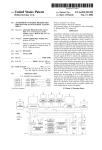
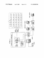
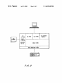
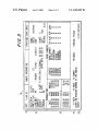
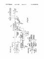
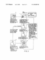
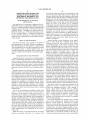
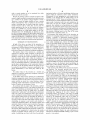
US006920209B1
(12) United States Patent
(10) Patent N0.:
(45) Date of Patent:
Gainsboro
(54) COMPUTER-BASED METHOD AND
APPARATUS FOR CONTROLLING,
MONITORING, RECORDING AND
Bahl, L. “A Maximum Likelihood Approach to Continuous
Speech Recovery”, Readings in Speech Recognition Ed. A.
Waibel and K. Lee, Morgan Kaufmann Publishers, pp
308—319, IEEE 1983.
(75) Inventor: Jay L. Gainsboro, Framingham, MA
Batten, A. “Personal Communications Service and the Intel
(Us)
ligent Network”, British Telecommunications Engineering,
vol. 9, pp 85—91 Aug. 1990.
(73) Assignee: T-NetiX, Inc., Carrollton, TX (US)
Notice:
Jul. 19,2005
OTHER PUBLICATIONS
REPORTING TELEPHONE ACCESS
(*)
US 6,920,209 B1
Lee, K. “Large—Vocabulary Speaker—Independent Continu
ous Speech Recognition Using HMM”, Carnegie Mellon
University Department of Electrical and Computer Engi
neering, CMU—CS—88—148 Apr. 1988.
System 20, Nov. 1992.
Subject to any disclaimer, the term of this
patent is extended or adjusted under 35
U.S.C. 154(b) by 136 days.
(21) Appl. N0.: 10/327,248
Telematic “ConQuest III Intimate Telephone System” Nov.
(22) Filed:
LaZerVoice, Digital Recording System Inmate Services,
1992.
Dec. 19, 2002
1997—98 Schlumberger Technologies, Inc./LaZerVoice ,
STIL V0222 LaZerVoice User’s Manual—Version 2.22.
LaZerPhone User Reference Manual.
Related US. Application Data
(63)
LaZerPhone, Inmate Telephone System, Users Manual, 1998
Schlumberger Technologies, Inc./Global Tel*Link, LaZer
Continuation of application No. 08/904,784, ?led on Aug. 1,
1997, now Pat. No. 6,560,323, which is a continuation of
application No. 08/510,327, ?led on Aug. 2, 1995, now Pat.
No. 5,655,013, which is a continuation of application No.
08/229,517, ?led on Apr. 19, 1994, now abandoned.
(51)
Phone User’s Manual—Version 1.0.
LaZerPhone, Powerful Performance Uncompromising Stan
dards, 1998.
LaZerPhone Technical Manual, System Overview.
Int. Cl.7 ............................................... .. H04M 3/00
(52)
.. 379/188; 379/199; 379/249
(58)
Field of Search ......................... .. 379/91.01, 91.62,
Primary Examiner—Roland G. Foster
(74) Attorney, Agent, or Firm—Fenwick & West LLP
379/112, 143, 144, 145, 101, 108, 189,
196, 198, 199, 200, 34, 35, 207.01, 207.02,
207.11, 211.01, 211.02, 216.02, 211.03,
114.01, 114.41, 112.01, 144.01, 85.16,
(57)
A method and apparatus for managing institutional tele
188, 249
(56)
phone activity utiliZes a computer control unit to control a
trunk management unit, which connects institutional tele
References Cited
phones to outside telephone lines. The computer control unit
contains a database for storing the calling privileges and
restrictions of institutional users and for recording calling
U.S. PATENT DOCUMENTS
3,851,121 A
4,001,513 A
4,002,848
4,054,756
4,188,508
4,310,726
4,405,833
A
A
A
A
A
11/1974 Marvin
transactions made by the users. The computer control unit
1/1977 Naylor
1/1977
10/1977
2/1980
1/1982
9/1983
ABSTRACT
implements a prospective call screening feature whereby
Stein
Comella et al.
Rogers et al.
Asmuth
Cave et al.
outside recipients of undesired calls from the institution may
enter a code that directs the computer control unit to prohibit
similar calls in the future.
15 Claims, 5 Drawing Sheets
(Continued)
EQUIPMENT LOCATED IN TELEPHONE ROOM
INNAIE
IELEPHDNES
INHAIE
TELEPNUNES
US 6,920,209 B1
Page2
US. PATENT DOCUMENTS
4,518,825
4,559,416
4,602,129
4,696,031
4,726,057
4,782,516
4,794,642
4,799,255
4,815,120
4,885,765
4,896,348
4,899,375
4,901,341
4,922,519
4,922,520
4,924,488
4,933,966
4,933,967
4,935,956
4,937,862
4,993,068
5,023,869
5,023,906
5,033,088
5,054,059
5,063,593
5,109,405
5,131,024
5,150,357
5,163,083
5,187,740
5,200,995
5,210,789
5,222,120
5,229,764
5,274,698
5,276,731
5,305,312
5,309,505
5,311,589
5,319,702
5/1985
12/1985
7/1986
9/1987
2/1988
11/1988
12/1988
1/1989
3/1989
12/1989
1/1990
2/1990
2/1990
5/1990
5/1990
5/1990
6/1990
6/1990
6/1990
6/1990
2/1991
6/1991
6/1991
7/1991
10/1991
11/1991
4/1992
7/1992
9/1992
11/1992
2/1993
4/1993
5/1993
6/1993
7/1993
12/1993
1/1994
4/1994
5/1994
5/1994
6/1994
Brikerhoff et al.
Theis et al.
Matthews et al.
Freudberg et al.
Doerry et al.
Maybach et al.
ArbabZadah et al.
Billinger et al.
Kosich et al.
Shirakawa
Grantland et al.
Bauer et al.
Carter et al.
Daudelin
Bernard et al.
Kosich
Hird et al.
Lo et al.
HellWarth et al.
Kosich
Poisenka et al.
Grover et al.
Novas
Shipman
Stern et al.
Kwon
Morganstein
Pugh et al.
Hopner et al.
Dowden et al.
SWaim et al.
Gaukel et al.
Jeffus et al.
McLeod et al.
Matchett et al.
Jang
Arbel et al.
Fornek et al.
SZlam et al.
Bennett et al.
Kitchin et al.
5,325,427
5,327,489
5,329,578
5,345,595
5,351,287
5,355,403
5,375,161
5,442,696
5,452,347
5,465,293
5,471,519
5,483,582
5,483,593
5,535,261
5,539,812
5,566,229
5,583,934
5,606,604
5,617,471
5,627,887
5,651,056
5,655,013
5,722,418
5,724,404
5,745,553
5,796,811
5,799,068
5,805,685
5,809,125
5,844,978
5,883,945
5,926,533
5,943,403
5,960,064
6,052,454
6,072,860
6,141,406
RE37,073
6,188,751
6,560,323
6,611,583
E
6/1994
7/1994
7/1994
9/1994
9/1994
10/1994
12/1994
8/1995
9/1995
11/1995
11/1995
1/1996
1/1996
7/1996
7/1996
10/1996
12/1996
2/1997
4/1997
5/1997
7/1997
8/1997
3/1998
3/1998
4/1998
8/1998
8/1998
9/1998
9/1998
12/1998
3/1999
7/1999
8/1999
9/1999
4/2000
6/2000
10/2000
2/2001
2/2001
5/2003
8/2003
Dighe
Anderson et al.
Brennan et al.
Johnson et al.
Bhattacharyya et al.
Richardson, Jr. et al.
Fuller et al.
Lindberg et al.
Iglehart et al.
Chiller et al.
Howe et al.
Pugh et al.
Gupta et al.
Brown et al.
Kitchin et al.
Hou et al.
Zhou
Rosenblatt
Rogers et al.
Freedman
Eting et al.
Gainsboro
Bro
Garcia et al.
Mirville et al.
McFarlen
Kikinis et al.
McFarlen
Gammino
Reuss et al.
Richardson et al.
Gainsboro
Richardson, Jr. et al.
Foladare et al.
Kek et al.
Kek et al.
Johnson
Hammond
Scherer
Gainsboro
Gainsboro
U.S. Patent
Jul. 19,2005
Sheet 1 0f 5
_
n
u
w
MW
MN
Wm
%
%ANw“nu.“"
zs?oéz$325
_\| Mm
"$2252
2%%
MW
Mw
U
_
l12H6Q\wE}.;
,120%
x
1,
é
n,
w
%
@
MW
_l . 582915
m
“MN
MN.
W.
W
MW
nw
Mwuz?waés
"
n
_
,
.
_
n
‘(?aw
zmz??_Ea:
a
_
1I|. 25%.
US 6,920,209 B1
U.S. Patent
Jul. 19, 2005
OT
sow“
THU
F IRMWARE
Sheet 2 0f 5
SOL MENU
S01. FORMS
ORACLE
INTERFACE
*éQQLTTFQOMLE
'ORACLE DBMS
UNIX OPERATING SYSTEM
F/G.2
US 6,920,209 B1
50L REPORT
WRITER
U.S. Patent
Jul. 19, 2005
Sheet 5 of5
US 6,920,209 B1
TRUNK
MANAGEMENT UNIT
ATE DESTTNATION
ALERT
NUMBER
XJANXX (XXXTXXXXXXX
|NMATE(CALLERTGOES OFF
ENFORCER°SYSTEM PERFORMS ITS
HOOK AND ENTERS DIGITS
STANDARD INMATE AccouIIT
REPRESENTING A
PRE-APPROVED DESTINATION
PARAMETER cIIEcIIs AND IF
VALIDATED coIIREcTS CALL TO
PHONE NUMBER a PIN
PRE- APPROVED ‘DESTINATION PARTY
THE lGlT ARETRRIIsIIITTEn"
jzlvm RoII LINES AND RECEIVED‘
(IF CA U I sroRw AR OED)‘
IBWYHEUE
0SRYCSETREIISAISIITERRREITEMs,l
lTRIE DIGITS AS AN ACTION m» I
|1)|DENTIFY THE oRIcImL
l
APPROVED PHONE NUMBERIN ‘
0
DES T INATT oN PARTY FRWARDS
'
DESTINATION PARTHAT
CALLING 0R CONFERENCE
REEEMEUCUER! WWW I THAT PHONE NUMBER WHICH 1
THE CALL usIIIc S-WAY
PR -AP 0
PH
CALLING To ANOTHER
I TINTCANMTAETEEAEECNNUTIAUE I
) lzIAssIcII AN ALERT CODE To
55 I THE SYSTEM IIIL
DESTINATION NUMBER
RECOGNIZE AS
me A
I
I PHONE NUMBER IIIIIcR-
|
IT’TEHETBTNIHMTW
II
I THE INHATE ISBLOCKEDFROM I
MAKING FURTHER CALL
I ATTEMPTS
I
THE PARTY DETERMINES THAT
THEY 00 NOT WANT To BE CAUID I
BI THAT PIN NUMBER AGAIN,
T
NEW PARTY RECEIVES CALL
AND DETERNTNES THAT THEY
WANT TO
THE PARTY ENTER GOT U OIOIT
CODE INTO TELEPHONE KEY PAD,
THEN HANGS UP
TTDISOONTINUE THE CURRENT
L
CALL. AND/OR
2T PREVENT CALLER FROM
CALUNG THEM AGAIN
,
TAKEN BY A CALLED
I_ _ __ _ __ _ __ _ _|
5
US 6,920,209 B1
1
2
COMPUTER-BASED METHOD AND
environment, it does not Work Well in a penal institution. The
reason is that inmates shoW little concern for phone bills
they can’t afford to pay. Thus, the institution is often forced
APPARATUS FOR CONTROLLING,
MONITORING, RECORDING AND
to absorb the costs of phone calls by its delinquent inmates.
Moreover, the fact that account balances are only computed
periodically—i.e., every month, Week, or even every day—
permits the inmate to accrue large, uncollectible phone bills
REPORTING TELEPHONE ACCESS
CROSS-REFERENCE TO RELATED
APPLICATIONS
before his access to the phones can be terminated.
This application is a continuation of application Ser. No.
08/904,784, entitled “Computer-Based Method and Appa
ratus for Controlling, Monitoring, Recording and Reporting
Telephone Access,” ?led Aug. 1, 1997 now US. Pat. No.
6,560,323, Which is a continuation of application Ser. No.
08/510,327, ?led Aug. 2, 1995, Which Was issued as US.
Pat. No. 5,655,013, Which is a continuation of application
Ser. No. 08/229,517, ?led Apr. 19, 1994, Which Was aban
doned. The above applications are incorporated by reference
10
15
in their entirety.
20
Another problem in penal institutions is the inmates’
desire to make threatening or harassing phone calls to
Witnesses, prosecutors, police officers, parole of?cers,
telecommunications and penal institution management.
psychologists, judges, and the relatives and family of such
More particularly, the invention relates to a computer-based
method and apparatus for controlling, monitoring, recording
and reporting access to outside telephone lines in a
controlled, institutional environment, such as a prison, mili
still provides the inmates With relatively unlimited access to
the outside World, leaving open numerous opportunities for
fraudulent and criminal activity, as explained beloW.
Therefore, in a penal environment, it is highly desirable to
regulate phone access on an individual, pay-in-advance
basis, and to immediately and automatically terminate an
individual’s phone access When his/her paid-up account
reaches a Zero balance.
FIELD OF THE INVENTION
The present invention relates generally to the ?elds of
Traditionally, penal institutions have addressed this problem
by restricting inmates to collect calls only. This, hoWever,
25
tary base, hospital, school, business or government organi
persons. Limiting the inmates’ access to collect calls only
does not effectively address this problem, since an inmate
can easily identify himself (to an operator) as someone from
Whom the recipient Would likely accept a collect call.
Rather, one should, at a minimum, provide a means that
Zation.
permits a potential call recipient to identify the caller as an
inmate before accepting the call, Whether that call is placed
BACKGROUND OF THE INVENTION
Generally, the need to control access to outside telephone
lines in an institutional environment is Well recogniZed. In
order to prevent individuals from incurring large, unac
30
countable telephone costs Which the institution ultimately
bears, one must either restrict access to outside telephone 35
lines or institute accounting controls Whereby the costs of
unauthoriZed calls can be billed to the responsible individu
als.
placed from a correctional facility and that, if the recipient
Wishes not to receive the call, he/she should hang up before
the call is connected. This approach mitigates, but does not
fully solve, the harassment problem. In particular, it is still
possible for an inmate to repetitively call an outside party;
even if the recipient hangs up after hearing the pre-recorded
message, the harassing effect of receiving repetitive calls
Telephone systems in correctional environments require
additional security considerations. Without appropriate con
on a prepaid or collect basis. Conventionally, this is done by
initially placing the inmate on hold and playing a pre
recorded message telling the recipient that a call has been
trols on telephone access, inmates have been knoWn to use
from inside the correctional institution remains. Therefore, it
Would be highly desirable to provide an institutional tele
the telephones to harass outside parties (such as Witnesses
phone system that automatically prohibits inmates from
Who testi?ed against them, attorneys Who prosecuted their
case, employees of the courts, etc.), to perpetrate fraudulent
schemes, and to participate in criminal conspiracies (such as
arranging the smuggling of contraband into the prison,
directing an outside criminal enterprise, plotting escape
attempts or credit card fraud). Therefore, it is critically
important for correctional management officials to carefully
attempting to call certain outside persons. Moreover, it
Would also be highly desirable to provide a method and
apparatus for alloWing a recipient of an undesired call from
an inmate to easily and automatically prohibit all future calls
from that particular inmate, or from all inmates generally.
40
45
Still another concern in correctional institutions is the
regulation of access to telephone systems. For various
security and management reasons, it often desirable to
restrict a given inmate’s telephone access to particular
plan, control, monitor and record inmate access to outside
telephone lines.
One of the most fundamental problems—Which eXists
both in correctional and other business-oriented
institutions—is cost control. To achieve cost control, it is
critical that there be individual accountability for each call
that incurs a charge to the institution. Such accountability is
phones, calling times, and to limit the length of calls,
number of calls, and number of calls to the same number.
55
Also, to enhance security and discipline, it should be pos
sible to instantaneously revoke an inmate’s calling
privileges, or to otherWise modify the eXtent of a particular
typically achieved through use of personal identi?cation
inmate’s calling privileges.
numbers (“pins”). Before making a call from an institution
telephone, an individual must enter his PIN. The telephone
service provider is then able to deliver to the institution an
end-of-the-month telephone bill Which lists, in addition to
and/or record outgoing calls. Inmate-to-attorney calls,
Correctional institutions also typically Wish to monitor
60
Moreover, certain inmates—those Who represent particular
the cost of each call, the PIN or name of the individual Who
made the call. From this information, the institution can then
collect reimbursement from individuals for the costs of
certain calls.
While this system of end-of-the-month call accounting
functions reasonably effectively in a business like
hoWever, cannot legally be monitored or recorded.
security risks—deserve live monitoring, as opposed to mere
recording. Thus, it Would be highly desirable to have a
65
system Which automatically initiates the appropriate moni
toring and/or recording depending upon the identity of the
inmate placing a call and the recipient of the call (i.e.,
attorney or non-attorney). LikeWise, it may be desirable that
US 6,920,209 B1
3
4
calls to certain numbers are to be monitored live, While
institutional caller or, if desired, prohibiting calls from any
person Within the institution and/or related institutions.
others need only be recorded.
Because the message content of inmate-to-attorney calls
cannot be legally recorded or monitored, such calls can serve
Alternatively, if voice prompting or voice menus are not
available or not desired, then the public-at-large can be
as a conduit for the inmate’s illegal telephone activity.
Therefore, it Would be highly desirable to have a system
Which could passively—that is, Without in any Way moni
upon receipt of undesired calls from such institutions, the
informed that the “GOTU” feature is available in their area,
and With respect to certain institutions in their area, and then,
called party can enter the “GOTU” touchtone or keypad
toring or recording What is actually being said—monitor
inmate-to-attorney calls to ensure that: (1) the only tWo
people speaking on the line are the inmate and attorney,
10
and/or (2) no DTMF tones, rapid line impedance changes,
off-hook conditions or voltage spikes appear on the line.
Techniques for voice identi?cation are knoWn—i.e. US.
Pat. No. 4,993,068, entitled UNFORGEABLE PERSONAL
IDENTIFICATION SYSTEM and US. Pat. No. 5,150,357,
entitled INTEGRATED COMMUNICATIONS SYSTEM,
called party’s telephone number, blocking during particular
15
previously used in penal telecommunications applications.
SUMMARY OF THE INVENTION
In light of the above, one object of the invention is a
method of managing telephone activity in an institutional
environment to achieve improved security and reduced cost.
Another object of the invention is a system adapted to
25
Still another object of the invention is a method and
apparatus for alloWing outside recipients of calls from an
institution to decide, in advance of connecting the call,
Whether to accept the given call and Whether to block calls
the inmate, or that the number called by the inmate can not
be reached for any number of reasons, as established by the
call—plays an announcement to the called party identifying
the institution and caller, along With the options available to
the called party. In response, the called party may enter the
announced DTMF tone sequence (preferably GOTU), Which
modi?es a record in the database, thereby prohibiting the
35
prison administration, or the actual party called by the
inmate.
Yet another object of the invention is a method and
apparatus for passively monitoring a telephone connection
40
to detect security breaches.
A still further object of the invention is an institutional
telephone management system Wherein the parameters that
control the operation of the system as Well as the records of
includes: a plurality of institutional telephones located
Within the institution; a trunk management unit (TMU) for
selectively connecting the institutional telephones to one or
more outside telephone lines, Wherein the TMU includes
means for decoding DTMF tones generated by the institu
tional telephones or received from the outside telephone
lines; and a computer control unit (CCU), coupled to the
TMU, for controlling the connection of the institutional
telephones to the outside telephone lines based upon DTMF
tone(s) received from the outside telephone lines. Adatabase
associated With the CCU contains information regarding the
calling privileges of each person Within the institution. In a
preferred embodiment, the TMU—prior to connecting the
from that person and/or others Within the institution or
related institutions in the future, and optionally, Whether to
indicate to the inmate that the call has been either tempo
rarily or permanently blocked by a particular party, includ
ing the prison administration, or the actual party called by
time periods, blocking based on the class of the crime
associated With a particular inmate, etc.
In accordance With another aspect of the invention, an
apparatus for managing telephone activity in an institution
both incorporated herein by reference—but have not been
perform such improved institutional telephone management.
sequence. Any multitude of call prohibitions can be estab
lished as to any particular inmate by the prison administra
tion or the called party, including total blocking based on the
45
system activity are stored in a central database, thereby
caller (and/or other similarly situated prospective callers)
from calling the called party in the future.
Other features of the TMU provide security and monitor
ing functions. The invention provides three levels of
monitoring, any or all of Which may be active for any given
call. The ?rst level is “live” call (voice) monitoring, Where
the prison of?cials actively listen to a live call. The second
level is call recording. The TMU can be programmed to
enable associated recording equipment to record telephone
calls. The third level is “passive” line monitoring, Where the
TMU detects, for example, DTMF tones, off-hook
conditions, voltage spikes and/or sudden line impedance
permitting simple customiZation of system operation, gen
changes, in order to thWart attempts at unauthoriZed three
eration of reports and monitoring of status.
Way calling, call conferencing, call transferring, call for
In accordance With one aspect of the invention, a method
Warding or re-dialing via various alternate common carriers,
of managing telephone activity in an institution includes the
many of Whom noW offer “1-800” or local telephone number
steps of: (1) identifying an institutional caller (the “calling
(e.g., “950”) access numbers. Also, care is taken to avoid
party”) Who Wishes to place an outside call to an outside
disrupting calls that do not represent security breaches, by
preventing false triggering of the above “passive” line
monitoring features. For eXample, With respect to DTMF
recipient (the “called party”); (2) blocking the institutional
caller and—While the institutional caller’s line (earpiece
and/or mouthpiece) remains blocked—(a) calling said out
55
tone blocking, the TMU Will look for any additional digits
side recipient (called party), (b) providing the identity of
entered by an institutional caller, such as an inmate, to
said institutional caller to said outside recipient and (c)
receiving a control code from said outside recipient; and (3)
determining, in response to said control code, Whether to
prevent the inmate from redialing to other telephone num
bers that may not be authoriZed. HoWever, to prevent
“talkoff”, Whereby the normal telephone conversation can
falsely trigger a disconnect signal (because the TMU may
connect the institutional caller to the outside recipient, and
optionally, Whether to indicate any of a plurality of messages
to the calling party, e.g., an inmate. The control code
interpret the conversation as DTMF dialing), the TMU can
be set to look at the number of digits dialed Within a
speci?ed time period (e.g., siX (6) digits Within a ?fteen (15)
preferably comprises a series of DTMF tones, for eXample
the sequence 4688, Which spells the pneumonic “GOTU”. In
response to the recognition of a control code, the outside
recipient is provided With the option (via a voice prompt
menu) of prohibiting any future calls from the particular
65
second time period, or any variation of the tWo parameters)
and thereby, determine Whether the audio information is
indicative of unauthoriZed DTMF redialing or just a normal
speech or voice pattern.
US 6,920,209 B1
5
6
In accordance With the preferred embodiment of the
invention, all calls are passively monitored and all calls that
can be legally recorded—i.e., all but inmate-to-attorney
calls—are recorded. At any time, prison officials can selec
tively invoke live monitoring to listen in on any call in
progress, except an inmate-to-attorney call. System alarms,
Which trigger any time a particular inmate places a call or
should not be vieWed as limiting, since the invention is also
applicable in other institutional settings such as military
bases, schools, mental institutions and business organiZa
tions.
Referring noW to FIG. 1, a call management system
manages calls from a plurality of inmate telephones 1. A
TMU 2 controls the connection of individual inmate tele
calls a certain person, alloW officials to determine When live
phones (for example 1a) to outside telephone lines 8, and
call monitoring is appropriate. Likewise, the telephone sys
electronically monitors connected calls. A TMU 2 can
tem of the present. invention can be programmed to default
in any manner. For example, the system can be set to place
only those telephone calls that are among a preapproved list
of telephone numbers. Conversely, the system can be set to
place all telephone calls except those that are among a list of
optionally contain (and/or be connected to external) voice
messaging or voice synthesis equipment, to facilitate fea
tures such as over-the-phone voice prompting, voice mail, or
any voice activated, responsive or interactive telephone
restricted telephone numbers. Optionally, the telephone sys
tem of the present invention can include speed-dialing,
Whereby upon entering a PIN, for example, an inmate can
enter “11” folloWed by the “#” key. In that case, the prison
administrator may have established that “11” is the speed
dialing sequence for that inmate’s mother. Of course, the
system could be con?gured so that the inmates themselves
15
Additionally, the inmate could ascertain hoW much any prior
telephone call has cost, and further, could dial an intended
telephone call, and ascertain hoW much that call Will cost for
the ?rst time period (e.g., the ?rst minute), or, ?nd out hoW
can program the telephone system With speed-dialing digits,
hoWever, a principal objective of speed-dialing is to save
time at the telephone, thus making the telephones available
to the largest number of inmates in the shortest possible time
period.
many minutes the inmate can be connected to that telephone
25
In addition, the invention may include biometric voice
veri?cation features. The TMU, for example, may digitiZe a
sample of the caller’s voice. The CCU then compares the
digitiZed sample With a stored voice print, to verify the
identity of the caller. Such biometric monitoring may also be
used in a passive call monitoring mode, Wherein periodic
samples of the caller’s voice are provided to the CCU—and
during a call connection, inmate funds become nearly
exhausted, a Warning tone could inform the inmate of that
condition, so that the inmate can terminate the conversation,
and take appropriate steps to replenish his/her account. Such
that no unauthoriZed callers are participating in a call, and to
ensure that inmates are not sharing or selling relatively
35
inmate account to other inmates that are subject to more
Warning tones could be made possible by a real time call cost
monitoring system, that compares inmate call costs and
inmate account balances While each call is in progress.
A serial interface card 4 digitally interfaces TMU 2 to: a
CCU 3, one or more administrative terminals 5a—b and, via
data modems 6a—b, to a remote terminal 7. Of course,
limited calling privileges. The use of biometric voice veri
?cation (or “voice prints”) can prevent PIN abuse in general.
For example, if a particular inmate With restricted calling
privileges, or no available funds, attempted to force (e.g., by
number, given the cost of that call and the amount remaining
in the inmate’s account, all prior to actually completing the
call and becoming obligated to pay for it. Obviously, for
debit-based systems, inmate calls Will not be placed in the
event that suf?cient funds are not available. Further, if
checked against a list of authoriZed voice prints—to ensure
liberal calling privileges associated With a particular PIN or
feature. For example, an inmate could enter his/her PIN into
a telephone 1 keypad, and then, access his/her account. In
turn, voice equipment associated With or contained Within
the TMU could inform the inmate of the exact balance
available in his/her account for future telephone calls.
40
remote terminals 7, administrative terminals 5 and CCUs 3
can be connected via so-called dedicated data/telephone line
threatening physical attack) another inmate With relatively
non-restricted calling privileges (or available funds) to turn
services, obviating the need for actual modems 6.
TMU 2 communicates bi-directionally With CCU 3. In
over his PIN, biometric voice veri?cation Would obviate this
problem, as the voice Would be used to validate entry into
one direction, CCU 3 directs TMU 2 to connect, record,
passively monitor and terminate calls, and to doWnload
any inmate account.
45
BRIEF DESCRIPTION OF THE DRAWINGS
real-time status—i.e. off-hook, DTMF tones, voltage spikes
and rapid impedance changes—of institutional and outside
telephone lines. In addition, TMU 2 can provide digitiZed
The detailed description beloW describes the preferred
embodiments of the invention and is intended to be read in
conjunction With the set of draWings, in Which:
FIG. 1 is a block diagram shoWing the major components
of a preferred apparatus, including a plurality of institutional
telephones, a computer control unit (CCU) and a trunk
voice samples to CCU 3 in order to record messages (such
as the inmate’s name) and to support biometric voice
veri?cation or monitoring functions. Optionally, TMU 2 (or
other comparable apparatus) could be con?gured to provide
digitiZed voice samples to, for example, CCU 3, for each call
management unit (TMU);
FIG. 2 is a block diagram shoWing the softWare and
?rmWare architecture of the apparatus;
and/or play prerecorded messages to an inmate or outside
call recipient. In the other direction, TMU 2 monitors the
55
made, Whereby such samples are suf?cient in length to
provide veri?cation that the inmate indeed participated in a
FIG. 4 is a block diagram of a TMU; and
conversation With a particular called party on a particular
date and at a particular time. Because prison administrators
may not Wish to charge inmates (or in the case of collect
FIG. 5 is a How diagram depicting the operation of the call
calls, called parties) for certain calls (for example, calls the
FIG. 3 is an exemplary screen shoWing an institutional
user’s calling privileges and activity;
administrator deems incomplete), it is critical that adminis
trators have the ability to verify actual telephone commu
quali?cation process, including the invention’s prospective
call screening (or “GOTU”) feature.
DETAILED DESCRIPTION OF THE
PREFERRED EMBODIMENTS
The preferred embodiment(s) Will be described With ref
erence to prison based call management. This, hoWever,
nications. Incomplete telephone calls may include, for
example, busy signals, calls that do not “go through”, calls
65
that are not ansWered (as distinct from calls that reach
ansWering machines, Which may be deemedzcomplete), etc.
Thus, if an inmate or a called party subsequently claims that
US 6,920,209 B1
7
8
a particular telephone communication never occurred (e.g.,
a busy signal Was reached, the called party never ansWered,
includes circuitry to selectively connect inmate phones With
outside lines, to selectively monitor and record the
connection, and to generate appropriate voice instructions or
prompts to the inmate and/or the outside call recipient.
or no voices Were spoken at all), the prison administer can
retrieve the voice veri?cation record to evaluate Whether,
e.g., a credit is due, telephone system repair is required, or
As depicted in FIG. 4, a channel of TMU 2 connects to an
inmate telephone 1 at a station input line 40. A record
blocking circuit 41 connects station input line 40 to record
Whether claims that certain calls Were incomplete are false.
Referring noW to FIG. 2, CCU 3 is preferably a “486”
ing equipment (not depicted) via line 41a (Which line can
personal computer or larger “super-mini” type computer
also be used for “live” call monitoring). CCU 3 automati
cally controls an attorney relay 41b and, in the case of an
inmate-to-attorney call, sWitches line 41a to a tone generator
con?gured to operate under a suitable operating system,
such as UNIXTM System V. Of course, any number of
operating systems Will be suitable for the purpose of the
present invention. In addition to the operating system, a
database management system (DBMS), such as
ORACLETM, Which includes a structured query language
(SQL) interface, is used to store system con?guration and
15
status information. An SQL forms generator provides access
to the stored con?guration and status information. An SQL
menu program alloWs users to easily navigate the database
system. An SQL report Writer is used to generate reports of
calling activity or other system usage.
TMU ?rmWare controls the operation of TMU 2. TMU
interface softWare in CCU 3 is con?gured to manage com
munication betWeen TMU 2 and CCU 3. ORACLE interface
softWare provides a simple, menu based interface to ?eld
users such as correctional of?cers and management of?cials.
41c, thereby blocking improper attempts to record or moni
tor inmate-to-attorney calls.
A split relay 42 sWitches the inmate telephone betWeen a
local line 42a and an outside line 42b. Initially (i.e. before
the inmate initiates a call), split relay 42 connects station
input line 40 (via local line 42a) to a monitor circuit 43,
Which monitors the inmate’s telephone. Monitor circuit 43
supplies a battery feed to the inmate’s telephone, and
performs pulse digit recognition and current detection as
Well. Adial tone generator 43a (Which is preferably common
to all channels of the TMU) supplies a dial tone to the
inmate’s phone. A relay 44a sWitches a DTMF receiver 44
to decode tones on the local line 42a or the outside line 42b.
A voice-out-station line 45a supplies voice messages to the
25
Real-time control softWare manages the real-time activity of
the system and responds to communications from TMU 2
inmate’s telephone. CCU 3 controls the decoder portion of
an integrated coder/decoder (CODEC) circuit to generate the
messages fed to line 45a. (The decoder portion of a second
CODEC also drives a voice out central office line 45c to play
and user inputs from CCU 3 or terminals 5a—b and 7.
From an administrator/user perspective, the CCU soft
messages to outside line 42b.) A central of?ce voice input
line 47b connects to the coder portion of the CODEC circuit
Ware supports the folloWing general functions:
(1) establishment and con?guration of individual inmate
data and monetary accounts;
to support message recording, voice monitoring and/or
veri?cation functions. Optionally, voice-in-station 42c is
used to record the name of an inmate. Also optional, ansWer
board line 47g is used to detect called party ansWer
conditions, by detecting the presence or loss of call progress
(2) checking of inmate debit (i.e. paid-in-advance)
accounts;
(3) setting of global (i.e. institution Wide) and individual
35
A hold circuit 46 is used to interact With the outside caller
(4) real-time monitoring of inmate telephone calls and
alerts (based on call content, security breaches, etc.),
along With the ability to cut off inmate calls individu
tones (e.g., ringing, busy, special-information-tones (SITs),
etc.).
restrictions on telephone access;
during the call quali?cation process, during Which the sta
tion input line 40 is sWitched to local line 42a. A hold relay
40
ally or globally;
(5) storing and reporting of detailed inmate call details
46a selectively connects hold circuit 46 to outside line 42b.
A DTMF generator 46c (preferably common to all channels
of the TMU) is controlled by CCU 3 to, for example, place
and account information; and
an outside call to a requested number. Hold circuit 46
interfaces With DTMF receiver 44 to detect tones generated
(6) storing and reporting of telephone usage data.
easy access to various information regarding an inmate’s
by the outside caller during the call quali?cation process.
The hold circuit 46 (With its associated relay 46a) can also
debit account, calling privileges and calling activity. The
pass audio information directly to the monitor circuit 43 as
FIG. 3 form includes a title segment 31, Which displays the
current date, title of the form and form code. BeloW the title
desired via audio feed through line 46b. The hold circuit 46
can also be used for dial-pulse dialing to the central of?ce.
Line current detector 47a (preferably implemented using an
Referring noW to FIG. 3, an exemplary form 30 provides
45
segment is a header segment 32, Which typically displays
such information as the inmate’s name, registration number,
opto-isolator), ring detector 476, and tip/ground detector 47d
preferred language selection, prisoner account code (“PAC”,
monitor the status of outside line 42b. Ground start relay 47f
connects a ground start circuit to the ring Wire of outside
lines 48a and 48b, to start “ground-start” type lines. A line
relay 48 sWitches outside line 42b betWeen a central office
main line 48a and a central of?ce auXiliary line 48b.
In addition to the channel circuitry described above, TMU
2 is controlled by a microprocessor 49a, Which interfaces
With a Watchdog timer 49b and With a memory 49c, channel
I/O 49d, miscellaneous 1/0 496 and dual serial ports 49f via
data, or so-called “glue” logic 49g. TMU 2 also includes a
jack tester circuit 49h and connectors 49i and 49j to ansWer
and voice boards, respectively. The voice board contains a
or PIN), certain calling privilege information and account
balance. BeloW the header are a plurality of data blocks 33,
Which shoW the inmate’s transactions (both accounting
transactions and phone calls) as Well as his/her calling
privileges and restrictions—i.e., numbers the inmate is
alloWed to call, the inmate’s attorney’s number, numbers the
inmate is prohibited from calling, and numbers Which
55
should trigger an alert on the system terminals When a call
is attempted. The system alloWs the user to scroll through the
data blocks in order to bring any particular transaction or
restriction into vieW. A help line 34 lists the commands
plurality of integrated CODECs (preferably tWo per TMU
available to the user. A bottom positioned status line 35
completes the form.
Referring noW to FIG. 4, a block diagram of one channel
of a multichannel TMU 2 is shoWn. Generally, TMU 2
65
channel) as Well as circuitry needed to permit CCU control
of the CODECs, including I/O circuitry and voice data
buffers.
US 6,920,209 B1
10
Referring noW to FIG. 5, the method of connecting an
inmate call can noW be discussed. TMU 2 continuously
destination caller as to Whether he/she Would like to prohibit
all future calls from inmates Within the particular prison or
any associated prison employing the same or similar call
monitors the inmate telephones 1. To place a call, in step 50,
order established by the facility): (1) his/her personal iden
management technology. Also, the destination caller may be
prompted by any number of other alternatives. For example,
ti?cation number (PIN); and (2) the number to be called.
TMU 2 forWards both numbers to CCU 3, Which, in step 51,
queries the inmate’s account to check Whether:
the called party may be instructed to press “1” to reject all
future calls from that inmate; press “2” to reject all future
calls from that prison; press “3” to generate a busy signal to
(1) there are suf?cient funds in the inmate’s debit account
to make the call (unless the call is a collect call);
the inmate—in that event, the calling party (inmate) Would
an inmate picks up a phone and enters tWo numbers (in any
10
(2) the particular inmate is alloWed to: (a) use the par
“5” to enter certain times of the day or dates to block calls
from this inmate in the future; and so forth. Also, the called
ticular telephone extension; (b) place calls at the given
time-of-day; or (c) has exceeded a maximum number of
calls or calling minutes Within a given period of time;
and
(3) based upon the number to be called, Whether the
number is approved or prohibited, Whether the number
party can be given the phone number of the prison telephone
system service bureau, so that previously issued instructions
15
to block calls (from particular inmates or facilities) can be
erased. In any event, the called party’s response is trans
mitted to CCU 2. If the response represents a desire to
to be called corresponds to the inmate’s attorney (in
prohibit calls from all inmates, CCU 2 records a global
calling restriction in the database associated With the par
ticular institution, and if appropriate, transmits the restric
Which case, the conversation Will not be recorded or
“live” monitored), and Whether there are any time-of
day or call frequency or other restrictions on the
number to be called.
If the call is rejected on the basis of (1)—(3) above, CCU
3 directs TMU 2 to play a message to the inmate (in the
inmate’s preferred language, determined by his/her PIN and
hear a busy signal in his/her earpiece; press “4” to state that
“The number you have dialed has been disconnected”; press
tion to other related institutions via a computer netWork.
Step 55 handles forWarded calls in a similar manner. Thus,
the GOTU feature serves to blocks calls from inmates, based
25
established When the prisoner ?rst enters the facility)
explaining the reason that the call has been rejected. Assum
ing that the requested call has passed these initial screening
on the number that the inmate has dialed—either by entering
that number to a list of restricted numbers, or by deleting that
number from a list of preapproved numbers, depending upon
hoW the administrator has con?gured the inmate telephone
system. In any event, the inmate Will lose access to that
telephone number in the future, based on the fact that the
tests, CCU 2 directs TMU 2 to call the destination party.
Until completion of step 53 or 55, the inmate’s earpiece and
mouthpiece remain blocked (With respect to the called
called party has entered the GOTU (“4688”) keypad
party), thereby eliminating the inmate’s opportunity to inter
?gured to control the costs of collect calls accepted by the
destination party. In that event, the destination party could,
sequence. Optionally, the GOTU feature can also be con
ject offensive or harassing remarks. In step 52, the destina
tion or called party receives the call and hears a prerecorded
message Which identi?es the institution, caller and gives
for example, in response to a voice prompt, enter a dollar
35
instructions as to hoW the called party may elect to receive
the call and hoW the party may block future calls, if desired.
The message may, for example, state:
“You are receiving a call from [name of inmate] at the
[name of institution]. If you Wish to be connected,
please press [a certain digit] noW and the call Will be
connected in [number] seconds. If you Wish to prohibit
future calls from [name of inmate] or anyone at [name
40
possibility of telephone harassment. Advantageously, the
GOTU feature also ?nds use in a standard (i.e. non
of institution], please press G-O-T-U or 4688 . . .”
Advantageously, the pronunciation of inmate’s name is
value limit corresponding to the maximum permissible cost
of the current inmate call. As Well, any series of Warning
tones could be established to inform both parties that the call
is approaching the dollar limit, at Which point the call could
be terminated, or alternatively, the destination party given
the opportunity to Waive or extend the preset limit.
In light of the above, one can appreciate hoW the GOTU
feature of the present invention effectively eliminates the
45
institutional) telephone system. For example, a local tele
stored once in the database and retrieved each time the
message is generated. This eliminates the risk of an inmate
interjecting a short message in place of his/her name. The
pronunciation of an inmate’s name may be synthesiZed from
phone company may provide a service Whereby a called
Well-knoWn commercially available electronic phoneme
from ever calling again from the same line. Implementation
of this feature at the local phone company level is
party, after picking-up the telephone and receiving a call
from an undesired caller, dials a predetermined sequence
(e.g., “*GOTU”) to prohibit the current, undesirable caller
sets, or may be reproduced from a voice data ?le created by
the actual inmate or administrator. For example, When an
inmate ?rst enters a corrections facility, he/she may be
straightforWard, and can easily be accomplished using exist
ing technology and equipment associated With the telephone
circuit of the calling party.
instructed to recite his/her name into a voice recorder via a
microphone. Then, that voice can be stored permanently into
55
merely exemplary and are not intended to be limiting or
represent an exhaustive enumeration of all aspects of the
In step 53, the destination party is alloWed a speci?ed time
to determine Whether to accept the call, hang up or press
GOTU to invoke the invention’s prospective call screening
feature. During this period, TMU 2 monitors the line and
transmits any received DTMF tones to CCU 3. If, in step 53,
the destination party presses GOTU (depicted as step 54),
invention. The scope of the invention, therefore, shall be
de?ned solely by the folloWing claims.
What is claimed is:
1. A method of managing telephone activity from an
institution, comprising:
receiving a telephone number associated With a destina
CCU 3 stores a record in the inmate’s account that prohibits
the inmate from calling the destination party in the future
and optionally alerts prison of?cials of any future attempts
to place such calls. Optionally, step 54 may also prompt the
While the invention has been described With reference to
one or more preferred embodiments, such embodiments are
a ?le associate With that inmate’s calling account and/or
PIN, and can be automatically replayed as desired.
65
tion party outside the institution over an institutional
telephone from an institutional caller for placing a
telephone call to the destination party; and
US 6,920,209 B1
11
blocking a mouthpiece of the institutional telephone and
While the institutional telephone is blocked:
calling the telephone number associated With the des
tination party;
identifying the institutional caller to the destination
party; and
12
9. The method of claim 1, Wherein providing the desti
nation party With call-blocking directions is performed by a
computer system.
10. A method of managing telephonic communications,
5
placing a telephone call to a telephone number associated
providing the destination party With call-blocking
directions, Wherein the call-blocking directions
With a destination party by telephony equipment;
blocking a mouthpiece of the telephony equipment asso
ciated With the institutional calling party;
inserting a call-blocking message into the telephone call
describe hoW to block future calls from an institu
tional caller set that comprises at least one of the
institutional caller, a portion of calling parties Within
the institution, or a portion of calling parties from
to the telephone number by the telephony equipment
that placed the telephone call, the call-blocking mes
Within more than one institution.
2. The method of claim 1, Wherein identifying the insti
tutional caller to the destination party further comprises
comprising:
sage including call-blocking directions; and
15
receiving a tone-based call-blocking instruction in accor
dance With the call-blocking directions that requests
blocking of future telephone calls to the telephone
providing a name of the institutional caller.
3. The method of claim 1, Wherein providing the desti
nation party With call-blocking directions further comprises
number for calls placed by an institutional caller set.
11. The method of claim 10 Wherein receiving a tone
providing the destination party With a voice message
describing hoW to block future calls from the institutional
based call-blocking instruction further comprises receiving
caller set.
DTMF tones.
4. The method of claim 1, further comprising receiving
dual-tone multi-frequency (“DTMF”) tones from the desti
12. The method of claim 11, further comprising decoding
the received DTMF tones by the telephony equipment
associated With the calling party.
13. The method of claim 12, further comprising compar
nation party, the DTMF tones indicative of Whether to
prohibit the institutional caller from calling the destination
party in the future.
5. The method of claim 4, further comprising decoding the
received DTMF tones by the institutional telephone system.
6. The method of claim 5, further comprising comparing
25
ing the decoded DTMF tones to a predetermined DTMF
control code sequence to determine Whether to prohibit the
institutional calling party from calling the destination party
in the future.
14. The method of claim 10, further comprising storing
data representative of calling privileges of the institutional
calling party in a database.
the decoded DTMF tones to a predetermined DTMF control
code sequence.
7. The method of claim 1, further comprising storing data
representative of calling privileges of the institutional caller
15. The method of claim 10 Wherein blocking the mouth
in a database.
8. The method of claim 1, Wherein blocking of the
institutional telephone is performed by a trunk management
unit controlled by a microprocessor.
35
piece of the telephony equipment is performed by a trunk
management unit controlled by a microprocessor.
*
*
*
*
*


![mm [mm [1 um um [11115151116 |])|]1]](http://vs1.manualzilla.com/store/data/005839409_1-1dd2adaaab9a040f039445848c9c3135-150x150.png)