1
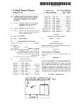
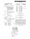
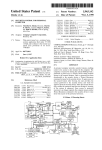
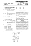
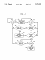
lllllllllllllllllllllllllllllllllllllllllllllllllllllllllllllllIIIIIIIHIII
USOO5359648A
United States Patent [191
[11]
Patent Number:
5,359,648
Dunn et al.
[45]
Date of Patent:
Oct. 25, 1994
[54] ESCAPE SEQUENCE USING MONITORING
OF CONTROL SIGNAL STATES
FOREIGN PATENT DOCUMENTS
0457704 11/1991
[75] Inventors: Tave P. Dunn; Elie A. Jreij, both of
Austin, Tex.; Richard M. Ludwin,
OTHER PUBLICATIONS
ROLMphone User’s Manual; pp. 114 to 11-10.
Poughkeepsie, NY; William ELevene, Austin, Tex.
[73] Assignee:
European Pat. Off. .............. .. 375/8
_
_
.
Primary
Exammer—Curt1s
Kuntz
Assistant Examiner—lason Chan
Rolm Company, Santa Clara, Calif.
[21] Appl. No.: 997,995
[57]
[22] Filed:
A method and apparatus for escaping from transparent
mode in which the Data Communication Equipment
Dec. 28, 1992
5
[51]
[52]
ABSTRACT
will escape from transparent mode (into command
Int. Cl. ..................... .. H04M 11/00; H04L 5/16
US. Cl. ...................................... .. 379/93; 379/94;
mode) if a user programmed escape character string is
received in coincidence with the toggling of a control
_
375/8
[58] Field of Search ..................... .. 379/93, 94, 96, 99,
379/98; 375/84 9’ 121’ 104’ 114
[56]
R f re
Cit d
signal such as Request To Send (RTS). Advanta
geously’ this escape method can be used in conjunction
with time/data escape methods that are based soley on
activity on the received data line. When the two meth
e e nces
e
ods are used together, a supervisor program or control
U.S. PATENT DOCUMENTS
4,549,302 10/1985 Heatherington ...................... .. 375/8
4,926,448
5/ 1990 Kraul et a1. ................... .. 375/121
4,928,305
5/ 1990 Yui ........................................ .. 375/8
device can force an escape notwithstanding the user
Programmed time constraint Parameters in the DCC
17 Claims, 4 Drawing Sheets
102
109
f
105
0
1038
PROCESSOR g
-4
v
T
PROGRAM
5 cm
6 1301
1
M
R
R
S
APPLICATION
K FDATA
1
1
0
I132
E50. SEO.
PROGRAM
107
f T114 1;
120
DATA TRANSFER
WORKING AREA
C
DATA BUFFEHS
1
f
104
,124
125
comm) PROC.
108
\
X
PROCESSOR H
T
122
s
H
‘S
P
a
112
T
2
116
305
/304
ABC OEFG HIJ KLMN
131/
PROGRAM
DATA com. /
Z TELEPHONY /
CONTROL PROC.
’ no
f TELEPHONY /
AU
105
,_ SUPERVISOR
PRUCESSUR
l
r305
XXX
A12 A101 5551212
KEYBUAHD
134
US. Patent
Oct. 25, 1994
Sheet 2 of 4
FIG. 2
TURN OFF
RERUEST TU_ SEND (RTS) /
l
THANSMIT ESCAPE
SEQUENCE DATA /
202
204
L
206
TURN 0N
/
REUUEST TU SEND
FIG. 3
306
/3o4
ABC DEFG HIJ KLMN
l
/308
‘ xxx‘
ATZ ATUT 5551212
:302
FI G. 6
305
/304
ABC DEFG HLJ KLMN
_ l
xxx
fsoa
ATZ ATDT 5551212
602
5,359,648
US. Patent
Oct. 25, 1994
Sheet 3 of 4
FIG. 4
RESET ESCAPE
CHARACTER
COUNTER
ESCAPE CODE
CHARACTER?
INCREMENT
ESCAPE CHARACTER
COUNTER
418
ESCAPE FROM
TRANSPARENT
MODE
5,359,648
1
5,359,648
2
to cause an escape) the characters in the escape se
ESCAPE SEQUENCE USING MONITORING OF
CONTROL SIGNAL STATES
BACKGROUND OF THE INVENTION
quence must arrive separated from one another in time
by less than a predetermined time.
5
A. Field of the Invention
This invention relates to data communication equip
an embodiment of the present invention the Data Com
ment.
munication equipment (DCE) will escape from trans
parent mode if the escape character sequence (the es
cape code) is received in coincidence with the toggling
of a control signal such as Request To Send (RTS).
Advantageously, this escape method can be used in
B. Related Art
Apparatus which perform data communication oper
ations over telephony lines are well known in the art.
For example, it is known to provide a digital telephone
with a data communication controller (DCC) which '
enables an attached computer to communicate with the
conjunction with purely data based escape methods,
digital telephone itself, or with another device (e. g.
another computer) by way of a digital telephony line.
such that a supervisor program or control device can
force an escape notwithstanding user programmed time
Where data communication over an analog telephony
line is desired, a modulator-demodulator (more com
monly known as a “modem”) is used to convert the
constraint parameters in the DCE.
BRIEF DESCRIPTION OF THE DRAWINGS
digital computer generated signals into modulated ana
log signals for transmission over the analog telephony
FIG. 1 is a functional block diagram of a data com
munication device according to an embodiment of the
lines. A modem at a receiving station demodulates the
present invention;
analog signals and converts them back into digital form
for use by a digital device at the receiving end of the
telephony line.
DCCs and modems typically have two modes of
operation: a “transparent mode” in which digital data
from the sending device is passed through to the tele
phony lines (in analog form in the case of a modem), and
a “command mode” in which the DCC or modern will
accept commands from the sending device. For exam
ple, while in command mode the sending device may
have the DCC dial a number or select an incoming or
outgoing line on the digital telephone.
The prior art includes a number of ways of switching
between transparent mode and command mode. For
example, it is known in the art to have a modem switch
from transparent mode to command mode upon recog
nition of a prede?ned escape sequence. The escape
SUMMARY OF THE INVENTION
The present invention comprises a method and appa
ratus for escaping from transparent mode. According to
25
FIG. 2 is a flow chart of the operation of Data Termi
nal Equipment according to an embodiment of the pres
ent invention;
FIG. 3 is a timing diagram of the operation of the data
communication device of FIG. 1;
FIG. 4 is a ?ow chart of the operation of Data Com
munication Equipment of FIG. 1; and
FIG. 5 is a logic diagram of an alternative embodi
ment of the present invention;
FIG. 6 is a timing diagram of an alternative escape
sequence to that of FIG. 3.
Like reference numerals appearing in more that one
?gure depict like elements.
DETAIL DESCRIPTION OF THE PREFERRED
EMBODIMENTS
sequence may take a number of forms. For example, the 40 Turning ?rst to FIG. 1, a DCC of a type suitable for
escape sequence may take the form a non-printable
use with a digital telephone is illustrated. A suitable
character, such as “Ctrl-X” (the “X” key depressed
along with the “Ctrl” key).
One problem with such escape sequences is that,
digital telephone is described, for example, in copend
ing application Ser. No. 07/936,963; ?led Aug. 28, 1992,
which is incorporated by reference herein. The DCC
while in transparent mode, if a sequence of characters 45 includes two microprocessors 102, 104, each of which
matching the escape sequence happens to appear in the
includes an internal Universal Asynchronous Recei
transmitted character stream, the DCC or modem may
ver/Transmitter (UART). The primary microprocessor
undesirably or unexpectedly change from the transpar
ent mode to the command mode. Thus, in DCCs or
modems where it is desired to transmit the escape se
quence characters across the link while in transparent
mode, special provision is made to distinguish a recep
tion (from the computer) of the escape character se
quence which is intended to be retransmitted as data,
from reception of the same escape character sequence
which is intended as a signal for the DCC or modem to
switch from transparent mode to command mode.
The prior art includes a number of mechanisms for
delimiting the “true” escape sequence from a sequence
of characters to be retransmitted. For example, in syn
102 (eg a Motorola 68302) is connected to the internal
data bus 103 of a conventional digital telephone (not
shown), the secondary microprocessor 104, a set of
RS-232 transceivers 106, a random access memory
(RAM) 108 and a read only memory (ROM) 110.
The secondary microprocessor 104 (e.g. a Motorola
6805) is connected to the primary microprocessor 102,
the control bus 105 of the conventional digital tele
phone and a second set of transceivers 112. The trans
ceivers 106, 112 are, in turn, respectively connected to
a ?rst RS-232 port (PORTI) 114 and a second RS-232
port (PORT2) 116. The secondary microprocessor 104
chronous protocols it is known to precede the escape
sequence by prede?ned delimiter characters. For asyn
chronous transmissions, it is known in the art to provide
serves as a conduit between the primary microprocessor
a modem with a mechanism that escapes from transpar
nal code to pass ISDN call status events (received from
102, and the control bus 105 and second RS-232 port
116. The secondary microprocessor 104 includes inter
ent mode, if and only if the escape sequence is preceded 65 the network via the control bus 105) to the primary
microprocessor 102 and to pass commands and re
and/or followed by a predetermined time period during
which no characters are transmitted. Some escape
sponses between the second RS-232 port 116 and the
mechanisms add the additional constraint that (in order
primary microprocessor 102.
3
5,359,648
4
microprocessor and includes a data buffer area for the
RS-232 ports. The ROM 110 includes a number of pro
includes data lines 107 (which carry transmitted and
received data) and control lines 109 (which carry the
RS-232 control signals, such as Data Terminal Ready,
grams (subroutines or processes) which are executed by
Data Set Ready, Clear To Send, and Request To Send).
the primary microprocessor 102. These processes in
The escape sequence of the present invention can be
implemented in a number of different ways. According
The RAM 108 provides workspace for the primary
clude a data transfer processor 120, a telephony control
processor 121, a telephony command processor 122 and
a data communication command processor 124.
The data transfer processor 120 is a timer driven
to a ?rst embodiment, as illustrated in FIG. 2, when the
data terminal equipment (DTE) wants to cause the Data
Communication Equipment to escape from transparent
mode, it ?rst switches the RTS signal from ON to OFF
interrupt routine. The timer (which can be externally
generated or internal to the primary microprocessor)
(Step 202). Next, while maintaining the RTS signal in
the OFF state, the DTE sends a predetermined se
quence of characters (the escape code) over the trans
runs at a suf?cient rate to handle the necessary data
transfer speeds on the RS-232 ports and the telephony
mit signal line (Step 204). Finally, after the last charac
link. The data communication command processor 124
and the telephony control processor 121 run in a main 15 ter in the escape sequence has been transmitted and
before any additional characters are transmitted, the
control loop 125, each processing one piece of informa
DTE switches the RTS signal from OFF to ON (Step
tion if any is present and then passing control to the next
206). Of course the above description implies that the
process. The data communication command processor
RTS signal must be 0N before and after transmission of
124 calls the telephony command processor 122 when
the escape sequence.
ever a user enters a telephony command set (described
A timing diagram of the above-described escape se
in more detail later).
quence showing the toggling of the RTS signal 302 is
The data transfer processor 120 handles normal data
illustrated in FIG. 3. Characters on the DTE’s transmit
transfers between the data bus 103 and the RS-232 com
ted data line (TxD) are indicated by reference numerals
munication ports 114, 116. The data transfer processor
120 also includes code for processing the escape se 25 304, 306 and 308. Before the RTS signal 302 drops to
the OFF (low) state, data 304 is sent on the TxD line
quence which enables a user or applications program,
and the Data Communication Equipment (DCE) is in
connected via an RS-232 port, to change the DCC from
transparent mode. After RTS is turned OFF, the DTE
sends the escape code 306 (“XXX” in the present exam
ple) on the TxD line. Next, following the transmission
of the escape code, and before any additional characters
are sent (by the DTE), the DTE switches the RTS
signal 302 to the ON (high) state. In response, the DCE
switches from transparent mode to command mode and
transparent mode (controlled by the data transfer pro
cessor) to command mode (controlled by either the
telephony command processor or the data communica
tion command processor).
The data communication command processor 124
handles data communication commands of the type well
known in the art. The commands are sent by a con
nected apparatus (e. g. a workstation) via an RS-232 35 the DTE can begin to send a command sequence 308 on
the TxD line.
port. On power up, the DCC defaults to command
FIG. 6 is a timing diagram of an alternative escape
mode and the data communication command processor
sequence to that of FIG. 3. In the escape sequence of
124. The data communication command processor con
FIG. 6, the RTS waveform is toggled during the course
trols the DCC in response to commands in accordance
with the conventional “AT” command set, with exten 40 of transmission of the escape code 306. As a further
sions for activating the telephony command proces
alternative embodiment, a plurality of control signals
sor(s).
(such as RTS and DTR) can be monitored for one or
The telephony control processor 121 handles the
telephony protocol that is received from the telephony
network link. It interprets and responds to telephony
more state changes in conjunction with reception of the
escape code in order to effectuate an escape.
In order to maintain compliance with the RTS speci
?cation in the EIA-232-D standard, it is preferable that
the RTS signal be maintained in the ON state whenever
call status events. In addition, the telephony control
characters (other than the escape sequence) are being
processor 121 sends information from the telephone to
transmitted. It should be understood, however, that in
the link, such as information resulting from key depres
50 systems which do not strictly follow the EIA-232-D
510118.
standard, the RTS signal can generally be OFF and
The telephony command processor 122 handles tele
then turned ON a short time before transmitting the
phony commands. Like the data communication com
escape sequence. In any event, the RTS signal must be
mands, the telephony commands are sent by a con
turned ON for a long enough period of time, before the
nected apparatus via an RS-232 port. Once in command
escape sequence is transmitted, to be detected by the
mode, a user can activate the telephony command pro
escape mechanism.
cessor set by keying the proper AT command sequence
The operation of the Data Communication Equip
(e.g. AT%U). The telephony command processor can
ment (the DCC in the presently described embodiment)
include more than one telephony command set, each of
is illustrated in FIG. 4 From the perspective of the Data
which can be entered by way of a distinct AT com
Communication Equipment, the RTS signal is perpetu
mand.
ally monitored during character transmissions. RTS
A computer workstation 126 can be coupled to either
must ?rst be ON before any escape can be detected.
of the DCC’s communication ports 114, 116 by way of
When RTS is detected to be ON (step 402), the escape
its own RS-232 data communication port 128. An appli
detection mechanism is armed and an escape character
cation program 130, executing on the workstation 126,
can send commands and data to the DCC via the work 65 counter is reset (step 404). While monitoring the RTS
signal (step 406) the escape detection mechanism moni
station’s RS-232 port 128. In accordance with the RS
tors the transmitted data line (TxD) for incoming char
232 standard, the connection between the workstation
acters from the DTE (step 408). If a character is re
communication port and the DCC communication port
commands such as LED cadence commands and ISDN
45
5
5,359,648
ceived it is compared to the speci?ed escape code (step
6
code detector resets and turns itself OFF if the escape
sequence is not received as the ?rst set of characters
410). If the character matches an escape code character,
then the escape character counter is incremented (step
411). If the complete escape code has not been received
subsequent to its being turned ON.
The second timer 514 stops counting and resets when
(step 412) the detection mechanism resumes monitoring
of RTS and TxD (steps 406 and 408). If the character
checked in step 410 is not part of the escape code, then
the escape fails, the DCE remains in transparent mode
sures the time between reception of the escape data
and the detection mechanism returns to step 402 to wait
sequence and the reception of a subsequent character)
for RTS to be ON again.
Once the escape code is determined to be complete
with a second user programmed time value which is
a character is received on the RxD line (as detected by
the character detector 502). A second comparator 516
compares the output of the second timer (which mea
stored within a third register 518. The comparator pro
duces a signal which indicates when the time between
reception of the escape code and the reception of a
subsequent character equals or exceeds the second user
(step 412), the detection mechanism waits for RTS to be
ON (step 414). If any character is received before RTS
is ON (step 416), then the escape fails, the DCE remains
programmed time value. It will be appreciated here that
the ?rst (predecessor) time value need not equal the
second (successor) time value. It will also be appreci
in transparent mode and the detection mechanism re
turns to step 402 to wait for RTS to be ON again. If (in
step 414) it is determined that RTS has been turned on
before any further characters have been received on the
TxD line, the escape is considered to be complete and
ated that in embodiments where one always wants the
predecessor and successor time values to be equal, a
single register can be used. This signal is provided as
one input of a two input OR gate 520.
An Escape Sequence Detector 522 monitors for. re
ception of the escape code in coincidence with toggling
of a control signal (such as RTS) as described with
escape characters are received in proper sequence. If an 25 respect to FIGS. 2-4. A control MUX 524 is pro
grammed by a user (via a register 526) to select any one
escape character is received out of sequence, the detec
of the RS-232 control signals available on the RS-232
tion mechanism will return to step 402.
communication lines connecting the DTE and the
The present escape sequence can be generated in a
DCE. Thus, advantageously, a user can select a signal
number of different ways. In one embodiment, a call
able program (“the escape program”) 132 is provided in 30 other than RTS to monitor for the escape. The output
of the escape sequence detector 522 is connected to the
the workstation 126 to toggle RTS and send the escape
second input of the OR gate 520. Thus, when either
sequence in the appropriate timing. The escape program
escape sequence is detected (the toggling of a control
can then be called by an application program or the
the DCE switches to command mode (step 418).
20
It should be understood that the escape code need not
be a repetition of the same character. In embodiments
where a nonrepetitive escape code (such as “ABC”) can
be chosen, step 410 will also check to ensure that the
operating system (supervisor program 131) whenever
signal in conjunction with reception of the escape data
an escape from transparent mode needs to be accom 35 OR the escape data immediately preceded and suc
plished. Further, the operating system 131 or applica
ceeded by a predetermined period of time during which
tion program 130 can be set up to call the escape pro
gram in response to user depression of a predetermined
key or keys on a keyboard 134. As an alternative em
no characters are received) the DCE will escape from
transparent mode and enter command mode. As a fur
ther modi?cation to the embodiment of FIG. 5, two
bodiment, the appropriate communication port control
40 separate escape sequence character registers can be
instructions can be embedded directly into the supervi
provided such that the two escape sequences can use
sor or user program.
different escape character strings.
Advantageously, the above-described escape se
quence can be used as an alternate escape sequence in
It should be understood that the logic of FIG. 5 can
be embodied in the programming code of the primary
conjunction with a time/data based escape sequence. 45 microprocessor 102 of FIG. 1. Further the mechanism
of FIG. 5 can include the additional constraint that (in
For example, the DCE can be programmed to escape
order to cause an escape) the characters in the escape
when the escape code is preceded and/or followed by a
sequence must arrive separated from one another in
predetermined (user programmed) time period of no
time by less than a predetermined period of time.
characters 0R when RTS is toggled in coincidence with
The advantage of the embodiment of FIG. 5 (or its
reception of the escape code as described above. A
programmed equivalent) is that a supervisor program or
functional block diagram for such an embodiment is
control hardware can force an escape when needed
illustrated in FIG. 5.
without regard to and without disturbing the user pro
A character detector 502 produces a pulse each time
grammed time periods.
a character has been received on the DCE’s RxD line.
Now that the preferred embodiments have been de
The pulse from the character detector 502 resets and 55
starts a timer 504 which is, in turn, connected to a com
scribed, various modi?cations and improvements that
parator 506. The comparator 506 compares the time
do not depart from the scope or spirit of the invention
between character transmissions with a ?rst user pro
will occur to those of skill in the art. Thus, it should be
grammed time value which is stored within a ?rst regis
understood that the preferred embodiments have been
described by way of example and not by way of limita
tion. The scope of the present invention is de?ned by
ter 508. When the time between characters equals or
exceeds the ?rst user programmed time value, it pro
duces a signal which enables (turns on) an escape code
detector 510. The escape code detector monitors the
RxD line and produces a pulse when a string of re
the appended claims.
-
We claim:
1. In a data communication device including an input
ceived characters matches a user programmed escape 65 port for connecting the data communication device to a
utilization device and a telephone port for connecting
character sequence which is stored in a second register
the data communication device to a telephone line; the
512. The pulse from the escape code detector resets and
data communication device having two distinct modes
starts a second timer 514. It is noted here that the escape
7
5,359,648
8
transparent mode, for causing the DCE to switch
of operation: a transparent mode in which the data
communication device provides data received at the
input port to the telephone port, and a command mode
in which the data communication device responds to
the data received at the input port as instructions to the
data communication device; the data communication
device‘ including means for de?ning a predetermined
data; or,
b) the predetermined sequence of data signals occurs
sequence of data as an escape code; the improvement
contiguous in time with at least one occurrence of
to the command mode when:
a) the predetermined sequence of state changes of the
at least one control signal occur in coincidence
with reception of the predetermined sequence of
comprising:
the passage of the predetermined period of time
reception means for receiving at least one control
during which none of the data signals are provided
to the input port;
signal from the utilization device;
coincidence detection means for detecting when a
and, in an absence of both of conditions a and b,
predetermined sequence of state changes of the at
causing the DCE to remain in the transparent
mode.
8. The apparatus of claim 7 wherein the reception
least one control signal occur in coincidence with
reception of the predetermined sequence of data;
15
escape control means, responsive to the means for
means comprises a user programmable multiplexer con
detecting and operative when the data communica
tion device is in the transparent mode, for causing
utilization device; the multiplexor being operative to
the data communication device to switch to the
output a user selected one of the control signals to the
nected to receive a plurality of control signals from the
command mode when the predetermined sequence 20 coincidence detection means.
of state changes of the at least one control signal
occur in coincidence with reception of the prede
termined sequence of data.
2. The apparatus of claim 1 wherein the reception
9. The apparatus of claim 7 wherein the at least one
control signal is Request-To-Send.
10. The apparatus of claim 7 wherein the coincidence
detection means comprises means for detecting a
means comprises a user programmable multiplexor con 25 change of state of the at least one control signal, both
nected to receive a plurality of control signals from the
preceding and succeeding reception of the escape code
utilization device; the multiplexer being operative to
and without reception of any intervening characters.
output a user selected one of the control signals to the
coincidence detection means.
3. The apparatus of claim 1 wherein the at least one
11. The apparatus of claim 10 wherein the coinci
dence detection means further detects a change of state
of the at least one control signal during reception of the
control signal is Request To Send.
escape code.
12. The apparatus of claim 10 wherein the at least one
4. The apparatus of claim 1 wherein the coincidence
detection means comprises means for detecting a
control signal is Request To Send.
change of state of the at least one control signal, both
preceding and succeeding reception of the escape code
and without reception of any intervening characters.
35
5. The apparatus of claim 4 wherein the coincidence
detection means further detects a change of state of the
at least one control signal during reception of the escape
sequence.
6. The apparatus of claim 5 wherein the at least one
control signal is Request To Send.
7. In a data communication device (DCE) including
an input port for connecting the data communication
device to a utilization device and a telephone port for 45
connecting the DCE to a telephone line; the DCE hav
ing two distinct modes of operation: a transparent mode
in which the DCE provides to the telephone port, data
characters de?ned by data signals received at the input
port; and, a command mode in which the DCE re 50
13. A Data Terminal Equipment (DTE) apparatus for
use in conjunction with Data Communication Equip
ment (DCE) having an input port and an output port
and two distinct modes of operation; a transparent
mode in which the DCE provides to the output port,
data characters de?ned by data signals received at the
input port; and, a command mode in which the DCE
responds to the data signals received at the input port as
instructions to the DCE; the DTE comprising:
a communication port comprising a control line and
at least one data line;
data transmission means for sending data characters
on the at least one data line; and,
escape sequence transmission means for toggling a
control signal transmitted on the control line in
coincidence with transmission of an escape code on
the data line such that the DCE will switch from
the transparent mode to the command mode in
response thereto.
14.
The apparatus of claim 13 wherein the DTE in
data signals as an escape code;
means for detecting each occurrence of a passage of a 55 cludes key means for activating the escape sequence
sponds to the data signals received at the input port as
instructions to the DCE; the DCE including:
means for de?ning a predetermined sequence of the
predetermined period of time after provision of one
of the data signals to the input port;
the improvement comprising:
reception means for receiving at least one control
signal from the utilization device;
coincidence detection means for detecting when a
predetermined sequence of state changes of the at
transmission means in response to one or more key
strokes entered by a user.
15. The apparatus of claim 13 wherein the control
signal is Request To Send.
16. The apparatus of claim 13 wherein the escape
sequence transmission means changes the control state
signal during transmission of the escape code.
17. The apparatus of claim 16 wherein the DTE is a
computer workstation and the DCE is an integral part
escape control means, responsive to the means for 65 of a digital telephone.
*
*
*
*
*
detecting and operative when the DCE is in the
least one control signal occur in coincidence with
reception of the predetermined sequence of data;


![mm [mm [1 um um [11115151116 |])|]1]](http://vs1.manualzilla.com/store/data/005839409_1-1dd2adaaab9a040f039445848c9c3135-150x150.png)