1
Chapter 3. Models 40, 50, and 70 Hardware
This chapter provides information about the Models 40, 50, and 70 hardware. The Model 40 is a
nonredundant, single-node system; the Model 50 is a redundant, single-node system; the Model 70 is a
redundant, multinode system.
3.1 Models 40, 50, and 70 Hardware Map Configuration
3.1.1 Model 70 Hardware Map Configuration . . . . .
3.1.2 Model 40 Districts . . . . . . . . . . . . . . . . . .
3.1.3 Model 50 Districts . . . . . . . . . . . . . . . . . .
3.1.4 Model 40 and Model 50 Districts . . . . . . . . .
3.1.5 Model 70 Districts . . . . . . . . . . . . . . . . . .
3.2 MAP for Model 40, 50, and 70 Systems . . . . . . . .
. . . . . . . . . . . . . . . . . . .
3.2.1 Command Line
. . . . . . . . . . . . . . . . . . . . .
3.2.2 MAP Screen
3.2.2.1 MAP Screen Field Descriptions . . . . . . .
3.3 POWER . . . . . . . . . . . . . . . . . . . . . . . . . . .
. . . . . . . . . . . . . . . . . . .
3.3.1 Command Line
. . . . . . . . . . . . . . . . . . .
3.3.2 POWER Screen
3.3.2.1 Interpreting the POWER Screen . . . . . . .
3.4 POWER_SUPPLY . . . . . . . . . . . . . . . . . . . . .
. . . . . . . . . . . . . . . . . . .
3.4.1 Command Line
3.4.2 POWER_SUPPLY Screen . . . . . . . . . . . . . .
3.4.2.1 POWER_SUPPLY Screen Field Descriptions
. . . . . . . . . . . . . . . . . . . . . . . . .
3-3
3-5
3-6
3-6
3-7
3-7
3-8
3-8
3-8
3-8
3-9
3-9
3-9
3-9
3-10
3-10
3-10
3-11
Chapter 3. Models 40, 50, and 70 Hardware
3-1
. . . . . . . . . . . . . . . . . . . . . . . . . .
. . . . . . . . . . . . . . . . . . . . . . . . . .
. . . . . . . . . . . . . . . . . . . . . . . . . .
. . . . . . . . . . . . . . . . . . . . . . . . . .
. . . . . . . . . . . . . . . . . . . . . . . . . .
. . . . . . . . . . . . . . . . . . . . . . . . . .
. . . . . . . . . . . . . . . . . . . . . . . . . .
. . . . . . . . . . . . . . . . . . . . . . . . . .
. . . . . . . . . . . . . . . . . . . . . . . . . .
. . . . . . . . . . . . . . . . . . . . . . . . . .
. . . . . . . . . . . . . . . . . . . . . . . . . .
. . . . . . . . . . . . . . . . . . . . . . . . . .
. . . . . . . . . . . . . . . . . . . . . . . . . .
. . . . . . . . . . . . . . . . . . . . . . . . . .
. . . . . . . . . . . . . . . . . . . . . . . . .
. . . . . . . . . . . . . . . . . . . . . . . . .
. . . . . . . . . . . . . . . . . . . . . . . . .
3-2
Configuration Manual, Release 9005/9006m
3.1 Models 40, 50, and 70 Hardware Map Configuration
The Model 40, 50, and 70 systems have the following types of hardware shelves:
•
Central processing unit (CPU) (processor-related hardware)
•
Time-division multiplexing (TDM)
•
−
CNFG
−
UNIV 18 filter panel (for upgrade systems)
−
UNIV1 23 filter panel
Internode link (INL) (Model 70 only)
Shelf 2 is the CPU shelf. The remaining shelves can be configured as either CNFG or UNIV1. A CNFG
shelf is a TDM shelf with configurable motherboards. A UNIV1 shelf is a TDM shelf with the universal
motherboard. It is not possible to configure cards in slot 5 on any shelf.
Table 3-1 lists the hardware that you can use with Model 40, 50, and 70 systems, shelf allocations, and
district types. This table will assist you in configuring the MAP screen (shown in Figure 3-1 on
page 3-8).
Table
3-1 (Page 1 of 2). Models 40, 50, and 70 Hardware, Shelf Allocations, and District Types
Hardware
Shelf
District Type
Card
Mnemonic
Advanced diagnostics card
CNFG, UNIV, or UNIV1
ADC, CRELEC, MUNI, or UNI
ADC
Analog telephone interface
(8-channel)
CNFG, UNIV, or UNIV1
ATI, MUNI, or UNI
ATI
Attendant console controller
(1-channel)
CNFG, UNIV, or UNIV1
MUNI or UNI
ACC
Central office trunk (8-channel)
CNFG or UNIV1
MUNI or UNI
COT
CODEC card
CNFG
DIR, KTI, OPS, or 8CHMW
CODEC
Conference bridge
CNFG, UNIV, or UNIV1
CONF, CRELEC, MUNI, or UNI
CONF
Control packet network interface
CPU
CPNI
CPNI
Control packet network junction
CNFG
CPNJ
CPNJ
Data frontend II
CNFG, UNIV, or UNIV1
CRELEC, DFEII, MUNI, or UNI
DFEII
Direct inward dial trunk (8-channel)
(with CODEC)
CNFG
UTC
DID
Direct inward dial trunk (8-channel)
CNFG or UNIV1
MUNI or UNI
DID8
Direct trunk
CNFG
DIR
DIR
Diskette assembly
CPU
FDISK
FDISK
Dual-tone receiver
CNFG, UNIV, or UNIV1
CRELEC, DIGTRK, DTR, MUNI, or
UNI
DTR
Expander III
CNFG, UNIV, or UNIV1
EXP
EXP
Expander IIIE
CNFG, UNIV, or UNIV1
EXP
EXP
Hard disk assembly
CPU
HDISK
HDISK
ISDN primary digital network (IPDN)
CNFG, UNIV, or
UNIV1 2
CRELEC, DIGTRK, MUNI, PRI, or UNI
IPDN
Local shelf monitor
CNFG, UNIV, or UNIV1
LS M
LSM
Master clock synchronization
module
CNFG, UNIV, or UNIV1
MCSM
MCSM
Message waiting (8-channel) (with
CODEC)
CNFG
8CHMW
MW
Chapter 3. Models 40, 50, and 70 Hardware
3-3
Table
3-1 (Page 2 of 2). Models 40, 50, and 70 Hardware, Shelf Allocations, and District Types
Hardware
Shelf
District Type
Card
Mnemonic
Message waiting (8-channel)
CNFG or UNIV1
MUNI or UNI
MW8
Off-premises station (8-channel)
(with CODEC)
CNFG
OPS or 8CHMW
OPS
Off-premises station (8-channel)
CNFG or UNIV1
MUNI or UNI
OPS8
Outbound dialer interface 3
CNFG, UNIV, or UNIV1
MUNI or UNI
ACC
Peripheral device controller
CPU
PDC
PDC
ROLM private digital network
(RPDN)
CNFG
RPDN
RPDN
ROLMbridge 5250
CNFG
RB5250
RB5250
ROLMlink interface (16-channel)
CNFG or UNIV1
MUNI, RLI, or UNI
RLI
Rotary register
CNFG, UNIV, or UNIV1
CRELEC, MUNI, ROTR, or UNI
ROTR
Rotary sender
CNFG, UNIV, or UNIV1
CRELEC, MUNI, ROTS, or UNI
ROTS
Slave clock synchronization module
CNFG or UNIV1
SLCSM
SLCSM
System monitor I/O card
CPU
SMIOC
SMIOC
T1 digital network (T1DN) card
(24-channel)
CNFG or UNIV1
DIGTRK, MUNI, or UNI
T1
TDM controller card
CPU
TC
TC
TDM controller and turnaround
stand-alone card
CPU
TCTASA
TCTASA
Tie trunk (8-channel)
CNFG
UTC
TIE
Tone sender
CNFG, UNIV, or UNIV1
CRELEC, DIGTRK, MUNI, TONE, UNI
TONE
Turnaround stand-alone
CPU
TASA
TASA
Universal trunk controller (4-wire)
(8-channel)
CNFG
UTC
UTC
4-wire tie trunk interface (4-channel)
CNFG or UNIV1
MUNI, TTI, or UNI
TTI
9030 central processing unit
CPU
CPUNR
CPU
CPUR 1
9030A CPU card
CPU
CPUNR or
9030A I/O bus switch
CPU
CPUNR or CPUR 1
CPU
IOBUS
9030 m e m o r y
CPU
CPUNR
12MEG
9030A memory expansion
CPU
CPUNR or CPUR 1
MEM
9030 memory controller
CPU
CPUNR
MEMCON
Note: Two mnemonics that were not shown in Table 3-1 on page 3-3 are EMPTY and VAC. An EMPTY
slot cannot be filled with a card. (The EMPTY mnemonic is not displayed on the screen.) A VAC
(vacant) slot can be filled with a card but happens to be unoccupied.
1
CPUR applies only to Model 50 and Model 70 systems.
2
The IPDN card must reside on the same shelf as its corresponding T1DN card.
3
Refer to the CallBridge System Service and Configuration Guide for the CSTA and IBM SwitchServer/2 Options, Release 1.0 ,
for configuration information.
3-4
Configuration Manual, Release 9005/9006m
3.1.1 Model 70 Hardware Map Configuration
In addition to the hardware listed in Table 3-1 on page 3-3, Table 3-2 lists the hardware needed in
Model 70 systems.
Table
3-2. Model 70 Hardware, Shelf Allocations, and District Types
Hardware
Shelf
District Type
Card Mnemonic
Control packet network port
INL
XR
CPNP
Control packet network remote interface
CNFG
CPN or XDI
CPNRI
Extended digital intertie
CNFG
XDI
XDI
Fiber-optic interface
CNFG or INL
FIBER or FBR3
FOX
Software Release
9005.1.70 and
Above: FIBER
INL transmit and receive
INL
XR
XR
Turnaround multinode A and B (cards 1
and 2 for both)
INL
TA
TAMA1, TAMA2,
TAMB1, and
TAMB2
Chapter 3. Models 40, 50, and 70 Hardware
3-5
3.1.2 Model 40 Districts
The following are the district types that reside on the CPU and UNIV1 shelves in a Model 40 system.
CPU Shelf when Model 40 has the 9030 CPU Card: The following are district types that reside on the
CPU shelf when the Model 40 has the 9030 CPU card:
•
TASA
•
TC
•
CPUNR
•
SMIOC
•
PDC
•
FDISK
•
HDISK
CPU Shelf when the Model 40 has the 9030A CPU Card: The following are district types that reside on
the CPU shelf when the system has the 9030A CPU card:
•
TASA
•
TC
•
TCTASA
•
CPUNR
•
IOBUS
•
SMIOC
•
PDC
•
FDISK
•
HDISK
The Model 40 nonredundant 9030A CPU system has two possible configurations:
•
Both a TC and a TASA card
•
A single TCTASA card
UNIV1 Shelf: The following is a district type that resides on the UNIV1 shelf:
•
UNI
3.1.3 Model 50 Districts
The following are district types that reside on the CPU shelf:
•
TCTASA
•
MEM
•
CPUR
•
IOBUS
•
SMIOC
•
PDC
3-6
Configuration Manual, Release 9005/9006m
•
FDISK
•
HDISK
3.1.4 Model 40 and Model 50 Districts
The following are district types that can reside on the CNFG shelves in a Model 40 or 50 system:
•
DIGTRK
•
MCSM
•
MUNI
•
SLCSM
•
RB5250
3.1.5 Model 70 Districts
The following are district types used in Model 70 systems:
•
CPNI
•
CPNJ
•
XR
•
XDI CPN
•
TA
•
XDI
•
XR
•
FIBER or FBR3
Chapter 3. Models 40, 50, and 70 Hardware
3-7
3.2 MAP for Model 40, 50, and 70 Systems
The following sections describe the MAP command, screen, and field descriptions.
3.2.1 Command Line
The following commands function in the MAP screen:
COUNT
CREATE
DELETE
LIST
MODIFY
MAP < p h y s i c a l a d d r e s s o r A L L >
The PAD format is nn/xxyy where:
nn is the node number
xx is the shelf number
yy is the slot number
3.2.2 MAP Screen
Figure 3-1 shows a sample MAP screen in CREATE mode.
COMMAND: CREATE MAP ALL
HWMAP
PAD
------01/0307
Figure
SHELF
TYPE
----UNIV1
DISTRICT
TYPE
SL TYPE SL TYPE SL TYPE SL TYPE SL TYPE
------ -- ----- -- ----- -- ----- -- ----- -- ----UNI
07 OPS8
3-1. Sample MAP Screen in Model 40 and Model 50 Systems
3.2.2.1 MAP Screen Field Descriptions
The descriptions of the fields in the MAP screen are as follows:
HWMAP PAD
This display-only field contains the physical address (PAD) of the first slot in the
group. This field gets its value from the command line.
SHELF TYPE
This field displays the shelf type. Valid values are: CNFG, CPU, UNIV, or UNIV1.
This field can be modified only if the record is deleted and re-created. Shelf 2 is the
dedicated CPU shelf.
DISTRICT TYPE
This field displays the district type. Enter ? in this field to view the possible values.
For more information refer to the following:
•
•
•
•
•
2.1.2,
3.1.4,
3.1.2,
3.1.3,
3.1.5,
“Model
“Model
“Model
“Model
“Model
10
40
40
50
70
District Types” on page 2-5
and Model 50 Districts” on page 3-7
Districts” on page 3-6
Districts” on page 3-6
Districts” on page 3-7.
SL
This display-only field contains the physical slot number.
TYPE
This field shows the card types that make up the district.
3-8
Configuration Manual, Release 9005/9006m
Chapter 8. Station Equipment
This chapter describes the station equipment and configuration. This description explains how the
hardware and software work together.
|
|
|
|
|
|
|
|
. . . . . . . . . . . . . . . .
8-3
8-4
8-4
8-5
8-5
8-9
8-9
8-9
8-9
8-11
8-11
8-12
8-13
8-16
8-16
8-17
8-18
8-19
8-19
8-20
8-21
8-29
8-29
8-30
8-30
8-30
8-31
8-31
8-36
8-36
8-37
8-41
8-42
8-43
8-46
8-47
8-48
8-48
8-48
8-49
8-49
8-50
8-51
8-56
8-56
8-56
8-57
8-60
Chapter 8. Station Equipment
8-1
8.1 MAP for a Single-Line Telephone . . . . . . . . . . . . . . . . . . . .
8.2 SLI . . . . . . . . . . . . . . . . . . . . . . . . . . . . . . . . . . . . . . .
. . . . . . . . . . . . . . . . . . . . . . . . . . . .
8.2.1 Command Line
. . . . . . . . . . . . . . . . . . . . . . . . . . . . . . .
8.2.2 SLI Screen
8.2.2.1 SLI Screen Field Descriptions . . . . . . . . . . . . . . . . .
8.3 VRU_PROTOCOL . . . . . . . . . . . . . . . . . . . . . . . . . . . . . .
8.3.1 Command Line
. . . . . . . . . . . . . . . . . . . . . . . . . . . .
8.3.2 VRU_PROTOCOL Screen . . . . . . . . . . . . . . . . . . . . . . .
8.3.2.1 VRU_PROTOCOL Screen Field Descriptions
. . . . . . . .
. . . . . . . . . . . . . . . . . . .
8.4 EXTEN for Single-Line Telephones
. . . . . . . . . . . . . . . . . . . . . . . . . . . .
8.4.1 Command Line
8.4.2 EXTEN Screen for Single-Line Telephones . . . . . . . . . . . .
8.4.2.1 Configuring the EXTEN Screen for Single-Line Telephones
8.5 AVAIL for Extensions and Data Lines . . . . . . . . . . . . . . . . . .
8.5.1 Command Line
. . . . . . . . . . . . . . . . . . . . . . . . . . . .
8.5.2 AVAIL Screen
. . . . . . . . . . . . . . . . . . . . . . . . . . . . .
8.5.2.1 AVAIL Screen Field Descriptions
. . . . . . . . . . . . . . .
. . . . . . . . . . . . . . . . . . . . . . . . . . . . . . . . . . . . . .
8.6 LEX
. . . . . . . . . . . . . . . . . . . . . . . . . . . .
8.6.1 Command Line
8.6.2 LEX Screen . . . . . . . . . . . . . . . . . . . . . . . . . . . . . . .
8.6.2.1 LEX Screen Field Descriptions . . . . . . . . . . . . . . . . .
8.7 ROLMphone Features . . . . . . . . . . . . . . . . . . . . . . . . . . .
8.7.1 Features Requiring Light-Emitting Diodes . . . . . . . . . . . . .
. . . . . . . .
8.7.2 ROLMphone Features Requiring Index Numbers
8.7.3 Speakerphone . . . . . . . . . . . . . . . . . . . . . . . . . . . . .
. . . . . . . . . . . . . . . . . . . . . . . . . . . . . .
8.7.4 Flash Button
. . . . . . . . . . . . . . . . . . . . . . .
8.7.5 ACD Emergency Button
8.7.6 ROLMphone Feature Descriptions . . . . . . . . . . . . . . . . .
. . . . . . . . . . . . . . . . . . . . . . . . . . . . . . . . . . .
8.8 BUTTON
. . . . . . . . . . . . . . . . . . . . . . . . . . . .
8.8.1 Command Line
8.8.2 BUTTON Screen . . . . . . . . . . . . . . . . . . . . . . . . . . . .
. . . . . . . . . . . . . . .
8.8.2.1 Configuring the BUTTON Screen
8.8.2.2 BUTTON Screen Field Descriptions . . . . . . . . . . . . . .
8.8.2.3 BUTTON Defaults for Software Reduced Feature Mode . .
. . . . . . . . . . . . . . . .
8.8.2.4 Feature Button Validity Checks
. . . . . . . . . . . . . . . . . . .
8.9 MAP for a ROLMphone Telephone
8.10 RPS_ON . . . . . . . . . . . . . . . . . . . . . . . . . . . . . . . . . . .
8.10.1 Command Line . . . . . . . . . . . . . . . . . . . . . . . . . . . .
. . . . . . . . . . . . . . . . . . . . . . . . . . .
8.10.2 RPS_ON Screen
8.11 RP . . . . . . . . . . . . . . . . . . . . . . . . . . . . . . . . . . . . . .
8.11.1 Command Line . . . . . . . . . . . . . . . . . . . . . . . . . . . .
8.11.2 RP Screen . . . . . . . . . . . . . . . . . . . . . . . . . . . . . . .
8.11.2.1 RP Screen Field Descriptions . . . . . . . . . . . . . . . . .
8.12 EXTEN for ROLMphone Telephones . . . . . . . . . . . . . . . . . .
8.12.1 Command Line . . . . . . . . . . . . . . . . . . . . . . . . . . . .
8.12.2 EXTEN Screen for ROLMphone Telephones . . . . . . . . . . .
8.12.2.1 Configuring the EXTEN Screen for ROLMphones . . . . .
. . . . . . . . . . . . . . . . . . . . . . . . . . . . . . . .
8.13 FACEPLATE
. . . . . . . . . . . . . . . . .
. . . . . . . . . . . . . . . . .
. . . . . . . . . . . . . . . . .
. . . . . . . . . . . . . . . . .
. . . . . . . . . . . . . . . . .
. . . . . . . . . . . . . . . . .
. . . . . . . . . . . . . . . . .
. . . . . . . . . . . . . . . . .
. . . . . . . . . . . . . . . . .
. . . . . . . . . . . . . . . .
. . . . . . . . . . . . . . . .
. . . . . . . . . . . . . . . .
. . . . . . . . . . . . . . . .
. . . . . . . . . . . . . . . .
. . . . . . . . . . . . . . . .
. . . . . . . . . . . . . . . .
. . . . . . . . . . . . . . . .
. . . . . . . . . . . . . . . .
. . . . . . . . . . . . . . . .
. . . . . . . . . . . . . . . .
. . . . . . . . . . . . . . . .
. . . . . . . . . . . . . . . .
. . . . . . . . . . . . . . . .
. . . . . . . . . . . . . . . .
. . . . . . . . . . . . . . . .
. . . . . . . . . . . . . . . .
. . . . . . . . . . . . . . . .
. . . . . . . . . . . . . . . .
. . . . . . . . . . . . . . . .
. . . . . . . . . . . . . . . .
. . . . . . . . . . . . . . . .
. . . . . . . . . . . . . . . .
. . . . . . . . . . . . . . . .
. . . . . . . . . . . . . . . .
. . . . . . . . . . . . . . . .
. . . . . . . . . . . . . . . .
. . . . . . . . . . . . . . . .
. . . . . . . . . . . . . . . .
. . . . . . . . . . . . . . . .
. . . . . . . . . . . . . . . .
. . . . . . . . . . . . . . . .
. . . . . . . . . . . . . . . .
. . . . . . . . . . . . . . . .
. . . . . . . . . . . . . . . .
. . . . . . . . . . . . . . . .
. . . . . . . . . . . . . . . .
. . . . . . . . . . . . . . . .
8.13.1 Displaying Faceplates on the Terminal
. . . . . . . . . . . . .
8.13.2 Printing Faceplates Using the Printer Attached to the Terminal
8.13.3 Printing Faceplates Using the RPFP Port Printer . . . . . . . .
8.13.4 Command Line . . . . . . . . . . . . . . . . . . . . . . . . . . . .
8.13.5 FACEPLATE Screen . . . . . . . . . . . . . . . . . . . . . . . . .
8.13.5.1 FACEPLATE Screen Field Descriptions . . . . . . . . . . .
8-2
Configuration Manual, Release 9005/9006m
. . . . . . . . . . . . . . . .
. . . . . . . . . . . . . . .
. . . . . . . . . . . . . . . .
. . . . . . . . . . . . . . . .
. . . . . . . . . . . . . . . .
. . . . . . . . . . . . . . . .
8-60
8-60
8-60
8-62
8-62
8-63
8.1 MAP for a Single-Line Telephone
The MAP command permits you to view the hardware map to get the physical address (PAD) of cards
configured in the 9751 computerized branch exchange (CBX). You need the PAD to use the SLI
command shown in 8.2, “SLI” on page 8-4.
Figure 8-1 is an example of a universal district for standard analog telephones as it appears in the
MAP database of a Model 10.
COMMAND: LIST MAP 0218
HWMAP DISTRICT
PAD TYPE
------- -----DS 01/0218 UNI
DS 01/0219 UNI
DS 01/0220 UNI
Figure
SL TYPE
-- -----18 ATI
19 MW8
20 OPS8
8-1. Sample UNI District in the MAP Database of a Model 10
Refer to 2.2, “MAP for Model 10 Systems” on page 2-8 and 3.2, “MAP for Model 40, 50, and 70
Systems” on page 3-8 for further information on the MAP command.
Chapter 8. Station Equipment
8-3
8.2 SLI
The following sections discuss the SLI screen and how to configure the PAD for a single-line extension.
8.2.1 Command Line
The following commands function in the SLI screen:
COUNT
CREATE
DELETE
LIST
MODIFY
SLI
<physical address or ALL>
In the command line, <physical address> is the PAD of the single-line extension you want to
configure. This address must exist in the MAP database.
The PAD format is nn/xxyyzz, where:
nn is the node number
xx is the shelf number
yy is the slot number
zz is the channel number of the single-line extension
8-4
Configuration Manual, Release 9005/9006m
GN25-2890-00 to G341-1505-05
8.2.2 SLI Screen
Figure 8-2 is an example of the first line on the SLI screen used to create a new single-line extension.
COMMAND: CREATE SLI 01/030603
|
|
|
|
|
|
DF
CR
| Figure
PAD
-------->
01/030603
REF
---0
0
USE
--EXT
MUS
MUSIC
CHNL
-->
2
DIAL
TYPE
D
D
EXTN
--->
*9008
FLASH
TEST PHONE
?
N
N
N
ACD
BSY HR
USAGE%
--?
?
8-2. Sample SLI Screen—Line 1 in a System with Software Release 9005.6.83 and Above
If the PAD entered in the PAD field belongs to an OPS8 or MW8 card, the system automatically
refreshes the first line of the SLI screen, enters N in the TEST field, and then displays a new line of
fields. 1 Figure 8-3 shows the first line on the SLI screen after it has been refreshed.
COMMAND: CREATE SLI 030603
|
|
|
|
|
DF
CR
| Figure
MUSIC
PAD
REF USE CHNL EXTN
--------- ---- --- -------->
0
EXT >
01/030603
DIAL
FLASH
TYPE TEST PHONE
D
?
N
N
8-3. Sample SLI Screen—Line 1 Refreshed in a System with Software Release 9005.6.83 and Above
The new line of fields (shown in Figure 8-4) permits you to enter extra information needed for the OPS8
and MW8 PADs. This line appears only if the PAD entered belongs to an OPS8 or MW8 card.
|
|
|
|
|
DF
CR
| Figure
| Above
BALANCE
NETWORK
2
ON
PREMISE
N
WINK
OFF
N
TERM
ONLY
N
VRU
PROTOCOL
-------NONE
FOO
8-4. Sample SLI Screen—Line 2 (OPS8 and MW8 Only) in a System with Software Release 9005.6.83 and
8.2.2.1 SLI Screen Field Descriptions
Because the SLI screen has so many fields, the field descriptions are listed following the line they
describe.
Configuring the SLI Screen—Line 1: The field descriptions are as follows:
PAD
1
If you entered ALL in the command line, the system enters the next available PAD.
Otherwise, the PAD entered in the command line appears in this field.
When the TEST field is N, the TEST OPS and TEST MW8 CLI commands do not run. The system sets this field to N since the
OPS8 and MW8 cards do not have any tests that need to be disabled.
Chapter 8. Station Equipment
8-5
GN25-2890-00 to G341-1505-05
REF
Reference number. This is an optional field. Enter up to four digits (0 to 9999) as a
comment referring to information sources such as a definition sheet, a cable
number, a floor number, a jack number, or an office number. This stored number
is displayed on the screen but is not used by the 9751 CBX. The default is 0.
USE
Enter one of the following channel names:
CHI
This channel is connected to the night chime source. Only one is permitted
per attendant console group. Universal night answer (UNA) trunks must be
configured for this feature to work.
DIC
This channel is connected to a dictation device.
EXT
This channel is connected to a single-line telephone.
FAX
Software Release 9005.6.80 and Above with CorNet-N: This channel is
connected to a facsimile (FAX) device.
MOD
This channel is connected to a system modem.
MPL
Modem pool extension. Enter this value:
•
For all modems in the system
•
If you want CDR statistics gathered on any of the modems
•
If this extension will be assigned to a data line that will be placed in a
modem pool
This extension number can be dialable.
MUS
This channel is connected to the music on hold source. If music is part of
the 9751 CBX, define one music channel for each node.
REC
This channel is connected to a recorded announcement device. Only one
modem is permitted (required) per node. (This value applies only if there
is no 9751 CBX monitor or 9751 CBX monitor II.)
The default is EXT.
Note: The customer provides the music, chimes, dictation, and recording
equipment.
| MUSIC CHNL
|
This field indicates the music or recorded-source channel assigned to this
single-line extension.
|
|
Software Release 9005.6.82 and Below: The system enters 1 in this field and skips
it.
a
|
Software Release 9005.6.83: Enter the music (or other recorded-source) channel
assigned to this COS. Enter a value from 1 to 3.
|
Enter one of the following:
|
1
Music channel 1.
|
|
2
Music channel 2. This value applies only if the extension has
multiple music on hold associated with its COS.
|
|
3
Music channel 3. This value applies only if the extension has
multiple music on hold associated with its COS.
|
There is no default.
|
|
|
Ensure that the single-line PADs designated for music-on-hold are
configured and connected to a music or recording source. Otherwise,
silence (not music) is heard from the channel.
a
Software Release 9005.6.84: Enter a value from 1 to 64.
8-6
Configuration Manual, Release 9005/9006m
EXTN
Enter the 1- to 7-digit extension number for the channel.
•
If the USE field entry is EXT, DIC, or MOD, the number entered must be a
dialable extension and begin with a valid first digit as configured in the
FIRST_DIGIT table. For further information, refer to Chapter 5, “First-Digit
Assignments.”
•
If the USE field entry is MUS, CHI, or REC, the number entered must be a
nondialable extension number that includes an asterisk ( ) as the first digit.
*
Note: If the USE field is MPL, this extension number can be dialable or
nondialable.
*
and number as a feature
A nondialable extension can begin with the same
access code. Refer to Chapter 9, “Feature Access Codes” for further
must not exceed seven.
information. The total number of digits including the
*
In all cases, the number must be unique, that is, it must not appear anywhere else
in the 9751 CBX. There is no default.
If you enter an extension number that has not yet been configured, the system
automatically provides the EXTEN screen when the SLI is complete. The EXTEN
screen is shown in Figure 8-6 on page 8-12.
DIAL TYPE
Enter the station dial type as follows:
D
Dual-tone multifrequency (DTMF). Enter D if the USE field contains FAX.
R
Rotary
B
Both
The default is D.
TEST
Indicates that the 9751 CBX will test the channel. Enter Y to test this channel; enter
N and this channel is not tested.
The default is N.
FLASHPHONE
Use this field for message waiting telephones. Enter Y if you want a light activated
on a message waiting telephone; enter N if you do not.
If you attempt to configure a Flashphone on an ATI or OPS card, the 9751 CBX
changes your Y entry to N.
The system enters N in this field and skips it if the USE field contains FAX.
The default is N.
Software Release 9005.1.73 and Below: This field does not apply to Model 10
systems because Flashphone telephones are not supported.
ACD BSY HR USAGE%
Software Release 9005.2.77 and Above: This field appears only in systems with
ACD.
This field indicates the busy-hours usage percentage level of the ACD telephones.
Enter one of the following:
25
The ACD telephones have a low busy-hours usage level. This level
corresponds to 6 centum calls per second (CCS).
50
The ACD telephones are moderately active. This level corresponds to 12
CCS.
75
The ACD telephones are highly active. This level corresponds to 18 CCS.
100
The ACD telephones are fully active. This level corresponds to 25 CCS.
Chapter 8. Station Equipment
8-7
The default is 100.
The system skips this field unless the USE field is EXT.
Each station is assigned 7 CCS per busy hour for voice traffic. Each station is able
to handle traffic up to 32 CCS per hour, depending on the system′s configuration.
If the system displays a message that indicates there are problems, refer to the
systems engineer.
Configuring the SLI Screen—Line 2 (OPS8 and MW8 Only): The fields shown in Figure 8-4 on page 8-5
are described in the following.
BALANCE NETWORK
This field determines which balance network will be used to match the impedances of
the OPS8 channel and the OPS facility.
Enter one of the following:
1
600 ohms impedance. Enter this value if the telco terminating equipment is
onsite.
2
Compromise network. This value enables most facility impedances to be
matched.
3
Longloop A. This value indicates a special network for long cable lengths.
4
Longloop B. This value indicates an additional special network for long cable
lengths.
Determine the correct value for OPS trunks as follows:
1. Permit this field to default.
2. Run the verify balance channel test (Test BALANCE).
3. Check the value recommended by the channel test.
4. Modify this field′ s value if the value given is not equal to the default.
The default is 2.
ON PREMISE
Enter Y to indicate that this extension is on the premises; enter N if it is off the
premises. The default is N.
WINK OFF
Enter Y to indicate that this extension should receive a wink-off signal; enter N if it
should not. The default is N.
TERM ONLY
Enter Y to indicate that this extension is a terminating-only device; enter N if it is not.
The default is N.
Software Release 9005.1.75 and Above: If you enter Y in this field, ensure that this
extension has TRM COS.
| VRU PROTOCOL
|
This field determines the outpulse protocol. Enter NONE or an 8-character
|
alphanumeric name.
|
|
Note: This protocol must already be configured in the system through the
VRU_PROTOCOL command before it is entered in this field.
|
Refer to 8.3, “VRU_PROTOCOL” on page 8-9 to configure the T1 OPS VRU protocol.
8-8
Configuration Manual, Release 9005/9006m
|
8.3 VRU_PROTOCOL
| Software Release 9005.6.83 and Above: Use this screen to configure the protocol used to outpulse
| digits. Configure up to 10 protocols in the system.
|
8.3.1 Command Line
| The following commands function in the VRU_PROTOCOL screen:
|
|
|
|
CREATE
DELETE
LIST
MODIFY
VRU_PROTOCOL <name>
| In the command line, <name> is a 1- to 8-character alphanumeric name.
| You cannot delete a VRU_PROTOCOL while it is referenced by an OPS channel.
| Use the XREF_VRU command to list the OPS channels that reference a particular protocol. Refer to
| 12.9, “XREF_VRU” on page 12-88.
|
8.3.2 VRU_PROTOCOL Screen
| Use the VRU_PROTOCOL command (as shown in Figure 8-5) to configure the protocol used to outpulse
| digits.
|
|
|
|
|
|
|
|
|
|
|
COMMAND: CREATE VRU_PROTOCOL FOO
P
A
U
S
NAME
E DELIMITER
-------- - ---------DF>
0
CR> FOO
1 1234567890
| Figure
P
A
U
ANI/
S
ANI/
DNIS DELIMITER E DELIMITER DNIS DELIMITER
---- ---------- - ---------- ---- ---------NONE
0
NONE
DNIS #
1 6789ABCD*# ANI #
8-5. Sample VRU_PROTOCOL Screen
| 8.3.2.1 VRU_PROTOCOL Screen Field Descriptions
| Each of the entries in the protocol table is configurable based on the following protocol format:
|
[<Pause><Delimiter><Digits><Delimiter>] [ <Pause><Delimiter><Digits><Delimiter>]
| The field are described as follows:
| NAME
|
This field′s value comes from the command line. It contains a 1- to 8-character
alphanumeric protocol name.
| PAUSE
|
Enter the length of the delay (in seconds) before the system begins outpulsing
digits. Enter a value from 0 to 9. The default is 0.
| DELIMITER
|
This field indicates the end-of-digit-string to the VRU machine. Enter a delimiter
string of up to 10 digits using numerals 0 to 9, , and #. The default is NONE.
*
Chapter 8. Station Equipment
8-9
| ANI/DNIS
|
This field indicates if an ANI or DNIS digit string is to be outpulsed. Enter one of
the following:
|
ANI
An ANI digit string is outpulsed.
|
DNIS
A DNIS digit string is outpulsed.
|
NONE
No digit string is outpulsed.
|
The default is NONE.
8-10
Configuration Manual, Release 9005/9006m
8.4 EXTEN for Single-Line Telephones
When you create a single-line extension using the CREATE SLI command and the extension has not yet
been defined in the 9751 CBX, the EXTEN screen appears. Use the EXTEN screen to configure
single-line attributes.
8.4.1 Command Line
The following commands function in the EXTEN screen:
COUNT
CREATE
DELETE
LIST
MODIFY
EXTEN
<extension number or ALL>
In the command line, <extension number> is a 1- to 7-digit extension number.
Warning: Use the DELETE EXTEN command carefully. If you delete an extension using this command,
you will remove it from the software and the hardware. If you want to keep the extension in software,
delete the hardware in the SLI database using the DELETE SLI <physical address> command. You
cannot exchange extensions in software. The DELETE EXTEN command does not delete the extension
number from the SYSTEM FORWARDING TARGET fields.
Software Release 9005.6.80 and Above with CorNet-N:
•
You cannot CREATE, MODIFY, or DELETE remote extensions through the EXTEN screen—use
the REXTEN screen.
•
You cannot use the MODIFY EXTEN command to modify an extension to make it a remote
extension. If you attempt to do this, the system displays a message.
Chapter 8. Station Equipment
8-11
8.4.2 EXTEN Screen for Single-Line Telephones
Figure 8-6 shows a sample EXTEN screen that is used to configure unique single-line extensions.
These fields permit you to set extension attributes for an extension number not yet defined in the 9751
CBX.
COMMAND: CREATE EXTEN 4020
FORWARD ON
SYSTEM
FORWARDING
BSY RNA DND
EXTN
TYPE COS TARGET 1 TARGET 2 TARGET 3 TARGET 4 I E I E I E RINGDOWN
------- --- --- -------- -------- -------- -------- - - - - - - -------DF >
>
0
-----CR 4020
ACD NAME
- ---------------DF N
CR
Figure
Above
8-6. Sample EXTEN Screen for Single-Line Attributes in a System with Software Release 9005.1.73 and
Software Release 9005.1.60 and Below: There can be up to two forwarding targets.
Software Release 9005.1.73 and Above: There can be up to four forwarding targets.
8-12
Configuration Manual, Release 9005/9006m
8.4.2.1 Configuring the EXTEN Screen for Single-Line Telephones
Configure the fields as follows:
EXTN
If you entered the EXTEN screen through the SLI screen, the system enters the
value from the EXTN field of the SLI screen (shown in Figure 8-2 on page 8-5) into
this field. Otherwise, this field contains the extension number entered in the
command line.
TYPE
Enter one of the following types of extensions:
|
|
CHI
Night chime extension
DIC
Dictation device
EXT
Single-line or ROLMphone telephone
FAX
Software Release 9005.6.80 and Above with CorNet-N: Facsimile device
MOD
System modem
MPL
Modem pool extension
MUS
Music-on-hold extension
REC
Recorded announcement device
SOFT
Software Release 9005.6.82 and Above: A logical extension with no
associated physical device.
|
|
Note: Do not attempt to place a soft extension in a group such as ACD,
security, or hunt. If you do, the system displays an error message.
COS
Enter the class of service (0 to 63) of the extension number. The default is 0. (This
is limited by system parameter NUMCOS.)
SYSTEM FORWARDING TARGET 1, TARGET 2, TARGET 3, TARGET 4
Software Release 9005.1.60 and Below: There can be up to two forwarding targets.
Software Release 9005.1.73 and Above: There can be up to four forwarding targets.
Enter the target extension numbers calls are forwarded to under the following
conditions:
BSY
Busy − for internal calls, external calls, or both
RNA
Ring-no-answer − for internal calls, external calls, or both
DND
Do not disturb − for internal calls, external calls, or both
The default for the field is no forwarding targets.
Enter the target numbers, which can be:
2
•
A 1- to 7-digit extension
•
An 8-digit external number (1-digit access code plus 7-digit number)
•
A system speed number in the form # 6 x x x, which can be used for off-system
numbers when more than 8 digits are needed
•
A pilot number
•
A PhoneMail system forwarded access number
•
A remote extension 2
Software Release 9005.6.80 and Above with CorNet-N: This can be a remote extension.
Chapter 8. Station Equipment
8-13
This field does not apply to extensions that have CHI, FAX, MOD, MPL, MUS, or
REC in the TYPE field.
|
If the TYPE field is SOFT, enter up to two forwarding targets.
FORWARD ON BSY RNA DND
Enter the forwarding target (target 1, 2, 3, or 4) or no target (N or − ) that should
receive internal or external calls on busy (BSY), ring-no-answer (RNA), and do not
disturb (DND). The default is no forwarding target.
I
Internal. Internal calls from callers using:
E
•
ROLMphone, single-line, and off-premises station (OPS) telephones,
including tie off-premises extensions (OPXs)
•
Direct inward system access (DISA)
External. External calls from:
•
Attendants
•
All tie trunks except :
−
Those with a TKGP TYPE of SAT or VLSAT
−
When system parameter TIE_DEFINITION is INTERNAL
•
All direct inward dialing (DID) trunks
•
Direct trunks on hold that time-out and begin ringing
•
Dedicated direct trunks
Enter one of the following in the I (internal) call and E (external) call fields:
1
Target 1 is the forwarding target.
2
Target 2 is the forwarding target.
3
Target 3 is the forwarding target. 3
4
Target 4 is the forwarding target. 3
There is no entry in this field for extensions such as CHI, FAX, MOD, MPL, MUS, or
REC. A forwarding target under DND can only be for extension type EXT.
Note: Station forwarding overrides system forwarding.
|
If the TYPE field is SOFT:
|
•
BSY I (busy internal) and BSY E (busy external) may be set or left blank.
|
•
The system skips the remaining fields.
RINGDOWN
Enter the number that the station is routed to when it goes off-hook. This can be:
•
A previously configured 1- to 7-digit extension number
•
An 8-digit external number (1-digit access plus 7-digit number)
•
A system speed number in the form # 6 x x x
•
A remote extension 4
This field applies only when the TYPE field is EXT. The default is no ringdown.
3
Targets 3 and 4 are valid forwarding targets in a system with software Release 9005.1.73 and above.
4
Software Release 9005.6.80 and Above with CorNet-N: This can be a remote extension.
8-14
Configuration Manual, Release 9005/9006m
Note: Ringdown to an extension number differs from off-hook intercept to an
extension. The off-hook intercept occurs after initial digit time-out (determined by
system parameter TMIDG), whereas ringdown occurs immediately during an
off-hook condition. Also, off-hook intercept applies only to extensions with INT
configured in their COSs.
ACD
This field is valid only if the system has automatic call distribution (ACD).
Enter Y if the extension number entered in the EXTN field is that of an ACD agent;
enter N if it is not. The default is N.
This field must contain Y to enter this extension number in the ACD_MEMBER
database.
This field does not apply if the TYPE field is FAX.
NAME
Enter the name of the person assigned to this extension using a maximum of 16
characters. When configured, the name entered in this field appears on telephones
with a display capability.
This field does not apply if the TYPE field is FAX.
Chapter 8. Station Equipment
8-15
|
8.5 AVAIL for Extensions and Data Lines
| Software Release 9005.6.82 and Above: Use the LIST AVAIL EXTEN command to list the available
|
dialable extensions (for example, unconfigured extensions, or configured extensions that have
|
no USE or PAD assigned to them in the SLI screen).
| Software Release 9005.6.83 and Above: Use the LIST AVAIL DATALINE command to list available data
|
lines (for example, unconfigured data lines or configured data lines that are not assigned to a
|
hardware device in the RLID TYPE field of the RP screen).
|
|
If the system has CorNet-N, this command lists available remote extensions.
8.5.1 Command Line
| The following commands function in the AVAIL screen:
| LIST
|
|
AVAIL EXTEN <range of extensions or ALL>
AVAIL DATALINE <range of extensions or ALL>
AVAIL ALL
| In the command line, when specifying the <range of extensions>, the upper and lower limits must
| have the same first-digit assignment. LIST AVAIL ALL lists the available extensions and data lines.
8-16
Configuration Manual, Release 9005/9006m
|
8.5.2 AVAIL Screen
| Figure 8-7 shows a sample AVAIL screen in LIST mode.
|
|
COMMAND: LIST AVAIL ALL
|
SEARCH BEGINNING...
|
|
EXTENSIONS SEARCH
==================
|
|
UNDEFINED RANGE
=================
CONFIGURED BUT UNASSIGNED RANGE
===============================
|
|
|
|
|
|
|
FIRST
----20000
22223
LAST
----22220
25999
FIRST
-----
26105
26108
DS
DS
DS
DS
DS
LAST
-----
26104
26118
|
|
DATALINES SEARCH
==================
|
|
UNDEFINED RANGE
=================
CONFIGURED BUT UNASSIGNED RANGE
===============================
|
|
|
|
|
|
|
FIRST
----20000
21208
22223
FIRST
-----
LAST
-----
26201
26205
DS
DS
DS
DS
| Figure
LAST
----21200
22221
26200
8-7. Sample AVAIL Screen in a System with Software Release 9005.6.82 and Above
Chapter 8. Station Equipment
8-17
| 8.5.2.1 AVAIL Screen Field Descriptions
| The fields are described as follows:
| UNDEFINED RANGE
|
These extensions are not defined in the software.
|
|
|
EXTENSION RANGE FIRST
The first extension in the range searched that is not defined in the
software.
|
|
|
EXTENSION RANGE LAST
The last extension in the range searched that is not defined in the
software.
| CONFIGURED BUT UNASSIGNED RANGE
|
These extensions are not assigned to any physical hardware.
|
|
|
EXTENSION RANGE FIRST
The first extension in the range searched that is not assigned to
any physical hardware.
|
|
|
EXTENSION RANGE LAST
The last extension in the range searched that is not assigned to
any physical hardware.
8-18
Configuration Manual, Release 9005/9006m
8.6 LEX
To display attributes on a single-line or ROLMphone telephone use the LEX command.
8.6.1 Command Line
The following commands function in the LEX screen:
COUNT
LIST
LEX
<extension number, pilot number, nondialable extension, or ALL>
To list more than one LEX argument, you must use parentheses to surround the list of LEX arguments
as follows:
LIST LEX (2101 2201)
Software Release 9005.6.80 and Above with CorNet-N:
•
The LIST LEX ALL command does not list the remote extensions.
•
Use the LIST LEX <extension number> command and the system lists the extension number,
even if it is a remote extension.
•
If the first extension of a range is a remote extension, the system displays the first extension
and a message indicating that the range is not permitted and that you should use the LIST
REXTEN ALL command for more information.
•
If the first extension of a range is not a remote extension, the system displays all but the
remote extensions in that range.
Chapter 8. Station Equipment
8-19
8.6.2 LEX Screen
Figure 8-8 shows a sample LEX screen.
COMMAND: LIST LEX 2101
FORWARD ON
SYSTEM
FORWARDING
BSY RNA DND
EXTEN TYPE COS TARGET 1 TARGET 2 TARGET 3 TARGET 4 I E I E I E RINGDOWN
------- --- --- -------- -------- -------- -------- - - - - - - -------DS 2101
EXT 15 5150
-1-1-1
ACD NAME
- ---------------DS N CARL MARTIN
GROUP MEMBERSHIP CROSS REFERENCE
GRP GRP/PILOT
GRP
GRP/PILOT GRP
GRP/PILOT GRP
---- -------------------- ------------ ---DS PICK 1
COMM
2
GRP/PILOT
--------
TERMINAL
EQUIPMENT CROSS REFERENCE
LINE
LINE
LINE
TYPE
PAD
NO TYPE
PAD
NO TYPE
PAD
NO
------- --------- -- ------- --------- -- ------- --------- -DS SLI
01/031803
MODEM/DATALINE
DATALINE NUMBER
-------
CROSS
REFERENCE
TABLE
CROSS
REFERENCE
TYPE TABLE ENTRY
TYPE TABLE ENTRY
TYPE TABLE ENTRY
---- ----- ---------- ---- ----- ---------- ---- ----- ----------
RESTRIC
FAC
-----------DS 01233
DS 30303
TED
FAC
FAC
-----------12345
CROSS
REFERENCE
FAC
FAC
----------------------23111
23455
Figure
8-8. Sample LEX Screen in a System with Software Release 9005.1.73 and Above
8-20
Configuration Manual, Release 9005/9006m
8.6.2.1 LEX Screen Field Descriptions
The fields in the LEX screen are display-only fields and cannot be modified. Because the LEX screen
has so many fields, the field descriptions are listed following the line they describe.
Line 1: Line 1 is shown in Figure 8-9.
FORWARD ON
SYSTEM
FORWARDING
BSY RNA DND
EXTEN TYPE COS TARGET 1 TARGET 2 TARGET 3 TARGET 4 I E I E I E RINGDOWN
------- --- --- -------- -------- -------- -------- - - - - - - -------DS 2101
EXT 15 5150
-1-1-1
Figure
8-9. LEX Screen—Line 1 in a System with Software Release 9005.1.73 and Above
The field descriptions are as follows:
EXTN
The 1- to 7-digit extension number.
Software Release 9005.6.80 and Above with CorNet-N: Refer to 8.6.1, “Command
Line” on page 8-19 for information to display remote extensions.
TYPE
COS
One of the following types of extensions:
ACD
ACD group pilot number
ATC
Attendant console extension
ATCG
Attendant console group pilot extension
CTRL
Control group pilot number
DIC
Dictation device
EXT
Single-line or ROLMphone telephone
FAX
Facsimile device
HDG
Hunt or distribution group pilot number
LPS
Dedicated loop key extension
MOD
System modem
MPL
Modem pool extension
PHM
PhoneMail system
REC
Recorded announcement device
SEC
Security group pilot number
The class of service (0 to 63) of the listed extension number.
SYSTEM FORWARDING TARGET 1, TARGET 2, TARGET 3, TARGET 4
Software Release 9005.1.60 and Below: There can be up to two forwarding targets.
Software Release 9005.1.73 and Above: There can be up to four forwarding targets.
The target numbers to which calls are to be forwarded under the following
conditions: BSY, RNA, and DND. The default for the field is no forwarding targets.
The target numbers can be:
•
A 1- to 7-digit extension
•
An 8-digit external number (1-digit access code plus 7-digit number)
Chapter 8. Station Equipment
8-21
•
A system speed number in the form # 6 x x x, which can be used for off-system
numbers when more than 8 digits are needed
•
A pilot number
•
A remote extension 5
FORWARD ON BSY RNA DND
The forwarding target (target 1 or target 2) that should receive internal or external
calls on BSY, RNA, and DND. The default is no forwarding target.
I
Internal. Internal calls from callers using:
E
•
ROLMphone, single-line, and OPS (including tie OPX) telephones
•
DISA
External. External calls from:
•
Attendants
•
All tie trunks (except for SAT or VLSAT trunks)
•
All DID trunks
•
Direct trunks on hold that time-out and begin ringing
•
Dedicated direct trunks
One of the following in the I (internal) call and E (external) call fields
means:
1
Target 1 is the forwarding target.
2
Target 2 is the forwarding target.
3
Target 3 is the forwarding target.
4
Target 4 is the forwarding target.
There is no entry in this field for extensions such as CHI, FAX, MOD, MPL,
MUS, or REC. A forwarding target under DND must only be for extension
type EXT.
RINGDOWN
This field contains the number that the station is routed to when it goes off-hook.
The number can be:
•
A 1- to 7-digit extension number
•
An 8-digit external number (1-digit access code plus 7-digit number)
•
A system speed number in the form # 6 x x x
•
A remote extension 6
An entry in this field can only be for extension type EXT. The default is no
ringdown.
Note: Ringdown to an extension differs from off-hook intercept to an extension.
The off-hook intercept occurs after initial digit time-out (determined by system
parameter TMIDG), whereas ringdown occurs immediately during an off-hook
condition. Also, off-hook intercept applies only to extensions with INT (intercept
time-out) configured in their COSs.
5
Software Release 9005.6.80 and Above with CorNet-N: This can be a remote extension.
6
Software Release 9005.6.80 and Above with CorNet-N: This can be a remote extension.
8-22
Configuration Manual, Release 9005/9006m
Line 2: Line 2 is shown in Figure 8-10.
ACD NAME
- ---------------DS N CARL MARTIN
Figure
8-10. LEX Screen—Line 2
The field descriptions are as follows:
ACD
This field contains Y if the listed extension number (number entered in the EXTN
field) is that of an ACD agent; this field contains N if the listed extension number is
not that of an ACD agent.
NAME
The name of the person assigned to this extension. When this field is configured,
the name entered in this field appears on ROLMphone telephones with display
capability.
Chapter 8. Station Equipment
8-23
Line 3: The GROUP MEMBERSHIP CROSS REFERENCE line is shown in Figure 8-11.
GROUP MEMBERSHIP CROSS REFERENCE
GRP GRP/PILOT
GRP
GRP/PILOT GRP
GRP/PILOT GRP
---- -------------------- ------------ ---DS PICK 1
COMM
2
Figure
GRP/PILOT
--------
8-11. LEX Screen—Line 3
The field descriptions are as follows:
GRP
This field indicates which group the listed extension belongs to. Possible values
are as follows:
GRP/PILOT
8-24
ACDA
ACD agent group
ACDS
ACD supervisor group
ANI
Trunk groups configured with the automatic number identification (ANI)
feature
COMM
Com (small or large) group
CTRL
Control group
DIST
Distribution group
HUNT
Hunt group
PICK
Pick group
PMI
PhoneMail system interface group
SEC
Security group
This field indicates the listed extension′s group pilot number.
Configuration Manual, Release 9005/9006m
Line 4: The TERMINAL EQUIPMENT CROSS REFERENCE line is shown in Figure 8-12.
TERMINAL
EQUIPMENT CROSS REFERENCE
LINE
LINE
LINE
TYPE
PAD
NO TYPE
PAD
NO TYPE
PAD
NO
------- --------- -- ------- --------- -- ------- --------- -DS SLI
01/031803
Figure
8-12. LEX Screen—Line 4
The field descriptions are as follows:
TYPE
This field indicates the SLI ROLMlink or key telephone adaptor (KTA) terminal
device type.
PAD
This field indicates the PAD of the station equipment.
LINE NO
This field indicates the following:
•
On telephones: which line button the extension number appears on for that
device
•
On KTA beehive lamps: the lamp number to which the ACD group pilot
number is assigned
Chapter 8. Station Equipment
8-25
Line 5: The MODEM/DATALINE CROSS REFERENCE line is shown in Figure 8-13.
MODEM/DATALINE
DATALINE NUMBER
-------
Figure
CROSS
REFERENCE
8-13. LEX Screen—Line 5
The field descriptions are as follows:
DATALINE NUMBER
This field indicates the data line number of the modem that the listed extension is
associated with. Its value comes from the EXTEN field of the DATA_LINE screen.
8-26
Configuration Manual, Release 9005/9006m
Line 6: The TABLE CROSS REFERENCE line is shown in Figure 8-14.
TABLE
CROSS
REFERENCE
TYPE TABLE ENTRY
TYPE TABLE ENTRY
TYPE TABLE ENTRY
---- ----- ---------- ---- ----- ---------- ---- ----- ----------
Figure
8-14. LEX Screen—Line 6
The field descriptions are as follows:
TYPE
This is a mnemonic field that lists the type of table that the listed extension is
associated with. An example of a table type is DNIS (dialed number identification
service).
TABLE
This field contains the table number or the table name referencing the listed
extension. For example, a DNIS table listing will show the DNIS table number that
references the extension.
ENTRY
This field contains the key of the table record that contains the listed extension.
For DNIS, a DNIS number is shown.
Chapter 8. Station Equipment
8-27
Line 7: The RESTRICTED FAC CROSS REFERENCE line is shown in Figure 8-15 and described
following.
DS
DS
Figure
RESTRICTED
FAC
FAC
FAC
----------------01233
12345
30303
CROSS
REFERENCE
FAC
FAC
----------------23111
23455
8-15. LEX Screen—Line 7 (Extension has FAC)
The field description is as follows:
FAC
This field indicates all of the forced authorization codes (FACs) associated with the
listed extension. Each line displays four FACs. There can be up to eight lines
displayed for one extension, since the maximum number of FACs for each
extension is 32.
Line 7 (no FAC): Figure 8-16 shows an example of Line 7 on the LEX screen of an extension without
any FACs configured.
*EXTENSION HAS NO FORCED AUTHORIZATION CODE.*
Figure
8-16. LEX Screen—Line 7 (Extension has No FAC)
8-28
Configuration Manual, Release 9005/9006m
8.7 ROLMphone Features
Every configurable button (line or feature) on a ROLMphone telephone has a light emitting diode (LED)
next to it, except for the three large buttons at the bottom of the faceplate. The following are non-LED
buttons:
•
On the ROLMphone 120: 8, 9, and 10
•
On the ROLMphone 240: 12, 17, and 22
•
On the ROLMphone 400: 10, 30 and 38
See Figure 8-17 on page 8-37, Figure 8-18 on page 8-38, and Figure 8-20 on page 8-39 for examples
of the default layouts. On ROLMphone models 120, 240, and 400, there is also a call-waiting LED that
is not associated with any button; on the ROLMphone 300 and 600 series, the call-waiting LED is
associated with the CONNECT button.
Volume control buttons are not configurable. They appear in fixed locations for each model of
ROLMphone telephone.
8.7.1 Features Requiring Light-Emitting Diodes
Some ROLMphone features must have associated LEDs. The LED lights when the user activates the
feature. Table 8-1 lists the features that require LEDs.
Each line button must have an LED next to it. Therefore, the three large buttons at the bottom of the
ROLMphone 120, 240, or 400 cannot be assigned features that require LEDs (like line buttons). Use
these buttons for such standard features as hold, flash, connect, or transfer.
A ROLMphone telephone does not have a forwarding LED. The line LED next to the forwarded line
extension number flickers to indicate a forwarded condition.
Table
8-1 (Page 1 of 2). ROLMphone Features Requiring LEDs
Mnemonic
Feature
ACDPQ
ACD primary queuing
ACDPS
ACD primary status
ACDSQ
ACD secondary queuing
ACDSS
ACD secondary status
AGMSG
Agent message (ACD only)
AUTOM
Auto/manual answer (ACD only)
AVAIL
Agent available (ACD only)
CAMP
Camp on
CONF
Conference
DATA
Data
DND
Do not disturb
LINE
Line extension
MUTE
M ut e
MSGWT
Message waiting
MWCTR
Control message waiting indicators (can appear only on ROLMphone 400)
PRIV
Private
Chapter 8. Station Equipment
8-29
Table
8-1 (Page 2 of 2). ROLMphone Features Requiring LEDs
Mnemonic
Feature
RPTID
Repeat party identification (ID) (ACD only)
SILMT
Silent monitor (ACD only)
SPKR
Speakerphone
SPMSG
Supervisor message (ACD only)
TONMT
Tone monitor
UNAVA
Agent unavailable (ACD only)
WORK
Agent work (ACD only)
8.7.2 ROLMphone Features Requiring Index Numbers
Table 8-2 lists the features that require index numbers.
Table
8-2. Features Requiring Index Numbers
Mnemonic
Feature
LINE
The index number corresponds to the line number of the ROLMphone telephone
model:
•
ROLMphone 120 and 312 (index number 1)
•
ROLMphone 240, 624 (index numbers 1 through 11)
•
ROLMphone 612 (index numbers 1 through 10)
•
ROLMphone 400, 612K, and 624K (index numbers 1 through 29)
EXTAD
Station speed index number (1 through 9)
SPELL
System speed index number (1 through 999, or 1 through 9999) 7
SYSAD
System speed index number (1 through 999, or 1 through 9999) 7
REPDL
REPDIAL button index number (1 through 40)
8.7.3 Speakerphone
The ROLMphone 240 and 400 models, and the ROLMphone 600 series with the speakerphone option,
have a two-way speakerphone. You must configure a speaker (SPKR) button for these ROLMphone
telephones. You do not need to configure a speaker button on a ROLMphone 120 or 312 because they
only have a one-way speaker.
8.7.4 Flash Button
It is important to define a FLASH button for every ROLMphone. This button permits the user to put a
call on temporary soft hold. It also alerts the 9751 CBX that the user wants to use the keypad to
access a feature or to dial another party.
7
System parameter FOUR_DIG_SYS_SPD determines whether there can be 999 or 9999 system speed numbers.
8-30
Configuration Manual, Release 9005/9006m
8.7.5 ACD Emergency Button
The ACD emergency button feature permits an ACD agent to send an emergency help message to the
ACD supervisor by pressing the EMGCY button on a ROLMphone. To receive the message, the
supervisor must have a ROLMphone 400, 240E, or 600 series telephone. The message appears on
ROLMphone telephones with display capability.
8.7.6 ROLMphone Feature Descriptions
Table 8-3 contains descriptions and mnemonics of the features available on the ROLMphone
telephone. Refer to this table for feature operation and the appropriate mnemonic when configuring
feature button tables. There are two fixed (nonconfigurable) volume control buttons on every
ROLMphone telephone.
Table
8-3 (Page 1 of 5). ROLMphone Feature Descriptions
Feature
Mnemonic
COS
Account code
ACCT
ACD p r i m a r y
queuing
ACDPQ
ACDQ
Displays the ACD queue status display for the ACD user′ s
primary group.
ACD secondary
queuing
ACDSQ
ACDQ
Displays a prompt for an ACD pilot number. After entering a
valid pilot number, or repdial programmed for that pilot
number, the ACD group status display appears.
ACD p r i m a r y
status
ACDPS
−
−
Description
Permits an account code to be entered for each call without
interrupting the conversation.
Displays the ACD group status display for the supervisor′ s
primary group. This display is available to users configured as
status supervisor for the ACD group. A supervisor can only
appear as status supervisor for one group. That group is
considered to be the primary group for that supervisor.
More than one supervisor can be configured as status
supervisor for the same ACD group.
ACD secondary
status
ACDSS
−
Displays a prompt for an ACD pilot number. After entering a
valid pilot number, or repdial programmed for that pilot
number, the ACD group status display appears.
Acknowledge
message (ACD
only)
ACK
−
Acknowledges a message on the target display. When
acknowledged, the light goes out.
Agent message
(ACD only)
AGMSG
−
Sends messages to an ACD group or to individual agents in an
ACD group by agent ID or extension number. This feature is
available only on the supervisor set.
Auto intercom
AINTC
−
Selects a line and automatically dials
permits a direct ringdown to the buzz
and opens the two-way speaker. You
auto intercom target per ROLMphone
extension.
Auto/manual
answer (ACD
only)
AUTOM
−
Places an ACD unit into either the automatic or manual
answering mode. The function alternates each time the button
is pressed. The agent set defaults to the automatic mode.
Available (ACD
only)
AVAIL
−
Makes an ACD unit available to accept ACD calls.
an extension. This
target′s speakerphone
can configure only one
telephone, not per
Chapter 8. Station Equipment
8-31
Table
8-3 (Page 2 of 5). ROLMphone Feature Descriptions
Feature
Mnemonic
Bad line
BADLN
COS
−
Description
Reports abnormal conditions on a trunk and logs an entry in the
bad line exception table. The 9751 CBX records the trunk
number, extension number, date, and time. Pressing this button
does not interrupt the call in progress.
Software Release 9005.2.78 and Above: If this feature is used
during a conference call, the system ignores it.
Buzz
BUZZ
−
Camp on
CAMP
CMP
Buzzes a predetermined number.
Waits in queue until a busy line is released or initiates a
camp-on callback to a busy extension. On a busy ROLMphone
300, 400, or 600 series telephone that has a camped-on caller,
the user presses the CAMP-ON button to display the camped-on
caller′s extension number.
Software Release 9005.6.80 and Above with CorNet-N:
Automatic camp on and callback camp on do not support
remote extensions.
CAS flash
CASF
CAS
Used for the centralized attendant service (CAS) center
product. Refer to the 9751 CBX, Release 9005/9006m,
Centralized Attendant Service Center and Branch Configuration
Guide for configuration information.
CAS release
CASR
CAS
Used for the CAS center product. Refer to the 9751 CBX,
Release 9005/9006m, Centralized Attendant Service Center and
Branch Configuration Guide for configuration information.
Connect
CNCT
−
Reconnects the station to a previously held call.
The CONNECT button on the ROLMphone 300 and 600 series
telephones also indicates call waiting.
Conference
CONF
COF
Establishes a conference call of up to eight parties, (which
includes the station setting up the conference and a maximum
of two outside parties).
Data
DATA
−
Dial call
DCALL
VDC
Dials an extension number that appears on the called
ROLMphone set to transmit voice from a speakerphone.
Do not disturb
DND
DND
Places the station in DND and blocks all incoming calls.
Direct trunk
select
DTS
DTS
Permits the user to gain access to a specific trunk. The user
presses this button and enters the trunk number.
Emergency (ACD
only)
EMGCY
−
Alerts the ACD supervisor of any abnormal call conditions.
Pressing this button buzzes the supervisor, sends an
emergency agent extension number, displays the trunk group
number, trunk number, the agent′s ID, and logs any relevant
information in the bad line exception table.
Enter ID (ACD
only)
ENTID
−
Permits an agent ID to be entered. The agent logs on by
pressing an ACD line button, pressing the ENTID button,
entering a 1- to 6-digit ID number, and entering an ACD state
(work, available, unavailable). The agent logs off by pressing
this button twice.
Executive
override
EOV
EOV
Overrides a call in progress (after a warning tone), placing the
user in conference with both parties.
Permits the user to answer and disconnect data calls.
Software Release 9005.6.80 and Above with CorNet-N:
Executive override does not support remote extensions.
Extension
autodial
8-32
EXTAD
(1-9)
SPD
For single-button access to a station speed number.
Configuration Manual, Release 9005/9006m
GN25-2890-00 to G341-1505-05
Table
8-3 (Page 3 of 5). ROLMphone Feature Descriptions
Feature
Mnemonic
Flash
FLASH
COS
−
Description
For invoking features using access codes and for placing a
party on soft hold. The user presses the FLASH button before
invoking features (using
and #) that are not available on
other buttons. Flash is used to put a party on hold and return
to dial tone.
*
Forward
FORWD
CFE
or
CFI
Station forwards a call to another extension or an off-premises
number, or force forwards a particular incoming call to another
extension.
Hold
HOLD
−
Places the calling party on hard hold.
Intercom
INTCM
−
Permits the COM code that accesses the ROLMphone speaker
of a COM group member to be entered.
Line button
LINE
(1 to 29)
−
Permits the user to access a line extension for a call. (On units
configured to receive ACD calls, this is referred to as ACD line.)
Message waiting
autodial
MSGWT
SPD
Mute
MUTE
−
Mutes out the transmit side of a conversation. The user hears
the connected party but the party cannot hear the user.
Message waiting
indicator control
(message
reminder)
MWCTR
−
Permits the user to enter a target extension number and
activate or deactivate the message-waiting indicator for that
extension. This feature does not apply to the ROLMphone 120.
Accesses station speed number 0 and automatically dials the
user′s message location. You must configure station speed
number 0 and provide the message waiting indicator for this
feature to work properly.
The CONNECT button on the ROLMphone 300 and 600 series
telephones also indicates call waiting.
Software Release 9005.6.80 and Above with CorNet-N:
Message waiting indicator control does not support remote
extensions.
Park
PARK
−
Permits the user to enter an extension number and park a
caller at a new location. The system transfers the call and
places it on hold at the extension number of the new location.
Software Release 9005.6.80 and Above with CorNet-N:
does not support remote extensions.
Direct pick
PICK
DCP
The user presses the PICK-UP button and dials the extension
number of a ringing telephone to answer the call.
Software Release 9005.6.80 and Above with CorNet-N:
pick does not support remote extensions.
Group pick
PICK
−
SPELL
(or
system
speed
number 1
to 999, or
1 to
9999)
SYC
Direct
Users press the PICK-UP button twice to answer a ringing
telephone in their pick group.
Software Release 9005.6.80 and Above with CorNet-N:
pick does not support remote extensions.
PhoneSpell
Park
Group
Software Release 9005.2.77 and Above: Permits the user to call
a PhoneMail subscriber′s extension by spelling the called
party′s name using the telephone keypad. The system
announces the name of the desired party and asks for
confirmation. When the user confirms the called party′s name,
the system places the call.
PhoneSpell can be used when the telephone is on-hook.
Note: This feature is available to a 9751 CBX system, Release
9005.2.77 and above with a PhoneMail system, Release 3.7, 4.2,
or 5.2 and above.
Chapter 8. Station Equipment
8-33
GN25-2890-00 to G341-1505-05
Table
a
a
a
8-3 (Page 4 of 5). ROLMphone Feature Descriptions
Feature
Mnemonic
Preview
Prev
COS
−
Description
Permits the display telephone users to preview primary and
secondary ringing lines, held lines, and the currently active line.
Previewing includes the following:
a
a
a
•
When the telephone is in use, a Preview key to see the
calling party number before answering the call on a ringing
line
a
•
The ability to preview lines on hold
a
a
•
The ability to see the calling party number of a camped on
caller
a
a
•
The ability to see the calling party number for lines that are
recalling from hold, park, system hold, or transfer
a
a
•
A CURRENTLY NOT AVAILABLE message appears for attempts
to preview lines not meeting the above criteria
a
a
a
a
a
This feature is configured using a blank Repdial on a
ROLMphone 624 telephone with data communications option
(DCO). This feature can also be used on a ROLMphone 624 in
enhanced mode. This feature is not available on the
ROLMphone 244PC, Cedar, Cypress, or Juniper telephones.
a
The feature code is 54.
Privacy
PRIV
PRV
Prohibits call interruption by executive override, camp-on, and
attendant busy override. The user can also press the PRIVACY
button to prevent data transmission interruption.
Repertory
dialing
REPDL
(1 to 38)
−
Automatically executes a sequence of user-programmed digits
or feature buttons.
Repeat saved
number
RPEAT
SAV
Repeat party ID
(ACD only)
RPTID
−
Save dialed
number
SAVE
SAV
Stores an external telephone number, used primarily when the
called party is busy or does not answer.
Save/repeat
dialed number
SVRPT
SAV
Saves a dialed number if connected, or dials the last number
saved if dial tone is present.
Scroll
SCROL
−
Permits a user with multiple call-me reminders or ACD agent
messages to scroll and select from the list of messages. This
access code must be dialed while on-hook.
Set REP dial
SET
−
Programs a REPDIAL button. The user presses the SET button,
then a REPDIAL button, and then a enters a sequence of
desired digits.
Silent monitor
(ACD only)
SILMT
MON
An ACD supervisor with MON COS presses the SILMT button
and then enters an agent′s extension number and silently
monitors the agent′s conversation. This is available only on the
supervisor set.
Speaker
SPKR
−
Places a saved call without redialing the number.
Repeats the calling party trunk number that informs the ACD
agent of the source call.
Activates the speakerphone on the:
•
ROLMphone 240 and 400 models
•
ROLMphone 600 series telephone with the speakerphone
option
This feature permits the user to alternate between the speaker
and handset without disconnecting the call.
8-34
Configuration Manual, Release 9005/9006m
GN25-2890-00 to G341-1505-05
Table
8-3 (Page 5 of 5). ROLMphone Feature Descriptions
Feature
Mnemonic
COS
Description
Station speed
number
STASP
SPD
Sets and activates the station speed calling feature. This
expedites the dialing of frequently called numbers by dialing
1-digit codes rather than the entire number.
System autodial
SYSAD
(or
system
speed
number 1
to 999, or
1 to
9999)
SYC
Dials a system speed number automatically.
System speed
number
SYSSP
SYC
Dials up to 999 or 9999 (depending on the value of system
parameter FOUR_DIG_SYS_SPD) frequently called numbers.
The user enters a 3- or 4-digit code rather than the entire
number.
Supervisor
message (ACD
only)
SPMSG
−
The user presses the SPMSG button and dials a code to send a
predetermined message to an ACD supervisor. This feature is
available only on the agent set.
Time
TIME
−
Displays the current time and date for 5 seconds. This feature
is available only on the ROLMphone telephones with display
capability.
Tone monitor
TONMT
MON
An ACD supervisor with MON COS presses the TONMT button
to supply a warning tone to an ACD agent being monitored.
Transfer
XFER
Unavailable
(ACD only)
UNAVA
UNAV
Makes an ACD unit unavailable for calls. The user should use
UNAVA only when leaving the work station. Pressing this
button while a call is in progress disconnects the call.
Voice call
VCALL
VDC
Permits a user to speak from a ROLMphone telephone to a
predetermined (defined) voice call extension through the
speaker.
Work (ACD only)
WORK
WRK
Releases the call in progress and places the user′s ACD station
in the work state so that the user can complete post-call work.
Pressing this button while a call is in progress disconnects the
call.
−
Transfers a call to another extension.
Chapter 8. Station Equipment
8-35
GN25-2890-00 to G341-1505-05
8.8 BUTTON
The BUTTON command permits you to assign two types of feature button tables to a ROLMphone
telephone: default and unique. Default feature button tables, for each ROLMphone telephone model,
are already set up in the 9751 CBX. Unique feature button tables are tables that you can create and
modify to fit customer′s needs. You cannot delete a ROLMphone feature button table.
The easiest and most common way to assign features to ROLMphone buttons is to create a button
table and accept the defaults. The defaults are set for the commonly used features. This permits you
to quickly configure your customer′s ROLMphone telephones.
Unique ROLMphone feature button table: If your customer has telephone users with specialized
telecommunication needs, you have the option of creating unique feature button tables. Refer to
8.8.2.1, “Configuring the BUTTON Screen” on page 8-41 for additional information.
Refer to “FACEPLATE Notes” on page 8-67 for information regarding the extension number and its
appearance on the faceplate.
8.8.1 Command Line
The following commands function in the BUTTON screen:
COUNT
CREATE
LIST
MODIFY
B U T T O N < xxxx or ALL> <table number (1 to 32) or ALL>
Software Release 9005.1.75 and Below: In the command line, < xxxx> is one of the following
ROLMphone types:
120
240
400
Software Release 9005.2.77 and Above: In the command line, < xxxx> is one of the following
ROLMphone types:
120
240
312
400
612
612K
624
624K
8-36
Configuration Manual, Release 9005/9006m
GN25-2890-00 to G341-1505-05
8.8.2 BUTTON Screen
The following figures show sample default BUTTON screens in CREATE mode:
•
Figure 8-17 shows the sample default ROLMphone 120 feature button table.
•
Figure 8-18 on page 8-38 shows the sample default ROLMphone 240 feature button table.
•
Figure 8-19 on page 8-38 shows the sample default ROLMphone 312 feature button table.
•
Figure 8-20 on page 8-39 shows the sample default ROLMphone 400 feature button table.
•
Figure 8-21 on page 8-39 shows the sample default ROLMphone 612 feature button table.
•
Figure 8-22 on page 8-40 shows the sample default ROLMphone 612K feature button table.
•
Figure 8-23 on page 8-40 shows the sample default ROLMphone 624 feature button table.
•
Figure 8-24 on page 8-41 shows the sample default ROLMphone 624K feature button table.
Refer to 16.21, “BUTTON for ACD” on page 16-47 for sample ROLMphone 600 series telephone feature
button tables.
COMMAND: CREATE BUTTON 120 1
PHONE
TYPE
TABLE #
------- -120
1
BTN FEAT INDX BTN FEAT INDX BTN FEAT INDX BTN FEAT INDX BTN FEAT INDX
--- ----- --- --- ----- --- --- ----- --- --- ----- --- --- ----- --1 REPDL 1
2 FORWD
3 SVRPT
4 CAMP
5 CONF
6 FLASH
7 LINE 1
8 HOLD
9 CNCT
10 XFER
Figure
8-17. Sample Default ROLMphone 120 Feature Button Table Number 1
Chapter 8. Station Equipment
8-37
GN25-2890-00 to G341-1505-05
COMMAND: CREATE BUTTON 240 6
PHONE
TYPE
TABLE #
------- -240
6
a
BTN FEAT INDX
--- ----- --1 FORWD
2 PICK
3 BUZZ
4 REPDL 1
5 REPDL 2
6 REPDL 3
7 REPDL 4
8 PREV
9 SET
10 SVRPT
11 LINE 1
12 HOLD
BTN FEAT INDX
--- ----- --13 FLASH
14 PARK
15 MSGWT
16 SYSSP
BTN FEAT INDX BTN FEAT INDX BTN FEAT INDX
--- ----- --- --- ----- --- --- ----- --18 CONF
19 CAMP
20 SPKR
21 MUTE
17 CNCT
22 XFER
a Figure 8-18. Sample Default ROLMphone 240 Feature Button Table Number 6 in a System with Software Release
a 9005.6.84
COMMAND: CREATE BUTTON 312 2
PHONE
TYPE
TABLE #
------- -312
2
a
BTN FEAT INDX BTN FEAT INDX BTN FEAT INDX BTN FEAT INDX BTN FEAT INDX
--- ----- --- --- ----- --- --- ----- --- --- ----- --- --- ----- --1 PREV
2 SET
3 SVRPT
4 XFER
5 CNCT
6 HOLD
7 CAMP
8 CONF
9 FLASH
10 LINE 1
a Figure 8-19. Sample Default ROLMphone 312 Feature Button Table Number 2 in a System with Software Release
a 9005.6.84
8-38
Configuration Manual, Release 9005/9006m
GN25-2890-00 to G341-1505-05
COMMAND: CREATE BUTTON 400 1
PHONE
TYPE
-------
TABLE #
--
400
1
BTN FEAT INDX BTN FEAT INDX BTN FEAT INDX BTN FEAT INDX BTN FEAT INDX
--- ----- --- --- ----- --- --- ----- --- --- ----- --- --- ----- ---
a
1
2
3
4
5
6
7
8
9
10
REPDL 1
REPDL 2
REPDL 3
REPDL 4
REPDL 5
LINE 1
LINE 2
LINE 3
LINE 4
HOLD
11
12
13
14
15
REPDL 6
REPDL 7
REPDL 8
REPDL 9
REPDL 10
16
17
18
19
20
REPDL 11
REPDL 12
REPDL 13
PREV
SET
21
22
23
24
25
26
27
28
29
30
STASP
PICK
PARK
BUZZ
INTCM
CAMP
FORWD
CONF
FLASH
CNCT
31
32
33
34
35
SYSSP
SVRPT
MSGWT
TIME
AINTC
36 SPKR
37 MUTE
38 XFER
a Figure 8-20. Sample Default ROLMphone 400 Feature Button Table Number 1 in a System with Software Release
a 9005.6.84
COMMAND: CREATE BUTTON 612 4
PHONE
TYPE
TABLE #
------- -612
4
a
BTN FEAT INDX BTN FEAT INDX BTN FEAT INDX BTN FEAT INDX BTN FEAT INDX
--- ----- ---- --- ----- --- --- ----- --- --- ----- --- --- ----- --1 PREV
2 SET
3 SVRPT
4 XFER
5 CNCT
6 HOLD
7 CAMP
8 CONF
9 FLASH
10 LINE 1
Figure 8-21. Sample Default ROLMphone 612 Feature Button Table Number in a System with Software Release
9005.6.84
Chapter 8. Station Equipment
8-39
GN25-2890-00 to G341-1505-05
COMMAND: CREATE BUTTON 612K 3
PHONE
TYPE
TABLE #
------- -612K
3
a
BTN FEAT INDX
--- ----- ---1 REPDL 1
2 REPDL 2
3 REPDL 3
4 XFER
5 CNCT
6 HOLD
7 LINE 4
8 LINE 3
9 LINE 2
10 LINE 1
BTN FEAT INDX
--- ----- --23 REPDL 4
24 REPDL 5
25 PREV
26 DND
27 SET
28 STASP
29 PICK
30 PARK
31 INTCM
32 CAMP
BTN FEAT INDX
--- ----- --33 FORWD
34 CONF
35 FLASH
36 SYSSP
37 SVRPT
38 MSGWT
39 TIME
40 AINTC
41 SPKR
42 MUTE
a Figure 8-22. Sample Default ROLMphone 612K Feature Button Table Number 3 in a System with Software
a Release 9005.6.84
COMMAND: CREATE BUTTON 624 1
PHONE
TYPE
TABLE #
------- -624
1
a
BTN FEAT INDX
--- ----- ---1 REPDL 1
2 REPDL 2
3 PREV
4 XFER
5 CNCT
6 HOLD
7 FORWD
8 SET
9 SVRPT
10 LINE 1
BTN FEAT INDX
--- ----- --11 REPDL 4
12 REPDL 5
13 DND
14 PICK
15 FLASH
16 PARK
BTN FEAT INDX BTN FEAT INDX BTN FEAT INDX
--- ----- --- --- ----- --- --- ----- --17 MSGWT
18 SYSSP
19 CONF
20 CAMP
21 SPKR
22 MUTE
a Figure 8-23. Sample Default ROLMphone 624 Feature Button Table Number 1 in a System with Software Release
a 9005.6.84
8-40
Configuration Manual, Release 9005/9006m
GN25-2890-00 to G341-1505-05
COMMAND: CREATE BUTTON 624K 10
PHONE
TYPE
TABLE #
------- -624K
10
a
BTN FEAT INDX
--- ----- ---1 LINE 7
2 LINE 6
3 LINE 5
4 XFER
5 CNCT
6 HOLD
7 LINE 4
8 LINE 3
9 LINE 2
10 LINE 1
BTN FEAT INDX
--- ----- --11 REPDL 1
12 REPDL 2
13 REPDL 3
14 REPDL 4
15 REPDL 5
16 REPDL 6
BTN FEAT INDX
--- ----- --17 REPDL 7
18 REPDL 8
19 REPDL 9
20 REPDL 10
21 REPDL 11
22 PREV
BTN FEAT INDX
--- ----- --23 REPDL 13
24 REPDL 14
25 REPDL 15
26 DND
27 SET
28 STASP
29 PICK
30 PARK
31 INTCM
32 CAMP
BTN FEAT INDX
--- ----- --33 FORWD
34 CONF
35 FLASH
36 SYSSP
37 SVRPT
38 MSGWT
39 TIME
40 AINTC
41 SPKR
42 MUTE
a Figure 8-24. Sample Default ROLMphone 624K Feature Button Table Number 10 in a System with Software
a Release 9005.6.84
8.8.2.1 Configuring the BUTTON Screen
You can configure your own ROLMphone feature button table. Define each unique ROLMphone button
layout as a separate table. You can create up to 32 tables for each type of ROLMphone telephone in a
9751 CBX. Once a table is created, it cannot be deleted. There is one default table for each telephone
type. Even though there is one default table per ROLMphone type, you must line feed (Ctrl + J) through
the defaults to accept your default table.
Consider the following when assigning buttons:
•
Provide feature access in accordance with COS.
•
Define:
−
Only one line extension per ROLMphone 120 and 300 series telephones
−
At least one line extension per ROLMphone 240, 400, and 600 series telephones
•
Leave the VOL buttons in their fixed positions; they cannot be configured.
•
Leave the HOLD, CONNECT, and TRANSFER buttons in their default positions as shown in
Figure 8-25 on page 8-44. (The default button layouts for the HOLD, CONNECT, and TRANSFER
buttons are the same as in software reduced feature mode.) If you assign the buttons to a feature
with an index, the index number does not appear on the faceplate.
•
Place the primary extension (Line 1) in an easy-to-find position.
•
Define a FLASH button to invoke features that are not available on other buttons.
•
Leave all unassigned button positions blank.
•
The ROLMphone 300 and 600 series telephones must have a CONNECT button to have message
waiting.
•
You must use the ROLMphone 120 button table to configure the ROLMdial S100 device. Configure
DATA in the FEAT field next to the BTN 2 field.
Chapter 8. Station Equipment
8-41
GN25-2890-00 to G341-1505-05
8.8.2.2 BUTTON Screen Field Descriptions
The fields are described as follows:
PHONE TYPE
This is a display-only field that indicates the type of layout for this button table.
The information is taken from the command line.
TABLE #
If you entered CREATE BUTTON in the command line, enter a value from 1 to 32 in this
field to indicate the button table number that you are configuring. Otherwise, this
is a display-only field that indicates the button table number entered in the
command line.
Warning: If configured, table 32 determines the button layout used during software
reduced feature mode; otherwise, the system′s default table is used. The system′ s
default table permits the ROLMphone telephone′s HOLD, CONNECT, and
TRANSFER buttons, dial pad keys, and volume control keys, to continue working
when the system is in software reduced feature mode. Refer to 8.8.2.3, “BUTTON
Defaults for Software Reduced Feature Mode” on page 8-43 for the default button
layouts by ROLMphone model.
BTN
This is a display-only field that indicates the button number for the feature
assignment. The number of buttons varies according to the ROLMphone model:
•
1 to 10 buttons for a ROLMphone 120, 312, and 612
•
1 to 22 buttons for a ROLMphone 240
•
1 to 38 buttons for a ROLMphone 400
•
1 to 22 buttons for a ROLMphone 624
•
1 to 42 buttons for a ROLMphone 612K and 624K
Note: Button numbers 11 through 22 do not appear on the faceplate of the
ROLMphone 612K. (See Figure 8-22 on page 8-40 and Figure 8-33 on
page 8-66.)
FEAT
Enter a 3- to 5-character mnemonic for the feature you want to assign to this
button. Table 8-3 on page 8-31 contains a list and description of the mnemonics.
If you enter a question mark (?), the 9751 CBX displays a complete list of
mnemonics.
INDX
Enter the index number for the assigned feature if required. The following features
require index numbers:
LINE
8
Enter the line number. The line number corresponds to the index
number, depending on the ROLMphone model:
•
ROLMphone 120 and 312: The index number is 1.
•
ROLMphone 240 and 624: The index numbers are 1 through 11.
•
ROLMphone 612: The index numbers are 1 through 10.
•
ROLMphone 400, 612K, and 624K: The index numbers are 1 through
29.
EXTAD
Enter the station speed (extension autodial) index number (1 to 9).
SPELL
Enter the system speed (system autodial) index number (1 to 999 or 1 to
9999). 8
System parameter FOUR_DIG_SYS_SPD determines whether there can be 999 or 9999 system speed numbers.
8-42
Configuration Manual, Release 9005/9006m
SYSAD
Enter the system speed (system autodial) index number (1 to 999 or 1 to
9999). 8
REPDL
Enter the REPDIAL button index (1 to 37).
(Although there is a maximum of 40 REPDIAL buttons, two are allocated
for volume buttons, and one is allocated for a line button.)
8.8.2.3 BUTTON Defaults for Software Reduced Feature Mode
Software reduced feature mode lets a ROLMphone operate in a limited capacity during certain
malfunctions of the 9751 CBX. There are two possible button table layouts:
•
If configured, table 32 determines the button layout used during software reduced feature mode.
•
If BUTTON table 32 is not configured, the system′s default table permits the ROLMphone
telephone′s HOLD, CONNECT, and TRANSFER buttons, dial pad keys, and volume control keys, to
continue working when the system is in software reduced feature mode.
On a ROLMphone 120, 240, or 400:
•
The HOLD, CONNECT, and TRANSFER buttons default to the positions shown in Figure 8-25 on
page 8-44.
•
Up to four of the lower-left line buttons function as line keys.
On a ROLMphone 300 or 600 series telephone:
•
The TRANSFER, CONNECT, and HOLD buttons default to the positions shown in Figure 8-26 on
page 8-45.
•
Up to four of the lower-left line buttons function as line keys.
Chapter 8. Station Equipment
8-43
Figure
8-25. ROLMphone 120, 240, and 400 Default Button Layouts for Software Reduced Feature Mode
8-44
Configuration Manual, Release 9005/9006m
Figure
8-26. ROLMphone 312, 612, and 624 Default Button Layouts for Software Reduced Feature Mode
Chapter 8. Station Equipment
8-45
8.8.2.4 Feature Button Validity Checks
During initial ROLMphone feature button configuration, the 9751 CBX performs the following validity
checks:
•
That you have configured at least 1 line button per ROLMphone.
•
That you have configured:
−
Only 1 line button per ROLMphone 120 and 300 series telephone
−
No more than 11 line buttons on the ROLMphone 240 and 624
−
No more than 10 line buttons on the ROLMphone 612
−
No more than 29 line buttons on the ROLMphone 400, 612K, and 624K
•
That you have used only button indexes 1 through 37 for REPDIAL.
•
That you have not duplicated REPDIAL button indexes.
•
That you have not configured a feature requiring an LED on a button without an LED.
•
All line numbers are sequential.
After initial configuration the 9751 CBX does not check if you have configured the appropriate number
of lines, the correct number of REPDIAL buttons, or a speaker button. Therefore, it is recommended
that you use the following procedure when in the MODIFY mode to ensure consistency between the
button tables and the ROLMphone database:
•
Find a spare button table index not used anywhere in the system by entering the following
command:
LIST BUTTON ALL
•
Create or modify this spare button table to the desired configuration.
•
Find all the ROLMphone telephones that reference the original button table by entering the
following command:
LIST RPS_ON xxx <table number>
•
Call up the RP database screen and modify the button table index number for each ROLMphone
telephone listed. You might also have to modify some of the fields to avoid inconsistencies.
•
Use the following command again to verify that no records refer to the previous button table:
LIST RPS_ON xxx <table number>
Refer to 8.8.2.1, “Configuring the BUTTON Screen” on page 8-41 for further information on configuring
ROLMphone feature button tables.
8-46
Configuration Manual, Release 9005/9006m
8.9 MAP for a ROLMphone Telephone
The MAP database contains the location information of all station equipment. Once ROLMphone
button tables have been created, you can configure ROLMphone stations. To determine the PADs of
the ROLMlink interface (RLI) districts, or to find out what is configured at a specific PAD, use the
following command to display the MAP database:
LIST MAP < p h y s i c a l a d d r e s s > o r < ALL >
Figure 8-27 is an example of an RLI district as appears in the MAP database of a Model 10.
COMMAND: LIST MAP 0308
HWMAP DISTRICT
PAD TYPE
SL TYPE
------- ------ -- -----DS 01/0308 UNI
8 RLI
Figure
8-27. PAD of an RLI District in the MAP Database of a Model 10
Refer to 2.2, “MAP for Model 10 Systems” on page 2-8 and 3.2, “MAP for Model 40, 50, and 70
Systems” on page 3-8 for further information on the MAP command.
Chapter 8. Station Equipment
8-47
8.10 RPS_ON
Use the RPS_ON command to obtain a list of all the ROLMphone telephones that are assigned to a
particular button table.
8.10.1 Command Line
The following commands function in the RPS_ON screen:
COUNT
LIST
RPS_ON
<telephone type> <button table 1 to 32 or ALL>
In the command line, <telephone type> can be any of the following:
•
•
•
•
•
•
•
•
•
120
240
312
400
612
624
612K
624K
ALL
Important Note: Do not use these commands during heavy usage periods.
8.10.2 RPS_ON Screen
The RPS_ON screen is shown in Figure 8-28.
COMMAND: LIST RPS_ON 120 1..4
SEARCH BEGINNING...
CHECKING FOR BUTTON TABLE 1...
CHECKING FOR ROLMPHONES THAT USE BUTTON TABLE 1...
RLID
REF TBL BUZZ
SPKR
PAD
TYPE
DATA NO. NO. INTERCOM VOICE C PHONE EXTN 1 R MW BI
--------- ------- ---- -- ------- ------- ------- - - DS 01/010603 RP120 N
0
1
N
25791 Y Y Y
CHECKING FOR BUTTON TABLE 2...
BUTTON TABLE 2 NOT CONFIGURED.
CHECKING FOR BUTTON TABLE 3...
CHECKING FOR ROLMPHONES THAT USE BUTTON TABLE 3...
RLID
REF TBL BUZZ
SPKR
PAD
TYPE
DATA NO. NO. INTERCOM VOICE C PHONE EXTN 1 R MW BI
--------- ------- ---- -- ------- ------- ------- - - DS 01/010605 RP120 N
0
3
N
22122 Y Y Y
CHECKING FOR BUTTON TABLE 4...
BUTTON TABLE 4 NOT CONFIGURED.
SEARCH COMPLETE.
Figure
8-28. Sample RPS_ON Screen
8-48
Configuration Manual, Release 9005/9006m
8.11 RP
Use the RP command to configure ROLMphone telephones. You must configure the ROLMphone
feature button tables before assigning them to the ROLMphone stations.
Each channel assignment accommodates only 1 line extension per ROLMphone 120 and 300, up to 10
line extensions per ROLMphone 612, up to 11 line extensions per ROLMphone 240 and 624, and up to
29 lines extensions per ROLMphone 400, 612K, and 624K.
8.11.1 Command Line
The following commands function in the RP screen.
COUNT
CREATE
DELETE
LIST
MODIFY
RP
<physical address or ALL>
The RP database cannot be modified if the ROLMphone telephones are in use.
In the command line, <physical address> can be a PAD, PAD list, or PAD range. The PAD format is
nn/xxyyzz, where:
nn is the node number
xx is the shelf number
yy is the slot number
zz is the channel number
Chapter 8. Station Equipment
8-49
8.11.2 RP Screen
Figure 8-29 shows the command used to create a new ROLMphone extension.
COMMAND: CREATE RP ALL
DV
S
AM
P
ACD
RLID
T O REF TBL BUZZ
KD
BSY HR
PAD
TYPE
A D NO. NO. INTERCM VOICE C R T EXTN 1 R MW BI USAGE%
--------- ------- - --- ---- -- ------- ------- - - ------- - - - DF >
>
?? 0
?
?N>
YY Y ?
CR 01/010801 RP240E Y RL 0
2
4452
N N 3456
Y Y N 75
CLLD
NAME
_
DF Y
CR N
DATALINE
NUMBER
------?
3556
DF
CR
|
|
|
|
|
|
COMMENTS
---------------------ACD AGENT
V
V
V
V
S
S
S
S
#¢S EXTN
I R MW BI EXTN I R MW BI EXTN
I R MW BI EXTN
I R MW BI
------ ------- - - - - ------ - - - - ------- - - - - ------- - - - DF >
CR 2..3
| Figure
8-50
3556
YNN N
Y
YNN N
YNN N
YNN N
8-29. Sample RP Screen in a System with Software Release 9005.6.82 and Above
Configuration Manual, Release 9005/9006m
8.11.2.1 RP Screen Field Descriptions
The fields are described as follows:
PAD
If you entered ALL in the command line, the system enters the first available channel in
this field and places the cursor in the RLID TYPE field. Otherwise, the PAD you entered
in the command line is entered in this field.
RLID TYPE
This field is used to determine the display of a ROLMlink device (for example, in the
hardware error table).
Enter a 1- to 7-character mnemonic for the type of ROLMphone you are configuring.
Valid entries are as follows:
CYPRESS
Cypress personal communications terminal or ROLMphone 244PC.
Note: The system must contain a T1 digital network (T1DN) card with
firmware Version 43 or above for the Cypress terminal′s CAMP repdial key
to work properly.
DATA
Data-only device, such as a CLM, an RMDCM, an ARMDCM, an ADCM.
JUNIPER
Juniper and Juniper II personal communications complements.
RP120
ROLMphone 120
RP120DO
ROLMphone 120 data only (without voice functionality)
RP240
ROLMphone 240
RP240B
ROLMphone 240 Basic without speakerphone
RP240E
ROLMphone 240E (enhanced model with display) 9
RP244PC
ROLMphone 244PC
RP312
ROLMphone 312
RP312L
ROLMphone 312 with a liquid crystal display (LCD)
RP400
ROLMphone 400
RP400V2
ROLMphone 400 Version 2 9
RP612
ROLMphone 612
R P 6 1 2 < xxxx >
ROLMphone 612 with one or more options. In the valid entry, < xxxx> i s
one or more of the following values:
RP624
S
Speakerphone
L
LCD
D
Data communications option (DCO)
K
Keyboard expansion option (KEO)
ROLMphone 624
R P 6 2 4 < xxxx >
ROLMphone 624 with one or more options. In the valid entry, < xxxx> i s
one or more of the following values:
9
S
Speakerphone
L
LCD
RP240E and RP400V2 are valid values in a system with software Release 9005.0.30 and above.
Chapter 8. Station Equipment
8-51
D
DCO
K
KEO
If you entered the LIST RP ALL command, the following values appear if configured:
DATA
PMI
PhoneMail attached processor interface (ROLMlink channel for the
PhoneMail system).
RPRD100
Software Release 9005.2.79 and Above: ROLMlink channel for the
ROLMdial S100 device. RPRD100 appears in this field after the RD100
screen is created. Refer to 11.21, “RD100” on page 11-73 for more
information.
This field applies only to a device with the data communications module (DCM) or the
DCO.
Enter Y if you are configuring a data line on this channel; enter N if you are not. If you
enter Y, you will be prompted for a data line number.
The default depends on the value entered in the RLID TYPE field.
VMOD
Software Release 9005.2.77 and Above: This field′s possible values depend on the
value in the RLID TYPE field as listed in Table 8-4.
Table
8-4. VMOD Field Possible Values
RLID TYPE Field
VMOD Field Possible Values
RP612 xx D y
Enter one of the following:
RP624 xx D y
CY
Cypress protocol
where,
RL
ROLMlink protocol
xx is:
•
S (speakerphone)
•
L (LCD)
•
blank
The default is CY.
y is:
•
K (KEO)
•
blank
Other ROLMlink devices
The system enters RL in this field and skips it.
CYPRESS, JUNIPER, RP244PC
The system enters CY in this field and skips it.
DATA, PMI
The system leaves this field blank and skips it.
REF NO.
Reference number. This is an optional field. Enter up to four digits (0 to 9999) as a
comment referring to information sources such as a definition sheet, a cable number, a
floor number, a jack number, or an office number. This stored number is displayed on
the screen but is not used by the 9751 CBX. The default is 0.
TBL NO.
Enter the number of the feature button table for the type of ROLMphone telephone you
are configuring. Valid entries are 1 to 32. The default is 1. You must configure the
feature button table before entering the number in this field.
If the RLID TYPE field is DATA, the system skips this field.
Software Release 9005.2.77 and Above: The system skips this field if CY appears in the
VMOD field.
8-52
Configuration Manual, Release 9005/9006m
BUZZ INTERCM
Enter the 1- to 7-digit extension number the 9751 CBX accesses when the BUZZ or the
AINTC (auto intercom) button on the ROLMphone telephone is pressed.
The number you enter must be a valid ROLMphone extension number defined in the
FIRST_DIGIT table.
Software Release 9005.6.80 and Above with CorNet-N: This can be a remote extension.
VOICE C
Enter the 1- to 7-digit extension number to which your customer can make a one-way
announcement.
Software Release 9005.6.80 and Above with CorNet-N: This can be a remote extension.
Notes:
•
The ROLMphone must have a voice call button.
•
The number you enter must be a valid ROLMphone extension number that
complies with the FIRST_DIGIT table.
If the RLID TYPE field is DATA, the system skips this field.
SPKR
This field applies to ROLMphone telephones with the speakerphone option. Enter Y if
you want the speakerphone option; enter N if you do not.
If the ROLMphone has a speakerphone, the default is Y; otherwise, the default is N.
Note: If you enter Y, you must have a SPKR button in the feature button table.
D T
This field indicates whether or not the ROLMphone station test is disabled. Enter Y to
disable the test; enter N to indicate the test is enabled. The default is N.
This field only applies to voice tests. It does not disable data line tests. If the RLID
TYPE field is DATA or PMI, the system skips this field and leaves it blank.
EXTN 1
Enter the 1- to 7-digit primary extension number assigned to this ROLMphone. (Line 1
is the primary extension number.)
If you enter an extension number that has not yet been configured, the system
automatically provides the EXTEN screen when the SLI screen is complete. The EXTEN
screen is shown in Figure 8-30 on page 8-56.
Notes:
•
The number you enter in this field must be a valid number defined in the
FIRST_DIGIT table.
•
You can define only one line extension for each ROLMphone 120.
If the RLID TYPE field is DATA, the system skips this field.
Note: Extensions cannot span nodes. ROLMphone telephones with shared extensions
must be in the same node.
R
Ring. Enter Y if the ROLMphone telephone is to ring when this extension is called;
enter N if the ROLMphone telephone is not to ring. The default is Y for extension 1 and
N for all others.
If the RLID TYPE field is DATA, the system skips this field.
MW
Enter Y if you want the message waiting indicator to light when the extension has
received a message. Enter N if you do not want the message waiting indicator to light,
or if the extension is not a message waiting target. The default is Y for extension 1 and
N for all others.
If the RLID TYPE field is DATA, the system skips this field.
Chapter 8. Station Equipment
8-53
BI
Enter Y if this extension number can receive buzz/intercom calls or if it will be the
target of a manually dialed intercom call. Otherwise, enter N. The default is Y for
extension 1 and N for all others.
If the RLID TYPE field is DATA, the system skips this field.
ACD BSY HR USAGE%
Software Release 9005.2.77 and Above: This field appears only in systems with ACD.
This field indicates the busy-hours usage percentage level of the ACD telephones.
Enter one of the following:
25
The ACD telephones have a low busy-hours usage level. This level
corresponds to 6 centum calls per second (CCS).
50
The ACD telephones are moderately active. This level corresponds to 12 CCS.
75
The ACD telephones are highly active. This level corresponds to 18 CCS.
100
The ACD telephones are fully active. This level corresponds to 25 CCS.
The default is 100.
This field is skipped when the RLID TYPE field is DATA.
Each station is assigned 7 CCS per busy hour for voice traffic. Each station is able to
handle traffic up to 32 CCS per hour, depending on the system′s configuration.
If the system displays a message that indicates there are problems, refer to the
systems engineer.
The following field appears only if:
•
The system has the called name display feature and the ROLMphone has an LCD
•
The device uses Cypress protocol (VMOD field is CY).
CLLD NAME
This field applies only to telephones with display capability.
Enter Y:
•
To display
originating
database.
number is
•
If the DNIS calling number identification is to be displayed. 10
the calling extension number and name on the second line of the
telephone display, the display name must be configured in the EXTEN
If the name is not configured in the EXTEN database, only the calling
displayed.
Enter N and the calling number and name will not be displayed.
The default is N.
The following fields appear only if the configured device has data.
DATALINE NUMBER
Enter a 1- to 7-digit data line number, beginning with a valid first digit as defined in the
FIRST_DIGIT table.
COMMENTS
|
Entries in this field are for information only; no data entry is required. Enter information
regarding this data line. Entries can be up to 24 alphanumeric characters.
Note: ARMDCM channels A and B should be configured sequentially. When
configuring an ARMDCM channel, always use the COMMENTS field to enter information
about the other ARMDCM channel. See Figure 11-21 on page 11-56 and Figure 11-22
on page 11-57 for more specific information.
10
Refer to Chapter 14, “Dialed Number Identification Service” for more information.
8-54
Configuration Manual, Release 9005/9006m
#′ S
The system displays line numbers in this field if the BUTTON table indicates that the
device has additional lines that need to be configured.
EXTN
Enter secondary extensions. If the VMOD field contains CY, you can enter up to three
extensions. If the VMOD field is changed from RL to CY, only the first three extensions
are retained.
| VSI
|
|
Software Release 9005.6.82 and Above Enter Y to configure a secondary line button as a
visual station indicator (VSI); otherwise, enter N. When Y appears in this field, the
system skips the remaining fields and leaves them blank.
R
Ring. Enter Y if the secondary extension should ring when it is called; otherwise, enter
N.
If the RLID TYPE field is DATA, the system skips this field.
|
Software Release 9005.6.82 and Above: If the VSI field is Y, enter N in this field.
MW
Enter Y if the secondary extension′s indicator should light when a message is received.
Enter N if you do not want the message waiting indicator to light, or if this device is not
a message waiting target.
BI
Enter Y if the secondary extension should receive buzz/intercom calls; otherwise, enter
N.
Chapter 8. Station Equipment
8-55
8.12 EXTEN for ROLMphone Telephones
When you create a ROLMphone extension using the CREATE RP command and the extension has not yet
been defined in the 9751 CBX, the EXTEN screen appears. Use the EXTEN screen to configure
ROLMphone attributes.
8.12.1 Command Line
The following commands function in the EXTEN screen:
COUNT
CREATE
DELETE
LIST
MODIFY
EXTEN < e x t e n s i o n n u m b e r o r A L L >
In the command line, <extension number> is a 1- to 7-digit extension number.
Warning: Use the DELETE EXTEN command carefully. If you delete an extension using this command,
you will remove it from the software and the hardware. If you want to keep the extension in software,
delete the hardware in the RP database using the DELETE RP <physical address> command. You cannot
exchange extensions in software. The DELETE EXTEN command does not delete the extension number
from the SYSTEM FORWARDING TARGET fields.
8.12.2 EXTEN Screen for ROLMphone Telephones
Figure 8-30 shows an example of the EXTEN screen that is used to configure unique ROLMphone
extensions. These fields permit you to set extension attributes for an extension number not yet defined
in the 9751 CBX.
COMMAND: CREATE EXTEN 5101
FORWARD ON
SYSTEM
FORWARDING
BSY RNA DND
EXTN
TYPE COS TARGET 1 TARGET 2 TARGET 3 TARGET 4 I E I E I E RINGDOWN
------- --- --- -------- -------- -------- -------- - - - - - - -------DF >
>
0
-----CR 5101
EXT 50
-----ACD NAME
- ---------------DF N
CR Y
Figure 8-30. Sample EXTEN Screen for ROLMphone Telephones in a System with Software Release 9005.1.73
and Above
Software Release 9005.1.60 and Below: There can be up to two forwarding targets.
Software Release 9005.1.73 and Above: There can be up to four forwarding targets.
8-56
Configuration Manual, Release 9005/9006m
8.12.2.1 Configuring the EXTEN Screen for ROLMphones
Complete the fields on the screen as follows:
EXTN
If you entered the EXTEN screen through the RP screen, the system enters the value
from the EXTN 1 field of the RP screen (shown in Figure 8-29 on page 8-50) into this
field. Otherwise, this field contains the extension number entered in the command
line.
TYPE
Enter EXT for a ROLMphone telephone.
COS
Enter the class of service (0 to 63) of the extension number. The default is 0. (This is
limited by system parameter NUMCOS.)
SYSTEM FORWARDING TARGET 1, TARGET 2, TARGET 3, TARGET 4
Software Release 9005.1.60 and Below: There can be up to two forwarding targets.
Software Release 9005.1.73 and Above: There can be up to four forwarding targets.
Enter the target numbers that calls are forwarded to under the following conditions:
BSY
Busy − for internal calls, external calls, or both
RNA
Ring-no-answer − for internal calls, external calls, or both
DND
Do not disturb − for internal calls, external calls, or both
The default for the field is no forwarding targets.
Enter the target numbers, which can be:
•
A 1- to 7-digit extension
•
An 8-digit external number (1-digit access code plus 7-digit number)
•
A system speed number in the form # 6 x x x, which can be used for off-system
numbers when more than 8 digits are needed
•
A pilot number
•
A PhoneMail system forwarded access number
•
A remote extension 11
This field does not apply to extensions that have ATC, CHI, FAX, MOD, MPL, MUS, or
REC in the TYPE field.
11
Software Release 9005.6.80 and Above with CorNet-N: This can be a remote extension.
Chapter 8. Station Equipment
8-57
FORWARD ON BSY RNA DND
Enter the forwarding target (target 1, 2, 3, or 4) or no target (N or − ) that should
receive internal or external calls on BSY, RNA, and DND. The default is no forwarding
target.
I
Internal. Internal calls from callers using:
E
•
ROLMphone, single-line, and OPS (including tie OPX) telephones
•
DISA
External. External calls from:
•
Attendants
•
All tie trunks except :
−
Those with a TKGP TYPE of SAT or VLSAT
−
When system parameter TIE_DEFINITION is INTERNAL.
•
All DID trunks
•
Direct trunks on hold that time-out and begin ringing
•
Dedicated direct trunks
Enter one of the following in the I (internal) call and E (external) call fields:
1
Target 1 is the forwarding target.
2
Target 2 is the forwarding target.
3
Target 3 is the forwarding target. 12
4
Target 4 is the forwarding target. 12
There is no entry in this field for extensions such as CHI, FAX, MOD, MPL, MUS, or
REC.
A forwarding target under DND can only be for extension type EXT.
Note: Station forwarding overrides system forwarding.
RINGDOWN
Enter the number that the station is routed to when it goes off-hook. This can be:
•
A previously configured 1- to 7-digit extension number
•
An 8-digit external number (1-digit access plus 7-digit number)
•
A system speed number in the form # 6 x x x
•
A remote extension 13
An entry in this field can only be for extension type EXT. The default is no ringdown.
Note: Ringdown to an extension number differs from off-hook intercept to an
extension. The off-hook intercept occurs after initial digit time-out (determined by
system parameter TMIDG), whereas ringdown occurs immediately during an off-hook
condition. Also, off-hook intercept applies only to extensions with INT configured in
their COSs.
ACD
This field is valid only if the system has ACD.
Enter Y if the extension number (entered in the EXTN field) is that of an ACD agent;
enter N if it is not. The default is N.
12
Targets 3 and 4 are valid forwarding targets in a system with software Release 9005.1.73 and above.
13
Software Release 9005.6.80 and Above with CorNet-N: This can be a remote extension.
8-58
Configuration Manual, Release 9005/9006m
This field′s entry must be Y to enter this extension number in the ACD_MEMBER
database.
NAME
Enter the name of the person assigned to this extension using a maximum of 16
characters. When configured, the name entered in this field appears on ROLMphone
telephones with a display capability.
Chapter 8. Station Equipment
8-59
8.13 FACEPLATE
You can display faceplates on a terminal or print them on-site for ROLMphone telephones. The 9751
CBX retrieves the appropriate configuration records to locate telephones that match the specified
telephone type and that have PADs in the specified range and formats them into a faceplate. The 9751
CBX prints a faceplate for each successfully retrieved record. If comments are requested, the 9751
CBX enters them individually before printing each faceplate. The faceplates are tractor-feed forms and
do not come with the ROLMphone telephones.
Note: You cannot print a faceplate for any device with Cypress protocol because there is no button
table associated with it.
8.13.1 Displaying Faceplates on the Terminal
Display faceplates on the terminal on which you are working as follows:
1. Enter one of the following FACEPLATE commands:
•
LIST FACEPLATE <physical address>
•
LIST FACEPLATE ALL
2. Define the FACEPLATE screen (refer to 8.13.5.1, “FACEPLATE Screen Field Descriptions” on
page 8-63) and enter C in the OUTPUT ? field.
Note: The CMT? field is skipped if C is entered in the OUTPUT ? field.
8.13.2 Printing Faceplates Using the Printer Attached to the Terminal
It is possible to print faceplates using the printer attached to the terminal on which you are configuring
the system (for ROLMphone 120, 240, and 400 only). If there is not a printer attached to the terminal,
skip to 8.13.3, “Printing Faceplates Using the RPFP Port Printer.”
To print the faceplates, follow the procedure listed in 8.13.3, “Printing Faceplates Using the RPFP Port
Printer” beginning with step 3, but note the following:
Important Notes: Due to the lack of handshaking between the terminal and the printer, only 1 to 10
faceplates should be printed this way. Since the faceplates are printed by PAD, it is possible to
limit the quantity of faceplates to be printed.
8.13.3 Printing Faceplates Using the RPFP Port Printer
You must use an IBM Proprinter (or compatible with micrographics capability) with the serial port
option to generate ROLMphone 300 and 600 series faceplates.
Print faceplates using the printer connected to the RPFP port as follows:
1. Set up the RPFP port using the SIO_PORTS command (refer to Chapter 30, “SMIOC Ports”).
Before printing ROLMphone 300 and 600 series faceplates, ensure that the CRLFO field on the
SIO_PORTS screen contains CRLF (refer to “TERMINAL CHARACTERISTICS Line” on page 30-7 for
more information).
2. Set the correct terminal type based on the type of printer being used.
3. Enter one of the following FACEPLATE commands:
8-60
•
LIST FACEPLATE <physical address>
•
LIST FACEPLATE ALL
Configuration Manual, Release 9005/9006m
4. Define the FACEPLATE screen (refer to 8.13.5.1, “FACEPLATE Screen Field Descriptions” on
page 8-63) and enter P in the OUTPUT ? field.
5. When prompted by the faceplate facility (shown in Figure 8-31 on page 8-62), load the appropriate
faceplate forms (for example, ROLMphone 120) so that the first line prints in the first rectangular
box at the top of the form.
Place the forms on the tractor feeds.
•
For the ROLMphone 120 and 240 forms, position the bottom hole of the first form on the bottom
tractor pin of the KSR printer.
•
For the ROLMphone 400 forms, position the top hole of the first form on the bottom tractor pin
of the KSR printer.
•
For the ROLMphone 300 and 600 series forms, position the top hole of the first form on the
bottom tractor pin of the IBM Proprinter.
6. Place the printer on-line.
7. Adjust the forms until the test pattern is centered.
There are two alignment test patterns. The short pattern prints HHHHH in the rectangular box. The
long pattern prints an entire faceplate.
•
Use the short alignment (S in response to the sample question) to align the boxes at the top of
the faceplate.
•
Verify the alignment using the long (L in response to the sample question) faceplate sample.
8. Return the printer to the off-line state when the COMMAND: prompt returns.
9. Specify N (none) to the sample question to print the faceplates.
10. Remove the completed templates.
When prompted by the faceplate facility (shown in Figure 8-31 on page 8-62), load the appropriate
faceplate forms so that the first line prints in the first rectangular box at the top of the form. Use the
following procedure before starting to print:
1. Load the appropriate faceplate forms into the printer.
2. Feed the forms off-line.
3. Place the forms on the tractor feeds.
Chapter 8. Station Equipment
8-61
8.13.4 Command Line
The following command functions in the FACEPLATE screen:
LIST
FACEPLATE
<physical address or ALL>
In the command line, <physical address> can be a single PAD or a range of PADs.
An example of this command is shown in Figure 8-31.
8.13.5 FACEPLATE Screen
Figure 8-31 shows a sample FACEPLATE screen.
COMMAND: LIST FACEPLATE ALL
ROLMPHONE FACEPLATE PRINTING SYSTEM
RP
TYPE
------DF 120
CR 120
FEAT
TBL?
Y
Y
OUTPUT
?
C
P
CMT
?
N
N
PHONE NUMBER
EXT
? PREFIX
?
- ----------------- Y
Y
Y (408) 49
Y
LOAD THE TEMPLATE FOR RP120
? S HHHHH ? S HHHHH ? S HHHHH ?
Figure
8-31. Sample FACEPLATE Screen
8-62
Configuration Manual, Release 9005/9006m
EAD
?
N
N
SAD
?
N
N
REPDL
?
N
N
8.13.5.1 FACEPLATE Screen Field Descriptions
Before you define the attributes in the FACEPLATE screen, decide where you will print the faceplates.
You need to specify the printer in the OUTPUT ? field, and if you will print on a printer connected to the
RPFP port, you need to set up the printer before entering this screen.
Make entries on the screen as follows:
RP TYPE
Enter one of the following to indicate the type of ROLMphone faceplate you want to
generate:
120
240
312
400
612
612K
624
624K
Software Release 9005.2.77 and Above: ROLMphone telephone models 312, 612,
612K, 624, and 624K are available.
FEAT TBL?
This field determines whether the feature access table will be printed on the
faceplate. The table provides the ROLMphone user with a map of commonly used
features and instructions to access them.
Enter Y or N if you are printing a faceplate for a ROLMphone 120.
The system enters N in this field and skips it if the RP TYPE field contains one of
the following values:
OUTPUT ?
CMT ?
•
240
•
312
•
400
•
612
•
612K
•
624
•
624K
This field determines whether the faceplates will be printed on the printer or
displayed on the terminal. Enter one of the following:
P
Enter P and the faceplate will print on the printer connected to the RPFP port.
C
Enter C and the system displays the faceplate on the terminal on which you
are working.
Enter Y and the comments will be printed on the faceplate; enter N and they will
not.
A Y entry causes the system to stop before printing each faceplate and to prompt
for comments (up to two 30-character lines). The PAD identifies the specific
ROLMphone.
If the OUTPUT ? field is C, the system skips this field.
The default is N.
Chapter 8. Station Equipment
8-63
PHONE NUMBER
?
Enter Y if you want the telephone number to be printed on the faceplate;
if not, enter N.
PREFIX
If the ? field is Y, enter the prefix number. If the ? field is N, the system
skips this field. This field permits the entry of characters and symbols;
the system permits a maximum of 17 characters and symbols.
Recommendation: Limit this field to 15 characters for the ROLMphone 300 and 600
series telephones. This eliminates possible overlap with words preprinted below
the dial pad.
EXT ?
Enter Y to append the primary extension number to the faceplate telephone
number prefix; otherwise, enter N.
EAD ?
Enter Y if you want to print the index for the extension autodial buttons on the
faceplate; otherwise, enter N.
SAD ?
Enter Y if you want to print the index for the system autodial buttons on the
faceplate; otherwise, enter N.
REPDL ?
Enter Y if you want to print the index for the repdial buttons on the faceplate;
otherwise, enter N.
If you enter Y in the EAD ?, SYSAD ?, or REPDL ? fields, the system prints them as
shown following with # as the index number:
EAD
#
SAD
#
REPDL
#
Software Release 9005.1.73 and Above: If you enter N in the REPDL ? field, the repdial mnemonic will
not appear on the faceplate.
After you have completed data entry, the faceplate facility begins printing faceplates. Figure 8-32 on
page 8-65 shows an example of a printed faceplate.
8-64
Configuration Manual, Release 9005/9006m
Figure
8-32. Sample ROLMphone 120 Faceplate
Chapter 8. Station Equipment
8-65
Figure
8-33. Sample ROLMphone 612K Faceplate
8-66
Configuration Manual, Release 9005/9006m
FACEPLATE Notes:
•
The system uses the PHONE NUMBER and EXT ? fields to format the telephone number that
appears on the faceplate. The faceplate telephone number identifies a physical telephone. The
PHONE NUMBER field permits the system to print the prefix. The EXT ? field permits the system to
add the primary extension to the prefix.
•
If the primary extension has more than 4 digits, the system inserts a hyphen before the last 4
digits.
•
If you do not want any faceplate telephone number, enter N in the PHONE NUMBER and EXT ?
fields. If you want to use the primary extension as the faceplate telephone number, enter N in the
PHONE NUMBER field and Y in the EXT ? field. If you want to use a system telephone number as
the faceplate telephone number, enter Y in the PHONE NUMBER field and enter N in the EXT ?
field. If you want a DID faceplate telephone number, enter a telephone number prefix in the
PREFIX field, and enter Y in the EXT ? field.
•
The system telephone number appears:
•
−
At the top of a ROLMphone 120 faceplate
−
At the bottom of ROLMphone 240 and 400 faceplates
−
On the lower left corner of the ROLMphone 300 and 600 series faceplates
Examples of faceplate definition and results are listed in Table 8-5.
Table
8-5. Sample Faceplate Definition and Results
PHONE NUMBER
EXT ? Field
Resulting Faceplate Telephone Number
N
N
(blank)
N
Y
1234
?
PREFIX
Y
X-
Y
X-1234
Y
(408) 986-1000
N
(408) 986-1000
Y
(408) 986-
Y
(408) 986-1234
Y
(408) 986-1000 X
Y
(408) 986-1000 x1234
Software Releases 9005.1.73, 9005.1.75, and 9005.2.77: If, when the faceplate prints, the extension
number has more than 4 digits, it is converted to the xxx − yyyy format, where xxx − prints on
the first line and yyyy prints on the second line. For example:
xxxyyyy
Software Release 9005.2.78 and Above: Set system parameter FP_FIVE_DIGIT_EXT to Y and, when the
faceplate prints, a 5-digit extension number prints on one line. For example:
xyyyy
If system parameter FP_FIVE_DIGIT_EXT is N, the faceplate prints as with Release 9005.2.77.
Chapter 8. Station Equipment
8-67
8-68
Configuration Manual, Release 9005/9006m
Chapter 10. Software Groups
This chapter describes each software group in the 9751 computerized branch exchange (CBX) and then
explains how to configure the groups in the 9751 CBX software.
. . . . . . . . . . . . . . . . . . . . . . . . . . . .
10.1 Communication Groups
10.1.1 Command Line . . . . . . . . . . . . . . . . . . . . . . . . . . . . . . .
10.1.2 COM_GROUP Screen for Small Com Groups . . . . . . . . . . . . .
10.1.2.1 Configuring the COM_GROUP Screen for a Small Com Group
10.1.3 COM_GROUP Screen for Large Com Groups . . . . . . . . . . . . .
10.1.3.1 Configuring the COM_GROUP Screen for a Large Com Group
. . . . . . . . . . . . . . . . . . . . . . . . . . . . . . . . . . .
10.2 Pick Groups
10.2.1 Command Line . . . . . . . . . . . . . . . . . . . . . . . . . . . . . . .
. . . . . . . . . . . . . . . . . . . . . . . . . . . . . . . .
10.2.2 PICK Screen
. . . . . . . . . . . . . . . . . .
10.2.2.1 PICK Screen Field Descriptions
10.3 Hunt Groups . . . . . . . . . . . . . . . . . . . . . . . . . . . . . . . . . . .
10.3.1 Command Line . . . . . . . . . . . . . . . . . . . . . . . . . . . . . . .
10.3.2 HD_GROUP Screen for Hunt Groups . . . . . . . . . . . . . . . . . .
10.3.2.1 Configuring the HD_GROUP Screen for a Hunt Group . . . . .
10.4 Distribution Groups . . . . . . . . . . . . . . . . . . . . . . . . . . . . . . .
10.4.1 Command Line . . . . . . . . . . . . . . . . . . . . . . . . . . . . . . .
10.4.2 HD_GROUP Screen for Distribution Groups . . . . . . . . . . . . . .
10.4.2.1 Configuring the HD_GROUP Screen for a Distribution Group .
10.5 Security Groups . . . . . . . . . . . . . . . . . . . . . . . . . . . . . . . . .
10.5.1 Command Line . . . . . . . . . . . . . . . . . . . . . . . . . . . . . . .
10.5.2 SECURITY_GROUP Screen . . . . . . . . . . . . . . . . . . . . . . . .
10.5.2.1 SECURITY_GROUP Screen Field Descriptions . . . . . . . . . .
. . . . . . . . . . . . . . . . . . . . . . . . . . . . . . . . .
10.6 Control Groups
10.6.1 Command Line . . . . . . . . . . . . . . . . . . . . . . . . . . . . . . .
10.6.2 CONTROL_GROUPS Screen . . . . . . . . . . . . . . . . . . . . . . .
10.6.2.1 CONTROL_GROUPS Screen Field Descriptions . . . . . . . . .
. . . . . . . . . . . . .
. . . . . . . . . . . . .
. . . . . . . . . . . . .
. . . . . . . . . . . . .
. . . . . . . . . . . . .
. . . . . . . . . . . . .
. . . . . . . . . . . . .
. . . . . . . . . . . . .
. . . . . . . . . . . . .
. . . . . . . . . . . . .
. . . . . . . . . . . . .
. . . . . . . . . . . . .
. . . . . . . . . . . . .
. . . . . . . . . . . . .
. . . . . . . . . . . .
. . . . . . . . . . . .
. . . . . . . . . . . .
. . . . . . . . . . . .
. . . . . . . . . . . .
. . . . . . . . . . . .
. . . . . . . . . . . .
. . . . . . . . . . . .
. . . . . . . . . . . .
. . . . . . . . . . . .
. . . . . . . . . . . .
. . . . . . . . . . . .
Chapter 10. Software Groups
10-3
10-3
10-4
10-4
10-5
10-6
10-7
10-7
10-7
10-7
10-8
10-8
10-9
10-9
10-11
10-11
10-12
10-12
10-14
10-14
10-15
10-15
10-17
10-17
10-18
10-18
10-1
10-2
Configuration Manual, Release 9005/9006m
10.1 Communication Groups
A communication (com) group permits individuals in a department or common work group to call each
other by dialing fewer digits than the extension number. Members of com groups can be in different
nodes. However, an extension can be a member of only one com group. Com code calls have a
distinctive ringing signal and will override do not disturb or station forwarding.
Users can reach a member of their com group by:
•
Dialing the com access code (usually a 1) and then dialing a com index number
•
Pressing the INTCM button on a ROLMphone telephone and dialing the com access code (usually a
1) and then dialing a com index number
Com groups in the 9751 CBX are divided into small and large categories:
•
Small com groups contain up to 10 members. The members call each other by dialing a 1-digit
access code plus a 1-digit index number. Figure 10-1 on page 10-4 shows an example of the small
com group as displayed in the COM_GROUP screen.
•
Large com groups contain up to 100 members. The members call each other by dialing a 1-digit
access code, plus a 2-digit index number. Figure 10-2 on page 10-5 shows an example of a large
com group as displayed in the COM_GROUP screen.
There can be up to 1024 com groups (large and small combined) and up to 6000 com group members
per system.
Software Release 9005.6.80 and Above with CorNet-N: Com groups do not support remote extensions.
Notes:
•
Modifying an extension number using the RP or SLI commands has no effect on the com group
unless the extension is moved to a different node. In that case, modify the database for that
group by line feeding through it. This permits the system to recalculate the control node.
•
You must access the com group directly to delete an extension number from the group or use
the DELETE EXTEN command to delete the extension from all com groups.
•
If when you modify this screen the majority of group members reside on a virtual node, the
control node defaults to 1 to avoid call processing interruptions. When the node is connected
and receiving updates, modify the database by line feeding through it. This permits the system
to recalculate the control node.
10.1.1 Command Line
The following commands function in the COM_GROUP screen:
COUNT
CREATE
DELETE
LIST
MODIFY
COM_GROUP
<group number or ALL>
Chapter 10. Software Groups
10-3
10.1.2 COM_GROUP Screen for Small Com Groups
Figure 10-1 shows a sample COM_GROUP screen for a small com group. According to this example,
to dial extension 5360, the user dials the com feature access code 1, then the com index number 0.
COMMAND: CREATE COM_GROUP ALL
CR
COM GROUP
NUMBER
-----1
COM GROUP
SIZE
---S
COM INDEX
CR
0
----5360
1
----5361
5
-----
6
-----
2
----5362
3
-----
4
-----
COM INDEX
7
8
---------
9
-----
CR
Figure 10-1. Small COM_GROUP Screen
10.1.2.1 Configuring the COM_GROUP Screen for a Small Com Group
Configure each field on the small COM_GROUP configuration screen as follows:
COM GROUP NUMBER
If you entered ALL in the command line, the system enters the next
available group number that has not been configured. Otherwise, the
group number you entered in the command line is entered in this field. Up
to 1024 com groups can be configured.
COM GROUP SIZE
Enter S for small com group.
COM INDEX
Enter the extension number of the station equipment that belongs to this
com group. These numbers must already be configured on a ROLMphone
or single-line telephone.
Note: Do not enter an attendant console extension or a pilot number in
this field.
10-4
Configuration Manual, Release 9005/9006m
10.1.3 COM_GROUP Screen for Large Com Groups
Figure 10-2 shows a sample COM_GROUP screen for a large com group.
COMMAND: CREATE COM_GROUP ALL
CR
COM GROUP
NUMBER
-----1
COM INDEX
1ST 2ND DIGIT
DIG
0
----CR 0
CR 1
5110
CR 2
5210
CR 3
5310
CR 4
CR 5
CR 6
CR 7
CR 8
CR 9
COM GROUP
SIZE
---L
1
-----
2
-----
5111
5211
5311
2102
2201
2301
COM INDEX
1ST 2ND DIGIT
DIG
5
6
--------CR 0
CR 1
CR 2
CR 3
CR 4
CR 5
CR 6
CR 7
CR 8
CR 9
7
-----
3
-----
4
-----
8
-----
9
-----
Figure 10-2. Large COM_GROUP Screen
Chapter 10. Software Groups
10-5
10.1.3.1 Configuring the COM_GROUP Screen for a Large Com Group
Configure each field on the large COM_GROUP configuration screen as follows:
COM GROUP NUMBER
If you entered ALL in the command line, the system enters the next
available group number that has not been configured. Otherwise, the
group number you entered in the command line is entered in this field.
Up to 1024 groups can be configured.
COM GROUP SIZE
Enter L for large com group.
COM INDEX
Enter the extension number of the station equipment that belongs to this
com group. These numbers must already be configured on a ROLMphone
or single-line telephone.
Note: Do not enter an attendant console extension or a pilot number in
this field.
10-6
Configuration Manual, Release 9005/9006m
10.2 Pick Groups
A pick group permits its members to answer the extension of any other member of that group. A
member of a pick group can answer another member′s ringing phone, without knowing the extension
3 or pressing the PICK button twice in succession.
number, by entering
**
A pick group consists of up to 50 extension numbers. You do not have to place the extensions in any
particular order, but you can assign an extension to only one pick group. You can assign pick group
members to different nodes.
Software Release 9005.6.80 and Above with CorNet-N: Pick groups do not support remote extensions.
Note: Modifying an extension number using the RP or SLI commands has no effect on the pick group.
You must access the pick group directly to delete an extension number from the group or use the
DELETE EXTEN command to delete the extension from all pick groups.
10.2.1 Command Line
The following commands function in the PICK screen:
COUNT
CREATE
DELETE
LIST
MODIFY
PICK
<1 to 1024 or ALL>
10.2.2 PICK Screen
Figure 10-3 shows a sample PICK screen in CREATE mode.
COMMAND: CREATE PICK ALL
PICK-UP
GROUP #
-------
EXTN
----
EXTN
----
EXTN
----
EXTN
----
EXTN
----
CR
Figure 10-3. Sample PICK Screen
10.2.2.1 PICK Screen Field Descriptions
The fields are described as follows:
PICK-UP GROUP #
If you entered ALL in the command line, enter the desired 1- to 4-digit group
number (1 to 1024) used to identify the pick group. Otherwise, the number you
entered in the command line is entered in this field.
EXTN
Enter up to 50 extension numbers (1- to 7-digits) per group. You can assign an
extension to only one pick group. These numbers must already be configured on a
ROLMphone or single-line telephone.
Note: Do not enter an attendant console extension or a pilot number in this field.
Chapter 10. Software Groups
10-7
10.3 Hunt Groups
The hunt group feature is commonly used for departments, such as purchasing, in which any
department member can accept an incoming call. A hunt group pilot number is a software extension
that identifies a hunt group. An incoming call to a specific hunt group pilot number is routed to the
first listed member extension that is not busy. In general, the extensions of the most experienced
persons are listed first in a hunt group.
A hunt group can consist of up to 48 extensions. An extension can be in more than one hunt group. A
9751 CBX can have a total of 1024 hunt and distribution groups. You can assign hunt group members
to different nodes.
A user calling a hunt group cannot queue or connect to recording devices.
If a user plans to be away from his telephone, he must place his station in do not disturb (DND) mode
or station forward it to another extension in that group. This prevents a caller from getting a
continuous ring-no-answer.
Software Release 9005.6.80 and Above with CorNet-N: Hunt groups do not support remote extensions.
Notes:
•
Modifying an extension number using the RP or SLI commands has no effect on the hunt group
unless the extension is moved to a different node. In that case, modify the database for that
group by line feeding through it. This permits the system to recalculate the control node.
•
You must access the hunt group directly to delete an extension number from the group or use
the DELETE EXTEN command to delete the extension from all hunt groups.
•
If when you modify this screen the majority of group members reside on a virtual node, the
control node defaults to 1 to avoid call processing interruptions. When the node is connected
and receiving updates, modify the database by line feeding through it. This permits the system
to recalculate the control node.
10.3.1 Command Line
The following commands function in the HD_GROUP screen:
COUNT
CREATE
DELETE
LIST
MODIFY
10-8
HD_GROUP
<pilot number or ALL>
Configuration Manual, Release 9005/9006m
10.3.2 HD_GROUP Screen for Hunt Groups
Figure 10-4 shows a sample HD_GROUP screen in CREATE mode.
COMMAND: CREATE HD_GROUP ALL
|
|
|
|
PILOT
NO.
------DF >
CR 5200
GROUP
NO.
--->
2
GROUP
TYPE
H
H
COS
--0
0
FWD/BUSY
C
NUMBER COMMENTS
------ ---------------N
?
N
ORDERING DEPT
EXTN
EXTN
EXTN
EXTN
EXTN
EXTN
EXTN
EXTN
------- ------- ------- ------- ------- ------- ------- ------CR 5210
5211
2201
5201
| Figure 10-4. Sample HD_GROUP Configuration Screen for Hunt Groups in a System with Software Release
| 9005.6.81 and Above
10.3.2.1 Configuring the HD_GROUP Screen for a Hunt Group
Configure each field on the HD_GROUP configuration screen as follows:
PILOT NO.
If you entered ALL in the command line, enter the 1- to 7-digit extension number used
to call (and identify) the hunt group. Otherwise, the number you entered in the
command line is entered in this field.
This number must begin with a valid first digit as defined in the FIRST_DIGIT table
(refer to Chapter 5, “First-Digit Assignments” for more information). This number
must not appear anywhere else in the 9751 CBX.
GROUP NO.
This number is entered by the system and is primarily used for internal
record-keeping purposes. The default is the next group number that has not been
configured.
GROUP TYPE
Enter H. The default is H, for hunt group.
COS
Enter the class of service (0 to 63) of this hunt group. This is an optional entry used by
the COS_NUMBER database for intercom blocking purposes only.
The default is 0.
FWD/BUSY
These fields specify the condition and target for forwarding calls when all extensions
in the hunt group are busy.
C
Condition. Enter the type of call to be forwarded under busy conditions:
I
Internal call
E
External call
B Both
N None
The default is N.
NUMBER
If the C (condition) field is N, do not enter a number in this field. Enter
the number to which calls are forwarded under busy conditions. This
number may be an extension, an 8-digit external number (a 1-digit
access code and a 7-digit number), a pilot number, or a system speed
index (in the form # 6 x x x).
Chapter 10. Software Groups
10-9
| COMMENTS
|
|
EXTN
Software Release 9005.6.81 and Above: Entries in this field are for information only; no
data entry is required. Enter information regarding this hunt group. Enter up to 16
alphanumeric characters in this field.
Enter up to 48 extension numbers in any order. An extension can be a member of any
number of hunt groups. These numbers must already be configured on a ROLMphone
or single-line telephone. You can assign hunt group members to different nodes.
Note: Do not enter an attendant console extension or a pilot number in this field.
10-10
Configuration Manual, Release 9005/9006m
10.4 Distribution Groups
A distribution group is made up of stations arranged to share the call load. A distribution pilot number
is a software extension that identifies a distribution group. An incoming call to a specific distribution
group′s pilot number is automatically routed to the station that follows the station most recently called.
In this way, calls are uniformly distributed to group members. If all stations in the group are busy, the
call can be forwarded to an alternate answering facility or connected to a busy tone. If a member
activates station forwarding or DND mode, that member is temporarily removed from that group.
A distribution group can consist of up to 48 extensions.
You can place an extension in any number of distribution groups and can arrange the extensions in
any order. A 9751 CBX can have a total of 1024 hunt and distribution groups. You can assign
distribution group members to different nodes.
A user calling a distribution group cannot queue or connect to recording devices.
If a user plans to be away from his telephone, he must place his station in DND mode or
station-forward it to another extension in that group. This prevents a caller from getting a continuous
ring-no-answer.
Software Release 9005.6.80 and Above with CorNet-N: Distribution groups do not support remote
extensions.
Notes:
•
Modifying an extension number using the RP or SLI commands has no effect on the distribution
group unless the extension is moved to a different node. In that case, modify the database for
that group by line feeding through it. This permits the system to recalculate the control node.
•
You must access the distribution group directly to delete an extension number from the group
or use the DELETE EXTEN command to delete the extension from all distribution groups.
•
If when you modify this screen the majority of group members reside on a virtual node, the
control node defaults to 1 to avoid call processing interruptions. When the node is connected
and receiving updates, modify the database by line feeding through it. This permits the system
to recalculate the control node.
10.4.1 Command Line
The following commands function in the HD_GROUP screen:
COUNT
CREATE
DELETE
LIST
MODIFY
HD_GROUP
<pilot number or ALL>
Chapter 10. Software Groups
10-11
10.4.2 HD_GROUP Screen for Distribution Groups
Figure 10-5 shows a sample HD_GROUP screen in CREATE mode.
COMMAND: CREATE HD_GROUP ALL
|
|
|
|
PILOT
NO.
------DF >
CR 5200
GROUP
NO.
--->
2
GROUP
TYPE
D
D
COS
--0
0
FWD/BUSY
C
NUMBER COMMENTS
------ ---------------N
?
N
CUSTOMER SVC DPT
EXTN
EXTN
EXTN
EXTN
EXTN
EXTN
EXTN
EXTN
------- ------- ------- ------- ------- ------- ------- ------CR 5210
5211
2201
5201
| Figure 10-5. Sample HD_GROUP Configuration Screen for Distribution Groups in a System with Software Release
| 9005.6.81 and Above
10.4.2.1 Configuring the HD_GROUP Screen for a Distribution Group
Configure each field on the HD_GROUP configuration screen as follows:
PILOT NO.
If you entered ALL in the command line, enter a 1- to 7-digit extension number used to
call (and identify) the distribution group. Otherwise, the number you entered in the
command line is entered in this field.
This number must begin with a valid first digit as defined in the FIRST_DIGIT table
(refer to Chapter 5, “First-Digit Assignments” for more information). This number
must not appear anywhere else in the 9751 CBX.
GROUP NO.
This number is entered by the system and is primarily used for internal
record-keeping purposes. The default is the next group number that has not been
configured.
GROUP TYPE
Enter D for distribution group. The default is H, for hunt group.
COS
Enter the class of service (0 to 63) of this distribution group. This is an optional entry
used by the COS_NUMBER database for intercom blocking purposes only.
The default is 0.
FWD/BUSY
These fields specify the condition and target for forwarding calls when all extensions
in the distribution group are busy.
C
Condition. Enter the type of call to be forwarded to the pilot number
under busy conditions:
I
Internal call
E
External call
B Both
N None
The default is N.
NUMBER
10-12
If the C (condition) field is N, do not enter a number in this field. Enter
the number to which calls are forwarded under busy conditions. This
number can be an extension, an 8-digit external number (a 1-digit access
Configuration Manual, Release 9005/9006m
code and a 7-digit number), a pilot number, or a system speed index (in
the form # 6 x x x).
| COMMENTS
|
|
EXTN
Software Release 9005.6.81 and Above: Entries in this field are for information only; no
data entry is required. Enter information regarding this distribution group. Enter up to
16 alphanumeric characters in this field.
Enter up to 48 extension numbers in any order. An extension can be a member of any
number of distribution groups. These numbers must already be configured on a
ROLMphone or single-line telephone. You can assign distribution group members to
different nodes.
Note: Do not enter an attendant console extension or a pilot number in this field.
Chapter 10. Software Groups
10-13
10.5 Security Groups
A security (simultaneous call) group permits you to group functionally related extensions so the 9751
CBX can ring all the telephones in that group simultaneously. This is especially useful for
geographically dispersed security guards.
The security group consists of up to eight station extensions assigned to, and accessed by, a pilot
number. When someone calls the pilot number, all idle extensions in the group ring simultaneously.
The 9751 CBX connects the call to the first answering extension. Ringing at other extensions then
stops and they can make and receive calls independently.
| There are up to 50 security groups in a 9751 CBX, with up to 8 members per group.
| Software Release 9005.6.83 and Above: There are up to 350 security groups in a 9751 CBX, with up to
|
8 members per group.
An extension can be in more than one security group. However, an attendant console or an attendant
console group cannot be in a security group. You can assign security group members to different
nodes.
You must assign group members to a ROLMphone or single-line telephone.
Keep in mind the following restrictions when configuring a security group:
•
Users cannot camp on to a security group.
•
Users cannot transfer a call to a security group pilot number.
•
Users cannot use the pickup feature for a security group call.
•
You cannot place pilot numbers of other groups such as hunt or distribution in a security group.
•
You cannot place the security group pilot numbers in any other types of groups.
•
The attendant console cannot extend a call to a security group number. The attendant can,
however, dial a security group pilot number on a loop key and then join the security group with the
caller who initially dialed 0.
Software Release 9005.6.80 and Above with CorNet-N: Security groups do not support remote
extensions.
Note: Modifying an extension number using the RP or SLI commands has no effect on the security
group. You must access the security group directly to delete an extension number from the group or
use the DELETE EXTEN command to delete the extension from all security groups.
10.5.1 Command Line
The following commands function in the SECURITY_GROUP screen:
COUNT
CREATE
DELETE
LIST
MODIFY
10-14
SECURITY_GROUP
<pilot number or ALL>
Configuration Manual, Release 9005/9006m
10.5.2 SECURITY_GROUP Screen
Figure 10-6 shows a sample SECURITY_GROUP screen in CREATE mode.
COMMAND: CREATE SECURITY_GROUP
PILOT #: 3575
PILOT#
------DF >
CR 3575
GROUP
NO.
--->
2
COS
--0
0
FWD/BUSY
C NUMBER
- -----N?
N
EXTN
EXTN
EXTN
EXTN
EXTN
EXTN
EXTN
EXTN
------- ------- ------- ------- ------- ------- ------- ------CR
Figure 10-6. Sample SECURITY_GROUP Configuration Screen
10.5.2.1 SECURITY_GROUP Screen Field Descriptions
The fields are described as follows:
PILOT #
If you entered ALL in the command line, enter the 1- to 7-digit extension number
used to call (and identify) the security group. Otherwise, the number you entered
in the command line is entered in this field.
This number must begin with a valid first digit as defined in the FIRST_DIGIT table
(refer to Chapter 5, “First-Digit Assignments” for more information). This number
must not appear anywhere else in the 9751 CBX.
GROUP NO.
This number is entered by the system and is primarily used for internal
record-keeping purposes. The default is the next group number that has not been
configured.
COS
Enter the class of service (0 to 63) of this security group. This is an optional entry
used by the COS_NUMBER database (refer to 6.4.2, “COS_NUMBER Screen” on
page 6-10) for intercom blocking purposes only.
The default is 0.
FWD/BUSY
These fields specify the condition and target for forwarding calls when all
extensions in the security group are busy.
C
Condition. Enter the type of calls to be forwarded to the pilot number
under busy conditions:
I
Internal
E
External
B Both
N None
If you make an entry in this field, you must enter a number in the
NUMBER field. If you do not make an entry in this field, you can skip
the NUMBER field.
The default is N.
Chapter 10. Software Groups
10-15
NUMBER
EXTN
10-16
If you did not make an entry in the C (condition) field, do not enter a
number in this field. Enter the number to which calls will be
forwarded under busy conditions. This number can be an extension
or a system speed index (in the form # 6 x x x).
Enter the extension numbers of the group members in any order. You must have
previously configured them in the 9751 CBX. A group can have a maximum of
eight members. You can place an extension in more than one security group. You
can assign extensions to different nodes.
Configuration Manual, Release 9005/9006m
10.6 Control Groups
A control group consists of a group of extensions that usually share certain job functions (or are in the
same department) and are controlled by a common pilot number. Control of station features (CSFs)
must be specified in the controlling extension′s COS.
When a CSF access code is activated on the pilot number (to cut off service to all stations, to put all
stations in DND mode, or for any other purpose), the control function applies to all members of that
control group.
For example, this feature is used by hospitals that do not want patients′ telephones ringing after a
certain hour; in an office environment, all the telephones can be put into DND mode, or a secretary can
forward all the telephones in the department when he or she is out to lunch.
Assign a pilot number to the control group. Forwarding the pilot number means forwarding all
member extensions of that control group. A COS number cannot be assigned to a control-group pilot
number for intercom blocking, since a control-group pilot number cannot be directly called.
The 9751 CBX can have a maximum of 50 control groups, with a maximum of 200 members per group.
You can assign control-group members to different nodes.
You can place an extension in more than one control group.
Software Release 9005.6.80 and Above with CorNet-N: Control groups do not support remote
extensions.
Note: Modifying an extension number using the RP or SLI commands has no effect on the control
group. You must access the control group directly to delete an extension number from the group or
use the DELETE EXTEN command to delete the extension from all control groups.
10.6.1 Command Line
The following commands function in the CONTROL_GROUPS screen:
COUNT
CREATE
DELETE
LIST
MODIFY
CONTROL_GROUPS <pilot number extension or ALL>
In the command line, <pilot number extension> can be one of, a list of, or a range of pilot number
extensions.
Chapter 10. Software Groups
10-17
10.6.2 CONTROL_GROUPS Screen
Figure 10-7 shows a sample CONTROL_GROUPS screen in CREATE mode.
COMMAND: CREATE CONTROL_GROUPS 4445
CR
PILOT#
-------4445
CONTROL
GROUP
MEMBER
EXTENSIONS
EXTN
EXTN
EXTN
EXTN
EXTN
EXTN
EXTN
EXTN
------- ------- ------- ------- ------- ------- ------- ------CR
Figure 10-7. Sample CONTROL_GROUPS Screen
10.6.2.1 CONTROL_GROUPS Screen Field Descriptions
The fields are described as follows:
PILOT #
If you entered ALL in the command line, enter the 1- to 7-digit extension number
used to identify the control group. Otherwise, the number you entered in the
command line is entered in this field.
This number must begin with a valid first digit as defined in the FIRST_DIGIT table
(refer to Chapter 5, “First-Digit Assignments” for more information). This number
must not appear anywhere else in the 9751 CBX.
There is no default.
EXTN
10-18
Enter up to 200 member extensions for the group and assign them in any order.
These extension numbers can be associated with one or more control-group pilot
numbers and can be a member of multiple control groups. You can assign
extensions to different nodes.
Configuration Manual, Release 9005/9006m


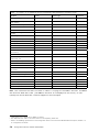


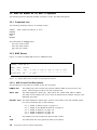


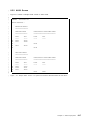
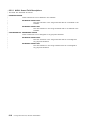
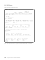


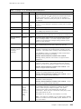
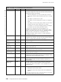

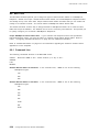
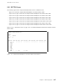
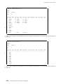

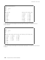
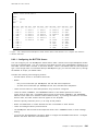
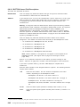
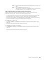
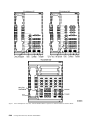
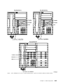
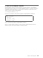
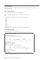
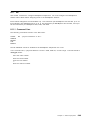
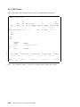


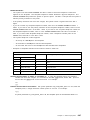

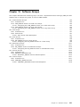


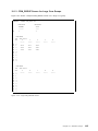


![mm [mm [1 um um [11115151116 |])|]1]](http://vs1.manualzilla.com/store/data/005839409_1-1dd2adaaab9a040f039445848c9c3135-150x150.png)