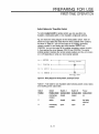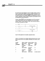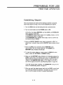
1
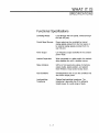
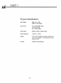
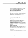
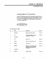
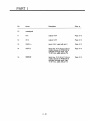
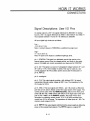
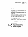
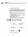
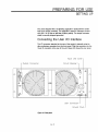
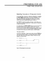
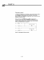
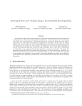
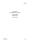
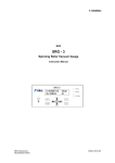
THE ADVANCED ENERGY® PE 5000 GENERATOR User Manual Serial Number: _ ADVANCED ENERGY INDUSTRIES, INC 1600 Prospect Parkway Fort Collins, Colorado 80525 (303) 221-4670 Telex #45-0938 PN: 5700209 March 1990 To ensure years of dependable service, Advanced Energy® products are thoroughly tested and designed to be among the most reliable and highest quality systems available worldwide. All parts and labor carry our standard 1-year warranty. For Customer Service, call: AE Colorado (303) 221-0108 (24-hour line) Fax: (303) 221-5583 AE California (408) 263-8784 (8 a.m. to 5 p.m. Pacific Standard Time California only) Fax: (408) 263-8992 AE Japan 81 (03) 222-1311 Fax: 81 (03) 222-1315 all others contact your local distributor - see the list on the next page ©1989, Advanced Energy Industries, Inc All rights reserved. Printed in the Un~ed States of America. This manual is supplied to enable the reader to safely install, operate, and service the equipment described herein. Making copies of any part of this manual for any purpose other than these is a violation of U.S. copyright law. In the interest of providing even better equipment, Advanced Energy Industries, Inc., reserves the right to make product changes without notification or obligation. For more information, write Advanced Energy Industries, Inc., 1600 Prospect Parkway, Fort Collins, CO 80525. AE Service Centers Company Name Phone/Fax Numbers VacutecAB Sweden 46 (0) 40-437270 Fax: 46 (0) 40-435538 Gambetti Kenologia snc Italy Fax: 39 (02) 9052778 Segen Technologies, Ltd. Israel 972 (03) 9363106 Fax: 972 (03) 9362030 Zeus Co., Ltd. Korea 82 (02) 577-3181 Fax: 82 (02) 576-3199 Schmidt Scientific Taiwan Fax: 886 (02) 25029692 39 (02) 9055660 886 (02) 5013468 Returning Units for Repair Before returning any product for repair and/or adjustment, call AE Customer Service and discuss the problem with them. Be prepared to give them the serial number of the unit and the reason for the proposed return. This consultation call will allow Customer Service to determine if the unit must actually be returned for the problem to be corrected. Such technical consultation is always available at no charge. If you return a unit without first getting authorization from Customer Service, and that unit is found to be functional, you will have to pay a retest and calibration fee, and all shipping charges. Upgrading Units AE will upgrade older units for a fee (a percentage of the current list price, based on the age of the unit. Such an upgraded unit will cany a 6-month warranty (which will be added to any time remaining on the original warranty). SAFETY WARNING SAFE OPERATING PROCEDURES AND PROPER USE OF THE EQUIPMENT ARE THE RESPONSIBILITY OF THE USER OF THIS SYSTEM. Advanced Energy Industries, Inc., provides information on ~s products and associated hazards, but it assumes no responsibility for the after-sale operation of the equipment or the safety practices of the owner or user. This equipment produces potentially lethal high-voltage, high-current, radio frequency (RF) energy. You should read this manual and understand ITS contents before you attempt to hook up or operate the equipment it describes. Follow all safety precautions. Never defeat interlocks or grounds. ~Y-O-U--- SHOULD KNOW••• DANGERI All personnel who work with or who are exposed to this equipment must take precautions to protect themselves against serious or possibly fatal bodily injury. DO NOT BE CARELESS AROUND THIS EQUIPMENT. CONGRATULATIONS On your purchase of AE's PE series generator, designed for hard use in a vacuum environment. Advanced circu~ design and calibrated instrumentation make these units the most accurate, most efficient, and most versatile in the world today. Since 1981, AE's power supplies and controllers have been contributing to a broad range of advanced technological processes such as semiconductor fabrication, optical coating, printed circuit manufacturing, glass coating, and data storage media plating. In the United States, Europe, and Asia, Advanced Energy Industries, Inc., is known for its quality products and strong customer support. CONTENTS INTRODUCTION Guide to Interpreting the Manual i PART I GETIING TO KNOW YOUR PE SERIES GENERATOR 1. WHAT IT IS General Description Specifications 1-5 1-7 2. HOW IT WORKS Theory of Operation Interfacing Connectors 2-3 2-5 2-9 PART II OPERATING YOUR PE SERIES GENERATOR 3. PREPARING FOR USE Setting Up First-time Operation 3-5 3-9 4. CHOOSING MODES Remote Control . . . . . . . . . . . . . . . . . . . . . . . . . . . . . . . . . 4-3 PART III SERVICING YOUR PE SERIES GENERATOR 5. CALIBRATION AND TROUBLESHOOTING 1. Calibration . . . . . . . . . . . . . . . . . . . . . . . . . . . . . . . . . . . 5-5 2. Troubleshooting 5-7 PART IV THE AE LOAD-MATCHING MODULE 6. LOAD MATCHING 1. General Description . . . . . . . . . . . . . . . . . . . . . . . . . . . . 6-5 2. Making Connections 6-7 WARRANTY Ll2~-------------------------- INTRODUCTION GUIDE TO INTERPRETING THE MANUAL Overview of the Manual The main table of contents is an outline of the major topics covered in the manual. It shows each chapter and the major sections of each chapter. It contains only the major sections so that you can skim ~ and get a general idea of what is contained here, without having to look at a lot of headings. In the manual, the chapter titles and the major sections are printed at the top right-hand corner of each odd-numbered page. When you turn to a chapter, you will find a detailed table of contents that lists each subheading in the chapter. This will show you which page contains the information you are looking for. Part 1, Getting to Know Your PE Series Generator, contains two chapters: What It Is and How It Works. What It Is gives an overview of the PE and a description of the functional and physical specifications. How It Works contains a functional block diagram, a description of the front panel controls and status indicators, and important information on connectors and signal descriptions. Part II, Operating Your PE Series Generator, also contains two chapters: Preparing for Use and Choosing Modes. Preparing for Use provides information on unpacking, connecting, and starting up your PEe Choosing Modes tells you how to select remote control. Part III, Servicing Your PE Series Generator, contains one chapter, Calibration and Troubleshooting. This chapter tells you how to adjust the PE and service minor problems. Part IV, The AE Load-matching Module, describes the load-matching module and tells you how to install it. Type Conventions To help you quickly pick out what is being discussed, the manual presents certain words and phrases in type that is different from the rest of the text. Pin and line names appear in capitalized italics (POWCOM). Labels that are on the PE (switches, indicators, etc.) generally appear in boldface capital letters (PLASMA). Functions are printed in boldface lowercase letters (on/off). dE8 ------------------------- PART I GETTING TO KNOW YOUR PE SERIES GENERATOR WHAT IT IS CONTENTS General Description . . . . . . . . . . . . . . . . . . . . . . . . . . . . . . . . . . . . 1-5 Understanding Switch-mode Operation Specifications 1-5 1-7 Functional Specifications Physical Specifications 1-3 1-7 . . . . . . . . . . . . . . . . . . . 1-8 1-4 WHAT IT IS GENERAL DESCRIPTION The PE series power supply is designed as a power source for plasma processes. The unit delivers power and holds power at the specified level during plasma variations. You can control the output and monitor the unit either from the front panel or through an I/O connector provided on the rear panel. PE series units easily interface with most logic types and both relay and switch contact closures. The PE series uses a resonant power conversion technique coordinated with a highly effective line fitter. This produces extremely efficient operation typical of switching power supplies while maintaining the low electromagnetic interference (EMI) of linear power supplies. Understanding Switch-mode Operation There are two basic approaches to ac power generation. The first, most common, is linear operation. The second, more recent development, is switch-mode operation. The following discussion explains the significant differences between the two types of operation. Both linear and switch-mode supplies use an input rectifier/fitter; however, linear supplies require a large 60-Hz step up/step down transformer. This transformer means that linear supplies are larger and heavier than switching supplies of the same power rating. Another significant difference between linear and switching power supplies of a given frequency is the control element. Linear supplies use transistors or tubes as variable resistors that gradually change their value in response to a control signal. This gradual change causes the supply to dissipate nearly as much (possibly more) heat as the load. If transistors are used, an additional problem called "secondary breakdown" is common. Secondary breakdown prevents full device use, so large numbers of devices must be combined to - produce the required power. In contrast, switch-mode supplies use transistors optimized for rapid "turn on" and "turn off" in series with the bad. Because each switch is always either fully on or off, switch-mode supplies dissipate significantly less power than do linear supplies. One drawback of using switching supplies with plasma processes is that a plasma requires a current or "energy" source for proper stabilization. Most switching supplies are voltage sources. 1-5 42 8 PART I - -- -- -- -- -- -- -- -- -- -- -- -- - The PE series deals with this problem in a unique fashion. First, a reactive power fi~er wkh a pass characteristic at the fundamental frequency acts as an energy source, The filter supplies both the voltage and current that the plasma requires for stability, and in addition, isolates transients (arcs, for example) from the generator. Because of the smoothing effect of the filter, the switches can be pulse-width modulated, and power control is attained with the same devices used for power generation. Hence the description, pulse-width modulated resonant inverter. 1-6 WHAT IT IS SPECIFICATIONS Functional Specifications Controlling Modes Local (through the front panel), remote (through the User I/O port).' Control Signal Sources Power output can be controlled by internal analog signals entered from the front panel, or by external analog signals provided from the user I/O port. Power Output Low frequency output controlled in the constant power mode. Interlock Supervision When connected to a safety switch, the interlock string disables the unit if a problem occurs. Status Indicators LED's on front panel show status of interlocks, output enable, plasma ignition, and setpoint level. Remote or local control is also shown. Fault Conditions Overtemperature and arc are the conditions that shut off the output power. Load-matching Transformer Optional load-matching transformer. The transformer's taps allow the PE to efficiently transfer power to a wide range of loads. 1-7 d2 8 PART I - -- -- -- -- -- -- -- -- -- -- -- -- - Physical Specifications Input 208 V ac ± 10% 50/60 Hz three phase Vo~age Input Current 15 A nominal (full power) 0.92 power factor 20 A circuit breaker Output Power 3000 W at 550 V nominal output Output Frequency 100 kHz ± 100 Hz Cooling 0° C to 45° C ambient; 9 inches of clearance to rear of unit required; 1 inch clearance on sides and top of unit 00/0-92 0/0, noncondensing Humidity 1-8 HOW IT WORKS CONTENTS Theory of Operation 2-3 Interfacing 2-5 Front Panel Controls 2-5 Status Indicators 2-7 Connectors 2-9 Analog/Digital I/O Connections 2-9 Signal Descriptions: User I/O Pins 2-11 2-1 PART I 2-2 HOW IT WORKS THEORY OF OPERATION The PE converts ac line power into rectified dc voltage. The dc votaue provides an unregulated source for high-frequency inverters. The inverters convert the unregulated dc voltage to high-frequency ac vottage. The following sections describe the functional units of the PE power supply. Figure 2-1 on page 2-4 shows the PE block diagram. Circuit Breaker/EMC Filter The circuit breaker located on the rear panel automatically protects the system wiring in the event of a failure. In some units a fuse is used instead of a circuit breaker. The internal EMC filter reduces the amount of high-frequency noise conducted to the power lines. Main Contactor/Rectifier The main contactor applies incoming ac voltage to the rectifier. The rectifier converts the ac input to unregulated dc voltage. Filter/Soft Start The input filter reduces EMI conducted at low frequencies. It also reduces the peak current through the rectifier and the dc fitter capacitor, and provides a stable input impedance for the dc-to-ac regulator. The soft start circuit prevents large surge currents when the input power is turned on. The circuit uses a 50 0 resistor to charge the dc filter capacitor and then shorts this resistor when the dc filter cap is charged to the normal operating level. Auxiliary Power Supply The auxiliary power supply is a 50/60 Hz transformer with an isolated 40 V ac center-tapped winding. The secondary winding generates ± 24 V dc to power the control electronics. Drive Board The drive board provides isolatlon between the control logic and the inverter. 2-3 PART I Inverter/Frequency Module/Output Transformer The inverter chops the dc voltage into a square wave ac voltage that passes through a series resonant circuit to produce a sine wave. This sine wave passes through an isolation (output) transformer. Output Sense The output sense converts and isolates output voltage and current to logic levels. Display/User I/O The display provides status information and control from the front panel. The user I/O port interface provides status and control for the remote interface. Logic The logic provides fault protection, on/off control, and power regulation. Input Line Unregulated 300 V de User I/O Figure 2-1. PEblock diagram. 2-4 HOW IT WORKS INTERFACING Front Panel Controls The switches described below provide complete control of the PE power supply from the front panel. Figure 2-2 on page 2-6 shows the front panel. POWER ON/OFF Applies line power to internal circuitry. OUTPUT ON/OFF OFF resets the interlocks and overtemperature fault and removes the output power. OFF resets in both local and remote modes. However, in remote mode, power remains off only as long as the switch is held off. ON enables power to be transferred to the output connector. ON works only in local mode. LEVEL Controls output power in local mode. Rotating the locking skirt clockwise locks the knob in position without changing the setpoint value. The control has 10 turns and 0.1 % resolution. REMOTE/LOCAL The two-position switch under the LEVEL knob selects remote or local control for the signal that programs power level. The two-position switch located under OUTPUT ON/OFF switch selects remote or local control for enabling the output. DISPLAY A momentary toggle switch that selects values to read on the MONITOR display. The middle or neutral position displays power in kilowatts. The upper and lower positions display voltage and current, respectively. Analog values of these signals are continuously available at the rear 1/0 connector. 2-5 PART I 0 0 [ 0 o o o £W~T PlASMA OUlPUT IN1£RLOCK L\E~ STATUS o o o o MONITOR ARC O'JERlDAP REMOTE LOCAL POWER OUlPUT DISPLAY ON ON VOLTAGE E3 B OfF CURRENT ~ OfF LOCM. REM01E @) Igr I i ][ 0 LEVEL 0 LOCAL REMOTE @) Figure 2-2. PE front panel. 2-6 0 PE 5K AC PLASMA POWER SOURCE HOW IT WORKS INTERFACING Status Indicators The PE power supply can be monitored by checking the following STATUS indicators on the front panel. INTERLOCK Lights· when all interlocks are satisfied. Flashes when the interlock chain is broken. Unlit when the remote I/O connector is not in, the OUTPUT OFF momentary rocker position is actuated, or the remote XOFF.D command is active (high). OUTPUT Lights when the main contactor is closed, and the output is enabled and ready to deliver power. PLASMA Lights when over 1% of the full-scale output current has been reached (indicates plasma ignition). SETPOINT Lights when output power is within 0.20/0 of setpoint level. Flashes when there is a plasma indicated, but output power is further than 0.2% from setpoint level. Unlit when no plasma is present. LOCAL Lights to indicate unit is controlled through front panel. REMOTE Lights to indicate unit is being controlled through user I/O port. OVERTEMP Flashes when the temperature of the unit exceeds the factory-set limit. This turns off the unit until the temperature sensor cools and the supply is reset by setting the OUTPUT ON/OFF switch momentarily to OFF. Unlit when the operating temperature is normal. 2-7 PART I Lights when an arc or an abnormally low process impedance occurs. The supply turns off within 1 ms after sensing this condition, withdraws the energy from the output power components, and in 3 ms reapplies power. The ARC indicator lights for 1 sec. after this event is sensed. ARC 2-8 HOW IT WORKS CONNECTORS Analog/Digital I/O Connections The user 110 interface uses the 15-pin, D subminiature, insulated connector shown below. The Pin-description Table gives a brief description of each pin, for a more detailed discussion see the page number referenced with each pin. Note: An ".A" appended to a pin name indicates an analog signal; a ".D" indicates a digital signal. © 1 2 3 4 5 6 7 8 00000000 0000000 9 10 11 12 13 14 15 © Pin-description Table Pin Name Description Refer to POWCOM digital and control common Page 2-11 2 24V can be either digital or analog, unregulated 24-V supply Page 2-11 3 unassigned 4 XV.A output, 0-5 V Page 2-11 5 XSIG.A- input, 0-5 V, used with 6 XSPT.D output, 0-15 V Page 2-11 7 INTLK.D input, low -15 V dc to 3 V dc (a contact closure to POWCOM is sufficient low-logic level), high 11-30 V dc Page 2-12 8 unassigned 9 SIGCOM analog common Page 2-12 2-9 pin 13 Page 2-11 PART I Description Refer to XI.A output, 0-5 V Page 2-12 12 XP.A output, 0-5 V Page 2-12 13 XSIG.A+ input, 0-5 V, used with 14 XOFF.D input, low -15 V dc to 3 V dc (a contact closure to POWCOM is sufficient low-logic level), high 11-30 V de, used w~h pin 15 Page 2-13 15 XSON.D input, low -15 V dc to 3 V dc (a contact closure to POWCOM is sufficient low-logic leveO, high 11-30 V de, used with pin 14 Page 2-13 Pin Name 10 unassigned 11 2 - 10 pin 5 Page 2-12 HOW IT WORKS CONNECTORS Signal Descriptions: User I/O Pins An analog output is a 0-5 V dc signal referenced to SIGCOM. An analog input is a 0-5 V dc signal referenced to XSIG.A-. Both XSIG.A- and XSIG.A+ must operate between 0 V and 10 V in reference to SIGCOM. All input digital logic levels are as follows: Low --15 V de to 3 V de Note: A contact closure to POWCOM is a sufficient low-logic level. High-11 V dc to 30 V dc Note: An open to the inputs is a sufficient high-logic level. pin 1. POWCOM. This signal is a dedicated ground that returns to the internal system ground, then the chassis ground, and finally to the safety ground. All digital and control connections are referenced to POWCOM. pin 2. 24V. This signal is a source of unregulated voltage between 22 V and 35 V with a 1/4 W, 100 Q resistor in series. This may be used as a low current (maximum 50 mA) auxiliary power source (see the discussion of pin 6, XSPT. D). pin 3. unassigned pin 4. XV.A This output signal provides a fully buffered 0-5 V dc signal representing full-scale output voltage at 600 V rms. The impedance of the XV:A output is 100 Q. pin 5. XSIG.A- This input signal and XSIG.A + (pin 13) provide a differential pair that can be used to linearly control the output power of the supply. This control point is active when the REMOTE/LOCAL sw~ch on the front panel (units built after Feb. 1989) OR the DIP switch on the logic board (units built prior to Feb. 1989) is in the REMOTE position. See page 4-3 for more information on selecting remote control. A 0-5 V dc input provides linear control from 0 W to full power. The impedance of these inputs is 1 MO. The common mode range is 0-10 V. pin 6. XSPT.D This output signal confirms that the power supply is delivering power at the programmed setpoint. The XSPT.D output is a signal FET 2 - 11 PART I switch referenced to POWCOM. The switch will "sink" 500 mA to drive most relays and will withstand 60 V open circuit. There is a 1-W, 57-V zener diode from the XSPT.D connection to POWCOM; this zener absorbs relay energy and protects the FET. An alternative is to place a resistor (5 kQ minimum) between pin 2 and XSPT.D to develop a logic output. pin 7. INTLK.D This input signal is a secondary off command that disables the unit in the event of a high logic level in the interlock line. The interlock line is typically connected by the user to a safety swtch, or a series of safety swtches, referred to as an interlock string. These switches protect people, process, and equipment. With the interlock string incomplete, the power supply's main contactor will not close. If the contactor is closed, and interlock is broken, the output power is disabled within 1 ms. On the PE front panel an INTERLOCK status indicator flashes when the interlock string is broken. To reset the INTERLOCK indicator, the interlock must be satisfied. Circuit Specifications The interlock circuitry has an internal 10 kQ pull-up resistor to 15 V. pin 8. unassigned pin 9. S/GCOM. This signal is a dedicated ground that returns to the internal system ground, then the chassis ground, and finally to the safety ground. All analog connections are referenced to SIGCOM. pin 10. unassigned pin 11. XI.A This output signal provides a fully buffered 0-5 V dc signal representing full-scale output current of 6 A. The output impedance of the XI.A output is 100 Q. pin 12. XP.A This output signal provides a fully buffered 0-5 V dc signal representing full-scale output power. The output impedance of the XP.A output is 100 Q. pin 13. XS/G.A + This input signal and XSIG.A- (pin 5) provide a differential pair that can be used to linearly control the output power of the supply. This control point is active when the REMOTE/LOCAL swtch on the front panel (units built after Feb. 1989) OR the DIP switch on the logic board (units built prior to Feb. 1989) is in the REMOTE position. See page 4-3 for more information on selecting remote control. A 0-5 V dc input provides linear 2 - 12 HOW IT WORKS CONNECTORS control from 0 W to full power. The impedance of these inputs is 1 MO. The common mode range is 0-1 0 v. pin 14. XOFF.D This input signal duplicates the OFF function of the front panel OUTPUT ON/OFF switch. A high logic level overrides all other commands and forces the output off, opening the main contactor, and resetting any interlock or overtemperature faults. Circuit Specifications The XOFF.D circuitry has an internal 10 kQ pull-up resistor to 15 V. Circuit delay is less than 1 ms. While XOFF.D is active, only the REMOTE or LOCAL status indicator will light. pin 15. XSON.D This input signal replaces the ON function of the front panel OUTPUT ON/OFF switch when the REMOTEILOCAL switch on the front panel (units built after Feb. 1989) OR the DIP switch on the logic board (units built prior to Feb. 1989) is in the REMOTE position. See page 4-3 for more information on selecting remote control. A low logic level turns the supply on. XOFF.D must be low for XSON.D to be active. For information on two-pin and three-pin wiring, see page 3-9. Circuit Specifications The XSON.D circuitry has an internal 10 kQ pull-up resistor to 15 V. While XSON.D is active, the main contactor remains closed, and the front panel OUTPUT status indicator lights. 2 - 13 PART I 2 - 14 PART II OPERATING YOUR PE SERIES GENERATOR d2 8 PART II PREPARING FOR USE CONTENTS Setting Up . . . . . . . . . . . . . . . . . . . . . . . . . . . . . . . . . . . . . . . . . . . 3-5 Unpacking 3-5 Connecting Input Power 3-5 Connecting Output Power . . . . . . . . . . . . . . . . . . . . . . . 3-6 Connecting the User I/O Interface First-time Operation 3-7 3-9 Selecting Two-wire or Three-wire Control 3-9 Establishing Setpoint 3-13 3-3 3-4 PREPARING FOR USE SETTING UP Unpacking Unpack and inspect your power supply carefully. Check for obvious physical damage to the exterior of the unit, and then remove the six phillips screws on the top cover of the supply. Remove the top sheet metal to uncover the plexiglass safety shield. Without removing the safety shield, check for obvious signs of physical damage to the interior of the unit. If no damage is apparent, reinstall the top sheet metal cover and proceed with the unit connections. If you do see signs of shipping damage, contact Advanced Energy Industries, Inc., and the carrier immediately. Save the shipping container for submitting necessary claims to the carrier. Connecting Input Power The PE 5000 requires 208·V, three-phase, 50/60 Hz input power with either a wye or delta connection. Three-phase rotation is not important. To conned the input, place the input circuit breaker in the OFF position and attach the line cord to the 208-V, three-phase with ground. Attach the ground stud (next to power cord) to the system ground with at least 14 gauge, stranded wire. ~-YO-U-"" SHOULD KNOW••• Once the connections are complete, lethal voltages are potentially present at the output connector. Be sure this connector is terminated and follow normal safety precautions when the system is operating. 3-5 PART II dE-(!)-------------------------- Connecting Output Power The main power output connector requires a standard HN plug. A typical combination is an Amphenol part #83-804 (Mil UG59B) and RG-8 cable or Amphenol part #8125 (Mil UG494) and RG 217 cable. There is no practical limit to the length of the cable. Use the following instructions to prepare the cable: 1. Strip the cable; be careful not to nick the braid, the dielectric, or the conductor. 2. Slip end "A", insulator "B", washer "C", and cone "0" onto the cable. Push cone "C" all the way onto the outer insulation. Cut the braided shield 0.25 in. from the cone. 3. Roll the braided shield back over cone "0". Cut the inner insulation and the center conductor to the dimensions shown. 4. Solder the tip to the center conductor. 5. Attach the outer cover. 6. Conduct a high-potential test for the insulation. Hi-pot the insulation to 3 kV dc between the center conductor and the outside shield. ~-YO-U--- SHOULD KNOW••• When conducting a high-potential test, high voltages are present. Use extreme caution. 1 1 CD p'---_----J• ~ .25 035 ® I 1.25 . , 1r . ; .75 B C 0 ~ ~ ...... .25 L ® Figure 3-1. Preparing the RG-B coaxialcable. 3-6 A ...... ...... @) CE]::1> PREPARING FOR USE SETIING UP The unit is shipped with a dc-blocking capacitor in series with the center lead of the output connector. The capacitor is rated for full-output current and 400 V of de bias or self bias of either polarity. The output connector shield is normally shipped grounded. Connecting the User I/O Interface The I/O connector attached to the rear of the supply is internally wired to allow preliminary operation from the front panel. Plug this connector into the 1S-pin 0 connector at the rear of the unit. Figure 3-2 shows the rear panel. Input Line Cord Output Connector Circuit Breaker 8 @ 0 ~ 0 @ @ @ @ @@ @@ @ CY 0 @ @ V':A:A~I'~~A~,:I @ e @ User Connector Ground Stud Figure 3-2. Rearpanel. 3-7 0 3-8 PREPARING FOR USE FIRST-TIME OPERATION Selecting Two-wire or Three-wire Control You can select either a two-wire or a three-wire configuration for controlling the output on/off in remote mode. In the two-wire configuration, XOFF.D (pin 14) and XSON.D (pin 15) function as one input; in the three-wire configuration they function independently. For information on selecting remote mode, see the Choosing Modes section on page 4-3. Both XSON.D and XOFF.D are pulled up through a 10 kQ resistor, so an open circuit is a sufficient high-logic level. A contact closure to POWCOM is a sufficient low-logic level. As a safety feature, the OUTPUT ON/OFF switch on the front panel will turn the output off while the unit is operating in remote mode. If you use three-wire control, the output remains off until you turn it on again. However, if you use two-wire control, the front panel OUTPUT ON/OFF switch keeps the output off only as long as you hold the switch in the OFF position. Two-wire control In a two-wire configuration, a closed contact switch pulls both XSON.D and XOFF.D low and turns the output on. An open switch pulls both XSON.D and XOFF.D high and turns the output off. Figure 3-3 shows the wiring diragram for two-wire control. Pin 1 POWCOMo~-----, Pin 7 INTLK.D Pin 14 XOFF.Do-~--->----------------' Pin 15 XSON.Do-~------' Figure 3-3. Wiring diagram for two-wire control 3-9 d28 PART II - - - -..........................- - - - - - - - - - - - - - - - - - - - Three-wire control In a three-wire configuration, the momentary contact switch between XOFF.D and POWCOM is normally closed and the momentary contact switch between XSON.D and POWCOM is normally open. Fig. 3-4 shows the wiring diragram for three-wire control. When you first turn the POWER switch to ON, the output is off; a momentary contact closure between XSON.D and POWCOM turns the output on. When the output is on, a momentary open contact between XOFF.D and POWCOM turns the output off. Pi n 7 INTLK.D o :- --iIIIl-----------------, Normally Closed Pi n 1 POWCOMo-:---4.---------0 Pin 14 XOFF.D 0------. :0------------------' Normally Open Pin 15 XSON.D ...L:0----.---1 Of----------O Figure 3-4. Wiring diagram for three-wire control. 3 - 10 PREPARING FOR USE FIRST-TIME OPERATION Switch Options for Three-Wire Control To control output on/off in remote control, you can use either one 3-position, double-pole swkch, or two z-poston, single-pole switches. Fig. 3-5 shows the wiring diagram for the three-position switch. Table 3-1 shows the output states that result from the three possible switch positions. As shown in Table 3-1, you turn the output on by making momentary contact at switch B, thus closing the circuit between XSON.D and POWCOM. You turn the output off by making momentary contact at switch A, thus opening the circuit between XOFF.D and POWCOM. The stable (middle) poston maintains the normal contact positions and the unit remains on or off depending on what you most recently selected. Pin 7 INTLK.D Normally Closed A Pin 1 POWCOM Pin 14 XOFF.D Pin 15 XSON.D I 1- o ~ - - - - - - - - - ~ o0 - - - - - - - - - - ' Normally Open B Figure 3-5. Wiring diagram for three-position, double-pole switch. Table 3-1. Truth table for one 3-position swtch showing switch contact states and resutting power output state. Swkch Position Switch A Swkch Swkch B Power Position State Contact State Contact State Output State 1 momentary contact closed closed on 2 stable closed open last state selected 3 momentary contact open open off 3 - 11 dE:_ 8 PART II - - -. . . . . . . . . . . . . . . . . . . .- - - - - - - - - - - - - - - - - - - - - - - - - - - - Fig. 3-6 shows the wiring diagram for the two 2-position switches. Table 3-2 shows the output states resulting from the four possible combinations of the swtch position states. As with the three-position switch, momentary contact at switch B closes the circu~ between XSON.D and POWCOM and turns the output on. Momentary contact at switch A opens the circu~ between XOFF.D and POWCOM and turns the output off. However, pulling XSON.D low turns the output on only if the momentary contact switch between XOFF.D and POWCOM is in its normal position (closed). Therefore, if both switches are held in their momentary positions, the off swtch overrides the on swtch, Pin 7 INTLK.D Normally Closed Pin 1 POWCOM Pin 14 XOFF.D Normally Open Pin 15 XSON. D ..L O~----------.jO 0---------' B Figure 3-6. Wiring diagram for two 2-position, single-pole switches. Table 3-2. Truth table for two 2-position swtches showing the power output states that result from the four possible combinations of the switch contact states. Possible Switch Combination Switch A Position Switch B Position Power State (Contact State (Contact Output State) State) Sta1EL momentary stable (open) off (open) 2 stable (closed) momentary (closed) on 3 momentary (open) momentary (closed) off 4 stable (closed) stable (open) last state selected 3 - 12 PREPARING FOR USE FIRST-TIME OPERATION Establishing Setpoint After all connections are made and the discharge chamber is prepared, follow these steps for turning on the un~ and establishing the setpoint: 1. Turn the LEVEL knob and the locking skirt fully counterclockwise. 2. Turn the circuit breaker and the POWER switch to ON. At this time, the display MONITOR, and the LOCAL and INTERLOCK status indicators should light. If the REMOTE indicator lights instead of the LOCAL indicator, see the Troubleshooting section on page 5-7. If the INTERLOCK status indicator fails to light, check to confirm that the interlock string is satisfied. 3. Move the OUTPUT ON/OFF rocker switch momentarily to ON. You should hear a contactor close, and the OUTPUT status indicator should light. 4. Move the LEVEL knob clockwise until the MONITOR reads approximately 10% of full output (300 W). The PLASMA and SETPOINT status indicators should light. 5. To check the output voltage or current, move the DISPLAY rocker switch to either the VOLTAGE or CURRENT setting. 6. Make sure the SETPOINT status indicator is lit. Gradually advance the LEVEL control knob to the desired power level. If the SETPOINT light flashes before the desired power level is reached, check the output voltage on the MONITOR LED display. If the voltage is over 600 V, turn off the supply and see the Load Matching section on page 6-5. If the ARC indicator light is flashing, turn POWER OFF, and go to the see the Troubleshooting section on page 5-7. 7. When you reach the desired power level, lock the LEVEL control knob by turning the locking skirt clockwise. The supply can be turned off and on, and the power will return to setpoint automatically. 3 - 13 d2- PART II 3 - 14 CHOOSING MODES CONTENTS Remote Control '. . 4-3 Selecting Remote Control . . . . . . . . . . . . . . . . . . . . . . . 4-3 Units built prior to 2/6/89 4-3 Units built after 2/6/89 4-3 4-1 dEe EMil.JJ __ 4-2 CHOOSING MODES REMOTE CONTROL Selecting Remote Operation For units built prior to 2/6/89 1. Before removing the plastic safety shield, turn off the supply and let it stt for 5 min. before beginning work. 2. Unscrew the six phillips screws from the top of the power supply and remove the metal cover. 3. Remove the plastic plexiglass safety shield. 4. Three small DIP switches will be visible on the logic board (with the supply facing forward, the logic board faces the front of the supply). The left switch controls the output on/off, the middle switch controls the REMOTE and LOCAL indicators on the STATUS display, and the right switch controls the signal source for programming power level. "Up" or C1 is for local operation and "down" or C2 is for remote operation. The DIP switches may be set in any combination. After adjusting the switches, replace the plexiglass cover. For units built after 2/6/89 1. Turn the OUTPUT ON/OFF switch OFF. 2. For remote operation of the output power, use a standard screwdriver to rotate the adjustable switch located directly under OUTPUT ON/OFF switch on the front panel to REMOTE. 3. For remote operation of the signal for programming power level, rotate the switch located directly under the LEVEL knob on the front panel to REMOTE. If either of the LOCAUREMOTE switches are in the REMOTE position, the LOCAL indicator light in the STATUS display turns off and the REMOTE indicator lights. 4-3 d2 8 EABIJJ...... __ 4-4 PART III SERVICING YOUR PE SERIES GENERATOR CALIBRATION AND TROUBLESHOOTING CONTENTS Calibration 5-5 Removing the Top Cover of the Supply 5-5 Zeroing the Display Monitor 5-5 Maximum Power 5-5 Troubleshooting 5-3 5-7 d2 8 PART III 5-4 CALIBRATION AND TROUBLESHOOTING CALIBRATION Removing the Top Cover of the Supply Unscrew the six phillips screws from the top of the power supply and remove the metal cover. Zeroing the Display Monitor The screws used to make the zeroing adjustment are accessible through the holes in the plexiglass cover. P ZERO = Power Monitor; V ZERO = Vottage Monitor; I ZERO = Current Monitor 1. Before making any zeroing adjustments, turn the POWER ON/OFF switch to ON, turn the OUTPUT ON/OFF switch to OFF, and remove the metal cover. Leave the plexiglass cover in place and let the supply sit for at least 3 min. 2. For each value, turn the appropriate screw adjustment using a small standard screwdriver until the front panel display monitor reads zero. 3. Replace the top cover and the six screws. Maximum Power The maximum power adjustment clamps the output power to a predetermined limit, independent of local or remote programming. The MAX PWR potentiometer is accessible through the holes on the plexiglass cover. 1. Using the LEVEL knob on the front panel or the appropriate user I/O signal to set the power to just above the maximum desired operating level. 2. While operating at this level, turn the control MAX PWR potentiometer counterclockwise until the displayed power is at the desired clamp point. 5-5 d2- PART III 5-6 CALIBRATION AND TROUBLESHOOTING TROUBLESHOOTING Troubleshooting Guide Lh. y-O-U-....• 'llllIIII. SHOULD KNOW••• All servicing functions involving input and output connections can expose you to lethal voltages. Make sure you take proper safety precautions before you troubleshoot the power supply. These troubleshooting suggestions are included for your convenience. They are only intended to deal with minor problems. If these troubleshooting tips fail to correct problems w~h the operation of the power supply, please contact the Advanced Energy Industries, Inc. Customer Service Department at: (303) 221-4670 or at AE's 24 hour service hotline: (303) 221-01 08 Symptom Things To Check/Remedy No front panel lights Make sure the input power cord is connected to appropriate power source. See the Connecting Input section on page 3-5 for appropriate power source/requirements. Make sure the circuit breaker on the rear of the power supply is ON. Make sure the front panel POWER switch is ON. No STATUS lights except REMOTE or LOCAL. Make sure the I/O connector on the rear panel is connected. Make sure the pin connections for the I/O plug are correct. See page 2-13 for an explanation of XOFF (pin 14). 5-7 d28 PART III - - - .. . . . . . . . . . . . . . . . . . . .- - - - - - - - - - - - - - - - - - - INTERLOCK light is flashing. Check to see if interlock string is complete. If not, see page 2-12 (pin 7) for an explanation of the interlock string requirements. Output of power supply won't turn on. Check the first two troubleshooting suggestions (No front panel lights and No STATUS lights except REMOTE or LOCAL). If output still won't come on, make sure the REMOTE/LOCAL status indicators on front panel are in the desired positions. See the Remote Control section on page 4-3. No PLASMA indication on 5TATU5 display. Make sure the output cable is attached to the rear of the supply. Make sure the vacuum system is at desired pressure. Make sure the correct power level is programmed into the supply. If not, use the LEVEL knob or user 1/0 interface to set the power level to the desired setpoint. See the First Time Operation section beginning on page 3-9. Verify the voltage output indicated on the MONITOR display. Cannot achieve desired power level, but neither the ARC or SETPOINT indicators on STATUS display are flashing. Make sure the maximum power adjustment is set correctly. See the Maximum Power section on page 5-5. Cannot achieve full output power and ARC and SETPOINT indicators on STATUS display are flashing. Disconnect output cable from power supply and enable the output. If the ARC indicator is still flashing, call AE Customer Service. Check the system or chamber for low impedance to ground. If a low impedance to ground is present, the problem must be corrected before the supply will function properly. 5-8 CALIBRATION AND TROUBLESHOOTING TROUBLESHOOTING Reconnect the power supply to the system. Turn OUTPUT switch ON. If the ARC indicator is still flashing, lower the power level by 200/ 0 . After lowering the power level, if the ARC indicator is no longer flashing, see the Load Matching section on page 6-7. If the ARC indicator is still flashing, call AE Customer Service. Cannot achieve full power and SETPOINT indicator on STATUS display is flashing. Move the DISPLAY switch on the front panel to VOLTAGE. If the voltage displayed on the MONITOR is above 600 V or below 500 V see the Load Matching section on page 6-7. If the voltage is between 500 V and 600 V, call AE Customer Service. OVERTEMP indicator on Make sure fans are operating and not STATUS display is flashing. blocked. Turn the supply off and call AE Customer Service. 5-9 d2 8 PART III 5 - 10 PART IV TH E AE LOAD-MATCH ING MODULE LOAD MATCH ING CONTENTS General Description 6-5 Making Connections . . . . . . . . . . . . . . . . . . . . . . . . . . . . . . . . . . . 6-7 6-3 6-4 LOAD MATCHING GENERAL DESCRIPTION Load Matching The load-matching modules used with PE series power supplies are designed as vottage transformers that correctly match the voltage of the power supply to the vottage requirement of the load. At a given power level and pressure, plasma operates at a fixed vottage level much like back-to-back zener diodes. Load matching is required when this voltage is not in the operating range of the power supply. Advanced Energy Industries, Inc., load-matching networks consist of a mud-tap auto transformer in a separate load-matching module. The load-matching module can handle the full rated power output of the associated power supply. It is possible to set up the load-matching module in a voltage step-up or voltage step-down configuration. This capability of stepping-up or stepping-down the supply's output voltage provides increased flexibility. All AE load-matching modules have dc voltage blocking capacitors in series with the input and the output. These capacitors protect the power supply from excessive dc vo ttages, which are often present in processes due to the gas type and/or the configuration of the electrodes. 6-5 6-6 LOAD MATCHING MAKING CONNECTIONS Connecting the Load-matching Module ~-YO-U-~·""'· SHOULD KNOW••• There is a high voltage potential at both the load-matching and the power supply connection points. Exercise extreme caution when working with this equipment. Do not make tap changes to load-matching modules while the unit's output power is on. Applying output power while changing tap settings will damage the load-matching module. Proper load matching can be accomplished by completing the following procedures: 1. Connect the power supply directly to the load without the load-matching module. 2. Turn the POWER ON/OFF and OUTPUT ON/OFF switches both ON. Slowly turn the LEVEL knob clockwise until MONITOR display shows the desired operating power level. Then increase the power an additional 100/ 0 . 3. If the SETPOINT indicator light is not flashing at this power level a load-matching module is not required. 4. If the SETPOINT indicator light is flashing, a load-matching module is required. If you have a LM-5K or LM-10K A: Attach the power supply to the terminal on the load-matching module labled SUPPLY and the load to the terminal labeled LOAD. If you have a LM-1.5K, LM-2.5K, or LM-5KA: Read the voltage level on the MONITOR display by moving the DISPLAY switch to VOLTAGE. 6-7 d2 8 PART IV __ If the voltage is above 600 V, connect the load-matching module in the step-up mode by attaching the power supply to the SUPPLY/STEP UP terminal and the load to the LOAD/STEP UP terminal. If the voltage is below 500 V, then connect the load matching module in the step-down mode by attaching the power supply to the SUPPLY/STEP DOWN terminal and the load to the LOAD/STEP DOWN terminal. Note: It is important to remember that the load matching module is designed to match the voltage of the supply to the voltage of the load. Therefore. the operating range of the power supply at full power is 520 V to 580 V. 5. Select tap 1 on the load match module. 6. Check the voltage on the MONITOR display. If the voltage is between 520 V and 580 V, then tap 1 is the appropriate tap. If the voltage is not in this range, turn the power supply OFF, change to tap 2 on the load match module, and repeat this process (up to tap 7, if necessary) until the voltage displayed in the MONITOR display is between 520 V and 580 V. Once the appropriate tap has been selected for delivering full power into a given process, that tap can be used from zero to full power. 6-8 W8IT8I1ty Claims Advanced Energy® products are warranted to be free from failures due to defects in material and workmanship for 12 months after they are shipped from the factory (please see warranty statement, below, for details). In order to claim shipping or handling damage, you must inspect the delivered goods and report such damage to AE within 30 days of your receipt of the goods. Please note that failing to report any damage within this period is the same as acknowledging that the goods were received undamaged. For • • • a warranty claim to be valid, it must: be made within the applicable warranty period include the product serial number and a full description of the circumstances giving rise to the claim have been assigned a return authorization number (see below) by AE Customer Service All warranty work will be performed at an authorized AE service center (see list of contacts at the front of the manual). You are responsible for obtaining authorization (see details below) to return any defective units, prepaying the freight costs, and ensuring that the units are returned to an authorized AE service center. AE will return the repaired unit (freight prepaid) to you by second-day air shipment (or ground carrier for local returns); repair parts and labor will be provided free of charge. Whoever ships the unit (either you or AE) is responsible for properly packaging and adequately insuring the unit. Authorized Returns Before returning any product for repair and/or adjustment, call AE Customer Service and discuss the problem with them. Be prepared to give them the serial number of the unit and the reason for the proposed return. This consultation call will allow Customer Service to determine if the unit must actually be returned for the problem to be corrected. Such technical consultation is always available at no charge. Units that are returned without authorization from AE Customer Service and that are found to be functional will not be covered under the warranty (see warranty statement, below). That is, you will have to pay a retest and calibration fee, and all shipping charges. ~rading_U_n_it_s _ AE's products are continually changing as ways to improve them are discovered. AE is happy to upgrade older units so that they reflect recent improvements. The fee for upgrading a unit will be a percentage of the current list price, based on the age of the unit. Such an upgraded unit will carry a 6-month warranty (which will be added to any time remaining on the original warranty). Contact Customer Service for specifics on getting an older unit upgraded to the current revision level. Warranty The seller makes no express or implied warranty that the goods are merchantable or fit for any particular purpose except as specifically stated in printed AE specifications. The sole responsibility of the Seller shall be that it will manufacture the goods in accordance with its published specifications and that the goods will be free from defects in material and workmanship. The seller's liability for breach of an expressed warranty shall exist only if the goods are installed, started in operation, and tested in conformity with the seller's published instructions. The seller expressly excludes any warranty whatsoever concerning goods that have been subject to misuse, negligence, or accident, or that have been altered or repaired by anyone other than the seller or the seller's duly authorized agent. This warranty is expressly made in lieu of any and all other warranties, express or implied, unless otherwise agreed to in writing. The warranty period is 12 months after the date the goods are shipped from AE. In all cases, the seller has sole responsibility for determining the cause and nature of the failure, and the seller's determination with regard thereto shall be final. AE, World Headquarters 1625 Sharp Point Drive Fort Collins, CO. 80525 USA Phone: 970.221.0108 or 970.221.0156 Fax: 970 .:221.5583 Email: [email protected] .\ ;:: ADVANCED £.l.. ENERGY