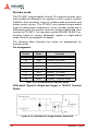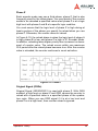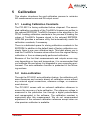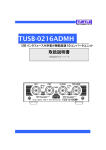
1
NuDAQ® PCI-9221
16-bit High-Resolution and
Multi-function DAQ Card
User’s Manual
Manual Rev.
2.00
Revision Date:
February 15, 2007
Part No:
50-11145-1000
Advance Technologies; Automate the World.
Copyright 2007 ADLINK TECHNOLOGY INC.
All Rights Reserved.
The information in this document is subject to change without prior
notice in order to improve reliability, design, and function and does
not represent a commitment on the part of the manufacturer.
In no event will the manufacturer be liable for direct, indirect, special, incidental, or consequential damages arising out of the use or
inability to use the product or documentation, even if advised of
the possibility of such damages.
This document contains proprietary information protected by copyright. All rights are reserved. No part of this manual may be reproduced by any mechanical, electronic, or other means in any form
without prior written permission of the manufacturer.
Trademarks
NuDAQ, NuIPC, DAQBench are registered trademarks of ADLINK
TECHNOLOGY INC.
Product names mentioned herein are used for identification purposes only and may be trademarks and/or registered trademarks
of their respective companies.
Getting service
Customer satisfaction is our top priority. Contact us should you
require any service or assistance.
ADLINK TECHNOLOGY INC.
Web Site
Sales & Service
Telephone No.
Fax No.
Mailing Address
http://www.adlinktech.com
[email protected]
+886-2-8226-5877
+886-2-8226-5717
9F No. 166 Jian Yi Road, Chungho City,
Taipei Hsien 235, Taiwan, ROC
ADLINK TECHNOLOGY AMERICA, INC.
Sales & Service
Toll-Free
Fax No.
Mailing Address
[email protected]
+1-866-4-ADLINK (235465)
+1-949-727-2099
8900 Research Drive, Irvine,
CA 92618, USA
ADLINK TECHNOLOGY EUROPEAN SALES OFFICE
Sales & Service
Toll-Free
Fax No.
Mailing Address
[email protected]
+49-211-4955552
+49-211-4955557
Nord Carree 3, 40477 Düsseldorf, Germany
ADLINK TECHNOLOGY SINGAPORE PTE LTD
Sales & Service
Telephone No.
Fax No.
Mailing Address
[email protected]
+65-6844-2261
+65-6844-2263
84 Genting Lane #07-02A,
Cityneon Design Center, Singapore 349584
ADLINK TECHNOLOGY INDIA LIAISON OFFICE
Sales & Service
Telephone No.
Fax No.
Mailing Address
[email protected]
+91-80-57605817
+91-80-26671806
No. 1357, Ground Floor, "Anupama",
Aurobindo Marg JP Nagar (Ph-1)
Bangalore - 560078
ADLINK TECHNOLOGY BEIJING
Sales & Service
Telephone No.
Fax No.
Mailing Address
[email protected]
+82-2-20570565
+82-2-20570563
4F, Kostech Building, 262-2,
Yangjae-Dong, Seocho-Gu,
Seoul, 137-130, South Korea
ADLINK TECHNOLOGY BEIJING
Sales & Service
Telephone No.
Fax No.
Mailing Address
[email protected]
+86-10-5885-8666
+86-10-5885-8625
Room 801, Building E, Yingchuangdongli
Plaza, No.1 Shangdidonglu,
Haidian District, Beijing, China
ADLINK TECHNOLOGY SHANGHAI
Sales & Service
Telephone No.
Fax No.
Mailing Address
[email protected]
+86-21-6495-5210
+86-21-5450-0414
Floor 4, Bldg. 39, Caoheting Science and
Technology Park, No.333 Qinjiang Road,
Shanghai, China
ADLINK TECHNOLOGY SHENZHEN
Sales & Service
Telephone No.
Fax No.
Mailing Address
[email protected]
+86-755-2643-4858
+86-755-2664-6353
C Block, 2nd Floor, Building A1,
Cyber-tech Zone, Gaoxin Ave. 7.S,
High-tech Industrial Park S.,
Nanshan District, Shenzhen,
Guangdong Province, China
Using this manual
1.1 Audience and scope
This manual guides you when using ADLINK NuDAQ® multi-function PCI card. The card’s hardware, signal connections, and calibration information are provided for faster application building.
This manual is intended for computer programmers and hardware
engineers with advanced knowledge of data acquisition and highlevel programming.
1.2 How this manual is organized
This manual is organized as follows:
Chapter 1 Introduction: This chapter intoduces the NuDAQ®
PCI-9221 card including its features, specifications, software
support information, and package contents.
Chapter 2 Hardware Information: This chapter presents the
card’s layout and connector pin definition.
Chapter 3 Installation: This part describes the PCI-9221
installation, configuration, and options for signal connections.
Chapter 4 Operation Theory: The operation theory of the
PCI-9221 functions including A/D conversion, D/A conversion,
and programmable function I/O are discussed in this chapter.
Chapter 5 Calibration: The chapter offers information on how
to calibrate the PCI-9221 for accurate data acquisition and output.
Appendix: The Appendix contains information on ADLINK
components that are recommended for use with the PCI-9221.
Warranty Policy: This presents the ADLINK Warranty Policy
terms and coverages.
1.3 Conventions
Take note of the following conventions used throughout the manual to make sure that you perform certain tasks and instructions
properly.
NOTE
Additional information, aids, and tips that help you perform particular tasks.
IMPORTANT Critical information and instructions that you MUST perform to
complete a task.
WARNING Information that prevents physical injury, data loss, module damage, program corruption etc. when trying to complete a particular task.
Table of Contents
List of Tables.......................................................................... iii
List of Figures ........................................................................ iv
1 Introduction ........................................................................ 1
1.1
1.2
1.3
1.4
1.5
Features............................................................................... 1
Applications ......................................................................... 2
Specifications....................................................................... 3
Unpacking Checklist ............................................................ 6
Software Support ................................................................. 7
Software Support ............................................................ 7
Programming Library ...................................................... 7
2 Hardware Information ........................................................ 9
2.1
2.2
Card Layout ......................................................................... 9
Connector Pin Assignment ................................................ 10
3 Installation ........................................................................ 11
3.1
3.2
3.3
3.4
Before You Proceed .......................................................... 11
Installing the Card.............................................................. 11
Configuring the Card.......................................................... 12
Configuration ................................................................ 12
Troubleshooting ............................................................ 12
Signal Connections............................................................ 13
Signal Descriptions ....................................................... 13
Analog Input Signal Connection ................................... 14
Input Configurations ...................................................... 15
4 Operation Theory ............................................................. 19
4.1
4.2
4.3
A/D Conversion.................................................................. 19
AI Data Format ............................................................. 20
Programmable Scan Acquisition Mode ......................... 21
D/A Conversion.................................................................. 27
Programmable Function I/O............................................... 28
TTL DI/DO .................................................................... 28
General Purpose Timer/Counter ................................... 29
Encoder mode .............................................................. 36
Table of Contents
i
4.4
Trigger Sources ................................................................. 40
Software-Trigger ........................................................... 40
External Digital Trigger ................................................. 40
5 Calibration ......................................................................... 41
5.1
5.2
5.3
Loading Calibration Constants........................................... 41
Auto-calibration .................................................................. 41
Saving Calibration Constants............................................. 42
Appendix: ADLINK TB-9221 ................................................. 43
Warranty Policy ..................................................................... 45
ii
Table of Contents
List of Tables
Table 2-1: Connector Pin Assignment .....................................
Table 3-1: I/O Signal Description .............................................
Table 4-1: Bipolar Analog Input Range and
Output Digital Code ................................................
Table 4-2: Bipolar Output Code Table .....................................
Table 4-3: Pin definition of TTL DIO mode ..............................
Table 4-4: Pin Definition of Timer/Counter Mode ....................
Table 4-5: Pin Definition for Encoder Mode .............................
List of Tables
10
13
20
27
28
29
36
iii
List of Figures
Figure 2-1: PCI-9221 Layout........................................................ 9
Figure 3-1: Floating Source and RSE Input Connections .......... 15
Figure 3-2: Ground-referenced Sources and
NRSE Input Connections......................................... 16
Figure 3-3: Ground-referenced Source and Differential Input.... 16
Figure 3-4: Floating Source and Differential Input ..................... 17
Figure 4-1: Scan Timing............................................................. 22
Figure 4-2: Post Trigger ............................................................. 24
Figure 4-3: Scatter-gather DMA for Data Transfer..................... 26
Figure 4-4: Mode 1 Operation .................................................... 31
Figure 4-5: Mode 2 Operation .................................................... 31
Figure 4-6: Mode 3 Operation .................................................... 32
Figure 4-7: Mode 4 Operation .................................................... 32
Figure 4-8: Mode 5 Operation .................................................... 33
Figure 4-9: Mode 6 Operation .................................................... 33
Figure 4-10: Mode 7 Operation .................................................... 34
Figure 4-11: Mode 8 Operation .................................................... 34
Figure 4-12: Mode 9 Operation .................................................... 35
Figure 4-13: Mode 10 Operation .................................................. 35
Figure 4-14: Differential to Single-ended Conversion .................. 36
Figure 4-15: CW/CCW Encoder Timing ....................................... 37
Figure 4-16: X1 Encoder Mode .................................................... 37
Figure 4-17: X2 Encoder Mode .................................................... 38
Figure 4-18: X4 Encoder Mode .................................................... 38
Figure 4-19: Phase Z ................................................................... 39
Figure 4-20: External Digital Trigger ............................................ 40
iv
List of Figures
1
Introduction
The ADLINK PCI-9221 is a 16-bit high-resolution and low-cost
multifunction DAQ card capable of up to 250 kS/s sampling rate in
16-CH single-ended or 8-CH differential input configurations. In
addition, the PCI-9221 comes with a 2-CH 16-bit static analog output and programmable function I/O. The software-programmable
function I/O supports a variety of applications, including TTL digital
I/O, general purpose timer/counter, encoder input, and PWM output. The flexible function I/O makes the PCI-9221 the best singleboard solution for combined data acquisition and simple motion
control functionalists. Ideal for manufacturing, laboratory research,
and factory automation, the PCI-9221 comes with all the functions
you need at an affordable price.
1.1 Features
The PCI-9221 comes with the following advanced features:
X
Supports a 32-bit 3.3 V or 5 V PCI bus
X
16-CH single-ended or 8-CH differential analog input
X
Up to 250 kS/s sampling rate
X
Programmable gains: x1, x5, x10, x25
X
2-CH 16-bit static analog output
X
12-CH programmable I/O*, supporting
X
*
Z
8-CH DI and 4-CH DO
Z
2-CH 32-bit 40 MHz general purpose timer/counters
Z
2-CH 4 MHz encoder input, supporting AB phase and
CW/CCW
Z
2-CH PWM outputs
Auto-calibration feature
The card may only run on one programmable I/O mode.
Introduction
1
1.2 Applications
The PCI-9221 is suitable for these applications:
2
X
Automotive testing
X
Transient signal measurement
X
ATE
X
Laboratory automation
X
Biotech measurement
Introduction
1.3 Specifications
Analog Input (AI)
Channels (programmable) 16 single-ended (SE) or 8 differential input (DI)
A/D converter
AD7685 or equivalent
Maximum sampling rate
• 250K samples/s (single channel)
• 100K samples/s (scanning)
Resolution
16 bits
Input coupling
DC
Bipolar input range and
gain
•
•
•
•
Operational common
mode voltage range
±5.5 V
Overfatigue protection
• Power on (continuous) ±10 V
• Power off (continuous) ±10 V
FIFO buffer size
1024 samples (512 x 32 bits)
Data transfers
• Programmed I/O
• Bus-mastering DMA with scatter/gather
Channel gain queue
configuration size
16 words
-3dB small signal
bandwidth1
•
•
•
•
± 5 V = 1800 kHz
± 1 V = 1800 kHz
± 0.5 V = 1600 kHz
± 0.2 V = 1400 kHz
System noise2
•
•
•
•
± 5 V = 0.54 LSBrms
± 1 V = 0.74 LSBrms
± 0.5 V = 1.0 LSBrms
± 0.2 V = 2.3 LSBrms
Input impedance
• Normal power on: 1000G/150 pF
• Power off: 1 KΩ
• Overload: 1 KΩ
CMMR3
•
•
•
•
Introduction
±5 V = 1
±1 V = 5
±0.5 V = 10
±0.2 V = 25
± 5 V = 71 dB
± 1 V = 80 dB
± 0.5 V = 86 dB
± 0.1 V = 91 dB
3
Setlling time to full-scale
step4
• Multiple channels: 4 µs to 0.6% error
• Multiple ranges: 5 µs to 0.1% error
Time-base source
• Internal 40 MHz
• External clock input (fmax: 20 MHz, fmin: 50%
duty cycle)
Trigger mode
Post-trigger
Offset error
Before calibration: ±2.6 mV typical
After calibration: ±0.5 mV typical
Gain error
Before calibration: ±0.2% typical
After calibration: ±0.015% typical
Analog Output (AO)
Number of channels
2 analog voltage outputs
D/A converter
Onboard converter
Maximum update range
1.25 k sample/s (static)
Resolution
16 bits
Data transfers
Programmed I/O
Output range
±5 V
Settling time
1396µs (0.1% of full scale)
Slew rage
0.014/uS
Output coupling
DC
Protection
No
Output impedance
330 Ω max
Output driving
±5 mA max
Stability
Any passive load, up to 1500 pF
Power-on state
Around 0 V steady-state
Power-on glitch
6.25 mV/ms
Offset error
Before calibration: ±35 mV typical
After calibration: ±1 mV typical
Gain error
Before calibration: ±1% of output max
After calibration: ±0.02% of output max
Programmable Function I/O
Number of channels
8 DI, 4 DO
Compatibility
TTL (single-ended)
Input voltage
Logic low: VIL = 0.8 V max; IIL = 0.2 mA max
Logic high: VIH = 2.0 V min; IIH = 0.2 mA max
4
Introduction
Output voltage
Logic low: VIL = 0.5 V max; IIL = 10 mA max
Logic high: VIH = 2.6 V min; IIH = 10 mA max
Supported modes5
8-CH TTL DI and 4-CH TTL DO
2-CH, 32-bit general-purpose timer/counters
• Clock source: Internal or external
• Maximum source frequency: Internal, 40 MHz;
External, 10 MHz
2-CH encoder inputs
• Maximum input frequency: 4 MHz
• Encoder modes:
CW/CCW
X1 AB phase encoder
X2 AB phase encoder
X4 AB phase encoder
2-CH PWM outputs
• Duty cycle: 1% to 99%
• Modulation frequency: 20 MHz to 0.005 Hz
Physical, Power, and Operating Environment
Dimension
120 mm x 87 mm
I/O connector
37-pin D-sub connector
Power Requirement
+5 VDC; 1A for PCI-9221
Operating environment
• Ambient temperature: 0ºC to 45ºC
• Relative humidity: 10% to 90% non-condensing
Storage environment
• Ambient temperature: -20ºC to 80ºC
• Relative humidity: 5% to 95% non-condensing
1
Typical 25°C.
2
LSBrms, including quantization. Typical 25°C.
3
Typical DC to 60 Hz
4
All input range, typical 25°C
5
The card may only function in one of these modes. These modes may not
work simultaneously. Refer to section 4.3: Programmable Function I/O.
Specifications are subject to change without notice.
Introduction
5
1.4 Unpacking Checklist
Before unpacking, check the shipping carton for any damage. If
the shipping carton and/or contents are damaged, inform your
dealer immediately. Retain the shipping carton and packing materials for inspection. Obtain authorization from your dealer before
returning any product to ADLINK.
Check if the following items are included in the package.
X
PCI-9221 multi-function DAQ card
X
ADLINK All-in-One CD
X
User’s manual
If any of the items is damaged or missing, contact your dealer
immediately.
CAUTION
6
The card must be protected from static discharge and
physical shock. Never remove any of the socketed parts
except at a static-free workstation. Use the anti-static bag
shipped with the product to handle the card. Wear a
grounded wrist strap when servicing.
Introduction
1.5 Software Support
Software Support
ADLINK provides versatile software drivers and packages to suit
various user approach to building a system. Aside from programming libraries, such as DLLs, for most Windows-based systems,
ADLINK also provides drivers for other application environment
such as LabVIEW®.
All software options are included in the ADLINK All-in-One CD.
Commercial software drivers are protected with licensing codes.
Without the code, you may install and run the demo version for
trial/demonstration purposes only up to two hours. Contact your
ADLINK dealers if you want to purchase the software license.
Programming Library
For customers who want to write their own programs, ADLINK provides the PCIS-DASK function library that is compatible with various operating systems.
PCIS-DASK
The PCIS-DASK includes device drivers and DLL for Windows
98/NT/2000/XP. DLL is binary compatible across Windows 98/
NT/2000/XP. This means all applications developed with PCISDASK are compatible with these Windows operating systems.
The developing environment may be VB, VC++, Delphi, BC5,
or any Windows programming language that allows calls to a
DLL. The PCIS-DASK user's and function reference manuals
are in the ADLINK All-in-One CD. (\\Manual\Software Package\PCIS-DASK).
Introduction
7
8
Introduction
2
Hardware Information
This chapter provides information on the PCI-9221 layout, connectors, and pin assignments.
2.1 Card Layout
Figure 2-1 shows the PCI-9221 board and bracket layout and
dimensions.
Figure 2-1: PCI-9221 Layout
Hardware Information
9
2.2 Connector Pin Assignment
The PCI-9221 is equipped with a 37-pin D-Sub connector. This
connector is used for analog input/output, digital input/output, and
timer/counter signaling, among others. The pin assignment for the
connectors is listed below.
Definition
Pin #
Definition
GPO2
1
20
GPO3
DGND
2
21
GPO1/GPTC_OUT1
GPO0/GPTC_OUT0
3
22
GPI7/ORG1/GPTC_AUX1
GPI6/EZ1/GPTC_GATE1
4
23
DGND
GPI5/EB1/GPTC_UD1
5
24
GPI4/EA1/GPTC_CLK1
GPI3/ORG0/GPTC_AUX0
6
25
GPI2/EZ0/GPTC_GATE0
DGND
7
26
GPI1/ EB0/GPTC_UD0
GPI0/EA0/GPTC_CLK0
8
27
AO1
AOGND
9
28
AO0
AIGND
10
29
AI15(AIL7)
AI7(AIH7)
11
30
AI14(AIL6)
AI6(AIH6)
12
31
AI13(AIL5)
AI5(AIH5)
13
32
AI12(AIL4)
AI4(AIH4)
14
33
AISENSE
AIGND
15
34
AI11(AIL3)
AI3(AIH3)
16
35
AI10(AIL2)
AI2(AIH2)
17
36
AI9(AIL1)
AI1(AIH1)
18
37
AI8(AIL0)
AI0(AIH0)
19
Table 2-1: Connector Pin Assignment
10
Hardware Information
3
Installation
3.1 Before You Proceed
The PCI-9221 card has electro-static sensitive components that
can be easily damaged by static electricity. The card must be handled on a grounded anti-static mat. The operator must wear an
anti-static wristband, grounded at the same point as the anti-static
mat.
Inspect the card module carton for damages. Shipping and handling could cause damage to the module. Make sure that the card
has no damage before installing.
After opening the card packaging, get the module and place it on a
grounded anti-static surface with component side up, then carefully inspect the module for any damage. Press down all socketed
IC's to make sure that they are properly seated. Do this only with
the module placed on a firm flat surface.
WARNING Do not apply power to the card if it is damaged.
3.2 Installing the Card
To install the card:
1. Turn off the system/chassis and disconnect the power
plug from the power source.
2. Remove the system/chassis cover.
3. Select the PCI slot that you intend to use, then remove
the bracket opposite the slot, if any.
4. Align the card connectors (golden fingers) with the slot,
then press the card firmly until the card is completely
seated on the slot.
5. Secure the card to the chassis with a screw.
6. Replace the system/chassis cover.
7. Connect the power plug to a power source, then turn on
the system/chassis.
Installation
11
3.3 Configuring the Card
As a plug and play component, the card requests an interrupt
number through its PCI controller. The system BIOS responds
with an interrupt assignment based on the card information and on
known system parameters. These system parameters are determined by the installed drivers and the hardware load detected by
the system.
Configuration
The board configuration is done on a board-by-board basis for all
PCI boards on your system. Because configuration is controlled by
the system and the software, there is no jumper setting required
for base address, DMA, and interrupt IRQ.
The configuration is subject to change with every boot of the system as new boards are added or removed.
Troubleshooting
If your system fails to boot or if you experience erratic operation
with your PCI board in place, this is likely caused by an interrupt
conflict (i.e. the BIOS Setup is incorrectly configured). Refer to the
BIOS documentation that came with the system for details.
12
Installation
3.4 Signal Connections
The following sections discuss the PCI-9221 signal descriptions
and analog input connections.
Signal Descriptions
Signal Name
AIGND
AI<0..15>
Reference Direction
—
AIGND
—
Description
Analog ground for AI.
Input
Analog Input Channels 0~15.
Each channel pair, AI<i, i+8>
(I=0..7) can be configured either
two single-ended inputs or one
differential input pair (marked as
AIH<0..7> and AIL<0..7>).
Analog Input Sense. This pin is
the reference for any channels
AI<0..63> in NRSE input
configuration.
AISENSE
AIGND
Input
AO<0, 1>
AOGND
Output
AOGND
—
—
GPI<0..7>
DGND
Input
GPO<0..3>
DGND
Output
EA<0, 1>
DGND
Input
Encoder A Phase
EB<0, 1>
DGND
Input
Encoder B Phase
AO channel <0, 1>
Analog ground for AO.
Function Input <0..7> (Refer to
section 4.3.)
Function Output <0..3> (Refer to
section 4.3.)
EZ<0, 1>
DGND
Input
Encoder Z Phase
ORG<0, 1>
DGND
Input
Original Signal
GPTC_CLK<0, 1>
DGND
Input
Clock source of GPTC<0, 1>.
GPTC_GATE<0, 1>
DGND
Input
Gate of GPTC<0, 1>.
GPTC_OUT<0, 1>
DGND
Output
GPTC_UD<0, 1>
DGND
Input
DGND
—
—
Output of GPTC<0, 1>.
Up/Down of GPTC<0, 1>.
Digital ground for GPI/GPO.
Table 3-1: I/O Signal Description
Installation
13
Analog Input Signal Connection
The PCI-9221 provides up to 16 single-ended or 8 differential analog input channels. You can fill the Channel Gain Queue to get the
desired input signal type combination. The analog signal can be
converted to digital value by the A/D converter. To avoid ground
loops and obtain a more accurate measurement from the A/D conversion, it is important to understand the signal source type and
how to choose the analog input modes: Referenced Single-Ended
(RSE), Non-Referenced Single-Ended (NRSE), and Differential
Input (DIFF) mode.
Types of Signal Sources
Floating Signal Sources
A floating signal source means it is not connected in any way to
the buildings ground system. A device with an isolated output is
a floating signal source, such as optical isolator outputs, transformer outputs, and thermocouples.
Ground-Referenced Signal Sources
A ground-referenced signal means it is connected in some way
to the building’s system. That is, the signal source is already
connected to a common ground point with respect to the PCI9221, assuming that the computer is plugged into the same
power system. Non-isolated outputs of instruments and
devices that plug into the building’s power systems are groundreferenced signal sources.
14
Installation
Input Configurations
Single-ended Connections
A single-ended connection is used when the analog input signal is referenced to a ground that can be shared with other
analog input signals. There are two types of single-ended connections: RSE and NRSE configuration. In RSE configuration,
the PCI-9221 card provides the grounding point for the external
analog input signals and is suitable for floating signal sources.
In NRSE configuration, the card does not provide the grounding point, the external analog input signal provides its own reference grounding point and is suitable for ground-referenced
signals.
Referenced Single-ended (RSE) Mode
In referenced single-ended mode, all the input signals are connected to the ground provided by the PCI-9221. It is suitable for
connections with floating signal sources. Figure 3-1 shows an
illustration. Note that when more than two floating sources are
connected, these sources will be referenced to the same common ground.
CN1 Input Multipexer
Instrumentation
AIn
Amplifier
Floating
Signal
Source V1
+
V2
+ To A/D
- Converter
AIGND
n = 0, ...,63
Figure 3-1: Floating Source and RSE Input Connections
Installation
15
Non-Referenced Single-ended (NRSE) Mode
To measure ground-referenced signal sources, which are connected to the same ground point, you can connect the signals
in NRSE mode. Figure 3-2 illustrates the connection. The signals local ground reference is connected to the negative input
of the instrumentation Amplifier (AISENSE pin on CN1 connector), and the common-mode ground potential between signal
ground and the ground on board will be rejected by the instrumentation amplifier.
AIn
GroundReferenced
Signal Source
Commonmode noise &
Ground
potential
Input Multipexer
Instrumentation
Amplifier
+
-
V1
Vcm
V2
+
To A/D
- Converter
AISENSE
n = 0, ...,63
Figure 3-2: Ground-referenced Sources and NRSE Input Connections
Differential input mode
The differential input mode provides two inputs that respond to
signal voltage difference between them. If the signal source is
ground-referenced, the differential mode can be used for the
common-mode noise rejection. Figure 3-3 shows the connection of ground-referenced signal sources under differential
input mode.
x = 0, ..., 31
AIxH
Ground
Referenced
Signal
Source
Commonmode noise &
Ground
potential
Input Multipexer
+
-
AIxL
Instrumentation
Amplifier
+ To A/D
Converter
-
V cm
AIGND
Figure 3-3: Ground-referenced Source and Differential Input
16
Installation
Figure 3-4 shows how to connect a floating signal source to the
PCI-9221 in differential input mode. For floating signal sources,
you need to add a resistor at each channel to provide a bias
return path. The resistor value should be about 100 times the
equivalent source impedance. If the source impedance is less
than 100ohms, you can simply connect the negative side of the
signal to AIGND as well as the negative input of the Instrumentation Amplifier without any resistors. In differential input mode,
less noise couples into the signal connections than in singleended mode.
Ground
Referenced
Signal
Source
x = 0, ..., 31
AIxH
Input Multipexer
+
-
AIxL
Instrumentation
Amplifier
+ To A/D
Converter
-
AIGND
Figure 3-4: Floating Source and Differential Input
Installation
17
18
Installation
4
Operation Theory
The operation theory of the PCI-9221 functions is described in this
chapter. The functions include A/D conversion, D/A conversion,
and programmable function I/O. The operation theory helps you
understand the PCI-9221 configuration and programming.
4.1 A/D Conversion
When using an A/D converter, you must know about the properties
of the signal to be measured. You may decide which channel to
use and how to connect the signals to the card. Refer to
section 3.4. In addition, users should define and control the A/D
signal configurations, including channels, gains, and polarities
(unipolar/bipolar).
The A/D acquisition is initiated by a trigger source and you must
decide how to trigger the A/D conversion. The data acquisition will
start once a trigger condition is matched.
After the end of an A/D conversion, the A/D data is buffered in a
Data FIFO. The A/D data can now be transferred into the system
memory for further processing.
The Software Polling and Scan Acquisition modes are discussed
below as well as timing, trigger modes, trigger sources, and transfer methods.
Operation Theory
19
AI Data Format
The data format of the acquired 16-bit A/D data is 2's Complement
coding. Table 4-1 shows the valid input ranges and the ideal transfer characteristics.
Description
Full-scale Range
Least significant bit
FSR-1LSB
Midscale +1LSB
Midscale
Midscale -1LSB
-FSR
Digital
code
Bipolar Analog Input Range
±5V
±1V
±0.5V
±0.2V
152.6uV
30.5uV
15.3uV
6.1uV
4.999847V 0.99997V 0.499985V 0.199939V
152.6uV
30.5uV
15.3uV
7FFF
6.1uV
0001
0V
0V
0V
0V
0000
-152.6uV
-30.5uV
-15.3uV
-6.1uV
FFFF
-5V
-1V
-0.5V
-0.2V
8000
Table 4-1: Bipolar Analog Input Range and Output Digital Code
Software Conversion with Polling Data Transfer Acquisition
Mode (Software Polling)
This is the easiest way to acquire a single A/D data. The A/D converter starts one conversion whenever the dedicated software
command is executed. The software then polls the conversion status and read the A/D data back when it is available.
This method is suitable for applications that need to process A/D
data in real time. In this mode, the timing of the A/D conversion is
fully controlled by the software. The A/D conversion rate is
decided by the software timer and may not be totally precise.
In Software Polling, the channel, gain, and input configuration
(RSE, NRSE, or DIFF) may be specified for each single-point
measurement.
Example:
Ch2 with ± 5V input range and single-ended NRSE connection
20
Operation Theory
Programmable Scan Acquisition Mode
Scan Timing and Procedure
It is recommended that you use this mode if your applications
need a fixed and precise A/D sampling rate. You can accurately program the period between conversions of individual
channels. There are at least four counters that have to be
specified:
X
SI_counter (32-bit): Specify the Scan Interval = SI_counter /
Timebase
X
SI2_counter (24-bit): Specify the data Sampling Interval =
SI2_counter/Timebase
X
PSC_counter (31-bit): Specify the Post Scan Counts after a
trigger event
X
NumChan_counter (8-bit): Specify the Number of samples
per scan
The acquisition timing and the meaning of the four counters are
illustrated in Figure 4-1.
Timebase Clock Source
In scan acquisition mode, all A/D conversions start on the output of counters which use Timebase as the clock source.
Through the software, you may specify the Timebase to be
either an internal clock source (onboard 40 MHz) or an external
clock input (EXTTIMEBASE) on the programmable function I/
O. The external clock is useful when you want to acquire data
at rates not available with the internal A/D sample clock. The
external clock source should generate TTL-compatible continuous clocks with maximum 20 MHz and minimum 1 MHz frequencies.
Operation Theory
21
Figure 4-1: Scan Timing
Two trigger sources are available to start the scan acquisition.
Refer to section 4.4 for the details. For the data transfer mode,
refer to the Bus-mastering DMA Data Transfer section.
NOTES
22
•
The maximum A/D sampling rate is 250 kHz. The minimum setting
for SI2_counter is 160 while using the internal Timebase.
•
The SI_counter is 32-bit while the SI2_counter is 24-bit. The maximum scan interval using the internal Timebase = 232/40 Ms =
107.374 s, and the maximum sampling interval between two channels using the internal Timebase = 224/40 Ms = 0.419 ms.
•
The scan interval must not be smaller than the product of the data
sampling interval and the NumChan_counter value. The relationship can be represented as: SI_counter>=SI2_counter *
NumChan_counter.
Operation Theory
Specifying Channels, Gains, and Input Configurations in the
Channel Gain Queue
The channel, gain, and input configurations can be specified in
the Channel Gain Queue under the scan acquisition mode.
Refer to section section. Note that in scan acquisition mode
the number of entries in the Channel Gain Queue is normally
equivalent to the value of NumChan_counter (the number of
samples per scan).
Example:
Set
X
SI2_counter = 160
X
SI_counter = 640
X
PSC_counter = 3
X
NumChan_counter = 4
X
Timebase = Internal clock source
X
Channel entries in the Channel Gain Queue: ch1, ch2, ch0,
ch2
Then
X
Acquisition sequence of channels: 1, 2, 0, 2, 1, 2, 0, 2, 1, 2,
0, 2
X
Sampling Interval = 160/40M s = 4 us
X
Scan Interval = 640/40M s = 16 us
X
Equivalent sampling rate of ch0, ch1: 62.5kHz
X
Equivalent sampling rate of ch2: 125kHz
Trigger Modes
The PCI-9221 supports two trigger sources: internal software and
external digital trigger sources. You must select one as the source
of the trigger event. A trigger event occurs when the specified condition is detected on the selected trigger source. For example, a
rising edge on the external digital trigger input.
The card supports post-trigger mode working with software or
external digital trigger sources to initiate different scan data acquisition timing when a trigger event occurs.
Operation Theory
23
Post-Trigger Acquisition
Use post-trigger acquisition in applications where you want to
collect data after a trigger event. The number of scans after the
trigger is specified in the PSC_counter, illustrated in Figure 4-2.
The total acquired data length = NumChan_counter
*PSC_counter.
Figure 4-2: Post Trigger
Bus-mastering DMA Data Transfer
In programmable scan acquisition mode, the PCI-9221 supports
bus-mastering DMA data transfer. PCI bus-mastering DMA is necessary for high speed DAQ in order to utilize the maximum PCI
bandwidth. The bus-mastering controller controls the PCI bus
when it becomes the master. Bus mastering reduces the size of
the onboard memory and reduces CPU loading since data is
directly transferred to the system memory with no host CPU intervention.
Bus-mastering DMA provides the fastest data transfer rate on PCIbus. Once the analog input operation starts, control returns to your
program. The hardware temporarily stores the acquired data in the
onboard AD Data FIFO, then transfers the data to a user-defined
DMA buffer memory in the computer. Note that even when the
acquired data length is less than the Data FIFO, the AD data is not
24
Operation Theory
kept in the Data FIFO but rather directly transferred to the host
memory by the bus-mastering DMA.
The DMA transfer mode is a very complex to program. It is recommended that you use a high-level program library provided by the
ADLINK driver to configure this card. By using a high-level programming library for high speed DMA data acquisition, you simply
need to assign the sampling period and the number of conversion
through their specified counters. After the AD trigger condition is
matched, the data will be transferred to the system memory by the
bus-mastering DMA.
The PCI controller also supports the scatter/gather bus mastering
DMA function that enables transfer of large amounts of data by
linking all the memory blocks into a continuous linked list.
In a multi-user or multitasking OS, like Windows, Linux, etc, it is
difficult to allocate a large continuous memory block to do the
DMA transfer. Therefore, the PCI controller provides the function
of scatter-gather or chaining mode DMA to link the non-continuous
memory blocks into a linked list, allowing transfers of very large
amounts of data without being limited by the fragment of small size
memory. You may configure the linked list for the input DMA channel or the output DMA channel. Figure 4-3 shows a linked list that
is constructed by three DMA descriptors. Each descriptor contains
a PCI address, a PCI dual-address, a transfer size, and the pointer
to the next descriptor. PCI address and PCI dual-address support
64-bit addresses which can be mapped into more than 4 GB of the
address space. You can allocate many small size memory blocks
and chain their associative DMA descriptors altogether by their
application programs. The software driver provides simple settings
of the scatter-gather function, and some sample programs are
also provided in the ADLINK All-in-one CD.
Operation Theory
25
Figure 4-3: Scatter-gather DMA for Data Transfer
In non-chaining mode, the maximum DMA data transfer size is 2
M double words (8 MB). However, by using chaining mode-scatter/gather, there is no limitation for the DMA data transfer size.
You may also link the descriptor nodes circularly to achieve a
multi-buffered mode DMA.
26
Operation Theory
4.2 D/A Conversion
There are two single-ended channels of 16-bit static D/A output
available in the PCI-9221. These D/A channels support software
polling to update output status. The D/A update rate is fully controlled by software timing. Mostly, this is used for applications
requiring a constant DC output.
The PCI-9221 supports maximum ±5 V voltage output. Table 4-2
illustrates the relationship of 2's Complement coding between digital code and output voltages
Digital Code
Analog Output
0x7FFF
5V * (65535/65536)
0x0001
5V * (1/65536)
0x0000
0V
0xFFFF
5V
0x8000
-5V
Table 4-2: Bipolar Output Code Table
Operation Theory
27
4.3 Programmable Function I/O
The PCI-9221 supports a powerful programmable function I/O provided by an FPGA chip. These function I/O can be configured as
TTL DI/DO or 32-bit timer/counters. In addition, the timer/counter
supports a variety of modes, including general purpose timer/
counter, PWM output, or encoder input for simple motion control.
These signals are single-ended and 5 V TTL-compliant.
TTL DI/DO
Programmable function I/O can be used as static TTL-compliant 8CH digital inputs and 4-CH digital outputs. You can read/write
these I/O line by software polling. Its sample and update rate is
fully controlled by software timing.
Pin No.
Name
Function
8
GPI0
Digital Input CH0
26
GPI1
Digital Input CH1
25
GPI2
Digital Input CH2
6
GPI3
Digital Input CH3
24
GPI4
Digital Input CH4
5
GPI5
Digital Input CH5
4
GPI6
Digital Input CH6
22
GPI7
Digital Input CH7
3
GPO0
Digital Output CH0
21
GPO1
Digital Output CH1
1
GPO2
Digital Output CH2
20
GPO3
Digital Output CH3
Table 4-3: Pin definition of TTL DIO mode
28
Operation Theory
General Purpose Timer/Counter
The programmable function I/O can be configured as two independent 32-bit general purpose timer/counters. They have the following features:
X
Count up/down controlled by hardware or software
X
Programmable counter clock source (internal clock up to 40
MHz, external clock up to 10 MHz)
X
Programmable gate selection (hardware or software control)
X
Programmable input and output signal polarities (high active
or low active)
X
Initial Count can be loaded from software
X
Current count value can be read-back by software without
affecting circuit operation
Pin No.
Name
25
GPTC_GATE0
26
GPTC_UD0
6
GPTC_AUX0
Function
GPTC_0 Enable Gate
GPTC_0 Counting Direction
GPTC_0 Auxiliary Signal
8
GPTC_CLK0
External clock source of GPTC_0
3
GPTC_OUT0
GPTC_0 Output
4
GPTC_GATE1
5
GPTC_UD1
22
GPTC_AUX1
GPTC_1 Auxiliary Signal
24
GPTC_CLK1
External clock source of GPTC_1
21
GPTC_OUT1
GPTC_1 Output
GPTC_1 Enable Gate
GPTC_1 Counting Direction
Table 4-4: Pin Definition of Timer/Counter Mode
Operation Theory
29
Basic Timer/Counter Functions
Each timer/counter has three inputs that can be controlled via
hardware or software. They are clock input (GPTC_CLK), gate
input (GPTC_GATE), and up/down control input (GPTC_UD). The
GPTC_CLK input provides a clock source input to the timer/
counter. Active edges on the GPTC_CLK input make the counter
increment or decrement. The GPTC_UD input controls the counter
to count up or down. The GPTC_GATE input is a control signal
which acts as a counter enable or a counter trigger signal under
different applications.
All the polarities of input/output signals can be programmed by
software. In this chapter, all GPTC_CLK, GPTC_GATE, and
GPTC_OUT are assumed to be active high or rising-edge triggered.
General Purpose Timer/Counter Modes
Ten programmable timer/counter modes are available. All modes
start to operate following a software-start signal that is set by the
software. The GPTC software reset initializes the status of the
counter and reloads the initial value to the counter. The operation
remains halted until the software-start is re-executed. The operating theories in each mode are described below.
30
Operation Theory
Mode 1: Simple Gated-Event Counting
The counter counts the number of pulses on the GPTC_CLK
after the software-start. Initial count can be loaded from software. Current count value can be read-back by software at
anytime without affecting the counting. GPTC_GATE is used to
enable/disable counting. When GPTC_GATE is inactive, the
counter halts the current count value. Figure 4-4 illustrates the
operation with initial count = 5, count-down mode.
Figure 4-4: Mode 1 Operation
Mode 2: Single Period Measurement
The counter counts the period of the signal on GPTC_GATE in
terms of GPTC_CLK. Initial count can be loaded from the software. After the software-start, the counter counts the number
of active edges on GPTC_CLK between two active edges of
GPTC_GATE. After the completion of the period interval on
GPTC_GATE, GPTC_OUT outputs high and then current
count value can be read-back by software. Figure 4-5 illustrates the operation where initial count = 0, count-up mode.
Figure 4-5: Mode 2 Operation
Operation Theory
31
Mode 3: Single Pulse-width Measurement
The counter counts the pulse-width of the signal on
GPTC_GATE in terms of GPTC_CLK. Initial count can be
loaded from software. After the software-start, the counter
counts the number of active edges on GPTC_CLK when
GPTC_GATE is in its active state. After the completion of the
pulse-width interval on GPTC_GATE, GPTC_OUT outputs
high and then current count value can be read-back by software. Figure 4-6 illustrates the operation where initial count =
0, count-up mode.
Figure 4-6: Mode 3 Operation
Mode 4: Single Gated Pulse Generation
This mode generates a single pulse with programmable delay
and programmable pulse-width following the software-start.
The two programmable parameters can be specified in terms
of periods of the GPTC_CLK input by software. GPTC_GATE
is use to enable/disable counting. When GPTC_GATE is inactive, the counter halts the current count value. Figure 4-7 illustrates the generation of a single pulse with a pulse delay of two
and a pulse-width of four.
Figure 4-7: Mode 4 Operation
32
Operation Theory
Mode 5: Single Triggered Pulse Generation
This function generates a single pulse with programmable
delay and programmable pulse-width following an active
GPTC_GATE edge. You may specify these programmable
parameters in terms of periods of the GPTC_CLK input. When
the first GPTC_GATE edge triggers the single pulse,
GPTC_GATE takes no effect until the software-start is executed again. Figure 4-8 illustrates the generation of a single
pulse with a pulse delay of two and a pulse-width of four.
Figure 4-8: Mode 5 Operation
Mode 6: Re-triggered Single Pulse Generation
This mode is similar to Mode 5 except that the counter generates a pulse following every active edge of GPTC_GATE. After
the software-start, every active GPTC_GATE edge triggers a
single pulse with programmable delay and pulse-width. Any
GPTC_GATE triggers that occur when the prior pulse is not
completed is ignored. Figure 4-9 illustrates the generation of
two pulses with a pulse delay of two and a pulse-width of four.
Figure 4-9: Mode 6 Operation
Operation Theory
33
Mode 7: Single Triggered Continuous Pulse Generation
This mode is similar to Mode 5 except that the counter generates continuous periodic pulses with programmable pulse interval and pulse-width following the first active edge of
GPTC_GATE. When the first GPTC_GATE edge triggers the
counter, GPTC_GATE takes no effect until the software-start is
executed again. Figure 4-10 illustrates the generation of two
pulses with a pulse delay of four and a pulse-width of three.
Figure 4-10: Mode 7 Operation
Mode 8: Continuous Gated Pulse Generation
This mode generates periodic pulses with programmable pulse
interval and pulse-width following the software-start.
GPTC_GATE is use to enable/disable counting. When
GPTC_GATE is inactive, the counter halts the current count
value. Figure 4-11 illustrates the generation of two pulses with
a pulse delay of four and a pulse-width of three.
Figure 4-11: Mode 8 Operation
34
Operation Theory
Mode 9: Edge Separation Measurement
Measures the time differentiation between two different pulse
signals. The first pulse signal is connected to GPTC_GATE
and the second signal is connected to GPTC_AUX. It counts
how many clocks passed by between the rising edge signal of
two different pulses through the 40 MHz internal clock or external clock. You can calculate the time period via the known
clock frequency. The maximum counting width is 32-bit.
Figure 4-12 illustrates how the counter value decreases in
Edge Separation Measurement mode.
Figure 4-12: Mode 9 Operation
Mode 10: PWM output
The card’s powerful timer/counter can simulate a PWM (Pulse
Width Modulation) output. By setting varying number of
Pulse_initial_cnt and Pulse_length_cnt, you can get varying
pulse frequency (Fpwm) and duty cycle (Dutypwm). Figure 413 illustrates the PWM output and the equation showing how to
calculate the PWM frequency and duty cycle.
Figure 4-13: Mode 10 Operation
Operation Theory
35
Encoder mode
The PCI-9221 programmable function I/O supports encoder input
that provides an alternative for stepper or servo motor's position
feedback, thus providing a way to combine data acquisition and
simple motion control. The PCI-9221 only supports single-ended
mode for these signal connections. If your encoder signals are in
differential mode, you need to convert to single-ended mode, then
connect to PCI-9221. You may also use the ADLINK TB-9221 termination board to convert differential signals to single-ended
mode. Refer to the appendix for details.
The following table illustrates the card’s pin assignments for
encoder mode.
Pin Assignment
Pin No.
Name
8
EA0
Encoder_0 A Phase
26
EB0
Encoder_0 B Phase
25
EZ0
6
ORG0
Function
Encoder_0 Z Phase
Encoder_0 Original Signal
24
EA1
Encoder_1 A Phase
5
EB1
Encoder_1 B Phase
4
EZ1
22
ORG1
Encoder_1 Z Phase
Encoder_1 Original Signal
Table 4-5: Pin Definition for Encoder Mode
Differential Signal to Single-end Signal in TB-9221 Terminal
Board
Figure 4-14: Differential to Single-ended Conversion
36
Operation Theory
CW/CCW Encoder Mode
When GPTC is set to CW/CCW encoder mode and if the input
EAx is connected to CW source signal and EBx is connected to
CCW source signal, then pulses from EAx will cause the counter
to counter up and spin the motor clockwise. Otherwise, pulses
from EBx will cause the counter to counter down and spin the
motor counterclockwise. Figure 4-15 shows the increase/decrease
of counter value in CW or CCW encoder mode.
Figure 4-15: CW/CCW Encoder Timing
x1 Encoder Mode
In X1 encoder mode, if phase A (EA0/EA1) is advanced of phase
B (EB0/EB1) in a quadrature cycle, the increment of counter value
will be 1. Otherwise, if phase B is advanced of phase A in a
quadrature cycle, the decrement of counter value will also be 1.
Figure 4-16 shows a quadrature cycle and the increment and decrement of counter value in X1 encoder mode. When phase A leads
phase B, the counter value increases on the first rising edge of
CLK after phase A goes high. When phase B leads phase A, the
counter value decreases on the first rising edge of CLK after
phase A goes low.
Figure 4-16: X1 Encoder Mode
Operation Theory
37
X2 Encoder Mode
This mode is similar to X1 Encoder Mode, except that the amount
of counter value increases or decreases by two. Refer to Figure 417.
Figure 4-17: X2 Encoder Mode
X4 Encoder Mode
This mode is similar to X1 Encoder Mode, except that the amount
of counter value increases or decreases by four.Refer to Figure 418.
Figure 4-18: X4 Encoder Mode
38
Operation Theory
Phase Z
Each encoder mode may use a third phase, phase Z, that is also
frequently used for the index phase. You may decide if the counter
needs to be reloaded a specified value when phase Z is at a logic
high level with phase A and B at a specific logic condition.
You must ensure that the logic level of phase Z is high during at
least a portion of the phase you specify for reload when you use
phase Z. Otherwise, the counter does not reload.
In Figure 4-19, the reload phase is when the logic level of phase A
is high, phase B is low, and phase Z is high in X1 Encoder Mode.
In addition, reloading takes higher priority than increment or decrement of counter value. The reload occurs within one maximum
CLK period after the reload phase becomes true. After the counter
value is reloaded, the counter continues to count as before.
Figure 4-19: Phase Z
Original Signal (ORGx)
Original Signal (ORG0/ORG1) is used with phase Z. With ORG
enabled, a high level on phase Z and ORG causes the counter to
reload with a specified value in a specified phase of the quadrature cycle. When you use ORG signal if it is at a low level and
phase Z is at a high level, then counter reload is ignored.
Operation Theory
39
4.4 Trigger Sources
The PCI-9221 supports two trigger sources for analog input: software trigger and external digital trigger.
Software-Trigger
This trigger mode does not need any external trigger source. The
trigger asserts right after you execute the specified function calls
to begin data acquisition.
External Digital Trigger
An external digital trigger occurs when a rising edge or a falling
edge is detected on the digital signal connected to the PCI-9221's
function I/O. You can set any DI line as external trigger pin. You
may also easily program the trigger polarity via the ADLINK software drivers. Take note that the signal level of the external digital
trigger signals should be TTL-compatible with a minimum 25 ns
pulse.
Figure 4-20: External Digital Trigger
40
Operation Theory
5
Calibration
This chapter introduces the card calibration process to minimize
AD measurement errors and DA output errors.
5.1 Loading Calibration Constants
The PCI-9221 is factory-calibrated before shipment. The associated calibration constants of the TrimDACs firmware are written to
the onboard EEPROM. TrimDACs firmware is the algorithm in the
FPGA. Loading calibration constants is the process of loading the
values of TrimDACs firmware stored in the onboard EEPROM.
ADKLINK provides a software utility that automatically reads the
calibration constants, if necessary.
There is a dedicated space for storing calibration constants in the
EEPROM. In addition to the default bank of factory calibration constants, there is one user-utilization bank. This bank allows you to
load the TrimDACs firmware values either from the original factory
calibration or from a subsequently-performed calibration.
Because of the fact that measurements and outputs errors may
vary depending on time and temperature, it is recommended that
you calibrate the card when it is integrated in your computing environment. The auto-calibration function is presented in the following sections.
5.2 Auto-calibration
Through the PCI-9221 auto-calibration feature, the calibration software measures and corrects almost all calibration errors without
any external signal connections, reference voltage, or measurement devices.
The PCI-9221 comes with an onboard calibration reference to
ensure the accuracy of auto-calibration. The reference voltage is
measured in the production line through a digital potentiometer
and compensated in the software. The calibration constant is
memorized after this measurement. We do not recommended
adjustment of the onboard calibration reference except when an
ultra-precision calibrator is available.
Calibration
41
5.3 Saving Calibration Constants
Factory-calibrated constants are permanently stored in a bank of
the onboard EEPROM and may not be modified. When you re-calibrate the device, the software stores the new constants in a userconfigurable section of the EEPROM. To return a device to its initial factory calibration settings, the software can copy the factory
calibrated constants to the user-configurable section of the
EEPROM. When auto-calibration is completed, you can save the
new calibration constants to the user-configurable banks in the
EEPROM. The date and the temperature when you ran auto-calibration is saved with the calibration constants. You can store three
sets of calibration constants according to three different environments and re-load the calibration constants later.
NOTES
• Warm the card up for at least 15 minutes before initiating auto-calibration.
•
42
Remove the cable before auto-calibrating the card since the DA
outputs are changed during the process.
Calibration
Appendix: ADLINK TB-9221
The ADLINK TB-9221 is a termination board specially designed
for the PCI-9221.
TB-9221 Layout
CON1 Encoder Pin Assignments
Definition
Appendix
Pin #
Definition
Ext. 24V
1
11
NC
Ext. GND
2
12
NC
IEA0+
3
13
IEA1+
IEA0-
4
14
IEA1-
IEB0+
5
15
IEB1+
IEB0-
6
16
IEB1-
IEZ0+
7
17
IEZ1+
IEZ0-
8
18
IEZ1-
IORG0
9
19
IORG1
NC
10
20
NC
43
NOTES
•
CON1 connector is used for differential wiring while CON2 is used
for single-ended wiring.
•
An extra 24 V power (apply to pin 1 and 2 on CON1 connector) is
required in differential encoder mode.
•
In differential encoder input, logic high voltage must be between 4
V to 5.5 V, logic low voltage must be between 0 V to 0.8 V. Otherwise, the encoder input signal may not be recognized.
•
Differential inputs support up to 2500 Vrms isolation voltage.
TB-9221 Jumper Settings
NOTE
44
Jumper
Description
Short Pins Function
JP2
GPI4 – 7 Mode
Select
1–2
GPI
2–3
Encoder
JP1
GPI0 – 3 Mode
Select
1–2
GPI
2–3
Encoder
GPI indicates single-ended input mode. Encoder indicates differential input mode.
Appendix
Warranty Policy
Thank you for choosing ADLINK. To understand your rights and
enjoy all the after-sales services we offer, please read the following carefully.
1. Before using ADLINK’s products please read the user manual and follow the instructions exactly. When sending in
damaged products for repair, please attach an RMA application form which can be downloaded from: http://
rma.adlinktech.com/policy/.
2. All ADLINK products come with a limited two-year warranty, one year for products bought in China:
X
The warranty period starts on the day the product is
shipped from ADLINK’s factory.
X
Peripherals and third-party products not manufactured
by ADLINK will be covered by the original manufacturers' warranty.
X
For products containing storage devices (hard drives,
flash cards, etc.), please back up your data before sending them for repair. ADLINK is not responsible for any
loss of data.
X
Please ensure the use of properly licensed software with
our systems. ADLINK does not condone the use of
pirated software and will not service systems using such
software. ADLINK will not be held legally responsible for
products shipped with unlicensed software installed by
the user.
X
For general repairs, please do not include peripheral
accessories. If peripherals need to be included, be certain to specify which items you sent on the RMA Request
& Confirmation Form. ADLINK is not responsible for
items not listed on the RMA Request & Confirmation
Form.
Warranty Policy
45
3. Our repair service is not covered by ADLINK's guarantee
in the following situations:
X
Damage caused by not following instructions in the
User's Manual.
X
Damage caused by carelessness on the user's part during product transportation.
X
Damage caused by fire, earthquakes, floods, lightening,
pollution, other acts of God, and/or incorrect usage of
voltage transformers.
X
Damage caused by unsuitable storage environments
(i.e. high temperatures, high humidity, or volatile chemicals).
X
Damage caused by leakage of battery fluid during or
after change of batteries by customer/user.
X
Damage from improper repair by unauthorized ADLINK
technicians.
X
Products with altered and/or damaged serial numbers
are not entitled to our service.
X
This warranty is not transferable or extendible.
X
Other categories not protected under our warranty.
4. Customers are responsible for shipping costs to transport
damaged products to our company or sales office.
5. To ensure the speed and quality of product repair, please
download an RMA application form from our company website: http://rma.adlinktech.com/policy. Damaged products
with attached RMA forms receive priority.
If you have any further questions, please email our FAE staff:
[email protected].
46
Warranty Policy