1
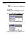
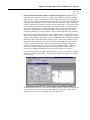
Important Product Information
GFK-1287F
February 2006
READ THIS INFORMATION FIRST
Product: Genius Modular Redundancy Phase IV Software v2.00
IC641SWP745B – Compact Disk
GMR System Software Release 4.04
GMR Configuration Utility Release 8.06
General Description
This is an upgraded version of Genius Modular Redundancy (GMR) software that provides
Windows 2000 support for the Configuration Utility. It also addresses several issues with the
Configuration Utility and System Software.
This version replaces version 8.05a of the Configuration Utility, and 4.02c System software
provided in IC641SWP745A. Software upgrades may be purchased from a distributor.
This version of Genius Modular Redundancy (GMR) software has the features and functionality
described in the GMR User’s Manual, GFK-1277D. A copy of the manual is provided on the CD
with the Configuration Utility.
Compatibility
Logicmaster and CPU
This release requires Logicmaster 90-70 release 6.02 or later.
This new software is only compatible with the IC697CPM790 CPU, release 6.02 or later.
Firmware release 6.03 or later is required to enable the Ethernet interface for programming
This new software is NOT compatible with the IC697CPU788 or IC697CPU789.
Series 90-70 Genius Bus Controller
Release 5.4 or later Genius Bus Controller (IC697BEM731) firmware is required.
Genius Hand-Held Monitor
Hand-Held Monitor IC660HHM501H version 4.5 or later is required.
Genius Blocks
Version 4.02 GMR software supports the following Genius blocks in GMR groups:
▪
▪
All Genius analog input blocks.
The following discrete Genius block versions are compatible with version 4.02 GMR
software: IC660BBD020U, IC660BBD021U, IC660BBD024V, IC660BBD025U
Other types of Genius blocks can be used as non-redundant blocks in the same system.
Field Control Products
The following Field Control devices are supported:
▪
▪
▪
▪
Field Control Bus Interface Unit, version IC670GBI002E.
8-Channel Current Source Analog Input module, version IC670ALG230A.
RTD module, IC670ALG620.
Thermocouple module, IC670ALG630.
Important Product Information: GMR Phase IV Software
GFK-1287F
February 2006
▪
16–Channel Current Source Analog Input module, IC670ALG240.
VersaMax Products
The following VersaMax devices are supported:
▪
▪
▪
▪
Any Versa Max Power Supply
Network Interface Unit IC200GBI001
Any 4-Channel Analog Input Module
Any 8-Channel Analog Input Module
These Field Control and VersaMax modules may be used as voted input devices; however, they
are not included in the list of TUV approved devices.
Incompatible Devices
GMR is incompatible with the Series 90-70 GDS module. The Series 90-70 GMR CPU 790
release 6.02 is incompatible with CIMPLICITY 70.
Problems Resolved by This Release
This release of GMR addresses the following issues of previous release of GMR (4.02c System
Software and 8.05a Configuration Utility).
System Software v4.04
▪
Error code 11501 is correctly reported if a certain section of GMR code is improperly
accessed.
▪
A diagnostic reset occurs on the rising edge of a DIAGRES. This behavior, which triggers a
diagnostic reset on the rising edge of a DIAGRES in any PLC, is consistent with the other
GMR to USER functions.
▪
Starting PLCs simultaneously does not cause a nuisance “Program Changed” to be logged by
one of the PLCs.
▪
Changing ALG block fault reporting for analog block BBA026 does not cause GMR Fault
Handler message 10899.
▪
Changing the configuration of ALG block fault reporting does not unexpectedly cause an
INVALID CONFIG error message.
▪
If there is no I/O present in a duplex or triplex system, the PLC identity is not assumed to be
PLCA.
▪
A system that has communications between PLCs without I/O groups will not have erroneous
Loss of Device 0 faults.
▪
▪
If a %M discrepancy exists, the third PLC will synchronize correctly.
▪
▪
Non-discrepant analog inputs are voted correctly in Duplex mode.
▪
Loading a Simplex configuration into PLCB or PLCC or loading a duplex configuration into
PLCC will correctly generate a mismatch error message.
PLCB and PLC C can be started when PLCA is autotesting the last output group without
causing PLC C to report error “GMR1-ST2@10h”.
If an I/O reset is initiated while there are standing faults on duplex groups, the inputs are
voted correctly.
Important Product Information: GMR Phase IV Software
GFK-1287F
February 2006
▪
During an I/O shutdown, performing an I/O reset does not cause outputs to change state from
their set defaults.
▪
During an I/O reset, premature or spurious inputs will not be incorrectly interpreted as
discrepant inputs.
▪
During an autotest sweep, the output group shutdown timers are triggered consistently.
Configuration Software v8.06
▪
Inserting redundant output groups and changing busses in the configuration does not cause an
overlap in the groups, resulting in an invalid configuration.
▪
▪
The “About Form” reads the owner/organization for Windows NT systems correctly.
▪
▪
▪
The printer settings will be remembered during a current configuration session.
▪
▪
▪
The Rack/Memory/Error dialogs inactivate the GMR I/O Groups section of the toolbar.
VersaMax and Field Control non-voted inputs are not labeled as “voted” on printouts of the
system configuration.
The configuration utility limits the insertion of GBC groups to 31 GBCs.
The configuration utility will not try to reuse Serial Bus Addresses that have already been
used.
The %M Sync data cannot be configured to overlap the reserved %M system status data area.
The maximum watchdog timer setting of 2250ms is correctly reported if a higher setting is
attempted.
Restrictions and Open Problems
All standing faults should be corrected prior to issuing an I/O reset: If an input point has a
standing fault when an I/O reset is initiated, the GMR software clears that fault and includes the
input value from that module in the voting until the Genius device re-reports the fault. This can
cause the voted input to be set to an unrealistic value during the time between the I/O reset and the
time the fault is received. Be sure that all faults are corrected prior to issuing an I/O reset, or
design the application logic to hold the outputs in their current state long enough to allow all
standing faults to be re-reported after an I/O reset.
Configuration of VersaMax modules in GMR systems: There are certain failures of VersaMax
modules that the GMR software does not recognize. If such a failure does occur, instead of
discarding the associated inputs and adapting the voting, the GMR software includes the values
from the faulted Genius NIU in the voting. The result can be that the voted input value becomes
set to the GNIU’s default input value. Therefore, the GNIU’s default input values must be
configured for their safe states.
When VersaMax modules are included in a GMR system, configure the system according to the
following rules:
1.
Using the NIU Configuration Tool within Machine Edition, configure each Genius NIU as
follows:
a. On the “Module Parameters” tab of every input module, the "Default / Hold Last State"
parameter must be set to "Default", and the “Report Faults” parameter must be set to
“Enabled.”
b. On the “Input Parameters” tab of every input module, the default input value for every
input channel must be set to its safe state. The value chosen here should match the default
value chosen for this channel in the GMR configuration (see item #2b).
Important Product Information: GMR Phase IV Software
GFK-1287F
February 2006
c. On the “Network” tab of the GBI001, the "Report Faults" parameter must be set to
"Enabled", and if the NIU is part of a duplex or triplex input group, the "CPU Redundancy"
parameter must be set to "Hot Standby".
2.
Using the GMR Configuration Utility, configure each voted VersaMax input channel as
follows:
a. The Engineering Units Max and Min values must represent the full range of input values
that the module can report to the PLC.
b. The Default State must be set to the safe state.
Use and configuration of Field Control Modules in GMR systems: There are certain failures of
Field Control modules that the GMR software does not recognize. If such a failure does occur,
instead of discarding the associated inputs and adapting the voting, the GMR software will include
the values from the faulted Genius Bus Interface Unit (BIU) in the voting. The net result can be
that the voted input value becomes set to the BIU’s default value, which can only be configured
for 0 or Hold Last State. Therefore, the use of Field Control modules in a GMR system must
be limited to cases where 0 is the safe state for the associated input channels.
When Field Control modules are included in a GMR system, configure the system according to
the following rules:
1.
Using a Genius Hand-held monitor, configure each Field Control Genius BIU as follows:
a. For each module attached to the BIU, fault reporting should be enabled for every channel
that is used, and the "Hld Lst State" parameter should be set to “NO”.
b. The BIU’s “Report Faults” parameter must be set to “YES”.
c. If the BIU is part of a duplex or triplex input group, its “CPU Redundancy” parameter
must be set to “Hot Stdby Mode”.
2.
Using the GMR Configuration Utility, configure each voted Field Control input channel as
follows:
a. The Engineering Units Max and Min values must represent the full range of input values
that the module can report to the PLC.
b. The Default State must be set to the safe state, which should correspond to the value 0.
Special Operating Notes
1.
Misconfiguring the Number of PLCs in the Series 90™-70 GMR System may result in
Unreported Output Discrepancy Faults: The GMR Configuration Utility is used to select
the operational and hardware parameters for a GMR system. Should the user fail to configure
the GMR system with the actual number of PLCs, the GMR software could fail to report some
Output Discrepancy faults.
For example, a Triplex system configured with only two PLCs could result in a failure to
report some discrepant outputs from the third PLC. Likewise, a Duplex system configured
with only one PLC could result in a failure to report some discrepant outputs from the second
PLC. This misconfiguration will not be indicated with a system fault message, and the GMR
PLCs will appear to operate normally.
To assure that there is no such misconfiguration, GE Fanuc advises the use of appropriate
verification procedures, as well as careful configuration practices as identified in the Genius®
Modular Redundancy User’s Manual – GFK-1277.
Important Product Information: GMR Phase IV Software
GFK-1287F
February 2006
Specific verification procedures include:
▪
Ensuring that the current GMR Configuration printout indicates the actual number of
active PLCs.
▪
Using the Logicmaster™ 90 Programming package to toggle the %M12262 –
“REPORT” control reference so that the system will report the current GMR checksum in
the PLC Fault table.
▪
Verifying this checksum with the one listed in the GMR Configuration printout.
Any inconsistencies indicate improper GMR Configuration settings that should be corrected
at the earliest opportunity.
2.
Normal State Must be Configured Appropriately for Critical Outputs in Fire and Gas
Application: Critical outputs in a Fire and Gas application must be configured such that the
‘normal’ state is the opposite of the safe or demand state as appropriate, so that the GMR
diagnostics will perform correctly. For example, normally energized (‘on’) outputs will be
forced to the safe, or de-energized state, in the event of failure, whereas normally deenergized (‘off’) outputs will be forced to the energized state (as in a Fire and Gas
application). To configure outputs in this manner, bring up the GMR Configuration Utility
and select the output group as shown.
Select (mouse click) the Normal State tab for the associated output group, to display the following
screen.
The normal state can be configured on a point by point basis or, with the Select All and Clear All
buttons, can be configured uniformly for all points in that output group.
Important Product Information: GMR Phase IV Software
GFK-1287F
February 2006
3.
Output Autotest Faults When Outputs are Rapidly Changing State: In addition to the
output discrepancy faults that can occur as a result of non-steady-state outputs in redundant
output groups, it is also possible that Output Autotest faults could occur. This may happen
under very narrow timing conditions when the output block’s state has been overridden to the
de-energized state (during the Autotest sequence) and the output value changes. This would
cause the Autotest to fail, resulting in a Output Autotest fault message. A second side effect is
that the output would remain overridden in the de-energized safe state, consistent with TUV
requirements. Note that this TUV requirement applies only to outputs which are normally
energized, as determined by the setting in the GMR Configuration Utility. Those outputs
configured as normally de-energized will not see this particular fault under these conditions.
Because of the asynchronous operation of CPUs in a GMR system, it is possible that output
blocks, while voting the output from three separate CPUs, could “see” a discrepancy when an
output is simply changing states. Earlier versions of GMR dealt with this situation by filtering
discrepancies that occurred during state changes. However, under some circumstances, this
default filter may be inadequate. A field has been added to the GMR Configuration Utility
(revision 7.00 and later) that allows the user to adjust the filter by adding a configurable
number of seconds (between 0 and 65535). In effect, an output discrepancy would have to
exist for the configured number of seconds before being reported as a fault. (For more
information on GMR Output Discrepancy reporting, see the GMR User’s Manual.)
To access the parameter in the GMR Configuration Utility, select ‘View’ from the menu bar,
followed by ‘System Configuration…’ Then select the Options tab to reveal a screen similar
to the one below:
In the Discrepancy Filter area, a value can be entered for Output. A value of ‘0’ will cause the
system to act just as earlier versions of the GMR Software now operate, with the filtering
algorithm described in the User’s Manual. This is the default value.
Important Product Information: GMR Phase IV Software
GFK-1287F
February 2006
4.
Fault Table Contents When a GMR CPU is in Stop Mode: If a GMR CPU has been in Run
mode and on-line, then subsequently is put in Stop mode, some faults may be reported
incorrectly or may not be reported at all. When the CPU is returned to Run mode the fault
table resumes normal operation. Each time a CPU is put into Run mode and on-line, an I/O
fault table reset should be performed by using the GMR “IORES” control bit (%M12258) as
described in the GMR User’s Manual GFK-1277C. This operation will ensure that the I/O
fault table is updated with the current and correct fault information.
5.
An I/O Shutdown Canceled Message is logged in the PLC Fault Table following a
Supervised Output Shutdown: If a fault condition exists for an output group that results in a
supervised output shutdown, the shutdown occurs as it should, but then an erroneous
Shutdown canceled message is erroneously entered in the fault table
6.
Slow response to IORES and FRCLOG after power cycle is to be expected. Following a
power cycle of multiple CPUs, the actions performed by GMR control bits “IORES”
(%M12258) and “FRCLOG” (%M12263) can take several minutes to complete. The GMR
status bit “IORESIP” (%M12238) can be monitored to transition to the off state to verify that
the “IORES” request completed. Subsequent use of these control bits result in normal
response times
7.
Field Control BIUs and Versa Max NIUs must be configured in Hot Standby mode for
proper fault contact behavior. Otherwise, fault contacts may not be consistent in all CPUs.
Hot Standby mode should be used for all input blocks and modules when GMR mode is not
an available selection. Also, the appropriate CPU firmware (6.02) must be used with this
release in order for fault contacts to be cleared properly following an IORESET. (Note: The
Versa Max NIU Configuration Utility must be used in order to place Versa Max NIU in Hot
Standby mode. For more information, contact GE Fanuc Technical Support at 1 800 GE
FANUC )
8.
CPU Memory areas should be cleared as a standard procedure step, when storing
application code and re-starting the system. Otherwise, the redundant PLCs may not
synchronize correctly.