1
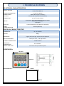
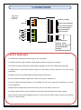
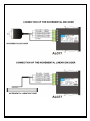
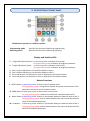
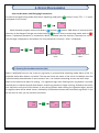
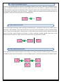
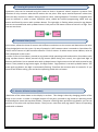
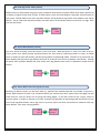
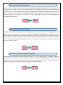
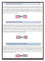
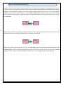
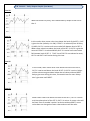
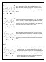
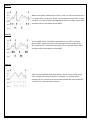
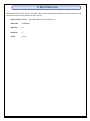
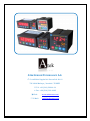
ALC 77 MEASUREMENT INSTRUMENTS 72X72 MM DIMENSION 600 KHZ SPEED READING 2 ROW, 7 DIGITS DISPLAY COUNTING A AND B SIGNAL FUNCTIONAL EXTERNAL Z (RESET) INPUT FUNCTIONAL EXTERNAL HOLD INPUT QUADRATURE UP AND DOWN COUNTING 2 PIECES DOUBLE RELAY OUTPUT MAKE SELECTION ACCORDING TO SET-1 AND SET-2 PRESCALE CAN BE ADJUSTABLE (0,000001 UP TO 9999999 ) DECIMAL BETWEEN 1ST AND 6TH STEP POINT 5 VDC OR 12 VDC SENSOR SUPPLY OUTPUT 11 DIFFERENT OUTPUT CONTROL MODE ENTERING THE OFFSET VALUE PASSWORD SECURITY USER MANUAL INDEX 1. 2. 3. 4. TECHNICAL FEATURES……….………….…………………………………………………………………………………………… 1 CONNECTIONS…………….………………..…………………………………………………………………………………………… 2 DESCRIPTION OF FRONT PANEL ………………………………………………………………………………………………… 3 DEVICE PROGRAMMING …………………………………………………………………………………………………………... 4 4.1. ENTERING SET VALUE TO DEVICE (set)…………………………………………………………………………. 5 4.2. RELAY OUTPUT MODE (output)……………………………………………………………………………………. 6 4.3. RELAY OUTPUT TIME (tout)…………………………………………………………………………..……………… 6 4.4. RELAY OUTPUT POSITIONS(out)…………………………………………………………………….……………… 6 4.5. ENTERING OF HYSTERESIS (hystere)….……………………………………………………………..…………… 7 4.6. ENTERING OF CONSTANT (const)……..…………………………………………………………………………… 7 4.7. SELECTION OF POINT POSITION (point).………………..……………………………………………………… 7 4.8. ENTERING OF OFFSET VALUE (offset)..……………………………………………………………………….… 8 4.9. RESET WITH BUTTON (rst btn)………………………………………………………………………………………. 8 4.10. RESET WITH EXTERNAL Z SIGNAL (rst inpt)..………………………………………………………….……… 8 4.11. ACTIVATING THE HOLD INPUT (hold)..………………………………………………………………………….. 9 4.12. SELECTION OF HOLD TYPE (holdtyp)……………………………………………………………………………… 9 4.13. SELECTION OF SENSOR(NPN/PNP) TYPE (senstyp)………………………………………………………… 9 4.14. SELECTION OF EDGE COUNTING(countyp)….………………………………………………………………… 10 4.15. RETURN TO FACTORY DEFAULTS (factory)……………………………………………………………………. 10 4.16. KEEPING IN MEMORY WHEN THE POWER FAILS DATA.………………………………………………… 10 4.17. PASSWORD PROTECTION (code_in)…………………………………………………………………………….. 11 4.18. ANNEX A – GRAPHICS OF RELAY OUTPUT TYPES (out menu)……………………………………….. 12 5. DATA PROTOCOL…………………………………………………………………………………………………….………………. 15 6. CERTIFICATE OF WARRANTY …………………………………………………………………………………………………… 16 1. TECHNICAL FEATURES ELECTRICAL CHARACTERISTICS 24 VAC/DC 50/60 Hz 85-265 VAC 50/60 Hz SUPPLY VOLTAGE POWER CONSUMPTION 5.5 VA / 4.4 W Max SENSOR SUPPLY VOLTAGE 5 VDC 100 mA (for TTL Sensor) 12 VDC 100 mA (for Push-Pull Sensor) CONNECTION 2,5 mm² screw-clemens A/B Encoder Pulse Inputs (600 KHz speed reading) Z (external reset) Input Hold Input INPUTS OUTPUTS 2 pieces 250 VAC 3A (for Resistive Load) Relay SERIAL COMMUNICATION RS-232 (Optional) PHYSICAL CHARACTERISTICS DIMENSIONS 72 x 72 x 96 mm WEIGHT 300 gr. MOUNTING Upper and lower legs are fixed to the clipboard. RELATIVE HUMIDITY %80 up to 31 °C , %50 up to 40 °C STORAGE TEMPERATURE -10 UP TO 60 °C OPERATING TEMPERATURE 0 UP TO 50 °C PROTECTION CLASS IP 60 Front Panel, IP 20 Back panel DIMENSIONs 73,5 mm 73,5 mm Pano Dimension : 69 mm 69 mm -1- 2. CONNECTIONS 13 3 14 A Input of Counting Signal 4 15 5 16 6 17 7 18 B Input of Counting Signal girişi Z Input of Reset Signal Input of Hold Signal girişi Ground of Sensor 8 19 9 20 10 21 11 22 girişi ucu TX RX GND These outputs are optional. These terminals are open, if is not specified when ordering R S-232 OUT 1 OUT 2 12 2 - CO M NO NC CO NO M NC +5 Vdc or +12 Vdc GND 1 + - L N Ground + - Supply Voltage 24 VAC / DC or 85 / 265 VAC SAFETY WARNINGS 1. Follow the instructions and warnings in the user guide. 2. Please check the type of power supply before connects energy to the device. 3. Please the device mounted on panel against dangers of fall, snap, shake during working. 4. Make Sensor connections without energy on the device; do not connect in any way during operation. 5. Make sure that is shielded cables between device and sensor. 6. Do not leave the device exposed to a heat source (solar, heater etc.) 7. ALC77 industrial control device is not suitable for use in the external environment, Use only room conditions. 8. Wipe with a damp cloth to clean the device, do not use water, thinner etc. 9. Comply with the limit values specified in the technical specifications for relay outputs. 10. The device cannot be changed by the user in the event of a fault, Please contact our technical service in case of failure. -2- -3- 3. DESCRIPTION OF FRONT PANEL ALC44 device operates in 2 different modes: Programming mode Operating modu : Specifies the function used during programming. : Specifies the function used during operating. Display and Position LEDs 1. 7 Digit LED Display (9,2mm) at Operating mode: Indication of counting At programming mode: Indication of program parameter 2. 7 Digit LED Display (7mm) at Operating mode: Indication of Set value. At programming mode: Indication of program parameter 3. Out-1 output LED position: On while the power at Out-1. 4. Out-2 output LED position: On while the power at Out-2. 5. Set-1 Led position: On while Set-1 value is displayed in the bottom display 6. Set-2 Led position: On while Set-2 value is displayed in the bottom display. Button Functions 7. RESET Button at Operating mode: Used to reset of counted value. At programming mode: Using to exit without saving the entered value of the parameter and return to the operation mode. 8. PROG Button at Operating mode: Used to return to the menu. At programming mode: Used to save and enter menu parameter value. 9. Down Button at Operating mode: Used to in the bottom display to show the value of Set-1. At programming mode: Used to switch between the menus and decrease the value of the selected parameter. 10. Up Button at Operating mode: Used to in the bottom display to show the value of Set-2. At programming mode: Used to switch between the menus and decrease the value of the selected parameter. -4- 4. DEVICE PROGRAMMING Enter to the menu and Changing Parameters: For switch to programming mode while device operating mode push ( PRG ) button. Firstly “”s menu will appear on the screen. PRG Switch between program menus with Down ( ) and up ( ) buttons. PRG button is entered into for the menu to be changed. Changes are saved with prg ( PRG) button. Return to operating mode with rst ( RST ) button. If password protection is activated at device, password must be entered. If password is correct, true message is displayed on the bottom line. Also password is incorrect, “false” is displayed. PRG If Password is correct : “true”. If Password is incorrect: “false” 4.1. Entering The Set Point to Device (Set) Menu is displayed firstly on the screen as prg button is pressed while operating mode. Menu of Set 2 is displayed while down button is pressed. The top row shows the name of the menu and bottom row also (yellow marked) selected value in menu content. Set 1, set 2 allows controlling to out1 and out2 relays. Move to the desired set point for setting. The rightmost digit starts flashing when prg button is pressed. Desired point is selected up and down button. Used to prg button for Digits scrolling. Shifted to the left for one step when each press of the button, If pres the prg button when coming the rightmost digits, positive or negative value will be asked. Value is selected by up and down button then saved with prg button. If you do not want to save, you can exit with esc button. . . PRG . -5- . 4.2. . Relay Output Modes (Output) Output menu enables different relay outs according to different set values. There are 11 different output type. For detailed information refer to Annex-A part at the end of the manual. In order to select output mode, pressed to prg button at operation mode. Found to output menu with up-down button and pressed to prg button then bottom row choice flashes. Assigned value with up-down button and saved value by prg button. Then return with rst button to operating mode. . . PRG 4.3. Relay Output Time (tout) Tout menus allow role output times according to entered times. If entered to time as zero, writes hold on the screen. Thus situated, relays will be active during the set value is exceeded. In order to entered output time, if you press to prg button, found tout1 or tout2 menus with up-down button. When pressed prg button, the right- digit of bottom row flashes. Its value is set with up-down button. Each press of the button moves to the left in a digit. Then you can save them. Therefore point is fixed. . . PRG . 4.4. Relay Output Positions (out) Out1 and out2 menus allow positions of the relays. The relay is inactive at Nclose option, active while reached set point. And also yhe delay is active at Nopen option; it will be inactive while reached set point. . . PRG PRG -6- 4.5. Entering Of Hysteresis (hystere) Hysteresis value can be entered using this menu to device. Hysteresis value’s purpose is prevent from vibration of relay contacts when device reaches the set point. After up to entered hysteresis value time, pulls the relay contacts or release. During hysteresis value, nothing happens. Therefore a negligible value must be selected. In order to enter hysteresis value, should be entered programming mode with prg button and found hys menu with up-down button. The right-digit is flashing when pressed to prg button; you can set wanted value with up-down button. Each press of the button moves to the left in a digit. Then you can save them. . . PRG . 4.6. Constant Value (const) Const menu, allows the show of sensors with different resolutions on the screen and determines the value of each edge/pulse on the screen. By way of example, 0,025 constant value is entered to Const Menu for the 25 micron-sensor or 0,005 constant value for 5 micron-sensor. So when sensor moves 100mm, value of 100 is displayed on the screen. In order to set to Conts Menu, pressed to prg button while operating mode and ound to Const Menu with using up-down button. When pressed to prg button (While being cons menu), the right-hand digit of bottom row flashes. Set to wanted value with up-down button. Digit moves to the left while pressed to prg button. Then pressed to prg button again, this digit flashes. Digit position is set with up-down button. You press again prg button, the digit is continuously flashing. Therefore the constant value is entered in. If you want to exit without saving, you can back to operating mode with rst button. . . PRG . 4.7. Selection Of Point Position (Point) Resolution of the value shown on the display is set here. This change is done by changing position of the point on the screen. In order to changed position of the point, pressed to prg button at operating mode and found point menu with up-down button. The point is flashing when pressed to prg button; you can set position of the point with up-down button. Then you can save them with prg button. Return to operating mode with rst button. . . PRG . . -7- 4.8. Entering Offset Value (offset) Offset value can be entered using this menu to device. Returned to entered offset value when pressed to rst button or signal comes from Z input. If offset value is zero and reset button is pressed, zero will write on the screen. Found offset menu with up-down button and pressed to prg button then bottom row choice flashes. Set to value with up-down button and each press of the button moves to the left in a digit. Then you can save them. . . . PRG 4.9. Reset With Button (rst btn) This menu allows becoming active RST button on the front panel. While RST button is active, the value of the onscreen will be reset when pressed up-down button for two times at operating mode or return to offset value. In order to open RST button, pressed to prg button at operating mode. Found Tot rst menu with updown button and pressed to prg button then one of reset/no reset choice at bottom row flashes. Change to option with up-down button and save choice with prg button then return to operation mode with rst button. . . PRG 4.10. Reset With External Z Signal (rst inpt) Resetting at device screen can be done with by applied from outside external an encoder Z signal or a switch when external Z input is be activated. While you make active the Z input, select the edge you will make reset on. You can select one of rising and falling edges. If you don’t want to use Z input, select to noreset option. In order to activate to Z input, pressed to prg button at operating mode and found rst inpt menu with up-down button. When prg button is pressed, options will flash and made the selection with updown button. Then save it by prg button. . . PRG -8- 4.11. Activating The Hold Input (Hold) While hold input is active, value on the screen is fixed when the signal comes of hold input. If signal of hold input isn't cut, counting can not to be continued. While you select the hold input, also select the edge you will make reset on. You can select one of rising and falling edges. If you want to hold off Input, select to off option. In order to select to hold input pressed to prg button at operating mode and found hold menu with up-down button. When prg button is pressed, options will flash and made the selection with up-down button. Then save it by prg button. . . PRG 4.12. Selection of Hold Type (Holdtyp) Holdtyp menu is selected counting in the background, when value of on the screen is fixed (while hold input is active). The value of on the screen is fixed, if hold signal is applied while count option is active. When signal is interrupted, continue to counted value. In order to select hold type, pressed to prg button at operating mode and found h.type menu with up-down button. When prg button is pressed, options will flash and made the selection with up-down button. Then saved it by prg button and Returned with rst button to operatin mode. . . PRG 4.13. Selection Sensor Type (Npn/Pnp) (Senstyp) The used sensor type can be selected from this menu. The sensor output signal is selectable as NPN or PNP. In order to selected sensor type, pressed to prg button at operating mode and fount S.typ menu with up-down button. When prg button is pressed, options will flash and made the selection with up-down button. Then save it by prg button and returne with rst button to operating mode. . . PRG -9- 4.14. Selection Of Edge Counting (Countyp) This menu allows selecting the number counting of edge of Encoder A and B signals. Counting option is 1, 2 and 4. If incremental encoder is connected, “1” is selected to see the pulse in terms of the value of the onscreen. 4 (quadrature mod) is selected to more precise measurement. In order to changed selection of edge counting pressed to prg button at operating mode and found countyp menu with up-down button. Option of bottom row will flash and made the selection with up-down button. Then save it by prg button and return with rst button to operating mode. . . PRG 4.15. Return to Factory Defaults (Factory) Factory menu enables to return the first fabrication settings of device. At this situated, all device setting will change, and for this reason important settings should be saved previously. Device will require the password for returning to factory defaults and this password is 454. In order to return to factory defaults, pressed to prg button at operating mode and found to factory menu with up-down button. When prg button is pressed at menu screen, the right-digit of bottom row is flashing and changed value with updown button. When pressed to prg button, moves to the left in a digit and you can set it as 454 and pressed to prg button. So device will return to factory defaults. . . PRG 4.16. Keeping In Memory When The Power Fails (Data) Data menu enables to keep in memory the last value on the screen even if the energy is cut off and must be selected record for this option. So the final value will be memorized when energy is cut off and resumes again when energy comes back. Recording process will not be stored to device memory while Clear is selected, and then value will start from zero. In order to change data menu, pressed to prg button at operating mode and found Data Menu with up-down button. Then saved it by prg button and returned with rst button to operating mode. . . PRG - 10 - 4.17. Password Protection (Code_in) Password security enables that unauthorized persons is prevented to change the parameters of the menu. If Code-in menu is on position, you can enter to device’s menu and password is required for any setting changes. If the password is wrong, you cannot change anything. While code in menu is off, the password protection is not active. If Code_in menu is on, recode is added to menu titles. In order to turn on Code-in menu, pressed to prg button at operating mode and found Secu Menu with up-down button. Then save it by prg button. . . PRG When Code_in menu is on position, recode is added to menu titles. Recode menu enables identification of password to device. Default password is 000, if you have not changed. PRG When prg button is pressed at menu screen, the right-digit of bottom row flashes and change value with up-down button. When Pressed to prg button, moves to the left in a digit. So you can set the value with up-down button and save them when pressed to prg button at third digit. So password is defined. - 11 - 4.18. Annex A – Relay Output Graphic (Out Menu) Out 00 While out mode is 0 (zero), don’t observed any output at Out-1 and Out-2. Out 01 In this mode; when count value rises above the level of the SET-1, OUT1 gives the out (so Relay-1 is ON). If TOUT-1 is selected (Time of Relay1) HOLD, OUT-1 is active until count value falls bottom level of SET-1. When count value rises above the level of the SET-2, OUT-2 is give the out and If TOUT-2 is selected HOLD, OUT-2 is active until count value falls bottom level of SET-2. TOUT-1 and TOUT-2 are selected as term, OUT-1 and OUT-2 will active during this time. Out 02 In this mode, when count value rises above the level of the SeT-1, OUT-1 is active and above the level of SET-2, OUT-2 is active. Relays will be active even goes down below the set values without RESET. Relays give outs during this time, if entered times for outs. Relays don’t give outs until RESET. Out 03 When count value rises above the level of the SeT-1, OUT-1 is active and rises above level of the SET-2, OUT-2 is active. So count value will be fixed. Even if encoder’s pulse is at device without RESET, count value does not change but count value and outs will be reset. - 12 - Out 04 OUT-1 depends to OUT-2 and TOUT-2 should be selected as term. When count value rises above the level of the SET-1, OUT-1 is active and rises above level of the SET-2, OUT-2 is active. So count value will be fixed. Outputs and count value will be reset at the end of TOUT-2 period. Out 05 Output-4 continues counting after level of set-2 value. OUT-1 depends to OUT-2 and TOUT-2 should be selected as term. When count value rises above the level of the SET-1, OUT-1 is active and rises above level of the SET-2, OUT-2 is active. So count value will be fixed. Outputs and count value will be reset at the end of TOUT-2 period. Out 06 When count value rises above the level of the SET-1, OUT-1 is active and rises above level of the SET-2, OUT-2 is active. TOUT terms while selected HOLD, there is no outputs even to count value falls bottom level of SET values. Outputs will be reset when count value reaches zero (OFFSET), besides count value and outs will be reset when comes RESET. Out 07 When count value rises above the level of the SET-1, OUT-1 is active and then Relay is inactivate end of the TOUT-1 period. If TOUT-1 term is selected as HOLD, OUT-1 will be inactive when count value goes down below the level of the SET-1 and rises above the level of the SET2, OUT-2 is active. It will be inactive end of TOUT-2 period. If TOUT-2 term is selected as HOLD, OUT-2 is not active even to TOUT-2 time HOLD even if the count value is below the level of SET-2 value. OUT-2 will be zero when count value reaches zero (OFFSET). Besides count value and outs will be reset when comes RESET. - 13 - Out 08 While count value is below level of Set-1, Out-1 is active and then Out-1 is inactive when on top of it. Out-2 is active when on top of SET-2 value and OUT-2 is inactive after reaching below the SET-2 value. Count value and outs will be reset when comes RESET. Out 09 At this mode, TOUT-2 should be selected as term. OUT-1 is active during TOUT-1 period at count value exceeds the each value of the SET-1 and OUT-1 is inactive at the end of TOUT-2 period. Count value and outs will be reset when comes RESET. Out 10 TOUT times should be selected as HOLD. OUT-1 is active until count value reaches the value of the SET-2 and OUT-2 is inactive when reaches. OUT-2 is active until count value reaches the value of the SET1 and OUT-1 is inactive when reaches. - 14 - 5. DATA PROTOCOL Parameters of ALC77 RS-232 are as below. There are no settings on the device. Communication is oneway towards the terminal device to the receiver. Data’s format : RS232 EOL (16bit Data+ EOL (End of Line) ) Baud rate : 57600 bps Data bits :8 Stop bits :1 Parity : none - 15 - 5. CERTIFICATE OF WARRANTY Product : ALC77 85/265 VAC TTL RS-232 24 VAC/DC Push Pull Serial No : …………………………………… This product is guaranteed for two years against manufacturing defects. Conditions out of the warranty: - Mechanical damage - Shipping damage - Users error Other situations is covered by the manufacturer's warranty. Signature and Stamp - 16 - ATEK SENSOR TECHNOLOGY A.S. Cevizli Mah. Bagdat Cad. Guven Sok. No:11 TR-34846 Maltepe / Istanbul - TURKEY Tel: +90 (216) 399 44 04 Fax : +90 (216) 399 44 02 Web: www.ateksensor.com E-Mail: [email protected]