1
15
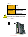
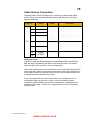
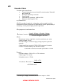
Cable Screen Connection
Terminals X24/07 and X24/08 are for connection to the encoder cable
screen. Either one or both terminals can be used; they are connected
together internally.
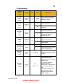
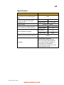
Terminal
X24
Name
Range
01
Channel A
02
Channel /A
±3V to
±24V
(differential)
03
Channel B
Or
04
Channel /B
0V to 24V
(singleended)
05
SUPPLY
POSITIVE
06
SUPPLY
NEGATIVE
07
08
Selectable
5V, 12V,
15V and
24V
Description
Encoder inputs, compatible
with a wide range of
encoders.
The user can program the
inputs to be differential or
single-ended.
Software-selectable power
supply output to encoder.
CABLE
SCREEN
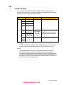
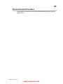
Important notes:
In order to meet the Electro-Magnetic Compatibility (EMC) specification,
both the motor screen and encoder screen should both be connected
directly at the motor and drive, and not interrupted.
If the motor cable screen is not continuous or not connected directly at the
motor and drive, earth currents that should return to the drive through the
motor cable screen may instead return via the encoder cable screen, and
unreliable encoder operation may result.
If it is not possible for the motor cable screen to be continuous or not
connected directly at the motor or drive, encoder reliability may be
improved by disconnecting the encoder cable screen, preferably at the
encoder. In this case, it is the user’s responsibility to ensure the system
works reliably.
AC30V Encoder Option
www.comoso.com