1
KRAMER ELECTRONICS, Ltd.
USER MANUAL
SCAN CONVERTERS
Models:
VP-704SC, VP-705SC, VP-706SC
IMPORTANT: Before proceeding, please read paragraph entitled
"Unpacking and Contents"
KRAMER ELECTRONICS, LTD.
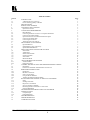
Table Of Contents
Section
1
1.1
1.2
2
3
4
4.1
5
5.1
5.2
5.3
5.4
5.5
5.6
5.7
6
6.1
6.2
6.3
7
7.1
7.2
7.3
7.4
7.5
7.6
8
8.1
8.2
9
9.1
9.2
10
10.1
10.2
10.3
10.4
10.5
11
11.1
11.2
11.3
11.4
11.5
11.6
12
13
13.1
13.2
14
15
16
Page
INTRODUCTION
A Word about Scan Converters
Factors Affecting Quality of Results
SPECIFICATIONS
HOW DO I GET STARTED?
UNPACKING AND CONTENTS
Optional Accessories
CONNECTING THE HARDWARE
Rack Mounting
Connecting the Scan Converter to a Computer and Monitor
Connecting the Video Outputs
Optional Connection of an External Reference Signal
Connecting the Serial Cable
Connecting the AC Power
Turning the Scan Converter On
ABOUT THE SCAN CONVERTER
Quick-Set Buttons
Special Button Usage on Power-up
Special Multi-Hold Buttons
MENU STRUCTURE AND FEATURE CONTROL
Status Mode
Adjust Menu
Studio Genlock Mode
Screen Size Mode
Zoom Mode
Manual Set Mode
ADVANCED MENUS & FEATURES
Advanced Menu
Engineering Menu
CONTROL AND SETUP USING THE INFRARED REMOTE CONTROL
Introduction
Functions of the RM-SC Infrared Remote Control Unit
REMOTE MOUSE EMULATOR
Introduction
Hardware Connection
Scan Converter Setup
Using the Mouse Emulator
Toggling Zoom/Pan and Mouse Modes
RS-232 COMPUTER CONTROL OF THE SCAN CONVERTER
Setup
Sending Commands
Responses to Commands
Notes on Sending Commands
Restricting RS-232 Commands to Certain Units
Changing Baud Rates
GETTING THE MOST FROM YOUR SCAN CONVERTER
TECHNICAL DATA
Computer Input
Fuse Replacement
TROUBLESHOOTING
LIMITED WARRANTY
COMPLIANCE NOTICE
KRAMER ELECTRONICS, LTD.
2
3
3
3
4
5
5
5
5
5
5
5
6
6
6
6
7
7
7
8
8
8
9
10
10
11
11
12
13
15
16
16
17
19
19
19
19
19
19
19
19
20
20
20
20
20
22
23
23
23
24
26
27
1
INTRODUCTION
Congratulations on your purchase of this Kramer Electronics Scan Converter. Since 1981, Kramer has been
dedicated to the development and manufacture of high quality video/audio equipment. The Kramer line has
become an integral part of many of the best production and presentation facilities around the world. In recent
years, Kramer has redesigned and upgraded most of the line, making the best even better. Kramer’s line of
professional video/audio electronics is one of the most versatile and complete available, and is a true leader in
terms of quality, workmanship, price/performance ratio and innovation. In addition to the Kramer line of high
quality Scan Converters, such as the one you have just purchased, Kramer also offers a full line of high quality
video scalers, matrix switchers, distribution amplifiers, processors, interfaces, controllers and computer-related
products. This manual includes configuration, operation and option information of the following Kramer Scan
Converters for the video professional. These Scan Converters are similar in operation but differ in features.
VP-704SC
1.1
VP-705SC
VP-706SC
A Word about Scan Converters
Kramer’s Digital Scan Converters are designed to convert computer signals of varying resolutions and vertical
refresh rates into standard NTSC and PAL video signals. NTSC and PAL television systems are much lower in
resolution than typical computer signals. Computers can often output over three times as many horizontal lines
as standard analog television resolutions. Scan Conversion is the process of fitting a higher number of lines of
information into a lesser number of available spaces. Kramer Scan Converters are designed and manufactured
to the highest possible performance standards and are capable of providing high resolution results, however, it is
important to understand the overall process of scan conversion and its inherent limitations.
1.2
Factors Affecting Quality of Results
There are many factors affecting the quality of results when computer images are converted to standard video.
An entire section of this manual entitled ‘Getting the Most from your Scan Converter’ goes into detail, but here
are a few major points up front.
Beginning Resolution – As a general rule, the less the conversion ratio, the better the results. Standard
NTSC and PAL resolutions are near the computer’s VGA resolution of 640x480, so generally, the nearer
you begin to that resolution the better the results. The common mistake is to assume that the higher the
beginning computer resolution, the better the NTSC or PAL results. The reverse of this is the actual fact.
Sometimes a lower beginning computer resolution in not possible, but when it is possible, use it.
Output Display Device – The S-Video or RGB output will provide a better final image, because unlike
the Composite output, the luminance and color signals are kept separate. This results in less color
smearing and a sharper image. When possible, use the S-Video or RGB output, rather than Composite.
Distance between the computer and Scan Converter – This plays a major role in the final result and
the distance should be kept to a minimum. The Scan Converter is supplied with a high quality 6’
computer input cable. Longer distances are possible, but special measures should be taken in order to
avoid cable losses. These include using high quality (coax-type) cables or adding line amplifiers.
Output connection cables – Low quality cables are susceptible to interference. They degrade signal
quality due to poor matching and cause elevated noise levels. Therefore, cables should be of the best
quality.
Interference from neighboring electrical appliances – These can have an adverse effect on signal
quality. For example, an older computer monitor often emits very high electromagnetic fields that can
interfere with the performance of video equipment in its proximity.
Kramer Electronics Ltd.
3
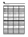
2
SPECIFICATIONS
VP-704SC
VP-705SC
VP-706SC
Computer Input
RGB with HV Sync
RGB with Composite Sync
RGB with Sync on Green
RGB with HV Sync
RGB with Composite Sync
RGB with Sync on Green
RGB with HV Sync
RGB with Composite Sync
RGB with Sync on Green
Maximum Input
Resolution
Maximum Vertical
Refresh Rate
Maximum Horizontal
Scan Rate
Computer Input
Connection
Input Level
1600x1200
1280x1024
1600x1200
150Hz
150Hz
150Hz
100KHz
100KHz
100KHz
HD15 Jack
HD15 Jack
HD15 Jack
RGB @ 0.7V Peak Level
H&V Sync @ TTL
RGB @ 0.7V
H&V Sync @ TTL
RGB @ 0.7V
H&V Sync @ TTL
Video Outputs
VGA Loop-thru
Composite Video @ 1V P-P
S-Video @ 1V P-P
RGBS @ 0.7V P-P, TTL Sync
RGBHV @ 0.7V P-P, TTL Sync
YUV (Y,R-Y,B-Y)
VGA Loop-thru
Composite Video @ 1V P-P
S-Video @ 1V P-P
RGBS @ 0.7V P-P, TTL Sync
RGBHV @ 0.7V P-P, TTL Sync
YUV (Y,R-Y,B-Y)
VGA Loop-thru
Composite Video @ 1V P-P
S-Video @ 1V P-P
RGBS @ 0.7V P-P, TTL Sync
RGBHV @ 0.7V P-P, TTL Sync
YUV (Y,R-Y,B-Y)
Video Standard
NTSC/PAL Switchable
NTSC/PAL Switchable
NTSC/PAL Switchable
Output Connectors
Composite Video on BNC,
S-Video on 4-Pin Mini-DIN
RGBS on BNCs
YUV (shares RGBS BNCs)
Composite Video on BNC
S-Video on 4-Pin Mini-DIN,
RGBS on BNCs
YUV (shares RGBS BNCs)
Composite Video on BNC
S-Video on 4-Pin Mini-DIN,
RGBS on BNCs
YUV (shares RGBS BNCs)
Genlock Signal
Genlock Connection
Image Scaling
N/A
N/A
Proprietary Method
Composite or Blackburst 1V P-P
2 BNC (Loop-through)
Proprietary Method
Composite or Blackburst 1V P-P
2 BNC (Loop-through)
Proprietary Method
AutoTrack™
Proprietary Automatic Image
Sizing and Positioning
Proprietary Automatic Image
Sizing and Positioning
Proprietary Automatic Image
Sizing and Positioning
Zoom & Pan
2X
2X
2X
Flicker Reduction
2, 4 or 6-Line
2, 4 or 6-Line
2, 4 or 6-Line
Control Type
Manual Front Panel Buttons
(with Front Panel LCD Display)
RS-232 Serial
Infrared Remote Control
Manual Front Panel Buttons
(with Front Panel LCD Display)
LCD Display
RS-232 Serial
Infrared Remote Control
Manual Front Panel Buttons
(with Front Panel LCD Display)
LCD Display
RS-232 Serial
Infrared Remote Control
Subcarrier Lock
Locked to Line Frequency
Locked to Line Frequency
Locked to Line Frequency
Weight
2.0 kg (4.4lbs.) Approx.
2.0 kg (4.4lbs.) Approx.
2.0 kg (4.4lbs.) Approx.
Dimensions (HxWxD)
19" x 7" x 1.75” (1RU)
(482mm x 178mm x 44.5mm)
19" x 7" x 1.75” (1RU)
(482mm x 178mm x 44.5mm)
19" x 7" x 1.75” (1RU)
(482mm x 178mm x 44.5mm)
Power Source
100-240VAC, 50/60 Hz
100-240VAC, 50/60 Hz
100-240VAC, 50/60 Hz
Power Consumption
650mA
650mA
650mA
Kramer Electronics Ltd.
4
3
HOW DO I GET STARTED?
The fastest way to get started is to take your time and do everything right the first time. Taking 15 minutes to
read the manual may save you a few hours later. You don’t even have to read the whole manual - if a certain
section doesn’t apply to you, you don’t have to spend your time reading it.
4
UNPACKING AND CONTENTS
The items contained in your Kramer accessory package are listed below. Please save the original box and
packaging materials for possible future transportation and shipment of the unit.
Scan Converter
AC Power Cable
VGA Input Cable
Composite Video Output Cable
S-Video Output Cable
75 OhmTermination BNC Plug (VP-705SC and VP-706SC Only)
Infrared Remote Control Unit
Rackmount Screws (Qty 4) for EIA 19” Racks
User Manual
Kramer Concise CD ROM Product Catalog
4.1
Optional Accessories
The following optional accessories, which are available from Kramer, can enhance implementation of your Scan
Converter. For information regarding these accessories, contact your Kramer dealer.
RGB Output Cable Assembly – 4 or 5 BNC Type
YUV Output Cable Assembly – 3 BNC Type
RS-232 Cable
BNC Computer Input Adapter – HD15 to 5 BNCs
5
CONNECTING THE HARDWARE
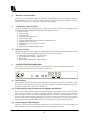
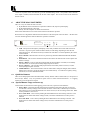
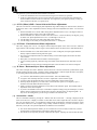
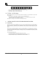
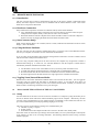
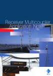
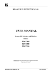
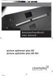
The first step is to connect the Scan Converter and related hardware. Below is a drawing of the rear panel.
(The VP-704SC does not have the GL IN and GL OUT connectors.)
POWER
o
100-240V 50-60HZ
5.1
RS232
VGA IN
VGA OUT
SV OUT
GL
IN
R
R-Y
GL
OUT
CV
G
Y
B
B-Y
HS
CS
VS
OUTPUTS
Rack Mounting
Each of the Scan Converters described in this manual mount in a standard 19” (1RU) EIA rack assembly. These
devices do not require spacing above or below the unit for ventilation. Four standard rackmounting screws are
provided for each of the four corner holes in the rack ears.
5.2
Connecting the Scan Converter to a Computer and Monitor
Disconnect the computer monitor’s input cable from the computer’s VGA output connection. Connect this cable
to the 'VGA OUT' connector on the back of the Scan Converter. Macintosh computers that do not have an
HD15 type output connector may require an additional adapter. Next, use the VGA cable supplied to connect
the VGA output connection from the computer to the ‘VGA IN’ connector on the back of the Scan Converter.
After these connections are made and the computer and monitor are switched on, you will see the computer’s
output displayed on the computer monitor as before, even when there is no power to the Scan Converter.
5.3
Connecting the Video Outputs
The Scan Converter provides several different output types to allow connection to various video displays and
other equipment. The choice of output type depends on what your equipment can accept.
Kramer Electronics Ltd.
5
Composite Video - use the composite video cable provided to connect from the composite video output
on the back of the Scan Converter (the BNC connector marked CV) to the composite video input of your
target video equipment.
S-Video - use the S-Video cable provided to connect from the S-Video output on the back of the Scan
Converter to the S-Video input of your target video equipment. S-Video provides improved performance
over Composite Video.
RGB with Composite Sync - Use a 4xBNC to 4xBNC cable to link from the Red, Green, Blue, and
HS/CS outputs to the video display. The Scan Converter defaults to outputting negative-going CS
(Composite Sync) on the HS/CS connector, but if you encounter problems then it is likely that this has
been changed - see 'Advanced Features' later in this manual. Please note that this output’s horizontal
scan rate is 15.75KHz and is not intended for connection to a computer monitor.
RGB with H&V Sync - Use a 5xBNC to 5xBNC cable to link from the Red, Green, Blue, HS/CS and
VS outputs to the video display. Since the Scan Converter defaults to outputting CS (Composite Sync)
on the HS/CS and VS connectors, so you must see 'Advanced Features' later in this manual in order to
change this to the required separate H&V Syncs. It is recommended that another output be used, until
operation of the unit is understood.
YUV Component (Y,R-Y,B-Y)- Use a 3xBNC to 3xBNC cable to link from the Y, R-Y and B-Y
outputs to the video display. If the Scan Converter is set to output RGB mode (this is the default) it will
be necessary to switch to YUV. See the section on switching between RGB and YUV modes in the
Advanced Features section of this manual. It is recommended that another output be used, until
operation of the unit is understood, because in the YUV Mode, no other video output signals are present.
5.4
Optional Connection of an External Reference Signal (N/A on VP-704SC)
The VP-705SC and VP-706SC have the ability to synchronize their video output with a master Reference
Signal, in the form of a Composite Video or Blackburst source. This is done by connecting the Reference
Signal to the BNC connector marked 'GL IN'. A loop-through output is available at the 'GL OUT' BNC
connector for connection to other devices. Note - If no loop-through is required, you must connect the supplied
75 Ohm BNC termination plug to the 'GL OUT' connector instead; otherwise, the unit may not be able to
maintain a lock on the Reference Signal.
Synchronization is not automatic; you need to enable it within the unit. You should also ensure that the
Composite Video or Blackburst signal used is of the right standard (PAL or NTSC), and that it is a clean, stable,
standard signal. Video signals from consumer VCRs and some non-standard equipment may not be suitable.
5.5
Connecting the Serial Cable
The Scan Converter can be controlled from a computer, and used as a remote Microsoft® serial mouse emulator
by connecting its RS-232 port to a computer's RS-232 port. See the section on 'RS-232 Computer Control' later
in this manual on how to use this control feature (RS-232 Control is the default, and merely requires connecting
a suitable RS-232 cable).
5.6
Connecting the AC Power
The Scan Converter requires an AC input power source of 100-240VAC@50-60Hz. With the Power On/Off
switch on the rear of the Scan Converter in the Off position, plug the AC Cable supplied into the AC Receptacle
on the back of the unit and plug the AC Cable into the power outlet.
5.7
Turning the Scan Converter On
Make sure that all cables are connected and that all other equipment is turned on - your computer monitor
should be functioning normally. The Scan Converter’s AC Power Switch on the rear panel should be switched
on. When using a multi-purpose TV-Monitor, be sure and select the correct line input (AUX or AV). The video
monitor should now be displaying the same picture as is on the computer monitor.
When the Scan Converter is switched on, the green LED indicator on the front panel will illuminate. If there is a
picture on the video monitor, but it is the wrong shape, position or color it may be necessary to alter some of the
status settings before a good picture is displayed. For example, it may be necessary to switch to PAL or NTSC
settings. Further details on selecting the correct settings for your displays follow in the Advanced Features
section. If there is no picture on the video monitor, then go to the Troubleshooting section.
Kramer Electronics Ltd.
6
If there is no picture on the video monitor, go to the Troubleshooting section. One possible cause is that the
YUV output is enabled, which will blank out all other video outputs. This is also covered in the Advanced
Features section.
6
ABOUT THE SCAN CONVERTER
There are 3 ways to control the Scan Converter:
By the Buttons on the Front Panel in conjunction with the LCD (Liquid Crystal Display).
By the Infrared Remote Control unit.
Directly from the computer via the RS-232 Serial Port.
Each control method has its own section of this manual to describe the operation.
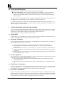
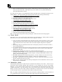
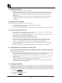
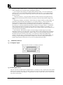
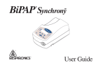
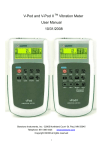
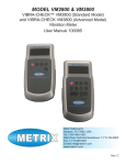
Shown below is a diagram that indicates the main features of the front panel of the VP-706SC. All three Scan
Converter models appear the same and their basic operation is identical.
IR
KRAMER VP-706SC
MENU
Digital Scan Converter
OS/US
FREEZE
+
POWER
VP-706SC
LCD - The top line of the liquid crystal display (LCD) always indicates the current mode of the Scan
Converter. At power-up, this will be the 'Status' mode, but will change, depending on what the user
wants the unit to do. The bottom line always indicates the value that is or will be adjusted by the various
control methods
Power On LED – When the Scan Converter is powered up, the button labeled POWER will illuminate
green.
Menu Button – This is used to initiate Front Panel control of the unit and select the various options and
features to change.
OS/US (-) Button – This is a dual-purpose button that will be described in a moment, but is normally
used to decrease (or de-select) the currently displayed option or feature.
Freeze (+) Button – This is another dual-purpose button, but normally used to increase (or set) the
currently displayed option or feature.
Audible Indicator – The internal sounder is used to confirm that a setting has changed, and to indicate
that the Scan Converter is saving the settings to non-volatile memory. You will hear it regularly during
normal use, but it can be disabled if needed.
6.1
Quick-Set Buttons
These are the dual-purpose buttons described earlier and only function when in Status mode (i.e. the top line of
the LCD says 'Status'). They are provided for quick access to certain often-used functions - i.e. Toggling
Underscan /Overscan and Freeze On/Off.
6.2
Special Button Usage on Power-up
Certain buttons can be held down when applying power to the unit, to perform certain functions:
Factory Reset – Hold down both the OS/US and Freeze Buttons when turning the unit on. This will
reset the unit to Factory Settings (and set the unit into NTSC video mode). It should only be used if the
unit's settings give an invalid output that the user cannot exit from, as all user-settings will be lost. Noteuse this procedure as a last resort.
Set to NTSC Mode – This is done by holding the OS/US Button down when turning on the unit. This
changes the non-volatile PAL/NTSC setting to NTSC, and will be remembered even when power is
removed.
Set to PAL Mode – This is done by holding the Freeze Button down when turning on the unit. This
changes the non-volatile PAL/NTSC setting to PAL, and will be remembered even when power is
removed.
Kramer Electronics Ltd.
7
6.3 Special Multi-Hold Buttons
Certain buttons can be held together when the unit is on to perform other functions.
Store Current Settings - This is done by holding the MENU and FREEZE (+) Buttons in together for
about 2 seconds and can be done at any time. This stores the current settings (e.g. Overscan, YUV
Mode, etc.) in Non-Volatile Memory and cause the Scan Converter to come up in those modes the next
time it is turned on.
This option will emit a high-pitched beep when complete to indicate that data has been successfully stored. If
you manage to store an invalid setting, you may need to do a Factory Reset (see above).
If you hear high pitch beeps at other times, it indicates that other data is being stored into memory – e.g.,
information the Scan Converter has deduced about the graphics resolution coming from your computer, such as
when you change your screen resolution.
7
MENU STRUCTURE AND FEATURE CONTROL
This section goes through the Main Menus available via the LCD and what control they provide over the Scan
Converter. Internally, the Infrared and Serial control links change the features in the same way as the buttons,
so this section is required reading whatever the final method of control is likely to be.
Advanced features are covered in a later section of this manual.
7.1
Status Mode
In Status Mode, you are presented with a summary of some of the current settings. Almost all of these are
repeated (and adjustable) elsewhere in the menu system, but some are not.
7.1.1
Overscan - Quick Set
This is called Quick Set because you don't have to scroll through menus to alter this option. The OS/US (-)
Button toggles between Underscan and Overscan.
Underscan Mode (sometimes know as Compress mode) will leave a border around the image.
Overscan Mode has no border and the displayed image, when set correctly, is larger than the video
monitor screen.
If Underscan and Overscan don't give you the image sizes you expect (for example, Overscan still shows
a border), then make sure you perform the AutoTrack™ function, which is described later in this section
of the manual.
Both the Underscan and Overscan sizes are user-adjustable and the method of doing so will be described
later under the 'Screen Size...' section.
7.1.2
Freeze - Quick Set
This is another Quick Set button, labelled 'FREEZE'. When pressed the first time, the unit will enter a special
mode where the video image and all other features are frozen.
Freeze will remain active until disabled by pressing 'FREEZE' again, and the whole unit will remain
frozen until this happens.
No other features are accessible while in Freeze Mode, except the RESET button on the Remote Control
unit.
7.1.3
Total Lines - Information
This is for information only and will appear when in Status Mode to show how many scan lines are in the
incoming computer picture. It includes blanked lines that are not normally viewable, so a 1024x768 image
might actually have a total of 806 lines in it, with 38 of them used for vertical blanking.
7.1.4
Vert Freq - Information
Again, this is just for information and shows the Vertical Refresh rate of the incoming computer signal.
Multiply this by the 'Total Lines' value to give the Horizontal Scan Rate. While high refresh rates are generally
more acceptable when displayed on computer monitors, Scan Converters prefers a low refresh rate so that their
capture circuitry has more time to capture more pixels, thus giving a clearer picture.
Kramer Electronics Ltd.
8
7.2
Adjust... Menu
You can enter the ‘Adjust…’ Menu directly from the Status Mode by pressing the MENU Button once. This
enters the beginning of a number of Menus that allow complete control over the Scan Converter's features. All
Menus time-out after about 25 seconds of inactivity and return you to the Status Mode. Alternatively, you can
press the + Button when 'Exit' is displayed at the end of each Menu list to return to the previous Menu.
The various options from the ‘Adjust…’ Menu are all selected by pressing the MENU Button repeatedly:
7.2.1
Flicker Reduction
The unit defaults to the 4-Line Flicker Filter Mode, which is best for 800x600 and 1024x768 resolutions.
Pressing the + or – Buttons when this option is displayed will change this to 2-Line or 6-Line.
2-line Mode is not advisable, unless the vertical image softening that is present because of higher flicker
reduction modes needs to be avoided. Line dropping will be common at this setting.
4-line Mode is best for resolutions around 800x600 and 1024x768, but is subject to personal taste and
the exact nature of the graphics or text being displayed. Thin horizontal lines cause the most flicker, and
if this is seen, then the highest flicker reduction setting should be used.
6-line Mode offers the maximum amount of flicker reduction and allows images, even CAD wire-frame
drawings, at resolutions above 1024x768 to be displayed without line dropping. This mode may not be
suitable for low resolutions, because of excessive vertical softening of the image, but this is a mater of
personal preference.
7.2.2
AutoTrack™
AutoTrack™ is Kramer’s unique auto setup routine that automatically sizes, shifts and centers the computer
image onto the video monitor. Once activated, this feature will scan the incoming computer image to determine
its size and position and optimize it for display on the desired video display.
When the Scan Converter first encounters a new screen resolution or refresh rate, it will estimate how to best
display this on the video monitor. Sometimes this estimate needs refining and the AutoTrack™ function allows
the unit to search for the image edges to improve on this.
Before running the AutoTrack™ function, set the computer so that it is displaying a light colored
background or wallpaper with defined edges in full screen mode. If you have a Windows operating
system, make sure it is maximized to use the full screen. Black or very dark colors along the edge of the
image may cause AutoTrack™ to misread the source image’s size.
If you are running MS DOS, it is only recommended to use this function when the full DOS screen is
being used by a fairly bright color or shade of white.
Only use this feature when the full area of the computer screen is being used - this will ensure that the
unit 'sees' the edges correctly, and performs its task without errors.
Pressing the + Button when AutoTrack™ is displayed on the LCD will start this routine and it will take
about 15 seconds. During this time the image on the video monitor will move around, but at the end of
this the image should be stable and correctly sized and centered.
If you encounter problems when running AutoTrack™, you can adjust the level at which it works - see
the LEVEL button described later.
Once complete, the AutoTrack™ routine will remember this particular resolution and refresh rate so that
you should not need to re-do this function next time. The only exceptions are if you change the
computer’s screen resolution, do a Factory Reset or use this unit with a different computer.
If the AutoTrack™ feature does not look like it is finding the edges of the display correctly, then you can
press RESET to stop it going any further.
Note - A high-pitched beep will be heard when the AutoTrack™ function is complete.
7.3
Studio Gen... Mode (Genlock not available on the VP-704SC)
This is a Sub-Menu and selected by pressing the + Button when ‘Studio Gen…’ is displayed on the lower line of
the LCD display. Within this Sub-Menu, you can define the Scan Converter's Studio Genlock features - i.e.
whether Synchronization Mode is On or Off, Subcarrier Phase, etc. All these settings can be stored in nonvolatile memory by using the STORE feature (i.e. hold the Menu and the + Button together or press the STORE
button on the Remote Control).
7.3.1
Genlock - Locking to an External Reference Signal
Kramer Electronics Ltd.
9
This option lets you turn the Studio Genlock feature On and Off.
In the Off condition the Scan Converter functions using its own internal sync generator.
In the On condition the Scan Converter will synchronize itself to the external reference signal fed into
the GL IN BNC connector on the rear of the unit. If no signal (or a poor signal) is present, you may get
erratic results from the unit, or no picture at all.
7.3.2
SC Ph. (Phase) Shift - Coarse Subcarrier Phase Adjustment
The Scan Converter has a full 360 degree phase adjustment range when locking to an external source, but this is
broken down into a Coarse Adjustment (with two settings) and a Fine Adjustment (SC Phase - see next menu
option).
With SC Ph. Shift set to 0, the SC Phase setting allows adjustment from -150 to +150 degrees relative to
the incoming reference signal. This is the normal setting.
With SC Ph. Shift set to 180, the SC Phase values from -150 to +150 are all offset by 180 degrees, giving
an effective SC phase adjustment from +30 to +180 through to -180 to -30.
Use the setting of '0' when you need a phase shift nearer 0 degrees.
Use the setting of '180' when you need a phase shift nearer +/- 180 degrees.
7.3.3
SC Phase - Fine Subcarrier Phase Adjustment
This value, ranging from -150 to +150 degrees will fine-adjust the phase of the Scan Converter’s subcarrier
signal, relative to the incoming reference signal. This is added to the SC Ph. Shift 'coarse' value detailed above.
With SC Ph. Shift set to 0, and with SC Phase set to a value of 0 degrees, the output signal should be
directly in-phase with the incoming reference signal.
This value can be adjusted to allow for different delays, such as cable lengths, between the unit and a
video switcher.
Phase jitter is at a minimum when SC Phase is nearest 0 degrees.
A poor incoming signal may reduce the range of SC Phase values that the unit can still achieve a lock
with.
Phase adjustment is most accurate, and has the least jitter, when SC Phase is set nearest to 0 degrees.
7.3.4
H Phase - Horizontal Sync Phase Adjustment
This value will adjust the relative difference between the Scan Converter's horizontal synchronization signal,
and the incoming reference signal. Therefore, during Genlock Mode, it will also adjust the unit's SC/H phase,
i.e. the timing relation between the horizontal sync and the subcarrier.
At a value of 0, both should be in phase with each other - this is the default setting.
A negative value will delay the Scan Converter’s output relative to the reference signal.
A positive value will advance the Scan Converter's output relative to the reference signal.
Each step adjusts the phase by 1/8 of the NTSC or PAL subcarrier period (i.e. 45 degrees), up to a
maximum of around 500ns advanced or delayed.
Ideally, SC Phase will first be adjusted to correct delays in the subcarrier signal. Then H Phase will be
adjusted to correct the SC/H phase.
If you have an unreliable color lock, it is advisable to adjust this setting (using an oscilloscope), to ensure
that the reference subcarrier burst, and the Scan Converter's subcarrier burst, are aligned together . If
they are too far off-alignment, you will not get a reliable color subcarrier lock.
7.4
Screen Size... Mode
This is a Sub-Menu selected by pressing the + Button when the ‘Screen Size…’ message is displayed on the
lower line of the LCD. It displays a number of values that can be used to adjust the Scan Converter's output to
suit your video display device. You should have ideally already performed the AutoTrack™ function, so that
the unit knows what area of the computer image actually contains the display you want converted to video,
otherwise you may have to repeat the adjustments for different screen resolutions.
The values shown depend on whether you are in Underscan or Overscan mode, so make sure you have
the appropriate one selected before proceeding to change the values.
The values are also separately stored for NTSC and PAL outputs - adjusting one will not affect the other.
Kramer Electronics Ltd.
10
When you finish adjusting the values, press the + Button when you reach the 'Exit' message. This will
return you to the 'Screen Size...' Menu option and you can continue on to any further Sub-Menus by
pressing the Menu Button as before.
If you like the new settings, use the Multi-Button features described earlier to remember the settings in NonVolatile Memory. Pressing and holding the appropriate button allows fast increasing and decreasing.
Out H-Center - altering the display's horizontal screen position
Pressing the + Button moves the image to the right
Pressing the - Button moves the image to the left.
Adjust until the image is centered horizontally on the screen.
Out H-Width - altering the display's width
Press the + Button to increase the width of the picture.
Press the - Button to decrease the width of the picture.
Adjust until the desired width of the image is obtained.
Out V-Center - altering the display's vertical screen position
Press the - Button to move the picture up the screen.
Press the + Button to move the picture down the screen.
Adjust until the image is centered on the screen vertically.
Out V-Height - altering the display's height
Press the + Button to increase the picture height.
Press the - Button to decrease the picture height.
Adjust until the desired height of the image is obtained.
Note – You can return to the previous menu by pressing the + Button when the 'Exit' message appears.
7.5
Zoom... Mode
Zoom allows you to view a section of the video picture at twice the normal size. Panning while in the Zoom
Mode allows you to select exactly what part of the screen is displayed. Note that:
Again, it is highly recommended that the user should have already run the AutoTrack™ routine, so that
the unit knows exactly where the start and end of the computer image is within the incoming computer
signal. Otherwise, the user may be able to Pan to areas of the computer image that are completely
empty.
The Panning settings are remembered when Zoom is subsequently turned off. This feature is useful in
many training applications.
It is possible to make the Scan Converter start up (from power on) in the Zoom Mode and in a particular
Pan position. This may be useful for certain applications and is done by using the special Multi-Hold
Buttons described earlier.
Enter the Zoom... sub-menu by pressing the + button when this message appears.
Turning Zoom On and Off – Press the + Button when 'Zoom Off' is displayed on the LCD to turn the
Zoom On. Press the – Button to turn the Zoom Off again. Pressing the Menu Button will move to the
options to alter the Panning position.
Pan X Pos (adjusting the Horizontal Panning Position) – Press the – Button once to Pan Left one step
(i.e. move the zoomed image to the left). Press the + Button once to Pan Right one step.
Pan Y Pos – (adjusting the Vertical Panning Position) – Press the + Button once to Pan Down one step.
Press the – Button once to Pan Up one step.
Exit – Press the + Button when the 'Exit' message is displayed to leave this Sub-Menu. However, Zoom
will still be active until disabled.
7.6
Manual Set... Mode
This Sub-Menu should only be needed when the AutoTrack™ has failed for some reason. See the notes on
AutoTrack™ before manually adjusting these parameters, in case something else will solve the problem.
Otherwise, you can 'teach' the Scan Converter the correct Horizontal and Vertical Position and Size of the
computer's RGB output. This will ensure the Scan Converter will be able to capture this 'input window' and
display it correctly on the video output. Whatever adjustments you make, the Scan Converter will continually
try to fit the 'input window' to your preferred video output size and position setting.
Note - It is highly recommended that this mode is only used when in Underscan Mode, or you will not know if
you've adjusted the values correctly as some parts of the output video picture will be off the screen.
Kramer Electronics Ltd.
11
Once adjusted, the 'VGA Store' option can be invoked to remember the new settings in Non-Volatile Memory,
thus overwriting any previous setting for this screen resolution and refresh rate combination.
VGA Left (start of image capture) – Increasing this value will move the left edge of the 'input window'
further to the right - i.e. less of the computer image will be captured into internal memory. Increase this
value until the computer image just starts to be cut off, and then decrease by one.
VGA Width (width of capture) – Increasing this value will make the input window wider, thus
capturing more pixels into the internal memory. Ideally, only capture just enough pixels to display the
whole image.
VGA Top/4 (start line of capture) – Similar to VGA Left, increasing this value will move the top of the
'input window' down, and start to cut off the computer's image. Decrease by one when this happens.
The /4 appears because the value shown is the actual line number at which capture starts into the internal
memory divided by 4.
VGA Bot/4 (end line of capture) – Like VGA Top/4, this determines the last line captured. Decrease
until the image just starts to be cut off, and then increase by one.
VGA Store (store new VGA settings) – Press the + Button once to store your new settings. They will
now be remembered even when the power is switched off.
8
ADVANCED MENUS & FEATURES
These features control the basic operation of the unit in order to comply with the operating environment - e.g.
selecting PAL or NTSC video standards, adjusting LCD contrast, etc. They are accessed in the same way as the
previous features, i.e. from the Status Mode, press the Menu Button repeatedly until the LCD displays the
message 'Advanced…'. Then, press the + Button to select the Advanced Sub-Menu. Subsequent pressing of the
Menu Button will select the next Advanced feature to alter. Any of these new settings can be stored using the
'Store Settings' Multi-Buttons (hold MENU and the + Button together for approximately 2 seconds).
8.1
8.1.1
Advanced... Menu
Video Standard - PAL/NTSC
The Scan Converter can switch between PAL and NTSC video standards with ease.
Press the – Button to switch to NTSC Mode.
Press the + Button to switch to PAL Mode.
Screen Size settings are remembered separately for PAL and NTSC, so changing the Screen Size settings
in NTSC will not affect the PAL settings.
Note - If you are using the Studio Genlock feature of the unit, make sure you select the correct Video Standard
for the reference video signal being used - the two should be the same.
8.1.2
Output Signal - RGB/YUV
The Scan Converter is capable of producing either RGB or YUV outputs. The same three BNC connectors on
the back of the unit supply both RGB and YUV and in order to output the correct format the Scan Converter
must be switched to that setting. The default setting is in RGB Output Mode. The Scan Converter also has
separate BNC connectors to provide Horizontal (HS) and Vertical (VS) Sync, should your video display
equipment require it. This is covered later in this section.
Press the – Button to switch to YUV Mode.
Press the + Button to switch to RGB Mode.
Having the wrong setting will give incorrect colors on the output from these connectors.
Note - When in the YUV Mode, the Composite Video and S-Video outputs are disabled!
8.1.3
H. Soften - Image Smoothing
Horizontal filtering (softening) enables the user to smooth pixels, text and lines in the horizontal direction,
where flicker filtering only allows control over the vertical line flickering.
This is used to improve the recordability of a video signal, i.e. to reduce its bandwidth.
H.Soften is not active during Zoom mode - it is temporarily disabled.
Press the + Button to switch the horizontal soften on
Press the - Button to switch it off.
Kramer Electronics Ltd.
12
8.1.4
Sense - for AutoTrack™ Function
The Sense Level relates to how the AutoTrack™ routine views the video input from the computer. If running
AutoTrack™ produces a resultant image that is too big for the video monitor, it may be because the image is too
dark for the Scan Converter to correctly find the edges of the picture. Altering the Sense Level setting will
change the brightness needed to find the edges satisfactorily.
A setting of 1 will sense 30% brightness levels, 2 will sense 60%, and 3 will sense 90% (approximately).
1 is the default, and should be fine for almost all screen displays.
Run the AutoTrack™ after changing the Sense setting to ensure a good image on the video monitor. If
the image is still not good enough, it may be necessary to set the Scan Converter manually - see Manual
Set.
To increase the Sense value, press the + Button.
To decrease the Sense value, press – Button.
8.1.5
IR (Infrared) - On/Off
This feature is useful when controlling multiple units installed nearby, so that only one unit will respond to
Infrared Remote Control commands. It can also be used in situations where stray or random IR signals may be
picked up or even to prevent others from remotely altering the unit's features.
Press the – Button in order to disable the Infrared Remote Control.
Press the + Button to restore control to the Infrared Remote Control.
8.1.6
RGB Term. – Computer Loop-Through Termination
This relates to whether or not the Scan Converter is terminating the computer monitor loop through connector
on the back of the Scan Converter with a 75-Ohm termination.
Usually the Scan Converter will set the termination automatically ('Auto' Mode) by sensing whether a
computer monitor is connected to the back on the unit’s VGA OUT connector.
However, if necessary, it is possible to turn the termination off. For example, if the Scan Converter does
not sense that the monitor is attached, this would result in 'double-termination' of the RGB signals and a
very low video level.
Press the – Button to turn the termination off
Press the + Button to switch to the Automatic Mode.
8.1.7
RS-232 - Control/Mouse
This switches the use of the Scan Converter’s RS-232 Serial Port between Computer Control and Microsoft®
Serial Mouse emulation
In order to use the Infrared Remote Control unit to emulate a Mouse, this RS-232 adjustment must be set
to Mouse Mode. Similarly, to use a Serial link from the computer to control the Scan Converter, it must
be set to RS-232 Control Mode.
Press the – Button to switch to Mouse Mode.
Press the + Button to switch to RS-232 Control Mode.
Note - the default is 'Control' mode - you must switch to 'Mouse' mode in order to enable the mouse emulation.
8.1.8
Baud Rate - For RS-232 Control
In order to control the Scan Converter from the computer, it is necessary to set the same Baud Rate for both the
Scan Converter and the controlling computer.
Press the + and – Buttons to change to the required number. The Scan Converter’s LCD does not display
the actual Baud Rate, but a number relating to it. The table in a later section of this manual on 'RS-232
Control' shows which Baud Rate each number represents. For example, to set the rate to 9600 Baud, the
number must be 23.
"9600,N,8,1" is the default setting - i.e. no parity is used, 8 data bits are required, and 1 stop bit.
This number is only used in RS-232 Control Mode. Mouse Mode ignores this number, and always uses
1200 baud.
8.1.9
RS-232 ID
This ID code can be used where multiple Scan Converters are all linked via a serial cable to the same computer.
The ID can be altered so that each unit's ID is unique, thus each unit could be adjustable by itself, from one
serial port. This feature is described further in a later section.
Kramer Electronics Ltd.
13
8.1.10
Sound - On/Off
The internal audible indicator is used to give an indication of whether a variable has been changed or if the Scan
Converter is saving the settings to Non-Volatile Memory. If you do not wish any audible indications to be
present, the sounder can be switched off.
Normal beeps indicate that a feature or value has been changed.
High-tone beeps indicate that something has been written to the unit's Non-Volatile Memory. For
example, when doing a Store Settings, Factory Reset, AutoTrack™, or when a new screen
resolution/refresh rate combination has been detected.
Press the – Button to turn the sound Off.
Press the + Button to turn it on again.
Sync In - From 'VGA IN' Connector
8.1.11
The Scan Converter does not need to have separate Horizontal and Vertical Sync inputs provided by the
computer. It can also accept Composite (Mixed) Sync or Sync-on-Green (see next option) signals. This ensures
compatibility with as many different types of computers as possible.
If your computer outputs a Composite Sync signal, it is necessary to switch the Scan Converter to accept
it. (The default is to accept separate Horizontal and Vertical Sync).
A Composite Sync signal can be fed into the unit in 3 different ways, corresponding to one of the options
listed in the table below.
Press the + Button to cycle forward through the options.
Press the – Button to go back.
Sync In option
VGA HV
Grn+Sy
Pin 13
Pin 15
8.1.12
Description
Positive or Negative Horizontal Sync on Pin 13
and Positive or Negative Vertical Sync on Pin 14.
Negative Composite Sync present on Green.
Negative Composite Sync on Pin 13.
Negative Composite Sync on Pin 15.
CSync In Frq - Composite Sync Input Frequency
When using a Composite Sync signal on the VGA IN connection (either separate, or on the Green signal), you
may need to adjust this setting to suit the scanning rate.
The default of 70 should suit Horizontal Frequencies around 55KHz.
Reduce it to around 50 for 75KHz inputs, and increase it to around 90 for 31KHz inputs.
Reduce it below 50 to suit even higher frequencies.
Note - The Horizontal Scanning Frequency is the important thing, not the Vertical Frequency. (Multiply
Vertical Frequency by the number of lines in the picture to approximate to the Horizontal Frequency.)
8.1.13
Sync Out - BNC Outputs Labeled CS/HS and VS
The Scan Converter can output either separate Horizontal (HS) and Vertical (VS) Sync signals, or two
Composite Sync (CS) signals. These syncs can be either positive or negative going and are available from the
BNC output connectors on the back of the unit. It is necessary to switch the Scan Converter to give the correct
sync outputs for your display.
By default, the HS/CS connection and VS connection both output negative-going composite sync
signals.
Press the + Button to cycle forward through the options.
Press the – Button to go back.
Sync Out Option
-CS-CS
+CS+CS
-HS-VS
+HS+VS
Kramer Electronics Ltd.
CS/HS Output
Negative Composite Sync
Positive Composite Sync
Negative Horizontal. Sync
Positive Horizontal Sync
14
VS Output
Negative Composite Sync
Positive Composite Sync
Negative Vertical Sync
Positive Vertical Sync
8.2 Engineering... Menu
Items in this section will alter the basic operation of the Scan Converter. The changes are generally of a highly
technical nature and should only be made when they are understood. Please read each item in this section
carefully before making any alterations.
When the ‘Engineering...’ message appears, press and hold both the + and – Buttons simultaneously for
approximately 2 seconds and then release both buttons.
Settings changed in this mode can be stored in Non-Volitle Memory the same way as other settings.
Note – Great caution should be exercised before making any adjustments covered in this section.
8.2.1
ADC Ref. - Input RGB Level
The Scan Converter takes the RGB analog signal from the computer (destined for the computer monitor) and
converts it to a digital signal in order to perform signal processing and scan conversion. The actual device that
does this is an Analog-to-Digital converter (ADC) and changing the upper reference level to this is similar to a
Brightness Control, but will also clip colors that are too bright to the maximum brightness level. If this is
incorrectly set, then certain colors, such as yellow, may appear washed out or even come out as white. This
adjustment is factory set and should not normally need altering.
It is highly recommended that this value is only adjusted when problems arise. A Color Bar Test Pattern
should be displayed on the computer screen. An oscilloscope must be connected to the unit’s video
output to allow precise monitoring of the adjustment’s result.
Pressing the + Button increases the voltage at the ADC reference input. This makes the sampled image
darker and reduces 'clip' effects.
Pressing the – Button decreases the voltage at the ADC reference input. This makes the image brighter,
but at some point will start to 'clip' the RGB input.
The factory setting allows for an input up to 0.8V, thus allowing for out-of-tolerance RGB inputs.
8.2.2
DAC Ref. - Output Video Level
The Digital-to-Analog Converter (DAC) changes the digital data output from the processing circuit into an
analog form that can be displayed on a standard video monitor or TV. Altering the reference level has an effect
similar to changing the Contrast of the output video signal.
It is highly recommended that this value only be adjusted when problems arise. A Color Bar Test Pattern
should be displayed on the computer screen. An oscilloscope must be connected to the unit’s video
output to allow precise monitoring of the adjustment’s result.
Pressing the + Button increases the voltage at the DAC reference input.
Pressing the – Button decreases the voltage at the DAC reference input.
8.2.3
CV Filter - For Composite Video
The Scan Converter allows some control over the amount of filtering on the Composite Video output. Altering
this may give a clearer image or reduce dot-crawl.
In most circumstances, this should never need changing.
Pressing the + Button increases the value, thus applying more filtering.
Pressing the – Button decreases the value, thus applying less filtering.
8.2.4
Adj. Osc. - For Subcarrier Frequency Adjustment
This fine-adjusts the Scan Converter's internal oscillator, which is used to generate all timings when not in the
Genlock Mode (In Genlock Mode on the VP-705SC and VP-706SC, the External Reference Signal is used
instead). Specifically, it adjusts the Subcarrier Frequency of the PAL or NTSC signal being generated. This
frequency is factory set, but may need adjusting under certain conditions.
Press the – Button to reduce this value (from the 0 default) to lower the Subcarrier Frequency.
Press the + Button to increase this value increase the Subcarrier Frequency.
8.2.5
SC/H Phase – For Video Output
This adjusts the Phase Delay between Subcarrier and Horizontal Sync signal.
This adjustment has no effect when the Studio Genlock feature is active.
This adjustment is normally only required for studio setups, where the actual phase relationship can be
measured.
The value of 4 is the default and corresponds to approximately 0 degrees shift. The remaining values are
indicated in the following table:
Kramer Electronics Ltd.
15
Value
Phase
0
-180
1
-135
2
-90
3
-45
4
0
5
45
6
90
7
135
This should enable SC/H phase adjustment to the nearest 22.5 degrees.
Pressing the + Button increases the Phase value.
Pressing the – Button decreases the Phase value.
8.2.6
Y/C delay - For Video Output
The Y/C delay setting allows control of the delay between the Luminance (Y) and Chrominance (C) parts of the
S-Video signal.
This affects ALL video outputs - composite video, S-video, RGB and YUV.
Pressing the + button increases the delay (thus making any color smearing move left), the - button
reduces it (making any color smearing move right).
The default of 1 should give correct luminance and chrominance line-up.
9
CONTROL AND SETUP USING THE INFRARED REMOTE CONTROL
9.1
Introduction
This Scan Converter has been designed for ease of use and you should find most of the controls simple to
understand and apply. Some features, such as Brightness Control, require more than one button press on the
Remote Control Unit (SC-RM), but this has only been done to reduce the number of buttons required to operate
the unit.
If at any time you find that the Remote Control or Front Panel Buttons are not working, then you may have
inadvertently pressed the LOCK Button on the Remote Control Unit. The continual flashing of the Power LED
on the Front Panel indicates the Lock Mode. A description of how to turn this feature on and off is provided
later in this manual.
This section of the manual covers:
All the Infrared Remote Control features of the Scan Converter.
Setup and adjustments for the unit and the effect they have on the final image.
Storing the settings so they are remembered by the unit the next time.
Kramer Electronics Ltd.
16
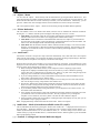
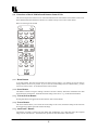
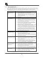
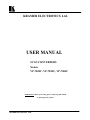
9.2 Functions of the SC-RM Infrared Remote Control Unit
This section will provide a brief overview of the individual functions of the buttons on the Remote Control Unit.
More detailed information about these functions is available in the previous section of this manual.
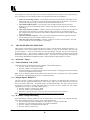
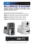
Below is a drawing of the SC-RM
STORE
RESET
1
2
3
4
5
6
AUTOTRAK
LEVEL
SIZE
POS
FILTER
L/CLICK
D/CLICK
R/CLICK
LOCK
MOUSE
PAN
ZOOM
U/SCAN
FREEZE
O/SCAN
9.2.1
Reset Button
As its name implies, this resets the unit back to the last-saved user settings. It is useful if you want to clear any
changes made to screen size or position. If you've saved an invalid setting to the non-volatile memory, you may
want to do a Factory Reset - as described elsewhere in this manual.
9.2.2
Store Button
This button is used for saving new settings to the Scan Converter's memory and will be remembered even after
the unit has been switched off. Just about all feature settings can be saved – e.g. Zoom Mode and Position.
9.2.3
U.Scan/O.Scan Button
Pressing this button will toggle between the Underscan and Overscan Modes.
9.2.4
Freeze Button
The Freeze function allows you to freeze the current image on the screen, and all the settings of the unit itself.
Pressing the freeze button again will unfreeze the image.
9.2.5
AutoTrack™ Button
AutoTrack™ is Kramer’s unique auto setup button that automatically sizes, shifts and centers the computer
image onto the video monitor. The details of its operation are described earlier in this manual.
Kramer Electronics Ltd.
17
Filter Button
9.2.6
This button will toggle between 4-Line and 6-Line Flicker Reduction Modes.
Size and Pos (Position) Buttons
9.2.7
These buttons allow adjustment of the Size and Position of the image on the video monitor in both the
Underscan and Overscan Modes, whichever is currently selected. You can then use the arrow keys to adjust the
horizontal and vertical size or position of the image being displayed.
Note – Ideally, the AutoTrack™ function should be run before making these adjustments, so that the unit knows
the precise size of the source image from the computer.
Only Size or Pos (Position) is active at any one time, but you can easily switch from one to the other.
Once adjusted, be sure and Store the setting for future use.
Zoom Button
9.2.8
The Zoom function allows you to view a section of the video image at twice the normal size. Enter this function
by pressing the ZOOM Button. Pressing ZOOM again will return you to the normal viewing size.
You can then 'Pan' around the image by using the Arrow Keys to slide the image around.
It is possible to Store this setting to make the unit start in the Zoom mode when powered up and be at a
particular pan position.
Other settings can be adjusted while in Zoom mode.
Note - you may need to press the Pan button to restore control over the Zoom position, after adjusting other
settings.
Lock Button
9.2.9
Pressing this button once will disable the Scan Converter's Front Panel Buttons. To re-enable them, simply
press the LOCK Button again. This setting can be stored (STORE Button), to prevent people from adjusting the
unit without the Remote Control.
Note - this feature is intended for use when other users should not disturb the settings of the unit.
9.2.10
Level Button
This button is not used on the Scan Converters covered in this manual.
9.2.11
Manual Set
This function should only be needed when the AutoTrack™ function has failed for some reason, or if the
computer image has a dark background around the edges that will not allow AutoTrack™ to work properly.
Please read the notes on AutoTrack™ and LEVEL adjustments in this section before adjusting the Manual Set
parameters, in case something else will solve the problem.
These adjustments allow manual selection of the area of the computer's image that is to be captured by the Scan
Converter and subsequently displayed on the video monitor. In effect, it is used to determine what goes into the
Scan Converter’s memory. This is not to be confused with the Size and Position adjustments mentioned earlier
in this section, which vary the parameters coming out of the Scan Converter’s memory. AutoTrack™ and
Manual Set are used to get the image correct going into the memory. If the entire image is never stored in
memory in the first place, it can never be read out.
Note - it is highly recommended that this method only be used when in the Underscan Mode or you will not
know if you have adjusted the values correctly.
Press AutoTrack™ on remote control twice (within 1.5s) - two 'beeps' will be heard.
Adjust Top and Left edge by pressing the appropriate Arrow Keys.
Press AutoTrack™ again.
Adjust Bottom and Right edge by pressing the appropriate Arrow Keys.
Press AutoTrack™ again - this will give a high beep to indicate that this has been saved.
Note - Manual Set Mode times out after 20 seconds, ignoring any changes made.
Kramer Electronics Ltd.
18
10
REMOTE MOUSE EMULATOR
10.1 Introduction
The Scan Converter has an RS-232 communications port that can be made to emulate a Microsoft® Serial
Mouse, and all the computer’s functions can be controlled from the Infrared Remote Control. This section
details how to setup and use this feature
10.2 Hardware Connection
Setup of this feature requires the connection of an RS-232 Cable by either of these methods:
Use a (Null Model) Serial Cable to connect the Scan Converter’s RS-232 Connector to the first spare
COM port on the computer (usually COM 2, but use COM 1 if it is available).
Disconnect the Mouse from the computer and use an RS-232 Sharer Cable to connect the computer to
the Scan Converter by plugging the Mouse back into the RS-232 Sharer Cable.
10.3 Scan Converter Setup
Make sure that RS-232 Mode is set to Mouse (and not 'Control') within the Advanced Menu of the On-screen
Display. (This is the default.)
10.4 Using the Mouse Emulator
The Scan Converter uses the computer's standard mouse driver, saving the need to load additional software.
Just turn your computer on with Scan Converter attached as described above.
If you are using an RS-232 Sharer Cable, both the existing Mouse and the Scan Converter’s Remote Control
will share the same COM port and software driver.
If you are using a separate COM port for the Scan Converter, the computer may recognize that a Mouse is
attached when booting up. If it does not, run “Add New Hardware” from the computer’s Control Panel to
automatically install the “Standard Serial Mouse” driver.
Use the Remote Control’s four Arrow Buttons to move your mouse pointer around the screen.
L.CLICK (left click) has the same function as a single left click of a standard mouse button.
D.CLICK (double click) has the same function as a double left click of a standard mouse button.
R.CLICK (right click) has the same function as a single right click of a standard mouse button.
10.5 Toggling Zoom/Pan and Mouse Modes
Both the Zoom’s Pan feature and Mouse Emulation feature can be used at the same time. You can toggle the
Arrow Key usage by pressing the Pan button on the Remote Control. If you find the Arrow Keys not
controlling the Mouse pointer, simply press Pan once to deselect the Pan Mode. Similarly, to reactivate PAN
Mode (to slide a zoomed image around the screen), press Pan again.
11
RS-232 COMPUTER CONTROL OF THE SCAN CONVERTER
11.1 Setup
All of the functions for the Scan Converter can also be controlled via a computer by using the RS-232 port on
the unit, an RS-232 Serial Cable and a terminal emulation program on the computer. Alternatively, the Scan
Converter can be controlled from your own custom software, provided that you have skills and resources to set
up a serial communications port in the programming language you are using.
The Scan Converter uses the following settings on its communications port:
8 bit data, no parity, 1 stop bit
No flow control
Set the Baud rate on the computer and the Scan Converter to the same value (usually 9600).
Instruction on how to set the above port settings can be found within your own systems help file or the help file
of the software you wish to use in sending commands. The following method is based on using a terminal
emulation program.
Kramer Electronics Ltd.
19
11.2 Sending Commands
Commands are sent over the RS-232 in one of two ways:
Send the 'adjust name' followed by = and a number (plus a carriage return) to alter any setting you see
displayed on the lower line of the LCD display. For example, if you were using a terminal emulator
program, you could type the following command to immediately set flicker reduction to 6-Lines:
Flicker Red = 6
Send just the 'adjust name' (plus a carriage return) to retrieve back the current value for a setting. For
example, typing the following returns the correct value back from the Scan Converter (e.g. '6'):
Flicker Red
11.3 Responses to Commands
The response from the Scan Converter can be one of three things:
? if something is not understood, e.g., an adjustment name is misspelled.
> if the command has been executed.
nnnnn (i.e., a five digit number from 0 to 99999, followed by a CR and LF) if a setting value is returned.
11.4 Notes on Sending Commands
Settings that are one of two values (e.g. NTSC or PAL), have to be sent as 0 or 1. 0 corresponds to the
Off or '-' state, and 1 corresponds to the On or '+' state.
You only have to send a maximum of 4 characters in order for the command name to be recognized, e.g.,
"Flicker Red = 2" could be shortened to "Flic = 2".
Spaces and line-feeds (ASCII code 10) are completely ignored.
The case is ignored (i.e., you can use upper case or lower case).
You must always send a carriage-return (ASCII code 13) at the end of your command or request.
The Scan Converter response should at most be within 20ms of the receipt of the carriage-return
character. Of course, delays due to slow baud rates will play a greater part than this.
The Scan Converter input buffer is limited to 32 bytes, so do not send any more characters (including
CR, LF, etc.) than this.
For more information on controlling the different functions, see relevant sections of this manual.
11.5 Restricting RS-232 Commands to Certain Units
If you have a number of units all connected to the same computer serial port, i.e., running in parallel, then you
can use the RS-232 ID feature to restrict certain commands to go to only certain Scan Converters. The
following points outline this method:
Make each 'RS-232 ID' setting unique to each Scan Converter, unless you want multiple units to respond
to the same commands (in which case, make them the same ID value). Default value is 0.
Send the command 'ID Restrict nnn' where nnn is the number of the Scan Converter you wish to control
(from 0 to 255).
Follow this with the commands you wish to send. Units where 'RS-232 ID' is not identical to the 'ID
Restrict' value will not respond to or acknowledge these commands.
To disable this feature, you have to make the RS-232 ID the same on all units (recommended value 0),
and of course set 'ID Restrict' to this value.
11.6 Changing Baud Rates
Details on how to change the Baud rate are in the Advanced Features section of this manual, but the relationship
between number and baud rate is given in the table below. Any number up to 191 can be selected, but only
certain Baud rates are generally used. The most common ones are outlined in the table below. For numbers not
included in the table, the Baud rate associated with those numbers can be found by using the following equation:
Baud =
223722
Number + 1
So to obtain the relevant number to be used:
Number = ( 223722 ) − 1
Baud
Kramer Electronics Ltd.
20
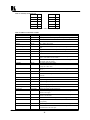
Table of commonly used baud rates
Baud Rate
No.
Baud Rate
No.
115200
1
14400
15
57600
3
9600*
22*
38400
5
4800
46
28800
7
2400
92
19200
11
1200
185
*22, Baud rate = 9600 is the default setting.
Table of all RS-232 commands available
Adjustment
Values*
ADC Ref.
100 to 200
Adj. Osc.
-200 to 200
AutoTrack
0 or 1
Comment
Adjusts maximum input RGB voltage.
Fine-adjusts subcarrier frequency when not genlocking.
Set to 1 to initiate AutoTrack
Baud Rate
0 to 191
Actual baud rate = 230400/(n+1)
Buttons
Off, On
Off = disable front-panel
CSync In Frq
0 to 140
CV Filter
DAC Ref.
0 to 40
40 to 120
Alter to suit incoming sync frequency when using a composite sync
input.
Applies a variable filter to Composite Video signals.
Brightness level
Flicker Red.
2, 4, 6
Lines of flicker reduction
Genlock
Off, On
H Phase
-18 to 18
H. Soften
ID Restrict
Off, On
n
Image Freeze
Off, On
Infra Red
Off, On
On=Unit will synchronize its output with incoming reference video
signal. (VP-705SC and VP-706SC)
Sets the unit's Horizontal phase, relative to reference signal.
(VP-705SC and VP-706SC)
On=Soften image horizontally.
Restricts RS-232 control only to those units which have RS-232 ID
already set to this value.
On=Image Frozen. Do not adjust any other settings when this is
active.
On=Infra red remote control is enabled.
Locked
Off, On
Overscan
Off, On
On=Disables all front-panel buttons and infra red remote control
functions
On=Overscan
Out H-Center:
n
Adjusts image left/right position
Out H-Width:
n
Adjusts image width
Out V-Center:
n
Adjusts image up/down position
Out V-Height:
n
Adjusts image height
Output Sig
Pan X Pos:
YUV, RGB
n
Pan Y Pos:
n
Reset
Off, On
Selects appropriate output signal type.
Adjusts Pan left/right position when in Zoom mode (higher value =
Panned to the right).
Adjusts Pan up/down position when in Zoom mode (higher value =
Panned to the bottom).
On=does a reset to user settings. Automatically goes back to Off.
RGB Term.
Off, Auto
RS-232
Auto=try to detect if monitor is attached, and terminate RGB
appropriately.
Mouse, Control If you change this to Mouse, RS-232 commands no longer function!
RS-232 ID
0 to 255
Kramer Electronics Ltd.
Sets the unit's RS-232 identification, where multiple units are
controlled from one serial port.
21
SC/H Phase
SC Ph. Shift
0 to 7
0, 180
SC Phase
-150 to 150
Sense
1 to 3
Selects subcarrier to H-sync phase when not genlocking.
Coarse-adjusts the final subcarrier phase shift.
(VP-705SC and VP-706SC)
Fine-adjusts the unit's colour subcarrier phase relative to reference
signal, when synchronizing to external source. (VP-705/6SC)
Adjusts the AutoTrack feature's sensing level
Sound
Off, On
Turns the internal speaker on or off.
Store Settings
-, *
Sets the current settings as the power-on default.
Sync In
Sync Out
Total Lines
0 to 3
0 to 3
Read only
0=VGA HV, 1=Grn+sy, 2=Pin 13, 3=Pin 15
0=-CS-CS, 1=+CS+CS, 2=-HS-VS, 3=+HS+VS
Returns number of lines in PC image, including vert blanking lines.
Vert. Freq
Read only
Returns vertical frequency of PC image (to nearest 1Hz).
VGA Bot/4:
n
VGA Left:
n
VGA Store
-, *
Tells the unit where the bottom of the image is within the PC signal.
(divided by 4).
Tells the unit where the left-hand edge of the image is within the PC
signal.
Stores the VGA settings, so they are used in the future.
VGA Top/4:
n
VGA Width:
n
Tells the unit where the top of the image is within the PC signal.
(divided by 4).
Tells the unit how wide the image is within the PC signal.
Video Std
NTSC, PAL
Sets the video standard
Y/C Delay
Zoom
0 to 3
Off, On
Adjusts luminance delay relative to chrominance.
Turns zoom mode on and off
*Where two text values are given (e.g. Off, On), the first relates to the setting used when '0' is sent to the unit,
and the second relates to the setting used when '1' is sent to the unit.
12
GETTING THE MOST FROM YOUR SCAN CONVERTER
These products are high quality scan converters with many functions and applications. The aim of this section is
to help you exploit some of these applications and functions to get the best possible results.
Hints & Tips
1. Use S-Video in preference to Composite Video, if your equipment has such an input. S-Video keeps
the color and brightness in a video signal separate, whereas Composite Video requires extra filters to
separate them electronically - these filters degrade the image.
2. Don't forget the ZOOM. If you have problems reading the small text, then selecting the ZOOM Mode
will make things much easier, especially if using the Composite Video output. This is particularly useful for
presentations.
3. Zoom Modes may require a different Flicker Reduction setting. Lowering the Flicker Reduction value
may help to increase legibility of small text.
4. The lower the graphics resolution and refresh rate, the better the image quality. All scan converters
store the computer image to be converted to video in their own internal memory, and to do so the computer
image has to be 'sampled' many times during each scan-line. Each sample stores one pixel of information
in the memory. The number of samples taken is proportional to the image quality - i.e. the more samples
the better. Higher graphic resolutions take less time to display each scan line than lower ones, so it means
that there will be more samples per line for lower resolution modes because there's more time for more
samples to be taken, therefore, a better image quality will result.
5. The lower the graphics resolution, the better the 'vertical' image quality. TV's have a fixed number of
lines available for displaying pictures - for PAL it is 576, for NTSC it is 480, although some of these are off
the top and bottom edges of the screen. So, the more scan lines a graphics resolution has (e.g.. an 800x600
resolution has 600 scan lines), the more difficult it is for your Scan Converter to squeeze all these lines into
Kramer Electronics Ltd.
22
the limited number available on the TV. So lowering your graphic resolution will help improve image
quality. (Remember to run AutoTrack after you change the resolution).
6. If you experience line dropping, use a higher Flicker Reduction setting. For lower resolutions like
640x480, you may even need to reduce the Flicker Reduction setting to 2-Line. At very high resolutions
like 1280x1024, you may wish to consider using a Scan Converter with 6-Line Flicker Reduction ability,
like the VP-703SC.
7. Cables and Connectors. Using good quality cables and connectors like the ones supplied with your
Scan Converter unit and ensure that all connectors are properly connected to help maintain a high picture
quality.
8. Designing your Display or Presentation. When setting up an image for display or putting together your
presentation, keep in mind that people might have to view it from a distance. Using a font that is well
defined, graphics and pictures that are uncluttered will all add to the legibility of your display or
presentation. Try to make text well spaced and larger than you normally use. Think about the colors you
are going to use. Colors that standout from each other are better for viewing at a distance. As mentioned
earlier, choosing the right screen resolution will also add to the clarity and quality of your display. It is
worth spending some time experimenting with different screen resolution settings, which will optimize your
Scan Converter to its full potential.
9. Freeze function. This function is useful if you wish to change to another image or layout while
maintaining an image on your video monitor. For example, when you wish to change from a program that
is displaying text to a program that displays a graphic. Before you close the text display program, Freeze
the image on the video screen that you are using. You are then free to change to the graphic image
program. Once this is done, you can unfreeze the image on the video screen, which will then display your
new image. People watching the video monitor would have only seen the text image followed by the
graphics image and they would not have seen you close one program and open another.
13
TECHNICAL DATA
13.1 Computer Input
Input to the Scan Converter is via an HD-15 connector.
Pin
1
2
3
4
5
6
7
8
Use
Red 0.7v max. / 75 Ohms
Green 0.7v max. / 75 Ohms
Blue 0.7v max. / 75 Ohms
ID 2, passed to PC monitor pin 4
Ground
Red ground
Green ground
Blue ground
Pin
9
10
11
12
13
14
15
Use
Passed to PC monitor pin 9
Ground
Ground
ID 1, passed to PC monitor pin 12
Horizontal Sync TTL
Vertical Sync TTL
Passed to PC monitor pin 15
13.2 Fuse Replacement
The Scan Converter is double-fused for added protection. The main AC fuse is located next to the On/Off
Switch on the rear panel and is easily accessible. There is also a DC fuse on the main circuit board inside the
unit, however, this rarely needs replacing. If replacement is necessary of either fuse, be sure to use the same
type and size as the original.
Kramer Electronics Ltd.
23
14
TROUBLESHOOTING
If the recommended actions still do not result in satisfactory operation, please consult your Kramer Dealer.
Before seeking technical assistance, if the problem is image related, please try to find out the screen resolution
and refresh rate being used from the computer and if the problem only affects one particular resolution.
Problem
The picture on the video
display is black and
white.
There is no picture on
the video monitor.
There is no picture on
the computer monitor.
The display on the TV
has a huge border around
it.
Remedy
1. If you are using the S-Video or Composite outputs, then make
sure that all these cables are connected correctly.
2. Make sure that the Scan Converter is adjusted to the right video
standard PAL/NTSC (The procedure to change this is found
elsewhere in this manual).
3. Ensure that the color controls on your TV or video monitor are all
set correctly.
1. If you're using the unit with a laptop computer, make sure the
laptop is set to enable an external display device. Some laptops
automatically detect external video connections, but others will
need setting up to do so. This is often accomplished by pressing
two keys simultaneously on the keyboard.
2. If the Power LED on the Scan Converter is off, ensure that the
proper AC Power is being supplied to the unit and check the fuse
(The procedure located elsewhere in this manual).
3. If the Power LED is on: a) Check that the monitor output from the
computer is connected to the Scan Converter’s VGA IN
connector, b) Check that the output you are using from the Scan
Converter is also connected at the unit and the video monitor, and
c) Check that your video monitor is switched on and set to the
correct input (AUX or A/V is selected), also make sure that the
Brightness and Contrast on the video monitor are set correctly.
4. Don’t forget that when the Scan Converter is in the YUV Mode,
all other video outputs will be blanked out.
1. Check that the VGA output from the computer is connected to the
Scan Converter’s VGA IN connector.
2. Check that the computer monitor is connected to the VGA OUT
connector on the back of the Scan Converter.
3. Check that your computer monitor is turned on and the Brightness
and Contrast are set correctly.
1.
2.
The unit does not
respond to the Infrared
remote control.
1.
2.
3.
There is excessive
flicker on the TV.
1.
2.
Kramer Electronics Ltd.
This usually means that you are using a laptop computer at a
resolution lower than the laptop's own screen. When this
happens, the laptop fits the smaller resolution into the larger with
a border around the edge.
Since the laptop's screen is of a fixed resolution, the only two
solutions are: a) change the resolution you're running at to match
the laptop's own internal screen, or b) disable the laptop's own
screen, so you just see the image on the video monitor.
Ensure that there are batteries in the Remote Control unit are
correctly inserted and that they have enough charge left.
Make sure that there is no obstruction in front of the Scan
Converter's Front Panel Infrared Window.
Ensure that the Scan Converter is set for control from the IR unit
(The procedure to change this is found elsewhere in this manual).
Try using a different Flicker Reduction Filter setting (The
procedure to change this is found elsewhere in this manual).
Turning the contrast down and the brightness up on the video
monitor can also have a large effect on flicker.
24
The TV image is
distorted.
1.
2.
3.
Some colors come out
wrong on the video
monitor.
1.
2.
How can I reduce
smearing?
1.
2.
How do I use the unit
with a VCR?
The recorded image is
poor.
1.
2.
1.
2.
The mouse emulation
isn't working.
1.
2.
3.
Kramer Electronics Ltd.
This often occurs where some of the areas of the image are very
dark and others are very bright. These extreme changes in the
image are difficult for your video monitor to deal with.
Try adjusting the contrast and brightness settings on your video
monitor to rectify the problem. On some older or very
inexpensive TVs this effect is unavoidable, as they may not be
designed with computer images in mind and, therefore, show
'bowing' at the sides for some graphic images. The only solution
is to adjust the brightness and contrast on the TV - the Scan
Converter is not at fault and cannot correct problems with these
type TVs.
If the problem still persists it may be due to the screen size
settings. Try adjusting the image and its position on the screen.
Try altering the color (saturation), hue (tint), contrast and
brightness settings on your TV or video monitor. These are
usually set up for viewing TV programs or video, which is very
different from viewing computer graphics.
If you are using the RGB video output from the Scan Converter,
make sure that the cable is correctly attached to both it and the
video monitor.
Smearing usually occurs on Composite Video connections, and is
generally unavoidable, unless you can switch to using S-Video or
RGB connections (See connection details elsewhere in this
manual). It occurs because the luminance and color information
is combined as one signal and the two parts have to be
'bandwidth-limited' to avoid them interfering with each other.
Using good quality video cable will help towards reducing this
affect.
Connect one of the Scan Converter’s video outputs to the VCR's
input. You won't be connecting to the Antenna connector on the
VCR, but rather, to one of the VCR's AUX (Auxiliary) inputs, so,
therefore, you must elect the proper setting on the VCR’s input
selector (often it's channel 0, AUX 1, AUX 2, etc).
Follow the VCR’s recording instructions.
Standard VHS videos are not very good at recording the fine
detail present in computer graphics. S-VHS decks offer much
better quality, while professional decks will be even better.
Color smearing is usually the first thing that causes a problem, but
this is because your VCR isn't capable of recording the picture in
its full resolution. Try lowering the computer screen resolution;
this will bring the image more in line with what your VCR is used
to dealing with.
Check that the RS-232 cable is connected correctly to both the
RS-232 port on the back of the Scan Converter and to the Serial
Port that the computer uses for the mouse.
Check that the Scan Converter is setup for the Mouse and not
Serial control. Check that the Infrared Remote Control has good
batteries installed and that the Scan Converter is configured to
work from the remote.
The Scan Converter uses the standard Microsoft® Serial Mouse
driver. It will not work with other mouse drivers. If problems
arise, it is recommended that the computer be started up with its
normal mouse connected, once the computer has finished booting
up and the mouse confirmed working, it can be swapped over
with the Scan Converter’s RS-232 cable.
25
15
LIMITED WARRANTY
Kramer Electronics (hereafter Kramer) warrants this product to be free from defects in material and
workmanship under the following terms.
HOW LONG IS THE WARRANTY
Labor and parts are warranted for three years from the date of the first customer purchase.
WHO IS PROTECTED
Only the first purchase customer may enforce this warranty.
WHAT IS COVERED AND WHAT IS NOT COVERED
Except as below, this warranty covers all defects in material or workmanship in this product. The following are
not covered by the warranty:
1.
2.
3.
Any product which is not distributed by Kramer or which is not purchased from an authorized Kramer
dealer. If you are uncertain as to whether a dealer is authorized, please contact Kramer at one of the agents
listed in the web site www.kramerelectronics.com.
Any product, on which the serial number has been defaced, modified or removed.
Damage, deterioration or malfunction resulting from:
a)
b)
c)
d)
e)
f)
g)
Accident, misuse, abuse, neglect, fire, water, lightning or other acts of nature.
Unauthorized product modification, or failure to follow instructions supplied with the product.
Repair or attempted repair by anyone not authorized by Kramer.
Any shipment of the product (claims must be presented to the carrier).
Removal or installation of the product.
Any other cause, which does not relate to a product defect.
Cartons, equipment enclosures, cables or accessories used in conjunction with the product.
WHAT WE WILL PAY FOR AND WHAT WE WILL NOT PAY FOR
We will pay labor and material expenses for covered items. We will not pay for the following:
1.
2.
3.
Removal or installations charges.
Costs of initial technical adjustments (set-up), including adjustment of user controls or programming.
These costs are the responsibility of the Kramer dealer from whom the product was purchased.
Shipping charges.
HOW YOU CAN GET WARRANTY SERVICE
1.
2.
3.
To obtain service on you product, you must take or ship it prepaid to any authorized Kramer service center.
Whenever warranty service is required, the original dated invoice (or a copy) must be presented as proof of
warranty coverage, and should be included in any shipment of the product. Please also include in any
mailing a contact name, company, address, and a description of the problem(s).
For the name of the nearest Kramer authorized service center, consult your authorized dealer.
LIMITATION OF IMPLIED WARRANTIES
All implied warranties, including warranties of merchantability and fitness for a particular purpose, are limited
in duration to the length of this warranty.
Kramer Electronics Ltd.
26
EXCLUSION OF DAMAGES
Kramer’s liability for any defective products is limited to the repair or replacement of the product at our option.
Kramer shall not be liable for:
1.
2.
Damage to other property caused by defects in this product, damages based upon inconvenience, loss of
use of the product, loss of time, commercial loss; or:
Any other damages, whether incidental, consequential or otherwise. Some countries may not allow
limitations on how long an implied warranty lasts and/or do not allow the exclusion or limitation of
incidental or consequential damages, so the above limitations and exclusions may not apply to you.
This warranty gives you specific legal rights, and you may also have other rights, which vary from place to
place.
Note - All products returned to Kramer for service must have prior approval. This may be obtained from your
dealer.
16
COMPLIANCE NOTICE
This equipment has been tested to determine compliance with the requirements of:
EN 55022
EN-50081
CFR-47
CE emissions standards, Class B
Generic Immunity standard for residential, commercial and light industrial)
FCC Rules and Regulations:
Part 15- “Radio frequency devices:
Subpart B- Unintentional radiators
CAUTION!
⌦
⌦
⌦
Servicing the Scan Converter can only be done by an authorized Kramer technician. Any user who makes
changes or modifications to the unit without the expressed approval of the manufacturer will void user
authority to operate the equipment.
Please use recommended interconnect cables to connect the machine to other components.
When used, it is assumed that the unit is grounded by normal means (e.g. via the computer video input
cable, rack-mount chassis ground, or video output cable to display device). Use of the equipment without
any form of grounding may affect radiated emissions, but will not affect the product's safety.
Kramer Electronics Ltd.
27
The list of Kramer distributors appears on our web site:
www.kramerelectronics.com
From the web site it is also possible to e-mail factory headquarters.
We welcome your questions, comments and feedback.
KRAMER ELECTRONICS, LTD.
3 Am VeOlamo Street. Jerusalem 95463, Israel Tel: (972-2)-654-4000. Fax: (972-2)-653-5369
e-mail: [email protected]