1
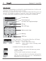
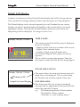
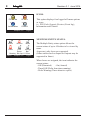
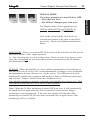
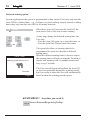
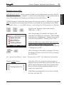
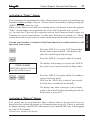
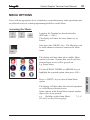
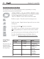
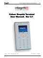
Integriti. Colour Graphic Terminal User Manual. 1 Colour Graphic T erminal Terminal User Manual. R Rev ev 3.1 © 2013 - 2014. Inner Range Pty. Ltd. Part Number: 636000U 2 Integriti. Revision 3.1 June 2014. SYSTEM DETAILS CUSTOMER: ............................................................................................... SITE ADDRESS / LOCATION: ....................................................................... ............................................................................................... PHONE: ........................................ FAX: ............................. E-MAIL ................................................................................. INSTALLED BY: ............................................................................................. ............................................................................................... PHONE: ........................................ FAX: ............................. E-MAIL ................................................................................. MAINTENANCE & SERVICE: .................................................................... ............................................................................................... PHONE: ........................................ FAX: ............................. E-MAIL ................................................................................. MONITORED BY: .......................................................................................... ............................................................................................... PHONE: ........................................ FAX: ............................. E-MAIL ................................................................................. 3 Colour Graphic Terminal User Manual. CONTENTS The Keypad. .......................................................................................... 4 Default LCD Display ............................................................................. 7 Indicator Lamps. .................................................................................... 9 If Used. [ ] [ ] [ ] [ ] [ ] [ ] [ ] [ ] [ ] [ ] [ ] [ ] USER ALARM SYSTEM OPERATIONS ........................................ System Status Messages. ....................................................................... Logging On............................................................................................ Turning Area/s OFF. .............................................................................. Deferred Arming .................................................................................... Turning Area/s ON. ............................................................................... Activating a Panic Alarm. ..................................................................... Activating a Duress Alarm. ................................................................... Acknowledge an Event or Alarm. ......................................................... 10 10 11 12 14 15 17 17 18 USER SYSTEM STATUS & CONTROL OPERATIONS .............. User Action Control. .............................................................................. View Alarm Review information........................................................... View System Information. ..................................................................... 19 19 21 22 MENU OPTIONS ................................................................................ 23 Accessing the Menu. ............................................................................. 23 Keypad Functions in the Menu. ............................................................ 24 INNER RANGE recommends that all INTEGRITI systems are installed & maintained by FACTORY CERTIFIED TECHNICIANS. For a list of Accredited Dealers in your area refer to the Inner Range Website. http://www.innerrange.com Disclaimer While every effort has been made to ensure the accuracy of this manual, the manufacturer and/ or it’s agents assume no responsibility or liability for any errors or omissions. Due to ongoing development and product improvements, the contents of this manual are subject to change without notice. Comments relating to this manual should be sent to [email protected] Contents Integriti. 4 Integriti. Revision 3.1 June 2014. The Keypad. Operations & programming are performed by using the function keys, fixed keys and scroll wheel. You may only press one key at a time. Each time a key is pressed, a short “beep” is sounded to indicate that the key press was accepted. (The Installer can disable or change the volume of the beeping if required) A ‘crash’ sound will be sounded if a key press is not accepted or is not allowed. Function keys Scroll wheel and up, down, left, & right arrow keys OK key ON / OFF keys Alpha-numeric keys END key HELP key FUNCTION KEYS. The operation of these keys will change according to the screen currently in use. e.g. Left Key: Cancel / Menu / Back / Done Right Key: Logon / Delete / Search / Selecting a mode of operation. COMMON FUNCTION KEY OPERATIONS <Cancel>. Allows you to cancel a PIN code entry without logging an attempt. e.g. If you make a mistake and want to start again. <Menu>. Accesses the Menu for information and operations other than Area On/Off, Door Access, etc. A limited Menu is displayed if you are not logged on. Integriti. Colour Graphic Terminal User Manual. 5 <Back>. Return to the previous screen. <Done>. Returns to the Logged Off Menu. <Delete>. Allows you to delete the last character entered. e.g. If you make a mistake while entering your PIN code. <Search>. Switches to the Alpha-numeric search mode for selecting an entity to control or edit. ARROW KEYS AND SCROLL WHEEL. The SCROLL WHEEL or the <UP> and <DOWN> arrow keys are used to scroll up and down through lists of available items to view, control or edit, (e.g. Areas, Review messages, Users, etc), and to adjust numerical values (e.g. In a Timer). The Scroll Wheel can also be used to move the cursor left or right. The <LEFT> arrow key will move the cursor to the left. The <RIGHT> arrow key will move the cursor to the right. The <OK> key must always be pressed after you have entered your secret PIN code (Unless performing a “Quick Arm or Disarm” operation). You have 10 seconds to press the <OK> key after you have completed entering the code. If PIN codes are used to unlock doors, pressing the <OK> key again will perform the Door unlock operation on the Door associated with the Terminal. On Terminals that are programmed ONLY for Door Access control, the <OK> key may not need to be pressed twice. (In some cases, the <OK> key may be programmed to unlock a door without a PIN code being used. e.g. In low security TERMINAL <Logon>. Displays the Logon screen. 6 Integriti. Revision 3.1 June 2014. periods, or when the Terminal is on the inside of an Exit Door.) OFF / ON. Used to turn Off or turn On, the Item named on the Display at the time. e.g. Area, Area List, User Action, etc. ALPHA-NUMERIC keys. Used for entering your secret PIN code. You have 10 seconds to enter each digit, and must press the <OK> key when complete. This sequence is required before most operations can be performed. These keys can also be used to search for an item by name. e.g. A User to edit or an Input to Isolate. HELP. Can be pressed at any time to display a “Help message” about the current operation being performed. The <END> key is used when you have finished performing the required operations. NOTE: Keypad keys also have other functions when you are selecting, viewing, controlling or editing items in the menu. Details of the keypad functions when you are in the menu are provided in the “Menu Options” section of this manual. The system may be programmed to limit the operations available at some Terminals. Integriti. Colour Graphic Terminal User Manual. 7 Default LCD Display. The Default display can be selected separately for each Terminal in your system. Settings can only be programmed by the Installer, who can also advise you on the appropriate options. If no specific Default Display option has been chosen, the Integriti logo will be displayed. See image on front cover. Monday, 18th Apr 11:25am 12:48 PM Friday, 16th Aug 2013 TIME & DATE. The current system Time & Date may be displayed in one of 3 formats: - Single text line at the top or bottom of the screen. - Digital Clock with date below. - Analogue Clock in top left-hand corner. (The Text and Digital Clock options are shown opposite) This is useful in systems that generate Time-OnSite reports to show the Date & Time being logged. SINGLE AREA STATUS. Monday, 18th Apr 11:25am Library is Off Integriti by Inner Range Menu Temp 25.3°C Logon This option allows the name and current status of a single Area to be displayed. This is useful when the Terminal only provides control of one Area. LCD MESSAGES. This feature provides one or more customized messages that are appropriate for the particular Site and/or the particular Terminal. e.g. -The Monitoring Station’s Phone number. -The Installer’s Phone number. -“Welcome to <your company name>”. TERMINAL A number of options are offered for the Default display that will be shown when no User operations are being performed, and no other messages are being displayed. Integriti. 8 1 Revision 3.1 June 2014. ICONS. 2 PIN Code Review 3 4 Information Control Temp 25.3°C This option displays four logged-off menu options as icons. i.e. PIN Code (Logon), Review (Event log), Information and Control. Logon MULTIPLE ENTITY STATUS. Admin Kitchen Bistro Cellar Cool Room Lounge Bar Monday, 18th Apr 11:25am Menu Temp 25.3°C Logon The Multiple Entity status option allows the current status of up to 6 Entities to be viewed by name. At present, only Areas are supported. (Other entities such as Inputs or Outputs may be supported in future) When Areas are assigned, the icon indicates the current status; - Off (Disarmed) - On (Armed) - Timed Off (Defer Arm timer running) - Defer Warning (Timer about to expire) Integriti. Colour Graphic Terminal User Manual. 9 The Indicator Lamps. The settings can only be programmed by the Installer, who can also advise on the appropriate options for your system. When programmed for “Area Array”, the lamps will indicate the status of up to 8 sequential Areas in the following manner: Green or Off = Area Off (Disarmed) Green Slow Flash = Entry or Exit Timer running. Red = Area On (Armed) Red Fast Flash = Alarm in this Area. Yellow Slow Flash = Deferred Area Arm. Yellow Fast Flash = Deferred Area Arm Warning (About to Arm). Lamp No: 1 2 3 4 5 6 7 8 The lamps may have been programmed to indicate other conditions or the status of other entities. If so, please record their purpose here: Lamp 1 ........................................... Lamp 5 ........................................... Lamp 2 ........................................... Lamp 6 ........................................... Lamp 3 ........................................... Lamp 7 ........................................... Lamp 4 ........................................... Lamp 8 ........................................... TERMINAL Eight multi purpose lamps are provided for quick indication of Area and Alarm Status, and/or other conditions. 10 Integriti. Revision 3.1 June 2014. USER OPERATIONS User operations are the basic day-to-day operations performed on the system. These include: Turning Areas ON and OFF. (Arming and Disarming) Acknowledging Alarm messages. Accessing Doors and/or Lifts Viewing Area Status information and reviewing the Event Log. Controlling Outputs (Turning User Actions ON and OFF) The system is designed for simple operation, providing straightforward procedures, and display prompts in plain English text. However, if a User is unsure of what to do next, a simple press of the <HELP> key provides additional assistance. Many User operations begin with the same simple procedure. The User logs on to the Terminal by entering their secret PIN code followed by the <OK> key. The User is then verified and will be able to perform any operations allowed. The LOGON procedure is described on the following page followed by the common operations. System Status Messages. System operation is continuously monitored for problems and special conditions. Your sytem may be configured to display a status message when any of these problems or conditions exist. These messages are displayed on the nominated Terminal/s and will remain on the display until the condition is rectified. The table below describes the messages currently provided. For messages not listed here, please consult the Installer. You will probably require the Installer to rectify most of these conditions. MESSAGE DESCRIPTION Input(s) AC fail One or more Modules have lost AC power. If accessible, check AC power cord/plug-pack is connected & switched on. Input(s) low batt One or more Modules have low battery voltage. Input(s) batt test fail One or more Modules have failed a battery test. Input(s) cabinet tamper An unauthorised attempt has been made to open or remove a Module enclosure. Input(s) LAN comms problem One or more Modules are not communicating with the Control Module. There may be cable damage or a Module problem. Input(s) isolated One or more inputs have been isolated. If isolated due to a fault, the device or cabling may require service. ...Module(s)... Any Module messages such as "Module(s) missing" or "Module(s) unsecured" should be reported to the Installer. Integriti. Colour Graphic Terminal User Manual. 11 LOGON LOGON. Logging on is the first step performed in many operations. - Enter your secret PIN Code using the digit keys, then press the <OK> key. Each digit pressed will be displayed as an asterisk (*) character. , User code entry Enter your PIN If you make an error while entering your PIN code, press <Delete> to delete the last character entered, or the <Cancel> or <END> key to start again. ******** Cancel OK=Accept Delete Good Morning Robyn If there are no messages to be acknowledged, the Display may first greet and identify you. Note: The greeting may be disabled if required. If there is a message to be acknowledged, refer to “Acknowledge an Alarm”. Area Control Admin Sales Counter Warehouse Board Room Training Room Menu OK=On The Area Control screen is now displayed, with the first Area (or Area List) that you are allowed to control highlighted, and a text prompt for the relevant action on that Area, shown at the bottom of the screen. i.e. “OK=On” Area Lists When your operations are complete, you should Logoff the Terminal by pressing the <END> key. If the <END> key is not used, the Terminal will log off automatically within a short time. 12 Integriti. Revision 3.1 June 2014. Turning Area/s OFF. Once you have Logged on to a Terminal, and can view the Area status, you may perform the Area OFF or ON operations. Remember: You have a limited time to turn an Area OFF once you have entered the Area (Usually 30-90 seconds). Ask the Installer for the Entry time used in your system. - , Area Control Admin Sales Counter Warehouse Board Room Training Room Menu OK=Off or Admin Logon to the Terminal as described earlier. (PIN code + <OK>) After the greeting (if enabled), the display shows the Area Status etc. as before. The currently selected Area is highlighted. To select another Area see “AREA SELECTION” below. Area Lists After selecting an Area that is currently On, turn the displayed Area (or Area List) OFF by pressing the <OFF> key. The icon and text colour will alter accordingly to indicate that the operation was successful. NOTE: Quick Arm/Disarm. Your system may be configured to allow a nominated Area to be controlled simply by entering your PIN code, then the OFF or ON key. i.e. OK key not required. -AREA SELECTION. You may select other Areas by using the SCROLL WHEEL or the <UP> / <DOWN> Arrow keys. Integriti. Colour Graphic Terminal User Manual. 13 The Display mode can be toggled between AREAS, AREA LISTS and 24 HOUR, by pressing the right hand FUNCTION key. Once in the selected mode, Area/Area List selection and control is the same as described previously. Please read additional information below: AREA LISTS. Allows you to turn OFF all the Areas in the selected List, that you are allowed to control, with a single operation. i.e. You can select any Area List in the system. However, only Areas that are in the Area List selected and are also Areas that you have permission to turn off (disarm), will be turned Off. 24 HOUR. Allows the Installer, or a User with the appropriate level of authority, to turn the 24Hr part of an Area Off, so that maintenance or changes can be performed on equipment or devices (detectors etc.) in the system. The 24Hr part of an Area continuously monitors the equipment and inputs for faults or deliberate interference and activates “Tamper” alarms when these conditions occur. Note that this operation is normally restricted to the Installer &/or Owner only. Most Users in the system will NOT have access to this operation. Note: When the 24 Hour monitoring is turned Off in an Area, it will automatically be turned back On again when the Area is turned ON to ensure that Tamper monitoring is not compromised. If the Area was already Off when the 24Hr monitoring was turned Off, the Area must be turned back on again before 24Hr monitoring will be re-enabled. Area On/Off DISPLAY MODE. If you have permission to turn ON &/or OFF: - More than one Area. - The 24 Hour (Tamper) part of an Area. 14 Integriti. Revision 3.1 June 2014. Deferred Arming option. In some applications the system is programmed so that certain Users may only turn the Area Off for a limited time. e.g. A cleaner or guard working outside normal working hours may only turn the Area Off for 60 minute intervals. When these types of Users turn the Area Off, the icon shows Area is Off with a timer running. Cellar - , , or At any stage during the deferred arming time, the User can: - Turn the Area Off again, to re-start the timer, or - Turn the Area back On and cancel the timer. The sytem also allows a warning timer to be programmed for each Area that has a deferred arming timer. When the deferred arming timer is about to expire, the warning timer will start causing the Terminal to display this warning with a countdown timer and beep every 2 seconds. Cellar Timer Warning, Area will turn on in 49 Seconds Logon The User can still logon and perform the Area Off or Area On operations during this warning period, but if no action is taken the Area will automatically turn On when the warning period expires. REMEMBER !! Any time you need it, is as close as the press of a key. Integriti. Colour Graphic Terminal User Manual. 15 Turning Area/s ON. If Walk Testing is enabled on your system, the same procedure is followed except that after the initial test to ensure that all Zones are Sealed, the system then enters Walk Test mode. Refer to “Area Walk Testing” in the Integriti LCD Terminal User Manual. - Logon to the Terminal as described earlier. (PIN code + <OK>) , Area Control Admin Sales Counter Warehouse Board Room Training Room Menu OK=On Area Lists or After the greeting (if enabled), the display will show the Area Status etc. as before. The currently selected Area is highlighted. Another Area can be selected as described in “Turning Area/s OFF”. If you are allowed to control more than one Area, or the 24 Hour (Tamper) part of an Area, the DISPLAY MODE can be changed as described in “Turning Area/s OFF”. After selecting an Area that is currently Off, turn the displayed Area (or Area List) ON by pressing the <ON> key. See “Quick Arm/Disarm” under “Turning Area/s OFF” for additional information. Display briefly shows: Turning Admin On After the <ON> key is pressed, this message is displayed briefly while the system tests the state of all the inputs allocated to the Area to ensure that they are in the Sealed condition and the Area is ready to be turned ON. If all Zones programmed to be tested are Sealed, the Area will turn ON. Area On/Off IMPORTANT NOTE: Some systems in high security applications may have the PreArm “Walk Test” feature enabled. In most systems this feature is not enabled and the Area ON procedure will simply be performed as described below. Integriti. 16 Revision 3.1 June 2014. Admin Timer Exit Delay, Area will turn on in 37 Seconds Remember: You have a limited time to exit the Area once you have turned it ON. (Usually 30-90 seconds. Ask the Installer for the time used in your system) Your Graphic Terminal may be configured to display this countdown timer and/or sound a warning during the Exit Delay period. Logon When the operation is complete the display will return to the Area status display. The icon and text colour will alter accordingly to indicate that the operation was successful. Admin OR Unsealed Inputs Fire Door Reed Switch Cancel Isolate , or then After pressing the <ON> key, the display may show a message like this. It means that any items displayed are either in an alarm state or faulty, and the Area will not turn ON. e.g. A detector or it’s cabling have been damaged. A door or window has been left open. Try to rectify any problems before trying again. If you are unable to rectify a problem, you have 2 options: 1) You may be allowed to ISOLATE the item while the “Unsealed Inputs” message is displayed. Press the <Isolate> key, select the Input to Isolate using the SCROLL WHEEL, then <OK> to confirm the Zone Isolation operation. When complete, press <Done> to proceed with the Area On operation. 2) Press <Cancel> to cancel the Area On operation. NOTE: Inputs isolated in this way are automatically de-isolated when the Area is turned OFF. Integriti. Colour Graphic Terminal User Manual. 17 Activating a “Panic” Alarm. Consult your Installer to detemine if the Panic function is enabled and how it will operate in your system. Press the <HELP> key at any LCD Terminal that has the Panic option enabled. The display will show the normal logon help message. Press the <HELP> key again within 30 seconds, PANIC ALARM The display will prompt you to press the <HELP> key again if you want to activate the Panic alarm. PRESS HELP AGAIN FOR PANIC Press OK or END to cancel. or Press the <HELP> key again within 30 seconds to activate the Panic alarm, OR Press the <END> key to abort if you pressed the Help key a second time accidentally. The display may show a message, or may simply return to the normal display depending on how the Panic alarm is processed. Activating a “Duress” Alarm. Your system may be programmed to allow a Duress alarm to be activated if you are being forced to perform operations at a Terminal against your will. Duress is activated by simply entering a special PIN Code instead of your normal PIN Code, when logging on to the LCD Terminal. Consult your Installer for details. Panic/Duress Your system may be programmed to allow a Panic alarm to be easily activated from any Terminal without needing to Log on. A Panic Alarm is activated by simply pressing the <HELP> key three times in a row. When a Panic alarm is activated, the resulting action will depend on how the optional “Panic” System Inputs are programmed for each of the Terminals in the system. e.g. In some sites, Panic may be required to activate local Sirens and send a report to a Computer in a local Control Room. In other sites Panic may be treated as a “Silent” system alarm with a report sent to a remote monitoring station and no local action at all. 18 Integriti. Revision 3.1 June 2014. Acknowledge an Event or Alarm. Alarm or Event messages must be acknowledged by a User with the appropriate authority. These messages provide precise information of the type of event, the Area it has occurred in, and the Zone Input or System Input that caused the alarm. Had Event in Kitchen A message may be displayed on the Terminal indicating which Area the Event has occurred in. Kitchen had an Event - Logon to the Terminal as described before. (PIN code + <OK>) , Events in Kitchen Heat Rise Detector had Alarm Accept All OK=Ack Later The display will show the specific details of any Events in this Area that have not been acknowledged. Select an Event using the SCROLL WHEEL, note the details, then press: - The <OK> FUNCTION key to acknowledge the selected message, or - The <Accept All> FUNCTION key to acknowledge all messages displayed, or - The <Later> FUNCTION key to postpone acknowledgement of the alarm. If there are other Areas that have had an event, the next Area event messages will be displayed until all messages have been acknowledged or postponed. The display will then show the Area Status display to allow you to continue with your operation. e.g. Turn the Area OFF. Integriti. Colour Graphic Terminal User Manual. 19 SYSTEM STATUS AND CONTROL OPERATIONS User Action Control. Individual Terminals may be programmed to allow Users to control specified Actions without needing to Log on to the Terminal. User Actions can be turned On, turned Off or turned On for a timed period in minutes or seconds. Typical applications include lighting, heating, pool pumps, speaker switching, irrigation, etc. Selecting a User Action to View or Control. , 1. If this option is enabled, simply press the <Menu> FUNCTION key, then the <1> key. Alternatively, press the <Menu> FUNCTION key, highlight the “Control” icon using the SCROLL WHEEL, then press the <OK> key. User Actions Garden Lights Outdoor Speakers Pond Fountain Back OK=On The display shows the current status of up to five User Actions in alphabetical order. Timed Use the SCROLL WHEEL or <UP> and <DOWN> Arrow keys to select a User Action to control. Alarm Ack. NOTE: Access to some User Actions may be limited to particular Users. These User Actions can only be controlled by Users with access to the Control Menu. <MENU>, <9>. After logging on and selecting the Menu option, control operations will be the same as described below. Integriti. 20 Revision 3.1 June 2014. Controlling the User Action. or When the desired User Action is selected (i.e. Highlighted in the list), press: - <ON> to turn it On. - <OFF> to turn it Off. - <OK> to toggle the state. - <Back> FUNCTION key or <END> to return to the default display. - <Timed> FUNCTION key to enter a User Action “On time”. or or User Actions Garden Lighting 0Hr 00Min 00Sec If “Timed” is selected, use the <LEFT> and/or <RIGHT> ARROW keys to position the cursor on the time digit you wish to edit, then use the SCROLL WHEEL or the ALPHA-NUMERIC keys to enter the required value. Mode: Timed On Cancel OK=Start Set Mode A period of up to 4 Hours may be entered. Periods are accurate to +/- 1 second. The <Set Mode> FUNCTION key can be used to choose the timer mode. Options will vary depending on the type of entity being controlled. or When the timer period is entered, and mode selected, press <OK> to start the timed action, or <Cancel>. The display will then return to the User Action list. The icon and text will be updated to indicate the new Entity state. Integriti. Colour Graphic Terminal User Manual. 21 View Alarm Review information. Individual Terminals may be programmed to allow Users to review the Event log information without needing to Log on to the Terminal. If this option is enabled, simply press the <Menu> FUNCTION key, then the <2> key. , 2. Alternatively, press the <Menu> FUNCTION key, highlight the “Review” icon using the SCROLL WHEEL, then press the <OK> key. Menu 1 2 Control Review 3 4 Aircon Information Review Apr22 17:57:09.4 Xmit Alarm Activat Apr21 08:07:39.6 Xmit Alarm Restor Apr07 14:21:28.7 Master Access at Apr01 19:42:51.8 AT001 Exit Timer Back Search Level The display will show the most recent alarm events recorded in the Review memory. The Top of the display will show the selected alarm review event in full. The Lower part of the display will show the first part of the four most recent alarm review events. The SCROLL WHEEL or <UP>/<DOWN> arrow keys will step to the previous event or next event. FUNCTION KEYS. <OK> key: Search the event log by date/time. <Level> key: Select the level of detail to display. <Back> key: Return to the default display. View/Control Apr 22 2014 17:57:09.400 Xmit Alarm activated on Coolroom Temperature Integriti. 22 Revision 3.1 June 2014. View System information. This option allows Users to view a range of System Information such as Serial Number, Firmware Version, Hardware Type and Memory options without needing to Log on to the Terminal. The Installer or Monitoring Station may ask you to provide information from this Menu from time to time, particularly if new features or upgrades are being planned. To access the System Information, simply press the <Menu> FUNCTION key, then the <4> key. , 4. Alternatively, press the <Menu> FUNCTION key, highlight the “Information” icon using the SCROLL WHEEL, then press the <OK> key. System Information Module: GT03 Firmware: 1.3.6b2 The display will show a range of Module and System Information such as Firmware versions, Serial number, IP addresses and Hardware type. Capsense: 2.2.5.0 System Serial Number: SC001179 Done The SCROLL WHEEL or <UP>/<DOWN> arrow keys can be used to step through the various parameters. or Press the <Done> FUNCTION key or <END> key to return to the normal display. REMEMBER !! Any time you need it, is as close as the press of a key. Integriti. Colour Graphic Terminal User Manual. 23 MENU OPTIONS Users with an appropriate level of authority can perform many other operations and are allowed access to certain programming facilities via the Menu. Accessing the Menu. - Logon to the Terminal as described earlier. (PIN code + <OK>) The display will show the Area Status etc. as before. , Now press the <MENU> key. The Menu key can be used whenever shown to return to the Main menu. Menu Areas Isolate Users Information Walk Test Doors Use the SCROLL WHEEL or ARROW keys to highlight the required option, then press <OK>. Control Press a <DIGIT> key to select a Main Menu option. The display will then show the selected operation or a Sub-Menu selection screen. Some options in the Setup Menu require another digit or two to be pressed. e.g. Holidays in the Setup Menu: 7, 5, 4 See table on the following page. USER MENU Setup Review The display will now show the available Menu options via icons. Options that you do not have permission to access will be greyed out. e.g. Setup Menu. 24 Integriti. Revision 3.1 June 2014. Keypad Functions in the Menu. The functions of the keys while performing control, programming or viewing operations in the menu are described below. <SCROLL WHEEL>, <UP> and <DOWN> ARROWS. Scrolls up and down a list of available items to view, program or control. e.g. Users, Inputs, Review Events & User Actions. <LEFT> & <RIGHT> Arrows. Moves cursor left or right. Disables an option. Clears the screen for entering new text. Enables an option. Toggles between Upper and Lower case when entering text. Saves the current data or Executes an operation. The <DIGIT> keys are used to select an item or option by name and for programming text or numerical values where available. Saves the current screen, exits the menu, and logs the User Off. Provides relevant help messages on the display whenever required. e.g. Will tell you what to do next if you are unsure. Setup Menu Options. This table shows the Sub-menus and Options available in the Setup Menu. Main Me nu 7 Se tup Sub-me nu 1 Terminal 3 Comms 4 Testing 5 Times 6 Firmware Options 1 2 1 2 3 1 2 3 4 Network I/F Comms Tasks Inputs Auxiliaries Sirens Time/Date Periods Schedules Holidays