1
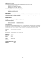
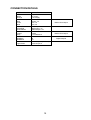
SUPER HALCYON 3 USER MANUAL Premier Way, Abbey Park Romsey, Hampshire, S051 9DH England Tel: (+44) 01794 518448 Fax: (+44) 01794 518077 Web: www.BandG.com © Brookes & Gatehouse Ltd. 1987 The copyright of this Manual is the property of Brookes & Gatehouse Ltd. CONTENTS Para Page DESCRIPTION.........................................................................................3 INTRODUCTION ..................................................................................3 COMPASS UNIT ..................................................................................3 COMPASS INDICATOR .......................................................................3 OPERATION ............................................................................................4 FAULT LOCATION..................................................................................5 ALL OUTPUTS DEFECTIVE ................................................................5 DIGITAL OUTPUTS..............................................................................5 INSTALLATION .......................................................................................6 MASTER COMPASS UNIT ..................................................................6 CONNECTIONS (SEE FIG. 1)................................................................7 CALIBRATION.........................................................................................8 AUTOMATIC CALIBRATION................................................................8 COMPASS CALIBRATION PROCEDURE ........................................................9 AUTOMATIC CALIBRATION INHIBIT ...........................................................10 TECHNICAL DATA................................................................................10 2 DESCRIPTION INTRODUCTION Halcyon is a high performance electronic transmitting compass (sometimes known as a fluxgate compass) designed for use on both sailing and power craft. It may be used as a compass in its own right, or it may be coupled directly to other B&G instruments such as the B&G Hercules System, satnavs, autopilots etc. The boat's heading may be displayed on an optional bulkhead mounting indicator unit by a pointer with a 360° scale showing cardinal points Up to three indicators may be fitted. The compass sensor and the indicators are fully watertight, corrosion proof and shock proof. The unit has been designed for use at sea and is tested rigorously. A digital readout is available when connected to the Hercules system. COMPASS UNIT One important feature of the Super Halcyon 3 is its ability to 'learn' the magnetic effect of the vessel on the compass and automatically apply deviation correction. By following the simple procedure detailed in Section 4 of this book. Compass errors can be reduced to an insignificant The fluxgate principle employed in the sensor does not rely on magnets or compass cards for its operation, and offers excellent performance in adverse conditions, with rapid recovery from turning errors. Traditional compass characteristics, such as -swirl', are completely eliminated. COMPASS INDICATOR This unit is a standard B&G four-inch indicator. The dial is marked with cardinal points numerals every 30 degrees, and five degree graduations. Internal scale illumination is provided. The indicator is in the form of an arrow, the head of which shows the ship's heading. 3 OPERATION The compass system is activated by switching on the power supply. The compass automatically compensates for changes in the strength of the earth's magnetic field after calibration. The Super Halcyon 3 works in both the northern and southern hemispheres without modification. (See section 5 on automatic calibration). All outputs are protected against accidental short circuit In the event of a short circuit, the compass will switch off. To return to normal operation, first remove the cause of the short circuit, switch off the power to the compass, wait a few seconds and then re-apply the power. The compass will then work normally. The heading may be seen on the analogue display (compass repeater) or in digital form through the Hercules system. 4 FAULT LOCATION ALL OUTPUTS DEFECTIVE Ensure that the ship's supply is connected to the compass. A voltage of between 10V and 30V should be present between pin 3 with the orange conductor (+ve) and pin 2 with the black conductor (—ve) of cable 135-0A-113 at the 18-way connector. Whilst operating correctly the Super Halcyon 3 emits a quiet high-pitched audible tone. All outputs are protected against accidental short circuit. In the event of a short circuit, the compass switches off automatically. To return to normal operation, first identify and rectify the short circuit, switch off the supply for a few seconds and then switch on the power again. If heading rotates in wrong direction, reverse any two phases. The compass will step from 0° to current heading at power on. If problems persist, the most practicable test is to substitute with known operational units until the defective unit is identified. Repairs and investigations within the compass are to be undertaken by an authorised B&G agent only. DIGITAL OUTPUTS For problems associated with the digital outputs, check that the compass has been configured to the output you require. The output configuration that is set at the factory is marked on a label on the compass case. Consult your dealer for details. (Also refer to Para 6.1). 5 INSTALLATION MASTER COMPASS UNIT The main consideration with installation lies in selecting a suitable mounting position -this may be above or below decks. To take maximum advantage of the remote compass sensor, the mounting position should be chosen with the following points in mind. (a) FIXED MACHINERY AND FITTINGS Keep as far as possible from fixed machinery containing iron or steel. Obvious examples are iron keels, anchors and chain, engines, auxiliary engines and generators, battery chargers, electric motors, refrigeration equipment, galley stoves conventional compasses and electronic instruments. Also, keep clear of ship's wiring where heavy current is carried (e.g. navigation light cables). As a general rule, the distance from a ferrous object should be greater than three times the largest dimension of that object Magnetic interference is strongly dependent on distance so even small extra clearances are worth achieving. As most significant fixed gear is generally aft, a forward location is usually suitable. Make sure that clamp fastenings are non-magnetic (b) MOVEABLE GEAR The effect of fixed gear is compensated by the automatic compass calibration, but that of moveable gear cannot. Avoid proximity to any locker where items containing iron or steel (e.g. tools, cameras, audio and video tapes, books with steel ring binders) are stored. Even food cans are significant. Especially avoid the normal storage positions of iron/steel objects (e.g. recovery magnets, outboard motors, audio/video playback units including television receivers and loudspeakers). Remember also that all types of stainless steel are magnetic to a greater or lesser extent e.g. fuel or water tanks. Note that in case of doubt a simple test is to bring the suspected item close to a compass (Halcyon or conventional) and note any deviation. All possible orientations should be tried. (c) SHIP'S MOTION Despite the relative immunity of the Halcyon to motion, it is advisable to avoid positions at the extremities of the vessel where motion is violent. (d) ACCESS Remember to leave reasonable access to the compass sensor to facilitate compass adjustment where necessary. (e) STEEL HULLED VESSELS Ships with a large steel content in the hull (including ferro-cement hulls) will normally be obliged to have the Halcyon sensor mounted above decks - a position on main or mizzen mast is satisfactorywhilst bearing in mind the requirements of (c) above. Normally 4-5 metres (12-16ft) above deck is adequate. 6 CONNECTIONS It should be noted that when Super Halcyon 3 is used with Hercules alone, power is derived directly from the Hercules Computer backplate. When the Super Halcyon 3 is used independently, the power supply should be connected to the ship's 12/24V dc supply via a 1A fuse. For connection details, refer to installation sheet. Once the mounting position has been chosen it is advisable to complete the wiring before securing the sensor unit in place. Proper operation can then be confirmed by switching on and rotating the sensor unit about a vertical axis. The variation in displayed heading will be clearly shown on either the repeater, or on the Hercules digital display (note that for easy reading the latter is heavily damped). Whilst operating, Halcyon 3 will emit a quiet high-pitched tone. When correct operation has been verified, the compass should be lined up fore-and-aft using the marks on the top. Once the initial calibration has been completed, the compass sensor may be rotated for exact alignment before final tightening of the clamp screws. Do not over tighten. It is recommended that the cable be firmly clamped near to the sensor unit as an aid to mechanical stability. Do not bend the cable to a curve of less than 100mm radius adjacent to the plug. 7 CALIBRATION The software in the compass allows the compass to 'learn' the magnetic fields in the vessel that are causing the deviation errors. By following the simple procedure below, deviation errors are reduced to an insignificant level. AUTOMATIC CALIBRATION Align the markings on the top of the compass approximately with the fore-and-aft line of the vessel by rotating the compass unit within its mounting bracket. The compass calculates the correction coefficients each time the boat completes a 540° (one and a half circles) turn, provided: (a) The 540° turn is completed without changing the direction of the turn. (b) The rate of change of heading does not exceed 3°/second during the 540° turn i.e. 540° must not be achieved in less than three minutes. (See 1 below). (c) The rate of change of heading does not fall below 0.2°/second during the 540° turn i.e. 540° must not be achieved in more than forty five (45) minutes. (See 1 below). (d) Automatic calibration has not been inhibited as described in paragraph 5.1.1 of this book. (e) The change in heading is constant. These criteria are chosen to ensure that normal sailing manoeuvres do not inadvertently initiate the calibration sequence. 8 Compass Calibration Procedure (1) At a speed of about three knots, and away from any large steel structures, slowly motor the boat through a full circle (360°) taking 6-10 minutes to complete circle. The calibration takes place during this time. Continue to turn to complete a further half circle (180°). It is helpful to have a watch with seconds running and a compass or repeater in front of the helmsman. To achieve a six-minute turn the ship's head should be passing through 10° every ten seconds. The turn should be at a constant rate. The compass will accept the calibration if there are small deviations from a constant turn, but sudden sharp turns will mean the calibration is discarded. (2) When the compass has completed the calibration, the displayed heading will rotate in the opposite direction for 360° and settle on the correct bearing to indicate that the calibration is complete. Keep the boat slowly turning until this happens. If the repeater does not reverse, the compass has discarded the calibration because the turn has not been carried out in the correct manner. The calibration should be started up again. (3) The compass is now adjusted for deviation. If during subsequent use it is found that the Super Halcyon 3 is showing a small constant error on all bearings relative to the ship's calibrated magnetic compass, the compass sensor requires fine adjustment. After deducing the error. Slacken the sensor clamp and rotate the sensor in its bracket in the opposite direction to the error (1° = 1mm rotation). Tighten the clamp after adjustment 9 Automatic Calibration Inhibit The manoeuvres involved in carrying out the automatic calibration are selected in order to make accidental re-calibration very unlikely. Even if this should occur, this represents no real inconvenience to the navigator, but where ship operating regulations demand it, the calibration may be inhibited by disconnecting the brown wire from the compass at the junction box , cutting it back and insulating it. This facility is only available with installations using a junction box. Manual Initiation of Calibration Should a calibration run be required with the junction box wiring modified as described in the Automatic Calibration Paragraph, prepare to make the run as for an Automatic Calibration, and then connect a wire between the brown and black terminals as indicated by the dotted line in the wiring diagram for ten seconds. The procedure described in the Automatic Calibration procedure can then be performed. TECHNICAL DATA The main output from the Super Halcyon 3 can be connected directly with the B&G Hercules system. It can also drive the analogue repeater compass directly. Three other outputs are available from the standard compass (386-00-009) to interface with a wide range of autopilots, radars, position fixers, computers etc. (a) A three-wire analogue output, 2.5 ref/sine/cosine. (b) A digital output which can be configured to N+1 format, or to 1/6° step Gray Code format (gyro). (c) An NMEA interface which can also be used with the RS232 port of a computer. For the latest information on interfacing, please contact your nearest B&G service agent. The Output configuration of your compass is indicated by a code on a label attached to the sensor unit. Standard Setting Output 3-Wire Sine/Cosine With Internal 2.5V Ref. With External 2.5V Ref. Digital Output: Stepper N+1 Open Collector 5V NMEA Sentence Output: $HCDM $HCHSC $HCVHW Damping: 0.3 – 99 Seconds I E S N C 5 0.3 10 Code M C W SPECIFICATION GENERAL The Super Halcyon 3 sensor unit and the analogue compass repeater are fully sealed for use in marine conditions. PERFORMANCE Sensor Accuracy (when properly adjusted): + 1° max. error at 0° heel + 2° max. error at 20° heel + 3° max. error at 30° heel Repeater Accuracy: +1.5° max. error Temperature Range: -10°C to +60°C Relative Humidity: 0 – 100% Earth’s field strength range (Horizontal component): 5 to 45 microTesla (equator to 80° latitude) Maximum number of indicators: 3 Maximum heading rate: 33°/second Response Time: minimum 0.25 seconds Calibration turn rate: Maximum 3°/second Minimum 0.2°/second 11 Electrical Characteristics of Outputs Repeater Output Differential sin/cos output (nominal dc output voltages with respect to ship’s supply negative): Heading Red Wire Green Wire Violet Wire Blue Wire Cos Cos + Sin Sin + 0° 1.5V 5.5V 3.5V 3.5V 90° 3.5V 3.5V 1.5V 5.5V 180° 5.5V 1.5V 3.5V 3.5V 270° 3.5V 3.5V 5.5V 1.5V Cosine Output Sine Output Note: The outputs are intended for direct drive of dc synchro resolver repeaters, and so have very low output impedance. 12 Sine Cosine Reference Output: Sine and Cosine output +1.1V @ 0.5mA Reference 2.5V internal* Heading Sine Cosine 0° +0.75V +0.75V 45° 0.0V +1.1V 90° -0.75V +0.75V 135° -1.1V 0.0V 180° -0.75V -0.75V 215° 0.0V -1.1V 270° +0.75V -0.75V 315° +1.1V 0.0V Voltages With Respect to 2.5V ref. *External reference is available. Please consult your dealer for details. Digital Output This is a stepper output using the 3-phase Gray code*. D1 D2 D3 open collector up to 50V or 5V @ 10mA External resistors may be required if open collector is used. *N+1 output is also available, 5V or open collector. Please consult your dealer if you require these outputs. N+1 output (a heading of 234° output gives 235 pulses): 5V pulse train on D3 1 second update rate (TTL compatible) 13 NMEA 0183 V1.5 Output The compass outputs the following NMEA standard sentence once per second: $HCHDM,xxx.x,M,*NN CR LF $HCHSC,xxx.x,T,XXX.X,M*NN CR LF $HCVHW,xxx.x,T,xxx,x,M,,,,*NN CR LF The following NMEA 0183 sentences may be input: $XXHVD,xxx.x,E*NN CR LF $XXHVM,xxx.x,E*NN CR LF RS232 Output While the electrical specification set out by the NMEA for the 0183 standard is not identical to the electrical specification of RS232, the similarity is such that the compass NMEA input/output lines will usually interface with a computer RS232 link. POWER SUPPLY Voltage: 10V – 30V dc, lighting for repeater: 12V Current Drain (typical): 55mA (No indicator) 95mA (1 indicator) 135mA (2 indicators) 175mA (3 indicators) Output Protection: All outputs are protected against accidental short circuit. In the event of a short circuit, the compass will switch off. To return to normal operation, first remove the short circuit, switch off the power to the compass, wait a few seconds and then re-apply the power. The compass will then work normally. Repeater: two winding synchro repeater SIZE Sensor Unit: Cylinder 120mm dia. x 100mm high Indicator: Bezel width: Barrel dia: Depth: 108mm 63mm 57mm Cable: 18 core 15m WEIGHT Compass Sensor Unit: 0.55kg Indicator: 0.6kg 14 CONNECTION DETAILS Wire Colour White Black Orange Green Red Violet Blue Yellow/Red White/Red Green/Brown Pink Yellow Grey Red/Brown Red/Blue Red/Black Brown Light Green Function Ship’s Earth 0V Supply +12V Supply Cosine +ve Cosine –ve Sine –ve Sine +ve NMEA Input +ve NMEA Input –ve NMEA Output +ve Sine Cosine 2.5V Reference D1 D2 D3 External Input 1 (Calibrate) External Input 2 15 B&G 4-Wire Output B&G 3-Wire Output Digital Outputs