1
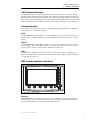
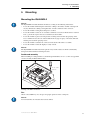
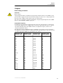
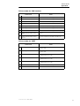
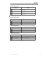
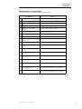
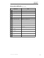
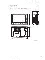
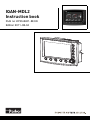
IQAN-MDL2
Instruction book
Publ no HY33-8401-IB/UK
Edition 2011-08-04
Contents
1
Introduction . . . . . . . . . . . . . . . . . . . . . . . . . . . . . . . . . . . . . . . . . . . . . . . . . . . . 1
Warnings . . . . . . . . . . . . . . . . . . . . . . . . . . . . . . . . . . . . . . . . . . . . . . . . . . . . 1
Overview of relevant documentation . . . . . . . . . . . . . . . . . . . . . . . . . . . . . . . 2
2
Precautions . . . . . . . . . . . . . . . . . . . . . . . . . . . . . . . . . . . . . . . . . . . . . . . . . . . . 3
Read This . . . . . . . . . . . . . . . . . . . . . . . . . . . . . . . . . . . . . . . . . . . . . . . . . . . . 3
Design of control system . . . . . . . . . . . . . . . . . . . . . . . . . . . . . . . . . . . . . 3
Start-up, maintenance, and diagnostics . . . . . . . . . . . . . . . . . . . . . . . . . 4
3
Product description . . . . . . . . . . . . . . . . . . . . . . . . . . . . . . . . . . . . . . . . . . . . . 5
IQAN-MDL2 . . . . . . . . . . . . . . . . . . . . . . . . . . . . . . . . . . . . . . . . . . . . . . . . . . 5
System overview . . . . . . . . . . . . . . . . . . . . . . . . . . . . . . . . . . . . . . . . . . . . . . 5
I/O . . . . . . . . . . . . . . . . . . . . . . . . . . . . . . . . . . . . . . . . . . . . . . . . . . . . . . . . . 6
Voltage inputs . . . . . . . . . . . . . . . . . . . . . . . . . . . . . . . . . . . . . . . . . . . . . 6
Digital inputs . . . . . . . . . . . . . . . . . . . . . . . . . . . . . . . . . . . . . . . . . . . . . . 6
Frequency inputs . . . . . . . . . . . . . . . . . . . . . . . . . . . . . . . . . . . . . . . . . . 6
Proportional outputs . . . . . . . . . . . . . . . . . . . . . . . . . . . . . . . . . . . . . . . . 7
High power On/Off outputs . . . . . . . . . . . . . . . . . . . . . . . . . . . . . . . . . . . 7
CAN related functions . . . . . . . . . . . . . . . . . . . . . . . . . . . . . . . . . . . . . . . . . . 8
Communication . . . . . . . . . . . . . . . . . . . . . . . . . . . . . . . . . . . . . . . . . . . . . . . 8
CAN . . . . . . . . . . . . . . . . . . . . . . . . . . . . . . . . . . . . . . . . . . . . . . . . . . . . 8
RS232 . . . . . . . . . . . . . . . . . . . . . . . . . . . . . . . . . . . . . . . . . . . . . . . . . . . 8
USB . . . . . . . . . . . . . . . . . . . . . . . . . . . . . . . . . . . . . . . . . . . . . . . . . . . . . 8
HMI (human machine interface) . . . . . . . . . . . . . . . . . . . . . . . . . . . . . . . . . . . 8
Features . . . . . . . . . . . . . . . . . . . . . . . . . . . . . . . . . . . . . . . . . . . . . . . . . 8
Encoder . . . . . . . . . . . . . . . . . . . . . . . . . . . . . . . . . . . . . . . . . . . . . . . . . . 9
Buttons . . . . . . . . . . . . . . . . . . . . . . . . . . . . . . . . . . . . . . . . . . . . . . . . . . 9
Display . . . . . . . . . . . . . . . . . . . . . . . . . . . . . . . . . . . . . . . . . . . . . . . . . . 9
Fan . . . . . . . . . . . . . . . . . . . . . . . . . . . . . . . . . . . . . . . . . . . . . . . . . . . . . . . . 10
Memory for logging . . . . . . . . . . . . . . . . . . . . . . . . . . . . . . . . . . . . . . . . . . . 10
4
Safety . . . . . . . . . . . . . . . . . . . . . . . . . . . . . . . . . . . . . . . . . . . . . . . . . . . . . . . . 11
Internal diagnostics . . . . . . . . . . . . . . . . . . . . . . . . . . . . . . . . . . . . . . . . . . . 11
CAN-bus interruption . . . . . . . . . . . . . . . . . . . . . . . . . . . . . . . . . . . . . . . . . . 11
Current check . . . . . . . . . . . . . . . . . . . . . . . . . . . . . . . . . . . . . . . . . . . . . . . . 11
Emergency stop . . . . . . . . . . . . . . . . . . . . . . . . . . . . . . . . . . . . . . . . . . . . . . 11
5
Mounting . . . . . . . . . . . . . . . . . . . . . . . . . . . . . . . . . . . . . . . . . . . . . . . . . . . . . 12
Mounting the IQAN-MDL2 . . . . . . . . . . . . . . . . . . . . . . . . . . . . . . . . . . . . . . 12
Dashboard assembly . . . . . . . . . . . . . . . . . . . . . . . . . . . . . . . . . . . . . . 12
Fan . . . . . . . . . . . . . . . . . . . . . . . . . . . . . . . . . . . . . . . . . . . . . . . . . . . . 12
6
Installation . . . . . . . . . . . . . . . . . . . . . . . . . . . . . . . . . . . . . . . . . . . . . . . . . . . . 13
Connector C1 . . . . . . . . . . . . . . . . . . . . . . . . . . . . . . . . . . . . . . . . . . . . . . . . 13
Connector pin assignments . . . . . . . . . . . . . . . . . . . . . . . . . . . . . . . . . . . . . 14
Supply voltage . . . . . . . . . . . . . . . . . . . . . . . . . . . . . . . . . . . . . . . . . . . . . . . 16
Emergency stop . . . . . . . . . . . . . . . . . . . . . . . . . . . . . . . . . . . . . . . . . . 16
Connecting of Supply Voltage . . . . . . . . . . . . . . . . . . . . . . . . . . . . . . . . 16
Polarity reversal . . . . . . . . . . . . . . . . . . . . . . . . . . . . . . . . . . . . . . . . . . 16
Reference voltage, VREF . . . . . . . . . . . . . . . . . . . . . . . . . . . . . . . . . . . 17
Diagnostic interfaces . . . . . . . . . . . . . . . . . . . . . . . . . . . . . . . . . . . . . . . . . . 18
CAN diagnostics connection . . . . . . . . . . . . . . . . . . . . . . . . . . . . . . . . . 18
RS232 connection C2 . . . . . . . . . . . . . . . . . . . . . . . . . . . . . . . . . . . . . . 18
USB connection C2 . . . . . . . . . . . . . . . . . . . . . . . . . . . . . . . . . . . . . . . . 18
USB and "ground loops" (differences in ground potential) . . . . . . . . . . 19
Instruction book, IQAN-MDL2
ii
Contents
RS232 modem connection, C1 . . . . . . . . . . . . . . . . . . . . . . . . . . . . . . . 19
Voltage inputs . . . . . . . . . . . . . . . . . . . . . . . . . . . . . . . . . . . . . . . . . . . . . . . 20
Connecting sensors to the voltage inputs . . . . . . . . . . . . . . . . . . . . . . . 20
Connecting potentiometers to the voltage inputs . . . . . . . . . . . . . . . . . 20
Connecting switches to the voltage inputs . . . . . . . . . . . . . . . . . . . . . . 21
Digital inputs . . . . . . . . . . . . . . . . . . . . . . . . . . . . . . . . . . . . . . . . . . . . . . . . . 22
Connecting switches to the digital inputs . . . . . . . . . . . . . . . . . . . . . . . 22
Frequency / directional inputs . . . . . . . . . . . . . . . . . . . . . . . . . . . . . . . . . . . 24
Connecting sensors to the frequency inputs . . . . . . . . . . . . . . . . . . . . . 24
Connecting sensors to the directional inputs . . . . . . . . . . . . . . . . . . . . 24
Outputs . . . . . . . . . . . . . . . . . . . . . . . . . . . . . . . . . . . . . . . . . . . . . . . . . . . . . 26
Back-ending of module . . . . . . . . . . . . . . . . . . . . . . . . . . . . . . . . . . . . . 26
Connecting proportional valves and devices . . . . . . . . . . . . . . . . . . . . . 27
Connecting loads to proportional outputs . . . . . . . . . . . . . . . . . . . . . . . 27
Connecting control relays and on/off valves . . . . . . . . . . . . . . . . . . . . . 27
7
Start-up . . . . . . . . . . . . . . . . . . . . . . . . . . . . . . . . . . . . . . . . . . . . . . . . . . . . . . . 29
Start-up procedures . . . . . . . . . . . . . . . . . . . . . . . . . . . . . . . . . . . . . . . . . . . 29
Starting the control system . . . . . . . . . . . . . . . . . . . . . . . . . . . . . . . . . . 29
Prepare for system start . . . . . . . . . . . . . . . . . . . . . . . . . . . . . . . . . . . . 29
Start the system . . . . . . . . . . . . . . . . . . . . . . . . . . . . . . . . . . . . . . . . . . 29
8
System Diagnostics . . . . . . . . . . . . . . . . . . . . . . . . . . . . . . . . . . . . . . . . . . . . 30
Diagnostic pages . . . . . . . . . . . . . . . . . . . . . . . . . . . . . . . . . . . . . . . . . . . . . 30
Safe mode . . . . . . . . . . . . . . . . . . . . . . . . . . . . . . . . . . . . . . . . . . . . . . . . . . 30
Appendix A . . . . . . . . . . . . . . . . . . . . . . . . . . . . . . . . . . . . . . . . . . . . . . . . . . . 31
IQAN-MDL2 Technical Overview . . . . . . . . . . . . . . . . . . . . . . . . . . . . . . . . . 31
Absolute Maximum Ratings . . . . . . . . . . . . . . . . . . . . . . . . . . . . . . . . . 31
Environmental ratings . . . . . . . . . . . . . . . . . . . . . . . . . . . . . . . . . . . . . . 31
Recommended Operating Conditions . . . . . . . . . . . . . . . . . . . . . . . . . . 32
System . . . . . . . . . . . . . . . . . . . . . . . . . . . . . . . . . . . . . . . . . . . . . . . . . 32
. . . . . . . . . . . . . . . . . . . . . . . . . . . . . . . . . . . . . . . . . . . . . . . . . . . . . . . 33
Appendix B . . . . . . . . . . . . . . . . . . . . . . . . . . . . . . . . . . . . . . . . . . . . . . . . . . . 36
Error messages and actions . . . . . . . . . . . . . . . . . . . . . . . . . . . . . . . . . . . . 36
Failure Modes . . . . . . . . . . . . . . . . . . . . . . . . . . . . . . . . . . . . . . . . . . . . . . . 36
Failure modes for FAN . . . . . . . . . . . . . . . . . . . . . . . . . . . . . . . . . . . . . 36
Failure modes for CAN interface . . . . . . . . . . . . . . . . . . . . . . . . . . . . . . 37
Failure modes for VREF . . . . . . . . . . . . . . . . . . . . . . . . . . . . . . . . . . . . 37
Failure modes for VIN . . . . . . . . . . . . . . . . . . . . . . . . . . . . . . . . . . . . . . 38
Failure modes for DIN . . . . . . . . . . . . . . . . . . . . . . . . . . . . . . . . . . . . . . 38
Failure modes for FIN . . . . . . . . . . . . . . . . . . . . . . . . . . . . . . . . . . . . . . 38
Failure modes for DFIN . . . . . . . . . . . . . . . . . . . . . . . . . . . . . . . . . . . . . 38
Failure modes in Current Mode . . . . . . . . . . . . . . . . . . . . . . . . . . . . . . . 39
Failure modes in PWM mode . . . . . . . . . . . . . . . . . . . . . . . . . . . . . . . . 40
Appendix C . . . . . . . . . . . . . . . . . . . . . . . . . . . . . . . . . . . . . . . . . . . . . . . . . . . 41
Dimensioning of the IQAN-MDL2 module . . . . . . . . . . . . . . . . . . . . . . . . . . 41
Instruction book, IQAN-MDL2
iii
Warnings
1
1
Introduction
Introduction
These instructions are to be used as a reference tool for the vehicle manufacturer’s design, production, and service personnel.
The user of these instructions should have basic knowledge in the handling of electronic equipment.
Warnings
Sections marked with a symbol in the left margin, must be read and understood by everyone
using the system, carrying out service work, or making changes to hardware and software.
The different symbols used in this manual are defined below.
W ARNING
Sections labeled WARNING with a caution symbol in the left margin, indicate that a hazardous
situation exists. We use warnings, marked with the warning symbol, in two ways.
•
As a strong recommendation about work practices when using the product in the machine
(e.g. routines when updating an application). This use is common to the term 'hazardous situation', that a person is exposed to a hazard.
•
As a way of pointing out important information for the machine designer that in some way
relates to safety. This includes the design of the physical machine, and also the application
program being developed for the control system.
Not all document sections that contain information about safety are marked with a warning
symbol (there would be warnings everywhere). Failure to comply with the recommendations
can cause unintentional, and unexpected behavior of the control system. This can potentially
cause death, serious injury or property damage.
N OTICE
Sections labeled NOTICE with a notice symbol in the left margin, indicate there is important
information about the product. Ignoring this could result in less than optimal performance, or
damage to the product.
Contact the manufacturer if there is anything you are not sure about or if you have any questions
regarding the product and its handling or maintenance.
The term "manufacturer" refers to Parker Hannifin Corporation.
Instruction book, IQAN-MDL2
1
Overview of relevant documentation
1
Introduction
Overview of relevant documentation
The following publications are relevant for users of this product.
The main documentation contains information that is not found elsewhere.
The additional documentation contains product information in a compact format, for details on
the information found in those documents, consult this manual.
Main
Documentation
Compact
Documentation
IQANdesign
User Manual
IQAN-MDL2 Instruction Book
HY33-8401-IB
(this book)
IQAN-MDL2
Catalogue Datasheet
HY33-8401
IQAN-MDL2
Installation Sheet
HY33-8401-IS
IQAN-MDL2
Electrical Schematic
HY33-8401-ES
The IQAN-MDL2 module documentation system.
Instruction book, IQAN-MDL2
2
Read This
2
2
Precautions
Precautions
Work on the hydraulics control electronics may only be carried out by trained personnel who are
well-acquainted with the control system, the machine and its safety regulations.
W ARNING
Make sure that you have sufficient knowledge before designing, modifiying or servicing the
control system.
Read the relevant sections of this document before conducting any work on the control system.
W ARNING
This product is not field repairable.
N OTICE
As much as possible of the welding work on the chassis should be done before the installation of
the system. If welding has to be done afterwards, the electrical connections on the system must
be disconnected from other equipment. The negative cable must always be disconnected from
the battery before disconnecting the positive cable. The ground wire of the welder shall be positioned as close as possible to the place of the welding. The cables on the welding unit shall
never be placed near the electrical wires of the control system.
Read This
Design of control system
W ARNING
Risk of injury may be introduced by design of control system!
This product is designed to control hydraulic outputs. The control application must be designed
using basic safety principles so that unintentional movement is avoided.
The machine must be equipped with an emergency stop that stops all movement. Please refer to
section Emergency stop, on page 11.
Before you start
Read this document, as a minimum sections 1-7
Read the IQANdesign software user manual section on 'application safety'.
Instruction book, IQAN-MDL2
3
Read This
2
Precautions
Start-up, maintenance, and diagnostics
For all personnel carrying out installation, commissioning, maintenance or troubleshooting.
W ARNING
Work on the hydraulics control electronics may only be carried out by trained personnel who are
well-acquainted with the control system, the machine and its safety regulations.
Before you start,
Read section Start-up, on page 29.
Additional information for service
Mounting and maintenance instruction book.
Additional information for diagnosing the system
Read section System Diagnostics, on page 30, and see Appendix B, on page 36, in this document.
Use the IQANrun software user manual as a reference.
Instruction book, IQAN-MDL2
4
IQAN-MDL2
3
3
Product description
Product description
IQAN-MDL2
The IQAN-MDL2 is a combined display and bus master capable of running applications created
by IQANdesign software. Built on a 32-bit platform the unit has large computational power and
is capable of controlling complex applications.
The IQAN-MDL2 module.
System overview
A typical MDL2 system.
The master module, IQAN-MDL2, is the central unit in an IQANsystem. IQAN-MDL2 is a
driver information unit and a bus master that is intended for the high-end range of mobile
hydraulic applications. The IQAN system is a CAN (Controller Area Network) bus control system for total vehicle control (e.g. engine, transmission, working hydraulics, supervision). In
most applications the MDL2 display can replace all mechanical dial-type instruments.
The display in the module has very high optical performance across a wide operating temperature range and over a wide range of ambient light.
IQAN-MDL2 has three main roles in a vehicle’s control system; master control unit, information display and data gateway to other systems.
The MDL2 has four CAN interfaces that support ICP (IQAN CAN Protocol) for IQAN bus
communication. The buses may also be configured for SAE J1939 or Generic user defined protocols (e.g. CANopen). Additionally, any of the CAN buses may be used for diagnostic purposes. The unit has two diagnostic communication ports: RS232 and USB. An additional RS232
connection in the main connector is dedicated for external modems.
The IQAN-MDL2 also has multiple inputs and outputs that are designed to be flexibly configured using IQAN software for measurement and control.
All I/O are EMI filtered and protected against short circuit to -BAT and +BAT.
Instruction book, IQAN-MDL2
5
I/O
3
Product description
I/O
+BAT
CAN-H
-BAT
CAN-L
+RTC
CAN-H
CAN-L
+VREF
-VREF
MDL2
CAN-H
CAN-L
CAN-H
RS232-DATA IN
CAN-L
RS232-DATA OUT
PORT 0
PORT 2
PORT 1
PORT 3
DIAGNOSTIC
Voltage inputs
The IQAN-MDL2 module has eight (8) voltage inputs VIN-A thru VIN-H for connection of 0-5
Vdc signals. These inputs can be configured as digital inputs for reading switches. Voltage
inputs and digital inputs share positions, see below.
(8) Voltage inputs VIN-A, VIN-B, VIN-C, VIN-D.....VIN-H
or
(8) digital inputs DIN-E, DIN-F, DIN-G, DIN,H...... DIN-L
Digital inputs
The MDL2 module has four (4) digital inputs DIN-A thru DIN-D. DIN-B and DIN-C are multipurpose and can be configured in other ways.
Frequency inputs
Frequency
The input pin DIN-B may be configured as a frequency input.
Instruction book, IQAN-MDL2
6
I/O
3
Product description
Directional frequency
The input pins DIN-B and DIN-C may be configured as a directional frequency input for either
a quadrature input or directional input. Quadrature signals consist of two 90 degree square
waves and are phase-dependent. Directional inputs have one square wave for the frequency plus
a signal that is high or low to show direction and are considered level dependent.
Quadrature and directional inputs can operate in 2 modes. Speed which is frequency with direction and position which is a pulse count with direction.
Digital inputs, frequency input and directional frequency input share positions, see below.
(4) Digital inputs DIN-A, DIN-B, DIN-C, DIN-D
or
(3) digital inputs DIN-A, DIN-C, DIN-D and frequency input FIN-A
or
(2) digital inputs DIN-A, DIN-D and quadrature input DFIN-A+, DFIN-A-
Proportional outputs
The MDL2 module has two (2) double proportional outputs for controlling proportional valves.
These outputs can control two bi-directional valve sections or two single solenoid devices (ie.
proportional cartridge valves). The proportional outputs can be used in different modes.
Current mode
Current mode (current closed loop) proportional signals can be selected and the parameters configured using IQAN software. As a current output the specified frequency mA signal is sent to
the valve solenoid. The return line is monitored and the signal is modified by the controller to
maintain the commanded output as the solenoid coil heats up etc.
PWM mode
PWM mode (voltage open loop) proportional signals can be selected and the parameters configured using IQAN software. As a PWM output the specified frequency MR% duty cycle signal is
sent to the valve solenoid. The return line is not monitored. This type of output is intended for
Pulsar® type valves
For flexibility the proportional outputs may also be configured as up to two (2) on/off outputs
and up to four (4) on/off intputs. The proportional outputs, on-off outputs and on-off inputs share
positions, see below.
(2) double proportional outputs COUT-A, COUT-B (PWMOUT-A, PWMOUT-B)
or
(2) on/off outputs DOUT-G, DOUT-H. Configuring as DOUT’s allows the CRET pins to be used
as on/off inputs, (4) total, DIN-M thru DIN-P.
In order to increase the performance of proportional outputs when controlling proportional
valves, the dither frequency can be adjusted.
High power On/Off outputs
The IQAN-MDL2 module has six (6) on/off outputs that are high-side power outputs. These
outputs may not be configured as proportional, see below.
(6) On/off outputs DOUT-A thru DOUT-F
Instruction book, IQAN-MDL2
7
CAN related functions
3
Product description
CAN related functions
The IQAN-MDL2 uses a CAN-bus (CAN = Controller Area Network) to communicate with
IQAN expansion modules and other systems. The CAN-bus is a robust communication protocol
that is widely used and well proven within the automotive industry. The unit has four (4) CAN
buses, CAN-A thru CAN-D. The buses may be configured using IQAN software to be ICP (ICP
= IQAN CAN Protocol), SAE J1939 or Generic user defined CAN protocol (e.g. CANopen).
Communication
The communication interfaces are used for uploading/downloading applications or diagnostics
and typically are connected to a computer.
CAN
The IQAN-MDL2 has 4 CAN buses. Any of the CAN buses may be used for communication
and diagnostics. A CAN communication card is required to be installed in your PC to use this
feature.
RS232
The IQAN-MDL2 has two(2) RS232 interfaces. One is in the 42 pin main connector C1 and is
used to interface with external RS232 inputs (i.e. modems). The other is in the C2 connector, a
separate 10 pin connector, and is used for communicating with a PC.
USB
The MDL2 has a USB (device only) connection on connector C2. USB is a complement to
RS232 for high speed PC communication and diagnostics, for maximum voltage on USB pins,
see Appendix A, on page 31.
HMI (human machine interface)
A
B
C
D
=
F1
F2
F3
F4
F5
The IQAN-MDL2 front panel HMI.
Features
IQAN-MDL2 has a 6.5" transflective screen for easy readability in a wide range of ambient
light conditions. There are eleven buttons and a rotary encoder knob for input and menu selection. The functionality of the different contols are listed below
Instruction book, IQAN-MDL2
8
HMI (human machine interface)
3
Product description
Encoder
The encoder is of the Jog shuttle type (rotary knob with pushbutton). Pushing the knob equals
’enter’. The knob can be programmed so that its pushbutton feature can act as a virtual input
button and perform some function depending on the current display page. Rotating the shuttle
knob can be programmed to adjust values, select from items in a table or cycle thru display
pages.
Buttons
The buttons are arranged on the bottom and right hand side of the display.
•
F1 thru F5 function buttons.
Programmable ’softkeys’ that may be configured by the user to bring up a display page,
bring up an adjustment group or act as a virtual input.
•
A thru D function buttons.
Programmable ’softkeys’ that may be configured by the user to bring up a display page,
bring up an adjustment group or act as a virtual input.
•
Menu button (three horizontal lines).
Always brings up the Menu page. It is not programmable.
•
’Esc’ or BACK button (left arrow).
Returns you to the previous display page. May be configured by the user to bring up a display page or act as a virtual input.
Display
Brightness
The brightness is easily adjusted by pressing the ’menu’ button and following the prompts to the
backlight settings section.
Burn-in
The MDL’s TFT display, like other computer viewing screens can have a ghost picture occur if
a static image is left on the display for extended periods of time. For the best viewing over the
life of the product we recommend using the screensaver functionality to prevent the burn-in of a
display page image.
N OTICE
To avoid burn-in, use the screensaver on the display.
Maintenance
The 6.5" transflective display is a high quality viewing interface and reasonable care should be
taken to maintain it.
The display can be cleaned with an LCD cleaning solution found in many stores. Use a lightly
dampened lint-free, non-abrasive cloth when cleaning the display.
N OTICE
To avoid scratches, do not wipe or clean a dry display.
Appearance
Please refer to the IQANdesign software manual for display programming information.
Instruction book, IQAN-MDL2
9
Fan
3
Product description
Fan
The unit has a cooling fan and heatsink to remove heat from inside the enclosure.
Maintenance
First clean the metal fins and fan housing with a brush to remove loose dirt and dust. Avoid
pushing debris into the fan.
After that, we recommend that you clean in between the curved metal fin section and fan housing with a small brush or cotton swab to remove trapped dirt.
N OTICE
Do not use compressed air to blast dirt off of the fan and heatsink. You may cause damage to the
fan!
Memory for logging
The unit has an internal memory dedicated for logging events. Memory logging is stored in
16Mbyte data flash with a power-fail-safe file system.
Instruction book, IQAN-MDL2
10
Internal diagnostics
4
4
Safety
Safety
Internal diagnostics
The module performs a number of self-checks that improve safety. Checks include monitoring
of voltage supplies, checksums on memory and a watchdog that monitors software execution.
The module is using a real time operating system which supervises software execution.
If a critical error is detected, the module is stopped, with CAN bus and outputs off.
CAN-bus interruption
The IQAN-MDL2 communicates with expansion modules on the CAN-bus. Both the master
and the modules check for any interruptions in CAN-bus communication. If an error occurs the
master will use zero or an application defined error value for the module inputs, and the module
outputs will be off.
The error will be presented with a related message on the IQAN-MDL2 display.
Current check
For the proportional outputs when used in current mode, a current check is performed. If an
error is detected, this will be indicated on the master module display, and the output will shut
off.
The module can detect open-circuit, short-circuit to +BAT/-BAT or short-circuit to other proportional output and return pins.
Emergency stop
W ARNING
Risk of injury! The emergency stop must disconnect the power supply to the module; do not
connect the emergency stop as a signal input only.
The emergency stop must be installed so that the risk of reverse feed of the module is avoided,
see section Emergency stop, on page 16.
Instruction book, IQAN-MDL2
11
Mounting the IQAN-MDL2
5
5
Mounting
Mounting
Mounting the IQAN-MDL2
N OTICE
The IQAN-MDL2 module should be mounted according to the following instructions:
•
Locate the module eliminating the risk for the cabling to be folded, crushed or damaged in
any way. Ensure the cabling cannot pull, twist or induce sideload on the connector.
•
Locate the module so that physical impact is avoided.
•
Locate the module so that air can circulate to eliminate excess heat. Ensure that no external
heat, e.g. from the engine or heater, is transferred to the module.
•
Locate the module to protect it from pressure washing and water directly spraying on the
face or similar. Protect the rear of the module from any type of spray or moisture. The unit
must be protected from spraying water!
•
Locate the module so that the PC connector in the back of the unit is accessible.
•
Locate the module so that the display is easily viewed.
N OTICE
The IQAN-MDL2 module must not be placed in any marine related or similar continuously
damp environment without external protection.
Dashboard assembly
When installing in a dash panel the recommended panel thickness is 1.0 - 3.5 mm. Use type PT4
screws to mount (included with bracket).
Mv = 0.8 - 1.0 Nm
PT40 screw
200
0
13
Mounting of the MDL2 with bracket.
Fan
Allow at least 100mm (3.94") airspace for proper operation of the cooling fan.
N OTICE
Do not install into an enclosure that restricts airflow.
Instruction book, IQAN-MDL2
12
Connector C1
6
6
Installation
Installation
Connector C1
42
29
28
15
14
1
Connector kit
Parker no. 5031063
Housing
Amp no. 1-963226-1
Casing
Amp no. 0-965643-1
Pin types*
Amp no. 963711-2 (MT)
Amp no. 929938-1 (JPT)
Cables
0,75-1,0 mm² (MT)
1,5-2,5 mm² (JPT)
Seals
Amp no. 963530-1 (MT)
Amp no. 828905-1 (JPT)
Plugs (for empty pos.)
Amp no. 963531-1 (MT)
Amp no. 828922 (JPT)
IQAN crimping tool
references
Blue handle, pos. A
use blue extraction tool
Red handle, pos. B
use yellow extraction tool
IQAN tool kit
Parker no. 5031061
+BAT
CAN-H
-BAT
CAN-L
+RTC
CAN-H
*= The connector contains two types of
terminals; MT (Micro Timer) and JPT
(Junior Power Timer).
CAN-L
+VREF
-VREF
MDL2
CAN-H
CAN-L
CAN-H
RS232-DATA IN
CAN-L
RS232-DATA OUT
PORT 0
PORT 2
PORT 1
PORT 3
DIAGNOSTIC
Instruction book, IQAN-MDL2
13
Connector pin assignments
6
Installation
Connector pin assignments
Logical
Symbol
Pin
No.
(I)nput or
(O)utput
Function description
and/or Signal name(s)
+BAT
28
-
Power supply, positive.
-BAT
15
-
Power supply, negative ground
+RTC
42
-
Power supply for Real Time Clock, positive
+VREF
14
-
Voltage reference for external sensors. Sourcing +5V.
-VREF
1
-
Voltage reference for external sensors. Return (0V).
CAN-A-H
CAN-B-H
CAN-C-H
CAN-D-H
2
4
6
8
-
CAN high voltage bus line, will be HIGH in dominant state.
CAN-A-L
CAN-B-L
CAN-C-L
CAN-D-L
3
5
7
9
-
CAN low voltage bus line, will be LOW in dominant state.
RS232-TD
30
-
RS232 data out
RS232-RD
31
-
RS232 data in
P0 is an 8 pin input port with alternate functions on four inputs.
P0
P0.0
P0.1
P0.2
P0.3
P0.4
P0.5
P0.6
P0.7
18
19
20
21
32
33
34
35
I
I
I
I
I
I
I
I
P1 is a 4 pin input port with alternate functions on two inputs.
P1
P1.0
P1.1
P1.2
P1.3
22
23
36
37
I
I
I
I
DIN
DIN-A
DIN-B
DIN-C
DIN-D
FIN
FIN-A
-
DFIN
DFIN-A+
DFIN-A-
P2 is an 6 pin output port.
P2
P2.0
P2.1
P2.2
P2.3
P2.4
P2.5
VIN
DIN
VIN-A
DIN-E
VIN-B
DIN-F
VIN-C
DIN-G
VIN-D
DIN-H
VIN-E
DIN-I
VIN-F
DIN-J
VIN-G
DIN-K
VIN-H
DIN-L
Note: DIN-E to DIN-L have high impedance inputs (62K Ohm).
13
27
41
12
26
40
Instruction book, IQAN-MDL2
O
O
O
O
O
O
DOUT
DOUT-A
DOUT-B
DOUT-C
DOUT-D
DOUT-E
DOUT-F
14
Connector pin assignments
6
Logical
Symbol
Pin
No.
(I)nput or
(O)utput
Installation
Function description
and/or Signal name(s)
P3 is a 6 pin input/output port with alternative functions.
P3
COUT
PWMOUT
DIN/DOUT
PWMOUT-A
PWMRET-A+
PWMRET-A-
DOUT-G
DIN-M
DIN-N
P3.0
P3.1
P3.2
11
25
39
O
O/I
O/I
COUT-A
CRET-A+
CRET-A-
P3.3
P3.4
P3.5
10
24
38
O
O/I
O/I
COUT-B
PWMOUT-B
DOUT-H
CRET-B+
PWMRET-B+
DIN-O
CRET-BPWMRET-BDIN-P
Notes:
If a COUT block (COUT-x, CRET-x+, CRET-x-) is used, all three pins
are configured as COUT.
If a PWMOUT block (PWMOUT-x, PWMRET-x+, PWMRET-x-) is
used, all three pins are configured as PWMOUT.
If a DIN-x or DOUT-x is used in a block (COUT-x, CRET-x+, CRET-x-),
all three pins are configured as corresponding DIN-x and DOUT-X.
DIN-I to DIN-T are equipped with clamping diode, risk for backending.
Shaded positions are Junior Power Timer pins. Unshaded positions are Micro Timer pins. See section Connector C1, on page 13 for
wire, seal, pin number and crimping tool information. The IQAN tool kit is found in the ’IQAN accessories’ datasheet.
Instruction book, IQAN-MDL2
15
Supply voltage
6
Installation
Supply voltage
W ARNING
Before any installation of the IQAN system can take place, make sure the ignition lock is turned
off and the battery is disconnected.
Emergency stop
Make sure an Emergency Stop disconnecting the power supply, is easily accessible at any time.
The figure below shows how to connect the emergency stop.
Connecting of Supply Voltage
The supply voltage, should be within the operating range, see Appendix A, on page 31. Connect
the supply voltage to +BAT, position 28 and -BAT, position 15. Protect the module by using a
fuse. Requisite fuse level should be 20 A, fast (F).
RTC supply
The real time clock, +RTC, requires a separate positive power connection. Connect the supply
voltage to +RTC, position 42 through a 1.5K ohm resistor. The resistor should be as close
to the battery as possible for safety.
W ARNING
Risk of injury!
To reduce the risk for uncontrolled supply of the IQAN-MDL2, i.e a short circuit between the
+RTC cable and +BAT, a resistor must be connected between the battery and the +RTC input.
This is important as this line is not controlled by an emergency stop.
The resistor should be placed close to the battery, as the “protected” part, is the cable between
the resistor and the unit.
This will prevent the +RTC wire from powering up the unit if shorted to +BAT. The same possibility exists from a short to CRET wires when they are used as digital inputs; refer to section
DIN-M to DIN-P, on page 22.
IQAN-MDL2
1.5K
+RTC, pos. 42
Emergency Stop
20 A
*
+BAT, pos. 28
-BAT, pos.15
+
-
* Symbol for disconecting switch for
battery, ignition lock and other fuses.
Connecting the emergency stop and voltage supply.
N OTICE
Do not use the chassis as the negative terminal.
Polarity reversal
The IQAN-MDL2 module is protected against power supply polarity reversal, provided an
external fuse, max 20 A (Fast) is being used.
If this fuse is not used, polarity reversal can damage the unit.
Instruction book, IQAN-MDL2
16
Supply voltage
6
Installation
Reference voltage, VREF
The IQAN-MDL2 module is internally equipped with a voltage regulator to generate the reference voltage VREF. The standard reference voltage will feed different kinds of sensors, potentiometers and joysticks.
IQAN-MDL2
+VREF, pos 14
-VREF, pos 1
VREF positions.
N OTICE
Maximum load for the VREF is different according to 12/24 Vdc power
supply, see Appendix A, on page 31.
Instruction book, IQAN-MDL2
17
Diagnostic interfaces
6
Installation
Diagnostic interfaces
IQAN software includes many tools for tuning, measuring, accessing logs and otherwise checking the performance or troubleshooting your control system. To use the diagnostic tools with the
IQAN-MDL2 you may choose between different ways to connect to the unit.
C2
C1
C1 and C2 connector locations.
CAN diagnostics connection
One of the four CAN buses of the IQAN-MDL2 may be dedicated for diagnostics.
Reserving a bus for diagnostics ensures that signals are not interrupted by other bus traffic. A
high-speed CAN interface is needed to use this feature. Contact Parker for information about
supported CAN interfaces.
A termination resistor is usually required at the CAN interface on the PC. Parker part number
5030182 or an equivalent 120 ohm resistor may be used. A flying lead cable may be connected
to the IQAN-MDL2 to provide a connector interface. The connection from IQAN-MDL2 to
diagnostic CAN interface can then be made quite easily. It is recommended that the connector
be a sealed, automotive type. When not being used this connector should be protected from the
environment with a cover or mating blank plug.
The recommended wiring to the IQAN-MDL2 connector C1 is shown below.
IQAN-MDL2
CAN-D-L, pos. 9
customer
provided
connector
120 ohm
CAN-D-H, pos. 8
Connecting for CAN bus diagnostics.
RS232 connection C2
For uploading, downloading and other communication with your computer, connector
C2 and 10 position cable 5030103 may be used for serial communication. The C2 connector
should not be used for permanent mounting to a computer.
USB connection C2
For uploading, downloading and other communication with your computer, connector
C2 and 10 position cable 5030110 may be used for USB communication. The C2 connector
should not be used for permanent mounting to a computer.
Instruction book, IQAN-MDL2
18
Diagnostic interfaces
6
Installation
USB and "ground loops" (differences in ground potential)
When systems consisting of machines, modules, computers and other devices with different
ground potentials are connected by a USB cable, a ground loop may be created. The grounds
may only differ by a few millivolts, or by much more. This can be significant when compared to
the low level voltage signals that are used in USB data transmission.
N OTICE
Protect the PC and unit from damage due to ground loops and surges!
Ground loops can cause problems in communicating and in extreme cases the amount of current
flow can damage the USB transceiver in the PC or the module.
A recommended way to prevent ground loops is to ensure that your system includes USB isolation. Isolation protects your PC from damage and preserves the integrity of your data by physically separating the electrical connections between the PC and the unit.
Good: Using a battery-powered laptop can prevent the formation of accidental ground loops and
short circuits. This protection only holds true, however, as long as the laptop is not also connected to self-powered devices such as printers.
Better: Isolation can be provided by adding an isolated USB hub between the PC and the unit.
Best: Use a CAN-USB interface with galvanic isolation and communicate with unit via CAN
bus. This setup is used in the automotive industry for diagnostics
RS232 modem connection, C1
The IQAN-MDL2 has an RS232 interface in connector C1 to communicate with external landline, wireless or satellite modems for remote diagnostic capabilities. A flying lead cable may be
connected to the IQAN-MDL2 to provide a DB9F connector interface. The cables of this type
are available from electronic supplier catalogs. The connection from IQAN-MDL2 to modem
can then be made with the modem manufacturer’s supplied cable.
The recommended wiring to the IQAN-MDL2 connector is shown below.
IQAN-MDL2
+VREF, pos. 14
-VREF, pos. 1
5
9
1
6
RS232-TD, pos. 30
RS232-RD, pos. 31
DB9-F
Connecting for external RS232 modem.
Instruction book, IQAN-MDL2
19
Voltage inputs
6
Installation
Voltage inputs
Connecting sensors to the voltage inputs
The sensor signal range must be 0-5 Vdc. To detect signal errors such as short circuits or interruptions the active signal range should be within 0.5-4.5 Vdc.
[V]
5
Error detection range
Active signal range
Error detection range
0
t
Active signal range.
The current consumption related to the voltage input is negligible.
Connecting potentiometers to the voltage inputs
The positive terminal of the sensor is connected to the +VREF position and the corresponding
negative terminal to the -VREF position. The signal is connected to the appropriate VIN position. The recommended values on resistors for good linearity and error detection are; 100 ohm
padding/1kohm-potentiometer/100 ohm padding.
EXAMPLE
Connect the positive and negative terminals of the position sensor to +VREF, position 14,
and -VREF, position 1, respectively. Then connect the sensor signal to VIN-A, position 18.
IQAN-MDL2
+VREF, pos. 14
VIN-A, pos. 18
-VREF, pos. 1
Position sensor
Connecting VREF and potentiometer signal VIN-A.
N OTICE
The negative terminal of the sensor must not be connected to the chassis.
Maximum load for VREF position: see Appendix A, on page 31.
Connecting other 3 wire sensors
The same type of connection shown for potentiometers is used for other 3 wire sensors supplied
with power from the regulated 5VDC supply, VREF. This includes active temperature sensor
IQAN-ST, pressure sensor IQAN-SP and Hall-effect levers IQAN-LST or IQAN-LSL.
Instruction book, IQAN-MDL2
20
Voltage inputs
6
Installation
Connecting a 2- wire temperature sensor
When you connect a PTC (positive temperature coefficient) temperature sensor you may need to
use a pull up resistor on the input signal. Please check the technical data for your specific temperature sensor.
EXAMPLE
Connect the negative terminal of the temperature sensor to -VREF, position 1, and the signal
to VIN-A, position 18. The pull up resistor will be connected between VIN-A, position 18
and +VREF, position 14.
IQAN-MDL2
+VREF pos 14
pull up
VIN-A pos 10
-VREF pos 1
Sensor
Connecting -VREF and temperature sensor signal VIN-A.
The pull up resistor value for a R25=2000Ω, PTC sensor is 4,7 KΩ.
Connecting switches to the voltage inputs
Switches could be connected to the voltage inputs, to create a digital on/off signal. The switches
should be connected to +VREF and VIN/DIN respectively for 5V signal. The current consumption for the input is negligible.
EXAMPLE
Connect the positive and negative terminals of the switch to +VREF, position 42, and
VIN-A, position 18, respectively.
IQAN-MDL2
+VREF, pos. 14
VIN-A/DIN-E, pos. 18
Switch
Connecting a switch to VIN-A and +VREF.
N OTICE
Maximum load for VREF position, see Appendix A, on page 31.
Instruction book, IQAN-MDL2
21
Digital inputs
6
Installation
It is recommended to connect system voltage +BAT to the input through a switch in order to
reserve 5Vdc VREF for sensors and potentiometers.
EXAMPLE
Connect the positive and negative terminals of the switch to supply or the unit’s +BAT,
position 28 and VIN-A/DIN-E, position 10, respectively.
+BAT
IQAN-MDL2
VIN-A/DIN-E, pos. 18
Switch
Connecting a switch to VIN-A/DIN-E and +BAT.
Digital inputs
DIN-A to DIN-L
The digital inputs DIN-A to DIN-D have low impedance characteristics. DIN-E thru DIN-L
share pins with VIN-A to VIN-H and have high impedance characteristics. The above connection examples will apply to any of these inputs. For impedance values, see Appendix A, on page
31.
DIN-M to DIN-P
When connecting switches to the digital inputs DIN-M thru DIN-P, extra precautions should be
taken.
Connecting switches to the digital inputs
W ARNING
Risk of injury!
By sharing pins with the RET positions of the proportional outputs there is a possibilty of ’backending’ the IQAN-MDL2 unit when flexibly using those pins as digital inputs. The internal circuitry has power clamping diodes between the RET pins and +BAT. This arrangement creates a
risk of inadvertently supplying power to the unit by forward biasing the clamping diodes. There
are two methods to avoid this:
Instruction book, IQAN-MDL2
22
Digital inputs
6
Installation
1 The switch could be powered by the same source as the unit’s +BAT.
EXAMPLE
Connect the positive and negative terminals of the switch to +BAT, position 28 and DIN-M,
position 25, respectively.
IQAN-MDL2
Fuse
*
+BAT, pos. 28
DIN-M, pos. 25
+
-
* Symbol for disconecting switch for
battery, ignition lock and other fuses.
Connecting a switch to DIN-M and +BAT.
2 The switch could be connected to DIN through a 1K ohm resistor..
EXAMPLE
Connect the positive and negative terminals of the switch to supply and DIN-M through a 1K
resistor, to position 25, respectively.
Supply
IQAN-MDL2
DIN-M, pos. 25
1K ohm
Connecting a switch to DIN-M and supply thru a resistor.
Instruction book, IQAN-MDL2
23
Frequency / directional inputs
6
Installation
Frequency / directional inputs
Connecting sensors to the frequency inputs
Frequency inputs can operate in 2 modes. Speed which is frequency and position which is a
pulse count. For the frequency ranges and trigger levels, see Appendix A, on page 31.
Simple frequency sensor
The positive terminal of the frequency sensor is connected to the +VREF and the negative terminal to the -VREF respectively. The sensor signal is connected to the FIN position.
If the current consumption for the sensor exeeds the maximum load for the VREF, the sensor
could be connected to the +BAT/-BAT positions.
EXAMPLE
Connect the positive and negative terminals of the frequency sensor to +VREF, position 14,
and -VREF, position 1, respectively. Then connect the sensor signal to FIN-A, position 19.
IQAN-MDL2
+VREF pos. 14
OR
FIN-A pos. 23
-VREF pos. 1
Frequency sensor
Connecting of frequency sensor.
N OTICE
The negative terminal of the sensor must not be connected to the chassis.
Maximum load for VREF position, see Appendix A, on page 31.
Connecting sensors to the directional inputs
Quadrature sensors are phase dependent. These sensors have two 90 degree out of phase "square
wave" type signals for direction indication, and frequency.
Directional sensors are level dependent. These sensors have one "square wave" type signal for
speed or position and one signal that is high or low to indicate the direction.
Quadrature and directional inputs can operate in 2 modes. Speed which is frequency with direction and position which is a pulse count with direction. For the frequency ranges and trigger levels, see Appendix A, on page 31.
Quadrature sensor
The positive terminal of the quadrature sensor is connected to the +VREF and the negative terminal to the -VREF respectively. The sensor’s channel A is connected to DFIN-A+ and channel
B to DFIN-A- positions.
Directional frequency sensor
The positive terminal of the directional sensor is connected to the +VREF and the negative terminal to the -VREF respectively. The sensor output is connected to DFIN-A+ and the sensor
direction signal to DFIN-A- position.
Instruction book, IQAN-MDL2
24
Frequency / directional inputs
6
Installation
If the current consumption for the sensor exeeds the maximum load for the VREF, the sensor
could be connected to the +BAT/-BAT positions.
EXAMPLE
Connect the positive and negative terminals of the quadrature sensor to +VREF, position 14,
and -VREF, position 1, respectively. Then connect the sensor signals to DFIN-A+, position
23 and DFIN-A-, position 36.
IQAN-MDL2
+VREF pos. 14
DFIN-A+ pos. 23
DFIN-A- pos. 36
-VREF pos. 1
Quadrature sensor
Connecting of quadrature sensor.
N OTICE
The negative terminal of the sensor must not be connected to the chassis.
Maximum load for VREF position, see Appendix A, on page 31.
Instruction book, IQAN-MDL2
25
Outputs
6
Installation
Outputs
Back-ending of module
W ARNING
Risk of injury!
Digital outputs DOUT-A to DOUT-F and proportional outputs COUT-A to COUT-B have the
potential risk to supply the unit backwards (back-ending) if connected to a voltage higher than
6V that is able to supply enough current to drive an external load.
The same type of situation is possible with flexibly configured digital inputs that share CRET
pins, see section DIN-M to DIN-P, on page 22.
Adjustable frequency
To obtain the best performance from proportional valves the control produces a current mode
(closed loop) output signal or a PWM voltage (open loop) output signal. The type of output is
selectable in IQAN software. The MDL2 unit has an adjustable frequency which can be
changed using IQAN software.
The table below shows the MDL2 frequency possibilities. Any frequency may be entered in
your application and is translated according to this table. The bold values are the actual frequencies in Hz output by the MDL2 for proportional valve control.
Frequency (Hz)
entered in appl.
Frequency (Hz)
output by MDL2
Frequency (Hz)
entered in appl.
Frequency (Hz)
output by MDL2
25
25
50-52
50
26
26
53-55
53
27
27
56-58
56
28
28
59-62
59
29
29
63-66
63
30
30
67-70
67
31
31
71-76
71
32
32
77-82
77
33
33
83-90
83
34-35
34
91-99
91
36
36
100-110
100
37
37
111-124
111
38-39
38
125-142
125
40-41
40
143-166
143
42
42
167-199
167
43-44
43
200-249
200
45-47
45
250-332
250
48-49
48
333+
333
Instruction book, IQAN-MDL2
26
Outputs
6
Installation
Connecting proportional valves and devices
The current /PWM outputs control proportional valves and devices. For the current range and
loads, see Appendix A, on page 31.
Connecting loads to proportional outputs
Connecting a load, e.g. one proportional valve section, to the current mode or PWM mode outputs is done by using the COUT/CRET paired positions.
EXAMPLE
Positive direction:
Connect the proportional valve to the COUT-A, position 11 and the CRET-A+, position 25
respectively.
Negative direction:
Connect the proportional valve to the COUT-A, position 11 and the CRET-A- , position 39
respectively.
IQAN-MDL2
COUT-A
CRET-ACRET-A+
Directional Valve
Connecting a load to a proportional output.
N OTICE
Do not install diodes across coils for Current or PWM output modes!
Connecting control relays and on/off valves
The digital outputs control relays and on/off valves.
Connecting loads to digital outputs
Connecting of loads to the digital outputs such as on/off valves is done by using the DOUT-A
thru DOUT-F positions and chassis as ground.
Instruction book, IQAN-MDL2
27
Outputs
6
Installation
Protection against voltage transients
A clamping diode must be placed between the digital output and ground, as close to the load as
possible. This protects the output against high voltage transients.
Use the diode: 1N5408 (3A/1000V) or others may be OK, depending on the load.
EXAMPLE
Connect the on/off valve to the digital output using the DOUT-A, position 13, and the chassis
as ground.
A clamping diode must be placed as close to the load as possible, see figure below.
IQAN-MDL2
DOUT-A, pos.13
d1
Connecting a load to the digital output.
N OTICE
If the load is controlled in parallel with another system, the digital output must be protected
with a diode.
IQAN-MDL2
+BAT
DOUT-A, pos.13
d2
d1
Digital output protected with a diode.
N OTICE
For the maximum load per output see Appendix A, on page 31.
Instruction book, IQAN-MDL2
28
Start-up procedures
7
7
Start-up
Start-up
Start-up procedures
This chapter contains instructions for action to be taken in connection with the initial
start.
W ARNING
Risk of injury!
If the control system is not fitted properly, the machine could move uncontrollably. The
machine’s engine shall not be started before the control system is completely fitted and
its signals are verified.
Starting the control system
Start the control system as follows:
• Prior to start, all modules and cables are to be fitted correctly.
• Check fuses, i.e. make sure that the supply voltage to the modules is equipped with
the correct fuse.
• Make sure that connections for supply voltage and return lines are correct in the
cable’s conductor joint.
• Make sure an emergency stop is installed.
The emergency stop should disconnect the supply voltage to all modules.
Alternatively, the emergency stop may also shut off the diesel engine or a dump
valve, and with that, depressurize the hydraulic system.
Prepare for system start
W ARNING
Make sure no one is in dangerous proximity to the vehicle to avoid
injuries when it starts.
Prepare for the initial system start as follows:
•
•
•
•
The engine for the hydraulic system’s pump shall be in off position.
Make sure that all connectors are properly connected.
Turn on the control system.
Make sure that voltage is being supplied to all modules; the power/status diode shall
be illuminated on all modules. Also, make sure that the master is in contact with all
modules by reading the master’s display.
• Make sure the emergency stop is functioning properly.
Start the system
Start the system as follows:
• Start the engine for the hydraulic system’s pump, assuming that the above
mentioned inspections have been carried out and shown correct values.
Calibrate and adjust input and output signals according to the instructions related to the
master menu system and check each and every output function carefully.
Instruction book, IQAN-MDL2
29
Diagnostic pages
8
8
System Diagnostics
System Diagnostics
Diagnostic pages
The MDL2 has two test pages for production diagnostics. These pages can be useful for obtaining system diagnostic information. To view the test pages press the menu and arrow keys simultaneously and hold during power up. To exit test mode, turn the unit off and power up normally.
A
B
C
D
=
F1
F2
F3
F4
F5
menu key
arrow key
Accessing the test pages.
Safe mode
If necessary, the IQAN-MDL2 may be started in safe mode. When started in safe mode, no
application is loaded and nothing is running. The screen shows a default background and a dialog box notifies the user that the module is in safe mode. This can be useful for installing an
IQAN-MDL2 with an unknown application in memory, when retrofitting of new hydraulic components has occurred or if a user has somehow changed the application in an unacceptable way.
To start in safe mode press the arrow key and hold during power up. In safe mode you can then
download a new application to the IQAN-MDL2. To exit safe mode, turn the unit off and power
up normally.
A
B
C
D
=
F1
F2
F3
F4
F5
arrow key
Starting in safe mode.
Instruction book, IQAN-MDL2
30
IQAN-MDL2 Technical Overview
Appendix A
Appendix A
IQAN-MDL2 Technical Overview
Absolute Maximum Ratingsa
Limit values
Parameter
Unit
min.
typ.
Remark
max.
Ambient temperature, TAOP
– 30
+70
°C
no external load,
no backlight
Module Diagnostic temperature, TMD
– 30
+80
°C
All operating conditions.
Module Diagnostic signal
Storage temperature, TAST
– 40
+80
°C
Voltage supply on +BAT
6.5
36
V
Reverse polarity protected
with 20A fuse.
Voltage on any pin with
respect to -BAT
36
V
Max voltage on USB
signals D+ and D- is 3.5V.
Maximum current into -VREF
2
A
Maximum current sourced by all outputs
16
A
a.The “Absolute Maximum Ratings” table lists the maximum limits to which the device can be subjected without damage. This doesn´t imply that the device will function at these extreme conditions, only that, when these conditions are removed and the device operated within the
“Recommended Operating Conditions”, it will still be functional and its useful life won’t have been
shortened.
Environmental ratings
Parameter
EMI
ISO 14982:1998, Radiated emission
EN 55025:2003, Conducted emission (CISPR 25)
ISO 11452-2:1998, Radiated Susceptilbility
ISO 11452-4:1998, Conducted Susceptibility
ISO 7637-2:2004, Conducted transient susceptibility on power
ISO 7637-3:2007, Conducted transient susceptibility on signal
ESD
ISO 10605:2001, ESD
Remark
Bb: 30/75/400/1000MHz: 64/54/65/65 dBìV/m
Nb: 30/75/400/1000MHz: 54/44/55/55 dBìV/m
0.15-108 MHz, class 2
200-2000 MHz, 100V/m
1-200 MHz, 150mA
pulse 1,2a,2b,3a,3b,4: Level 3, pulse 5:+70V
Level 4
25 KV, air, front side of unit
15 KV, air, back side of unit
8 KV contact
8 KV contact, handling
Mechanical environment
IEC 60068-2-64:1993 Fh, Random vibration
IEC 60068-2-29:1987 Eb, Bump
0.1 g2/Hz, 15- 250 Hz, 30 hours in each direction
40g, 6 ms,1000 in each direction
Climate environment
IEC 60529:2001, Enclosure protection
IEC 60068-2-1:1990 Ab, cold
IEC 60068-2-2:1974 Bb, heat
IEC 60068-2-30:1985 Db, Damp heat cyclic
IEC 60068-2-78:2001, Damp heat, steady state
IPx3: 10 l/min, 5 min
-30°C, 16 hours
70°C, 72hours
55°C, 6 cycles
40°C, 93% RH, 21 days
Chemical environment
IEC 60068-2-52:1996 Kb, Salt mist
3 days
Instruction book, IQAN-MDL2
31
IQAN-MDL2 Technical Overview
Appendix A
Recommended Operating Conditionsa
Limit values
Parameter
Unit
min.
typ.
Remark
max.
Module diagnostic temperature, TMD
– 30
+80
°C
Voltage supply, VBAT
11
32
V
All operating conditions.
Module Diagnostic signal
Update time on LCD will
be reduced below -10°C.
a.Recommended operating conditions are given for maximum and minimum conditions where normal performance is still available from the device. Once the normal operating conditions are exceeded, the performance of the device may suffer.
System
TA = +25 °C (unless otherwise specified)
Limit values
Parameter
Unit
min.
Start-up delay
typ.
Remark
max.
900
ms
Power to activated
output
Dither frequency, DF
25
333
Hz
System cycle time
10
100
ms
Sample rate local I/O
10
100
ms
Output voltage on VREF
4.9
5.1
V
load < 40mA
40
100
150
mA
Vdrop < 25mV (0.5%)
Vdrop < 50mV (1%)
Vdrop < 100mV (2%)
5.0
Maximum load current on VREF
VBAT =11V to 32V
Current supply
Backlight = 100%
VBAT =14V
VBAT =28V
580
320
mA
Backlight = 0%
VBAT =14V
VBAT =28V
300
175
mA
Keypad operating life
1x10⁵
operations
10N
Encoder operating life
1x10⁵
operations
rotations
10N
1x10⁵
outputs = off
fan=off
no load on VREF
TFT backlight operating life
10000
hours
TA=+25°C
Brightness > 50% of
original value
Fan operating life
10000
hours
TA=+50°C
Instruction book, IQAN-MDL2
32
IQAN-MDL2 Technical Overview
Appendix A
I/O
TA = +25 °C (unless otherwise specified)
Limit values
Parameter
Unit
min.
typ.
Remark
max.
VIN (Voltage input)
Signal range low
Signal range high
4.9
0
0.05
V
5.0
5.1
V
Input resistance
62
kΩ
Signal resolution
5
mV
Total unadjusted error
-35
-100
35
100
mV
0.8
V
VREF as source
<40mA
External source
DIN (On/off input)
Input low
Input high
4.0
V
Input hysteresis
1.0
V
DIN-E to DIN-L
Input resistance
5.6
62
5.6
kΩ
DIN-A to DIN-D
DIN-E to DIN-L
DIN-M to DIN-P
DFIN (Directional Frequency input)
Input low
Input high
0.8
4.0
Input resistance
Input frequency low
V
V
5.6
kΩ
2
0
Hz
Input frequency high
30.000
Hz
0.8
V
speed mode
position mode
FIN (Frequency input)
Input low
Input high
4.0
Input resistance
Input frequency low
Input frequency high
Instruction book, IQAN-MDL2
V
5.6
kΩ
2
0
Hz
30.000
speed mode
position mode
Hz
33
IQAN-MDL2 Technical Overview
Appendix A
I/O
TA = +25 °C (unless otherwise specified)
Limit values
Parameter
Unit
min.
typ.
Remark
max.
COUT (closed-loop mode)
Signal range
100
Load
3.5
2000
mA
Ω
V
Voltage drop (VBAT -VCOUT )
0.2
0.8
load IL = 0.5A
load IL = 2A
Off-State output current:
1.8
Short Circuit current limit
15
mA
A
Linearity error
15
mA
100mA to 1500mA
Temperature error
15
mA
TA= -40°C to 70°C
100mA to 1500mA
mA
RL =6 Ω −25 Ω
Power supply rejection
VBAT= 11... 18V
VBAT= 24... 32V
1
1
Load regulation
VBAT=14V, RL=4... 9 Ω
VBAT=28V, RL=22... 34 Ω
1
1
Dither frequency, DF
mA
25
Resolution
Load=1000mA
Load=500mA
333
0.1
0.8
Hz
mA
us
Dependent on load,
power supply and
dither frequency.
PWMOUT (open-loop mode)
Signal range
0
Pulse width low
63
95
% MR
us
Pulse width high
T-0.5
ms
1
T = -------DF
Error limits min (open load)
25
mA
Dependent on load,
power supply and
dither frequency.
Error limits max (over load)
2000
mA
Dependent on load,
power supply and
dither frequency.
Voltage drop (VBAT -VPWMOUT)
V
0.2
0.8
load IL = 0.5A
load IL = 2A
Off-State output current:
1.8
Short Circuit current limit
Dither frequency, DF
Resolution
Instruction book, IQAN-MDL2
6
25
A
333
0.1
mA
Hz
% MR
34
IQAN-MDL2 Technical Overview
Appendix A
I/O
TA = +25 °C (unless otherwise specified)
Limit values
Parameter
Unit
min.
typ.
Remark
max.
DOUT (on/off output)
Load current
Voltage drop (VBAT -VDOUT )
load IL = 0.5A
load IL = 2A
2
A
V
0.2
0.8
Off-State output current:
10
1.8
uA
mA
DOUT-A to DOUT-F
DOUT-G to DOUT-H
Max load inductance:
200
1000
mH
@ 2A
@ 1A
Short Circuit current limit
Instruction book, IQAN-MDL2
6
A
35
Error messages and actions
Appendix B
Appendix B
Error messages and actions
If an error is detected, a message will be presented on the display.
W ARNING
An error message could indicate that a hazardous situation exists. If precautions are not taken,
this could result in death, serious injury or major property damage.
Failure Modes
The following tables contain information about the different possible failures that could occur
for each module subsystem. In most cases when an error is detected, a message will be
presented on the master display. In some cases, the master will turn off or at least shut down the
outputs, to increase safety.
Failure modes for FAN
Failure mode
Effect
1
+FAN Open
No forced cooling. May give high internal temp.
Error detected => FAN error
2
-FAN Open
No forced cooling. May give high internal temp.
Error detected => FAN error
3
+FAN Short-circuit to -FAN
No forced cooling. May give high internal temp.
If tfa; Error detected => FAN error
4
+FAN Short-circuited to heatsink
No effect.
5
-FAN Short-circuited to heatsink
No effect.
6
FAN_SPEED Open
No effect. Error detected => FAN error
7
FAN_SPEED Short-circuit to -FAN
No effect. Error detected => FAN error
8
FAN_SPEED Short-circuit to +FAN
No effect. Error detected => FAN error
9
FAN_SPEED Short-circuited to
heatsink
No effect. Error detected => FAN error
10
Fan jammed
No forced cooling. May give high internal temp.
Error detected => FAN error
11
High internal temp due to high
ambient temperature.
Error detected => TEMP error
12
High internal temp due to jammed
fan.
Error detected => FAN error + TEMP error
Instruction book, IQAN-MDL2
36
Failure Modes
Appendix B
Failure modes for CAN interface
Failure mode
Effect
1
CAN-H to -BAT
No CAN communication. All output turned off.
2
CAN-L to -BAT
No CAN communication. All output turned off.
3
CAN-H to +BAT
No CAN communication. All output turned off.
4
CAN-L to +BAT
No CAN communication. All output turned off.
5
CAN-L open circuit
No CAN communication. All output turned off.
6
CAN-H open circuit
No CAN communication. All output turned off.
7
CAN-L to CAN-H
No CAN communication. All output turned off.
8
CAN-termination failure, termination on
No effect
9
CAN-termination failure, termination off
Dependent on CAN size and number of CAN nodes.
Failure modes for VREF
Failure mode
Effect
1
+VREF Open
VIN out of range, will create a VIN error => VIN=Predefined error value.
2
-VREF Open
VIN out of range, will create a VIN error => VIN=Predefined error value.
3
+VREF Short-circuit to -VREF
VREF error => VIN out of range, will create a VIN error
=> VIN=Predefined error value.
4
+VREF Short-circuited to +BAT
VREF error => VIN out of range, will create a VIN error
=> VIN=Predefined error value.
5
+VREF Short-circuited to -BAT
VREF error => VIN out of range, will create a VIN error
=> VIN=Predefined error value.
6
-VREF Short-circuited to +BAT
VREF error =>. May cause damage to VREF circuit.
7
-VREF Short-circuited to -BAT
Not detected.
Instruction book, IQAN-MDL2
37
Failure Modes
Appendix B
Failure modes for VIN
Failure mode
1
VIN Open
Effect
VIN out of range, will create a VIN error => VIN=Predefined error value a
2
VIN Short-circuited to +BAT
VIN out of range, will create a VIN error => VIN=Predefined error value a
3
VIN Short-circuited to -BAT
VIN out of range, will create a VIN error => VIN=Predefined error value a
a. Will require installation according to installation guidelines in chapter 6, see section
Voltage inputs, on page 20.
Failure modes for DIN
Failure mode
Effect
1
DIN Open
No effect on module, not detected
2
DIN Short-circuited to +BAT
No effect on module, not detected
3
DIN Short-circuited to -BAT
No effect on module, not detected
Failure modes for FIN
Failure mode
Effect
1
FIN Open
No effect on module, not detected
2
FIN Short-circuit to +BAT
No effect on module, not detected
3
FIN Short-circuit to -BAT
No effect on module, not detected
Failure modes for DFIN
Failure mode
Effect
1
DFIN Open
No effect on module, not detected
2
DFIN Short-circuit to +BAT
No effect on module, not detected
3
DFIN Short-circuit to -BAT
No effect on module, not detected
Instruction book, IQAN-MDL2
38
Failure Modes
Appendix B
Failure modes in Current Mode
The table below presents failure modes and effects on I/O.
Failure mode
Effect
1
COUT Open
COUT error, output turned off
2
RET (active) Open
COUT error, output turned off
3
RET (passive) Open
Not detected, will not influence function
4
COUT Short-circuit to RET (active)
COUT error, output turned off
5
COUT Short-circuit to RET
(passive)
Not detected, will not influence function
6
COUT Short-circuit to +BAT
COUT error, output turned off
7
COUT Short-circuit to - BAT
COUT error, output turned off
8
RET (active) Short-circuit to +BAT
COUT error, output turned off
9
RET (active) Short-circuit to
- BAT
COUT error, output turned off
10
RET (passive) Short-circuit to +BAT
Not detected, will not influence function
11
RET (passive) Short-circuit to
- BAT
COUT error, output turned off
12
COUT Short-circuit to 2:nd COUT
(passive)
Not detected, will not influence function
13
COUT Short-circuit to 2:nd RET
(active)
COUT error, output turned off
14
COUT Short-circuit to 2:nd RET
(passive)
Not detected, will not influence function
15
RET Short-circuit to 2:nd RET
(active)
COUT error, output turned off
16
RET Short-circuit to 2:nd RET (passive)
Not detected, will not influence function.
17
RET (active) Short-circuit to same
channel RET (passive)
Not detected, will influence function. Valve will be powered on both solenoids, effects are valve dependent.
18
Insufficient Voltage
Detected, COUT saturated. If measured current is less
than half of command, COUT error, output turned off
Instruction book, IQAN-MDL2
39
Failure Modes
Appendix B
Failure modes in PWM mode
Table below presents failure modes and effects on I/O.
Failure mode
Effect
1
H-side Open
PWMOUT error, output turned off
2
L-side (active) Open
PWMOUT error, output turned off
3
L-side (passive) Open
Not detected, will not influence function
4
H-side Short-circuit to L-side
(active)
PWMOUT error, output turned off
5
H-side Short-circuit to L-side (passive)
Not detected, will not influence function
6
H-side Short-circuit to +BAT
PWMOUT error, output turned off
7
H-side Short-circuit to - BAT
PWMOUT error, output turned off
8
L-side (active) Short-circuit to
+BAT
PWMOUT error, output turned off
9
L-side (active) Short-circuit to
- BAT
Not detected, will not influence function
10
L-side (passive) Short-circuit to
+BAT
Not detected, will not influence function
11
L-side (passive) Short-circuit to
- BAT
Not detected, + and - direction activated without movement as result.
12
H-side Short-circuit to 2:nd
L-side (active)
PWMOUT error, output turned off
13
H-side Short-circuit to 2:nd
L-side (passive)
Not detected, will not influence function
14
L-side Short-circuit to 2:nd L-side
(active)
Not detected, will not influence function
15
L-side Short-circuit to 2:nd L-side
(passive)
Not detected, will not influence function
16
Insufficient Voltage
Not detected, lower max speed limit on function
Instruction book, IQAN-MDL2
40
Dimensioning of the IQAN-MDL2 module
Appendix C
Appendix C
Dimensioning of the IQAN-MDL2 module
81
206
119
143
63
188
Unit = mm
Instruction book, IQAN-MDL2
41
For latest information visit our website www.iqan.com
Parker Hannifin
Electronic Controls Division
SE-435 35 Mölnlycke
Sweden
Tel +46 31 750 44 00
Fax +46 31 750 44 21
www.parker.com
Information in this instructionbook is subject to change without notice
Parker Hannifin
Electronic Controls Division
1651 N. Main Street
Morton IL 61550
Tel +1 309 266 2200
Fax: +1 309 266 6674
Publ no HY33-8401-IB/UK
Edition 2011/08/04