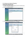
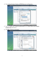
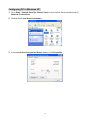
1
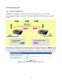
Wired / Wireless Internet Fiber Router FRT-401 / 401S15 / 405 FRT-401N / 401NS15 / 405 User's Manual 1 Copyright Copyright© 2010 by PLANET Technology Corp. All rights reserved. No part of this publication may be reproduced, transmitted, transcribed, stored in a retrieval system, or translated into any language or computer language, in any form or by any means, electronic, mechanical, magnetic, optical, chemical, manual or otherwise, without the prior written permission of PLANET. PLANET makes no representations or warranties, either expressed or implied, with respect to the contents hereof and specifically disclaims any warranties, merchantability or fitness for any particular purpose. Any software described in this manual is sold or licensed "as is". Should the programs prove defective following their purchase, the buyer (and not this company, its distributor, or its dealer) assumes the entire cost of all necessary servicing, repair, and any incidental or consequential damages resulting from any defect in the software. Further, this company reserves the right to revise this publication and to make changes from time to time in the contents hereof without obligation to notify any person of such revision or changes. All brand and product names mentioned in this manual are trademarks and/or registered trademarks of their respective holders. Federal Communication Commission Interference Statement This equipment has been tested and found to comply with the limits for a Class B digital device, pursuant to Part 15 of FCC Rules. These limits are designed to provide reasonable protection against harmful interference in a residential installation. This equipment generates, uses, and can radiate radio frequency energy and, if not installed and used in accordance with the instructions, may cause harmful interference to radio communications. However, there is no guarantee that interference will not occur in a particular installation. If this equipment does cause harmful interference to radio or television reception, which can be determined by turning the equipment off and on, the user is encouraged to try to correct the interference by one or more of the following measures: 1. Reorient or relocate the receiving antenna. 2. Increase the separation between the equipment and receiver. 3. Connect the equipment into an outlet on a circuit different from that to which the receiver is connected. 4. Consult the dealer or an experienced radio technician for help. FCC Caution To assure continued compliance (example-use only shielded interface cables when connecting to computer or peripheral devices). Any changes or modifications not expressly approved by the party responsible for compliance could void the user’s authority to operate the equipment. This device complies with Part 15 of the FCC Rules. Operation is subject to the Following two conditions: (1) This device may not cause harmful interference, and (2) this Device must accept any interference received, including interference that may cause undesired operation. Federal Communication Commission (FCC) Radiation Exposure Statement This equipment complies with FCC radiation exposure set forth for an uncontrolled environment. In order to avoid the possibility of exceeding the FCC radio frequency exposure limits, human proximity to the antenna shall not be less than 20 cm (8 inches) during normal operation. 2 CE mark Warning This is a class B device, in a domestic environment; this product may cause radio interference, in which case the user may be required to take adequate measures. Energy Saving Note of the Device This power required device does not support Stand by mode operation. For energy saving, please remove the DC-plug or push the hardware Power Switch to OFF position to disconnect the device from the power circuit. Without remove the DC-plug or switch off the device, the device will still consuming power from the power circuit. In the view of Saving the Energy and reduce the unnecessary power consuming, it is strongly suggested to switch off or remove the DC-plug for the device if this device is not intended to be active. R&TTE Compliance Statement This equipment complies with all the requirements of DIRECTIVE 1999/5/EC OF THE EUROPEAN PARLIAMENT AND THE COUNCIL OF 9 March 1999 on radio equipment and telecommunication terminal Equipment and the mutual recognition of their conformity (R&TTE) The R&TTE Directive repeals and replaces in the directive 98/13/EEC (Telecommunications Terminal Equipment and Satellite Earth Station Equipment) As of April 8, 2000. WEEE Regulation To avoid the potential effects on the environment and human health as a result of the presence of hazardous substances in electrical and electronic equipment, end users of electrical and electronic equipment should understand the meaning of the crossed-out wheeled bin symbol. Do not dispose of WEEE as unsorted municipal waste and have to collect such WEEE separately. Safety This equipment is designed with the utmost care for the safety of those who install and use it. However, special attention must be paid to the dangers of electric shock and static electricity when working with electrical equipment. All guidelines of this and of the computer manufacture must therefore be allowed at all times to ensure the safe use of the equipment. Revision User’s Manual for Wired / Wireless Internet Fiber Router Model : FRT-401 / 401S15 / 405 FRT-401N / 401NS15 / 405N Rev: 1.0 (Apr. 2010) Part No. EM-FRT40x_FRT40xN_v1.0 3 Table of Contents 1. INTRODUCTION ........................................................................................................................................................ 6 1.1 Feature ................................................................................................................................ 7 1.2 Package Contents .............................................................................................................. 7 1.3 Physical Details .................................................................................................................. 8 2. INSTALLATION........................................................................................................................................................ 12 2.1 System Requirement........................................................................................................ 12 2.2 Hardware Installation ....................................................................................................... 12 2.3 Configuring the Network Properties............................................................................... 15 2.4 Configuring with Web Browser ....................................................................................... 21 3. WEB CONFIGURATION MANAGEMENT .......................................................................................................... 23 3.1 Operation Mode ................................................................................................................ 24 3.2 Internet Settings ............................................................................................................... 25 3.2.1 WAN........................................................................................................................................................ 25 ¾ STATIC (FIXED IP) ...................................................................................................................... 25 ¾ DHCP (AUTO CONFIG)............................................................................................................... 26 ¾ PPPOE............................................................................................................................................. 27 ¾ L2TP ................................................................................................................................................ 28 ¾ PPTP ................................................................................................................................................ 30 3.2.2 LAN ......................................................................................................................................................... 31 3.2.3 DHCP clients ........................................................................................................................................... 32 3.2.4 Advanced Routing ................................................................................................................................... 33 3.2.5 QoS .......................................................................................................................................................... 34 3.3 Wireless Setting (For FRT-401N / 401NS15 / 405N) ....................................................... 35 3.3.1 Basic ........................................................................................................................................................ 35 3.3.2 Advanced ................................................................................................................................................. 37 3.3.3 Security .................................................................................................................................................... 39 3.3.4 WDS ........................................................................................................................................................ 41 3.3.5 WPS ......................................................................................................................................................... 43 3.3.6 Station List............................................................................................................................................... 44 3.4 Firewall .............................................................................................................................. 45 3.4.1 MAC/IP/Port Filtering ............................................................................................................................. 45 3.4.2 Port Forwarding (Virtual Server)............................................................................................................. 47 3.4.3 DMZ ........................................................................................................................................................ 48 4 3.4.4 System Security Settings.......................................................................................................................... 49 3.4.5 Content Filtering ...................................................................................................................................... 50 3.5 Fiber / OAM Setting .......................................................................................................... 51 3.5.1 Fiber Configuration.................................................................................................................................. 51 3.5.2 Remote Configuration.............................................................................................................................. 52 3.5.3 OAM Configuration................................................................................................................................. 54 3.5.4 Loop back test.......................................................................................................................................... 56 3.6 Administration .................................................................................................................. 59 3.6.1 Management ............................................................................................................................................ 59 3.6.2 Upload Firmware ..................................................................................................................................... 60 3.6.3 Setting Management ................................................................................................................................ 61 3.6.4 Reboot...................................................................................................................................................... 62 3.6.5 Status........................................................................................................................................................ 62 3.6.6 Statistics................................................................................................................................................... 63 3.6.7 System Log .............................................................................................................................................. 64 APPENDIX A.................................................................................................................................................................. 65 A.1 Device‘s RJ-45 Pin Assignments ................................................................................... 65 A.2 RJ-45 cable pin assignment............................................................................................ 65 A.3 Fiber Optical Cable Connection Parameter................................................................... 66 A.4 Available Modules............................................................................................................ 66 APPENDIX B: SPECIFICATION ................................................................................................................................ 67 APPENDIX C: GLOSSARY.......................................................................................................................................... 70 5 1. Introduction With growing network services such as HDTV, IPTV, voice-over-IP (VoIP) and Multimedia broadband applications, and the demand of bandwidth rises quickly. The current Broadband environment has not already accorded with needing; the FTTH (fiber-to-the-home) would be the most promising NGN (Next Generation Networking) application to fulfill the demand. The PLANET Wired / Wireless Internet Fiber Router, FRT-40x and FRT-40xN series, provides office and residential users the ideal solution for sharing a high-speed fiber Internet connection and four-10/100Mbps Fast Ethernet backbone. The Fiber Router is a perfect FTTH Digital Home Router which can provide very high performance access to Internet, both downstream and upstream up to 100Mbps through the fiber interface. The PLANET Internet Fiber Router supports several common optical connectors for WAN connection, such as 100BASE-BX, 100BASE-LX, 100BASE-FX and Small Form Factor Pluggable (SFP). The Fiber Router can be implemented easily for optical fiber deployment. With built-in IEEE 802.11b/g and 802.11n wireless network capability, the FRT-40xN series allows any computer and wireless-enabled network device connect to it without additional cabling. New 802.11n wireless capability gives you the highest speed of wireless experience ever. With a compatible wireless adapter installed in your PC, the files can be transferred at up to 300Mbps. The radio coverage is also doubled to offer the high speed wireless connection even in a wide space of your office or house. To secure the wireless communication, the FRT-40xN supports most up-to-date encryption, WEP, WPA-PSK and WPA2-PSK. In order to simplify the security settings, the FRT-40xN supports WPS configuration with PBC/PIN type for users to easily connect to a secured wireless network. The PLANET Fiber Router provides QoS features to make the network services smooth. Traffic priority can be assigned by the router to guarantee some important and specific transmissions, especially for real-time streaming multimedia applications such as the on-line gaming, VoIP, and IPTV to keep the bandwidth usage smoothly. Furthermore, the Fiber Router not only provides basic router functions such as DHCP server, Virtual Server, DMZ, and UPnP, but also provides full firewall functions including Network Address Translation (NAT), IP / Port / MAC Filtering and Content Filtering. It serves as an Internet firewall to protect your network from being accessed by unauthorized users. 6 1.1 Feature 1. Fiber Interface support 2. Complies with IEEE 802.3, IEEE 802.3u 10/100Base-TX, 100Base-FX standard 3. Long distance connection based on optical fiber transceiver 4. Choice of fiber-connector from SC, MT-RJ / VF-45 and WDM, multi-mode / single-mode fiber / 100Base SFP 5. Co-work with PLANET 100Base-FX Media Conversion and MFB-Series Transceiver 6. QoS support 7. 802.1Q VLAN support 8. Supports FTTH / IPTV applications 9. Built-in 4-port 10/100 Mbps Ethernet switch 10. Router / Bridge / WISP mode support (WISP mode is noly for wireless model) 11. SPI Firewall security for Anti-DoS Prevention 12. Supports IP / Port / MAC Filtering and Content Filtering 13. TS-1000 and 802.3ah OAM support 14. Supports SNMP v1/v2c 15. IEEE 802.11n wireless technology compliant with 802.11b/g standard (For wireless model) 16. Capable of up to 300Mbps wireless data rate (For wireless model) 17. WPS / WMM support (For wireless model) 18. Supports 64/128-bit WEP, WPA–TKIP(PSK), WPA2-AES(PSK), 802.1x (For wireless model) 1.2 Package Contents Wired / Wireless Fiber Router Unit x 1 Power Adapter x 1 Quick Installation Guide x 1 User’s Manual CD x 1 Antenna x 2 (Foe Wireless Model) 7 1.3 Physical Details FRT-401 / FRT-401S15 / FRT-405 Front Panel FRT-401 / FRT-401S15 FRT-405 Front Panel LED definition LED State Description ON When the router is powered on, and in ready state. OFF When the router is powered off. PWR Flashing Data is being transmitted or received via the fiber connection. WAN ON The optical fiber connection connected successfully. Flashing Data is being transmitted or received via the corresponding LAN port. LAN1-4 ON The port is up. 8 Front Panel FRT-401 / FRT-401S15 FRT-405 Rear Panel Port and Button Definition Connector Description POWER Power connector with 12V DC 1 A RESET Press more than 3 seconds for reset to factory default setting. LAN (1-4) WAN Router is successfully connected to a device through the corresponding port (1, 2, 3, or 4). If the LED light of LNK/ACT is flashing, the Router is actively sending or receiving data over that port. One Fiber-optic Interface, SC or SFP connector-type 9 FRT-401N / FRT-401NS15 / FRT-405N Front Panel FRT-401N / FRT-401NS15 FRT-405N Front Panel LED definition LED State Description ON When the router is powered on, and in ready state. OFF When the router is powered off. ON WPS client registration is successful. PWR WPS WLAN Flashing WPS client registration window is currently open. OFF WPS is not available, or WPS is not enabled or initialized. ON WLAN radio is on. Flashing Data is being transmitted through WLAN. OFF WLAN radio is off. ON Enable WLAN encryption OFF Disable WLAN encryption Security Flashing Data is being transmitted or received via the fiber connection. WAN ON The optical fiber connection connected successfully. Flashing Data is being transmitted or received via the corresponding LAN port. LAN1-4 ON The port is up. 10 Front Panel FRT-401N / FRT-401NS15 FRT-405N Rear Panel Port and Button Definition Connector Description POWER Power connector with 12V DC 1 A RESET Press more than 3 seconds for reset to factory default setting. LAN (1-4) Router is successfully connected to a device through the corresponding port (1, 2, 3, or 4). If the LED light of LNK/ACT is flashing, the Router is actively sending or receiving data over that port. WPS WPS on or off switch. WAN One Fiber-optic Interface, SC or SFP connector-type 11 2. Installation This chapter offers information about installing your router. If you are not familiar with the hardware or software parameters presented here, please consult your service provider for the values needed. 2.1 System Requirement 1. Personal computer (PC) 2. Pentium III 266 MHz processor or higher 3. 128 MB RAM minimum 4. 20 MB of free disk space minimum 5. RJ45 Ethernet Port 2.2 Hardware Installation This section describes how to install your Internet Fiber Router and make connections to the Fiber Network. Please read the following topics and perform the procedures in the order being presented. The hardware installation of PLANET Fiber Router do not need software configuration. To install your Fiber Router on a desktop or shelf, simply complete the following steps. 12 Connect the Fiber-optic cable to WAN port. Check the WAN LED on the front panel is on accordingly. The Fiber types of PLANET Wired / Wireless Fiber Router as the following: FRT-401 / FRT-401N: 100Base-FX (SC, MM) FRT-401S15 / FRT-401NS15: 100Base-FX (SC, SM, 15Km) FRT-405 / FRT-405N: 100Base-FX SFP (LC, MM/SM) FRT-401 / FRT-401N / FRT-401S15 / FRT-401NS15 13 FRT-405 / FRT-405N 14 2.3 Configuring the Network Properties Configuring PC in Windows Vista 1. Go to Start / Control Panel / Network and Internet / Network and Sharing Center. Double-click on Network Connections. 2. Double-click Local Area Connection. 3. In the Local Area Connection Status window, click Properties. 15 4. Select Internet Protocol Version 4 (TCP/IPv4) and click Properties. 5. Select the Obtain an IP address automatically and the Obtain DNS server address automatically radio buttons. 6. Click OK to finish the configuration. 16 Configuring PC in Windows XP 1. Go to Start / Control Panel (in Classic View). In the Control Panel, double-click on Network Connections 2. Double-click Local Area Connection. 3. In the Local Area Connection Status window, click Properties. 17 4. Select Internet Protocol (TCP/IP) and click Properties. 5. Select the Obtain an IP address automatically and the Obtain DNS server address automatically radio buttons. 6. Click OK to finish the configuration. 18 Configuring PC in Windows 2000 2. Go to Start / Settings / Control Panel. In the Control Panel, double-click on Network and Dial-up Connections. Double-click Local Area Connection. 3. In the Local Area Connection Status window click Properties. 4. Select Internet Protocol (TCP/IP) and click Properties. 5. Select the Obtain an IP address automatically and the Obtain DNS server address automatically radio buttons. 6. Click OK to finish the configuration. 1. 19 Configuring PC in Windows 98/Me 1. Go to Start / Settings / Control Panel. In the Control Panel, double-click on Network and choose the Configuration tab. 2. Select TCP/IP Æ NE2000 Compatible, or the name of your Network Interface Card (NIC) in your PC. 3. Select the Obtain an IP address automatically radio button. 4. Then select the DNS Configuration tab. 5. Select the Disable DNS radio button and click OK to finish the configuration. 20 2.4 Configuring with Web Browser It is advisable to change the administrator password to safeguard the security of your network. To configure the router, open your browser, type “http: //192.168.1.1” into the address bar and click “Go” to get to the login page. Save this address in your Favorites for future reference. At the User name and Password prompt, type your proper user name and password to login. The default user name / password are “admin / admin”. You can change these later if you wish. Click “OK”. 21 If the user name and password are correct, you will login Fiber Router successfully and see the status page. Now you can configure the Fiber Router for your needs. 22 3. Web Configuration Management Determine your connection settings Before you configure the router, you need to know the connection information supplied by your service provider. Connecting the Fiber Router to your network Unlike a simple hub or switch, the setup of the Fiber Router consists of more than simply plugging everything together. Because the Router acts as a DHCP server, you will have to set some values within the Router, and also configure your networked PCs to accept the IP Addresses the Router chooses to assign them. Generally there are several different operating modes for your applications. And you can know which mode is necessary for your system from ISP. These modes are router, bridge, and PPPoE+NAT. Configuring with Web Browser It is advisable to change the administrator password to safeguard the security of your network. To configure the router, open your browser, type “http: //192.168.1.1” into the address bar and click “Go” to get to the login page. Save this address in your Favorites for future reference. At the User name prompt, type “admin”. And the Password prompt, type “admin”. You can change these later if you wish. Click “OK” to login the router and you can start to configure it now. 23 3.1 Operation Mode The Fiber Router supports three operation modes – Router, Bridge and WISP (WISP mode is only supported for wireless fiber router). Currently, it comes pre-configured with Router mode. Note that, routing mode and bridging mode cannot be used simultaneously. For Bridge mode, all interfaces are bridged into a single bridge interface. For Router mode, the Fiber port is treated as WAN port. The other interfaces are bridged together and are treated as LAN ports. For WISP Mode (For wireless model), all the Ethernet ports are bridged together and the wireless interface of this router will connect to ISP’s Access Point. The NAT is enabled and PCs in Ethernet ports share the same IP to ISP through wireless LAN. The connection type can be setup in WAN page by using PPPoE, DHCP client, PPTP/L2TP client or static IP. If you select Bridge operation mode, WAN configuration in Internet Settings are not available. (Firewall functions on the left page are not available.) After finishing setting, click Apply to save the settings and make the new configuration take effect. Click Cancel to close without saving. 24 3.2 Internet Settings 3.2.1 WAN The WAN Settings screen allows you to specify the type of Internet connection. The WAN settings offer the following selections for the router’s WAN port, STATIC (fixed IP), DHCP (Auto config), PPPoE, L2TP, and PPTP. ¾ STATIC (FIXED IP) Select STATIC (fixed IP) in the WAN Connection Type drop-down list and the following page appears. 25 Static Mode IP Address: Enter the IP address of WAN port. Subnet Mask: Enter IP subnet mask of WAN port. Default Gateway: Enter the default gateway address of WAN port. Primary DNS Server: Primary DNS Server f of WAN port. Secondary DNS Server: Secondary DNS Server of WAN port. MAC Clone MAC Clone provides WAN to connect to a MAC address. Enabled: Enable or disable MAC clone. After finishing setting, click Apply to save the settings and make the new configuration take effect. Click Cancel to close without saving. ¾ DHCP (AUTO CONFIG) Select DHCP (Auto config) in the WAN Connection Type drop-down list and the following page appears. If the WAN connection type is set to DHCP, the device automatically obtains the IP address, gateway and DNS address from the DHCP server on WAN interface. MAC Clone MAC Clone provides WAN to connect to a MAC address. Enabled: Enable or disable MAC clone. After finishing setting, click Apply to save the settings and make the new configuration take effect. Click Cancel to close without saving. 26 ¾ PPPOE Select PPPoE (ADSL) in the WAN Connection Type drop-down list and the following page appears. If the WAN connection type is set to PPPoE, you can configure the following parameters to PPPoE dial up. PPPoE Mode User Name: User name of PPPoE account Password: Password of PPPoE account Verify Password: Enter the password of PPPoE account again. Operation Mode: It provides two types of operation modes. Keep Alive means keeping on-line mode. You can set the redial period in the field. When the redial period expires, Router will execute dial-up again to keep online. On Demand means executing dial-up on demand. Within the preset idle time, if Router does not detect the flow of the user continuously, Router automatically stops the PPPOE connection. Once it detects the flow (e.g., accessing a webpage), the router restarts the PPPOE dial-up. MAC Clone Enabled: Enable or disable. After finishing setting, click Apply to save the settings and make the new configuration take effect. Click Cancel to close without saving. 27 ¾ L2TP Select L2TP in the WAN Connection Type drop-down list and the following page appears. There are two address modes: Static and Dynamic. 1. If you select Static in the Address Mode field, the page shown in the following figure appears. 2. If you select Dynamic in the Address Mode field, the page shown in the following figure appears. 28 L2TP Mode Server IP: Address of L2TP server. User Name: The user name of L2TP account. Password: The password of L2TP account. IP Address: IP address of WAN port. Subnet Mask: Subnet mask of WAN port. Default Gateway: The default gate way of WAN port. Operation Mode: It provides two types of operation modes. Keep Alive means keeping on-line mode. You can set the redial period in the field. When the redial period expires, Router will execute dial-up again to keep online. On Demand means executing dial-up on demand. Within the preset idle time, if Router does not detect the flow of the user continuously, Router automatically stops the PPPOE connection. Once it detects the flow (e.g., accessing a webpage), the router restarts the PPPOE dial-up. MAC Clone Enabled: Enable or disable. After finishing setting, click Apply to save the settings and make the new configuration take effect. Click Cancel to close without saving. 29 ¾ PPTP Select PPTP in the WAN Connection Type drop-down list and the following page appears. There are two address modes: Static and Dynamic. PPTP Mode Server IP: Address of PPTP server. User Name: The user name of PPTP account. Password: The password of PPTP account. IP Address: IP address of WAN port. Subnet Mask: Subnet mask of WAN port. Default Gateway: The default gate way of WAN port. Operation Mode: It provides two types of operation modes. Keep Alive means keeping on-line mode. You can set the redial period in the field. When the redial period expires, Router will execute dial-up again to keep online. On Demand means executing dial-up on demand. Within the preset idle time, if Router does not detect the flow of the user continuously, Router automatically stops the PPPOE connection. Once it detects the flow (e.g., accessing a webpage), the router restarts the PPPOE dial-up. MAC Clone Enabled: Enable or disable. After finishing setting, click Apply to save the settings and make the new configuration take effect. Click Cancel to close without saving. 30 3.2.2 LAN This page allows you may enable or disable networking functions and configure their parameters according to your practice. IP Address: Enter the IP address of LAN port. Subnet mask: Enter the subnet mask of LAN port. LAN2: The second IP switch of LAN port. You can enable or disable this function. LAN2 IP Address: The second IP address of LAN port. LAN2 Subnet Mask: The second IP Subnet Mask of LAN port. MAC Address: MAC address of LAN port (Read-only). DHCP Type: You can select Server or Disable. If you select Disable, the DHCP service of LAN port is disabled. After selecting Server, you can set the following items. Start IP Address: The first IP address that DHCP server assigns. End IP Address: The last IP address that DHCP server assigns. Subnet Mask: The subnet mask of dynamic IP. 31 Primary DNS Server: The primary DNS server address. Secondary DNS Server: The secondary DNS Server address. Default Gateway: The default gateway that DHCP server assigns. Lease Time: Lease time of the IP address. Statically Assigned: Assign IP to the assigned MAC address. Enter the assigned MAC address and IP in the corresponding fields. 802.1d Spanning Tree: Spanning Tree Protocol. You can select Enable or Disable. IGMP Proxy: You can select Enable or Disable. UPNP: Universal Plug and Play (UPNP).You can select Enable or Disable. Router Advertisement: You can select Enable or Disable. DNS Proxy: You can select Enable or Disable. After finishing setting, click Apply to save the settings and make the new configuration take effect. Click Cancel to close without saving. 3.2.3 DHCP clients You can view the information about DHCP clients in the page. 32 3.2.4 Advanced Routing You can add or delete routing rules, enable or disable dynamic routing protocol in the page. Add a routing rule Destination: Enter the legal destination IP address. Range: Destination IP address is a host address or the network address. Gateway: Enter the specific gateway. Interface: The interface for this route. You can select LAN, WAN and Custom. Comment: Add the description of this route. After finishing the setting above, click Apply to make the new routing rule take effect. Otherwise, click Reset to cancel the new routing rule. Current Routing table in the system You can delete or reset the routing rules. Dynamic Routing Settings You can enable or disable the RIP. After finishing the setting above, click Apply to make the new routing rule take effect. Otherwise, click Reset to cancel the new routing rule. 33 3.2.5 QoS You may set up rules to provide Quality of Service (QoS) guarantee for some specific applications. In the page, you can enable or disable Quality of Service. After enabling QoS, you can set upload bandwidth and download bandwidth. Upload Bandwidth: You can select the proper bandwidth in the drop-down list. The value is from 64K to 60M. You can also set the bandwidth by selecting User defined and enter the proper bandwidth in the field. Download Bandwidth: You can select the proper bandwidth in the drop-down list. The value is from 64K to 60M. You can also set the bandwidth by select User defined and enter the proper bandwidth in the field. After finishing the setting above, click Submit to save the new configuration. 34 3.3 Wireless Setting (For FRT-401N / 401NS15 / 405N) 3.3.1 Basic You can configure the minimum number of wireless settings for communication, such as network name (SSID) and channel. Wireless Network Radio On/Off: Enable or disable the wireless LAN. Network Mode: There are 6 modes: 11b only, 11g only, 11n only, 11b/g mixed, and 11b/g/n mixed mode. Network Name (SSID): The service set identification (SSID) is a unique name to identify the router in the wireless LAN. Wireless stations associating to the router must have the same SSID. Enter a descriptive name. Its length is up to 32 characters. Multiple SSID 1/2/3/4/5: There are 5 multiple SSIDs. Enter their descriptive names that you want to use. Broadcast Network Name (SSID): Select Enable to allow the SSID broadcast on the network, so that the STA can find it. Otherwise, the STA can not find it. AP Isolation: Enable or disable AP Isolation. When many clients connect to the same access point, they can access each other. If you want to disable the access between clients which connect the same access point, you can enable this function. MBSSID AP Isolation: Enable or disable MBSSID AP Isolation. BSSID: Basic Service Set Identifier. This is the assigned MAC address of the station in the access point. This unique identifier is in Hex format and can only be edited when Multi BSSID is enabled in the previous screen. 35 Frequency (Channel): A channel is the radio frequency used by wireless device. Channels available depend on your geographical area. You may have a choice of channels (for your region) and you should use a different channel from an adjacent AP to reduce the interference. The Interference and degrading performance occurs when radio signals from different APs overlap. HT Physical Mode HT Physical Mode Operation Mode: Select Mixed Mode or Green Field. Channel Bandwidth: Select 20 or 20/40. Guard Interval: Select Long or Auto. MCS: Select the proper value between 0 and15 or 32. Auto is the default value. Reverse Direction Grant (RDG): Select Disable or Enable. Extension Channel: Select the proper extension channel in the drop-down list. Aggregation MSDU (A-MSDU): Select Disable or Enable. Auto Block ACK: Select Disable or Enable. Decline BA Request: Select Disable or Enable. 36 3.3.2 Advanced This page makes more detailed settings for the AP. Advanced Wireless Settings page includes items that are not available in the Basic Wireless Settings page, such as basic data rates, beacon interval, and data beacon rate. Advanced Wireless BG Protection Mode: It provides 3 options, including Auto, On, and Off. The default BG protection mode is Auto. Beacon Interval: The interval time range is between 20ms and 999ms for each beacon transmission. The default value is 100ms. Date Beacon Rate (DTM): The DTM range is between 1 ms and 255 ms. The default value is 1ms. Fragment Threshold: This is the maximum data fragment size (between 256 bytes and 2346 bytes) that can be sent in the wireless network before the router fragments the packet into smaller data frames. The default value is 2346. RTS Threshold: Request to send (RTS) is designed to prevent collisions due to hidden node. A RTS defines the biggest size data frame you can send before a RTS handshake invoked. The RTS threshold value is between 1 and 2347. The default value is 2347. If the RTS threshold value is greater than the fragment threshold value, the RTS handshake does not occur. Because the data frames are fragmented before they reach the RTS size. Tx Power: The Tx Power range is between 1 and 100. The default value is 100. Short Preamble: Select Disable or Enable. 37 Short Slot: Select Disable or Enable. Tx Burst: Select Disable or Enable. Pkt_Aggregate: Select Disable or Enable. Country Code: Select the region which area you are. It provides six regions in the drop-down list. Wi-Fi Multimedia WMM Capable: Enable or disable WMM. APSD Capable: Enable or disable APSD. WMM Parameter: Click WMM Configuration button to pop up WMM Parameters of Access Point page. You can configure WMM parameters in the page. Multicast-to-Unicast Converter Multicast-to-Unicast Converter: Enable or disable Multicast-to-Unicast Converter. After finishing the settings above, click Apply to save the settings and make the new configuration take effect. Click Cancel to close without saving. 38 3.3.3 Security Choose Wireless Settings>Security and the following page appears. It allows you to modify the settings to prevent the unauthorized accesses. Select SSID SSID choice: Select SSID in the drop-down list. Security Security Mode: There are 11 options, including Disable, OPEN, SHARED, WEPAUTO, WPA, WPA-PSK, WPA2, WPA2-PSK, WPAPSKWPA2PSK, WPA1WPA2, and 802.1X. [EXAMPLE] Take 802.1x for example. Select 802.1x in the Security Mode down-list. The page shown in the following page appears. 39 WEP: Disable or enable WEP. Radius Server IP Address: Enter the IP address of Radius Server. Port: The default port of the RADIUS server for authentication is 1812. You need not change this value unless your network administrator instructs you to do so with additional information. Shared Secret: Enter a password as the key to be shared between the external authentication server and the access point. The key is not send over the network. This key must be the same on the external authentication server and your router. Session Timeout: Set the time interval for session. Enter the proper value in the field. Idle Timeout: Set the idle time interval. Enter the proper value in the field. Access Policy Policy: There are three options, including Disable, Allow, and Reject. You can choose Disable, Allow or Reject. Select Allow, only the clients whose MAC address is listed can access the router. Select Reject, the clients whose MAC address is listed are denied to access the router. Add a station MAC: If you want to add a station MAC, enter the MAC address of the wireless station that are allowed or denied access to your router in this address field. After finishing the settings above, click Apply to save the settings and make the new configuration take effect. Click Cancel to close without saving. 40 3.3.4 WDS Wireless Distribution System (WDS) WDS Mode: There are four options, including Disable, Lazy Mode, Bridge Mode, and Repeater Mode. ¾ Disable Select Disable to disable the WDS mode. ¾ Lazy Mode WDS Mode: Select Lazy Mode. The FRT-40xN WDS Lazy mode is allowed the other FRT-40xN WDS bridge / repeater mode link automatically. Phy Mode: It provides 4 options, including CCK, OFDM, HTMIX, and GREENFIELD. Encryp Type: It provides 4 options, including None, WEP, TKIP, and AES. ¾ Bridge Mode/ Repeater Mode WDS Mode: Select Bridge Mode or Repeater Mode. Phy Mode: It provides 4 options, including CCK, OFDM, HTMIX, and GREENFIELD. Encryp Type: It provides 4 options, including None, WEP, TKIP, and AES. AP MAC Address: It provides 4 AP MAC Address. Enter the MAC address of the other APs. 41 WDS (Wireless Distribution System) allows access points to communicate with one another wirelessly in a standardized way. It can also simplify the network infrastructure by reducing the amount of cabling required. Basically the access points will act as a client and an access point at the same time. WDS is incompatible with WPA. Both features cannot be used at the same time. A WDS link is bi-directional, so the AP must know the MAC address of the other AP, and the other AP must have a WDS link back to the AP. Dynamically assigned and rotated encryption key are not supported in a WDS connection. This means that WPA and other dynamic key assignment technologies may not be used. Only Static WEP keys may be used in a WDS connection, including any STAs that are associated with a WDS repeating AP. Enter the MAC address of the other APs that you want to link to and click enable. Supports up to 4 point to multipoint WDS links, check Enable WDS and then enable on the MAC addresses. Example of a WDS topology: AP1 <-- WDS --> Master AP (our AP) <-- WDS --> AP3<-- WDS --> AP4 42 3.3.5 WPS You can enable or disable the WPS function in this page. Select Enable in the WPS drop-down list. Click Apply and the following page appear. WPS Summary It displays the WPS information, such as WPS Current Status, WPS Configured, and WPS SSID. Reset OOB: Reset to out of box (OoB) configuration WPS Progress WPS mode: There are two way for you to enable WPS function: PIN, PBC. You can use a push button configuration (PBC) on the Wi-Fi router. If there is no button, enter a 4- or 8-digit PIN code. Each STA supporting WPS comes with a hard-coded PIN code. PIN: If you select PIN mode, you need enter the PIN number in the field. WPS Status It displays the information about WPS status. 43 3.3.6 Station List Through this page, you can easily identify the connected wireless stations. It automatically observes the ID of connected wireless station (if specified), MAC address, SSID, and current status. 44 3.4 Firewall The Fiber Router provides the fully firewall functions, such as IP/Port/MAC Filtering, Port Forwarding, DMZ, SPI Firewall and Content Filtering. It serves as an Internet firewall to protect your network from being accessed by outside users. 3.4.1 MAC/IP/Port Filtering Use the MAC/IP/Port filters to deny / allow particular LAN IP addresses from accessing the Internet. You can deny / allow specific port numbers or all ports for a specific IP address. You may set up firewall rules to protect your network from malicious activity on the Internet. It is also convenient for you to delete these settings. 45 Basic Settings MAC/IP/Port Filtering: Enable or disable the MAC/IP/Port filtering function. Default Policy: The Packet that does not match any rules would be dropped or accepted. MAC/IP/Port Filter Settings MAC Address: Enter the MAC address that matches the source address of the packet (optional). Dest IP Address: Enter the IP address that matches the destination address of the packet (optional). Source IP Address: Enter the IP address that matches the source address of the packet (optional). Protocol: There are 4 options, including none, TCP, UDP and ICMP. Dest Port Range: After setting a valid protocol, you may enter the UPD or TCP destination port range. Source Port Range: After setting a valid protocol, you may enter the UPD or TCP source port range. Action: Select Drop or Accept in the drop down list. Comment: Add description for this rule. Click Apply to make the configuration take effect. Click Reset to cancel the new configuration. The maximal rule number you can add is 32. Current MAC/IP/Port filtering rules in system If you want to delete some rules in the table above, select the rules, and then click Delete Selected. Otherwise, click Reset. 46 3.4.2 Port Forwarding (Virtual Server) The Virtual Server is the server or server(s) behind NAT (on the LAN), for example, Web server or FTP server, that you can make visible to the outside world even though NAT makes your whole inside network appear as a single machine to the outside world. This page allows you to set virtual server to provide services on the Internet. Virtual Server Settings Virtual Server Settings: Enable or disable this function. After selecting Enable, you can set the following parameters. Protocol: There are 3 options, including none, TCP& UDP, TCP, and UDP. WAN Port Range: You can setup your port range for your WAN side. Server IP Address: Enter the virtual server IP address in internal network. Server Host Port: Set the port range of your virtual server. Comment: Add description for this rule. The maximal rule number you can add is 32. Click Apply to make the configuration take effect. Click Reset to cancel the new configuration. 47 3.4.3 DMZ DMZ (Demilitarized Zone) allows a single computer on your LAN to expose ALL of its ports to the Internet. Enter the IP address of that computer as a DMZ (Demilitarized Zone) host with unrestricted Internet access. When doing this, the DMZ host is no longer behind the firewall. This page allows you to set a De-militarized Zone (DMZ) to separate internal network and Internet. DMZ Settings: Enable or disable this function. After selecting Enable, you can set the DMZ IP address. DMZ IP Address: Enter the DMZ host IP address. Click Apply to make the configuration take effect. Click Reset to cancel the new configuration. 48 3.4.4 System Security Settings Choose Firewall > System Security and the following page appears. This page allows you to configure the system firewall to protect Router from attacking. Remote Management Remote management (via WAN): Deny or allow remote management through web. Remote management Port: The default remote management port is 80, you can change the remote management port for your needs. Ex. 8080. Ping from WAN Filter Ping from WAN Filter: You may select enable or disable to determine whether to filter the ping package which comes from the external network. Stateful Packet Inspection (SPI) SPI Firewall: You may disable or enable the SPI firewall. Click Apply to make the configuration take effect. Click Reset to cancel the new configuration. 49 3.4.5 Content Filtering This page is used to configure the Blocked URL (Such as tw.yahoo.com) and filtered keyword. Here you can add / delete URL and filtered keyword. Choose Firewall > Content Filtering and the following page appears. You can set content filter to restrict the improper content access. Webs Content Filters: If you want to block some applications as Proxy, Java and ActiveX of web pages please select the check box and click “Apply”. Current Webs URL Filters: If you want to delete some filters in the table above, select the rules, and then click Delete. Otherwise, click Reset. Add a URL filter URL: Enter the URL String and click “Add” to apply this URL filter rule. Click Add to add a URL filter. Otherwise, click Reset to cancel the URL filter. The URL Filter allows you to block access to undesirable Web site To use this feature, you must define "filter strings". If the "filter string" appears in a requested URL, the request is blocked. 50 3.5 Fiber / OAM Setting 3.5.1 Fiber Configuration This function allows displaying the Fiber port’s status, Mode, Flow Control and Rate limit. The Link Status in the screen displays the current connection speed and duplex mode. • Flow Control • Ingress Rate Limit • Egress Shaping Allow Enable or Disable flow control for selected port. • Enable – 802.3x flow control is enabled on Full-Duplex mode or Backpressure is enabled on Half-Duplex mode • Disable – No flow control or backpressure function on no matter Full-Duplex or Half-Duplex mode Default value: Disable The value of inbound traffic limitation in kilobit-per-second (kbps). The possible values are : • No Limit • 512K • 1M • 2M • 4M • 8M • 10M • 50M Default value: No Limit The value of outbound traffic limitation in kilobit-per-second (kbps). The possible values are : • No Limit • 512K • 1M • 2M • 4M • 8M • 10M • 50M Default value : No Limit 51 3.5.2 Remote Configuration The Remote TS-1000 Configuration is an advanced remote device monitor feature that allows you to Remote monitor and automatic notify status indication. Remote TS-1000 OAM Information The Fiber Router supports the TS-1000 and 802.3ah OAM, you can check the status and information of remote device by OAM. Click the “Get” to gat the OAM information from remote devices. It will show the IP, MAC and Port status. TS-1000 OAM function must work with manageable device #Notice: The that supports TS-1000 OAM function. Remote System Configuration The users can manage the remote device from local Fiber Router; you can setup the IP address, reset and restore factory default for remote device. 1. IP address: Enter the IP address and click the “Change”, it will modify the IP address of remote device. 52 2. Reset: Click the “Reset” button to reboot the remote device. 3. Factory: Click the “Factory” button to restore the default settings of remote device. Remote Port Configuration The users can manage the remote port from local Fiber Router; you can setup the Port Mode, Flow Control, Rate Limit for remote device. 53 3.5.3 OAM Configuration 802.3ah OAM Configuration When enable 802.3ah OAM function, all 802.3ah OAMPDU packets will trap to embedded CPU. Software will implement auto discovery procedure. With hardware support, software controls the 802.3ah remote loop back procedure. Hardware can also detect dying gasp even and interrupt CPU to send dying gasp even notification OAMPDU. All other functions defined by 802.3ah are implemented using embedded CPU. When remote device is in loop back mode, hardware can support change looped test frame’s DA, SA or both as user defined. Hardware can also set to don't change looped test frame. This function provides 802.3ah Setup of Managed Media Converter. Press the “Apply” button to save the current configuration of Managed Media Converter. Below Figure and Table describes the 802.3ah Setup object of Managed Media Converter. The 802.3ah OAM Configuration Web page includes the following configurable data: 802.3ah OAM State 802.3ah OAM Mode Loopback Reply Provide disable or enable the 802.3ah OAM State function. Default mode is Enable. Allow to choose “Active” or “Passive” for 802.3ah OAM Mode. Provide disable or enable the Loopback Reply function. Default mode is Enable. Provide disable or enable the Remote OAM Configure function. Default mode is Enable. Display the Remote OAM Configuration Result. Remote OAM Configure Remote OAM Configuration Result Apply button Press this button for save current configuration of Managed Media Converter. Table Descriptions of the 802.3ah Setup Web Page Screen Objects 54 Local TS-1000 OAM Configuration Local TS-1000 OAM Setup This function provides Local TS-1000 OAM Setup of Managed Media Converter. Press the “Apply” button to save the current configuration of Managed Media Converter. The below screen and Table describes the Local TS-1000 OAM Setup object of Managed Media Converter. Figure Local TS-1000 OAM Setup Web Page screen The Local TS-1000 OAM Setup Web page includes the following configurable data: TS-1000 OAM State Provide disable or enable the TS-1000 OAM operation mode. TS-1000 Mode Provide two TS-1000 modes for operation, the available options are: Terminal Center Provide disable or enable the Link Transparent function. Default mode is Disable. Display the link transparent result. Link Transparent Link Transparent Result Apply button Press this button for save current configuration of Managed Media Converter. Table Descriptions of the Local TS-1000 OAM Setup Web Page Screen Objects TS-1000 OAM function must work with manageable device #Notice: The that supports TS-1000 OAM function. 55 3.5.4 Loop back test 802.3ah Loop Back Test The 802.3ah Loop Back Test allows manual run this loop back test to check the interconnection between two devices. To assure the Remote 802.3ah function can work correctly. This function provides 802.3ah Loop Back Test of Fiber devices. Press the “Apply” button to run 802.3ah Loop Back Test and see the 802.3ah Loop Back Test Result of Fiber devices. The below screen and Table describes the 802.3ah Loop Back Test object of Fiber Router. Figure 802.3ah Loop Back Test Web Page screen 56 The 802.3ah Loop Back Test Web page includes the following configurable data: 802.3ah Loop Back Test Send Packet Number Allow input the number for packet send and the available options is 1 to 255. Default is 16. Packet Length (Not include CRC) Allow input the number for Packet Length and the available Apply button Press this button for save current configuration of Fiber Router. options is 60 to 1514. Default is 60. 802.3ah Loop Back Test Result Result Display the 802.3ah Loop Back Test Result. Fail or Pass. Table Descriptions of the 802.3ah Loop Back Test Web Page Screen Objects 802.3ah function must work with manageable device that #Notice: The supports 802.3ah function. TS-1000 Loop Back Test The TS-1000 Loop Back Test allows manual run this loop back test to check the interconnection between two Fiber devices. To assure the Remote TS-1000 OAM function can work correctly. 57 In-band and out-band Loop back This function provides TS-1000 Loop Back Test of Fiber devices. Press the “Apply” button to run Loop Back Test and see the TS-1000 Loop Back Test Result of Fiber Route. The below screen and Table describes the TS-1000 Loop Back Test object of Managed Media Converter. Figure Remote TS-1000 Loop Back Test Web Page screen The TS-1000 Loop Back Test Web page includes the following configurable data: TS-1000 Loop Back Test Send Packet Number Allow input the number for packet send and the available Apply button Press this button for save current configuration of Fiber Router. options is 1 to 255. Default is 16. TS-1000 Loop Back Test Result Result Display the TS-1000 Loop Back Test Result. Fail or Pass. Result counter Display the value of Counter Result. Table Descriptions of the TS-1000 Loop Back Test Web Page Screen Objects TS-1000 OAM function must work with manageable device #Notice: The that supports TS-1000 OAM function. 58 3.6 Administration You can configure admin management in this part. It includes Management, Update Firmware, Setting management, Reboot, Status, Statistics and System Log. 3.6.1 Management Choose Administration > Management, and the following page appears. You may configure administrator account and password, NTP settings, and dynamic DNS settings in the page. Administrator Settings Account: Enter the username of the administrator in the field. Password: Enter the password of the administrator in the field. NTP Settings Current Time: Display the current date and time. Click Sync with host, the current time is synchronized by your PC which is connected to Router. 59 Time Zone: Select the proper time zone in the drop-down list. NTP Server: Enter the IP address or domain name of NTP server. NTP Synchronization (hours): Enter the time interval for synchronization. DDNS Settings Dynamic DNS Provider: Select the proper dynamic DNS provider in the drop-down list. After selecting a dynamic DNS provider, you are allowed to set the following parameters. Account: Enter the username of DDNS provider in the field. Password: Enter the password of DDNS provider in the field. DDNS: Enter the domain name of your device. Click Apply to make the configuration take effect. Click Cancel to cancel the new configuration. 3.6.2 Upload Firmware Choose Administration > Upload Firmware and the following page appears. In this page, you may upgrade the correct new version firmware to obtain new functionality. It takes about 1 minute to upload upgrade flash. If the firmware is uploaded in an improper way, the system would core dump. Update Firmware Location: Click Browse to select the firmware file, and click Apply to upgrade the firmware. 60 3.6.3 Setting Management Choose Administration > Settings Management and the following page appears. You may save system settings by exporting them to a configuration file, restore them by importing the file, or reset them to the factory default. Export Settings Export Button: Click the Export to export the settings. Import Settings Settings file location: Click Browse to select the configuration file, and then click Import to upload the configuration file. Click Cancel to cancel the uploading operation. Load Factory Defaults Load Default Button: Click Load Default to make Router return to the default settings. 61 3.6.4 Reboot The Reboot screen allows you to restart your router with its current settings. Click the “Reboot” button and the device will restart. 3.6.5 Status Choose Administration > Status and the following page appears. It displays the information about Router status, including system information, Internet configurations, and local network. 62 3.6.6 Statistics You can see the Statistic information in this screen. It includes the Traffic for all interfaces. 63 3.6.7 System Log The system log dialog allows you to view the system log and click the “Refresh” button to fresh the system event logs. Choose Administration > System Log and the following page appears. You are allowed to view and disable / enable the system log in this page. Click Refresh to refresh the log. Click Clear to clear the log. 64 Appendix A A.1 Device‘s RJ-45 Pin Assignments ■ 10/100Mbps, 10/100Base-TX Contact MDI MDI-X 1 1 (TX +) 3 2 2 (TX -) 6 3 3 (RX +) 1 6 6 (RX -) 2 4, 5, 7, 8 Not used Not used Implicit implementation of the crossover function within a twisted-pair cable, or at a wiring panel, while not expressly forbidden, is beyond the scope of this standard. A.2 RJ-45 cable pin assignment 6 32 1 6 321 6 3 21 There are 8 wires on a standard UTP/STP cable and each wire is color-coded. The following shows the pin allocation and color of straight cable and crossover cable connection: Figure A-1: Straight-Through and Crossover Cable Please make sure your connected cables are with same pin assignment and color as above picture before deploying the cables into your network. 65 A.3 Fiber Optical Cable Connection Parameter The wiring details are as below: ■ Fiber Optical patch Cables: Standard Fiber Type Cable Specification 100Base-FX Multi-mode 50/125μm or 62.5/125μm 100Base-FX Multi-mode 50/125μm or 62.5/125μm (1310nm) Single-mode 9/125μm 100Base-BX-U Single-mode 9/125μm (1300nm) (TX :1310/RX :1550) 100Base-BX-D (TX :1550/RX :1310) A.4 Available Modules The following list the available Modules for FRT-40x / 40xN MFB-FX SFP-Port 100Base-FX Transceiver (1310nm) -2km MFB-F20 SFP-Port 100Base-FX Transceiver (1310nm) - 20km MFB-FA20 SFP-Port 100Base-BX Transceiver (WDM,TX:1310nm) -20km MFB-FB20 SFP-Port 100Base-BX Transceiver (WDM,TX:1550nm) -20km 66 Appendix B: Specification FRT-401 / FRT-401S15 / FRT-405 Product Model Ports Internet Fiber Router FRT-401 WAN 1 x 100Base-FX port LAN 4 x 10/100Base-TX port Connector Optic Interface FRT-401S15 SC Mode Single-mode Vary on module 2km 15km Vary on module 850nm 1310nm - Max. -14 -7 - Min. -19.0 -20 - -34.5 -28 - -14 -8 - Optic wavelength Receive Sensitivity Maximum Input power Fiber-optic cable LED Indicators Button Software SFP Multi-mode Distance Launch Power(dBm) FRT-405 50/125μm or 62.5/125μm multi-mode fiber cable, up to 2km. 9/125μm single-mode cable, provide long distance for 15/20/35/50km or longer (very on SFP module) PWR, Fiber, LAN1-4 1 x RESET button Max. Sessions 4096 Protocol / Feature Router and Bridge mode Static Routing and RIPv1/2 DMZ and Virtual Server 802.1D 802.1Q VLAN support QoS SNTP DHCP Server / Client IGMP Proxy and DNS Proxy Universal Plug and Play (UPnP) Compliant DDNS (Dynamic Domain Name System) VPN VPN Pass-Through Security Built-in NAT Firewall MAC / IP/ Port Filtering Content Filtering SPI Firewall support Password protection for system management Management Web-based configuration Available Syslog support TR-069* SNMP v1/v2c TS-1000 and 802.3ah OAM support * Feature Enhance by Future FW upgradeable. 67 FRT-401N / FRT-401NS15 / FRT-405N Product Model 802.11n Wireless Internet Fiber Router FRT-401N FRT-401NS15 Ports WAN 1 x 100Base-FX port LAN 4 x 10/100Base-TX port Wireless 1 x 802.11b/g/n Access Point, 2 x antennas detachable Connector Optic Interface SC Mode Single-mode Vary on module 2km 15km Vary on module 850nm 1310nm - Max. -14 -7 - Min. -19.0 -20 - -34.5 -28 - -14 -8 - Optic wavelength Launch Power(dBm) SFP Multi-mode Distance Receive Sensitivity Maximum Input power Fiber-optic cable LED Indicators Button Software 50/125μm or 62.5/125μm multi-mode fiber cable, up to 2km. 9/125μm single-mode cable, provide long distance for 15/20/35/50km or longer (very on SFP module) PWR, WPS, WLAN, Security, Fiber, LAN1-4 1 x RESET button, 1 x WPS button Max. Sessions 4096 Protocol / Feature Router, Bridge and WISP mode WDS and WPS Static Routing and RIPv1/2 DMZ and Virtual Server 802.1D 802.1Q VLAN support QoS SNTP DHCP Server / Client IGMP Proxy and DNS Proxy Universal Plug and Play (UPnP) Compliant DDNS (Dynamic Domain Name System) Wireless VPN FRT-405N Wireless Standard Compliant with IEEE 802.11n, 802.11g and 802.11b standards Frequency 2.4 to 2.4835GHz (Industrial Scientific Medical Band ) Channels Maximum 14 Channels, depending on regulatory authorities Antenna 2 x 2dBi detachable Antenna Wireless Data Encryption 64 bit / 128 bit WEP, WPA-PSK, WPA, WPA2, 802.1x encryption, and WPS PBC Wireless Data Rate IEEE 802.11b: 1/2/5.5/11Mbps IEEE 802.11g: 6/9/12/18/24/36/48/54Mbps IEEE 802.11n: 14/29/43/58/87/116/130/144Mps in 20MHz, 30/60/90/120/180/240/270/300Mbps in 40MHz WDS WDS repeater support VPN Pass-Through 68 Security Built-in NAT Firewall MAC / IP/ Port Filtering Content Filtering SPI Firewall support Password protection for system management Management Web-based configuration Available Syslog support TR-069* SNMP v1/v2c TS-1000 and 802.3ah OAM support * Feature Enhance by Future FW upgradeable. 69 Appendix C: Glossary Address mask A bit mask select bits from an Internet address for subnet addressing. The mask is 32 bits long and selects the network portion of the Internet address and one or more bits of the local portion. Sometimes it called subnet mask. VDSL2 VDSL2 (Very High-Bit-Rate Digital Subscriber Line 2), G.993.2 is the newest and most advanced standard of xDSL broadband wire line communications. ADSL Asymmetric digital subscriber line AAL5 ATM Adaptation Layer - This layer maps higher layer user data into ATM cells, making the data suitable for transport through the ATM network. ATM Asynchronous Transfer Mode - A cell-based data transfer technique in which channel demand determines packet allocation. ATM offers fast packet technology, real time, and demand led switching for efficient use of network resources. AWG American Wire Gauge - The measurement of thickness of a wire Bridge A device connects two or more physical networks and forward packets between them. Bridges can usually be made to filter packets, that is, to forward only certain traffic. Related devices are repeaters which simply forward electrical signals from one cable to the other and full-fledged routers which make routing decisions based on several criteria. Broadband Characteristic of any network multiplexes independent network carriers onto a single cable. Broadband technology allows several networks to coexist on one single cable; traffic from one network does not interfere with traffic from another. Broadcast a packet delivery system where a copy of a given packet is given to all hosts attached to the network. Example: Ethernet. 70 CO Central Office. Refers to equipment located at a Telco or service provider's office. CPE Customer Premises Equipment located in a user's premises DHCP (Dynamic Host Configuration Protocol) DHCP is software that automatically assigns IP addresses to client stations logging onto a TCP/IP network. DHCP eliminates having to manually assign permanent IP addresses to every device on your network. DHCP software typically runs in servers and is also found in network devices such as Routers. DMT Discrete Multi-Tone frequency signal modulation Downstream rate The line rate for return messages or data transfers from the network machine to the user's premises machine. DSLAM Digital Subscriber Line Access Multiplex Dynamic IP Addresses A dynamic IP address is an IP address that is automatically assigned to a client station (computer, printer, etc.) in a TCP/IP network. Dynamic IP addresses are typically assigned by a DHCP server, which can be a computer on the network or another piece of hardware, such as the Router. A dynamic IP address may change every time your computer connects to the network. Encapsulation The technique layer protocols in which a layer adds header information to the protocol data unit (PDU) from the layer above. As an example, in Internet terminology, a packet would contain a header from the physical layer, followed by a header from the network layer (IP), followed by a header from the transport layer (TCP), and followed by the application protocol data. Ethernet One of the most common local area network (LAN) wiring schemes, Ethernet has a transmission rate of 10 Mbps. 71 FTP File Transfer Protocol. The Internet protocol (and program) transfer files between hosts. Hop count A measure of distance between two points on the Internet. It is equivalent to the number of gateways that separate the source and destination. HTML Hypertext Markup Language - The page-coding language for the World Wide Web. HTML browser A browser used to traverse the Internet, such as Netscape or Microsoft Internet Explorer. http Hypertext Transfer Protocol - The protocol carry world-wide-web (www) traffic between a www browser computer and the www server being accessed. ICMP Internet Control Message Protocol - The protocol handle errors and control messages at the IP layer. ICMP is actually part of the IP protocol. Internet address An IP address is assigned in blocks of numbers to user organizations accessing the Internet. These addresses are established by the United States Department of Defense's Network Information Center. Duplicate addresses can cause major problems on the network, but the NIC trusts organizations to use individual addresses responsibly. Each address is a 32-bit address in the form of x.x.x.x where x is an eight- bit number from 0 to 255. There are three classes: A, B and C, depending on how many computers on the site are likely to be connected. Internet Protocol (IP) The network layer protocol for the Internet protocol suite IP address The 32-bit address assigned to hosts that want to participate in a TCP/IP Internet. ISP Internet service provider - A company allows home and corporate users to connect to the Internet. 72 MAC Media Access Control Layer - A sub-layer of the Data Link Layer (Layer 2) of the ISO OSI Model responsible for media control. MIB Management Information Base - A collection of objects can be accessed via a network management protocol, such as SNMP and CMIP (Common Management Information Protocol). NAT Network Address Translation - A proposal for IP address reuse, where the local IP address is mapped to a globally unique address. NVT Network Virtual Terminal PAP Password Authentication Protocol PORT The abstraction used in Internet transport protocols to distinguish among multiple simultaneous connections to a single destination host. POTS Plain Old Telephone Service - This is the term describe basic telephone service. PPP Point-to-Point-Protocol - The successor to SLIP, PPP provides router-to-router and host-to-network connections over both synchronous and asynchronous circuits. PPPoE PPP over Ethernet is a protocol for connecting remote hosts to the Internet over an always-on connection by simulating a dial-up connection. Remote server A network computer allows a user to log on to the network from a distant location. 73 RFC Request for Comments - Refers to documents published by the Internet Engineering Task Force (IETF) proposing standard protocols and procedures for the Internet. RFC can be found at www.ietf.org. Route The path that network traffic takes from its source to its destination. The route a datagram may follow can include many gateways and many physical networks. In the Internet, each datagram is routed separately. Router A system is responsible for making decisions about which of several paths network (or Internet) traffic will follow. To do this, it uses a routing protocol to gain information about the network and algorithms to choose the best route based on several criteria known as "routing metrics". Routing Table Information stored within a router that contains network path and status information. It is used to select the most appropriate route to forward information along. Routing Information Protocol Routers periodically exchange information with one another so that they can determine minimum distance paths between sources and destinations. SNMP Simple Network Management Protocol - The network management protocol of choice for TCP/IP-based Internet. SOCKET (1) The Berkeley UNIX mechanism for creating a virtual connection between processes. (2) IBM term for software interfaces that allow two UNIX application programs to talk via TCP/IP protocols. Spanning-Tree Bridge Protocol (STP) Spanning-Tree Bridge Protocol (STP) - Part of an IEEE standard. A mechanism for detecting and preventing loops from occurring in a multi-bridged environment. When three or more LAN's segments are connected via bridges, a loop can occur. Because of a bridge forwards all packets that are not recognized as being local, some packets can circulate for long periods of time, eventually degrading system performance. This algorithm ensures only one path connects any pair of stations, selecting 74 one bridge as the 'root' bridge, with the highest priority one as identifier, from which all paths should radiate. Spoofing A method of fooling network end stations into believing that keep alive signals have come from and returned to the host. Polls are received and returned locally at either end Static IP Address A static IP address is an IP address permanently assigned to computer in a TCP/IP network. Static IP addresses are usually assigned to networked devices that are consistently accessed by multiple users, such as Server PCs, or printers. If you are using your Router to share your cable or DSL Internet connection, contact your ISP to see if they have assigned your home a static IP address. You will need that address during your Router's configuration. Subnet For routing purposes, IP networks can be divided into logical subnets by using a subnet mask. Values below those of the mask are valid addresses on the subnet. TCP Transmission Control Protocol - The major transport protocol in the Internet suite of protocols provides reliable, connection-oriented full-duplex streams. TFTP Trivial File Transfer Protocol. A simple file transfer protocol (a simplified version of FTP) that is often boot diskless workstations and other network devices such as routers over a network (typically a LAN). Telnet The virtual terminal protocol in the Internet suite of protocols - Allows users of one host to log into a remote host and act as normal terminal users of that host. Transparent bridging The intelligence necessary to make relaying decisions exists in the bridge itself and is thus transparent to the communicating workstations. It involves frame forwarding, learning workstation addresses, and ensuring no topology loops exist (in conjunction with the Spanning-Tree algorithm). 75 UDP User Datagram Protocol - A connectionless transport protocol that runs on top of TCP/IP's IP. UDP, like TCP, uses IP for delivery; however, unlike TCP, UDP provides for exchange of datagram without acknowledgments or guaranteed delivery. Best suited for small, independent requests, such as requesting a MIB value from an SNMP agent, in which first setting up a connection would take more time than sending the data. UNI signaling User Network Interface signaling for ATM communications. Virtual Connection (VC) A link that seems and behaves like a dedicated point-to-point line or a system that delivers packets in sequence, as happens on an actual point-to-point network. In reality, the data is delivered across a network via the most appropriate route. The sending and receiving devices do not have to be aware of the options and the route is chosen only when a message is sent. There is no pre-arrangement, so each virtual connection exists only for the duration of that one transmission. WAN Wide area network - A data communications network that spans any distance and is usually provided by a public carrier (such as a telephone company or service provider). 76