1
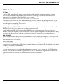
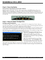
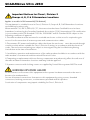
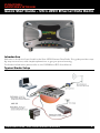
CONTROL
MICROSYSTEMS
Quick Start Guide – Ultra JR5O Ethernet Data Radio
Introduction
Welcome to the Quick Start Guide for the Ultra JR50 Ethernet Data Radio. This guide provides stepby-step instructions, with simple explanations to get you up-and-running.
For further information, please refer to the SCADAWave JR50 User Manual.
Typical Radio Setup
Quick Start Guide - Ultra JR50 Ethernet Data Radio
1
SCADAWave Ultra JR5O
Mounting and Installation Instructions
The radio should be mounted in a clean and dry location, protected from water, excessive dust,
corrosive fumes, extremes of temperature and direct sunlight. In high power or high temperature
applications, please allow sufficient passive or active ventilation. To avoid moisture ingress
mount the radio with the connectors facing downwards.
Please choose an enclosure that is suitable for the size of the radio : Dimensions are 100 x 34 x
165mm (4.0 x 1.4 x 6.5 inches).The radio is rated for use in ambient (operating) environments
from -40 C to +70 C.
Connecting Antennas and RF Feeders
The RF antenna system should be installed in accordance with the
manufacturers notes. Antenna gain must be considered when setting Transmit Power. Refer to
Compliance notices at the end of this document and in the use manual for more information.
The RF connectors on this product are TNC Type female connectors. Always use good quality
low loss feeder cable, selected according to the length of the cable run. Ensure all external
connections are waterproofed.
O
O
Power Supply Requirements
Tx: Nominal 13.8 Volts DC @ 800 mA (Max 1A)
Rx: Nominal 13.8 Volts DC @ 150 mA
Rated Operating Voltage 10 - 30 Volts DC
Power Supply Protection and Precautions
The J Series Radio is supplied with the a mating DC power connector: Phoenix Contact Part Number
1777989. The DC Power connector should be installed with the locking screws done up tightly. Cable
must be #22 AWG or larger, 70o C min. temperature rating. CSA maximum current rating: 2.5A.
The J Series Ethernet radio modem will operate from a 10 to 30 volt (filtered) DC supply. The radio is
designed to self protect from permanent damage if the voltage exceeds 30V dc or if reverse polarity
is applied. The replaceable internal fuse has a rating 3 Amp.
The current requirement is typically 180mA @ 13.8 V DC in receive mode, and will vary in transmit
mode according to RF output power level & duty cycle.
The radio modem can also be damaged if there is any potential difference between the
chassis-ground, RS232 signal ground, power (-) input, or antenna coaxial shield.
Before connecting any wiring, ensure all components are earthed to a common ground
point (please pay particular attention to 24V PLC power systems where converters are used).
Connect the antenna,ethernet and RS 232 plugs BEFORE applying power to the unit. Lastly, before inserting the power plug, please re-check that the polarity and voltage on the DC power plug
is correct using a multimeter.
2
Quick Start Guide - Ultra JR50 Ethernet Data Radio
Quick Start Guide
Communication Ports
LAN 1 and LAN 2 Ethernet Ports
The LAN 1 and LAN 2 ports are 10/100 Base-T compliant ports using an RJ-45 connector. These
ports support both TIA/EIA-568-A & B wiring as they have Auto MDI/MIDX Auto Sensing. This
means you can use both straight-through and cross-over type CAT-5 or better patch cables.
If termination of a cable is
required, then the following wiring
arrangement should be followed
(Compliant with TIA/EIA-568-A).
Note: Maximum differential voltage :
5v, 50mA max through each
differential pair.
Note: If 100-BaseT connection speed
is required, CAT-6 Shielded cable
should be used for installation to
comply with ETSI EMC directives.
Serial Port A & B Ports
The J Series Radio features a 9 pin miniature D-Shell (DE-9)
Female connector that supports two individual serial port
connections. Each serial port is associated with an embedded
serial terminal server that provides the RS-232 to TCP/UDP IP
connectivity. Refer to the user manual for more information on the serial terminal servers.
Data Port A uses pins 2, 3, 7 & 8 with pin 5 as the common ground.
Data Port B uses pins 4 & 6 with pin 5 as the common ground.
An RSSI output is available on pin 9 which is useful for antenna alignment. See below for details.
Notes:
(1) Pin 2, 6 & 8 are outputs rated at +/- 6v,
65mA max.
(2) Pin 3, 4 & 7 are inputs rated at +/- 15v,
5mA max.
(3) Pin 9 is a multipurpose IO pin with 120mA
max input / 5mA max output.
(4) Connecting wires should be #26 AWG or
larger.
Quick Start Guide - Ultra JR50 Ethernet Data Radio
3
SCADAWave Ultra JR5O
Optimising the Antenna for Rx Signal
When using a directional antenna, it will be necessary to align the antenna for the best received
signal. This can be done using TVIEW+ Diagnostics or by measuring the RSSI output on Pin 9 of
the serial data port. RSSI voltage of 2.5v is approx. -90dBm. Slope is equal to 20dB/volt.
4
Quick Start Guide - Ultra JR50 Ethernet Data Radio
Quick Start Guide
LED Indicators
DC Power
If all the LEDs are off, no DC power is reaching the radio modem or the internal fuse is open.
Successful power-up is indicated by the Pwr/Tx LED showing a continuous GREEN state for
Remotes or an alternating Red/Green for Access Points.
When the transmitter is active the Pwr/Tx LED is in a RED state.
Note: The J Series radio will take approximately 45 seconds to boot up - during this time, the DC
power LED will remain solid green and various LED activity may occur. Please wait at least 45
seconds before attempting to use radio.
Received Signal Indicator
A regular flashing GREEN LED indicates that the modem is synchronised to its Access Point. The
GREEN LED will also flash when the modem is receiving data.
A regular flashing RED LED indicates the REMOTE is not synchronised to a Access Point or
BRIDGE. Check the antenna, all RF connections, and the radio configuration as the Subnet ID may
not match the Access Point or there may be insufficient RX signal or too much interference.
LAN 1 & LAN 2
The Red TxD and Green RxD LEDs indicate ethernet status on the two LAN ports. These LEDs will
show solid Green when an Ethernet Link is established and will flash Orange to indicate Ethernet
data transmission is occurring.
Port A Data Flow
The RxD/TxD LEDs indicate data flow into/out of the user port. Data being sent to the port for
transmission is indicated by a RED flash, and data being received over the air and then sent from
the port is shown as a GREEN flash.
Error LED Indications
In some circumstances the radio will indicate an error state. This is shown as all LEDs flashing
RED for 1 sec and then a pattern of green LEDs for 1 sec. The pattern of green LEDs indicate the
type of error. Please consult the user manual for further information.
Quick Start Guide - Ultra JR50 Ethernet Data Radio
5
SCADAWave Ultra JR5O
J Series Configuration (Web Interface)
Introduction and Warnings:
Please read the following notes carefully. Configuration errors with Ethernet connections can be
difficult to find and resolve. It is strongly recommended that you follow these guidelines.
IP Address and Factory Default Reset
The factory default IP address of the J Series is 192.168.2.15. If you do not know the IP
address of the J Series you will need to activate a factory reset.
A factory reset will cause all previous configuration settings to be erased and returned to the
factory default values. A factory default can be initiated by applying DC power to the radio (wait
45 seconds), depress the factory default switch using a paper clip or similar object and keep the
switch depressed for 5 seconds until all five LEDs illuminate solid GREEN indicating the radio
will return to the factory default settings. Please wait 30 seconds for the factory default reset
process to complete.
Connection to Embedded HTML Web Server
The J Series radio contains an embedded Web Server. To change a configuration parameter in the
J Series you will need to connect your PC to one of the Ethernet Ports (LAN1 or LAN2) and direct
your browser to the IP address of the J Series. It is strongly recommended that you follow these
guidelines for successful connection to the radio:
(1) Ensure the J Series is powered up and has fully booted. This is indicated by a solid green
power LED and a flashing Synch/NoRx LED. It takes approximately 45 seconds from applying DC
power for the J Series to fully power up.
(2) Disconnect your PC from any other Internet/LAN networks. Failure to do so may create a
conflict in IP addresses or the J Series IP might not meet the subnet mask specified by your
network.
(3) Connect your PC Ethernet Port to one of the Ethernet Ports (LAN 1 or LAN2) using an RJ-45
patch cable. Cross over cables will also work. Successful cable connection is indicated by a solid
Green “Link” LED on the Ethernet Port.
Note: The LAN1/2 LEDs will also flash orange when data is being transferred.
(4) Ensure your PC LAN Port is configured for a suitable IP address. You can do this by
configuring the LAN settings via the Control Panel. Navigate to your Windows “Start” button and
open Control Panel -> Network Connections -> Local Area Connection -> Properties.
Scroll Down and Select “Internet Protocol (TCP/IP) and then click on Properties. You will now see
the window as shown.
Ensure “Obtain IP Address Automatically” is not selected. It is recommended that you manually
specify a compatible IP Address. In this example, a factory default radio is being configured. The
6
Quick Start Guide - Ultra JR50 Ethernet Data Radio
Quick Start Guide
IP address of that radio is 192.168.2.15 and
a compatible IP address for the PC would be
192.168.2.1. Click OK to accept the changes.
Note: Check with your Network Administrator
before allocating IP addresses as each LAN/
WAN network is different.
(5) You should start your web browser and
insert the IP address of the J Series into the
URL. In this case, we type “192.168.2.15” and
the configuration page is now displayed in the
browser.
Note: You may need to disable a web proxy (if
in use) or disable or modify your local firewall
to ensure the security rules allow access to
the J Series IP address.
Quick Start Guide - Ultra JR50 Ethernet Data Radio
7
SCADAWave Ultra JR5O
Resolving Ethernet Configuration Problems
Here are some basic tips to help you along the way with Ethernet configuration problems. The
Windows operating system (and others) comes complete with many useful tools. First, you need
to open a command window. This can be done by clicking on “Start” then “Run” and entering
“CMD” and clicking OK.
Obtaining IP information about
your PC
If you need to find out more
information about your
computers Ethernet IP
configuration, network gateways
and DNS servers, you can use
a tool called “IPConfig”. Simply
type “IPconfig /all” into your command
window.
Checking IP connectivity
The most reliable way to check IP connectivity
to a device is using the “Ping” utility. Type
“ping xxx” where xxx is the complete IP
address of the destination device you want to
check. Ping with either respond with latency
results (as shown) or say “timed out” if no
connection was possible.
Repeated connections to multiple devices with same IP address
A common problem experienced when attempting to configure multiple radios with the same IP
address (such as factory default radios). The problem is due to invalid MAC table entries. If you
change your ethernet connection between two devices with the same IP address quickly, you
may need to reset the MAC look up table in your PC. You can do this by typing “arp -d *” in the
command window.
8
Quick Start Guide - Ultra JR50 Ethernet Data Radio
Quick Start Guide
Step by Step
Point to Point Link Setup
Introduction
This document describes the 10 key steps required for configuring the radio and demonstrating
remote diagnostics on a pair of J Series radios operating in Point to Point ( PTP ) mode. After
successful diagnostics polling is achieved, subsequent testing can then be done on user
equipment such as RTUs or PLCs.
For more information consult the following documents:
n JR 50 User Manual
n SCADAWave Manager Diagnostics User Manual
Typical Radio Setup
Step 1 - RF and DC power connection
RF Connection
It is recommended that whip antennas are not used to simulate a long distance
RF link. RF attenuators are far superior to antennas for short-distance bench testing as the
attenuation of the RF signals between both radios is consistent and is not subject to external
interference. Alternatively 90dB of separation can be achieved with 50 ohm dummy loads or
small whip antennas (minimum separation 1m or 3ft).
(1) If the TX power of each radio is set to 20dBm (100mW) then low power, low cost
attenuators can be used.
(2) Small whip antennas can also be used, but the signal into the receiving radio should be no
greater than -30dBm (set Tx power on all radios to 20dBm).
DC Power Connection
Ensure each radio is wired using the correct polarity and that power supply
is regulated and has adequate current delivering capacity.
Quick Start Guide - Ultra JR50 Ethernet Data Radio
9
SCADAWave Ultra JR5O
Step 2 - Power Up Radios
Nominal Power Supply Requirements 13.8V @ 500 mA
Apply DC power to the radios. The “Pwr” LED should now be solid GREEN. Wait for 45 secs for
the radio to boot. If the radio is configured as a Remote (factory default) the LED will be solid
GREEN. If it flashes RED/GREEN it is configured as a Access Point. If there is no LED indication, the
internal fuse may have opened. Re-check the DC polarity and ensure the DC voltage are between
10V and 30V.
Step 3 - Setup for Radio Configuration
IP Address and Factory Default
The default IP address of the J Series radio is 192.168.2.15. To configure the J Series radio you
must know the IP address of the radio. If you are uncertain of the current IP programmed into the
radio you will need to reset the radio configuration to factory default.
This can be done by powering up the radio (wait 45 seconds), depress the factory default switch
using a paper clip or similar thin blunt wire and keep the switch depressed for 5 seconds. All 5
LEDs will illuminate solid GREEN indicating the radio will return to factory default settings. Please
wait 30 seconds with the factory default reset process to occur.
Connection to Embedded HTML Web Server
Connect your PC LAN Port to one of the
Ethernet Ports (LAN1 or LAN2). To verify you
can communicate with the J Series you should
first ping the radio.
Open up a command window on your PC by
going to the “Start” -> Run and typing “CMD”
then OK. Then type “ping 192.168.2.15” which
is the default address of the radio. If both the
radio and PC have their LAN port connection and configuration correct, the radio will respond to
the ping as shown above. If this is not the case, check you network settings as described on the
opposite page.
10
Quick Start Guide - Ultra JR50 Ethernet Data Radio
Quick Start Guide
Step 4 - Start Web Browser on your PC
Start your web browser and insert the IP
address of the J Series into the URL. In
this case, we type “192.168.2.15” and the
configuration page is now displayed in the
browser.
Click on the “Wizards” button to activate the
Wizards menu in the HTML configuration
programmer.
Step 5 - Activate Access Point PTP Wizard
Select Point to Point - Access Point
Select the “Point to Point - Access Point” button
and click on the “Start The Wizard” button. The Access Point Wizard screen is now shown.
The Wizard now prompts the user to configure some critical items for point to point operation.
For each configuration item, help text is provided on the HTML programmer interface. If you are
manually specifying IP addresses, ensure you record them for future reference. You will need to
know the IP address of each radio in future steps.
Note: The SubNet ID should be a descriptive text name for the radio link. It MUST be identical
in both Access Point and Remote radios for correct operation to occur. You can not save the
configuration with the factory default SubNet ID. Choose a unique ID and make sure it is
recorded.Up to 20 printable characters can be used.
After configuration of all items are complete, activate the configuration by clicking on the
“Activate Configuration” button in the top right corner.
Click on the “Write” button to send this configuration to the radio
Quick Start Guide - Ultra JR50 Ethernet Data Radio
11
SCADAWave Ultra JR5O
Step 6 - Activate Remote - PTP Wizard
Repeat steps (3) to (6) for the Remote radio.
Step 7 - Verify Modem Operation
The J Series Ethernet radio modems are now ready for operation. Allow 15 seconds for the
Remote radio to synchronise with the Access Point radio
Access Point LEDs
Pwr/Tx LED will be solid Green but flash Red once per second on Tx.
Remote Rx
Pwr/Tx LED will be Green and Sync/NoRX LED will flash Green once per second indicating the Remote has synchronized with the Access Point.
Step 8- Embedded Diagnostics Testing
8.1 Review Access Point.
Start your web browser and insert the IP address of the J Series Access Point (as recorded in Step
6) into the URL. Once loaded, click on the Diagnostics option. This will display the Diagnostics
summary page. Review the diagnostics parameters checking for abnormal items such as high
VSWR (high TX reverse power) and lower than expected radio RSSI (Received Signal Strength).
8.2 Review Remote Radio.
Click on the sub-menu “Browse Network”. The remote radio will appear in the list (serial number
and unit type is listed). Click on the Serial Number of the Remote Radio. The browser will now
re-direct to the Remote radio. Click on the “Summary” TAB and the remote radios diagnostics can
now be reviewed.
12
Quick Start Guide - Ultra JR50 Ethernet Data Radio
Quick Start Guide
Step 9 - Packet Error Testing
This tool provides a useful way to test a radio
communications link by
transmitting data packets between two units in a loopbacked mode.
To start the test, direct the browser to Access Point by
typing the IP address of this unit into your URL. Select the
“Diagnostics” menu and click on the “Packet Error Testing”
sub-menu.
Enter the “Destination Serial Number” of the Remote radio
and ensure the “Number of Packets” is set to 1000. Now
click on the “Start Packet Test” button. The radio will indicate
the packet test has started and is currently running.
When the test is complete, a note stating “Packet error test
completed” will be shown and the test results summarized
in the “Test Results” section.
The test results show TX & RX Packets, Lost Packets and the Packet Error Rate.
Step 10 - Commissioning Record
After an Indicative Packet Error test has been performed,
a Commissioning Record can be prepared. This facility
is activated by clicking on the “Commissioning Record”
button.
It is recommended that the radio is configured to obtain
the current date / time from an NTP server, otherwise the
date / time shown may not be correct.
The user can enter an appropriate Unit Name and
Location for reference purposes. Additionally, a comment
may be added noting the type of antenna in use. Once
this information has been added, the web page can be
printed (using the print facility in your web browser). It
may be useful to print the commissioning record to PDF
for future reference.
This now completes the requirements for setting up a Point to Point J Series Link. The radios are
now ready for application testing. The application can be connected to either LAN1 or LAN2 or
both (as required). For more information on testing, please consult the J Series User Manual.
Quick Start Guide - Ultra JR50 Ethernet Data Radio
13
SCADAWave Ultra JR5O
Important Notices for Class I, Division 2
Groups A, B, C & D Hazardous Locations
Applies to models Jx900-xxxxx-xHx(CSA Marked)
This equipment is suitable for use in Class I, Division 2, Groups A, B, C & D Hazardous Locations
and ordinary locations only.
When marked “CL I, DIV 2, GRP A, B, C, D”, the transceiver has been Certified for use in these
hazardous locations by the Canadian Standards Association ( CSA ) International. CSA certification
is in accordance with CSA Standard C22.2 No. 213-M1987 and UL Standard 1604 subject to the
following conditions of approval:
1.The radio modem must be mounted in a suitable enclosure so that a tool is required to gain
access for disconnection of antenna, power and communication cables
2.The antenna, DC power and interface cables that leave the enclosure must be routed through
conduit or other means suitable for Class I, Division 2 wiring, in accordance with the electrical
codes. The enclosure and wiring are subject to investigation by the local Authority Having
Jurisdiction at the time of installation.
3. Installation, operation and maintenance of the radio modem should be in accordance with the
radio modem’s user manual and the national Electrical Codes.
4. Tampering or replacement with non-factory components may adversely affect the safe use of
the radio modem in hazardous locations and may void the approval
5. A power connector with locking screws as supplied by Control Microsystems MUST be used
WARNING EXPLOSION HAZARD
Do not connect or disconnect this equipment unless power has been removed or the area is
known to be nonhazardous.
Secure all external connections that mate to this equipment by using screws, threaded
connectors, latching connectors, or other means provided with this product
Sustitution of components may impair suitability for Class I, Division 2.
14
Quick Start Guide - Ultra JR50 Ethernet Data Radio
Quick Start Guide
FCC Compliance Notices
FCC Part 15 Notice
This device complies with Part 15 of the FCC Rules. Operation is subject to the following two conditions: (1) this device may not cause harmful interference, and (2) this device must accept any
interference received including interference that may cause undesired operation.
FCC Approved Antennas
This device can only be used with Antennas listed in the Appendix of the SCADAWave JR50 User
Manual. Please Contact Control Microsystems if you need more information or would like to order
an antenna.
RF Exposure
To satisfy FCC RF exposure requirements for mobile transmitting devices, a separation distance
of 23 cm or more should be maintained between the antenna of this device and persons
during device operation. To ensure compliance, operations at closer than this distance is not
recommended. The antenna used for this transmitter must not be co-located in conjunction
with any other antenna or transmitter.
MAXIMUM EIRP
FCC Regulations allow up to 36 dBm effective isotropic radiated power (EIRP). Therefore, the sum of the
transmitted power (in dBm), the cabling loss and the antenna gain (in dBi) cannot exceed 36 dBm.
AUSTRALIAN COMPLIANCE NOTICE: MAXIMUM EIRP
ACMA Regulations allow up to 30 dBm (1 Watt) of effective isotropic radiated power (EIRP) in
the 915MHz license free band and 36 dBm (4 Watts) of EIRP in the 2.4GHz band. Therefore, the
sum of the transmitted power (in dBm), the cabling loss and the antenna gain cannot exceed the
above stated EIRP limits.
Contact
www.controlmicrosystems.com
The Control Microsystems web site has links to e-mail and telephone support, technical notes, manuals, and
software updates.
Quick Start Guide - Ultra JR50 Ethernet Data Radio
15
SCADAWave Ultra JR5O
Quick Start Guide
CONTROL
MICROSYSTEMS
w ww.c ontro lm icro s yste m s .com
Ottawa n Calgary n Denver n Houston n Melbourne n Leiden
Within Nor th America: (888) 267-2232 n Outside Nor th America: (613) 591-1943
Control Microsystems reserves the right to change product specifications without notice.
Printed in Canada n V006 n 250236
16
Quick Start Guide - Ultra JR50 Ethernet Data Radio