1
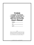
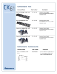
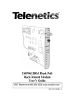
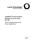
TC1900
"QUICK TALK"
RS-232 or Fiber
Telephone Extender
User's Manual
MODEL:
S/N:
DATE:
Notice!
Although every effort has been made to insure that this manual is current
and accurate as of date of publication, no guarantee is given or implied
that this document is error free or accurate with regard to any specification. TC Communications, Inc. reserves the right to change or modify
the contents of this manual at any time without prior notification.
©
COPYRIGHT 1992-2001 . ALL RIGHTS RESERVED.
ARC Electronics 800-926-0226 [email protected]
TC1900
User's Manual
Rev. 1.3
Table Of Contents
Chapter 1 - Overview ................................................................................................................ 3
Features ............................................................................................................................................. 3
Description ......................................................................................................................................... 3
Front Panel ......................................................................................................................................... 4
Rear Panel ......................................................................................................................................... 5
Front Panel LEDs, DIP Switches ....................................................................................................... 6
LEDs: ........................................................................................................................................... 6
DIP Switches: .............................................................................................................................. 6
Rear Panel Connectors and Switches ......................................................................................... 7
Power Jacks: ............................................................................................................................... 7
DB9 Female Connector:............................................................................................................... 7
RJ11 Connector for "LINE": ......................................................................................................... 8
RJ11 Connector for "PHONE": .................................................................................................... 8
Slide Switch for "FXS" and "FXO" ................................................................................................ 8
Dry Contact Relay Terminal Blocks: ............................................................................................ 8
Application Example 1: Hotlink Phone via RS-232 Async Channel ................................................ 10
Application Example 2: Dial Up Phone Extension via RS-232 Async Channel ................................ 11
Chapter 2 - Installation ........................................................................................................... 12
Unpacking the Unit...........................................................................................................................
Equipment Location ..........................................................................................................................
Power Supply ...................................................................................................................................
Electrical Signal Connection ............................................................................................................
The DIP switches Setting and LEDs Status ....................................................................................
System Start Up and Operation for "hotlink" ....................................................................................
DB9 Cable Connection between two TC1900s ...............................................................................
12
12
12
12
12
13
13
Chapter 3 - Testing & Troubleshooting ................................................................................ 14
General ............................................................................................................................................
Local Loopback Testing ...................................................................................................................
Remote Loopback Testing ...............................................................................................................
Return Policy ...................................................................................................................................
Warranty ...........................................................................................................................................
14
14
14
15
15
Appendix A ............................................................................................................................. 16
Appendix B ............................................................................................................................. 17
Glossary ........................................................................................................................................... 17
-2-
Chapter 1 - Overview
TC1900
User's Manual
Rev. 1.3
Features
S 2-wire Analog Telephone Voice to Async RS-232 or Optional Fiber Optic Signal
S Toll Voice Quality with Ringdown Capability
S FXS or FXO switchable
S RS-232 Async Data Rate Down to 9600 Baud
S LEDs Indicate Volume, Ringing Status and FXO/FXS
S FPGA Technology (Field Programmable Array) Consumes Low Power
S Various Power Voltage Available: 12VDC, 24VDC, 48VDC or 115VAC to 240VAC.
S Stand Alone or Rackmount
Description
The TC1900 "Quick Talk" is designed specifically for adding telephone connection via existing asynchronous
RS-232 channel or fiber optic cables. It supports telephone set and FXS/FXO connection.
The voice picked up by a handset's mouth piece (connected to TC1900) is digitized by a built-in CODEC
(code and decode) chip and further compressed to lower data rates. The voice data stream is converted to
an asynchronous bit stream and transmitted by RS-232 transmitter. The RS-232 link can take many forms,
such as a Satellite data link or one of the data channels provided by a TDM (time division multiplexer) such
as the TC8116 or TC2800.
When a bit stream is received by the remote matching TC1900 the compressed voice bit stream is extracted
from the asynchronous bit stream and then expanded. Finally, the expanded voice bit stream is sent to the
CODEC chip to restore the voice signal. Then, the handset's ear piece converts the voice signal to sound.
When digitized voice signals are being exchanged via a RS-232 link, the status of "off-hook", "on-hook" and
"ring" are also be being embedded in the bit stream. Therefore, a local TC1900 can detect remote hook status
or if a "ring" signal has been sent by the remote TC1900.
Since a regular telephone set is used and TC1900 has built-in ringing generator, the process to place a call is
depicted as follows:
Initiate a call:
When two TC1900s (connected by RS-232 link or fiber optic cables) are first
powered up, both units are in "idle" status, which is referred to as "on-hook" status
for a regular telephone set. The local TC1900 places a "call" by lifting the handset to
ring the remote telephone set.
Answer the call:
When a remote TC1900 is ringing by the local TC1900 the remote user can answer
the call by lifting the handset.
Terminate the call:
Either the local or remote user can terminate the call by placing the handset back to
the hook.
The LEDs on the front panel show the power status, ringing signal, voice volume picked up by local phone's
mouth piece and the voice volume received from remote peer. TC1900 has a built-in dry contact relay to
provide external alarm and ring connection. The standard power supply is 12VDC at 250mA. Power options
include 24VDC, 48VDC, or AC to DC power adaptor which can be ordered for a 110VAC or 220VAC power
supply.
-3-
TC1900
User's Manual
Rev. 1.3
Front Panel
Tx
Rx
4 5 6 7 8
11 22 33 4
RMT LB
LOCLB
DIS ALM
E/O
BAUD3
BAUD2
BAUD1
ASYNC/SYNC
BAUD RATE
9.6K
19.2K
32K
38.4K
RxB
TxA
QUICK-TALK
ALARM POWER
A
ALM
PWR
SYNC
B
FXS
VccA
FXO
VDC
RING
48K
56K
57.6K
64K
VOLUME
2
Alarm
Optic or RS-232 Signal Status
FXO or FXS
7
Volume Indicator
3
5
6
RS-232/RS-422
baud rate indicator
(note: RS-422 future release)
Optic Transmitter
& Receiver (available
only when ordered)
4
Transmit &
Receive Volume
Indicators
Indicators for
Incoming
Ringing
1
8
DIP switches
1: remote loopback
2: local loopback
3: disable alarm
4: Select RS-232 or fiber interface
5: Async or Sync (not used)
6, 7 & 8: baud rate selection
Power Input &
Operating Voltage Status
PWR A: power supply from PWR A jack
PWR B: power supply from PWR B jack
VccA: +5 VDC operating voltage power supply
VDC: +24 VDC ring generator power supply
TC1900's Front Panel
-4-
TC1900
User's Manual
Rev. 1.3
Rear Panel
2
1
Dry Contact Relay
(normal open)
Redundant power supply input
only one power supply is needed
3
To Telephone Set
4
RS-232 or RS-422 port
6
5
FXO: “LINE” is connected
to Phone Line
FXS: “LINE” is disconnected
and TC1900 is hotlink
to another TC1900.
“peer” to “peer” link.
-5-
To Telephone Line,
PBX, or Key Systems
TC1900
User's Manual
Rev. 1.3
Front Panel LEDs, DIP Switches
LEDs:
POWER A: When lit, a good power source is present at power jack A (rear panel).
POWER B: When lit, a good power source is present at power jack B (rear panel).
VccA: +5V Voltage indicator. This LED should light whenever power is connected to the
unit. It indicates the correct operating voltage is being derived from the power source.
VDC: Indicates +24 V power supply status.
ALM: Alarm indicator. When lit on Red, there is problem with incoming optic/electrical
signal.
SYNC: When lit, it indicates valid RS-232 signal is received. When flashing, it indicates
invalid RS-232 or fiber optic signal is received.
FXS/FXO: Indicate the FXS/FXO slide switch position. If TC1900 is used to extend a dial up
phone line, the "LINE" switch should set to "FXO".
RING: LEDs flash when incoming phone start to ring to provide visual indication.
Baud Rate: Indicate the baud rate.
Volume_Tx: When lit, it shows the voice volume from the local handset.
Volume_Rx: When lit, it shows the voice volume received from the remote unit. The louder
voice, the brighter the LEDs.
DIP Switches:
RMTLB: This switch (SW1) turns on the Remote Loopback function. i.e., either received RS-232
or fiber optic signal is transmitted out.
LOCLB: This switch (SW2) turns on the Local Loopback function, so the user can hear the echo of
their own voice.
TC1900
local loopback
-6-
TC1900
User's Manual
Rev. 1.3
DIS ALM: This switch (SW3) disables the buzzer during an alarm condition.
E/O: (Switch 4), Up (Off) position is for electrical use. Down (On) position is for Optic use.
BAUD1, 2 & 3: These three switches (SW6, 7 & 8) select different RS-232 transmit signal baud
rates from 9600 to 64Kbps (see note). Please refer to following table. Most common baud rate is
19.2Kbps. The higher the baud rate the better the voice quality.
Note: Baud rates over 19.2Kbps will release in the future. Currently, TC1900 does not
support baud rate higher than 19.2Kbps.
Baud1
Baud2
Baud3
9600
19.2K
32K
(For future release)
38.4K
(For future release)
48K
(For future release)
56K
(For future release)
57.6K
(For future release)
64K
(For future release)
Rear Panel Connectors and Switches
Power Jacks:
TC1900 is capable to connect to redundant power supply. Two power connectors at the rear panel, each
labeled as "PWR A" and "PWR B". If one power source fails, the other will take the full load.
DB9 Female Connector:
For RS-232 connection only three wires required; Tx(pin 2), Rx(pin 3) and signal ground(pin 5).
TC1900 Rear View
DB9 female connector
5 4 3
9 8
2
7
1
6
-7-
TC1900
User's Manual
Rev. 1.3
RJ11 Connector for "LINE":
Use regular phone wire to connect TC1900 to a dial up phone network such as phone line from Telco or PBX
phone line. The slide switch next to RJ11 jack should set to "FXO".
RJ11 Connector for "PHONE":
Connect to a regular (conventional) 2-wire telephone.
Slide Switch for "FXS" and "FXO"
When the TC1900 is connected to an outside dial-up phone network the switch should set to "FXO". The
remote peer TC1900 should switch to "FXS". If a hotlink phone line is desired, then both TC1900s should
set this switch to "FXS".
Dry Contact Relay Terminal Blocks:
The Dry Contact Relay is normally in the “Open” position. Following conditions will activate the dry contact
relay to "close" status:
1. When there is a Major Alarm (RS-232 or fiber optic signal lost). This function can be disabled by set
front panel SW3 to "down" position.
2. Ringing signal is received. This function can not be disabled by SW3 at the front panel.
2
1
Dry Contact Relay
(normal open)
4
6
Redundant power supply input
only one power supply is needed
3
To Telephone Set
5
RS-232 or RS-422 port
FXO: “LINE” is connected
to phone line
FXS: “LINE” is disconnected
and TC1900 is hot link
to another TC1900.
“peer” to “peer” link.
Figure 2. TC1900's Rear Panel
-8-
To Telephone Line
TC1900
User's Manual
Rev. 1.3
123456
DB9 MALE
GND
RXD
TXD
5 4 3
9 8
2
7
RJ-11 FEMALE
5
2
3
1
2
3
1
6
TC1900 Rear View
Figure 3. RS-232 (DB9) and DB9 MALE TO RJ11 FEMALE Connector Diagram
Telephone Line,
PBX, or
Key System
Figure 4. Phone/Line (RJ11F) Connection Diagram
-9-
TC1900
User's Manual
Rev. 1.3
Application Example 1: Hotlink Phone via RS-232 Async Channel
A typical application is to convert a data channel to a voice channel. As shown in the following diagram,
the TC8116 or TC1881 is an eight channel async RS-232 time division multiplexer. By connecting a
TC1900 to one of the data channels and using regular telephone set, the users at both sides of the fiber link
can have a hotlink phone line setup. When one user lift up the handset, the remote side phone will start to
ring. When remote side user pickup the handset, the phone stop to ring and the conversation begins.
When conversation is over any user can replace the handset to hook to terminate the phone link.
TC1881
or
TC8116
RS-232
data channels
F/O
RS-232
TC1881
or
TC8116
RS-232
data channels
RS-232
Slide FXO/FXS switch to “FXS”
Slide FXO/FXS switch to “FXS”
TC1900
TC1900
Figure 5. Typical Application Diagram
- 10 -
TC1900
User's Manual
Rev. 1.3
Application Example 2: Dial Up Phone Extension via RS-232 Async Channel
This application is to extend a dial-up phone line via existing data channel. As shown in the following diagram,
the TC8116 or TC1881 is an eight channel async RS-232 time-division multiplexer. By connecting a TC1900
to one of the data channels and a regular dial-up phone line (to "LINE" RJ11 jack and slide switch to "FXO"),
the users at the remote end can pickup the phone and dial out to outside phone network just like regular
telephone line extended.
TC1881
or
TC8116
RS-232
data channels
Duplex Fiber Cable
TC1881
or
TC8116
RS-232
Slide FXO/FXS switch to “FXS”
RS-232
data channels
RS-232
Slide FXO/FXS switch to “FXO”
TC1900
TC1900
to PBX or phone line
PBX
OR
KEY SYSTEM
- 11 -
Chapter 2 - Installation
TC1900
User's Manual
Rev. 1.3
Unpacking the Unit
Before unpacking any equipment, inspect all shipping containers for evidence of external damage caused
during transportation. The equipment should also be inspected for damage after it is removed from the
container(s). Claims concerning shipping damage should be made directly to the pertinent shipping agencies.
Any discrepancies should be reported immediately to TC Communications' Customer Service Department.
Equipment Location
The TC1900 should be located in an area that provides adequate light, work space, and ventilation. Avoid
locating it next to any equipment that may produce electrical interference or strong magnetic fields, such as
elevator shafts or heavy duty power supplies. As with any electronic equipment, keep the unit from excessive
moisture, heat, vibration, and freezing temperatures.
Power Supply
Each TC1900 is powered by an external DC power adapter rated 9 to 12VDC @400mA. The actual power
consumption is only around 250mA when powered by 12VDC.
The DC power plug is 2.5mm with positive polarity at center. Alternate power sources are available as an
option.
Either a power adapter or power card can be utilized to supply the power
to the TC1900. The power plug can be plugged into any power jack on the
rear panel. Since each TC1900 card is equipped with a power redundancy
capability, the power LEDs on the front panel will light according to which
power jack(s) is/are connected.
Electrical Signal Connection
The DB9 female connectors for the RS-232 electrical signal are located on the rear panel. When RS-232 is
used for connecting to a remote TC1900, the front panel DIP switch #4 (E/O) should be set to "off" or "up"
position.
The DIP switches Setting and LEDs Status
All the DIP switches on front panel should be at "off" or "up" position, except SW#4 (E/O) which should be
set according to preferred link media (RS-232 or fiber). The baud rate switches should be set to either 9600
or 19.2 Kbps.
When power is first turned on, all the LEDs (except right most column) and buzzer should be flashing for one
second. This allows the user to be sure all the LEDs are in working condition.
After one second, the "alarm" LED should be on (solid), "sync" and one of "FXS" or "FXO" LED should be
on to indicate FXO or FXS setup. The flashing green LEDs will turn to solid when abnormal conditions are
removed and red LED (alarm) will be off.
- 12 -
TC1900
User's Manual
Rev. 1.3
DB9 Cable Connection between two TC1900s
Tc1900
Tc1900
Figure 6. RJ11 Cable between TC1900s
System Start Up and Operation for "hotlink"
1. Apply the power by plugging the power plug into any power jack on the rear panel. The power source can
be from a power adapter or from a power card (installed either on the left or right side of the rack).
2. The "PWR A" or "PWR B" LED on the front panel(s) of the Base AND Expansion boards will light
according to which power jack (A or B) is connected. Both LEDs will light when power redundancy
is utilized.
3. The "Vcc" LED and "VDC" should also light, indicating an adequate operating voltage is being derived
from the power source.
4. Make sure front panel DIP switches set to "up,up,up,down,up,down,up,up".
5. At the rear panel, connect the RS-232 signal into the DB9 female connector. Connect a telephone set
to "phone" RJ11 jack and slide "FXS/FXO" switch to "FXS" position.
6. Communication is setup between TC1900 peers, the "alarm" LED will be off, the green "sync" LED
should be on to indicate good RS-232 is received.
7. Lift up local phone's handset and observe the remote TC1900's "ring" LEDs start to flash.
8. Once the remote phone rings, the remote user can answer the call by picking up the remote handset.
9. When both parties communicate, the front panel "volume" LEDs should indicate the transmit and receive
volume.
10. When one of the parties replace the handset to hook to terminate the communication, both units will turn
into "idle" state.
- 13 -
TC1900
User's Manual
Rev. 1.3
Chapter 3 - Testing & Troubleshooting
General
The RJ-11 cable connectors and DB9 connector are frequently the source of various problems. Check out
the connectors, cable, and pin connections first. Once installation of the TC1900 is complete, it is a good idea
to perform a Local Loopback test to verify that the TC1900 is working properly.
Local Loopback Testing
The purpose of this test is to verify the input/output connections, handset signal input receiver, and output
voice driver.
Set the "LOCLB" DIP switch (SW2) to the "down" position. You should be able to hear your own voice
(echo).
TC1900
local loopback
Remote Loopback Testing
The purpose of remote loopback test is to verify either the RS-232 or fiber optic connection. Once the front
DIP switch #1 is pushed down, the unit's received RS-232 or fiber signals will be loopbacked to the originator
as shown in the following diagram.
TC1900
RS-232 or fiber optic interface
remote loopback
- 14 -
TC1900
User's Manual
Rev. 1.3
Return Policy
To return a product, you must first obtain a Return Material Authorization number from the Customer Service
Department at TC Communications, Inc. If the product’s warranty has expired, you will need to provide a
purchase order to authorize the repair. When returning a product for a suspected failure, please provide a
description of the problem and any results of diagnostic tests that have been conducted.
Warranty
All products manufactured by TC Communications, Inc. come with a two-year warranty. TC Communications, Inc. warrants to the Buyer that all goods sold will perform
in accordance with the applicable data sheets, drawings or written specifications. It also warrants that, at the time of sale, the goods will be free from defects in material or
workmanship. This warranty shall apply for a period of two years from the date of shipment, unless goods have been subject to misuse, neglect, accident, damage, improper
installation or maintenance, or alteration or repair by anyone other than Seller or its authorized representative.
The Buyer should notify TC Communications, Inc. promptly in writing of any claim based upon warranty, and TC Communications, Inc., at its option, may first inspect
such goods at the premises of the Buyer, or may give written authorization to the Buyer to return the goods to TC Communications, Inc., transportation charges prepaid, for
examination by TC Communications, Inc. The Buyer shall bear the risk of loss until all goods authorized to be returned are delivered to TC Communications, Inc.. TC
Communications, Inc. shall not be liable for any inspection, packing or labor costs in connection with the return of goods.
In the event that TC Communications, Inc. breaches its obligation of warranty, the sole and exclusive remedy of the Buyer is limited to replacement, repair or credit of the
purchase price, at TC Communications, Inc.’s option.
To return a product, you must first obtain a Return Material Authorization number from the Customer Service Department. If the product’s warranty has expired, you will
need to provide a purchase order to authorize the repair. When returning a product for a suspected failure, please provide a description of the problem and any results of
diagnostic tests that have been conducted. The shipping expense to TC Communications, Inc. should be prepaid. The product should be properly packaged and insured. After
the product is repaired, TC Communications, Inc. will ship the product back to the Buyer at Seller's expense to domestic destinations. The Buyer is responsible for all shipping
costs for foreign destinations.
- 15 -
TC1900
User's Manual
Rev. 1.3
Appendix A
If TC1900s are co-purchased with other TC Communication’s products, (such as TC2100, 8116, and
8300…etc.) The cable assembly (shown in figure 7) will be provided for connection between TC1900 and
other TC products. Figure 7 provides the pin assignment and proper connection between DB9 and DB25
connectors.
123456
DB9 MALE
GND
TC1900
RXD
TXD
5
2
3
RJ-11 FEMALE
1
2
3
RJ11 Cable
1
2
3
4
5
RJ-11 FEMALE
7
2
3
4
5
GND
TXD
RXD
RTS
CTS
DB25 FEMALE
123456
Figure 7. RS-232 (DB9) and DB25 FEMALE Connections Diagram
- 16 -
TC2100
or
TC8116
Appendix B
TC1900
User's Manual
Rev. 1.3
Glossary
FXO-Foreign Exchange Office.
FXO configuration is required for a plain old telephone service (POTS) to generate a call to the telephone
network.
FXS-Foreign Exchange Station.
FXS configuration is required for a telephone network to generate a call to a plain old telephone set.
Hotlink-direct connected phone line.
PBX-Private Branch Exchange.
A telephone exchange device owned by private entity.
Ringdown-provide ringing signal.
RS-232 Async-clock timing is embedded in the signal itself.
RS-232 Sync- clock and data are transmitted separately
Toll quality voice-voice frequency is restricted within 300Hz to 3.4KHz.
- 17 -