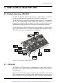
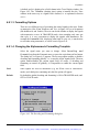
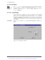
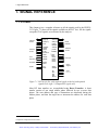
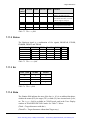
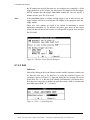
1
Artisan Technology Group is your source for quality new and certified-used/pre-owned equipment • FAST SHIPPING AND DELIVERY • TENS OF THOUSANDS OF IN-STOCK ITEMS • EQUIPMENT DEMOS • HUNDREDS OF MANUFACTURERS SUPPORTED • LEASING/MONTHLY RENTALS • ITAR CERTIFIED SECURE ASSET SOLUTIONS SERVICE CENTER REPAIRS Experienced engineers and technicians on staff at our full-service, in-house repair center WE BUY USED EQUIPMENT Sell your excess, underutilized, and idle used equipment We also offer credit for buy-backs and trade-ins www.artisantg.com/WeBuyEquipment InstraView REMOTE INSPECTION LOOKING FOR MORE INFORMATION? Visit us on the web at www.artisantg.com for more information on price quotations, drivers, technical specifications, manuals, and documentation SM Remotely inspect equipment before purchasing with our interactive website at www.instraview.com Contact us: (888) 88-SOURCE | [email protected] | www.artisantg.com User's Manual PBT(X)-515 - PCI Bus Analyzer & Exerciser Including PXMEM8M-PB Version 3.02, valid for Firmware 6.0x / BusView 3.0x Copyright VMETRO 2000. No part of this document may be furnished or disclosed to any third party, and it may not be copied or reproduced in any form, electronic, mechanical, or otherwise, without written permission from VMETRO Inc. (Houston, TX, USA) or VMETRO asa (Oslo, Norway). The Bus Analyzer Specialist Artisan Technology Group - Quality Instrumentation ... Guaranteed | (888) 88-SOURCE | www.artisantg.com Warranty VMETRO products are warranted against defective materials and workmanship within the warranty period of 1 (one) year from date of invoice. Within the warranty period, VMETRO will, free of charge, repair or replace any defective unit covered by this warranty, shipping prepaid. A Return Authorization Code should be obtained from VMETRO prior to return of any defective product. With any returned product, a written description of the nature of malfunction should be enclosed. The product must be shipped in its original shipping container or similar packaging with sufficient mechanical and electrical protection in order to maintain warranty. This warranty assumes normal use. Products subjected to unreasonably rough handling, negligence, abnormal voltages, abrasion, unauthorized parts replacement and repairs, or theft are not covered by this warranty and will if possible be repaired for time and material charges in effect at the time of repair. VMETRO's warranty is limited to the repair or replacement policy described above and neither VMETRO nor its agent shall be responsible for consequential or special damages related to the use of their products. Limited Liability VMETRO does not assume any liability arising out of the application or use of any product described herein; neither does it convey any license under its patent rights nor the rights of others. VMETRO products are not designed, intended, or authorized for use as components in systems intended to support or sustain life, or for any application in which failure of the VMETRO product could create a situation where personal injury or death may occur. Should Buyer purchase or use VMETRO products for any such unintended or unauthorized application, Buyer shall indemnify and hold VMETRO and its officers, employees, subsidiaries, affiliates, and distributors harmless against all claims, costs, damages, and expenses, and reasonable attorney fees arising out of, directly or indirectly, any claim of personal injury or death associated with such unintended or unauthorized use, even if such claim alleges that VMETRO was negligent regarding the design or manufacture of the part. ii User's Manual PBT-515 PCI Bus Analyzer & Exerciser Artisan Technology Group - Quality Instrumentation ... Guaranteed | (888) 88-SOURCE | www.artisantg.com USA: VMETRO, Inc. 1880 Dairy Ashford, Suite 535 HOUSTON, TX 77077, USA Tel: (281) 584-0728 Fax: (281) 584-9034 Email: [email protected] Europe, Asia: VMETRO asa Brynsveien 5 0667 OSLO, Norway Tel: +47 22 10 60 90 Fax: +47 22 10 62 02 Email: [email protected] http://www.vmetro.com User's Manual PBT-515 PCI Bus Analyzer & Exerciser Artisan Technology Group - Quality Instrumentation ... Guaranteed | (888) 88-SOURCE | www.artisantg.com iii The Bus Analyzer concept A Bus Analyzer is a pre-configured logic analyzer designed as a plug-in card for a specific bus, conforming to the logical, electrical and mechanical specification of the target bus. The primary use of a Bus Analyzer is to monitor the activity on a back plane bus and provide a trace of bus cycles between modules on the bus, presenting this as alphanumeric trace lists or as wave forms on a PC or an ASCII terminal. This is done without connecting and configuring large numbers of probes to the back plane, a time-consuming and error-prone process necessary with general-purpose logic analyzers. Statistics analysis in bus systems are also an important application for bus analyzers. The basic idea behind bus analyzers is that the analyzer is "hard-wired" to capture the protocol of the target bus, thereby reducing the need for the user to understand all the details of the bus protocol in order to perform meaningful analysis of activity in the target system. This offers the user maximum productivity and convenience during development, debugging, testing and verification of bus based computer systems. VMETRO is a company totally committed to building the finest Bus Analyzers, and is recognized in development labs around the world as providing superior tools for developers and manufacturers of bus based computer equipment. VMETRO has been building bus analyzers for more than 14 years, resulting in four generations of VME Bus Analyzers, and now the third generation of PCI bus analyzers, the PBT-515 PCI Bus Analyzer and Exerciser, the PBTM-515 PMC Analyzer, and the PBTC-415 CompactPCI Bus Analyzer and Exerciser. The Bus Analyzer Specialist iv User's Manual PBT-515 PCI Bus Analyzer & Exerciser Artisan Technology Group - Quality Instrumentation ... Guaranteed | (888) 88-SOURCE | www.artisantg.com User's Manual PBT-515 PCI Bus Analyzer & Exerciser Artisan Technology Group - Quality Instrumentation ... Guaranteed | (888) 88-SOURCE | www.artisantg.com v CONTENTS CONTENTS 1. GETTING STARTED.............................................................................. 1 1.1 Introduction....................................................................................................................1 1.1.1 Expandable with Piggyback Modules ...................................................................1 1.2 Getting Started ...............................................................................................................2 1.2.1 Getting Started Using a Terminal User Interface...................................................7 2. INSTALLATION.................................................................................... 11 2.1 Static Electricity - Precautions ....................................................................................11 2.2 Preparations PBT-515, PCI Bus Analyzer and Exerciser .......................................11 2.2.1 Inspection ............................................................................................................11 2.2.2 Slot Selection.......................................................................................................12 2.2.3 Power Consumption............................................................................................12 2.3 Preparations PBTM-515, PMC Analyzer .................................................................13 2.3.1 Inspection ............................................................................................................13 2.3.2 Power Consumption............................................................................................14 2.3.3 Top Spacer for Stacking......................................................................................15 2.3.3.1 Installing the Top Spacer ............................................................................15 2.3.4 90° PMC Test-Adapter .......................................................................................16 2.3.4.1 Installing the 90° PMC Test-Adapter..........................................................16 2.4 BusView for Windows - Graphical User Interface ...................................................17 2.4.1 System Requirements ..........................................................................................17 2.4.2 Installing BusView on the PC .............................................................................17 2.4.3 RS-232 or USB...................................................................................................17 2.4.4 Establish communication - USB..........................................................................18 2.4.5 Establish communication - RS-232 .....................................................................18 2.4.5.1 Communication Parameters ........................................................................19 2.4.6 Troubleshooting: Connection Problems ..............................................................20 2.4.6.1 Troubleshooting Checklist ..........................................................................21 2.5 Terminal User Interface ..............................................................................................21 2.5.1 Establish a Connection ........................................................................................21 vi User's Manual PBT-515 PCI Bus Analyzer & Exerciser Artisan Technology Group - Quality Instrumentation ... Guaranteed | (888) 88-SOURCE | www.artisantg.com CONTENTS 2.5.2 Start-up Menu......................................................................................................22 2.5.2.1 Select New Terminal Type .........................................................................22 2.5.2.2 Clear Non-Volatile Memory .......................................................................23 2.6 Accessories....................................................................................................................24 3. FUNCTIONAL DESCRIPTION ..........................................................25 3.1 Product Overview - PBT-515......................................................................................25 3.1.1 PBTM-515 ..........................................................................................................25 3.2 Models...........................................................................................................................26 3.3 PCI Analyzer Features................................................................................................26 3.3.1 De-multiplexed Address/Data .............................................................................27 3.3.2 Address Incrementing..........................................................................................27 3.3.3 Data Presentation.................................................................................................27 3.4 PCI Exerciser Features ...............................................................................................28 3.4.1 Reference Unit ....................................................................................................28 3.4.2 Simultaneous Master and PCI Analysis...............................................................29 3.4.3 Script Function Allows Automated Testing ........................................................29 3.4.4 Emulate a Board under Design............................................................................29 3.4.5 DMA Transfers ...................................................................................................29 3.4.6 Target Memory....................................................................................................29 3.4.7 Generate PCI Interrupts.......................................................................................30 3.4.8 Scan PCI Config Space.......................................................................................30 3.5 Sampling Modes...........................................................................................................30 3.5.1 CLOCK Sampling ..............................................................................................31 3.5.2 TRANSFER Sampling .......................................................................................31 3.5.2.1 TRANSFER DETAILS Sampling.............................................................32 3.5.3 TRANSACTION Sampling ...............................................................................32 3.6 Main Blocks - Analyzer ...............................................................................................32 3.6.1 Sampling Stage....................................................................................................33 3.6.1.1 External Inputs............................................................................................34 3.6.1.2 GNT# Latching ..........................................................................................35 3.6.1.3 Shared Signals - PBT-515 ..........................................................................36 3.6.1.4 Shared Signals - PBTM-515.......................................................................36 3.6.2 Word Recognition / Triggering Stage..................................................................36 User's Manual PBT-515 PCI Bus Analyzer & Exerciser vii Artisan Technology Group - Quality Instrumentation ... Guaranteed | (888) 88-SOURCE | www.artisantg.com CONTENTS 3.6.3 Sequencer............................................................................................................37 3.6.4 Sample Storage Stage..........................................................................................38 3.6.4.1 Trace Buffer................................................................................................38 3.6.4.2 Trigger Position ..........................................................................................38 3.6.5 Investigating System Performance - Statistics Functions .....................................39 3.6.6 64-bits Support ....................................................................................................39 4. OPERATION........................................................................................... 40 4.1 Window Elements and Commands ............................................................................40 4.2 Using BusView .............................................................................................................41 4.2.1 Mouse Control.....................................................................................................41 4.2.2 Keyboard Control................................................................................................41 4.3 Multiple BusView Sessions..........................................................................................42 4.4 User-Interface Structure .............................................................................................43 4.4.1 Setup Window.....................................................................................................43 4.4.2 Trace Display Window .......................................................................................45 4.4.3 Statistics Window................................................................................................45 4.4.4 Exerciser Window...............................................................................................46 4.4.4.1 Prompt Based Command Editing................................................................47 4.4.4.2 PCI Commands - Exerciser Examples ........................................................49 4.4.5 Bus Utilization Meter window ............................................................................50 4.5 Event Patterns..............................................................................................................52 4.5.1 Editing Event Patterns .........................................................................................53 4.5.1.1 Edit Fields...................................................................................................53 4.5.1.2 Field Options ..............................................................................................54 4.5.1.3 Clearing Contents of Signal Fields..............................................................55 4.5.1.4 Hiding Signal Field Columns......................................................................55 4.5.1.5 Adding Signal Field Columns.....................................................................55 4.5.1.6 Renaming, Deleting, Adding and Copying Entire Events ..........................56 4.5.2 Address/Data Options .........................................................................................57 4.5.3 Different Signal Templates..................................................................................59 4.6 Single Event Mode .......................................................................................................60 4.6.1.1 Editing the Single Event .............................................................................60 4.7 Sequencer Mode...........................................................................................................61 viii User's Manual PBT-515 PCI Bus Analyzer & Exerciser Artisan Technology Group - Quality Instrumentation ... Guaranteed | (888) 88-SOURCE | www.artisantg.com CONTENTS 4.7.1 Tutorial................................................................................................................61 4.7.2 Sequencer - a State Machine ...............................................................................68 4.7.3 Open Sequencer ..................................................................................................68 4.7.3.1 Return to Single Event Mode......................................................................69 4.7.4 Edit Sequencer ....................................................................................................69 4.7.5 Sequencer Reference...........................................................................................71 4.7.5.1 General Structure of a State ........................................................................71 4.7.5.2 Sequencer Notation.....................................................................................73 4.7.5.3 Operators ....................................................................................................75 4.7.5.4 Implicit Actions/Transitions ........................................................................78 4.7.5.5 Edit Event Expressions ...............................................................................78 4.7.6 Sequencer Programming Examples.....................................................................79 4.7.6.1 Loose and Tight Sequences ........................................................................79 4.7.6.2 Count, Delay and Switch Sampling mode ..................................................80 4.7.6.3 Trigger on Address Range and Data...........................................................80 4.8 Trace Display ...............................................................................................................81 4.8.1 Alphanumeric Trace List.....................................................................................81 4.8.1.1 Navigation and Signal Selection .................................................................82 4.8.1.2 Absolute or Relative Time in the Trace Window........................................82 4.8.1.3 Formatting Options .....................................................................................83 4.8.1.4 Changing the Alphanumeric Formatting Template .....................................83 4.8.1.5 Navigating the Trace Buffer in Alphanumeric Mode..................................84 4.8.1.6 Trace Compare ...........................................................................................85 4.8.2 Waveforms ..........................................................................................................87 4.8.2.1 Navigating the Trace Buffer in Waveform Mode .......................................87 4.8.2.2 Setting Markers...........................................................................................88 4.8.3 Additional Windows ...........................................................................................89 4.8.4 Trace Dump to PC/Host......................................................................................90 4.9 Statistics ........................................................................................................................91 4.9.1.1 Counter Driven ...........................................................................................91 4.9.1.2 Trace Driven...............................................................................................91 4.9.2 Event Counting ...................................................................................................92 4.9.3 Bus Utilization.....................................................................................................93 4.9.3.1 Bus Utilization Meter..................................................................................94 User's Manual PBT-515 PCI Bus Analyzer & Exerciser Artisan Technology Group - Quality Instrumentation ... Guaranteed | (888) 88-SOURCE | www.artisantg.com ix CONTENTS 4.9.4 Bus Transfer Rate................................................................................................95 4.9.5 Bus Profile...........................................................................................................95 4.9.6 Burst Distribution ................................................................................................96 4.9.7 Command Distribution ........................................................................................97 4.9.8 Statistics Options .................................................................................................98 4.9.8.1 Statistics Window .......................................................................................98 4.9.8.2 Histograms or Time History Curves ...........................................................99 4.9.8.3 Bar Markers ..............................................................................................100 4.9.8.4 Count Options...........................................................................................101 5. PXMEM8M-PB EXTENDED MEMORY .......................................104 5.1 PXMEM8M-PB Extended Memory ........................................................................104 5.2 Triggering...................................................................................................................104 5.3 External Inputs ..........................................................................................................105 5.4 Trace Decode..............................................................................................................105 6. COMMANDS REFERENCE..............................................................108 6.1 File Menu....................................................................................................................108 6.1.1 New Setup.........................................................................................................108 6.1.2 Load Predefined Setup ......................................................................................108 6.1.3 Open..................................................................................................................109 6.1.4 Save, Save as.....................................................................................................109 6.1.5 Print...................................................................................................................109 6.1.6 Printer Setup......................................................................................................110 6.1.7 Save Settings on Exit.........................................................................................110 6.1.8 Exit....................................................................................................................110 6.2 Edit Menu...................................................................................................................110 6.2.1 Undo .................................................................................................................111 6.2.2 Cut.....................................................................................................................111 6.2.3 Copy..................................................................................................................111 6.2.4 Paste ..................................................................................................................111 6.2.5 Clear..................................................................................................................111 6.2.6 Insert..................................................................................................................112 6.2.7 Open Sequencer ................................................................................................112 x User's Manual PBT-515 PCI Bus Analyzer & Exerciser Artisan Technology Group - Quality Instrumentation ... Guaranteed | (888) 88-SOURCE | www.artisantg.com CONTENTS 6.2.8 Trigger Position.................................................................................................112 6.2.9 Sampling Mode .................................................................................................112 6.2.9.1 Sampling Options .....................................................................................113 6.3 Compare Menu ..........................................................................................................114 6.3.1 Trace Compare..................................................................................................114 6.3.2 Trace Compare Options ....................................................................................114 6.3.3 Jump Next Error................................................................................................114 6.3.4 Jump Previous Error..........................................................................................114 6.4 Trace Menu ................................................................................................................114 6.4.1 Run PCI ............................................................................................................115 6.4.2 Run Multiple .....................................................................................................115 6.4.3 Halt....................................................................................................................115 6.4.4 Halt All..............................................................................................................115 6.4.5 Show PCI..........................................................................................................115 6.4.6 Sampling Status.................................................................................................115 6.5 Setups Menu...............................................................................................................116 6.5.1 Initialize.............................................................................................................116 6.5.2 Load ..................................................................................................................116 6.5.3 Store ..................................................................................................................117 6.5.4 Delete ................................................................................................................117 6.5.5 Make Current ....................................................................................................117 6.6 Utilities Menu .............................................................................................................117 6.6.1 Communication .................................................................................................117 6.6.1.1 Connect.....................................................................................................118 6.6.1.2 Disconnect ................................................................................................118 6.6.1.3 Port Settings..............................................................................................118 6.6.2 Update Tracer Firmware ...................................................................................118 6.6.3 Clear Non-Volatile Memory..............................................................................118 6.6.4 Trigger Output Options .....................................................................................118 6.6.5 Simulated Hardware..........................................................................................119 6.6.6 User Interface Options.......................................................................................119 6.6.7 Bus Utilization Meter ........................................................................................120 6.6.8 Bus Utilization Meter Options...........................................................................120 6.6.9 Selftest...............................................................................................................120 User's Manual PBT-515 PCI Bus Analyzer & Exerciser Artisan Technology Group - Quality Instrumentation ... Guaranteed | (888) 88-SOURCE | www.artisantg.com xi CONTENTS 6.6.10 Reset Analyzer ................................................................................................120 6.6.11 Reset Exerciser................................................................................................121 6.6.12 Specials ...........................................................................................................121 6.7 Window Menu............................................................................................................121 6.7.1 Cascade .............................................................................................................121 6.7.2 Tile Horizontally ...............................................................................................121 6.7.3 Tile Vertically....................................................................................................121 6.7.4 Arrange Icons....................................................................................................121 6.7.5 Alphanumeric List.............................................................................................122 6.7.6 Waveform..........................................................................................................122 6.7.7 Select Window ..................................................................................................122 6.8 Help Menu ..................................................................................................................122 6.8.1 Contents ............................................................................................................122 6.8.2 Search for Help on ............................................................................................123 6.8.3 Using Help ........................................................................................................123 6.9 Trace Display .............................................................................................................123 6.9.1 Search menu......................................................................................................123 6.9.1.1 Edit Search Pattern....................................................................................123 6.9.1.2 Extract.......................................................................................................124 6.9.1.3 Search .......................................................................................................124 6.9.1.4 Next Match ...............................................................................................124 6.9.1.5 Previous Match .........................................................................................124 6.9.1.6 Previous Edge...........................................................................................124 6.9.1.7 Next Edge.................................................................................................124 6.9.1.8 Edge Options ............................................................................................125 6.9.2 Jump Menu........................................................................................................125 6.9.2.1 First Line...................................................................................................125 6.9.2.2 Last Line...................................................................................................125 6.9.2.3 Trigger Line..............................................................................................125 6.9.2.4 Marker Y ..................................................................................................125 6.9.2.5 Marker Z...................................................................................................125 6.9.2.6 Line Number.............................................................................................126 6.9.3 Count.................................................................................................................126 6.9.4 Format Menu.....................................................................................................127 xii User's Manual PBT-515 PCI Bus Analyzer & Exerciser Artisan Technology Group - Quality Instrumentation ... Guaranteed | (888) 88-SOURCE | www.artisantg.com CONTENTS 6.9.4.1 Scale .........................................................................................................127 6.9.4.2 Zoom In ....................................................................................................127 6.9.4.3 Zoom Out .................................................................................................127 6.9.4.4 Decoding and Formatting .........................................................................127 6.9.4.5 Trace Signal..............................................................................................128 6.9.5 Marker Menu.....................................................................................................128 6.9.5.1 Set Marker Y ............................................................................................128 6.9.5.2 Set Marker Z.............................................................................................128 6.9.5.3 Delete Marker Y .......................................................................................128 6.9.5.4 Delete Marker Z........................................................................................128 6.10 Statistics ....................................................................................................................128 6.10.1 Session Menu ..................................................................................................128 6.10.1.1 Run .........................................................................................................129 6.10.1.2 Continue .................................................................................................129 6.10.1.3 Halt .........................................................................................................129 6.10.1.4 Immediate Start .......................................................................................129 6.10.1.5 Start On Trigger......................................................................................129 6.10.2 Function Menu ................................................................................................129 6.10.2.1 Event Counting.......................................................................................129 6.10.2.2 Bus Utilization ........................................................................................130 6.10.2.3 Bus Transfer Rate ...................................................................................130 6.10.2.4 Bus Profile ..............................................................................................130 6.10.3 Burst Distribution ............................................................................................130 6.10.4 Command Distribution ....................................................................................130 6.10.5 Options............................................................................................................130 6.10.5.1 Histograms..............................................................................................131 6.10.5.2 Time History Curves...............................................................................131 6.10.5.3 Bar Markers ............................................................................................131 6.10.5.4 Graph Display Options ...........................................................................131 6.10.5.5 Unit.........................................................................................................132 6.10.5.6 Maximum Scale ......................................................................................132 6.10.5.7 Count Options.........................................................................................132 6.10.5.8 Select Events...........................................................................................133 6.10.5.9 Sampling Mode.......................................................................................133 User's Manual PBT-515 PCI Bus Analyzer & Exerciser xiii Artisan Technology Group - Quality Instrumentation ... Guaranteed | (888) 88-SOURCE | www.artisantg.com CONTENTS 6.10.5.10 Save Statistics to File ............................................................................133 6.11 Exerciser ...................................................................................................................135 6.11.1 Introduction .....................................................................................................135 6.11.2 Help.................................................................................................................135 6.11.3 Master Menu ...................................................................................................136 6.11.3.1 Display....................................................................................................136 6.11.3.2 Modify ....................................................................................................138 6.11.3.3 Write .......................................................................................................140 6.11.3.4 Fill...........................................................................................................142 6.11.3.5 DMA ......................................................................................................144 6.11.3.6 TDMA....................................................................................................147 6.11.3.7 DMA Abort ............................................................................................149 6.11.3.8 Test .........................................................................................................150 6.11.3.9 Compare .................................................................................................152 6.11.3.10 Cycle Sequence ....................................................................................154 6.11.3.11 Exercise ................................................................................................156 6.11.3.12 Interrupt Acknowledge .........................................................................158 6.11.3.13 Special Cycle ........................................................................................159 6.11.3.14 Config Scan ..........................................................................................160 6.11.4 Local Menu .....................................................................................................162 6.11.4.1 Local Display..........................................................................................162 6.11.4.2 Local Modify ..........................................................................................164 6.11.4.3 Local Fill.................................................................................................165 6.11.5 Load - Save Commands ..................................................................................167 6.11.5.1 Save Memory to File...............................................................................167 6.11.5.2 Save Local Memory to File.....................................................................168 6.11.5.3 Load Memory from File..........................................................................169 6.11.5.4 Load Local Memory from File................................................................170 6.11.6 Script Menu.....................................................................................................171 6.11.6.1 Load........................................................................................................171 6.11.6.2 Run .........................................................................................................171 6.11.6.3 Run Loop................................................................................................172 6.11.6.4 Stop.........................................................................................................172 6.11.6.5 Show.......................................................................................................172 xiv User's Manual PBT-515 PCI Bus Analyzer & Exerciser Artisan Technology Group - Quality Instrumentation ... Guaranteed | (888) 88-SOURCE | www.artisantg.com CONTENTS 6.11.6.6 Start Recording .......................................................................................172 6.11.6.7 Insert Pause.............................................................................................173 6.11.6.8 Insert Comment.......................................................................................173 6.11.6.9 Insert Wait...............................................................................................173 6.11.6.10 Insert Loop............................................................................................173 6.11.6.11 Insert End of Loop................................................................................173 6.11.6.12 Stop Recording .....................................................................................173 6.11.6.13 Silent Mode...........................................................................................174 6.11.7 Miscellaneous Commands...............................................................................174 6.11.7.1 Target......................................................................................................174 6.11.7.2 Interrupt ..................................................................................................176 6.11.7.3 Options ...................................................................................................178 6.11.7.4 Version ...................................................................................................180 6.11.8 Commands only available in Terminal mode ..................................................180 6.11.8.1 Speed ......................................................................................................180 6.11.9 File Menu ........................................................................................................181 6.11.9.1 Save ........................................................................................................181 6.11.9.2 Load........................................................................................................181 6.11.9.3 Print ........................................................................................................181 7. SIGNAL REFERENCE .......................................................................184 7.1 PCI Bus.......................................................................................................................184 7.2 PCI Transfer ..............................................................................................................185 7.3 System Pins.................................................................................................................185 7.4 Address and Data Pins ..............................................................................................185 7.4.1 Bus Command Field..........................................................................................186 7.5 Interface Control Pins ...............................................................................................186 7.6 Arbitration Pins .........................................................................................................187 7.7 Error Reporting Pins.................................................................................................187 7.8 Interrupt Pins.............................................................................................................187 7.9 Cache Support Pins ...................................................................................................187 7.10 64-bits Bus Extension Pins ......................................................................................188 7.11 Signal Groups...........................................................................................................188 7.11.1 Size..................................................................................................................188 User's Manual PBT-515 PCI Bus Analyzer & Exerciser xv Artisan Technology Group - Quality Instrumentation ... Guaranteed | (888) 88-SOURCE | www.artisantg.com CONTENTS 7.11.2 Status...............................................................................................................189 7.11.3 Err ...................................................................................................................189 7.11.4 State.................................................................................................................189 7.11.5 Burst/Burst# ....................................................................................................190 7.11.6 Wait.................................................................................................................191 8. TERMINAL USER INTERFACE .....................................................192 8.1 Using a Terminal Instead of BusView......................................................................192 8.1.1 Keyboard Control..............................................................................................192 8.1.1.1 Keyboard Control Within Dialog Boxes...................................................192 8.1.2 Screen Categories..............................................................................................193 8.1.3 Setup Screen......................................................................................................193 8.1.3.1 Trace.........................................................................................................193 8.1.3.2 Edit ...........................................................................................................194 8.1.3.3 Edit Event Patterns....................................................................................195 8.1.3.4 Edit the Sequencer, Single Event Mode....................................................197 8.1.3.5 Edit the Sequencer, Sequencer Mode .......................................................198 8.1.3.6 Utilities......................................................................................................198 8.1.3.7 Setups .......................................................................................................199 8.1.4 Trace Display Screen ........................................................................................202 8.1.4.2 Trace.........................................................................................................202 8.1.4.3 Jump .........................................................................................................203 8.1.4.4 Format.......................................................................................................203 8.1.4.5 Statistics Screen ........................................................................................204 8.1.4.6 Exerciser Screen .......................................................................................205 8.2 VMETRO VT100 Terminal Emulator ....................................................................205 8.2.1 Starting the VT100............................................................................................206 8.2.1.1 Options .....................................................................................................207 8.2.2 VT100 Environment Variable...........................................................................207 8.2.3 Terminal Types to Use on theTracer .................................................................207 8.2.3.1 Built-in XMODEM CRC Protocol...........................................................207 8.2.4 Built-in Script Language ...................................................................................208 8.2.4.1 Script Control Commands.........................................................................208 8.2.4.2 Function Keys in Script Files....................................................................209 xvi User's Manual PBT-515 PCI Bus Analyzer & Exerciser Artisan Technology Group - Quality Instrumentation ... Guaranteed | (888) 88-SOURCE | www.artisantg.com CONTENTS 8.2.4.3 Script Example #1.....................................................................................210 8.2.4.4 Script Example #2.....................................................................................211 9. TRACE FILE FORMAT .....................................................................212 9.1 Trace File Format ......................................................................................................212 9.2 Trace Data Line format.............................................................................................215 9.3 Details of the Time Tag Variables ............................................................................216 9.4 Converting the Time Tag to a Time Value ..............................................................216 9.5 Details of Internally Generated Bits .........................................................................218 9.6 BusView Trace File Format......................................................................................218 10. FIRMWARE UPGRADE ..................................................................224 10.1 Firmware Upgrade Preparations ...........................................................................224 10.1.1 Firmware CD ..................................................................................................224 10.1.2 Boot PROM ....................................................................................................224 10.1.3 RS232 Connection ..........................................................................................224 10.1.4 Power on the FLASH EPROMs.....................................................................224 10.2 Firmware Upgrade Using BusView .......................................................................224 10.3 Firmware Upgrade Using MS-DOS.......................................................................226 10.3.1 Uploading Tracer Firmware ............................................................................227 10.3.2 Uploading Exerciser Firmware........................................................................229 10.4 Troubleshooting - Firmware Upgrade...................................................................229 10.4.1 If Upload Stops ...............................................................................................229 10.4.2 Communication Errors ....................................................................................230 10.4.3 Flash Memory Errors.......................................................................................230 10.4.4 Tuning Parameters Lost...................................................................................230 10.4.4.1 Missing PCB and ECO Level.................................................................231 11. JUMPER SETTINGS ........................................................................234 11.1 PBT-515....................................................................................................................234 11.2 PBTM-515 ................................................................................................................234 11.3 Jumper Details .........................................................................................................235 11.3.1 UART Jumper Settings ...................................................................................235 11.3.2 PowerPC Flash EPROM Jumper Settings.......................................................235 User's Manual PBT-515 PCI Bus Analyzer & Exerciser xvii Artisan Technology Group - Quality Instrumentation ... Guaranteed | (888) 88-SOURCE | www.artisantg.com CONTENTS 12. APPENDIX A ......................................................................................237 12.1 List of figures............................................................................................................237 12.2 List of tables..............................................................................................................242 13. INDEX...................................................................................................245 xviii User's Manual PBT-515 PCI Bus Analyzer & Exerciser Artisan Technology Group - Quality Instrumentation ... Guaranteed | (888) 88-SOURCE | www.artisantg.com CONTENTS User's Manual PBT-515 PCI Bus Analyzer & Exerciser xix Artisan Technology Group - Quality Instrumentation ... Guaranteed | (888) 88-SOURCE | www.artisantg.com Artisan Technology Group - Quality Instrumentation ... Guaranteed | (888) 88-SOURCE | www.artisantg.com 1 Getting Started 1. GETTING STARTED 1.1 Introduction Throughout this manual the term PBT(X)-515 will be used when the issue discussed applies to both the PBT-515 and the PBTM-515. The main function of the PBT(X)-515 is to collect samples of the PCI bus activity into a circular trace buffer, and at the same time compare the samples with a userdefined trigger pattern, so that the acquisition process stops at, or around, a moment of interest. The PBT-515 also includes an onboard PCI Exerciser unit that allows the user to generate PCI traffic, emulate a PCI target, and generate PCI interrupts. 1.1.1 Expandable with Piggyback Modules Although the PBT-515 offers a full-featured logic state analyzer with extensive statistics functions as well as a powerful exerciser, the unit can be expanded with piggyback modules (daughtercards) for even more functionality and performance. One such card is the PTIMBAT500-PB, targeted at detailed hardware analysis applications. This module offers a 64-channel 500 MHz Timing Analyzer with 16 MSamples trace buffer, and a comprehensive PCI Anomaly Trigger (protocol checker). In addition to offering a detailed 2ns resolution view with waveform diagrams of the bus timing, this unit provides automatic detection of 84 PCI protocol and timing violations, including 50 picoseconds timing resolution on setup/hold time measurements. Another card, the PXMEM8M-PB, offers an extremely deep trace buffer for the state analyzer, storing as much as 8 million clock, address or data cycles, suitable for statistics gathering or verification applications. (Only one piggyback module can be mounted at a time.) User's Manual PBT-515 PCI Bus Analyzer & Exerciser Artisan Technology Group - Quality Instrumentation ... Guaranteed | (888) 88-SOURCE | www.artisantg.com 1 1 Getting Started PTIMBAT500 -PB (Optional) 500 MHz Timing Analyzer 4 Ext. Trig PXMEM8M-PB (Optional) Anomaly Trigger 8M Samples State Analyzer (Protocol & Timing Checker) (16M) 64-bit/66MHz 64-bit/33MHz Trig Trig PBT-515 8 Ext. Trig State Analyzer Exerciser (64K/256K) (Master & Target) USB RS232 64-bit/66MHz 64-bit/66MHz PCI Figure 1.1 The PBT-515 with piggyback modules 1.2 Getting Started BusView is the graphical user interface for the PBT(X)-515, offering a userfriendly mouse operation of the PBT(X)-515 PCI Bus Analyzer and Exerciser system. The following steps must be carried out before BusView is ready to run: • Install the PBT-515 according to Section 2.2, or the PBTM-515 according to Section 2.3. • Install BusView according to the description in Section 2.4.2. • Connect a cable, USB or RS-232, between the PBT(X)-515 and the PC, see Section 2.4.4 and Section 2.4.5. • Set the communication parameters, and connect the PBT(X)-515 as described in Section 2.4.5.1. If everything is installed correctly, BusView should now display the Setup window shown in Figure 1.2. The Setup window is divided in two, the Event Patterns window, and the Sequencer window. For further information about the Setup Window, read Section 4.4.1. 2 User's Manual PBT-515 PCI Bus Analyzer & Exerciser Artisan Technology Group - Quality Instrumentation ... Guaranteed | (888) 88-SOURCE | www.artisantg.com 1 Getting Started TRANSFER mode TRANSACTION mode Trace Run CLOCK mode Event Patterns Window Sequencer Window Figure 1.2 The Setup window, where triggers, sampling modes etc., is defined TRANSFER Mode The PBT(X)-515 has three main sampling modes, CLOCK, TRANSFER (default), and TRANSACTION mode. In addition there is a fourth sampling mode which is a combination of the CLOCK and the TRANSFER sampling modes. Section 3.5 includes a detailed description of the sampling modes. Trace/Run Select Trace/Run from the menu bar, (or click on the “lightning” button at the tool bar), to get a sample of the current bus activity. After a few moments, the Trace window is displayed (assuming there is traffic on the PCI bus), see Figure 1.3. The contents of the Trace window is now a snapshot of the current bus traffic. User's Manual PBT-515 PCI Bus Analyzer & Exerciser Artisan Technology Group - Quality Instrumentation ... Guaranteed | (888) 88-SOURCE | www.artisantg.com 3 1 Getting Started Figure 1.3 The Trace Display window (TRANSFER mode sampling) Ctrl-Tab Switch back to the Setup window by pressing the Ctrl-key together with the Tab-key, or by using the mouse. Operating BusView is described in Section 4.2. CLOCK Mode Change sampling mode to CLOCK mode by selecting Edit/Sampling mode/Clock from the menu bar, or by pressing the CLOCK tool bar button. Notice that the first line in the Sequencer window now displays “Sampling in CLOCK mode”. Trace/Run Select Trace/Run once more. The Trace window opens again. By pressing the tool bar button showing a waveform display, or by selecting waveform from the Window menu, the waveform version of the Trace Display window appears. The waveform window is shown in Figure 1.4. To avoid sampling while the PCI bus is idle, it is necessary to set up a trigger condition. Click on FRAME# in the Event Patterns window on the PCI0 line and type a 0 (zero). This will ensure that a PCI cycle is captured. 4 User's Manual PBT-515 PCI Bus Analyzer & Exerciser Artisan Technology Group - Quality Instrumentation ... Guaranteed | (888) 88-SOURCE | www.artisantg.com 1 Getting Started Figure 1.4 The waveform window TRANSACTION Mode Trace/Run Change sampling mode to TRANSACTION mode by selecting Edit/Sampling mode/Transaction from the menu bar, or by pressing the TRANSACTION tool bar button. Notice that the first line in the Sequencer window now displays “Sampling in TRANSACTION (NO DATA) mode”. Select Trace/Run once more. The Trace window opens again. Note that a filed called BurstLen has replaced the Data field in the trace. User's Manual PBT-515 PCI Bus Analyzer & Exerciser Artisan Technology Group - Quality Instrumentation ... Guaranteed | (888) 88-SOURCE | www.artisantg.com 5 1 Getting Started Figure 1.5 The Trace Display window when sampling in TRANSACTION mode Continue reading Chapter 4 for a detailed description about how to use the PBT515. The "Exerciser" tool bar button 6 By selecting Exerciser from the menu bar, or pressing the corresponding button at the tool bar (see Section 6.11.1), the PCI Exerciser window is opened. User's Manual PBT-515 PCI Bus Analyzer & Exerciser Artisan Technology Group - Quality Instrumentation ... Guaranteed | (888) 88-SOURCE | www.artisantg.com 1 Getting Started Figure 1.6 The Exerciser window The Exerciser can be operated from the menu bar, the tool bar, or by typing commands at the Exerciser prompt in the Exerciser window. In Figure 1.6, the Exerciser is doing a display of the local user memory. See Section 6.11 for a description of how to use the PCI Exerciser. 1.2.1 Getting Started Using a Terminal User Interface The PBT(X)-515 can also be operated from an ASCII terminal, such as the VT100 or compatible. The following steps have to be carried out before the terminal is ready to run: • Install the PBT-515 according to Section 2.2, or the PBTM-515 according to Section 2.3. • Follow the instructions in Section 2.5 for establishing a connection between the terminal and the PBT(X)-515. If everything proceeded correctly the terminal should now display the setup screen shown in Figure 1.7. The Setup screen is divided in two, the Event Patterns window, and the Sequencer window. For further information about the Setup screen, read Section 4.4.1 and Section 8.1.3. Sampling The PBT(X)-515 has three main sampling modes, CLOCK, TRANSFER (default), and TRANSACTION mode. In addition there is a fourth sampling mode which is a mixture of the CLOCK and TRANSFER sampling modes. Section 3.5 includes a detailed description of the sampling modes. User's Manual PBT-515 PCI Bus Analyzer & Exerciser Artisan Technology Group - Quality Instrumentation ... Guaranteed | (888) 88-SOURCE | www.artisantg.com 7 1 Getting Started Trace/Run Type <T> and <R> to execute the command Trace/Run. The Trace window displays a snap shot of the current bus activity, see Figure 1.8. The contents of the Trace Display window depends on the current bus traffic. Quit Type <Q> to quit the Trace Display screen and return to the Setup screen. CLOCK mode Change sampling mode to CLOCK mode by selecting Edit/Sampling Mode/Clock from the menu bar. Notice that the first line in the Sequencer window now displays “Sampling in CLOCK mode”. Figure 1.7 The Setup screen, terminal view Trace/Run 8 Type <T> and <R> to execute the command Trace/Run once more.The Trace window opens again. By selecting waveform from the Window menu, the waveform version of the Trace Display window appears. The waveform window is shown in Figure 1.9. To avoid sampling while the PCI bus is idle, it is necessary to set up a trigger condition. Type <i> (Edit) and <e> (Event) to enable editing in the Event Patterns window. With the cursor keys, select the FRAME# field in the PCI0 line, and type a 0. This will ensure that a PCI cycle is captured. User's Manual PBT-515 PCI Bus Analyzer & Exerciser Artisan Technology Group - Quality Instrumentation ... Guaranteed | (888) 88-SOURCE | www.artisantg.com 1 Getting Started Figure 1.8 The Alphanumeric Trace Display screen (CLOCK mode sampling) Figure 1.9 The Waveform Trace Display screen (CLOCK mode sampling) F1 The PCI Exerciser is started by pressing the F1 key, or by selecting Exerciser from the menu bar. The user interface is command prompt based as shown in 4.4.4.1. User's Manual PBT-515 PCI Bus Analyzer & Exerciser Artisan Technology Group - Quality Instrumentation ... Guaranteed | (888) 88-SOURCE | www.artisantg.com 9 1 Getting Started Figure 1.10 PCI Exerciser, terminal mode See Section 6.11 for a description of how to use the PCI Exerciser. Continue reading Chapter 4 for a detailed description about how to use the PBT(X)-515. 10 User's Manual PBT-515 PCI Bus Analyzer & Exerciser Artisan Technology Group - Quality Instrumentation ... Guaranteed | (888) 88-SOURCE | www.artisantg.com 2 Installation 2. INSTALLATION 2.1 Static Electricity - Precautions Before unpacking the PBT(X)-515 from its shipping container, make sure that it takes place in an environment with controlled static electricity. The following recommendations should be followed: • Make sure your body is discharged to the static voltage level on the floor, table and system chassis by wearing the enclosed conductive wrist-strap, or similar. • If a conductive wrist-strap is not available, touch the surface where the board is to be put (like table, chassis etc.) before unpacking the board. • Leave the board only on surfaces with controlled static characteristics, i.e. specially designed anti-static table covers. • If handing the board over to another person, first touch this persons hand, wrist etc. to discharge any static potential. 2.2 Preparations PBT-515, PCI Bus Analyzer and Exerciser 2.2.1 Inspection Make sure that the PBT-515 you have received is according to your purchase order with respect to model. With the PBT-515 you should find the following accessories: • A small plastic bag containing an anti-ESD wrist wrap. • A Trigger Output cable with BNC Coax connector, for triggering of an oscilloscope or another instrument from the PBT-515 (part number 4945K-24). • Two thin probe wires (“Patch chords”) with test clips (part number 474124-0 and 4741-24-9). • Rotating Micrograbber test clip (part number 5790-0) • RS232 cable for PC (part number 401-PBT-232). • USB cable (part number 401-PBT-USB). User's Manual PBT-515 PCI Bus Analyzer & Exerciser 11 Artisan Technology Group - Quality Instrumentation ... Guaranteed | (888) 88-SOURCE | www.artisantg.com 2 Installation Note! Yu should also inspect the board to verify that no mechanical damage appears to have occurred. Please report any discrepancies or damage to your distributor or to VMETRO immediately. 2.2.2 Slot Selection Slot selection The PBT-515 can be installed in any 32- or 64-bits slot in a PCI motherboard. The PBT-515 can even be installed in slots marked "target only", but this reduces the functionality of the Exerciser to "target only" as well (see Section 6.11.1). Both 3.3V and 5V PCI bus slots are supported. Warning! Do not install the board into a powered system! Note! Some PCs do not comply with the PCI specification and come with PCI connectors where the groove to facilitate 64-bits boards, like the PBT-515, is missing. The groove is shown in Figure 2.1. If the groove is missing, it is possible to make one by melting the plastic on the connector with a soldering iron, or by cutting with a sharp knife. Make sure the power is off on the PC before the operation. Some PCs have no groove here. Figure 2.1 A PCI connector facilitating 64-bits boards 2.2.3 Power Consumption The PBT-515 is normally powered from the +5V and +12V rails on the PCI bus, but it is important to make sure that the power supply (to the carrier board) has sufficient capacity to supply the PBT-515. Current consumption is dependent on operating mode, and is given below. Mode Idle (not sampling) Idle (not sampling) Clock Sampling Clock Sampling Current Consumption PCI Clock Frequency 2.6A 2.6A 3.3A 3.8A 33MHz 66MHz 33MHz 66MHz Table 2.1 Power consumption, PBT-515 The PBT-515 can also be powered from an external power source through the front panel inlet as shown in Figure 2.2. Choosing one or the other is done with two blue heavy duty jumpers. When working with external power on the PBT- 12 User's Manual PBT-515 PCI Bus Analyzer & Exerciser Artisan Technology Group - Quality Instrumentation ... Guaranteed | (888) 88-SOURCE | www.artisantg.com 2 Installation 515, the analyzer should be powered up before the rest of the PCI system, and powered down after the rest of the PCI system. Reset G/Trig X1/X0 X3/X2 X5/X4 X7/X6 G/G GND Ext. Pwr EXTERNAL POWER CONNECTOR +5V PBT-515 Figure 2.2 External powering of the PBT-515 To change to external power, move the two jumpers marked Power from PCI to the place marked Power from external power source. The factory settings of the jumpers are shown in Figure 11.1 for the PBT-515 and in Figure 11.3 for the PBTM-515. There is an external power supply available from VMETRO, with part number 401-EPSU. Warning! Both jumpers have to be moved! Moving only one jumper will connect the external power supply’s +5V to the system’s +5V, causing excessive ground currents and other undesired effects. 2.3 Preparations PBTM-515, PMC Analyzer 2.3.1 Inspection Make sure that the PBTM-515 you have received is according to your purchase order with respect to model. With the PBTM-515 you should find the following accessories: • A small plastic bag containing an anti-ESD wrist wrap. • A Trigger Output cable with BNC Coax connector, for triggering of an oscilloscope or another instrument from the PBTM-515 (part number 4945-K-24). • Two thin probe wires (“Patch chords”) with test clips (part number 474124-0 and 4741-24-9). • Rotating Micrograbber test clip (part number 5790-0) • RS232 cable for PC (part number 401-PBTM-232). • USB cable (part number 401-PBTM-USB). User's Manual PBT-515 PCI Bus Analyzer & Exerciser 13 Artisan Technology Group - Quality Instrumentation ... Guaranteed | (888) 88-SOURCE | www.artisantg.com 2 Installation • A Top Spacer to allow for other PMC modules to be piggybacked on top of the analyzer. Note! You should also inspect the board to verify that no mechanical damage appears to have occurred. Please report any discrepancies or damage to your distributor or to VMETRO immediately. 2.3.2 Power Consumption The PBTM-515 is normally powered from the +5V rails on the PCI bus, but it is important to make sure that the power supply (to the carrier board) has sufficient capacity to supply the PBTM-515. Current consumption is dependent on operating mode, and is given below. Mode Current Consumption PCI Clock Frequency 1.3A 1.3A 2.3A 2.9A 33MHz 66MHz 33MHz 66MHz Idle (not sampling) Idle (not sampling) Clock Sampling Clock Sampling Table 2.2 Power consumption, PBTM-515 The PBTM-515 can also be powered from an external power source through the front panel inlet as shown in Figure 2.3. Choosing one or the other is done with two blue heavy duty jumpers. PBTM-515 G/G X6/X7 X4/X5 X2/X3 X0/X1 Trig/G OK Err Trig Reset Ext Pwr GND +5V Figure 2.3 External powering of the PBTM-515 The factory settings of the jumpers are in the Z1 and Z2 positions located at the bottom side of the analyzer between the two 32-bit PMC connectors shown in Figure 11.1 for the PBT-515 and in Figure 11.3 for the PBTM-515. To allow for external power supply, move the Z1 jumper to Z3, and the Z2 jumper to Z4. The Z3 and Z4 positions are located behind the power inlet connector. There is an external power supply available from VMETRO, with part number 401-EPSU. 14 User's Manual PBT-515 PCI Bus Analyzer & Exerciser Artisan Technology Group - Quality Instrumentation ... Guaranteed | (888) 88-SOURCE | www.artisantg.com 2 Installation Warning! Both jumpers have to be moved! Moving only one jumper will connect the external power supply’s +5V to the system’s +5V, causing excessive ground currents and other undesired effects. 2.3.3 Top Spacer for Stacking If all the PMC slots on the host board are occupied by PMC modules, it is possible to place the PBTM-515 in between the host board and one of the PMC modules under test. For this purpose the enclosed “Top Spacer” is used. The Top Spacer extends the PMC slot, and enables the PMC module to be mounted on top of the Top Spacer as shown below. The spacer has male connectors on top, and female connectors at the bottom matching the top connectors of the analyzer. The spacer is designed such that the front panel of the PMC module under test is resting on top of the front panel of the VME carrier board. This ensures that the stacked module remains parallel with the VME carrier board. PMC-MODULE PBTM-515 SPACER PBTM-515 HOST BOARD PMC-MODULE PBTM-515 SPACER PBTM-515 HOST BOARD Figure 2.4 Using the Top Spacer Warning! Be very careful when attaching and removing the spacer from the PBTM515. The connectors can be damaged if they are angled and forced. Pull on both sides simultaneously. 2.3.3.1 Installing the Top Spacer Place the PBTM-515 on a smooth surface with a controlled static environment. Align and mount gently the spacer with six small connectors on top of the analyzer, as shown in Figure 2.4. By using both hands on top of the spacer, press the spacer down with the thumbs. A loud snap should be heard when the connectors attach. Inspect the connectors to see if they are all seated correctly! User's Manual PBT-515 PCI Bus Analyzer & Exerciser 15 Artisan Technology Group - Quality Instrumentation ... Guaranteed | (888) 88-SOURCE | www.artisantg.com 2 Installation When the spacer is correctly seated on the PBTM-515, the whole assembly can be mounted on the host board. 2.3.4 90° PMC Test-Adapter In addition to the regular Top Spacer for attaching PMC modules on top of the PBTM-515, there is a 90° PMC Test-Adapter for attaching PMC modules at 90° to the PBTM-515. The 90° PMC Test-Adapter consists of two boards, Board A, and Board B. The setup is shown in Figure 2.5. The 90° PMC Test-Adapter facilitates easier on-board testing of the PMC module because of the increased accessibility of both sides of the board. The Test-Adapter may be purchased from VMETRO (Part number: PBTM5-90-SPC). PMC-MODULE PMC-MODULE BOARD-B BOARD-A PBTM-515 HOST BOARD Figure 2.5 The 90° PMC Test- Adapter 2.3.4.1 Installing the 90° PMC Test-Adapter Place Board-A on a smooth surface. Align Board-A and Board-B with correct orientation as shown in Figure 2.5. By using both hands, press Board-B down with the thumbs. Mount the 90° PMC Test-Adapter assembly on top of the PBTM-515 as described in Section 2.3.3.1. 16 User's Manual PBT-515 PCI Bus Analyzer & Exerciser Artisan Technology Group - Quality Instrumentation ... Guaranteed | (888) 88-SOURCE | www.artisantg.com 2 Installation The PMC module under test can now be mounted on the PMC connectors on Board-B, and the whole assembly consisting of the PBTM-515, 90° PMC TestAdapter, and the PMC module, can be mounted on the host board. 2.4 BusView for Windows - Graphical User Interface 2.4.1 System Requirements The PC system where BusView is to be installed, must meet the following requirements. • Have Windows 95, Windows 98,Windows 2000, or Windows NT (3.5x or 4.0) installed and running. • Pentium PC. • Have at least 16 Mbytes RAM. • Have at least 40 Mbytes of free disk space. • Have at least one free serial port for connection to the PBT-515 (BusView can run in off-line mode, to inspect previously captured traces stored on files, even when no serial port is available), or one USB port. 2.4.2 Installing BusView on the PC To install BusView on a PC, perform the following steps: • Start Windows (if not already running). The BusView installation program runs under Windows. • Insert the CD-ROM into the CD-ROM drive. • Follow the instructions in the installation program. (If the installation program does not start automatically, run the file Setup.exe on the BusView CD-ROM). When the installation has finished, the BusView icon can be found on the desktop, and on the Windows Start menu. 2.4.3 RS-232 or USB BusView can communicate with the PBT-515 PCI Bus Analyzer over a traditional RS-232 serial cable, or over USB (Universal Serial Bus), depending on which operating system the PC is running. Win98, Win2000: Supports both RS-232 and USB. Win95, WinNT (3.5 and 4.0): Supports only RS-232. User's Manual PBT-515 PCI Bus Analyzer & Exerciser 17 Artisan Technology Group - Quality Instrumentation ... Guaranteed | (888) 88-SOURCE | www.artisantg.com 2 Installation 2.4.4 Establish communication - USB PBT-515 Connect a standard USB cable from the USB port on the front panel of the PBT515 to a free USB port on the PC. PBTM-515 Connect the special USB cable for the PBTM-515, from the serial port on the front panel of the PBTM-515 to a free USB port on the PC. The cable is shown in Figure 2.6. Install driver When the cable is connected, Windows immediately detects a new USB device, and tries to locate a driver for it. If a driver is not found, the driver installation procedure begins. When Windows asks for a location for the driver, press the Browse button, and go to the BusView CD, or if BusView is already installed on the PC, the driver can be found in the SYSTEM catalog in the BusView directory. The driver files are the "ncusb.sys" and "vmetro usb.inf" files. Ready to run When the driver is installed, BusView is ready to run. Start BusView by clicking on the BusView icon on the desktop. The operation of the PBT(X)-515 is explained in Chapter 4. To PBTM-515 To PC Port +Data -Data Pin 7 Pin 15 Pin 3 Pin 2 +Data -Data GND Pin 8 Pin 4 GND Cable length: 3m USB type A Male MICRORS-232 MDSM-15PIN Male ITT CANNON Micro MDSM-15 Male. PN#: CA111972-11 Figure 2.6 USB cable for the PBTM-515 2.4.5 Establish communication - RS-232 The PBT-515 is shipped with an RS232 cable suited to connect to the micro DB9 connector on the front panel. Connect the other end of the cable to a free COM port on the PC. 18 User's Manual PBT-515 PCI Bus Analyzer & Exerciser Artisan Technology Group - Quality Instrumentation ... Guaranteed | (888) 88-SOURCE | www.artisantg.com 2 Installation To the PBT-515 RxD TxD Pin 2 Pin 3 GND Pin 5 To PC COM-port Pin Pin Pin Pin Pin Pin 2 3 4 5 6 8 RxD TxD DTR GND DSR CTS Micro DB9 Male DB9 Female Figure 2.7 Serial connection between the PC and the PBT-515 To PBTM-515 RxD1 Pin 1 TxD1 Pin 9 GND Pin 2 ITT CANNON Micro MDSM-15 Male. PN#: CA111972-11 To PC COM-Port Pin Pin Pin Pin Pin Pin 2 3 4 5 6 8 RxD TxD DTR GND DSR CTS Standard RS232 DB9 Female Figure 2.8 Serial connection between the PC and the PBTM-515 Note that the signals on pin 2 and 3 are crossed. 2.4.5.1 Communication Parameters Before communication can be established between the PC and the analyzer, the communication parameters for the PC Serial Port must be set to the correct values. In BusView, select the command Utilities/Communication /Port Settings. In the dialog box, see Figure 2.9, select the COM/USB Port to which the analyzer is connected, and press the OK button. The settings in Windows control panel have no effect in BusView for Windows. If the connection completed successfully, the setup window of the analyzer will be displayed, and the unit is ready for use. The operation of the PBT-515 is explained in Chapter 4. User's Manual PBT-515 PCI Bus Analyzer & Exerciser 19 Artisan Technology Group - Quality Instrumentation ... Guaranteed | (888) 88-SOURCE | www.artisantg.com 2 Installation Figure 2.9 The BusView Communication Parameters Connect To connect to the PBT(X)-515, choose Utilities/Communication/ Connect. 2.4.6 Troubleshooting: Connection Problems There may be several reasons why a connection attempt fails, but cabling and communication settings are the most obvious. The error message in Figure 2.10 indicates a connection failure. Figure 2.10 Warning message indicating that BusView was not able to connect to the PBT(X)-515 20 User's Manual PBT-515 PCI Bus Analyzer & Exerciser Artisan Technology Group - Quality Instrumentation ... Guaranteed | (888) 88-SOURCE | www.artisantg.com 2 Installation 2.4.6.1 Troubleshooting Checklist • Check that the green LED on the analyzer is lit. If it is not, the analyzer is not booting due to a hardware malfunction or insufficient power. • If USB is used, is the USB driver properly installed. The driver should be installed automatically when Windows detects the PBT(X)-515 as a new USB device. Follow the instructions from the Windows driver installation procedure. If Windows fails to locate a USB driver, it can be located in the base directory of the BusView CD-ROM. • If USB is used, does the PC run a valid version of Windows (Win98 and Win2000). • Verify that the cable used is correct as described in Section 2.4.3. • Check the communication parameters. • Try a different COM port. • Try slowing down the baud rate • Use a multi meter and check the cable again. • Try connecting in Terminal View to verify COM port and cable. • Try connecting with a different PC. 2.5 Terminal User Interface The PBT(X)-515 is delivered standard with a user interface for operation from a terminal (VT100 or similar), or from a terminal emulator running on a PC or UNIX workstation. For this purpose, VMETRO supplies a VT100 emulator free of charge, included on the BusView CD. 2.5.1 Establish a Connection In order to operate the PBT(X)-515 from a terminal, do the following: • Connect a terminal (or PC / Workstation running a terminal emulator) to the serial port as described in Section 2.4.3. • Set the serial port of the terminal to 38k4 (or lower) baud, 8 bits, 1 stop bit, no parity. • Apply power to the system. The PBT-515(M) can run with baud rates from 300 to 115k baud. By default, it is in the “auto baud rate mode”, waiting for CR (i.e.↵) to be typed to determine the actual baud rate. Any baud rate between 38k4 and 4200 baud will be detected. The baud rate can also be manually changed by the command Utilities/Serial ports. This command can also be used to change the default 8-bits, one stop-bit, no parity communication mode. User's Manual PBT-515 PCI Bus Analyzer & Exerciser 21 Artisan Technology Group - Quality Instrumentation ... Guaranteed | (888) 88-SOURCE | www.artisantg.com 2 Installation Type ↵ once or twice until text is written on the terminal screen. This text is called the start-up menu. Wait approximately 1 second between each CR due to the synchronization process. No response? If the start-up menu does not appear on the screen, check that the cables are connected correctly, that the terminal / PC / WS is set to 8 bits per character, 1 stop bit and no parity, and that the baud rate is between 38k4 and 4200 baud. Flip the reset switch and try again. Note! If the cable used has pins 7 and 8 connected, this might in some cases cause problems. The analyzer has a second RS232 port located on these pins. If the Terminal is powered up first and then the analyzer, random switching may occur on these lines as the analyzer powers up. Some terminals interpret this as hardware handshaking and locks up. To avoid this problem use the cables specified in this manual in Section 2.4.3. 2.5.2 Start-up Menu After power-on, the start-up menu is written to the terminal as shown in Figure 2.11. The menu identifies product model, firmware version, baud rate, the terminal type (default or previously selected type), and the type of installed piggyback module, if any. It also indicates the clock speed as found in the target PCI system (not shown in the figure Figure 2.11). The start-up menu contains two menu options described below. Both are activated with a single key as indicated. If no changes are required, type CR to enter the setup screen of the analyzer. V M E T R O PBT-515BX 64K PCI BUS ANALYZER PCI BUS SPEED : FIRMWARE VERSION : TERMINAL PORT : HOST PORT : TERMINAL TYPE : PIGGYBACK CONNECTED: 33.3000 MHz 5.60 9600 81N 9600 81N DEC VT-100/VT-102 (NONE) START-UP OPTIONS: T: C: SELECT NEW TERMINAL TYPE. CLEAR NON-VOLATILE MEMORY. SELECT AN OPTION OR TYPE <CR> TO CONTINUE: Figure 2.11 The start-up menu 2.5.2.1 Select New Terminal Type The user-interface of the PBT(X)-515 is fully screen-oriented, taking advantage of the graphical properties of VT100 compatible, and similar, terminals. This requires that the user specify which terminal or terminal emulator is being used. 22 User's Manual PBT-515 PCI Bus Analyzer & Exerciser Artisan Technology Group - Quality Instrumentation ... Guaranteed | (888) 88-SOURCE | www.artisantg.com 2 Installation By typing a T, a list of the supported terminal types is given, as shown in Figure 2.12. The selected terminal type is stored in non-volatile memory, and unless this is cleared, it is not necessary to select the terminal type every time the board is powered up. Terminal type Select the preferred terminal type by typing the correct number. Use option 1 when using a VT100 emulating terminal or a terminal emulation program other than the VT100.EXE from VMETRO. This option is the default. V M E T R O PBT-515BX 64K PCI BUS ANALYZER PCI BUS SPEED : FIRMWARE VERSION : TERMINAL PORT : HOST PORT : TERMINAL TYPE : PIGGYBACK CONNECTED: 33.3000 MHz 5.60 9600 81N 9600 81N DEC VT-100/VT-102 (NONE) USABLE TERMINAL TYPES ARE: 1. 2. 3. 4. 5. 6. 7. DEC VT-100/VT-102 VMETRO VT-100 EMULATOR / ANSI.SYS ON MDA SCREEN VMETRO VT-100 EMULATOR / ANSI.SYS ON COLOR SCREEN VMETRO VT-100 / ANSI.SYS VGA COLOR 50 LINES TANDBERG TDV 1200, 2200, 2200/9, 2200S DEC VT-220/320/420 W/ANSI KEYBOARD, 7-BIT MODE, 25 LINES DEC VT-420 W/ANSI KEYBOARD, 7-BIT MODE, 48 LINES TERMINAL TYPE: Figure 2.12 Terminal selections Use option 2 or 3 depending on monitor type. This requires the VT100 emulator program VT100.EXE. Option 3 will give a blue display with white text. Option 4 will give a 50 lines display with the VMETRO VT100 Terminal Emulator program, see Section 0 for more details on VT100.EXE. CR: Continue As soon as a number has been typed the system will return to the startup screen as in Figure 2.11. Type CR to continue. 2.5.2.2 Clear Non-Volatile Memory Type C to clear all contents of the Non-volatile RAM memory on the board. This command will cause all user setups to be lost and all settings will be reset to defaults. Use this command if a fatal software crash has occurred, e.g. if the operation of the user-interface does not behave correctly etc. User's Manual PBT-515 PCI Bus Analyzer & Exerciser 23 Artisan Technology Group - Quality Instrumentation ... Guaranteed | (888) 88-SOURCE | www.artisantg.com 2 Installation Jumper J8 In case of a total hang-up of the analyzer software, the non-volatile memory may need to be cleared by removing jumper J8. Do as follows: Shut down the system and turn off the power. Locate the backup-battery jumper, J8, as shown in Chapter 11. Move the jumper from the original left position, to the other right position, and let it remain there for a few seconds. Then, move the jumper back. When the power is re-applied, the tracer firmware should start as normal, and it will display the message "Non volatile memory lost" on the status line. 2.6 Accessories VMETRO offers a complete set of cable accessories that will help the user to take full advantage of the PBT(X)-515. For connection to a terminal, PC or workstation, various RS232 cables are available. A special cable is designed for use with External Power Supplies. Manufacturer VMETRO: Part Number Description 401-PBT-USB USB cable 401-PBTM-USB USB cable for the PBTM-515 401-PBT-232 PC Cable (RS-232 Micro DB9M-DB9F X), 3m/9ft 401-PBTM-232 PC cable for the PBTM-515 (RS-232 Micro DB15M to DB9F), 3m/9ft 401-TER-232 Terminal Cable (RS-232 DB9M-DB25F), 3m/9ft 401-PBT-EPC External Power Cable, 1m/3ft 401-EPSU External Power Supply P415-0-SL/5 Zero slot adapter, for 5V signalling P415-0-SL/3 Zero slot adapter, for 3V signalling PBTM5-90-SPC 90° Test Adapter for the PBTM-515 Manufacturer POMONA: Part Number Description 4945-K-24 Square pin receptacle to BNC male (0.6m/2ft) 4741-24-x Patch Cord with square pin receptacle, (0.6m/2ft) 5790-0 Rotating Micro grabber test clip, black 24 User's Manual PBT-515 PCI Bus Analyzer & Exerciser Artisan Technology Group - Quality Instrumentation ... Guaranteed | (888) 88-SOURCE | www.artisantg.com 3 Functional description 3. FUNCTIONAL DESCRIPTION 3.1 Product Overview - PBT-515 The PBT-515 PCI Bus Analyzer and Exerciser is implemented as a single-slot PCI short card designed to be plugged directly into a PCI motherboard. The PCI Bus Analyzer is capable of monitoring all bus activity on 32-bits and 64bits PCI bus mother-boards. Both 33MHz and 66MHz PCI systems are supported. No complex probes or adapters are needed, which eliminates tedious installation and setup procedures required by general purpose logic analyzers. The PCI Exerciser is a PCI bus Master and Target, intended as a tool for testing of PCI boards and systems. It is capable of generating and responding to nearly all PCI bus cycles types, and supports 64-bits 66MHz PCI. Figure 3.1 An overview of the PBT-515 3.1.1 PBTM-515 The PBTM-515 PCI Bus Analyzer is implemented as a single PMC card (PCI Mezzanine Card), capable of monitoring all PCI bus activity on 32-bits and 64bits PMC hosts. The analyzer system offers a spacer mounted on top of the analyzer with female PMC connectors on top. This allows a PMC module under test to be placed on top of the analyzer, and the system does not loose a slot solely for the analyzer. User's Manual PBT-515 PCI Bus Analyzer & Exerciser 25 Artisan Technology Group - Quality Instrumentation ... Guaranteed | (888) 88-SOURCE | www.artisantg.com 3 Functional description Without the spacer mounted, the analyzer will fit into a single board slot in a VME or CompactPCI system. Figure 3.2 An overview of the PBTM-515 3.2 Models The PBT(X)-515 family consists of five models: PBT-515BX 66MHz PCI Analyzer with 64K Trace Memory, 33MHZ Exerciser. PBT-515DX 66MHz PCI Analyzer with 64K Trace Memory, 66MHz Exerciser. PBT-515EX 66MHz PCI Analyzer with 256K Trace Memory, 66MHz Exerciser. PBTM-515B 66MHz PMC Analyzer with 64K Trace Memory PBTM-515C 66MHz PMC Analyzer with 256K Trace Memory 3.3 PCI Analyzer Features 26 • 91 sampling channels for 32- and 64-bits PCI. • 3.3V and 5V PCI support. • Up to 66MHz sampling rate using CLOCK, TRANSFER, or TRANSACTION mode. User's Manual PBT-515 PCI Bus Analyzer & Exerciser Artisan Technology Group - Quality Instrumentation ... Guaranteed | (888) 88-SOURCE | www.artisantg.com 3 Functional description • 4 full-speed Word Recognizers with true Address and Data Ranges. • 16 level Trigger/Qualifier Sequencer. • Trigger after Delay or Event Count. • De-multiplexed Address, Command/BE# and Data. • Time tags in Trace Buffer show time between samples. • Latency counter in trace shows target latency (FRAME# to TRDY#), and wait states between data transfers. • 64K Trace Memory depth on the BX and CX models, and 256K on the EX model. • Extensive statistics functions, including real-time bus utilization measurements that can run at all times in the background. 3.3.1 De-multiplexed Address/Data The powerful features of the PBT(X)-515 Bus Analyzer allow the capture of a comprehensive set of information representing the activity on the PCI bus. A very important feature is the capability to de-multiplex address, commands and data into separate trace channels, a feature which not only simplifies readability of the trace, but also allows powerful triggers involving both address and data to be defined easily. 3.3.2 Address Incrementing A PCI burst cycle consists of one single address phase followed by a series of data phases. In order to make the trace display easier to read, the address field in the Trace display, for consecutive data in burst cycles, is automatically incremented by the PBT(X)-515 software. In case of a memory cycle, it is incremented by 4 if 32 bit or 8 if 64 bit, in case of an I/O cycle, it is incremented by 1. Note that this does not actually occur on the bus, i.e. in a burst cycle the target is supposed to do the address incrementing by itself. Note 1 Because the address incrementing is done in software, it is not possible to trigger on an incremented address. Note 2 The address incrementing takes place only when the Store qualifier in the Sequencer is set to Store All (default). 3.3.3 Data Presentation The captured data is presented to the user in a uniform and easily understandable way. For easy location of particular samples in the trace memory, powerful Search and Extract functions are provided. Further, trace data can be presented in the form of an alphanumeric trace list, or as waveform diagrams. Regardless of the type of presentation selected, the user can scroll forward and backward in the trace data, and can also select which signals to be presented on User's Manual PBT-515 PCI Bus Analyzer & Exerciser 27 Artisan Technology Group - Quality Instrumentation ... Guaranteed | (888) 88-SOURCE | www.artisantg.com 3 Functional description the screen. This allows the user to get the maximum of relevant information from the trace data with a minimum of effort. 3.4 PCI Exerciser Features This section applies to the PBT-515 only. • Has the ability of placing any user-defined cycles on the PCI bus. • Has powerful test functionality for testing of PCI memory. Any userdefined pattern can be used as test pattern, in addition to Walking One/Zero, random patterns etc. • Triggers the PCI Bus Analyzer if Memory tests fails. • Can start a DMA transfer on a trigger from the PCI Bus Analyzer. • Can display and modify both PCI Memory space, I/O space and Configuration space. • Can place heavy traffic on the PCI bus, using up to 4 DMA controllers, and at the same time perform any other user commands. • Can transfer data from one PCI device to another using DMA, in addition to the usual DMA read and write functionality. • Contains 8MBytes of local user memory. This memory can be mapped as PCI target memory, and accessed from external PCI agents. • Powerful scripting tools for recording of Exerciser commands. The scripts are saved on disk and can be run either once or in a repetitive loop. • Can save PCI/local memory to file, and load it back again, which can be used to save a special test pattern for later use. • Generate interrupts on the PCI bus. • Generate IntAck and Special cycles on the PCI bus. • Supports 32- and 64-bits data as master and target. • Supports burst and single cycles. 3.4.1 Reference Unit The PCI Exerciser uses a PowerPC EC603e processor with a GT-64130 PCI interface to provide real PCI cycles with nominal bus timing. As such, the PCI Exerciser can act as a reference unit that generates cycles on the PCI bus with known characteristics. This is useful for testing new boards or to assist in debugging of faulty boards. The PCI Exerciser can also be used to inspect or patch data in memory without intervening with the operation of the other masters on the PCI bus. 28 User's Manual PBT-515 PCI Bus Analyzer & Exerciser Artisan Technology Group - Quality Instrumentation ... Guaranteed | (888) 88-SOURCE | www.artisantg.com 3 Functional description 3.4.2 Simultaneous Master and PCI Analysis The PCI Exerciser can be used simultaneously with the powerful PCI bus analysis features of the product. Together, these two functions provide a remarkable set of analyzing features. As an example, the Exerciser may run a Memory Test while the analyzer is capturing the bus activity. If the Exerciser finds that memory test fails, it generates a trigger to the analyzer so that the failing cycle and preceeding cycles can be inspected. 3.4.3 Script Function Allows Automated Testing A built-in script engine allows test scripts to be created with a convenient record and playback function. Scripts are recorded by manually running through the various commands of the Exerciser. Several scripts can be stored and retrieved for later use. Each script can consist of sequences of bus cycles of any kind, with varying sizes, cycle types, etc. The script playback function can be set to run single, multiple or infinite playbacks, while the analyzer part of the product may perform bus monitoring in the background. 3.4.4 Emulate a Board under Design In many cases a PCI board intended for a specific system is not available. The PCI Exerciser can emulate this card as a Target or as a Master. This way the software design can progress without waiting for the hardware. The PCI Exerciser also contains a target interface that has its own address decoder for a user defined address window. This may respond to accesses from another module. 3.4.5 DMA Transfers The PCI Exerciser has the ability to act as a target or as an initiator with small and large DMA transfers. The user can run up to three different DMA transfers at the same time, and since the DMAs run in the background, the DMA command can be used to produce bus traffic, while other Exerciser commands are available for other purposes. It is also possible to set up a DMA that transfers data between two other PCI agents (via the PBT-515). 3.4.6 Target Memory The module contains a 8 MByte target memory that can be located anywhere in the PCI address map by a command in the user interface. Data can be written to and read from this memory as single cycles or as zero-wait-state burst cycles (after initial latency). This way the Exerciser can emulate a device or PCI board. User's Manual PBT-515 PCI Bus Analyzer & Exerciser 29 Artisan Technology Group - Quality Instrumentation ... Guaranteed | (888) 88-SOURCE | www.artisantg.com 3 Functional description 3.4.7 Generate PCI Interrupts The Exerciser can generate any of the four PCI Interrupts, but only one at a time. The status of the interrupt asserted by the Exerciser are indicated on the status line of BusView. 3.4.8 Scan PCI Config Space The Exerciser can do a complete scan of PCI configuration space. It systematically probes for all possible devices on the bus the PBT-515 is situated on, and if it finds a PCI-to-PCI bridge, it probes through the bridge for all devices possible on the busses behind the bridge. The devices found are displayed with parameters such as Config Space address, Class Code, Vendor, Device/Vendor ID, Prefetchable Memory, Memory and I/O target windows, which bus the device is found on, etc. A scan of PCI configuration space is useful to get an overview of the devices in the PCI system, i.e. to find where already enabled targets are in PCI memory, and to get the information needed for manually configuration and enabling of the devices found. See Section 6.11.3.12. 3.5 Sampling Modes Applications of the PBT(X)-515 include hardware and software debugging and testing, system tuning, and performance analysis. Working with the product involves utilizing one of four basic analyzing capabilities: • CLOCK sampling (useful for hardware debugging). • TRANSFER sampling (useful for software debugging). • TRANSACTION sampling performance tuning). • Statistical analysis (providing histograms of various bus activity). (useful for system validation and When sampling the PCI bus, the PBT(X)-515 stores a 128 bits sampling word (full 64-bit PCI + 8 external signals + time tags and utility bits) into the Trace Memory. 30 User's Manual PBT-515 PCI Bus Analyzer & Exerciser Artisan Technology Group - Quality Instrumentation ... Guaranteed | (888) 88-SOURCE | www.artisantg.com 3 Functional description CLK FRAME# AD[31::0] Address Data C/BE[3::0]# BusCmd BE# Data Address Data BusCmd BE# IRDY# TRDY# DEVSEL# BURSTLEN 0 1 2 0 1 CLOCK TRANSFER (L) (L) (L) (L) TRANSFER DETAILS TRANSACTION Figure 3.3 The sampling modes including TRANSFER DETAILS, a special case of TRANSFER sampling. Each arrow indicates where the sample is stored in the trace memory. (L) indicates latching of information which is stored at the next arrow. 3.5.1 CLOCK Sampling CLOCK sampling stores one sample per PCI clock cycle as shown in Figure 3.3, capturing all the details of how the PCI bus is exercised, clock cycle by clock cycle. Both 32- and 64-bits systems are supported. CLOCK mode is most suitable for hardware oriented problems, where information about the bus protocol is important. 3.5.2 TRANSFER Sampling TRANSFER sampling stores one sample per valid Data and Address phase as shown in Figure 3.3. Both 32- and 64-bits systems are supported. TRANSFER mode is most suitable for software oriented problems, where information about the bus traffic is important. Demultiplexing In TRANSFER mode the analyzer latches and stores the Address and the Command field at the first rising edge of the clock after FRAME# has been asserted (Address phase). The Data and Byte Enables are sampled at the first rising edge of the clock when TRDY#, IRDY# and DEVSEL# are all asserted (Data phase). In this way, the Address, Command, Data, and Byte Enables get all (32 bit cycles only) lined up and appear side by side in the Event Patterns and in Trace Display. User's Manual PBT-515 PCI Bus Analyzer & Exerciser 31 Artisan Technology Group - Quality Instrumentation ... Guaranteed | (888) 88-SOURCE | www.artisantg.com 3 Functional description 3.5.2.1 TRANSFER DETAILS Sampling TRANSFER DETAILS sampling is a special case of TRANSFER sampling, and can be regarded as a combination of the CLOCK- and the TRANSFER modes. It works as TRANSFER sampling, but during a bus transaction (when FRAME# and/or IRDY# are active) it samples one sample per PCI clock, as shown in Figure 3.3. This way all idle clock cycles are skipped, conserving space in the trace buffer. As for TRANSFER mode, each sample includes the Address and Command which are latched from the address phase. Only 32 bits systems are supported in this mode. Note! TRANSFER DETAILS sampling is activated with the command Edit/ Sampling Mode/Sampling Options, using the selection Include Transfer Details, when in Single Event Mode. It can also be chosen in the Sequencer when in TRANSFER mode. Special modes The analyzer can also sample Parity errors, Retry and Target disconnect with and without data. See Section 6.2.9.1 for more information. Sampled signals AD[31::0], AD[63::32], GNT#[3::0], REQ#, IDSEL, C/BE[3::0]#, C/BE[7::4]#, FRAME#, TRDY#, IRDY#, STOP#, DEVSEL#, PAR, PAR64, PERR#, SERR#, RST#, SDONE, SBO#, INTA#, INTB#, INTC#, INTD#, LOCK#, ACK64#, and REQ64#, plus 8 external inputs. 3.5.3 TRANSACTION Sampling TRANSACTION sampling is similar to TRANSFER mode except that it instead of displaying Data it displays the total Burst Length for each transaction, see Figure 3.3. When entering the TRANSACTION sampling mode, the data field in the setup window disappears, i.e. it is not possible to trigger on a data pattern. In the trace display a field called BurstLen replaces the data field. The result is one trace line per transaction, where the start address of the transaction and the burst length is displayed. In this mode, a vast number of PCI transactions are stored in the trace buffer, producing a trace that is optimal for system behavior analysis, validation and performance tuning. 3.6 Main Blocks - Analyzer The Analyzer part of the PBT(X)-515 consists of three main stages, through which samples are passing during the acquisition process: 32 • Sampling stage • Word Recognition / Triggering stage • Sample Storage / Statistics Counting stage User's Manual PBT-515 PCI Bus Analyzer & Exerciser Artisan Technology Group - Quality Instrumentation ... Guaranteed | (888) 88-SOURCE | www.artisantg.com 3 Functional description As can be seen from Figure 3.4, the PBT(X)-515 contains a substantial amount of hardware functionality. This is achieved through four advanced ASICs, designed and developed by VMETRO, called the Bus Tracer Chips (BTC). These devices implement all the sample acquisition, recognition and storage capabilities of the board, as well as numerous counters for statistics and time measurements. This gives the PBT(X)-515 remarkable performance and functionality, like sampling rates up to 66MHz in CLOCK or TRANSFER mode, advanced triggers, as well as store filters, and occurrence and delay counters. PCI bus Ext. inputs (Slot-specific signals) (91. signals) 8 Latency counter Time Tag Sampling registers Clock generation Address/Cmd Demux. Latch Trigger Output 4 x Word Recognizers Trace Buffer 128x64K(256K) PC/Term RS232 PC USB A=B ? Trigger Sequencer Statistics counters Processor - PROM/RAM - Serial Ports Figure 3.4 Block diagram of the PCI Analyzer 3.6.1 Sampling Stage The sampling stage contains sampling registers and PLL-based clock generation circuitry to ensure correct sampling of the target bus. Time tag Absolute time Relative time Latency counter In order to measure elapsed time between each sample stored in the trace buffer, the sampling stage also includes a time tag counter. The value of the time tag counter is stored in separate bits in the trace buffer together with each sample, allowing the time to be displayed either as relative time between samples, or as absolute time from the trigger point. The time tag is calculated for each data sample. Time tags are calculated in all sampling modes. There is also a latency counter counting the time from FRAME# goes active until the target responds with TRDY# (latency or response time). This is Target Latency as defined in the PCI specification. The latency is implemented in the Trace Display window in the Wait field, as explained in Section 7.11.6. User's Manual PBT-515 PCI Bus Analyzer & Exerciser 33 Artisan Technology Group - Quality Instrumentation ... Guaranteed | (888) 88-SOURCE | www.artisantg.com 3 Functional description PCI Clock The PBT(X)-515 will automatically measure the actual clock rate of the PCI bus. Rate Detection This figure is displayed on the of BusView. 3.6.1.1 External Inputs There are 8 external inputs available at the front panel of the PBT(X)-515, marked X0-X7. These signal pins correspond to the Ext[7:0] in the Event Patterns- and Trace Display windows. In addition to the 8 external inputs, there are 3 ground pins (marked G), and one trigger output (marked Trig) available. (The trigger output is described in Section 6.6.4). Reset GND PINs SIGNAL PINs G/Trig X1/X0 X3/X2 X5/X4 X7/X6 G/G Ext. Pwr PBT-515 Figure 3.5 The external input pins on the PBT-515 G/G X6/X7 X4/X5 X2/X3 X0/X1 Trig/G OK Err Trig PBTM-515 Ext Pwr GND PINs Reset SIGNAL PINs Figure 3.6 The external input pins on the PBTM-515 The external inputs are used by connecting a thin probe wire (“Patch chords” with test clips are included with the PBT(X)-515. Additional patch cords and test clips may be purchased from VMETRO.) from the external input pin (X0 for example) to the signal of interest. To be able to trigger on it, insert the Ext[3:0]signal field into the Event Patterns, and edit the Ext0 signal to the trigger value. Example 34 The PCI bus has certain slot-specific signals, such as the Request (REQ#) and Grant (GNT#) signals used for arbitration. In cases with multiple PCI Master devices, these signals are of high interest for analysis in order to determine which master is active in each PCI transaction. To make these signals available for the analyzer, they can be brought from their respective slots to the external inputs, as shown in Figure 3.7, see also Section 3.6.1.2. User's Manual PBT-515 PCI Bus Analyzer & Exerciser Artisan Technology Group - Quality Instrumentation ... Guaranteed | (888) 88-SOURCE | www.artisantg.com Ext. Pwr PBT-515 Reset G/Trig X1/X0 X3/X2 X5/X4 X7/X6 G/G USB OK Err Trig Exer 3 Functional description PCI slot 1 PCI slot 2 PCI slot 3 Figure 3.7 Connecting external REQ# or GNT# signals 50Ω Ω BNC trigger cables When using the 50Ω BNC trigger cable for triggering of an oscilloscope or similar, remember to terminate the oscilloscope to 50Ω, to match the impedance of the cable. 3.6.1.2 GNT# Latching The REQ# and GNT# signals used for arbitration are slot specific, and are thus not available to the analyzer on the bus. However, they may be sampled through the external inputs on the front panel, as discussed above. Four external inputs are dedicated to the GNT# signals, the EXT[3:0] pins. Because the GNT# can be deasserted at the same clock as FRAME# is asserted, the analyzer may latch the GNT#s the clock prior to the address phase, and keep it latched until the transaction has finished. This allows the user to see which master was accessing the bus during the transaction. Note! The Ext[3:0] pins can be used both for GNT# latching, and for other userdefined external signals. If they are used for GNT# latching, the GNT# signal field in the Event Patterns window has to be inserted, which in turn makes the Ext[3:0] signal field disappear from the Insert Signal dialog box. In other words, the GNT# signal field and the Ext[3:0] signal field can not be inserted into the Event Patterns window at the same time. The difference between the two options is that the signals are latched if they are sampled as GNT# signals. See Section 4.9.4 for the statistical presentation of the GNT# signals. Note! Jumpers J10 and J11, as shown in Chapter 11, select between the GNT# and REQ# signals of the PBT-515 PCI Exerciser and Ext3 and Ext4. The default position of the J10 and J11 jumpers selects the GNT# and REQ# signals. Note! The GNT#-signals can not be inserted in the Trace Display window unless it has been inserted in the Event Patterns window before the trace is taken. User's Manual PBT-515 PCI Bus Analyzer & Exerciser 35 Artisan Technology Group - Quality Instrumentation ... Guaranteed | (888) 88-SOURCE | www.artisantg.com 3 Functional description 3.6.1.3 Shared Signals - PBT-515 In order to accommodate as many signals as possible, a few signals share the same trace channel, through jumpers. Ext4/REQ# With jumper J10 in the default position shown in Figure 11.1, the Ext4 signal is sampled. By moving jumper J10, the REQ# signal of the PBT-515 is sampled. Ext3/GNT# With jumper J11 in the default position shown in Figure 11.1, the Ext3 signal is sampled. By moving jumper J11, the GNT# signal of the PBT-515 is sampled. Ext5/PME# With jumper J28 in the default position shown in Figure 11.1, the Ext5 signal of the PBT-515 is sampled. By moving jumper J28, the PME# signal is sampled. 3.6.1.4 Shared Signals - PBTM-515 In order to accommodate as many signals as possible, a few signals share the same trace channel, through jumpers. Ext4/REQ# With jumper J10 in the default position shown in Figure 11.2, the Ext4 signal is sampled. By moving jumper J10, the REQ# signal of the PBTM-515 is sampled. Ext3/GNT# With jumper J11 in the default position shown in Figure 11.2, the Ext3 signal is sampled. By moving jumper J11, the GNT# signal of the PBTM-515 is sampled. 3.6.2 Word Recognition / Triggering Stage A central element of any logic analyzer is the ability to recognize events, i.e. a particular signal pattern, in the target system so that the acquisition of event samples can stop at the desired moment, i.e. the process referred to as "triggering". There are four full-width word recognizers, forming the foundation not only for triggering, but also for store qualification (store filter) and counting purposes. Counting can be used to delay the triggering process until a particular number of bus cycles occur, and it is also used for statistical purposes. Thus, the three main purposes of the word recognizers are: 36 • Triggering • Store qualification • Occurrence Counting User's Manual PBT-515 PCI Bus Analyzer & Exerciser Artisan Technology Group - Quality Instrumentation ... Guaranteed | (888) 88-SOURCE | www.artisantg.com 3 Functional description Busses, groups Any signal or signal group can be included with a particular value or as "don't care" in the word recognizers. Signals from the target bus may be included in the word recognizers as a bus (like address and data), they may be combined into groups, like the Status group (consisting of the signals DEVSEL#, STOP#, FRAME#, IRDY#, and TRDY#), or simply as individual signals. Section 7.11 describes the built-in groups monitored by BusView. Negation When multiple signals are combined into a bus or group, a NOT (!) operator is available in many cases, allowing the specified value to be treated as true if the condition does not occur. This allows conditions like: Data ≠ 0000 0000 Range Each of the four word recognizers allows ranges to be specified on both the PCI bus address and data, indicating functions like: X ≤ Address ≤ Y Note that the bounds of a range can take any value, i.e. one is not restricted to a 2n size range. Outside range Outside range can also be obtained, by using the NOT operator on an address or data range. 3.6.3 Sequencer The Sequencer is a triggering state machine allowing the analyzer to trigger not only on one particular event pattern or cycle, but also a sequence or combination of such, see Figure 3.8. To trigger on the most complex problems, the PBT(X)-515 analyzer is equipped with 16 triggering levels, of which 15 are user-editable, and with 20-bits event counters, allowing up to 1M occurrences of an event in the trigger program. Sequencer program The example in Figure 3.8 shows how to utilize multiple count and delay statements to form a complex trigger condition. Delay counters are included, providing programmable delays anywhere in the triggering sequence. This is particularly useful in real-time systems. User's Manual PBT-515 PCI Bus Analyzer & Exerciser 37 Artisan Technology Group - Quality Instrumentation ... Guaranteed | (888) 88-SOURCE | www.artisantg.com 3 Functional description If (PCI0) then Count (with reset) 1048575 occurrences of (PCI1)then Store (PCI0 or !PCI1) If (PCI2) then Count (with reset)65535 occurrences of (PCI3)then If (PCI2) then Delay 120us then if (Anything) then Trigger at 75% of Trace Else . . . (Up to 16 levels) Figure 3.8 A Sequencer program 3.6.4 Sample Storage Stage After the collected samples have passed the sampling stage and the word recognition/triggering stage, they will arrive either in the sample storage or statistics counting stage. 3.6.4.1 Trace Buffer During normal trace sessions, the samples are stored in the trace buffer. The trace buffer can be regarded as a circular memory, see Figure 3.9, addressed by an address counter which is incremented after each stored sample. The buffer is written to continuously until a trigger is found, overwriting previous samples when full. Figure 3.9 The circular trace buffer 3.6.4.2 Trigger Position When a trigger occurs, the process of storing further cycles depends on the selected trigger position. If the trigger position is set to "End of Trace" (100%), no more samples will be stored after the trigger, and the samples recorded in the trace buffer will be presented on the screen. By contrast, if the trigger position is set to "Start of Trace" (0%), the entire trace buffer will be filled with new cycles before the acquisition process stops. In between, there are possibilities to select trigger positions as 25, 50 and 75%, as shown in Figure 3.10. 38 User's Manual PBT-515 PCI Bus Analyzer & Exerciser Artisan Technology Group - Quality Instrumentation ... Guaranteed | (888) 88-SOURCE | www.artisantg.com 3 Functional description S ta rt 0% 2 5% M i d d le 50% 75 % End 1 00 % Figure 3.10 The selections of trigger positions Note that the trigger may occur before the trace buffer has been filled completely ahead of its specified trigger position. In such cases the trace buffer will be only partly filled before the trigger. Imagine if the second sample collected was the trigger, and the trigger position was 50%, then if the trace buffer is 64K, 32K-1 cells in the first part of the trace buffer will be empty, and 32K+1 samples will be displayed. Note also that if the trace is not completely filled after the trigger and then halted manually (possible in all cases except End of Trace), the unused post-trigger portion of the trace buffer may contain valid pre-trigger samples from the previous "round" of sampling (remember, the trace buffer is circular). If this is the case, these samples will be shown since they may contain useful information. They will be displayed as the first samples in the buffer. The Halt sample will be displayed last. 3.6.5 Investigating System Performance - Statistics Functions The PCI analyzer may also be used to look at the performance of a PCI bus system. For this purpose, the PBT(X)-515 Bus Analyzer system is equipped with a Statistics module containing a number of real-time counters controlled by the event word recognizers. This allows the user to gather many different kinds of data as to how the traffic on the PCI bus behaves and to spot uneven distribution of system load and other symptoms that may represent performance bottlenecks. 3.6.6 64-bits Support 64-bits address cycles and 64-bits data transfers are fully supported by the analyzer part of the PBT(X)-515. In order to specify 64-bits address or data in the Event Patterns, set the PCI bus width to "64 bit" in the Edit/Sampling Mode/Sampling Options dialog box, and then select 64-bit mode in the dialog box appearing when double clicking on either the Data or the Address field. See Section 4.5.2, and Section 6.2.9.1. In some 32-bits PCI systems the signals REQ64# and #ACK64# are not connected to pull-up resistors as required by the 2.1 PCI specification. These signals are used by the sampling circuitry on the analyzer when sampling 64-bits data transfers. To avoid the sampling problems these floating signals might cause, an internal control signal is used by the sampling circuitry to ignore the state of REQ64# and ACK64# in 32-bits systems. User's Manual PBT-515 PCI Bus Analyzer & Exerciser 39 Artisan Technology Group - Quality Instrumentation ... Guaranteed | (888) 88-SOURCE | www.artisantg.com 4 Operation 4. OPERATION 4.1 Window Elements and Commands The BusView graphical user interface employs mouse controlled menu bars, pull down menus, toolbars, dialog boxes and multiple windows. See Figure 4.1. Menu bar All main commands are shown on a menu bar at the top of the window. Pull-downs Most menu bar commands have pull-down menus attached, containing a list of sub-commands. Dialog box Some sub-commands may present a dialog box for detailed specification of various parameters, while others may present a secondary pull-down menu for further selections. Tool bar The tool bar contains most of the commands from the menu bar, displayed as icons below the menu bar. The function of each icon is displayed on the status line, when pointing at the icon with the mouse cursor. Status line The bottom line of the window is used to present simple messages about the status of the analyzer and guide the user as to which keys can be typed etc. This line will also show error messages. If the PBT-515 is equipped with one of the optional piggyback modules, the combined unit may contain two independant analyzers (e.g. the 500MHz timing analyzer of the PTIMBAT500-PB and the state anlyzer of the PBT-515 itself). Each of these analyzers have their own setup and trace windows. The status line shows which analyzers are available. Single click on an analyzer name, and its Setup window is activated. Double-click on an analyzer name, and the trace is displayed if there is a valid trace. ("PCI" means the state analyzer, and "T500_PCI" means the 500MHz timing analyzer.) Each target has its associated LED. LED color codes: Annunciator 40 • None: Empty trace. • Dark green: Trace full. • Light green: Tracer is running, but has not triggered. • Yellow: Tracer is running and has found a trigger. At the end of the status line is the annunciator. The annunciator displays the status of the analyzer. The sampling frequency is for instance displayed by the annunciator. User's Manual PBT-515 PCI Bus Analyzer & Exerciser Artisan Technology Group - Quality Instrumentation ... Guaranteed | (888) 88-SOURCE | www.artisantg.com 4 Operation Menu Bar Tool Bar Pull Down Menu Status Line Annunciator Figure 4.1 The BusView front panel 4.2 Using BusView BusView can be mouse controlled, keyboard controlled, or a combination of the two. The principles are the same as for any other Windows application. 4.2.1 Mouse Control With the left mouse button almost everything can be done in BusView. By clicking the left mouse button you can make selections at the menu bar and at the tool bar, switch between windows, and move around in dialog boxes and pull down menus. The right mouse button has some interesting features too, it is for instance used to move the Y- and Z-marker in the waveform display window, as explained in Section 6.9.5. 4.2.2 Keyboard Control ←↑↓→ The cursor keys move the cursor to the desired command. Type CR [i.e. ↵], or the down cursor key, ↓, to open the pull-down menu or dialog box. Alternatively use the Alt-<key> method described below. Alt-<key> All the elements at the menu bar have one underlined character. By typing Alt<key>, where <key> is the underlined character, the pull down menu or dialog box belonging to the specific element is activated. User's Manual PBT-515 PCI Bus Analyzer & Exerciser 41 Artisan Technology Group - Quality Instrumentation ... Guaranteed | (888) 88-SOURCE | www.artisantg.com 4 Operation ↵ selects Place the cursor, by using the cursor keys, on the wanted command and type CR to select. Gray text Commands that cannot be executed in the current context are shown in low intensity. Ctrl-TAB In the same way as you change Windows applications with the Alt-TAB keys, the Ctrl-TAB keys result in switching between BusView child windows. TAB Switches between the Event Patterns window and the Sequencer window. Within dialog boxes TAB The TAB key moves the cursor from one editable field to another. Space Makes selections, both select and deselect. ESC The ESC key closes an unwanted dialog box or menu. Undo, Copy, Cut and Paste These very useful commands are implemented the same way, and with the same control characters as in other Windows applications, and are available both in the Edit menu, with control characters, and at the tool bar. 4.3 Multiple BusView Sessions Several sessions of BusView can be run simultaneously to exercise and monitor PCI traffic in several systems. One session of BusView requires one PBT(X)-515 board and one cable connected between the board and a serial port in the PC. This way one session can control a PBT-515 connected to COM1, another session can control a PBT-515 connected to COM2, and a third session can control a PBT-515 connected with USB. In order for a BusView session to know which board it is controlling, the user must specify a session specific parameter file for each session. Specifying the parameter file When BusView is installed, a BusView icon is placed on the desktop of the PC. Mark the icon with the mouse, and press the right mouse button. Select properties from the pull down menu to open the dialog box in Figure 4.2. Append a parameter file name to the Target field in the Shortcut tab of the dialog box. In the example below, the parameter file is called "COM1.ini", but any name can be used. When BusView is started, it will save the communication parameters (COM port, baud rate etc.), and all other necessary information that cannot be common to other sessions of BusView in the parameter file. Parameter files can be found directly under the Windows or Winnt directory after BusView has created them. To make another session, make a copy of the BusView icon, open the properties dialog box, and use another name for the parameter file. In this way one can have one desktop icon for each available serial port in the PC. USB can be used, but only for one session of BusView. 42 User's Manual PBT-515 PCI Bus Analyzer & Exerciser Artisan Technology Group - Quality Instrumentation ... Guaranteed | (888) 88-SOURCE | www.artisantg.com 4 Operation If the BusView icon has been deleted from the desktop, look it up (using the Explorer) in the Start Menu directory, and open the properties dialog box from there. Figure 4.2 Multiple sessions of BusView 4.4 User-Interface Structure The PBT(X)-515 has a user-interface based on five (four for the PBTM-515) different windows: • The Setup window • The Trace Display window • The Statistics window • The Bus Utilization Meter window • The Exerciser window (PBT-515 only) 4.4.1 Setup Window The Setup window is the "control panel" of the analyzer. In addition to the different menus and the tool bar, the setup window contains two major elements as shown in Figure 4.3. User's Manual PBT-515 PCI Bus Analyzer & Exerciser 43 Artisan Technology Group - Quality Instrumentation ... Guaranteed | (888) 88-SOURCE | www.artisantg.com 4 Operation • The Event Patterns window. • The Sequencer window. These windows are used to define triggers, store qualifiers etc., and are both described in detail later in this chapter. Run Statistics Start the Exerciser Event Patterns window Sequencer window Figure 4.3 The Setup window 44 User's Manual PBT-515 PCI Bus Analyzer & Exerciser Artisan Technology Group - Quality Instrumentation ... Guaranteed | (888) 88-SOURCE | www.artisantg.com 4 Operation 4.4.2 Trace Display Window Figure 4.4 The trace display window, TRANSFER mode The Trace Display window is where the contents of the trace buffer are displayed. The trace data may be displayed as an alphanumeric trace list, as in Figure 4.4, or as waveforms. The waveform display is shown in Figure 4.46. Multiple trace windows of either type may also be created. The menu bar in the Trace Display window is tailored to perform efficient navigation, searching and formatting of the trace data contents. 4.4.3 Statistics Window The "Statistics" tool bar button The Statistics window is used to control and see the results of a statistics operation. A special menu bar is given, providing a flexible and powerful environment for statistics measurements. The Statistics window is shown in Figure 4.5. User's Manual PBT-515 PCI Bus Analyzer & Exerciser 45 Artisan Technology Group - Quality Instrumentation ... Guaranteed | (888) 88-SOURCE | www.artisantg.com 4 Operation Figure 4.5 The Statistics window in "Event Counting" mode 4.4.4 Exerciser Window The “PCI Exerciser” tool bar button The PCI Exerciser is started either by pressing the Exerciser button at the tool bar, or by selecting Exerciser from the menu bar. There are 2 ways of sending commands to the Exerciser (see Section 6.11 for further information): • By typing commands at the command line prompt in the Exerciser window. • By using the dialog boxes available from the Script, Master, Target, Interrupt, Local, and the Options menus. Figure 4.6 shows the PCI Exerciser window while running the Local Display command. 46 User's Manual PBT-515 PCI Bus Analyzer & Exerciser Artisan Technology Group - Quality Instrumentation ... Guaranteed | (888) 88-SOURCE | www.artisantg.com 4 Operation Figure 4.6 PCI Exerciser window New address The New Address field used in the (Local) Modify and (Local) Display commands to jump to a new address. Prev The Prev button is used in the (Local) Modify and (Local) Display commands to display the previous address area. Same The Same button is used in the (Local) Modify and (Local) Display commands to re-display the current address area. Next The Next button is used in the (Local) Modify and (Local) Display commands to display the next address area. Quit The Quit button are used to terminate all the commands in the Master menu (except the DMA commands and Trigger Output Off) and all commands in the Local menu (except the Local Fill command). 4.4.4.1 Prompt Based Command Editing The prompt-based command interface operates like DOS commands, and may be edited and repeated for convenience. Previously issued commands may easily be re-issued or edited by scrolling in the command buffer with the cursor keys. This mode is very effective for experienced users. The script engine is also using this mode to play back recorded scripts (see Section 6.11.6). All commands may however be accessed from the menu bar. Move: Home The Home key moves the cursor to the start of the command line. User's Manual PBT-515 PCI Bus Analyzer & Exerciser 47 Artisan Technology Group - Quality Instrumentation ... Guaranteed | (888) 88-SOURCE | www.artisantg.com 4 Operation Ctrl-Home The Ctrl-Home keys move the cursor to the start of the PCI Exerciser buffer. End The End key moves the cursor to the end of the command line. Page Up The Page Up key moves the cursor one page up in the PCI Exerciser buffer. Page Down The Page Down key moves the cursor one page down in the PCI Exerciser buffer. ↑↓ There are two history buffers, one command line history buffer, and one data/address history buffer (for use in the (Local) Display and (Local) Modify commands). The ↑↓ keys move up and down in the command history buffer when on the command line, and in the data/address history buffer when using (Local) Display and (Local) Modify commands. The last line in the history buffer is a blank line. Ctrl-↑ ↑ Use the Ctrl-↑ keys to move the cursor up from the command line, then use all the cursor keys to move around. Ctrl-→ → The Ctrl-→ keys moves the cursor to the start of the next word. Ctrl-← ← The Ctrl-← keys moves the cursor to the start of the previous/current word. Select: Shift→↑←↓ Shift + cursor keys selects characters and lines for cutting, copying, deleting, etc. Ctrl-Shift→↑←↓ Ctrl + Shift + cursor keys select whole words for cutting, copying, deleting, etc. Mouse Selection Double-clicking on a command line other than current command line selects the whole line. Double-clicking elsewhere selects the nearest word. 48 User's Manual PBT-515 PCI Bus Analyzer & Exerciser Artisan Technology Group - Quality Instrumentation ... Guaranteed | (888) 88-SOURCE | www.artisantg.com 4 Operation Edit: Ctrl-c The Ctrl-c keys copy any highlighted text on the command line. The Copy command is also available from the Edit menu, and from the tool bar. Ctrl-v The Ctrl-v keys pastes the copied text into the command line again. The Paste command is also available from the Edit menu, and from the tool bar. Ctrl-x The Ctrl-x keys cut any highlighted text from the command line. The Cut command is also available from the Edit menu, and from the tool bar. Ctrl-a The Ctrl-a keys select everything in the PCI Exerciser buffer. The Select All command is also available from the Edit menu. Del The Delete key deletes the current character, and moves the rest of the line one character to the left, i.e. it leaves no open space in the position of the deleted character. (Command line only). BS The BS (back space) key deletes the character to the left of the cursor position, and moves the cursor to this position. (Command line only). Esc The Esc key deletes the command line. Insert The Insert key toggles Insert/Overwrite mode. The cursor underlines the character when in insert mode, and covers the character when in overwrite mode. Clear buffer Select Clear Buffer from the Edit menu or the tool bar, to clear the PCI Exerciser window buffer. The history buffer is not cleared in the operation. Help: Ctrl-F1 Context sensitive help. 4.4.4.2 PCI Commands - Exerciser Examples The examples below provide one way to generate Memory Write and Invalidate, Memory Read Line, and Memory Read Multiple cycles on PCI. Other combinations of cacheline size and address areas may get the same result, but not necessarily. Memory Write and Invalidate In order to generate Memory Write and Invalidate cycles, the cacheline size has to be different from zero, and the "Enable Memory Write and Invalidate" option has to be set. Both parameters are set with the Options command. See Section 6.11.7.3. Example: Open the Options dialog box. Set the cacheline size to 8 and enable Memory Write and Invalidate cycles. Do a DMA write of at least 32 bytes aligned on a 32 byte boundary. At the command line it will look like this if the target of the DMA write is located at address 0x1000: User's Manual PBT-515 PCI Bus Analyzer & Exerciser 49 Artisan Technology Group - Quality Instrumentation ... Guaranteed | (888) 88-SOURCE | www.artisantg.com 4 Operation PCI: opt 1 0 8 1 PCI: dma 1 0 1c 1000 lp Memory Read Line In order to generate Memory Read Line cycles, the cacheline size has to be different from zero. The cacheline size is set with the Options command. See Section 6.11.7.3. Example: Open the Options dialog box. Set the cacheline size to 8. Do a DMA read of at least 32 bytes aligned on a 32 byte boundary. At the command line it will look like this if the target of the DMA read is located at address 0x1000: PCI: opt 1 0 8 PCI: dma 1 1000 101c 0 pl Memory Read Multiple In order to generate Memory Read Multiple cycles, the cacheline size has to be different from zero. The cacheline size is set with the Options command. See Section 6.11.7.3. Example: Open the Options dialog box. Set the cacheline size to 4. Do a DMA read of at least 32 bytes aligned on a 32 byte boundary. At the command line it will look like this if the target of the DMA read is located at address 0x1000: PCI: opt 1 0 4 PCI: dma 1 1000 101c 0 pl 4.4.5 Bus Utilization Meter window The Bus Utilization Meter is a real-time Bus Utilization and Efficiency statistics that can run at all times as an active window on the screen, in parallel with bus tracing or exercising. The Bus Utilization Meter window can be displayed in several different ways, as shown in the figures below, and is controlled by the dialog box found under Utilities/Bus Utilization Meter Options, shown in Figure 4.10. The available options include three kinds of display modes, histogram bars, pie chart, and time history curves, the possibility to display only some of the 5 items, and to change colors of each individually, and the possibility to save the statistics to file. 50 User's Manual PBT-515 PCI Bus Analyzer & Exerciser Artisan Technology Group - Quality Instrumentation ... Guaranteed | (888) 88-SOURCE | www.artisantg.com 4 Operation Figure 4.7 Bus Utilization Meter, histogram bars Figure 4.8 Bus Uilization Meter, pie chart Figure 4.9 Bus Utilization Meter, time history curves User's Manual PBT-515 PCI Bus Analyzer & Exerciser 51 Artisan Technology Group - Quality Instrumentation ... Guaranteed | (888) 88-SOURCE | www.artisantg.com 4 Operation Figure 4.10 The Bus Utilization Meter Options dialog box 4.5 Event Patterns The Event Patterns window defines the patterns to be loaded into the word recognizers of the PBT(X)-515. The hardware provides four parallel word recognizers, but the user may define a larger number of predefined patterns that can easily be taken into use. PCI0-PCI3 By default, four user-editable patterns are provided. They are labeled PCI0PCI3, and by default they are all don’t care . AnyThing In addition, there is a fixed, i.e. not editable, event named AnyThing. This pattern will always be empty, i.e. contain an all don't care pattern, which makes it suitable to use as an unconditional trigger without having to clear one of the editable events. The default Event Patterns window contains the most important signals and signal groups for the current sampling mode. The user may insert additional signals or signal groups, as well as additional patterns with user-defined labels. 52 User's Manual PBT-515 PCI Bus Analyzer & Exerciser Artisan Technology Group - Quality Instrumentation ... Guaranteed | (888) 88-SOURCE | www.artisantg.com 4 Operation Active low: # Signals which are defined as active low in the target bus are indicated by a "#" after the signal name. (Example: BE#). This means that the signal is shown as a '0' in the trace when active. AnyThing Active low # PCI0-3 don't care Figure 4.11 Explaining the Event Patterns window 4.5.1 Editing Event Patterns The user may fill in event patterns as binary, hexadecimal, or mnemonic values in the various signal fields in any of the predefined event patterns except AnyThing, which is unalterable. The user may delete or insert new event patterns and signal fields. New event patterns may be given user-defined names. By inserting and/or deleting signal field columns, the sequence of the signal field columns may be altered. The Event Patterns window is activated by clicking the left mouse button in it. Moving around is done with the mouse, or with the cursor keys. 4.5.1.1 Edit Fields Place the cursor at the field you want to edit, and type in the new value. The new value may contain only digits, or a mixture of digits and don’t cares (x = don’t care). Typing errors are corrected by moving the cursor back to the start of the field, (either with the mouse or the cursor keys), and typing the value once more. Alternatively clear the field by selecting Clear from the tool bar or from the Edit menu, and then retype the desired value. User's Manual PBT-515 PCI Bus Analyzer & Exerciser 53 Artisan Technology Group - Quality Instrumentation ... Guaranteed | (888) 88-SOURCE | www.artisantg.com 4 Operation Typing CR, or moving to another field, finishes the editing. Used as a trigger condition, the edited event will cause the PBT(X)-515 to trigger for bus cycles where the event pattern is equal to the edited event. Used as a store qualifier, the PBT(X)-515 will store all cycles with the edited pattern, and skip all others. Figure 4.12 Editing a signal field 4.5.1.2 Field Options Most fields have a dialog box for selection of predefined values, assert negation and other field options. Select for instance the Size field, and double click on the left mouse button, or type CR. The dialog box in Figure 4.13 is displayed. Select the preferred choice and press the OK button, or double click on the preferred choice. A mnemonic will be displayed in the Size field. 54 User's Manual PBT-515 PCI Bus Analyzer & Exerciser Artisan Technology Group - Quality Instrumentation ... Guaranteed | (888) 88-SOURCE | www.artisantg.com 4 Operation Figure 4.13 Edit the Size field in the Event Patterns window 4.5.1.3 Clearing Contents of Signal Fields Typing an x into a field will set the corresponding bit(s) to don't care. An x means that this bit (signal on the bus) will be ignored when the tracer is looking for a trigger, or when using this event as storage qualifier. Clear the field by selecting Clear from the tool bar or the Edit menu, or by pressing the DEL key. 4.5.1.4 Hiding Signal Field Columns Select an entire field column by clicking on the name at the top of the column. If positioned on an empty (all x) field, selecting Cut from the tool bar or the Edit menu, or pressing the DEL key, will make the field column disappear. It can be re-inserted later, at any place in the event window. 4.5.1.5 Adding Signal Field Columns Select an entire field column by clicking on the name at the top of the column. Seleting Insert from the tool bar or the Edit menu, or pressing the INS key, makes the dialog box in Figure 4.14, containing a signal list, appear. Select the signal you want to insert, press the OK button, and the field column of the new signal will appear to the left of the cursor. Note 1 By typing the first letter of the signal to be inserted, the cursor moves to the first signal starting with that specific letter. Note 2 More than one signal can be inserted in one operation. Hold down the Ctrl key and select the desired signals with the mouse, alternatively hold down the Shift key, and use the up/down cursor keys to select the signals. User's Manual PBT-515 PCI Bus Analyzer & Exerciser 55 Artisan Technology Group - Quality Instrumentation ... Guaranteed | (888) 88-SOURCE | www.artisantg.com 4 Operation The same signal can be inserted more than once. Inserting many signals may cause the Event Patterns window to become too small. A scroll bar will show up at the bottom of the window enabling the user to scroll through all the field columns, as shown in Figure 4.15. Figure 4.14 The Insert Signal dialog box Figure 4.15 Scrolling through the field columns 4.5.1.6 Renaming, Deleting, Adding and Copying Entire Events Figure 4.16 Renaming an event Rename Select an entire event by clicking on the name of it, for instance select event PCI0 by clicking on the name PCI0. The event is highlighted. Double click on the name, or press CR. The Rename Event dialog box appears, as in Figure 4.16. Change the name and press the OK button. Delete Select the undesired event by clicking on it’s name. Select Cut from the tool bar, from the Edit menu, or press the DEL key. 56 User's Manual PBT-515 PCI Bus Analyzer & Exerciser Artisan Technology Group - Quality Instrumentation ... Guaranteed | (888) 88-SOURCE | www.artisantg.com 4 Operation Add When adding a new event, it will be added above the current event, i.e. to place a new event at the bottom of the list, place the cursor below the last event. Select Insert from the tool bar, from the Edit menu, or press the INS key. A Name Event dialog box appears. Type a name and press the OK button Copy Select the desired eventt, and select Copy from the tool bar or the Edit menu. Place the cursor below the event where you want to insert the copied event and select Paste from the tool bar or the Edit menu. A dialog box asking for a new name for the event appears. Give it a new name, and press the OK button. 4.5.2 Address/Data Options The NOT operator <!> Negation, i.e. the NOT operator, can be specified for the data, the address and some other fields. The NOT operator, if not chosen in a dialog box, is activated by typing a note of exclamation <!> in front of the field. The event pattern will then give match for all values except the chosen one. When sampling in TRANSFER mode, typing CR or double clicking in the Address or Data field, brings up the dialog box shown in Figure 4.17. (An almost identical dialog box appears when clicking on the AD[31:0] field in CLOCK mode.) All examples given for the Data field, except for some A64/D64 details, are also valid for the Address field. Figure 4.17 The Data options dialog box User's Manual PBT-515 PCI Bus Analyzer & Exerciser 57 Artisan Technology Group - Quality Instrumentation ... Guaranteed | (888) 88-SOURCE | www.artisantg.com 4 Operation Edit Range By editing the data field, an event can include a range of patterns. Press the Edit Range button in the dialog box in Figure 4.17, and a new dialog box, shown in Figure 4.18, appears. Accommodate the range to your needs, choose whether you want 64 bits, and press the NOT button if the desired range is everything but the chosen range. By selecting the data field, and typing a hyphen (-), the field will automatically expand to include a range. Negating the range is done by typing a note of exclamation (!). Note that any value can be entered as the low and high bounds of the range, allowing for example storing of only adresses to a spesific data structure of arbitrary base address and size. Figure 4.18 Defining Range Figure 4.19 Binary details Binary Details 58 Binary details makes it possible to specify don't care values at the bit level. Specifying binary details is done by clicking on the Binary Details button in Figure 4.17 (or by typing a left bracket “(“ in front of a hex digit in the Event Patterns window). The dialog box in Figure 4.19 appears. The example above shows how the two first hexadecimal digits are expanded to the binary level, making it possible to have don’t care values at the bit level. Digits containing binary don’t cares will be displayed as a “$” in the Event Patterns window. User's Manual PBT-515 PCI Bus Analyzer & Exerciser Artisan Technology Group - Quality Instrumentation ... Guaranteed | (888) 88-SOURCE | www.artisantg.com 4 Operation A64/D64 When using 64-bits address/data, the corresponding data/address field will be blank, see Figure 4.20. This is because the PBT(X)-515 is not de-multiplexing the address and data phase when using 64-bits range, making it impossible to define anything in the data field when a 64-bits address is specified, and vice versa. Figure 4.20 64-bits addressing 4.5.3 Different Signal Templates Changing the sampling mode from CLOCK to TRANSFER or TRANSACTION mode or vice versa changes how the event patterns are displayed. The Event patterns window for the two modes are displayed in Figure 4.21 and Figure 4.22. Figure 4.21 The Event Pattern Template, TRANSFER mode Figure 4.22 The Event Pattern Template, CLOCK mode Figure 4.23 The Event Pattern template, TRANSACTION mode User's Manual PBT-515 PCI Bus Analyzer & Exerciser 59 Artisan Technology Group - Quality Instrumentation ... Guaranteed | (888) 88-SOURCE | www.artisantg.com 4 Operation 4.6 Single Event Mode The default state of the Sequencer is "Single Event mode". Single Event mode is the simplest way of using the tracer to trigger on an event, by simply pointing at the desired event in the Event Patterns window. In Single Event mode the user can edit the sampling mode, which event to trigger on, and the trigger position. The sampling mode and the trigger position is edited with tool bar buttons, or from the Edit menu on the menu bar. The event is edited and selected in the Event Patterns window. In Figure 4.24, Event1 is chosen to be the trigger condition, and the trigger position is set to 25% of trace. Figure 4.24 PCI setup with the Sequencer in Single Event mode 4.6.1.1 Editing the Single Event Sampling Mode The sampling mode is changed by choosing Edit/Sampling Mode/ Clock, or by pressing the CLOCK mode the tool bar button. Trigger Position The default trigger position is at “Start of Trace”. This means that when the trace is displayed, no samples are shown before the trigger. Alternative trigger positions can be chosen under Edit/Trigger/Position, or selected with tool bar buttons. The choices are Start of Trace, 25% of Trace, Middle of Trace, 75% of Trace, and End of Trace. 60 User's Manual PBT-515 PCI Bus Analyzer & Exerciser Artisan Technology Group - Quality Instrumentation ... Guaranteed | (888) 88-SOURCE | www.artisantg.com 4 Operation Trigger Condition The default trigger condition is “AnyThing”. Changing it to another event is done by selecting one of the other events in the Event Patterns window. 4.7 Sequencer Mode Very often the tracer is simply used to see whether a certain transaction (an event) occurs on the bus, and if it does not, what is actually happening. For this purpose Single Event Mode is sufficient. Why? In more complex cases, one may want to see what is happening only when a certain event occurs after a series of other events, or one may want to filter out samples of no interest, or count a certain number of occurrences of an event before the trigger. These are a few examples of situations where the Sequencer is taken into use. What? The Sequencer is state machine which enables the user to define complex triggers, store qualifiers, count conditions, etc. The Sequencer program allows event patterns to be combined sequentially using IF… Elsif… Else statements, or combinatorial, using AND, OR and NOT operators. It is also possible to switch sampling mode and trigger position directly in the Sequencer program. Note that it is only possible to change sampling mode betweeen TRANSFER and TRANSFER DETAILS directly in the Sequencer. Changing sampling mode to CLOCK has to be done from the tool bar or from the Edit menu. 4.7.1 Tutorial The easiest way of understanding the Sequencer, is to define an example program, and explain it step by step: User's Manual PBT-515 PCI Bus Analyzer & Exerciser 61 Artisan Technology Group - Quality Instrumentation ... Guaranteed | (888) 88-SOURCE | www.artisantg.com 4 Operation Trigger condition Consider a software routine that goes like this: If(a==b) { Write to Addr1; Read from Addr2; …. }else if(a==c) { Write to Addr1; Read from Addr3; Read from Addr2; …. } else …. What happens after the "Read from Addr2" when a equals b, and only then? Obviously it is not sufficient to make a single event trigger on "Read from Addr2", since this also occurs in the second branch when a equals c. So, we need to define a trigger condition as a series of events made up of a write access towards Addr1 immediately followed by a read access from Addr2. The Sequencer program in Figure 4.25 will do exactly this. Define events Before entering the Sequencer, the events needed for the trigger condition have to be defined in the Event Patterns window. See Figure 4.25. Figure 4.25 Sequencer example program 62 User's Manual PBT-515 PCI Bus Analyzer & Exerciser Artisan Technology Group - Quality Instrumentation ... Guaranteed | (888) 88-SOURCE | www.artisantg.com 4 Operation Leaving Single Event mode The Sequencer is entered by double-clicking in the Sequencer window, by selecting Open Sequencer from the Edit menu, or simply by pressing the TAB key. The dialog box in Figure 4.26 appears. Press the OK button. Figure 4.26 Leaving Single Event mode Appearance/ Contents The default Sequencer program has the same contents as Single Event mode, but it has changed appearance. All lines start with a number and a letter. The number refers to the fact that the Sequencer is a state machine with 16 (only 15 usereditable) possible states (This is described thoroughly in Section 4.7.2), which means that the number indicates which state the Sequencer is in. The letter indicates line number within each state. Figure 4.27 The default Sequencer program Edit event expressions All If operators are inserted with the default event expression, ANYTHING. To change this, double-click on ANYTHING (or single-click and press CR). The dialog box in Figure 4.28 appears. Press the down cursor key (↓) to get the menu over possible events to insert. Select Addr1 and press the OK button. User's Manual PBT-515 PCI Bus Analyzer & Exerciser 63 Artisan Technology Group - Quality Instrumentation ... Guaranteed | (888) 88-SOURCE | www.artisantg.com 4 Operation Figure 4.28 Editing an Event Expression Figure 4.29 Addr1 is inserted in line 1.c New operators 64 All new operators are inserted above the current cursor position, i.e. to insert the next If operator, mark the START keyword, and press the INS key (or select Insert from the tool bar, or the Edit menu). A list over possible operators appears. Select the If operator, and press the OK button. User's Manual PBT-515 PCI Bus Analyzer & Exerciser Artisan Technology Group - Quality Instrumentation ... Guaranteed | (888) 88-SOURCE | www.artisantg.com 4 Operation Figure 4.30 Insert another If-test above the Trigger statement Figure 4.31 If-statement inserted Addr2 Change the event expression from ANYTHING to Addr2, as described for Addr1 above. Figure 4.32 Addr2 is the next event to look for Trigger position If the trigger position is set to START of trace, it means that no samples before the trigger sample is visible in the trace. Setting the trigger position to 25% of trace means that 25% of the trace is filled up before the trigger sample, and thus it is possible to see what happened some time before the trigger. Double-click on the START keyword (or select and press CR). Select 25% from the pop-up menu that appears. User's Manual PBT-515 PCI Bus Analyzer & Exerciser 65 Artisan Technology Group - Quality Instrumentation ... Guaranteed | (888) 88-SOURCE | www.artisantg.com 4 Operation Figure 4.33 Changing the trigger position The software routine that is the basis for this tutorial, has both an If branch, and an Else branch. If there was not for the Else branch, which contains both the accesses from the If branch, the Sequencer program could end here. It would then search for Addr1, and it would trigger whenever Addr2 occurred on the bus after that. (This is because an implicit "Else goto current state" is always present after an If statement if no Else is specified.) To prevent triggering on both the If and the Else branch, we need an Else branch in the Sequencer program as well. Inserting new operators at the bottom To insert new operators at the bottom of the Sequencer, double-click below the last line, or place the cursor after the last line, and press the INS key (or select Insert from the tool bar or the Edit menu). Select the Else operator. Figure 4.34 Insert the Else operator 66 User's Manual PBT-515 PCI Bus Analyzer & Exerciser Artisan Technology Group - Quality Instrumentation ... Guaranteed | (888) 88-SOURCE | www.artisantg.com 4 Operation Else which state? After selecting the Else operator, a list over possible states the Else is for, appears, as shown in Figure 4.35. To select the right state, one has to think of what was the intention of the Sequencer program, and what is the result of choosing one or the other. To be able to decide, suppose that the Goto 1 statement is to be inserted after the Else operator. Intention: Search for Addr1. When found, check if the next is Addr2. If so trigger, if not, start searching for Addr1 again. the bus, and if Addr2 is not appearing on the bus, the tracer will never trigger. the next event on the bus, the tracer triggers, if not, it will start searching for Addr1 again, which matches the intention. Select State_2. Figure 4.35 Select which Sequencer state the Else is for Goto 1 Insert the Goto operator below the Else operator, as described for the Else operator above. The number following the Goto operator indicates the state number to go to. Figure 4.36 If Addr2 does not show, start looking for Addr1 again User's Manual PBT-515 PCI Bus Analyzer & Exerciser 67 Artisan Technology Group - Quality Instrumentation ... Guaranteed | (888) 88-SOURCE | www.artisantg.com 4 Operation 4.7.2 Sequencer - a State Machine The Sequencer is a state machine which can be in one of 16 possible states, of which 15 can be programmed by the user. Certain rules controls the transition from one state to another. The Sequencer is able to change state between each sample, even when operating at full speed. Figure 4.37 tries to visualize each state in a Sequencer program. Trace/Run 1.a: Sampling in CLOCK mode 1.b: Store (All) 1.c: If (PCI0) then 2.a: Store (PCI1) 2.b: If (PCI2) then 2.c: Trigger at 75% of trace 3.a: Store (PCI3) State 1: Store (All) if PCI0 State 2: Store (PCI1) if PCI2 Trigger else repeat else repeat State 3: Store (PCI3) Figure 4.37 The Sequencer as a state machine State 1 When started, the tracer samples in CLOCK mode, i.e. one sample per PCI bus cycle. Line 1.b sets the tracer to store all samples in the trace memory. Each sample is compared to the patterns in the current event comparator, PCI0. The Sequencer program will stay in state 1, storing all cycles until a cycle matching PCI0 occurs. When equal to PCI0, the Sequencer will change to state 2. State 2 The tracer will compare all incoming bus cycles with the pattern PCI1. Only samples that are equal to PCI1 will be stored. The Sequencer will stay in state 2 until a sample matching PCI2 occurs. 2⇒ 3 When PCI2 occurs, the tracer triggers during the transition from state 2 to state 3. Then, the tracer starts to fill the rest of the trace buffer. Note that the trigger sample will also be stored. State 3 Only samples matching PCI3 will be stored. Before the sampling stops, a given number of samples (matching PCI3) are stored. The Sequencer program in the example stores 25% of the samples after the trigger. When the trace is full, the tracer will stop and display the captured trace. 4.7.3 Open Sequencer The Sequencer is opened in one of three ways: 68 • Double-click in the Sequencer window. • Select Open Sequencer from the Edit menu. • Press the TAB key. User's Manual PBT-515 PCI Bus Analyzer & Exerciser Artisan Technology Group - Quality Instrumentation ... Guaranteed | (888) 88-SOURCE | www.artisantg.com 4 Operation The warning in Figure 4.38 appears. Press the OK button. Figure 4.38 Leaving Single Event mode 4.7.3.1 Return to Single Event Mode Returning to Single Event mode is done in one of three ways: The "Cut" tool bar button • Press the DEL key anywhere in the Sequencer window. • Select Cut from the Edit menu. • Press the Cut button at the tool bar. • Initialize the setup by selecting Initialize from the Setups menu. Be aware of that this will also initialize the Event Patterns window! The three first methods opens a pull-down menu in the Sequencer where one of the options is "Set Single Event mode". 4.7.4 Edit Sequencer After opening the Sequencer, according to Section 6.9.1, the Sequencer is editable from the tool bar, the menu bar, and with the DEL and INS keys. Change sampling mode • Double-click on the keyword TRANSFER. Or • Select the Keyword TRANSFER, and press CR. A pop-up menu with the sampling modes TRANSFER and TRANSFER DEATILS appear. Select the desired sampling mode. Note! Change event expression Changing sampling mode to CLOCK has to be done from the tool bar or from the Edit menu. • Double-click on any event expression in the Sequencer. Event expressions are displayed in brackets. Or • Select an event expression, and press CR. User's Manual PBT-515 PCI Bus Analyzer & Exerciser 69 Artisan Technology Group - Quality Instrumentation ... Guaranteed | (888) 88-SOURCE | www.artisantg.com 4 Operation Figure 4.39 Edit event expressions The dialog box appears, with possibilities to create complex event expressions from the events defined in the Event Patterns window. Using the combinatorial operators, AND, OR and NOT are explained in Section 4.7.5.5. New operators are inserted above the current cursor position. Insert new operators • or • The "Insert" tool bar button Press the INS key Select Insert from the tool bar or • Select Insert from the Edit menu • Double-click below the last line if inserting states at the bottom of the Sequencer. A pop-up menu with all the available operators to insert at that state level appears. Select the desired operator. Operators are deleted by placing the cursor on the line to be deleted and doing one of the following: Deleting operators • or • The "Cut" tool bar button Select Cut from the tool bar or • 70 Press the DEL key Select Cut from the Edit menu User's Manual PBT-515 PCI Bus Analyzer & Exerciser Artisan Technology Group - Quality Instrumentation ... Guaranteed | (888) 88-SOURCE | www.artisantg.com 4 Operation A pop-up menu with all the available actions appears. The actions are explained below: • CANCEL: Cancels the delete operation. • Current line: Deletes the current line. (This action is only visible if it is possible to delete the current line and still have a valid Sequencer. For example deleting the If-line and leaving the Else-line creates an invalid Sequencer.) • Current "operator" with sub-tree: Deletes the sub-tree starting with current line. • Restore default program: Returns the Sequencer to the state it was after leaving Single Event mode. • Set Single Event mode: Closes the Sequencer, and returns it to Single Event mode. It is possible to undo the last edit operation: Undo editing • Press the Ctrl-z keys or • The "Undo" tool bar button Select Undo from the tool bar or • Select Undo from the Edit menu 4.7.5 Sequencer Reference 4.7.5.1 General Structure of a State Possible actions In each state, a number of actions can be defined to take place, like: Sampling Sampling in TRANSFER or CLOCK mode. Store Store samples matching given event patterns. Count Count occurrences of given event patterns. Delay Delay a certain time. Transitions Actions may take place as a function of event pattern match and next state number. However, Sampling and Delay will only be a function of the current state number as a self-imposed restriction. In addition to actions, each state may lead to transitions, i.e.: Goto Goto another state in the Sequencer. Trigger Trigger the analyzer. Halt Halt the sampling. User's Manual PBT-515 PCI Bus Analyzer & Exerciser 71 Artisan Technology Group - Quality Instrumentation ... Guaranteed | (888) 88-SOURCE | www.artisantg.com 4 Operation Transitions may occur as a function of event pattern match (If-Elsif-Else tests), counter carry, delay carry and next state number. The general structure and capabilities of one state in the Sequencer program is as shown below: Sampling in {TRANSFER/TRANSFER DETAILS/CLOCK} mode Store (<Event Expression>) If (<Event expression>) then Trigger | Goto <State> | Halt : or Sampling in {TRANSFER/TRANSFER DETAILS/CLOCK} mode Store (<Event Expression>) Count <Numeric expression> of (<Event expression>) then Trigger | Goto <State> | Halt : or Sampling in {TRANSFER/TRANSFER DETAILS/CLOCK} mode Store (<Event Expression>) Delay <Time expression> then If (<Event expression>) then Trigger | Goto <State> | Halt : Each If, Count or Delay may also have an Elsif .. Else branch as shown below. More than one Elsif can be used. Elsif (<Event Expression>) then Trigger | Goto <State> | Halt : Else Trigger | Goto <State> | Halt : • 72 The colon “:” indicates that other states of the same construction can be entered at this location. User's Manual PBT-515 PCI Bus Analyzer & Exerciser Artisan Technology Group - Quality Instrumentation ... Guaranteed | (888) 88-SOURCE | www.artisantg.com 4 Operation • Multiple branch conditions are possible by combining an If, Count or Delay statement followed by a number of Elsif, optionally ending with an Else. Note that Count and Delay only may come as an alternative to the If, and that Elsif and Else are allowed after Count and Delay. • Halt may only be used alone. 4.7.5.2 Sequencer Notation UPPER/lower case Keywords Parametric keywords are shown in UPPER CASE letters for better visibility, like TRANSFER, CLOCK, and START, MIDDLE, END. Event expressions Both predefined, as PCI0, and user-defined events are shown as in Event Patterns window. Operators Operators are shown with initial Caps, otherwise lower case. Filler words Filler words, like in, then, of etc. are shown in lower case. User's Manual PBT-515 PCI Bus Analyzer & Exerciser 73 Artisan Technology Group - Quality Instrumentation ... Guaranteed | (888) 88-SOURCE | www.artisantg.com 4 Operation Brackets Brackets are used to indicate that fields are expandable, like event expressions where event terms can be expanded with a logical expression like '+', '*', '!' (OR, AND, NOT). Both predefined events and user-defines events are available in the Sequencer, as shown in Figure 4.40. Select an event expression in the Sequencer, type CR, and the Event Expression dialog box appears.Creating an event expression is done according to the rules in Section 4.7.5.5. Figure 4.40 Brackets in the Sequencer are expandable State/Line numbers Each line in the Sequencer has a number consisting of state number and line within state as a lower-case letter, separated by a dot '.'. (e.g. 1.a etc.). Two letters (e.g. 1.aa etc. ) are used if more than 26 lines used. Line numbers are used in the Sequencer except when in Single Event Mode. Indents Indents are used after If, Count, Delay, Elsif and Else statements. Example: 2.a: 2.b: 3.a: Current state indicator 74 If (PCI2) then Trigger ... Sampling ... During sampling an arrow “>“ will mark all lines in the current active state. User's Manual PBT-515 PCI Bus Analyzer & Exerciser Artisan Technology Group - Quality Instrumentation ... Guaranteed | (888) 88-SOURCE | www.artisantg.com 4 Operation Note! Note that it is not possible to use more than four different event names in the Sequencer program at the same time. A warning will be given when the fifth event is taken into use. There is no limit on how many times one event name can be used in event expressions in the same program. The same event may serve both as both as trigger condition(s), store and count conditions. 4.7.5.3 Operators Sampling The Sampling operator is used to specify sampling mode. The first line in the Sequencer program must always be a Sampling line, so this line cannot be deleted. The sampling mode can be changed dynamically by entering a new Sampling statement inside the Sequencer program. (Changing between TRANSFER, CLOCK and TRNASACTION has to be done from the Edit menu). Syntax Sampling in <Mode> mode Parameter The <Mode> parameter can be selected here as one of: TRANSFER TRANSFER DETAILS TIMING TRANSACTION (NO DATA) Note! A Sampling expression is implicitly valid for all subsequent states in the Sequencer program, until superseded by a new Sampling condition. Store The Store operator is used to achieve filtering of the captured samples. A Store expression is implicitly valid for the rest of the Sequencer program, until superseded by a new Store. The second line in the Sequencer program must always be a Store condition, so this line cannot be deleted. The predefined expressions ALL and NOTHING are available as Event Expressions. ALL and NOTHING is programmed in a special way in the Sequencer hardware, so that it does not consume a separate event (out of the four usable). Syntax Store (<Event expression>) Note! A Store expression is implicitly valid for all subsequent states in the Sequencer program, until superseded by a new Store condition. Note! A sample causing a Trigger is always stored. If/Elsif/Else If Elsif Else statements may be used to control the branching of the Sequencer program. Multiple Elsif is possible, limited only by the number of possible Event Expressions. Both Elsif and Else are optional after an If. The predefined expression AnyThing is available as an Event expression. AnyThing is programmed a special way in the Sequencer hardware, so it does not consume a separate event (out of the four usable). Syntax If (<Event expression>) then User's Manual PBT-515 PCI Bus Analyzer & Exerciser 75 Artisan Technology Group - Quality Instrumentation ... Guaranteed | (888) 88-SOURCE | www.artisantg.com 4 Operation : Elsif (<Event expression>) then : Else : Indents When multiple If states exist ahead of a point in the Sequencer program where an Elsif or Else is to be inserted, there is a need to determine which If state the Elsif or Else shall belong to. In such cases, the user will be asked to confirm the state number. Note! An If .. Elsif sequence without an Else will always repeat itself if none of the conditions were met, so that a statement like Else Goto Current state can be considered as an implicit closing statement. If no states follow an If .. then, Trigger in the Sequencer program, like in the default program, an implicit jump to an "invisible" state where the prevailing store condition is repeated takes place. This is to avoid storing both the specified store condition and the trigger condition if the trigger condition should occur again (according to the rule saying that trigger samples are stored.) Goto The Goto statement moves the execution of the Sequencer program to the beginning of another state. Goto 1 will function as a restart of the Sequencer program. Syntax Goto StateNumber StateNumber = 2, means 2.a. Warning! Goto cannot be used to repeat re-loadable during sampling. Count Count (with reset) controls counters that can be used to count occurrences of specific cycles/events on the target bus. If a count statement is used, the Sequencer program will not advance until the specified number of cycles that matches the event pattern attached to the Count statement, occurs. Delay statements, since the counters are not Syntax Count (with reset) N occurrences of (<Event Expression>) then Where N is a number from 2 to 1048575. An If statement is equivalent to a “Count 1” statement. Up to 4 Count statements can be used in a Sequencer program. 76 User's Manual PBT-515 PCI Bus Analyzer & Exerciser Artisan Technology Group - Quality Instrumentation ... Guaranteed | (888) 88-SOURCE | www.artisantg.com 4 Operation The term "with reset" in the Count symbol indicates that if this statement is inside a loop (made with Goto), the counter starts from zero when this term is reentered. Delay Delay controls timers that can be used to delay a certain time before the Sequencer program is allowed to advance to the next state. Delay Syntax N {ns|us|ms} then if(<Event Expression>)then Where N is a number of the given delay unit, ns, µs or ms. The delay time can be minimum 60ns, maximum 503ms. Up to 3 Delay statements can be used in a Sequencer program. Note! When state 1 contains a delay statement, the delay counter starts to count between 500-900 µs before the sampling is started. This means that delays less than this time have no meaning in state 1. The delay counter can be synchronized by putting an If(ANYTHING)then before the first delay. The delay counter will then start to count when the first sample occurs on the bus after the sampling is started. A construction like Delay ... Elsif can be used to exit a delay interval on a certain condition, before the delay time expires. A sample is required after the delay time is counted down, before the Sequencer will proceed to the next state, or a trigger will occur. Trigger The Trigger operator determines where in the Sequencer program the trigger should be. It is possible to program a Trigger statement at different places in the Sequencer program, but only one of these will actually lead to a trigger, depending on the progress through the specified trigger sequence. Trigger at <position> of trace Syntax Parameter The position parameter can be: START 25% MIDDLE 75% END Even if multiple trigger statements exist, the trigger position will be kept the same throughout the Sequencer. Modifying one of the trigger statements will then result in a modification of the other trigger statements as well. As the parameter for Trigger must be the same throughout the Sequencer program, Halt can be used to replace “Trigger at END of trace” if Trigger already has been used with one of the other parameters. You should, however, use ” Trigger at END of trace” where possible. Note! The trigger sample is always stored! User's Manual PBT-515 PCI Bus Analyzer & Exerciser 77 Artisan Technology Group - Quality Instrumentation ... Guaranteed | (888) 88-SOURCE | www.artisantg.com 4 Operation Halt The Halt operator causes the tracer to halt and display the trace. Halt Syntax 4.7.5.4 Implicit Actions/Transitions The Sequencer is no programming language, but a compact practical way of controlling the operation of the tracer. Thus, to minimize the need for user programming, there are a number of implicit actions in the Sequencer that gives the user the desired results in the absence of explicit commands: • A Sampling expression is implicitly valid for all subsequent states in the Sequencer program, until superseded by a new Sampling condition. • A Store expression is implicitly valid for all subsequent states in the Sequencer program, until superseded by a new Store condition. • The sample causing a Trigger is always stored. • If no states follow an If .. then, Trigger in the Sequencer program, like in the default program, an implicit jump to a state where the prevailing store condition is repeated takes place. This is to avoid storing both the specified store condition and the trigger condition if the trigger condition should occur again (according to the above rule saying that trigger samples are stored.) • An implicit Else Goto current state is always present after an If-Elsif sequence if no Else is specified, so that the If-test will always be repeated for the next sample if none of the conditions were met. • Goto next state is implicit after a then or after an Else, where state is the state belonging to the next line containing an If. next 4.7.5.5 Edit Event Expressions An event expression is a combinatorial expression made by one or more of the events defined in the Event Patterns window. A simple example is: A+B*C The logical AND operator, “*”, have precedence over the OR operator, “+”. Brackets can be used to change the order of evaluation: A+(B*C) = A+B*C, but (A+B)*C ≠A+B*C due to the order of evaluation. The parenthesis around the OR expression forces the OR to be evaluated before the AND. !(A+B)*C≠!A+B*C 78 User's Manual PBT-515 PCI Bus Analyzer & Exerciser Artisan Technology Group - Quality Instrumentation ... Guaranteed | (888) 88-SOURCE | www.artisantg.com 4 Operation Negation, i.e. the logical NOT operator, can be used on single event names, or on sub-expressions within brackets. The logical NOT operator, “!” is always evaluated first. 4.7.6 Sequencer Programming Examples 4.7.6.1 Loose and Tight Sequences A loose sequence is defined as a sequence of events (bus cycles) that simply occur sequentially, without any constraints on other events appearing in between. For example, the events A, B, C and D come in a loose sequence if they occur mixed with the events X and Y like A ⇒ B ⇒ X ⇒ C ⇒ Y ⇒ D The following Sequencer program will trigger on a loose sequence of the events A,B,C and D: 1.a: If (A) then 2.a If (B) then 3.a If (C) then 4.a If (D) then 4.b Trigger at .. On the other hand, a tight sequence is defined as a sequence of events (bus cycles) that occur without any other event appearing in between, strictly like A ⇒ B ⇒ C ⇒ D The Sequencer on the PBT(X)-515 can be programmed to trigger on tight sequences by using Goto 1 and Goto 2 operators as shown below: 1.a: If (A) then 2.a: If (B) then 3.a: If (C) then 4.a: If (D) then 4.b: Trigger at .. 4.c: Elsif (A) then 4.d: Goto 2 4.e: Else 4.f: Goto 1 3.b: Elsif (A) then 3.c: Goto 2 3.d: Else 3.e: Goto 1 2.b: Elsif (A) then User's Manual PBT-515 PCI Bus Analyzer & Exerciser 79 Artisan Technology Group - Quality Instrumentation ... Guaranteed | (888) 88-SOURCE | www.artisantg.com 4 Operation 2.c: 2.d: 2.e: Goto 2 Else Goto 1 If the Else Goto 1 terms were missing, the trigger would be reached even if a cycle X occurred in between the A,B,C or D cycles (a loose sequence). The Goto 2 statements are necessary to trigger if the actual sequence is partially fulfilled, and then immediately followed by the sought sequence, like A ⇒ B ⇒ C ⇒ A ⇒ B ⇒ C ⇒ D. If the Goto 2 were missing, the second A would give a Goto, starting a new search for A, but this time the A does not come again before the B ⇒ C ⇒ D. Note that it is not necessary to include an Else Goto 1 at the outer If level (bottom), because of the implicit Else Goto current in an If statement not ending with an Else. 4.7.6.2 Count, Delay and Switch Sampling mode The Sequencer program below will count 10 occurrences of PCI0 or PCI1, then cause a trigger if PCI2 is found, then switch to CLOCK sampling for 760ns after the trigger, for detailed review of what happened in this period after the trigger cycle. Then, revert to TRANSFER sampling. 1.a: Sampling in TRANSFER mode 1.b: Store (ALL) 1.c: Count (with reset) 10 occurences of (PCI0 + PCI1) then 2.a: 2.b: => 3.a: 3.b: 4.a: If (PCI2) then Trigger at START of trace Sampling in CLOCK mode Delay 760ns then if (ANYTHING) then Sampling in TRANSFER mode 4.7.6.3 Trigger on Address Range and Data TRANSFER mode de-multiplexes the address and data phase in hardware. In CLOCK mode triggering on a specific address and data pattern is a bit more complicated, since one event must be used to specify the address, and another event must be used to specify the data. 80 User's Manual PBT-515 PCI Bus Analyzer & Exerciser Artisan Technology Group - Quality Instrumentation ... Guaranteed | (888) 88-SOURCE | www.artisantg.com 4 Operation Figure 4.41 Sequencer Example 4.8 Trace Display The data in the trace display is automatically displayed when the current target has filled its trace buffer. (It may happen that the trace buffer is not filled, or that it takes a very long time. The trace buffer status dialog box then gives the option to Halt manually. The part of the trace buffer that is filled is displayed by selecting Show PCI from the Trace menu or the tool bar.) Alphanumeric The Alphanumeric display format, is by default used for presenting a trace. Waveform The Waveform display format can be used to display the trace when CLOCK sampling has been used. TRANSFER sampling can not be displayed in waveform format. 4.8.1 Alphanumeric Trace List The alphanumeric trace list shows the samples collected in the trace buffer as a list of binary or hex values for each signal group. The alphanumeric trace list presentation form can be selected independently of the selected sampling mode. Figure 4.42 shows an example of an alphanumeric trace list. User's Manual PBT-515 PCI Bus Analyzer & Exerciser 81 Artisan Technology Group - Quality Instrumentation ... Guaranteed | (888) 88-SOURCE | www.artisantg.com 4 Operation Figure 4.42 The Trace Display in Alphanumeric mode 4.8.1.1 Navigation and Signal Selection The default PBT(X)-515 trace display will show a selection of signals and signal groups in the trace list that are most relevant. However, if more signals/groups are displayed than there is space for on the screen, a scroll bar appears at the bottom of the trace display. Edit the Trace The Trace window, both in alphanumeric and waveform mode, can be edited in window the same way as the Event Patterns window. Signals can be added, removed and reorganized according to the wishes of the user. Add Place the cursor on the signal name to the right of (below in the case of waveform mode) the place you want to insert a new signal. Select Insert from the Edit menu or the tool bar, or press the INS key. The same dialog box as when editing the Event Patterns window appears. Select the desired signal, and press the OK button. Remove Place the cursor on the signal name you want to delete. Select Cut from the Edit menu or the tool bar, or press the DEL key. Reorganize A combination of the previous explained Add and Remove actions, will give the desired results. 4.8.1.2 Absolute or Relative Time in the Trace Window The trace may be displayed either with absolute time from the trigger sample, relative time between the samples, or both. The TimeRel (relative time) option 82 User's Manual PBT-515 PCI Bus Analyzer & Exerciser Artisan Technology Group - Quality Instrumentation ... Guaranteed | (888) 88-SOURCE | www.artisantg.com 4 Operation is default, and it is displayed as a field column in the Trace Display window. See Figure 4.42. The TimeAbs (absolute time) option is inserted into the Trace window in the same way as a signal field is inserted, i.e. as explained in Section 4.8.1.1. 4.8.1.3 Formatting Options There are two different ways of presenting the control signals in the trace. Either as mnemonics, (like Size, Status, and Err in Figure 4.42) or as bit patterns (like Address, and Data). The user can decide whether to display the signals with mnemonics or not. In TRANSFER mode, when sampling only once per data cycle, it is very convenient to display the signals with mnemonics. For example the Command field , displaying what kind of cycle it is, is much easier to read when using mnemonics, as can be seen in Figure 4.42. 4.8.1.4 Changing the Alphanumeric Formatting Template Select the signal name you want to change. Select Decoding and Formatting from the Format menu, or press the equivalent tool bar button. The dialog box in Figure 4.43 appears. The top most option enables or disables decoding and formatting globally, i.e. it concerns all the signals fields. The next option enables/disables the current signal field. Of course, if decoding and formatting are turned off globally, it is impossible to enable the current signal field. Note! Some signals are fixed as mnemonics (e.g. the Size field in TRANSFER mode), and a dialog box containing only the first option will appear. Default By default the global decoding and formatting is ON in TRANSFER mode, and OFF in CLOCK mode. Figure 4.43 The Decoding and Formatting dialog box User's Manual PBT-515 PCI Bus Analyzer & Exerciser 83 Artisan Technology Group - Quality Instrumentation ... Guaranteed | (888) 88-SOURCE | www.artisantg.com 4 Operation 4.8.1.5 Navigating the Trace Buffer in Alphanumeric Mode There are three ways of moving around in the trace buffer. • With the mouse and the cursor keys. • With the Jump tools. • With the Search tools. Mouse There are scroll bars at the sides of the trace buffer for moving around, and everything can be selected with a single mouse click. ←↑→↓ The right and left keys select signal fields, and the up and down keys scroll the buffer. The Jump tools The Jump tools are available both at the Jump menu, and at the tool bar. The Jump tools can take you to the first line, the last line, the trigger line, and to a user-specified line. The Search tools The Search tools are available both at the Search menu, and at the tool bar. The Search commands offer powerful search and extract functions. Search locates a particular pattern in the trace buffer, while Extract provides a qualified presentation of samples from the trace buffer, so that only samples matching the specified pattern are displayed. When selecting the Search tools for the first time, the Edit Search Pattern is the only available option, i.e. the other commands can only be executed after a valid search pattern has been defined. The Search/Extract edit window supports a subset of the functionality in the Event Patterns window. Most keys function as in the Event Patterns window, with these exceptions: The names of the Search and Extract events cannot be changed. Neither of these events can be deleted. No new events can be inserted. All other functions and keys are supported. Searching After editing the Search pattern, select Search from the Search menu to start searching from the current line. If found, the cursor will be placed at the first matching trace line. All matching lines are highlighted. The next match is found by selecting Next Match from the Search menu or from the tool bar, or by pressing the F3 key. Searching backwards is done by selecting Previous Match from the Search menu or the tool bar, or by pressing the F4 key. The highlighting is turned off by selecting Search from the Search menu once more. Extracting 84 After editing the Extract pattern, select Extract from the Search menu or the tool bar, to start extracting from the current line. All matching samples in the trace buffer will be displayed and highlighted. The extract (and thus the highlighting) is turned off by selecting Extract from the Search menu once more. User's Manual PBT-515 PCI Bus Analyzer & Exerciser Artisan Technology Group - Quality Instrumentation ... Guaranteed | (888) 88-SOURCE | www.artisantg.com 4 Operation 4.8.1.6 Trace Compare The Trace Compare functionality compares two traces line by line, and marks all lines that do not match with blue in both traces. In addition the field which actually cause the mismatch is marked with red. Figure 4.44 Trace Compare To start a trace compare, select Trace Compare Options from the Trace Compare menu. Both traces can either be a saved trace, or the current trace (the one from the last Trace/Run command). The synchronizing point, i.e. the point where the comparison will start from, can be the trigger position, the start of the trace, or any user specified line in the trace, as shown in Figure 4.45. If one trace is longer than the other, it is not possible to scroll beyond the boundaries of the shortest trace, when trace compare is active. User's Manual PBT-515 PCI Bus Analyzer & Exerciser 85 Artisan Technology Group - Quality Instrumentation ... Guaranteed | (888) 88-SOURCE | www.artisantg.com 4 Operation Figure 4.45 Initializing a Trace Compare Note 1 Some fields, like the Status field, are composed of more than one signal. Since some of the decoded values of these fields contain wildcards, two trace lines can be marked with blue and red, even if they look the same at first sight. To unveal the difference, turn off the decoding of the signals. This is done by selecting Decoding and Formatting from the Format menu. Note 2 If an error mismatch occurs in the Address or Data field, both fields are marked red. This is because these fields are treated as one internally. 86 User's Manual PBT-515 PCI Bus Analyzer & Exerciser Artisan Technology Group - Quality Instrumentation ... Guaranteed | (888) 88-SOURCE | www.artisantg.com 4 Operation 4.8.2 Waveforms Figure 4.46 The trace display in waveform mode Waveforms are provided to show the logic level of individual signals graphically as a function of time. This is particularly useful to show timing relations between different signals for hardware analysis. Busses are presented as ladders. The values of the individual signals in a bus, are shown below the signal name, see Figure 4.46. The ladder will contain a step when the bus changes value. Note Waveform representation of trace data is only available in CLOCK mode (and with the optional 500MHz Timing Analyzer piggyback module (PTIMBAT500PB)). Hint: To be sure of capturing some traffic, trigger the tracer with an event where FRAME# is set to zero, because there is always traffic when FRAME# is active. 4.8.2.1 Navigating the Trace Buffer in Waveform Mode The navigation tools available in waveform mode are the regular mouse and cursor keys, the Jump tools, and the Edge Jumping tools. User's Manual PBT-515 PCI Bus Analyzer & Exerciser 87 Artisan Technology Group - Quality Instrumentation ... Guaranteed | (888) 88-SOURCE | www.artisantg.com 4 Operation ←↑→↓ The right and left cursor keys move the cursor, marked x, one step, or time division. By default, one step is one sample. The scale of the axis can be changed by selecting Scale from the Format menu or from the tool bar, but the time step remains one sample (30ns). The up and down keys select the signal fields. Mouse Moves around with scroll bars at the sides of the waveform window. Jump tools The Jump tools work the same way as in alphanumeric mode, except for two additional options. The additional options are for jumping to two user-positioned markers. See the Section about setting markers below. Edge Jumping The Edge Jumping tools are available from the Search menu or from the tool bar. The user can choose whether to search for a falling edge, a rising edge, or any edge, both forwards and backwards. To search for a rising edge in the forward direction, mark the desired signal(s), and select Next Edge from the Search menu or the tool bar, after first having set Rising Edge in the Edge Options dialog box (also available form the Search menu). If several signals are marked, the search will stop at the first rising edge in the selection of signals. (For busses, the edge option is ignored.) Note! For editing of the waveform window, see the section about editing under alphanumeric mode, Section 4.8.1.1. 4.8.2.2 Setting Markers By default, two markers are positioned on top of each other in the waveform window. They are the T-marker, which shows the trigger line, and the X-marker, telling the distance from the T-marker. The difference X-T is displayed above the waveforms, as shown in Figure 4.47. Y, Z marker Two additional markers are available. They are found in the Marker menu, or at the tool bar. The time difference X-Y, X-Z, and Z-Y are displayed above the waveform window as in Figure 4.47. Markers are convenient for marking places of interest in the trace buffer. Two markers can also be used to limit statistics functions to a given area, or to measure the time between two places. For instance they are very convenient for measuring the time between two signal edges. Moving the X-marker 88 The X-marker is moved with the left mouse button, either by clicking anywhere in the waveform window, or by clicking on the marker, and without releasing the mouse, dragging the marker to the desired place. User's Manual PBT-515 PCI Bus Analyzer & Exerciser Artisan Technology Group - Quality Instrumentation ... Guaranteed | (888) 88-SOURCE | www.artisantg.com 4 Operation Moving the Y(Z)-marker When only one of the Y and Z-markers are present, they are moved with the right mouse button, in the same way as the X-marker is moved with the left mouse button. When both the Y and the Z-markers are present, the marker which is closest to the mouse cursor is moved. In the case where the markers are placed on top of each other, the Y-marker is moved if the cursor is at the left side of the markers, and the Z-marker is moved if the cursor is at the right side of the markers. Inserting Place the X-marker where you want the new marker to be. Select Set Marker Y(Z) from the Markers menu or press the Y(Z) marker button at the tool bar, and the new marker appears on top of the X-marker. Removing The markers are removed by selecting Remove Marker Y(Z) from the Markers menu. Figure 4.47 Using markers 4.8.3 Additional Windows Additional windows, or views of the current trace buffer, may be opened and closed when needed. A new view of the trace buffer is displayed by selecting Alphanumeric List or Waveform from the Window menu or the tool bar. When having more than one window of the trace open at the same time, the windows are numbered 1, 2 etc. The windows are totally independent views of the same trace memory and can be scrolled individually, see Figure 4.48. User's Manual PBT-515 PCI Bus Analyzer & Exerciser 89 Artisan Technology Group - Quality Instrumentation ... Guaranteed | (888) 88-SOURCE | www.artisantg.com 4 Operation Figure 4.48 Displaying a trace in several windows 4.8.4 Trace Dump to PC/Host Trace buffer data can be dumped to a file on a PC. The file format contains a header with target type, sampling mode, trigger position, trigger line number etc., so that the file can be reviewed exactly as captured. Save as Choose Save as, type a file name, and press the OK button. The dialog box in Figure 4.49 appears. Type how many lines you want to save and press the OK button, or simply press the OK button to save the whole trace. Note! The trace can be saved both as binary files, and as ASCII files. The ASCII files can then be opened and edited in any other text editor, but because they have not saved all the vital information about the trace, they can not be opened in BusView again. Figure 4.49 Dumping a trace to file 90 User's Manual PBT-515 PCI Bus Analyzer & Exerciser Artisan Technology Group - Quality Instrumentation ... Guaranteed | (888) 88-SOURCE | www.artisantg.com 4 Operation 4.9 Statistics The PBT(X)-515 provides powerful statistical measurements of target bus activity: • Event Counting. • Bus Utilization. • Bus Transfer Rate. • Bus Profile. • Burst Distribution. • Command Distribution. 4.9.1.1 Counter Driven The most accurate method to collect data for the histograms is the counter driven method. It is based on four hardware counters which are programmed to increment on certain bus events. In addition, there is a fifth 20-bits counter counting the total number of samples taken. Every time this counter reaches its maximum count, user programmable up to 1048576 (1M) samples, the four counters are disabled; their values read, and immediately re-enabled to resume counting while the histograms are computed and displayed. This method ensures that only a minimal amount of bus activity is missed from the measurement between each update of the histograms, giving a capture ratio of close to 100%. This mode is therefore called real-time Statistics. The following statistics modes are counter driven: • Event Counting. • Bus Utilization. 4.9.1.2 Trace Driven The other method for collecting data is based on taking a series of traces, each with a maximum number of samples. This gives more flexibility of what to present, since it is all up to the software to process the collected data in the trace buffer. However, only a smaller part of all bus activity is captured, so in order to give a true picture of the behavior of the target bus, this mode should be left running for a while to collect a reasonable number of samples. The necessary time depends on the size and nature of the bus traffic to be analyzed. For small, repetitive programs it will be sufficient with only a few traces, while larger programs may require a substantial number of traces to give an accurate reading. The following statistics modes are trace driven: • Bus Transfer Rate. User's Manual PBT-515 PCI Bus Analyzer & Exerciser 91 Artisan Technology Group - Quality Instrumentation ... Guaranteed | (888) 88-SOURCE | www.artisantg.com 4 Operation • Bus Profile. • Burst Distribution. • Command Distribution. 4.9.2 Event Counting The Event Counting statistics is selected under Functions/Event Counting, or by pressing the Event Counting button at the tool bar, and allows statistical measurements to be taken using both CLOCK and TRANSFER sampling methods. For instance, in TRANSFER mode Event Counting is very useful for counting the occurrences of different types of cycles, like IO-read, Memory-write, etc. The principle The four counters discussed in Section 4.9.1.1, count the occurrences of four user-selectable events. The events are defined in the Event Patterns window. The results are displayed in a histogram, or optionally, a time history diagram. The Event Counting histogram is shown in Figure 4.50. Various options exist regarding count method, update rates, etc. These are described in Section 4.9.8. Select events By choosing Select Events from the Options menu, the dialog box in Figure 4.51 appears. A list of all the events from the Event Patterns window is displayed by clicking on the arrow at the right side of each event. Both predefined and user-defined events may be used. See Section 4.5.1.6 for how to rename and add events. Configure the Event Selection dialog box as desired, and press the OK button. Session/Run In the Setup window a trace is started with Trace/Run, in the Statistics window the task is called a session, so the statistics are started by choosing Session/Run, or by pressing the button showing a lightning bolt at the tool bar. 92 User's Manual PBT-515 PCI Bus Analyzer & Exerciser Artisan Technology Group - Quality Instrumentation ... Guaranteed | (888) 88-SOURCE | www.artisantg.com 4 Operation Figure 4.50 An Event Counting histogram Figure 4.51 Selecting events 4.9.3 Bus Utilization The Bus Utilization statistics is selected by choosing Bus Utilization from the Functions menu, or by pressing the Bus Utilization button at the tool bar. The Bus Utilization histogram is counter driven, based on CLOCK sampling, and displays four important parameters, concerning the traffic on the bus. Figure 4.52 shows a Bus Utilization histogram. Transactions The Transactions column measures the duration of transactions relative to the total time, i.e. how much the PCI bus is used. It is calculated by dividing the number of samples with FRAME# OR IRDY# active by the total number of samples. User's Manual PBT-515 PCI Bus Analyzer & Exerciser 93 Artisan Technology Group - Quality Instrumentation ... Guaranteed | (888) 88-SOURCE | www.artisantg.com 4 Operation Data Total The Data Total column measures the duration of data transfers relative to the total time, i.e. how much time is spent transferring data across the PCI bus. It is calculated by dividing the number of samples with IRDY# AND TRDY# active by the total number of samples. Data Burst The Data Burst column measures the duration of burst data transfers relative to the total time, i.e. how much time is spent transferring burst data across the PCI bus. It is calculated by dividing the number of samples with IRDY# AND TRDY# AND Burst active, by the total number of samples. Efficiency The Efficiency measures the duration of data transfers versus the duration of transactions, i.e. how efficient the system is transferring data. It is calculated by dividing the Data Total percentage by the Transactions percentage. Figure 4.52 The Bus Utilization Histogram 4.9.3.1 Bus Utilization Meter In addition to the Bus Utilization statistics mode, there is a Bus Utilization Meter available. The Bus Utilization Meter is a real-time Bus Utilization and Efficiency statistics that can run at all times as an active window on the screen, in parallel with bus tracing , exercising or other statistics modes. The Bus Utilization Meter window can be displayed in several different ways, as explained in Section 4.4.5. 94 User's Manual PBT-515 PCI Bus Analyzer & Exerciser Artisan Technology Group - Quality Instrumentation ... Guaranteed | (888) 88-SOURCE | www.artisantg.com 4 Operation 4.9.4 Bus Transfer Rate The Bus Transfer Rate statistics takes a series of traces, and calculates the transfer rate in MTransfers/Sec and Mbytes/Sec, according to the description in Section 4.9.1.1. Note that the tracer does not collect samples in the period between two traces when the collected data is being processed. The Bus Transfer Rate function is activated by selecting Bus Transfer Rate from the Function menu or the tool bar. An example is shown in Figure 4.53. Figure 4.53 The Bus Transfer Rate histogram The histogram bars are updated for every trace, but by enabling the bar markers (see Section 4.9.8.3), the minimum, maximum, and average values are displayed, and they are averaged over all traces. The total-bar in Figure 4.53 will always display the sum of all the GNT#s. The GNT#a-d can be activated by connecting the GNT#s from the other modules on the PCI bus, to the external inputs on the PBT(X)-515. For more information about GNT# latching, see Section 3.6.1.1 and Section 3.6.1.2. It is recommended to run this mode over some time. This will give a more representative average of the systems transfer rates. 4.9.5 Bus Profile The Bus Profile statistics is trace driven, i.e., a trace is taken and a series of statistic measurements are calculated and displayed: User's Manual PBT-515 PCI Bus Analyzer & Exerciser 95 Artisan Technology Group - Quality Instrumentation ... Guaranteed | (888) 88-SOURCE | www.artisantg.com 4 Operation • A PCI Bus Utilization histogram, which is the same as explained in Section 4.9.3. • A PCI Bus Transfer Rate histogram, which displays the "Total" bar from the Bus Transfer Rate statistics described in Section 4.9.4. • A PCI Data Transfers histogram, which displays the total number of data transfers per transaction. • A PCI Wait Cycles histogram, which displays the total number of wait cycles per data transfer. All the seven different parameters calculated with the Bus Profile statistics can be displayed separately in Time History diagrams, as explained in Section 6.10.5.2. Figure 4.54 The Bus Profile histograms 4.9.6 Burst Distribution The Burst Distribution statistics is selected by choosing Burst Distribution from the Functions menu, or by pressing the Burst Distribution button at the tool bar. The Burst Distribution statistics is trace driven, i.e., a trace is taken and a series of burst length intervals are calculated and displayed. The sum of all the columns, except for the blue Tterm (Target Terminated cycles) column, should equal the "Total number of samples" on the top of the diagram. 96 User's Manual PBT-515 PCI Bus Analyzer & Exerciser Artisan Technology Group - Quality Instrumentation ... Guaranteed | (888) 88-SOURCE | www.artisantg.com 4 Operation Figure 4.55 The Burst Distribution histogram Abbrev. Burst length / Termination Tretry Single 2-10 11-20 21-30 31-50 51-100 101-500 > 500 Tterm Target Retry, i.e. no data transfered Single cycles, i.e. one data phase Burst length from 2 to 10 Burst length from 11 to 20 Burst length from 21 to 30 Burst length from 31 to 50 Burst length from 51 to 100 Burst length from 101 to 500 Burst length longer than 500 Target Terminated cycles, Target Disconnect with Data, and Target Disconnect without Data cycles Table 4.1 Burst Distibution explanation 4.9.7 Command Distribution The Command Distribution statistics is trace driven, i.e., a trace is taken and a the occurrences of each PCI command are calculated and displayed. The sum of all the columns should equal the "Total number of samples" on the top of the diagram. User's Manual PBT-515 PCI Bus Analyzer & Exerciser 97 Artisan Technology Group - Quality Instrumentation ... Guaranteed | (888) 88-SOURCE | www.artisantg.com 4 Operation Figure 4.56 The Command Distribution histogram Abbrev. PCI Command MRd MRdL MRdM MW MWI IORd IOWr CfgRd CfgWr Memory Read Memory Read Line Memory Read Multiple Memory Write Memory Write & Invalidate I/O Read I/O Write Config. Read Config. Write Table 4.2 PCI command abbreviations 4.9.8 Statistics Options 4.9.8.1 Statistics Window Interactive control and operation of the statistics functions is provided in a dedicated window which may be accessed by selecting Statistics from the menu bar in the Setup window. The user is then presented with the Statistics window, like the one illustrated in Figure 4.57. The Statistics window consists of a menu bar along the top of the window, a tool bar, a window section which consumes most of the window, and a status line along the bottom of the window. 98 User's Manual PBT-515 PCI Bus Analyzer & Exerciser Artisan Technology Group - Quality Instrumentation ... Guaranteed | (888) 88-SOURCE | www.artisantg.com 4 Operation Figure 4.57 The Statistics window in Bus Utilization mode 4.9.8.2 Histograms or Time History Curves The statistics are presented either in a standard histogram, or in a Time History curve. Figure 4.57 is an example of the former, and Figure 4.58 of the latter. The time history diagram shows the variations of the bus signals with respect to time. Histograms are default for all statistics presentation. The time history curves are selected by choosing Options/Time History Curves. User's Manual PBT-515 PCI Bus Analyzer & Exerciser 99 Artisan Technology Group - Quality Instrumentation ... Guaranteed | (888) 88-SOURCE | www.artisantg.com 4 Operation Figure 4.58 The Time History Curve Max. scale By default, the histogram diagram has 100% as the maximum horizontal scale. For better resolution of low readings, the scale can be adjusted in steps down to 5% as the max. reading. Select Options/Maximum scale. 4.9.8.3 Bar Markers Normally, the histogram is shown as a horizontal bar where the end point represents the last value read from the statistics counters. A statistics session normally involves a series of counter readings, so it may be desirable to get an indication of the lowest and highest values recorded, and the average of all the counts. The command Options/Bar Markers/Show gives the user a choice of minimum, maximum and average markers on the histogram bars. The bar markers are shown in Figure 4.59. 100 User's Manual PBT-515 PCI Bus Analyzer & Exerciser Artisan Technology Group - Quality Instrumentation ... Guaranteed | (888) 88-SOURCE | www.artisantg.com 4 Operation Max. value Min. value Average value Figure 4.59 Bar markers showing minimum, maximum, and average values Reset bar markers The bar markers can be reset separately or all together, manually or auto-reset every "time interval". See Figure 4.60. Figure 4.60 Reset bar markers 4.9.8.4 Count Options In Event Counting mode, there are several user-selectable options available. Select Options/Count Options, and the dialog box in Figure 4.61 appears. User's Manual PBT-515 PCI Bus Analyzer & Exerciser 101 Artisan Technology Group - Quality Instrumentation ... Guaranteed | (888) 88-SOURCE | www.artisantg.com 4 Operation Figure 4.61 The Count Options dialog box Qualifier The Qualifier selects whether "all samples" or "valid samples" should be sampled. Valid samples are samples matching the selected events in the Select Events dialog box shown in Figure 4.51. Update Every The user may choose if the window should be updated after a number of samples, or after a given time. Updating after a given time insures a steady update rate. Simple experimentation with the display control will assist the user to quickly determine the optimum parameter needed to acquire the maximum recording resolution for the application under test. Applications generating low bus cycle frequencies will typically require a smaller window update parameter. As bus cycle frequency increases, the window update parameter should be increased to prevent the utility from updating the window unnecessarily and to reduce the effect of the "idle interval". It is important to note that during histogram updates, there is an idle interval of approximately 225 µs when the counters are being read by the processor. During this interval, the counters are inactive, and no bus traffic is recorded. Normally, this idle interval is negligible, especially when high update rates and/or Reset mode is used. Although the counters are re-enabled before any screen update takes place (which is inherently slow due to the serial line), the idle interval may influence the measurements in certain applications. Especially if the application calls for accurate counting of bus cycles, one should restrict this kind of measurement to a number of cycles less than the update rate (up to 1M cycles). Note! 102 The update rate will automatically be reduced if BusView is not able to refresh the window. Activating menus or other applications, reduce the CPU time left for refreshing the Statistics window. User's Manual PBT-515 PCI Bus Analyzer & Exerciser Artisan Technology Group - Quality Instrumentation ... Guaranteed | (888) 88-SOURCE | www.artisantg.com 4 Operation Reset Mode In Reset mode the displayed value is the counter reading shown as a percentage of the total number of samples, i.e.: Displayed Value = (EventCount / Total Count) * 100% This gives a "dynamic activity indicator", showing a new "fresh" measurement at every update. Accumulate In Accumulate mode, the displayed value is the cumulative sum of all previous counter readings shown as a percentage of the accumulated total number of samples, i.e.: Displayed Value = (∑ Event Counts / Total Counts * N) * 100% where N is the number of updates in the session. Which mode to choose? Selection of the Accumulate versus Reset mode is typically driven by the total number of samples to be observed in the measurement. Measurements made with CLOCK sampling typically require the use of the Accumulate mode to yield significant results because the counters reach terminal count very rapidly in response to the fixed frequency of the sampling clock. Bus cycle measurements made with the TRANSFER sampling option may or may not require the Accumulate option to yield significant results. Bus cycle measurements are affected by two key application specific factors: The total number of cycle operations occurring on the back plane and the frequency at which the cycles occur. The measurement of applications consisting of less than 1048576 (1M) bus cycles may be accomplished within the limits of the Reset mode of operation. This mode is often quite sufficient to support detailed characterization of new software and firmware in an isolated environment. However, characterization of applications inside fully operational system environments typically require use of the Accumulate mode to achieve the desired measurements. User's Manual PBT-515 PCI Bus Analyzer & Exerciser 103 Artisan Technology Group - Quality Instrumentation ... Guaranteed | (888) 88-SOURCE | www.artisantg.com 5 PXMEM8M-PB Extended Memory 5. PXMEM8M-PB EXTENDED MEMORY 5.1 PXMEM8M-PB Extended Memory The PXMEM8M-PB offers 8 Msamples of expanded trace buffer for the PBT515 PCI Bus Analyzer with 32- or 64-bit PCI capability up to 33 MHz. This unit uses the trigger and store qualifiers as defined in the PBT-515, and offers either CLOCK or TRANSFER sampling modes. A hardware search feature is implemented to speed up searches for cycles of interest in the very deep trace buffer. Figure 5.1 The PXMEM8M-PB 5.2 Triggering The PXMEM8M-PB can trigger on two signals, the trigger output from the PBT515, PBTtrg#, and external input number 4. If a more complex trigger is required, set up the trigger condition for the PBT-515, and make the PXMEM8M-PB trigger on PBTtrg#. 104 User's Manual PBT-515 PCI Bus Analyzer & Exerciser Artisan Technology Group - Quality Instrumentation ... Guaranteed | (888) 88-SOURCE | www.artisantg.com 5 PXMEM8M-PB Extended Memory Figure 5.2 The XPXI Event Pattern window 5.3 External Inputs The PXMEM8M-PB has 8 external inputs, whereof Ext4 can be used as a trigger condition. In order to do so, a cable has to be drawn between the Ext4 pin on the PXMEM8M-PB and the source of the trigger signal. 3.3V GND Ext0 Ext1 Ext2 Ext3 Ext4 Ext5 Ext6 Ext7 Figure 5.3 The external inputs on the PXMEM8M-PB 5.4 Trace Decode The PXMEM8M-PB trace display does not support demultiplexing of the address and data phase, i.e. one transaction is presented as two trace lines, the first one being the address phase, and the last one being the data phase. This is different from the trace display on the PBT-515, and introduces a few new terms to the Size field and the Status field. To be able to decode the different samples, three housekeeping bits are used, AddrPh, A64Dta, and Burst. By looking at these three bits and the combination of FRAME#, IRDY#, TRDY#, DEVSEL#, STOP# and ACK64#, the type of cycle can be determined. Size Status SAC OK DAC OK SACi OK DACi OK D32 OK D64 OK D32/D64 TdwdA D32/D64 TdwdB D32/D64 MCT D32/D64 Tdwd -1+2 D32/D64 Target Retry D32/D64 Target Abort D32/D64 Master Abort AddrPh A64Dta TRUE TRUE TRUE TRUE FALSE FALSE FALSE FALSE FALSE FALSE FALSE FALSE FALSE FALSE TRUE FALSE TRUE X X X X X TRUE* FALSE* X X Brst FRAME# IRDY# TRDY# DEVSEL# STOP# ACK64# X X X X Valid Valid TRUE TRUE FALSE X X X X TRUE TRUE FALSE* FALSE* X X FALSE TRUE FALSE FALSE FALSE FALSE FALSE X X X X TRUE TRUE TRUE TRUE TRUE TRUE TRUE TRUE FALSE X X X X TRUE TRUE TRUE TRUE TRUE FALSE FALSE FALSE FALSE X X X X TRUE TRUE TRUE TRUE TRUE TRUE TRUE FALSE FALSE X X X X FALSE FALSE TRUE TRUE TRUE TRUE TRUE TRUE FALSE X X X X FALSE TRUE Valid Valid Valid Valid X X X Figure 5.4 New mnemonics in the PXMEM8M-PB trace User's Manual PBT-515 PCI Bus Analyzer & Exerciser 105 Artisan Technology Group - Quality Instrumentation ... Guaranteed | (888) 88-SOURCE | www.artisantg.com 5 PXMEM8M-PB Extended Memory *) Specially generated to be able to see the difference between Target Disconnect Without Data (TDWOD) and Target Retry (TRTRY). It also distinguishes real address samples from inserted address cycles. SAC Single Address Command. SACi Single Address Command inserted. Used when the trigger sample is within a burst, i.e. when the actual address has never occurred on the bus, or when the store qualifier makes two successive trace lines contain data from two different bursts. DAC Dual Address Command. DACi Dual Address Command inserted. Used when the trigger sample is within a burst, i.e. when the actual address has never occurred on the bus, or when the store qualifier makes successive trace lines contain data from different bursts. MCT Master Completion Termination 106 User's Manual PBT-515 PCI Bus Analyzer & Exerciser Artisan Technology Group - Quality Instrumentation ... Guaranteed | (888) 88-SOURCE | www.artisantg.com 5 PXMEM8M-PB Extended Memory User's Manual PBT-515 PCI Bus Analyzer & Exerciser 107 Artisan Technology Group - Quality Instrumentation ... Guaranteed | (888) 88-SOURCE | www.artisantg.com 6 Commands Reference 6. COMMANDS REFERENCE 6.1 File Menu BusView handles files for storage of Setups and Traces. The File menu contains all the commands for saving, printing and exiting. 6.1.1 New Setup The "New Setup" tool bar button The New setup command creates a new setup in the default configuration. This is useful if the user wants to create a number of different setups for different measurement tasks, and store these on various files. Before a new setup can be used for a trace capture, select the setup and choose Setups/Make Current. When BusView is physically connected to a PBT(X)-515, only PCI can be selected. If no tracer is connected (“off line”), it is also possible to select setups for other busses like VMEbus, VSB etc. This is because BusView can also be used with the VBT-325 VMEbus Analyzer from VMETRO. 6.1.2 Load Predefined Setup The Load Predefined Setup command displays the dialog box in Figure 6.1, where the user can select between a series of setups tailored for different analyses purposes. For example, to trigger on an address range, load the setup "Address range.stp", or if the boot sequence of the PC is to be invetigated, load the setup called "PCI boot.stp". A description on each of the setups are displayed on the right side of the dialog box, when the setup of interest is highlighted with the mouse or the cursor keys. Figure 6.1 The Load Predefined Setup dialog box 108 User's Manual PBT-515 PCI Bus Analyzer & Exerciser Artisan Technology Group - Quality Instrumentation ... Guaranteed | (888) 88-SOURCE | www.artisantg.com 6 Commands Reference It is possible for the user to add setups to the list of predefined setups. Under the BusView directory structure that was created when BusView was installed on the PC (the user may have changed the name to something else), there is a directory called Predefined Setups. Here all predefined setups for all possible targets are located. A predefined setup consists of the actual setup file, "mysetup.stp", and an optional file, "mysetup.pdi", which contains a description of the setup. Both files must have the correct extension (.stp and .pdi) to be visible in the Load Predefined Setup dialog box. The description file is an ASCII file, and can be made in any text editor. Add Setup example To add the PBT(X)-515 setup, "mysetup.stp", to the list of predefined setups, the following have to be done: Save "mysetup.stp" Setups\PBT-515\. to the directory Busview\Predefined Make a text file with a description of the setup, name it "mysetup.pdi", and save it to the same directory as "mysetup.stp". The next time the Load Predefined Setup dialog box is opened, the new setup will be in the list. 6.1.3 Open The "Open" tool bar button The Open command returns a dialog box where the user may select which file to open. 6.1.4 Save, Save as The "Save" tool bar button Binary/ASCII The Save or Save as command saves the current setup or trace, depending on which window is active. A dialog box where the user can type a file name and location appears. If a trace is being saved, there will also be a question of how many lines of the trace are going to be saved. Trace files can be saved both as binary files (with extension ".trc" ) and as ASCII files (with extension ".tra"). ASCII files can then be opened and edited in any other text editor. 6.1.5 Print The "Print" tool bar button The Print command returns a dialog box asking for a name of the trace file/trace buffer, and how many lines to print, see Figure 6.2. It is not possible to print the setup window. The print icon is only visible in the Trace Display window. User's Manual PBT-515 PCI Bus Analyzer & Exerciser 109 Artisan Technology Group - Quality Instrumentation ... Guaranteed | (888) 88-SOURCE | www.artisantg.com 6 Commands Reference Figure 6.2 The Print Trace dialog box 6.1.6 Printer Setup The Printer Setup command returns a dialog box where the user may define which printer to use. 6.1.7 Save Settings on Exit Saves the BusView settings on exit. 6.1.8 Exit The Exit command exits BusView. 6.2 Edit Menu The Edit menu contains all the necessary tools for editing event patterns, the Sequencer, etc. The Edit menu is the same both in the Setup window and in the Trace window, except that some fields are grayed out in the Trace window. Note! The Trace buffer data can not be manipulated with these operators. If trace buffer screens are to be copied/pasted into other applications, like a Word document etc., use the <Alt>-<Print Screen> function to copy a screen image into the Windows clipboard. All these commands are very carefully described in Chapter 4. Read the section concerning the Event Patterns window for editing in the Event Patterns window, the section concerning the Sequencer for editing of the Sequencer, etc. 110 User's Manual PBT-515 PCI Bus Analyzer & Exerciser Artisan Technology Group - Quality Instrumentation ... Guaranteed | (888) 88-SOURCE | www.artisantg.com 6 Commands Reference 6.2.1 Undo The Undo command undoes the last executed Edit-command. The “Undo” tool bar button 6.2.2 Cut The “Cut” tool bar button The Cut command allows the user to remove event patterns, signal fields, etc. Select the item to be deleted with the mouse, and choose Edit/Cut, press the Cut button at the tool bar, press the DEL key on the keyboard, or press the Ctrl-x keys. 6.2.3 Copy The “Copy” tool bar button The Copy command allows the user to copy event patterns, signal fields, etc. Select the item to be copied with the mouse, and choose Edit/Copy, press the Copy button at the tool bar, or press the Ctrl-c keys. 6.2.4 Paste The “Paste” tool bar button The Paste command allows the user to paste event patterns, signal fields, etc., or whatever previously has been copied into the clipboard, into the appropriate window. Event patterns When pasting event patterns, place the cursor below the event pattern where the new pattern should be inserted, and select Edit/Paste, press the Paste button at the tool bar, press the INS key at the keyboard, or press the Ctrl-v keys. Signal fields When pasting signal fields, place the cursor on the signal field to the right of where the new one should be inserted, and select Edit/Paste, press the Paste button at the tool bar, press the INS key at the keyboard, or press the Ctrl-v keys. 6.2.5 Clear The “Clear” tool bar button The Clear command allows the user to clear event patterns, i.e. reset them to all “don’t care” values. Select the event pattern to be cleared and select Edit/Clear, or press the Clear button at the tool bar. The Cut command can be used for clearing one signal field at a time in an event pattern. User's Manual PBT-515 PCI Bus Analyzer & Exerciser 111 Artisan Technology Group - Quality Instrumentation ... Guaranteed | (888) 88-SOURCE | www.artisantg.com 6 Commands Reference 6.2.6 Insert The “Insert” tool bar button The Insert command is used to insert new event patterns and signal fields into the Event Patterns window, and signal fields into the Trace Display window. Event patterns When inserting event patterns, place the cursor below the event pattern where the new pattern should be inserted, and select Edit/Insert, press the Insert button at the tool bar, or press the INS key at the keyboard. Signal fields When inserting signal fields, place the cursor on the signal field to the right of where the new one should be inserted, and select Edit/Insert, press the Insert button at the tool bar, or press the INS key at the keyboard. 6.2.7 Open Sequencer The Open Sequencer command opens the Sequencer for editing. A dialog box appears, asking whether it is OK to leave Single Event mode. The Sequencer can also be opened by pressing the TAB key in the Setup window, or by doubleclicking in the Sequencer window. For further information regading the Sequencer and Single Event mode, see Sections 3.6.3 and 4.7. 6.2.8 Trigger Position The Trigger Position is defined in a secondary pull-down menu, with selections for Start (0%), 25%, Middle (50%), 75% and End (100%) of trace. The selected trigger position is reflected in the Sequencer program. • At Start of Trace • At 25% of Trace • At 50% of Trace • At 75% of Trace • At End of Trace 6.2.9 Sampling Mode The Sampling mode is selected in a secondary pull-down menu, and allows the user to select between the two major sampling modes: 112 User's Manual PBT-515 PCI Bus Analyzer & Exerciser Artisan Technology Group - Quality Instrumentation ... Guaranteed | (888) 88-SOURCE | www.artisantg.com 6 Commands Reference CLOCK sampling. See Section 3.5.1. The CLOCK Mode" tool bar button TRANSFER sampling. See Section 3.5.2. The "TRANSFER Mode" tool Bar button To select “TRANSFER DETAILS” sampling, see Section 6.2.9.1. TRANSACTION sampling. See Section 3.5.3. The "TRANSACTION Mode" tool Bar button 6.2.9.1 Sampling Options In selecting Edit/Sampling Options, the dialog box in Figure 6.3 appears. Figure 6.3 The Sampling Options dialog box. (w/o=without) TRANSFER Sampling Options These options are available in TRANSFER and TRANSACTION mode. TRANSFER DETAILS Select the fourth sampling mode, TRANSFER DETAILS, with this option. (32bits PCI bus only). Parity Error cycles The parity error signal, PERR#, is valid two clock cycles after each address and data phase. Choose the "Include Parity Error cycles" option if the parity cycles should be sampled, and thus giving an extra trace line for each transfer if a parity error occurred. User's Manual PBT-515 PCI Bus Analyzer & Exerciser 113 Artisan Technology Group - Quality Instrumentation ... Guaranteed | (888) 88-SOURCE | www.artisantg.com 6 Commands Reference Target disconnect w/o data Target Retry When a master initiates a transfer, and the target somehow has to abort the transaction, the master will try again until the target has received the data, or a time-out mechanism runs out. Select the "Include Target disconnect without Data and Target Retry cycles" option if both the "target disconnect without data" cycle and the "target retry" cycles are to be sampled. If the option is not selected, none of the cycles are sampled or displayed. For a regular analysis of the bus traffic this option only complicates the trace data, but if the purpose of the analysis is to investigate the performance on the bus during a “target disconnect without data” cycle, or to find the number of retries before time-out, this option is very useful. 6.3 Compare Menu 6.3.1 Trace Compare The Trace Compare command starts a trace compare of two traces if a compare is already initiated with the Trace Compare Options command. If a compare is not initiated, the Trace Compare Options dialog box is opened. See Section 4.8.1.6. 6.3.2 Trace Compare Options The Trace Compare Options displays a dialog box where the user can initialize a trace compare of two traces. See Section 4.8.1.6. 6.3.3 Jump Next Error The Jump Next Error command jumps to the next erroneous line in the trace buffer. 6.3.4 Jump Previous Error The Jump Previous Error command jumps to the next erroneous line in the trace buffer. 6.4 Trace Menu The Trace menu controls starting, stopping, and displaying of the trace. 114 User's Manual PBT-515 PCI Bus Analyzer & Exerciser Artisan Technology Group - Quality Instrumentation ... Guaranteed | (888) 88-SOURCE | www.artisantg.com 6 Commands Reference 6.4.1 Run PCI The "Run" tool bar button To start the analyzer for the target currently selected, simply execute Trace/Run PCI. 6.4.2 Run Multiple The "Run Multiple" tool bar button The Run Multiple command is used only when a piggyback module, like the PTIMBAT500-PB, is installed on the PBT-515. Execute the command to start simultaneous operation of all the analyzers present in the actual hardware configuration. 6.4.3 Halt The "Halt" tool bar button Normally, the trace acquisition will stop by itself and present the Trace Display window after the trigger is found and the trace buffer is filled. However, if the trigger is never found, or the trace buffer does not get completely filled after the trigger, one may want to stop the trace manually. Use the Halt command when a single analyzer is running (i.e. the current target). 6.4.4 Halt All The "Halt All" tool bar button If the Run/Multiple was used to start all analyzers, it is possible to stop all of them (or the ones still running) through the Halt All button in the Sampling Status box, or by the command Trace/Halt All. 6.4.5 Show PCI The "Show" tool bar button To see the contents of the trace buffer if the trace was manually halted, use the Show PCI command. The command will bring up the Trace Display window for the currently selected Target. This window has its own set of commands, described in Section 6.9. 6.4.6 Sampling Status A Sampling Status box appears on the window when the Trace/Run command is executed, indicating the target bus, and the analyzer status. See Figure 6.4. User's Manual PBT-515 PCI Bus Analyzer & Exerciser 115 Artisan Technology Group - Quality Instrumentation ... Guaranteed | (888) 88-SOURCE | www.artisantg.com 6 Commands Reference Figure 6.4 The Sampling Status dialog box In order to access other commands during sampling, the Sampling Status box may be hidden with the Hide button. Note 1 The Sampling Status box may be hidden permanently Utilities/User Interface Options dialog box. from the Note 2 The sampling status is also shown on the status line as explained in Section 4.1. 6.5 Setups Menu The Setups commands are used to initialize, store, delete or retrieve userdefined setups of event patterns and Sequencer programs stored in the NonVolatile Memory on the analyzer. The number of storable setups vary with the complexity of the setups, but at least 50 setups with four events each may be stored. (The File commands can be used to store setup information on files on the PC.) 6.5.1 Initialize Initialize will reset all values that have been entered into the Setup window. The event patterns, Sequencer, trigger position, sampling mode, and the Statistics options are returned to the default conditions, as seen after initial power up, or after clearing non-volatile memory. 6.5.2 Load The Load command displays a dialog box containing all stored setups, as shown in Figure 6.5. There is always one setup called Default present. The default setup can not be deleted. 116 User's Manual PBT-515 PCI Bus Analyzer & Exerciser Artisan Technology Group - Quality Instrumentation ... Guaranteed | (888) 88-SOURCE | www.artisantg.com 6 Commands Reference Figure 6.5 Loading a setup 6.5.3 Store The Store command will ask for a setup name (like the one “MySetup” in Figure 6.5), and store the current setup. The selected name will then appear in the Setups/Load dialog box. 6.5.4 Delete A setup can be deleted from the list by the Delete command. The same dialog box as the Load dialog box appears, containing all stored setups except the default setup. 6.5.5 Make Current The Make Current command has to be used to choose which setup to run if there is more than one setup open. 6.6 Utilities Menu Under the Utilities menu, a number of utility functions are available. Note! The BusView software supports both the PBT(X)-515 PCI Bus Analyzer, and the PBT(X)-415 PCI Bus Analyzer. 6.6.1 Communication The Communications menu contains all the options for connecting the BusView software on the PC to the PBT(X)-515. User's Manual PBT-515 PCI Bus Analyzer & Exerciser 117 Artisan Technology Group - Quality Instrumentation ... Guaranteed | (888) 88-SOURCE | www.artisantg.com 6 Commands Reference 6.6.1.1 Connect The Connect command connects the PC to the PBT(X)-515. Before connecting, make sure that the options under Port Settings are correct. 6.6.1.2 Disconnect The Disconnect command disconnects the PC from the PBT(X)-515. 6.6.1.3 Port Settings The baud rate etc. of the two serial ports can be defined independently of each other by the Port Settings command. 6.6.2 Update Tracer Firmware When Update Tracer Firmware is selected, it displays a dialog box giving a step by step guide for how to update the tracer firmware. Refer to Chapter 10 for a detailed description. Note! The analyzer is always shipped with all necessary firmware loaded into FLASH PROMs on the board. Reloading of firmware is only necessary if a new firmware version is issued, or a fatal system error has occurred. 6.6.3 Clear Non-Volatile Memory Clearing the Non-Volatile Memory will reset the tracer, and cause all trace data and setups to be lost. Use this command if a fatal software crash has occurred, e.g. if the operation of the user-interface does not behave correctly etc. Jumper J8 In case of a total hang-up of the analyzer software, the non-volatile memory may need to be cleared by removing jumper J8. Do as follows: Shut down the system and turn off the power. Locate the backup-battery jumper, J8, as shown in Section 11.1. Move the jumper from the original left position, to the other right position, and let it remain there for a few seconds. Then, move the jumper back. When the power is re-applied, BusView should start as normal. 6.6.4 Trigger Output Options The front panel trigger output may be programmed to change on trigger, or to follow the trigger or the store condition that prevails in the current state of the Sequencer, and to be active high or low. This is selected by the Trigger Output Options dialog box. Actions on the Trigger Output signal: 118 User's Manual PBT-515 PCI Bus Analyzer & Exerciser Artisan Technology Group - Quality Instrumentation ... Guaranteed | (888) 88-SOURCE | www.artisantg.com 6 Commands Reference Level on Trigger Signal will go active when the trigger sample occurs, and will stay active until new Trace/Run is given. Follow Trigger Signal will go active the first time the trigger sample occurs, but will revert to inactive state on the next sample that does not match the trigger condition. Follow Store Signal will go active on all samples satisfying the Store Condition in the current state of the Sequencer. Signal reverts to an inactive state on samples not satisfying the prevailing store condition. Note! When the Follow Trigger or Follow Store is selected, a short pulse is generated on the TRIGGER output signal when the tracer is started with Trace/Run. 6.6.5 Simulated Hardware Displays a dialog box telling which hardware modules are available for simulating an analyzer when the tracer is off-line. 6.6.6 User Interface Options The User Interface Options are presented in a dialog box, as shown in Figure 6.6. There are six options, none of which are crucial for the BusView behavior. Figure 6.6 The User Interface Options dialog box Save desktop settings on exit BusView will start up with the same window and setup as last time it was running. Show percentage completed dialog box when connecting User's Manual PBT-515 PCI Bus Analyzer & Exerciser 119 Artisan Technology Group - Quality Instrumentation ... Guaranteed | (888) 88-SOURCE | www.artisantg.com 6 Commands Reference At startup BusView loads the tracer status. With this option activated BusView displays a dialog box showing the percentage of the tracer status that has been loaded. Show sampling status window at trace run The dialog box in Figure 6.4 is displayed during trace run when this option is selected. The dialog box continuously displays the current sampling status. Use simulated LEDs in status line This is a purely esthetic option selecting whether the status “lamps” at the status line should look “three dimensional” or not. (This option is turned off when using a black and white screen). Use watchdog on Exerciser This option is only available when running BusView with the PBT(X)-415 PCI Bus Analyzer. When the watchdog is enabled, the user will be notified if the Exerciser is hanging on infinite retry cycles on PCI. Require user input on Exerciser Test and Compare The Test and Compare commands can be executed without the need of user input when the test or compare fails. When this option is turned off, the error messages are still written to screen, but no user input is required to make the test/compare continue. 6.6.7 Bus Utilization Meter The Bus Utilization Meter command toggles the Bus Utilization Meter on and off. The Bus Utilization Meter is explained in Section 4.4.4.2. 6.6.8 Bus Utilization Meter Options The Bus Utilization Meter Options command provides a series of user interface options for the Bus Utilization Meter. The Bus Utilization Meter Options are explained in Section 4.4.4.2. 6.6.9 Selftest The Selftest command starts an extensive test of the analyzer. Running the selftest for the PBT(X)-515 will take about 20 seconds. The test procedure displays which device is currently being tested. The Selftest procedure finishes with a Reset, causing all trace data to be lost. 6.6.10 Reset Analyzer This command resets the PBT(X)-515. All trace data will be lost. 120 User's Manual PBT-515 PCI Bus Analyzer & Exerciser Artisan Technology Group - Quality Instrumentation ... Guaranteed | (888) 88-SOURCE | www.artisantg.com 6 Commands Reference 6.6.11 Reset Exerciser This command resets the PCI Exerciser. All Exerciser parameters will be lost. 6.6.12 Specials The Specials command allows the user to read and set the current ECO (Engineering Change Order) level, PCB revision, Time and Date, and hardware/software version. The ECO level is normally set during manufacturing, and if a hardware ECO upgrade has been performed. The Time and Date need to be set if the non-volatile memory has been lost due to back-up battery failure. 6.7 Window Menu The Window menu contains help for the user to arrange the open windows and icons in the best possible way. 6.7.1 Cascade The Cascade command arranges all the open windows in a cascade. The “Cascade” tool bar button 6.7.2 Tile Horizontally The “Tile Horizontally” tool bar button The Tile Horizontally command puts the open windows side by side horizontally. 6.7.3 Tile Vertically The “Tile Vertically” tool bar button The Tile Vertically command puts the open windows side by side Vertically. 6.7.4 Arrange Icons The “Arrange Icons” tool bar button The Arrange Icons command arranges all the iconized windows nicely at the bottom of the BusView main window. User's Manual PBT-515 PCI Bus Analyzer & Exerciser 121 Artisan Technology Group - Quality Instrumentation ... Guaranteed | (888) 88-SOURCE | www.artisantg.com 6 Commands Reference 6.7.5 Alphanumeric List The “Alphanumeric List” tool bar button The Alphanumeric List command opens an alphanumeric list of the current trace buffer. More than one list can be open at the same time. 6.7.6 Waveform The “Waveform” tool bar button The Waveform command opens a waveform display of the current trace buffer. More than one waveform display can be open at the same time. 6.7.7 Select Window The Select Window command opens the dialog box in Figure 6.7, where the user can select which window to be displayed in front. Figure 6.7 The Select Window dialog box 6.8 Help Menu The Help menu contains a full featured On-line Help manual for BusView. 6.8.1 Contents The Contents command opens the List of Contents of the Help file. The “Contents” tool bar button 122 User's Manual PBT-515 PCI Bus Analyzer & Exerciser Artisan Technology Group - Quality Instrumentation ... Guaranteed | (888) 88-SOURCE | www.artisantg.com 6 Commands Reference 6.8.2 Search for Help on The “Search for Help on” tool bar button The Search for Help on command enables a list of Help items where the user can search for a desired item. 6.8.3 Using Help The Using Help command offers a guide to how the help feature works. 6.9 Trace Display When a trace is taken and displayed, BusView enters the Trace Display window. The Trace Display window features some new menu bar items, and some new tool bar items. The Trace Display window is slightly different when the trace is displayed as an alphanumeric list compared to when it is displayed as a waveform. 6.9.1 Search menu BusView features a Search and Extract mechanism where the user can define search/extract patterns. Edge Jumping is a feature in Waveform display, which allows the user to jump to the nearest falling or rising edge of the selected signal(s). 6.9.1.1 Edit Search Pattern The “Edit Search Pattern” tool bar button The Edit Search Pattern command displays the window in Figure 6.8, which allows the user to define one search pattern and one extract pattern. Figure 6.8 The Edit Search Pattern window User's Manual PBT-515 PCI Bus Analyzer & Exerciser 123 Artisan Technology Group - Quality Instrumentation ... Guaranteed | (888) 88-SOURCE | www.artisantg.com 6 Commands Reference 6.9.1.2 Extract The “Extract” tool bar button The Extract command extracts all trace lines from the current trace buffer which match the extract pattern defined in Section 6.9.1.1, and displays them in an alphanumeric trace list. Esc can be used to cancel the Extract operation. 6.9.1.3 Search The Search command searches for the first trace line in the current trace buffer that matches the search pattern defined in Section 6.9.1.1. The cursor jumps to the matching trace line. Esc can be used to cancel the Search operation. 6.9.1.4 Next Match The “Next Match” tool bar button The Next Match command makes the cursor jump to the next line in the current trace buffer that matches the search pattern defined in Section 6.9.1.1. 6.9.1.5 Previous Match The "Previous Match" tool bar button The Previous Match command makes the cursor jump to the previous line in the current trace buffer that matches the search pattern defined in Section 6.9.1.1. 6.9.1.6 Previous Edge The “Previous Edge” tool bar button The Previous Edge command is only available in Waveform display mode, and makes the cursor jump to the previous edge of the currently selected signals. If it searches for a rising edge, a falling edge, or any edge, is set with the "Edge Options" command. See Section 6.9.1.8 below. 6.9.1.7 Next Edge The “Next Edge” tool bar button 124 The Next Edge command is only available in Waveform display mode, and makes the cursor jump to the next edge of the currently selected signals. If it searches for a rising edge, falling edge, or any edge, is set with the "Edge Options" command. See Section 6.9.1.8 below. User's Manual PBT-515 PCI Bus Analyzer & Exerciser Artisan Technology Group - Quality Instrumentation ... Guaranteed | (888) 88-SOURCE | www.artisantg.com 6 Commands Reference 6.9.1.8 Edge Options The Edge Options command defines if the Search commands "Next Edge" and "Previous Edge" should search for a rising edge, a falling edge, or any edge. The command is only available in Waveform display mode. 6.9.2 Jump Menu To allow the user to jump easily from one place in the trace buffer to another, a set of “jump” tools are developed. 6.9.2.1 First Line The “First Line” tool bar button The First Line command makes the cursor jump to the first line of the trace buffer. 6.9.2.2 Last Line The “Last Line” tool bar button The Last Line command makes the cursor jump to the last line of the trace buffer. 6.9.2.3 Trigger Line The “Trigger Line” tool bar button The Trigger Line command makes the cursor jump to the trigger line. The trigger line can be at Start of Trace, 25% of Trace, 50% of Trace, 75% of Trace, and End of Trace, according to Section 6.2.7. 6.9.2.4 Marker Y The Marker Y command makes the cursor jump to the position of the Ymarker in the trace buffer. For more information about markers, see Section 4.8.2.2. 6.9.2.5 Marker Z The Marker Z command makes the cursor jump to the position of the Ymarker in the trace buffer. For more information about markers, see Section 4.8.2.2. User's Manual PBT-515 PCI Bus Analyzer & Exerciser 125 Artisan Technology Group - Quality Instrumentation ... Guaranteed | (888) 88-SOURCE | www.artisantg.com 6 Commands Reference 6.9.2.6 Line Number The “Line Number” tool bar button The Line Number command opens the Jump to Line dialog box, which gives the user the opportunity to type in which line in the trace buffer the cursor should jump to. Figure 6.9 The Jump to Line dialog box 6.9.3 Count The Count command returns the dialog box in Figure 6.10, asking for start and stop lines. Type two line numbers and press the OK button. The same parameters as in the Bus Profile statistics are displayed, see Section 4.9.5. Figure 6.10 The Count dialog box Note! 126 This command operates only on traces that reside in the trace buffer, not on trace files. User's Manual PBT-515 PCI Bus Analyzer & Exerciser Artisan Technology Group - Quality Instrumentation ... Guaranteed | (888) 88-SOURCE | www.artisantg.com 6 Commands Reference 6.9.4 Format Menu The Format menu contains items suitable for formatting the Trace window to the taste of the user. It applies to both the alphanumeric, and the waveform Trace window. 6.9.4.1 Scale The “Scale” tool bar button The Scale command opens the dialog box in Figure 6.11. By using the slide control, by changing the percentage, or by clicking at the "Zoom In/Out" buttons at each end of the slide control, the user may change the axis of the waveforms in the Trace Display window. The "Zoom In/Out" buttons increase/decrease the sample size by a factor of 2. Figure 6.11 The Scale dialog box 6.9.4.2 Zoom In The "Zoom In" tool bar button The Zoom In command increases the sample size by a factor of 2, i.e. it is used to get a closer look at the waveform diagrams. 6.9.4.3 Zoom Out The "Zoom Out" tool bar button The Zoom Out command decreases the sample size with a factor of 2, i.e. it is used to get an overview of the trace buffer. 6.9.4.4 Decoding and Formatting The “Decoding & Formatting” tool bar button The Decoding and Formatting command allows the signal at the cursor position to be presented in a decoded form (with mnemonics). A dialog box appears, with one or two options, depending on which signal field is selected. The first option enables/disables global decoding/formatting, and the second option enables/ disables decoding/formatting for that specific signal field. User's Manual PBT-515 PCI Bus Analyzer & Exerciser 127 Artisan Technology Group - Quality Instrumentation ... Guaranteed | (888) 88-SOURCE | www.artisantg.com 6 Commands Reference 6.9.4.5 Trace Signal A trace signal template (your special setup of mnemonic and/or hex/binary signal fields) can be saved, opened, and deleted. 6.9.5 Marker Menu Markers can be placed in the waveform diagram to perform delta-time measurements. 6.9.5.1 Set Marker Y The Marker Y command inserts the Y-marker into the waveform window. The “Marker Y” tool bar button 6.9.5.2 Set Marker Z The Marker Z command inserts the Z-marker into the waveform window. The “Marker Z” tool bar button 6.9.5.3 Delete Marker Y The Delete Marker waveform window. Y command removes the Y-Marker from the 6.9.5.4 Delete Marker Z The Delete Marker Z command removes the Z-Marker from the waveform window. 6.10 Statistics The "Statistics" tool bar button Selecting Statistics from the menu bar means entering the Statistics window. The Statistics window has three new items in the menu bar, containing commands for controlling all the Statistics options and capabilities. 6.10.1 Session Menu The Session command in the Statistics window menu bar is the functional equivalent of the Trace menu in the Setup window, providing Run, and Halt commands for operating the statistics. 128 User's Manual PBT-515 PCI Bus Analyzer & Exerciser Artisan Technology Group - Quality Instrumentation ... Guaranteed | (888) 88-SOURCE | www.artisantg.com 6 Commands Reference 6.10.1.1 Run The "Run" tool bar button Choosing Session/Run will cause all the statistics counters for the target currently selected to count from zero, and the histograms will be updated according to the options set by the command Options/Count Options. 6.10.1.2 Continue The "Continue" tool bar button Continue resumes counting from the values reached the last time the statistics was stopped with Halt. 6.10.1.3 Halt Halt stops the statistics session and freezes the histogram window. The "Halt" tool bar button 6.10.1.4 Immediate Start This command is active for the trace based Bus Transfer Rate, and Bus Profile. The default selection, Immediate Start, causes the statistics to start counting immediately. 6.10.1.5 Start On Trigger This command is active for the trace based Bus Transfer Rate, and Bus Profile. Selecting Start On Trigger causes the Bus Transfer Rate statistics to wait for the trigger defined in the user Sequencer program before it starts counting. The user Sequencer program must provide Trigger at Start of Trace, and Sampling Mode TRANSFER. The Sequencer program should not contain any Halt statement. 6.10.2 Function Menu The Function command is used to select between the statistics functions. Four functions are available, Event Counting, Bus Utilization, Bus Transfer Rate, and Bus Profile. 6.10.2.1 Event Counting The "Event Counting" tool bar button The Event Counting command invokes the statistics function that provides real-time histograms of the occurrence of four user-specified events. The Event Counting statistics is described in Section 4.9.1.1. User's Manual PBT-515 PCI Bus Analyzer & Exerciser 129 Artisan Technology Group - Quality Instrumentation ... Guaranteed | (888) 88-SOURCE | www.artisantg.com 6 Commands Reference 6.10.2.2 Bus Utilization The "Bus Utilization" tool bar button The Bus Utilization command invokes the pre-configured statistics function providing real-time histograms of the Transaction Time, the Total Data, the Burst Data, and the transfer Efficiency. The Bus Utilization statistics is described in Section 4.9.3. 6.10.2.3 Bus Transfer Rate The "Bus Transfer Rate" tool bar button The Bus Transfer Rate command invokes the pre-configured statistics function providing trace-based bus transfer rate histograms in bytes and cycles per second. The Bus Transfer Rate statistics is described in Section 4.9.4. 6.10.2.4 Bus Profile The "Bus Profile" tool bar button Note! The Bus Profile command invokes pre-configured statistics functions providing a series of trace-based statistic measurements, as described in Section 4.9.5. The Bus Profile statistics is not available when running a terminal user interface, i.e. it is only available in BusView. 6.10.3 Burst Distribution The "Burst Distribution" tool bar button The Burst Distribution command invokes pre-configured statistics functions providing an overview of the burst lengths occuring in the PCI system, as described in Section 4.9.64.9.7. 6.10.4 Command Distribution The "Command Distribution" tool bar button The Command Distribution command invokes pre-configured statistics functions providing an overview of the PCI commands occuring in the PCI system, as described in Section 4.9.7. 6.10.5 Options The Options commands are used to configure various window control and display features. They include Bar Markers, Graph Display Options, Max. Scale, Count Options and Select Events, 130 User's Manual PBT-515 PCI Bus Analyzer & Exerciser Artisan Technology Group - Quality Instrumentation ... Guaranteed | (888) 88-SOURCE | www.artisantg.com 6 Commands Reference in addition to the selection of Standard History Curves. Histograms or Time 6.10.5.1 Histograms The "Standard Histogram" tool bar button Two graphical display are available. The Histograms option (default) uses histogram bars, showing the current reading of the statistics counters, or the calculations from the last trace, depending on which statistics mode is running. 6.10.5.2 Time History Curves The "Time History Curves" tool bar button Time History Curves show how the values change in time, by means of a curve in an X-Y diagram, where the X-axis represents time. The available parameters to be displayed in a time history curve changes with the currently selected statistics mode, i.e. when the Event Counting mode is selected, the Time History Curves options list, is the events from the Event Patterns window. When Bus Utilization mode is selected, the list contains the parameters from the Bus Utilization histogram, etc. 6.10.5.3 Bar Markers The Bar Marker function calculates minimum, maximum and average values for the ongoing series of counter readings. The calculated values are indicated in the proper positions in the histograms. Show To make a bar marker visible, perform the command Bar Markers/Show. A dialog box with the three markers appears, and the user may select which ones should be displayed. Reset Execute Bar Markers/Reset to reset the recorded values for the selected marker(s), so that only subsequent count values will be taken into account when displaying new bar markers. Note! The bar markers are not active in Time History Curves. 6.10.5.4 Graph Display Options The "Grid" tool bar button The Graph Display Option available is the Grid option, i.e. whether to display the Histograms and Time History Curves with a grid or not. User's Manual PBT-515 PCI Bus Analyzer & Exerciser 131 Artisan Technology Group - Quality Instrumentation ... Guaranteed | (888) 88-SOURCE | www.artisantg.com 6 Commands Reference 6.10.5.5 Unit The Unit command has two options, the Mxfers/s, and the Mbytes/s. They are only active when running in Bus Transfer Rate mode. 6.10.5.6 Maximum Scale Maximum Scale provides graduated horizontal scaling of the histograms, ranging from 5% to 100%. Choosing lower maximum scale allows for better resolution of measurements with mostly low count values. For Bus Transfer Rate, the scale options are 1-35MXfer/s and 5-300 Mbytes/s. 6.10.5.7 Count Options The "Count Options" tool bar button To optimize a statistics session to the actual system behavior, there are several Count Options that can be selected. Note! Count Options only apply to Event Counting. Qualifier The Qualifier selects whether "all samples" or "valid samples" should be sampled. Valid samples are samples matching the selected events in the Select Events dialog box described in Section 6.10.5.8 Update Every The Update Every feature, provides control of the screen update interval. The screen may be updated every time interval, or every sample interval. The sample interval begins at 1K and increases to a maximum of 16M Samples. The time interval begins at 1 second and increases to 60 seconds. Simple experimentation with this display control will assist the user to quickly determine the optimum parameter needed to acquire the maximum recording resolution for the application under test. Applications generating low bus cycle frequencies will typically require a smaller screen update parameter. Note! Use the Update Every Time Interval feature to get a constant refresh rate, independent of bus activity. Mode The count values to be shown as histograms, may be calculated as a percentage of the total sample count in each update, or as a cumulative percentage of the total sample count in the current session. The first mode is referred to as the Reset mode, while the latter is referred to as Accumulate mode. 132 User's Manual PBT-515 PCI Bus Analyzer & Exerciser Artisan Technology Group - Quality Instrumentation ... Guaranteed | (888) 88-SOURCE | www.artisantg.com 6 Commands Reference 6.10.5.8 Select Events The user may select any four events from the Event Patterns window in the Setup window to be used in the Statistics measurements by means of the Select Events command. By default, the first four events in the Event Patterns window, except the one named AnyThing, are used. 6.10.5.9 Sampling Mode Use this command to change the sampling mode from TRANSFER to TRANSFER DETAILS or TRANSACTION. The option is available in Bus Utilization or Bus Transfer Rate mode. Changing the statistics sampling mode does not change the settings in the Setup window. 6.10.5.10 Save Statistics to File Statistics can be saved to file by selecting the Save Statistics to File option. When the statistics is started (Session/Run), the user is prompted for a file name to write the statistics data to. The files generated are standard ASCII files (which can be opened in any text editor), and the format of the files for the different statistics functions are shown below. The files are saved in the Data catalog under the BusView directory, and can easily be opened in Excel (or similar tools) for further formatting. Event Counting file format: BusView Statistics File version 1.00 : Event Counting SampNo SampTot PCI0 PCI1 PCI2 PCI3 0 10320084 10320084 185362 4382654 10320084 1 11159570 11159570 200444 4739118 11159570 2 11159584 11159584 200444 4739124 11159584 3 11159634 11159634 200445 4739102 11159634 Bus Utilization file format: BusView Statistics File version 1.00 : Bus Utilization SampNo SampTot Xfer Data BData Eff 0 30258584 14387268 2915543 2912700 20.26 1 33177365 15773576 3196910 3193788 20.27 2 33177362 15783870 3196590 3193471 20.25 3 33179312 15775906 3196966 3193846 20.26 Bus Profile file format: BusView Statistics File version 1.00 : Bus Profile SampNo SampTot Xfer Data BData Eff WaitSt D/Xfer MB/s 0 357117 306697 50598 48859 16.49 4.72 1.58 18.89 1 356535 306062 50645 48888 16.54 4.70 1.58 18.94 User's Manual PBT-515 PCI Bus Analyzer & Exerciser 133 Artisan Technology Group - Quality Instrumentation ... Guaranteed | (888) 88-SOURCE | www.artisantg.com 6 Commands Reference 2 213894 102678 57999 57943 56.48 0.64 3.91 36.15 3 213699 102618 58021 57965 56.54 0.64 3.92 36.20 Bus Transfer Rate file format: This file format contains 16 columns, so the reason why it looks a little strange here is that the last 7 columns is put at the end (or the page would have to be twice as broad). BusView Statistics File version 1.00 : Bus Transfer Rate SampNo SampTot Unit GNTa GNTb GNTc GNTd UnkGNT Total 0 125706 0.00 0.00 0.00 69.51 0.00 69.51 1 125622 0.00 0.00 0.00 69.56 0.00 69.56 MBytes/s MBytes/s GNTa GNTb GNTc GNTd UnkGNT Total 0.00 0.00 0.00 17.38 0.00 17.38 0.00 0.00 0.00 17.39 0.00 17.39 Unit MXfers/s MXfers/s Burst Distribution file format: BusView Statistics File version 1.00 : Burst Distribution SampNo SampTot Single TRetry 0 17568 2-10 11-20 21-30 31-50 51-100 101-500 5226 >500 Tdwod 58 12283 1 0 0 0 0 0 13 1 17582 5243 46 12293 0 0 0 0 0 0 2 20761 7739 113 12909 0 0 0 0 0 0 3 32508 21100 294 11114 0 0 0 0 0 0 IORd IOWr CfgRd 6 24 21 Command Distribution file format: BusView Statistics File version 1.00 : Command Distribution SampNo SampTot CfgWr MemRd MemRdM MemRdL MemWr MemWrI 0 21066 0 6052 0 15014 0 0 0 0 1 21005 0 6051 0 14954 0 0 0 0 2 21098 0 6050 0 15048 0 0 0 0 3 29863 0 0 0 29863 0 0 0 0 0 0 0 0 134 User's Manual PBT-515 PCI Bus Analyzer & Exerciser Artisan Technology Group - Quality Instrumentation ... Guaranteed | (888) 88-SOURCE | www.artisantg.com 6 Commands Reference 6.11 Exerciser 6.11.1 Introduction The PCI Exerciser is started either by pressing the Exerciser button at the tool bar, or by selecting Exerciser from the menu bar. The "Exerciser" tool bar button There are 2 ways of sending commands to the Exerciser: • By typing commands at the command line prompt in the Exerciser window. • By using the dialog boxes available from the Script, Master, Target, Interrupt, Local, and the Options menus. Some of the commands have several arguments. Arguments can be required or optional: • <argument> = required. • [<argument>] = optional. When using the command line interface, all required arguments have to be specified. When using dialog boxes, the arguments come up with a default value. Configuration cycles If jumper J19 is moved to the position "IDSEL connected to i960", the i960RP processor on the PCI Exerciser responds to Configuration cycles, and can thus be configured from an external PCI agent. See Section 11.1. "target only" If the PBT-515 is put in a PCI slot designated "target only", the Exerciser can only act as a target on the bus, i.e. it cannot perform any commands from the Master and the Interrupt menus. 6.11.2 Help The PCI Exerciser provides several ways of getting help. • Context sensitive help. Type a command in the Exerciser window, and press the Ctrl-F1 keys. The on-line help opens at the page describing the command. • Type "h" or "?" followed by a command, and a list of arguments appears in the Exerciser window. • Use the on-line help manual available by pressing the help button at the tool bar. User's Manual PBT-515 PCI Bus Analyzer & Exerciser 135 Artisan Technology Group - Quality Instrumentation ... Guaranteed | (888) 88-SOURCE | www.artisantg.com 6 Commands Reference 6.11.3 Master Menu The “Last Command” tool bar button The Last Command tool bar button opens the last used dialog box from the Master or the Local menus, i.e. if the user has run the DMA command, pressing the Last Command button reopens the DMA dialog box. 6.11.3.1 Display The Display command allows the user to dump either PCI Memory space, PCI I/O space, or PCI Configuration space in 256Byte blocks for display. Master menu: Select Display from the Master menu, and the dialog box in Figure 6.12 appears. Figure 6.12 Master Display Command 136 User's Manual PBT-515 PCI Bus Analyzer & Exerciser Artisan Technology Group - Quality Instrumentation ... Guaranteed | (888) 88-SOURCE | www.artisantg.com 6 Commands Reference Figure 6.13 The result of a Display command in the Exerciser window Exerciser prompt: The following command format is used to execute the Display command from the PCI Exerciser prompt: PCI:d <start_addr>[<addr_space>][<data_size>] [<cycle_type>][<end_addr>] The arguments are described in Table 6.1. Arguments Required start_addr Description Default Optional addr_space data_size cycle_type end_addr Start address of PCI area to display. PCI address space. m = PCI Memory space i = PCI I/O space c = PCI Configraton space Field size of each data field/value. Valid values are 1, 2, or 4 bytes Single or Burst cycle. s = Single cycle b = Burst cycle (Mem. cycles only) End address of the PCI area to display (max. start_addr+255). m 4 s 255+ start_addr Table 6.1 The arguments of the Display command Once the Display command has been executed, the data is displayed in the PCI Exerciser window as shown in Figure 6.13. Buttons at the bottom of the window are used for further display, alternatively the keystrokes in Table 6.2 can be used: User's Manual PBT-515 PCI Bus Analyzer & Exerciser 137 Artisan Technology Group - Quality Instrumentation ... Guaranteed | (888) 88-SOURCE | www.artisantg.com 6 Commands Reference Command Description CR, n p s new address / q, Q, Esc, or . Display next area Display previous area Display the same area Display data at address "new address" Quit Table 6.2 Using the Display command Example 1 PCI: d 80001000 m 4 b Explanation: d = Display command, 80001000 = PCI start address, m = PCI Memory space, 4 = 4 byte accesses, and b = burst cycles. Note! The end_addr argument is used to set the block size of the Display command, i.e. if the end_addr is set to start_addr+0x7f, only 0x80 bytes of data are displayed in each block. Note! In Configuration space all accesses are 4 byte aligned, since A1 and A0 are used to indicate Configuration cycle type 0 or 1. Warning! Explanation: MA, TA When displaying PCI Configuration space using Configuration cycles type 0, and more than one of the address bits AD[31::11] are "1", a warning will be displayed in the Exerciser window. A PCI device is a target of a configuration cycle only if its IDSEL is asserted, and AD[1::0] is "00". Most PCI systems implements generation of IDSEL by connecting the IDSEL associated with device number 0 to AD16, the IDSEL associated with device number 2 to AD17, etc. When more than one of the bits AD[31::11] are "1", several PCI devices might try to respond to the same cycle, leading to system crash and, in worst case, a permanent hardware failure. Master and Target abort is signalized with MA, and TA in the display. 6.11.3.2 Modify The Modify command allows the user to read and modify data in PCI Memory space, PCI I/O space, or PCI Configuration space. Master menu: 138 Select Modify from the Master menu, and the dialog box in Figure 6.16 appears. User's Manual PBT-515 PCI Bus Analyzer & Exerciser Artisan Technology Group - Quality Instrumentation ... Guaranteed | (888) 88-SOURCE | www.artisantg.com 6 Commands Reference Figure 6.14 Master Modify command Figure 6.15 The result of the Modify command in the Exerciser window Exerciser prompt: The following command format is used to execute the Modify command from the PCI Exerciser prompt: PCI:m <addr>[<addr_space>][<data_size>] The arguments are described in Table 6.5. Arguments Required addr Description Default Optional addr_space data_size Start address of PCI area to modify. PCI address space. m = PCI Memory space i = PCI I/O space c = PCI Configuration space Size of each data object to modify. Valid values are 1, 2, or 4 bytes m 4 Table 6.3 The arguments of the Modify command User's Manual PBT-515 PCI Bus Analyzer & Exerciser 139 Artisan Technology Group - Quality Instrumentation ... Guaranteed | (888) 88-SOURCE | www.artisantg.com 6 Commands Reference Once the Modify command has been executed, the data is displayed in the PCI Exerciser window. Buttons at the bottom of the window are used for further display, alternatively the keystrokes in Table 6.2 can be used: Command Description CR, n p s new address / q, Q, Esc, or . Modify next area Modfy previous area Modify the same area Modify data at address "new address" Quit Table 6.4 Using the Modify command Example 1 PCI Exerciser: m 20000 c 4 Explanation: m = Modify command, 20000 = PCI start address, c = PCI Configuration space, 4 = 4 byte accesses. Note! In Configuration space all accesses are 4 byte aligned, since A1 and A0 are used to indicate Configuration cycle type 0 or 1. Warning! When modifying PCI Configuration space using Configuration cycles type 0, and more than one of the address bits AD[31::11] are "1", a warning will be displayed in the Exerciser window. Explanation: A PCI device is a target of a configuration cycle only if its IDSEL is asserted, and AD[1::0] is "00". Most PCI systems implements generation of IDSEL by connecting the IDSEL associated with device number 0 to AD16, the IDSEL associated with device number 2 to AD17, etc. When more than one of the bits AD[31::11] are "1", several PCI devices might try to respond to the same cycle, leading to system crash and, in worst case, a permanent hardware failure. 6.11.3.3 Write The Write command allows the user to write data into PCI Memory space, PCI I/O space, or PCI Configuration space. Master menu: 140 Select Write from the Master menu, and the dialog box in Figure 6.16 appears. User's Manual PBT-515 PCI Bus Analyzer & Exerciser Artisan Technology Group - Quality Instrumentation ... Guaranteed | (888) 88-SOURCE | www.artisantg.com 6 Commands Reference Figure 6.16 Master Write command Figure 6.17 The result of the Write command in the Exerciser window Exerciser prompt: The following command format is used to execute the Write command from the PCI Exerciser prompt: PCI:w <addr>[<addr_space>][<data_size>][<cycle_type>] The arguments are described in Table 6.5. Arguments Required addr Description Default Optional addr_space data_size cycle_type Start address of PCI area to write to PCI address space. m = PCI Memory space i = PCI I/O space c = PCI Configuration space Size of each data object to write to. Valid values are 1, 2, or 4 bytes Single cycle or burst cycle type: s = Single b = Burst (Mem. cycles only) m 4 s Table 6.5 The arguments of the Write command User's Manual PBT-515 PCI Bus Analyzer & Exerciser 141 Artisan Technology Group - Quality Instrumentation ... Guaranteed | (888) 88-SOURCE | www.artisantg.com 6 Commands Reference Once the Write command has been executed, the data is displayed in the PCI Exerciser window. Buttons at the bottom of the window are used for further display, alternatively the keystrokes in Table 6.2 can be used: Command Description CR, n p s new address / q, Q, Esc, or . Write to next area Write to previous area Write to the same area Write data to address "new address" Quit Table 6.6 Using the Write command Example 1 PCI Exerciser: w 24000000 Explanation: w = Write command, 24000000 = PCI start address. Burst When the burst option is used, the data are entered at the desired address in the same way as for single cycle, but the actual writing is not performed until the user quits entering data. The user is prompted whether the burst should be performed or not. Note! In Configuration space all accesses are 4 byte aligned, since A1 and A0 are used to indicate Configuration cycle type 0 or 1. Warning! When modifying PCI Configuration space using Configuration cycles type 0, and more than one of the address bits AD[31::11] are "1", a warning will be displayed. Explanation: A PCI device is a target of a configuration cycle only if its IDSEL is asserted, and AD[1::0] is "00". Most PCI systems implements generation of IDSEL by connecting the IDSEL associated with device number 0 to AD16, the IDSEL associated with device number 2 to AD17, etc. When more than one of the bits AD[31::11] are "1", several PCI devices might try to respond to the same cycle, leading to system crash and, in worst case, a permanent hardware failure. 6.11.3.4 Fill The Fill command fills PCI Memory space or PCI I/O space with a given pattern or value. Master menu: 142 Select Fill from the Master menu, and the dialog box in Figure 6.18 appears. User's Manual PBT-515 PCI Bus Analyzer & Exerciser Artisan Technology Group - Quality Instrumentation ... Guaranteed | (888) 88-SOURCE | www.artisantg.com 6 Commands Reference Figure 6.18 Master Fill command Figure 6.19 The result of the Fill command in the Exerciser window Exerciser prompt: The following command format is used to execute the Fill command from the PCI Exerciser prompt: PCI: f <start_addr><end_addr><value>[<addr_space>][<data_size>] [<cycle_type>][<local_addr>] The arguments are described in Table 6.7. User's Manual PBT-515 PCI Bus Analyzer & Exerciser 143 Artisan Technology Group - Quality Instrumentation ... Guaranteed | (888) 88-SOURCE | www.artisantg.com 6 Commands Reference Arguments Required start_addr Description Default Optional end_addr value addr_space data_size cycle_type PCI hexadecimal start address of the fill area PCI hexadecimal end address of the fill area Can either be a hexadecimal value to fill into the area, or 'z' walking zero pattern 'o' walking one pattern 's' address as data 'r' random data PCI address space. "m" for PCI Memory space "i" for PCI I/O space Size of each data object to fill. Valid values are 1, 2, or 4 bytes Single or Burst cycle type. 's' = Single 'b' = Burst (memory commands only) m 4 s Table 6.7 The arguments of the Fill command Example 1 PCI Exerciser: f 24000000 24020000 o m 4 b Explanation: f = Fill command, 24000000 = PCI start address, 24020000 = PCI end address, o = Walking One fill pattern, m = PCI Memory space, b = burst cycle. Fill a userdefined pattern The value argument specifies which kind of fill pattern to be used. Using value=l in conjunction with the local_addr argument, causes the pattern at local_addr to be used as fill pattern. A user-defined pattern can be filled into the local user memory area starting with local_addr, before the Fill command is started. This can be done using the Local Fill and the Local Modify commands. See also the Save and Load commands for saving patterns to disk, Section 6.11.5. 6.11.3.5 DMA The DMA (Direct Memory Access) command initiates a DMA transfer between a PCI target and the PCI Exerciser Local User Memory. The DMA command may take an argument specifying that the DMA transfer should loop forever, transferring the same block in an endless loop. This option is effective for creating heavy traffic on the PCI bus. 144 User's Manual PBT-515 PCI Bus Analyzer & Exerciser Artisan Technology Group - Quality Instrumentation ... Guaranteed | (888) 88-SOURCE | www.artisantg.com 6 Commands Reference Note 1 The DMA command runs in the background, therefore the PCI prompt returns after starting of the DMA transfer, and other commands can be entered without having to wait for the DMA transfer to finish. Note that in order to be minimize the time between the DMA transfers (when using a repeat count bigger than one), a repeat count of zero (DMA forever) should be used. 3 DMA channels The PBT-515 has 3 DMA channels available to the user, which means that 3 different DMA transfers can be running at the same time, in addition to other user commands. Note 2 A DMA transfer can be aborted by running the DMA abort command described in Section 6.11.3.6. The DMA engines use burst cycles to transfer data to and from the PCI target memory. The burst length depends on several events, but will never exceed 64 bytes. • The state of the DMA channel FIFO. If the transfer is a PCI to local transfer, the DMA engine will release the PCI bus when the FIFO is full. If the transfer is a local to PCI transfer, the DMA engine will release the PCI bus when the FIFO becomes empty. • The size of the data block to be transferred. • The expiration of the PCI latency timer and GNT# de-assertion. The PCI latency timer initially defaults to zero. • The value of the cache line size, set in the PCI configuration space cache line size register. • An error condition on either the PCI bus or the local bus. Master menu: Select DMA Transfer from the Master menu, and the dialog box in Figure 6.20 appears. Figure 6.20 Master DMA command User's Manual PBT-515 PCI Bus Analyzer & Exerciser 145 Artisan Technology Group - Quality Instrumentation ... Guaranteed | (888) 88-SOURCE | www.artisantg.com 6 Commands Reference Figure 6.21 The result of the DMA command in the Exerciser window Exerciser prompt: The following command format is used to execute the DMA command from the PCI Exerciser prompt: PCI: dma <channel> <src_addr_start> <src_addr_end> <dst_addr> <dir> [<repeat>] The arguments are described in Table 6.8. Arguments Required channel src_addr_start Description Default Optional src_addr_end dst_addr dir repeat DMA channel 1, 2, or 3 PCI hexadecimal source start address of the area PCI hexadecimal source end address of the area Destination address base lp = local to PCI memory pl = PCI to local memory pp = PCI to PCI memory ll = local to local memory Number of times (0 is forever) to repeat the DMA transfer 1 Table 6.8 The arguments of the DMA command Example 1 PCI: dma 3 100000 200000 0 pp 4 Explanation: dma = DMA command, 3 = DMA channel 3, 100000 = PCI source start address, 200000 = PCI source end address, 0 = PCI destination address, pp = PCI to PCI transfer, 4 = repeat 4 times. In other words, a DMA transfer of 0x100004 bytes from PCI address 0x100000 to PCI address 0x0 is executed 4 times, using DMA channel 3. 146 User's Manual PBT-515 PCI Bus Analyzer & Exerciser Artisan Technology Group - Quality Instrumentation ... Guaranteed | (888) 88-SOURCE | www.artisantg.com 6 Commands Reference DMA write: A user-defined pattern can be filled into the local user memory area starting with local_addr, before the DMA transfer is started. This can be done using the Local Fill and the Local Modify commands. See also the Save and Load commands for saving patterns to disk, Section 6.11.5. Status line information The status line at the bottom of the BusView window shows a green indicator in the DMA fields if a DMA (started with the DMA command) is active. If no DMA is active, and the DMA status line field is grayed, a single mouse click on the DMA field, will open the DMA dialog box in Figure 6.20, and a double mouse click will execute the DMA command with the last entered parameters. If a DMA is active, and the green indicator is on, a double mouse click on the field will terminate the DMA. The indicator will then change color to dark green. Arbitration The DMA channels are devided into two groups, where channel 0 (not available for the user) and 1 are one group, and channel 2 and 3 are another group. The arbitration is round robin both between the two groups, and within the groups. Example: If the user has started a DMA write on channel 1, and two DMA reads on channel 2 and 3 (and the Exerciser is not used for anything else demanding the fourth DMA channel), the DMA write on channel 1 will be granted bus access between the two reads in channel 2 and 3, resulting in an equal amount of reads and writes on the bus (as long as no other masters interfere). 6.11.3.6 TDMA The TDMA command is similar to the DMA command described above, except for the fact that the DMA will not start running until the PBT-515 PCI Bus Analyzer triggers. The TDMA command uses DMA channel 3. Master menu: Select TDMA Transfer from the Master menu, and the dialog box in Figure 6.20 appears. User's Manual PBT-515 PCI Bus Analyzer & Exerciser 147 Artisan Technology Group - Quality Instrumentation ... Guaranteed | (888) 88-SOURCE | www.artisantg.com 6 Commands Reference Figure 6.22 Master TDMA command Figure 6.23 The result of the TDMA command in the Exerciser window Exerciser prompt: The following command format is used to execute the TDMA command from the PCI Exerciser prompt: PCI: tdma <src_addr_start> <src_addr_end> <dst_addr> <dir> [<repeat>] The arguments are described in Table 6.8. Arguments Required src_addr_start src_addr_end dst_addr dir repeat 148 Description Default Optional PCI hexadecimal source start address of the area PCI hexadecimal source end address of the area Destination address base lp = local to PCI memory pl = PCI to local memory pp = PCI to PCI memory ll = local to local memory Number of times (0 is forever) to repeat the DMA transfer User's Manual PBT-515 PCI Bus Analyzer & Exerciser Artisan Technology Group - Quality Instrumentation ... Guaranteed | (888) 88-SOURCE | www.artisantg.com 1 6 Commands Reference Table 6.9 The arguments of the TDMA command Example 1 PCI: tdma 30000000 300fffff 100000 pl Explanation: dma = DMA command, 30000000 = PCI source start address, 300fffff = PCI source end address, 100000 = local bus destination address, pl = PCI to local transfer In other words, a DMA transfer of 0x100000 bytes from PCI address 0x30000000 to local bus address 0x100000 will be executed once, as soon as the PBT-515 PCI Bus Analyzer triggers. Status line information The status line at the bottom of the BusView window shows a yellow indicator when the TDMA command has been executed. When the PBT-515 PCI Bus Analyzer triggers, the DMA transfer starts, and the indicator changes color to green. 6.11.3.7 DMA Abort The DMA Abort command aborts any ongoing DMA transfer started with the DMA command. Master menu: Select DMA Abort from the Master menu and the dialog box in Figure 6.24 Master DMA Abort command Figure 6.25 The result of the DMA Abort command in the Exerciser window User's Manual PBT-515 PCI Bus Analyzer & Exerciser 149 Artisan Technology Group - Quality Instrumentation ... Guaranteed | (888) 88-SOURCE | www.artisantg.com 6 Commands Reference Exerciser prompt: The following command format is used to execute the DMA Abort command from the PCI Exerciser prompt: PCI: dma_abort [<ch1>] [<ch2>] [<ch3>] Example 1 PCI: dma_abort 1 3 Explanation: dma_abort = DMA Abort command, 1 = abort DMA channel 1, 3 = abort DMA channel 3. The DMA channels can be listed in an arbitrary order. If no DMA channel is specified, all running DMAs are aborted. Status line information If a DMA is active, and the green indicator is on, a double mouse click on the field will terminate the DMA. 6.11.3.8 Test The Test command allows the user to repeatedly fill PCI Memory space or PCI I/O space with a given pattern, read it back, and verify for errors. Master menu: Select Test from the Master menu, and the dialog box in Figure 6.26 appears. Figure 6.26 Master Test command 150 User's Manual PBT-515 PCI Bus Analyzer & Exerciser Artisan Technology Group - Quality Instrumentation ... Guaranteed | (888) 88-SOURCE | www.artisantg.com 6 Commands Reference Figure 6.27 The result of the Test command in the Exerciser window Exerciser prompt: The following command format is used to execute the Test command from the PCI Exerciser prompt: PCI: t <start_addr><end_addr>[<value>][<repeat>][<addr_space>] [<data_size>][<cycle_type>][<local_addr>] The arguments are described in Table 6.10. Arguments Required start_addr Description Default Optional end_addr value repeat addr_space data_size cycle_type local_addr PCI hexadecimal start address of the test area PCI hexadecimal end address of the test area Can either be a hexadecimal value to use as fixed pattern, or z = walking zero pattern o = walking one pattern s = address as data r = random data l = use data in "local_addr" Number of repetitons (0 is forever). A new data value is generated for each repetition. To stop the test, hit ESC. PCI address space. m = PCI Memory space i = PCI I/O space Size of each data object to fill. Valid values are 1, 2, or 4 bytes Single or Burst cycle. s = Single cycle b = Burst cycle (Mem. commands only) Local memory address of data pattern. o 1 m 4 s 0 Table 6.10 The arguments of the Test command Example 1 PCI: t 30001000 300fffff o 32 m 4 b Explanation: t = Test command, 30001000 = PCI start address, 300fffff = PCI end address, o = Walking One pattern, 32 = repeat 32 times, 4 = 4 byte accesses, b = burst cycles. The result is a test that writes 0xff000 bytes from local user memory address 0x30001000 to PCI address 0x300fffff, reads them back, and checks whether any errors have occurred in the operation. This procedure is performed 32 times, or until the user terminates the test by pressing the Quit button at the bottom of the PCI Exerciser window, or one of the keyboard keys ‘q’, ‘Q’, ‘Esc’, or ‘.’. User's Manual PBT-515 PCI Bus Analyzer & Exerciser 151 Artisan Technology Group - Quality Instrumentation ... Guaranteed | (888) 88-SOURCE | www.artisantg.com 6 Commands Reference Test with a user-defined pattern The value argument specifies which kind of test pattern to be used. Using value=l in conjunction with the local_addr argument, causes the pattern at local_addr to be used as test pattern. A user-defined pattern can be filled into the local user memory area starting with local_addr, before the test is started. This can be done using the Local Fill and the Local Modify commands. See also the Save and Load commands for saving patterns to disk, Section 6.11.5. Exertrg# on verify errror: CLOCK mode only The Test command asserts a trigger signal (Exertrg#) to the PCI Bus Analyzer when a verify error occurs. For each verify error, the test stops and waits for user input, either to terminate the test, or to continue. Use the buttons at the bottom of the Exerciser window. Keyboard keys are ‘q’, ‘Q’, ‘Esc’, or ‘.’ to quit, or any other key to continue. Because the Exertrg# signal is turned off after user input, it can only be used as trigger when the analyzer is sampling in CLOCK mode i.e. in TRANSFER mode it can be turned off before a cycle appears on the bus. It is recommended to run the test with single cycles when the Exertrg# trigger signal is taken into use in the analyzer, because the trigger signal is asserted during the verify process. When burst cycles are used, an error can occur in the first transfer of the burst, but the trigger signal will not be asserted until the burst is finished and the verify process has started. 6.11.3.9 Compare The Compare command allows the user to repeatedly read PCI Memory space or PCI I/O space, and compare the data with a given pattern. Master menu: 152 Select Compare from the Master menu, and the dialog box in Figure 6.28 appears. User's Manual PBT-515 PCI Bus Analyzer & Exerciser Artisan Technology Group - Quality Instrumentation ... Guaranteed | (888) 88-SOURCE | www.artisantg.com 6 Commands Reference Figure 6.28 Master Compare command Figure 6.29 The result of the Compare command in the Exerciser window Exerciser prompt: The following command format is used to execute the Compare command from the PCI Exerciser prompt: PCI: c <start_addr><end_addr>[<value>][<repeat>][<addr_space>] [<data_size>][<cycle_type>][<local_addr>] The arguments are described in Table 6.11. Arguments Required start_addr Description Default Optional end_addr value repeat addr_space data_size cycle_type local_addr PCI hexadecimal start address of the test area PCI hexadecimal end address of the test area Can either be a hexadecimal value to use as fixed pattern, or z = walking zero pattern o = walking one pattern s = address as data r = random data l = use data in "local_addr" Number of repetitons (0 is forever). A new data value is generated for each repetition. To stop the test, hit ESC. PCI address space. m = PCI Memory space i = PCI I/O space Size of each data object to fill. Valid values are 1, 2, or 4 bytes Single or Burst cycle. s = Single cycle b = Burst cycle (Mem. commands only) Local memory address of data pattern. User's Manual PBT-515 PCI Bus Analyzer & Exerciser o 1 m 4 s 0 153 Artisan Technology Group - Quality Instrumentation ... Guaranteed | (888) 88-SOURCE | www.artisantg.com 6 Commands Reference Table 6.11 The arguments of the Compare command Example 1 PCI: c 80000000 803fffff l 1 i 1 s 0 Explanation: c = Compare command, 80000000 = PCI start address, 803fffff = PCI end address, l = fill pattern from local user memory, 1 = do not repeat, I = PCI I/O space, 1 = one byte accesses, s = single cycles, 0 = local user memory address. The result is a test that reads 0x400000 bytes from PCI address 0x80000000 with single byte accesses, and compares the data with the data at local user address 0. This procedure is performed once, or until the user terminates the test by pressing the Quit button at the bottom of the PCI Exerciser window, or one of the keyboard keys ‘q’, ‘Q’, ‘Esc’, or ‘.’. Test with a user-defined pattern The value argument specifies which kind of test pattern to be used. Using value=l in conjunction with the local_addr argument, causes the pattern at local_addr to be used as test pattern. A user-defined pattern can be filled into the local user memory area starting with local_addr, before the test is started. This can be done using the Local Fill and the Local Modify commands. See also the Save and Load commands for saving patterns to disk, Section 6.11.5. Exertrg# on verify error: CLOCK mode only The Compare command asserts a trigger signal (Exertrg#) to the PCI Bus Analyzer when a verify error occurs. For each verify error, the test stops and waits for user input, either to terminate the test, or to continue. Use the buttons at the bottom of the Exerciser window. Keyboard keys are ‘q’, ‘Q’, ‘Esc’, or ‘.’ to quit, or any other key to continue. Because the Exertrg# signal is turned off after user input, it can only be used as trigger when the analyzer is sampling in CLOCK mode i.e. in TRANSFER mode it can be turned off before a cycle appears on the bus. It is recommended to run the test with single cycles when the Exertrg# trigger signal is taken into use in the analyzer, because the trigger signal is asserted during the verify process. When burst cycles are used, an error can occur in the first transfer of the burst, but the trigger signal will not be asserted until the burst is finished and the verify process has started. 6.11.3.10 Cycle Sequence The Cycle Sequence command generates a sequence of PCI cycles. No output except error messages are generated. This command is useful to make traffic on the PCI bus. Master menu: 154 Select Cycle Sequence from the Master menu, and the dialog box in Figure 6.30 appears. User's Manual PBT-515 PCI Bus Analyzer & Exerciser Artisan Technology Group - Quality Instrumentation ... Guaranteed | (888) 88-SOURCE | www.artisantg.com 6 Commands Reference Figure 6.30 Master Cycle Sequence command Figure 6.31 The result of the Cycle Sequence command in the Exerciser window Exerciser prompt: The following command format is used to execute the Cycle Sequence command from the PCI Exerciser prompt: PCI: q <start_addr><end_addr>[<repeat>][<data_size>] [<cycle_type>][<dir>][<value>][<local_addr>] The arguments are described in Table 6.12. User's Manual PBT-515 PCI Bus Analyzer & Exerciser 155 Artisan Technology Group - Quality Instrumentation ... Guaranteed | (888) 88-SOURCE | www.artisantg.com 6 Commands Reference Arguments Required start_addr Description Default Optional end_addr repeat addr_space data_size cycle_type dir value local_addr PCI hexadecimal start address of the area PCI hexadecimal end address of the area Number of times (0 is forever) to repeat the sequence PCI address space: m = PCI Memory space i = PCI I/O space c = PCI Configuration space Size of each data object to fill. Valid values are 1, 2, or 4 bytes Single or Burst cycle. s = Single cycle b = Burst cycle (Mem. commands only) r = read w = write Can either be a hexadecimal value to use as fixed pattern, or z = walking zero pattern o = walking one pattern s = address as data r = random data l = use data in "local_addr" Local memory address of data pattern. 1 m 4 s r o 0 Table 6.12 The arguments of the Cycle Sequence command Example 1 PCI: q 20000 200ff 2 c Explanation: q = Cycle Sequence command, 20000 = PCI start address, 200ff = PCI end address, 2 = repeat twice, c = PCI Configuration space. Place a userdefined pattern on the bus The value argument specifies which kind of pattern to be used. Using value=l in conjunction with the local_addr argument, causes the pattern at local_addr to be used. A user-defined pattern can be filled into the local user memory area starting with local_addr, before the Cycle Sequence command is started. This can be done using the Local Fill and the Local Modify commands. See also the Save and Load commands for saving patterns to disk, Section 6.11.5. 6.11.3.11 Exercise The Exercise command allows the user to read and write cycles with different data size, i.e. if a memory area, a pattern, and a PCI Write command is selected, the pattern is applied to the PCI bus three times (presuming repeat count is 1), first 156 User's Manual PBT-515 PCI Bus Analyzer & Exerciser Artisan Technology Group - Quality Instrumentation ... Guaranteed | (888) 88-SOURCE | www.artisantg.com 6 Commands Reference with a data size of 1 byte, second with a data size of 2 bytes, and third with a data size of 4 bytes. Master menu: Select Exercise from the Master menu, and the dialog box in Figure 6.32 appears. Figure 6.32 Master Exercise command Exerciser prompt: The following command format is used to execute the Exercise command from the PCI Exerciser prompt: PCI: x <start_addr><end_addr>[<value>][<repeat>][<cycle_type>] [<local_addr>] The arguments are described in Table 6.13. User's Manual PBT-515 PCI Bus Analyzer & Exerciser 157 Artisan Technology Group - Quality Instrumentation ... Guaranteed | (888) 88-SOURCE | www.artisantg.com 6 Commands Reference Arguments Required start_addr Description Default Optional end_addr value repeat cycle_type local_addr PCI hexadecimal start address of the exercise area PCI hexadecimal end address of the exercise area Can either be a hexadecimal value to use as fixed pattern, or 'z' walking zero pattern 'o' walking one pattern 's' address as data 'r' random data Number of repetitons (0 is forever). A new data value is generated for each repetition. To stop the exercise, hit ESC. Single or Burst cycle type. 's' = Single 'b' = Burst (memory commands only) Local memory address of data pattern o 1 s 0 Table 6.13 The arguments of the Exercise command Example 1 PCI: x 0 8000000 abbacafe 0 b Explanation: x = Exercise command, 0 = PCI start address, 8000000 = PCI end address, abbacafe = data fill pattern, 0 = infinite repeat, b = burst cycles. Place a userdefined pattern on the bus The value argument specifies which kind of pattern to be used. Using value=l in conjunction with the local_addr argument, causes the pattern at local_addr to be used. A user-defined pattern can be filled into the local user memory area starting with local_addr, before the Exercise command is started. This can be done using the Local Fill and the Local Modify commands. See also the Save and Load commands for saving patterns to disk, Section 6.11.5. 6.11.3.12 Interrupt Acknowledge The Interrupt Acknowledge acknowledge cycles on the PCI bus. command generates interrupt Master menu: Select Interrupt Acknowledge Cycle from the Master menu to run the command. Exerciser prompt: The following command format is used to execute the Interrupt Acknowledge command from the PCI Exerciser prompt: PCI: intack Figure 6.33 shows an example of execution of the Interrupt Acknowledge command. 158 User's Manual PBT-515 PCI Bus Analyzer & Exerciser Artisan Technology Group - Quality Instrumentation ... Guaranteed | (888) 88-SOURCE | www.artisantg.com 6 Commands Reference Figure 6.33 The Interrupt Acknowledge command 6.11.3.13 Special Cycle The Special Cycle command generates special cycles on the PCI bus. Master menu: Select Special Cycle from the Master menu to run the command. Exerciser prompt: The following command format is used to execute the Special Cycle command from the PCI Exerciser prompt: PCI: special [<data>] Figure 6.34 shows an example of execution of the Special command. Cycle Figure 6.34 The Special Cycle command User's Manual PBT-515 PCI Bus Analyzer & Exerciser 159 Artisan Technology Group - Quality Instrumentation ... Guaranteed | (888) 88-SOURCE | www.artisantg.com 6 Commands Reference Figure 6.35 The result of the Special Cycle command in the exerciser window Example 1 PCI: special 12345678 Explanation: special = Special Cycle command, 12345678 = data. 6.11.3.14 Config Scan The Config Scan command scans through PCI configuration space, and presents each detected device with the following information: PCI-to-PCI Bridges • Class Code. If the class code is unknown, "Unknown device" is displayed. • Device/Vendor ID. • Vendor. If the vendor is not on the PCISIG (PCI Special Interest Group) list of vendors, "Unknown" is displayed. • Primary, Secondary, and Subordinate bus numbers. • Master and Memory/IO space enable. • Target windows in both prefetchable memory, memory and IO space. Other devices • Class Code. If the class code is unknown, "Unknown device" is displayed. • Device/Vendor ID. • Vendor. If the vendor is not on the PCISIG (PCI Special Interest Group) list of vendors, "Unknown" is displayed. • Subsystem ID/Subsystem Vendor ID is displayed if it is different from the Device/Vendor ID. • Master and Memory/IO space enable. • Target windows in both prefetchable memory, memory and IO space. 160 User's Manual PBT-515 PCI Bus Analyzer & Exerciser Artisan Technology Group - Quality Instrumentation ... Guaranteed | (888) 88-SOURCE | www.artisantg.com 6 Commands Reference Master menu: Select Config Scan from the Master menu to run the Config Scan command. Exerciser prompt: The following command format is used to execute the Config command from the PCI Exerciser prompt: Scan PCI: scan Figure 6.36 shows an example of execution of the Config Scan command. First the PBT-515 target status is displayed, then the other detected PCI devices. In this example, the first device detected is bridge device from PLX,which is enabled for memory access in the area 0x24000000 - 0x2403ffff and 0x0 - 0x7f. The next device, is displayed by pressing the Next button at the bottom of the Exerciser window, or with CR. The Quit button (or the 'q', 'Q', 'Esc',or '.' keys) terminates the scan. Figure 6.36 Config Scan command Note! PCI configuration space can only be scanned down stream, i.e. it is not possible to do configuration cycles from the secondary side to the primary side of a PCI-to-PCI bridge. Note! In order for the Config Scan command to find all the PCI devices located in the PCI system, the Primary, Secondary, and Subordinate bus numbers in all the PCI-to-PCI bridges have to be configured correctly. The Primary, Secondary, and Subordinate bus number registers are located at offset 0x18, 0x19, and 0x1A, respectively, in the PCI-to-PCI bridge configuration space header. The primary bus number is the bus number on the primary side of the bridge, the secondary bus number is the bus number on the secondary side of the bridge, and the subordinate bus number is the highest numbered bus behind the bridge. User's Manual PBT-515 PCI Bus Analyzer & Exerciser 161 Artisan Technology Group - Quality Instrumentation ... Guaranteed | (888) 88-SOURCE | www.artisantg.com 6 Commands Reference 6.11.4 Local Menu The “Last Command” tool bar button The Last Command tool bar button opens the last used dialog box from the Master or the Local menu, i.e. if the user has run the Local Display command, pressing the Last Command button reopens the Local Display dialog box. 6.11.4.1 Local Display The PCI Exerciser has 8MBytes of Local User Memory (not PCI address memory, but it can be mapped as target memory using the Target command). The Local Display command allows the user to dump Local User Memory in 256Byte blocks for display. The Local User memory ranges from address 0x0 to 0x7FFFFF. Local menu: Select Display from the Local menu, and the dialog box in Figure 6.37 appears. Figure 6.37 Local Display command 162 User's Manual PBT-515 PCI Bus Analyzer & Exerciser Artisan Technology Group - Quality Instrumentation ... Guaranteed | (888) 88-SOURCE | www.artisantg.com 6 Commands Reference Figure 6.38 The result of the Local Display command in the Exerciser window Exerciser prompt: The following command format is used to execute the Local Display command from the PCI Exerciser prompt: PCI: ld <addr>[<data_size>] The arguments are described in Table 6.14. Arguments Required Description Default Optional addr data_size Start address of local user memory to display. Field size of each data field/value. Valid values are 1, 2, or 4 bytes 4 Table 6.14 The arguments of the Local Display command Once the Local Display command has been executed, the data is displayed in the PCI Exerciser window. Buttons at the bottom of the window are used for further display, or the keystrokes in Table 6.15 can be used: Command Description CR, n p s new address / q, Q, Esc, or . Display next area Display previous area Display the same area Display data at address "new address" Quit Table 6.15 Using the Local Display command User's Manual PBT-515 PCI Bus Analyzer & Exerciser 163 Artisan Technology Group - Quality Instrumentation ... Guaranteed | (888) 88-SOURCE | www.artisantg.com 6 Commands Reference Example 1 PCI: ld 200000 4 Explanation: ld = Local Display command, 200000 = Local User Memory start address, 4 = 4 bytes display format. MA, TA Master and Target abort is signalized with MA, and TA in the display. 6.11.4.2 Local Modify The Local Modify command displays data with data size 1, 2, or 4 bytes, at a given local user address, and optionally allows Local User Memory modification. The user may type in a value to replace the existing value, or jump to and display the contents of the next or another PCI address inside the current Local User Address space. The local memory addresses range from address 0x0 to 0x7FFFFF. Use hexadecimal values to modify the local memory. Local menu: Select Modify from the Local menu, and the dialog box in Figure 6.39 appears. Figure 6.39 Local Modify command Figure 6.40 The result of the Local Modify command in the Exerciser window 164 User's Manual PBT-515 PCI Bus Analyzer & Exerciser Artisan Technology Group - Quality Instrumentation ... Guaranteed | (888) 88-SOURCE | www.artisantg.com 6 Commands Reference Exerciser prompt: The following command format is used to execute the Local Modify command from the PCI Exerciser prompt: PCI: lm <addr>[<data_size>] The arguments are described in Table 6.16. Arguments Required Description Default Optional addr data_size Start address of local user memory to modify. Size of each data object to modify. Valid values are 1, 2, or 4 bytes 4 Table 6.16 The arguments of the Local Modify command Once the Local Modify command has been executed, the data is displayed in the PCI Exerciser window. Buttons at the bottom of the window are used for further display, alternatively the keystrokes in Table 6.17 can be used: Command Description CR, n p s new address / q, Q, Esc, or . Modify next area Modfy previous area Modify the same area Modify data at address "new address" Quit Table 6.17 Using the Local Modify command Example 1 PCI: lm a000 1 Explanation: lm = Local Modify command, a000 = Local User Memory start address, 1 = 1 byte display format. 6.11.4.3 Local Fill The Local Fill command fills local user PCI Exerciser memory with a given data pattern or value. Local menu: Select Fill from the Local menu, and the dialog box in Figure 6.41 appears. User's Manual PBT-515 PCI Bus Analyzer & Exerciser 165 Artisan Technology Group - Quality Instrumentation ... Guaranteed | (888) 88-SOURCE | www.artisantg.com 6 Commands Reference Figure 6.41 Local Fill command Figure 6.42 The result of the Local Fill command in the Exerciser window Exerciser prompt: The following command format is used to execute the Local Fill command from the PCI Exerciser prompt: PCI: lf <start_addr><end_addr><value>[<data_size>] The arguments are described in Table 6.18. Arguments Required Description Default Optional start_addr end_addr value data_size Local hexadecimal start address of the fill area Local hexadecimal end address of the fill area Can either be a hexadecimal value to fill into the area, or z = walking zero pattern o = walking one pattern s = address as data r = random data Field size of each data field/value. Valid values are 1, 2, or 4 bytes Table 6.18 The arguments of the Local Fill command 166 User's Manual PBT-515 PCI Bus Analyzer & Exerciser Artisan Technology Group - Quality Instrumentation ... Guaranteed | (888) 88-SOURCE | www.artisantg.com 4 6 Commands Reference Example 1 PCI: lf 100000 1fffff 1234 2 Explanation: lf = Local Fill command, 100000 = Local User Memory start address, 1fffff = Local User Memory end address,1234 = data to fill into area, 2 = data size. 6.11.5 Load - Save Commands The (Local) Save and the (Local) Load commands can be very useful in combination with the Test and Compare commands: Example • Make a pattern in either PCI memory, or Local User Memory, with the (Local) Fill and (Local) Modify commands. • Save the pattern to file using the Save/Local Save commands. • Next time the Test and Compare commands are used with the “use data from local memory” parameter, this file can be downloaded with the (Local) Load commands and used as test pattern, saving the time redefining the pattern in memory. 6.11.5.1 Save Memory to File The Save command enables the user to save PCI memory to file. Master menu: Select Save Memory to File from the Master menu, and a dialog box asking for a file name appears. Select a file, and press the OK button. The dialog box in Figure 6.46 appears. Figure 6.43 Master Save command User's Manual PBT-515 PCI Bus Analyzer & Exerciser 167 Artisan Technology Group - Quality Instrumentation ... Guaranteed | (888) 88-SOURCE | www.artisantg.com 6 Commands Reference Figure 6.44 The result of the Save command in the Exerciser window Exerciser prompt: The following command format is used to execute the Save command from the PCI Exerciser prompt: PCI: s <start_addr> <end_addr> A dialog box requesting a file name appears after CR is entered. Example 1 PCI: s 0 fff In the above example (see Figure 6.43), the PCI Exerciser will perform Memory Read cycles on the PCI bus, from start address 0x0 to end address 0xFFF (inclusive), and save the data to the file "myfile.drd". The file is on standard ASCII format, and can be read in any text editor. (It is also possible to edit the file manually, but be careful not to change the length or format of the file, as this may cause undefined behavior if trying to load it back at a later time using the Load or Local Load commands described below). Abort operation Press the Quit button at the bottom of the PCI Exerciser window, or any of the ‘Q’, ‘q’, ‘Esc’, or ‘.’ keys, to abort the Save command. 6.11.5.2 Save Local Memory to File The Local Save command enables the user to save Local User Memory to file. Local menu: 168 Select Save Memory to File from the Local menu, and a dialog box asking for a file name appears. Select a file, and press the OK button. The dialog box in Figure 6.45 appears. User's Manual PBT-515 PCI Bus Analyzer & Exerciser Artisan Technology Group - Quality Instrumentation ... Guaranteed | (888) 88-SOURCE | www.artisantg.com 6 Commands Reference Figure 6.45 Local Save command Exerciser prompt: The following command format is used to execute the Local command from the PCI Exerciser prompt: Save PCI: ls <start_addr><end_addr> A dialog box requesting a file name appears after CR is entered. Example 1 PCI: ls 0 fff In the above example (see Figure 6.45), The PCI Exerciser will read the Local User Memory from start address 0x0 to end address 0xFFF (inclusive), and save the data to the file myfile.drd. The file is on standard ASCII format, and can be read in any text editor. (It is also possible to edit the file manually, but be careful not to change the length or the format of the file, as this may cause undefined behavior if trying to load it back at a later time, using the Load or Local Load commands described below). Abort operation Press the Quit button at the bottom of the PCI Exerciser window, or any of the ‘Q’, ‘q’, ‘Esc’, or ‘.’ keys, to abort the Local Save command. 6.11.5.3 Load Memory from File Data files previously generated with the Save or Local Save commands, can be loaded into PCI memory using the Load command. Master menu: Select Load Memory from File from the Master menu, and a dialog box requesting a file name appears. Select the file to load, and press the OK button. The dialog box in Figure 6.46 appears. User's Manual PBT-515 PCI Bus Analyzer & Exerciser 169 Artisan Technology Group - Quality Instrumentation ... Guaranteed | (888) 88-SOURCE | www.artisantg.com 6 Commands Reference Figure 6.46 Master Load command Figure 6.47 The result of the Load command in the Exerciser window Exerciser prompt: The following command format is used to execute the Load command from the PCI Exerciser prompt: PCI: l <start_addr><end_addr> A dialog box asking for a file name appears after CR is entered. Example 1 PCI: l 0 fff In the above example (see Figure 6.46), 0x1000 bytes of data will be loaded from the file "myfile.drd" to PCI memory, starting from PCI address 0x0. Abort operation Press the Quit button at the bottom of the PCI Exerciser window, or any of the ‘Q’, ‘q’, ‘Esc’, or ‘.’ keys, to abort the Load command. 6.11.5.4 Load Local Memory from File Data files previously generated with the Save or Local Save commands, can be loaded into Local User Memory using the Local Load command. 170 User's Manual PBT-515 PCI Bus Analyzer & Exerciser Artisan Technology Group - Quality Instrumentation ... Guaranteed | (888) 88-SOURCE | www.artisantg.com 6 Commands Reference Local menu: Select Load Memory from File from the Local menu, and a dialog box requesting a file name appears. Select the file to load, and press the OK button. The dialog box in Figure 6.48 appears. Figure 6.48 Local Load command Exerciser prompt: The following command format is used to execute the Local command from the PCI Exerciser prompt: Load PCI: ls <start_addr><end_addr> A dialog box asking for a file name appears after CR is entered. Example 1 PCI: ll 0 fff In the above example (see Figure 6.48), 0x1000 bytes of data will be loaded from the file myfile.drd to Local User Memory, starting from local address 0x0. Abort operation Press the Quit button at the bottom of the PCI Exerciser window, or any of the ‘Q’, ‘q’, ‘Esc’, or ‘.’ keys, to abort the Local Load command. 6.11.6 Script Menu 6.11.6.1 Load The Load command opens a previously recorded script file, and downloads it to the Exerciser. 6.11.6.2 Run The “Run” tool bar button The Run command runs the script loaded with the Load command. The name of the script file appears in the header of the PCI Exerciser window. The F5 key can be used as a short-cut key. User's Manual PBT-515 PCI Bus Analyzer & Exerciser 171 Artisan Technology Group - Quality Instrumentation ... Guaranteed | (888) 88-SOURCE | www.artisantg.com 6 Commands Reference 6.11.6.3 Run Loop The “Run Loop” tool bar button The Run Loop command opens the dialog box in Figure 6.49, and runs the script loaded with the Load command a user defined number of times. Shift-F5 can be used as a short-cut key. The header of the PCI Exerciser window shows the name of the script file running, and a counter which starts at the initial loop count, and decrements by one for each time the script is run. Loop forever A loop count of zero makes the script loop forever. Figure 6.49 Run Loop command 6.11.6.4 Stop The Stop command stops the script currently running. The “Stop” tool bar button The F6 key can be used as a short cut key. 6.11.6.5 Show The "Show" tool bar button To see the contents of the script that is loaded into memory, use the Show Script command. 6.11.6.6 Start Recording The Start Recording command starts recording of a PCI Exerciser script, i.e. it starts recording of a file containing PCI Exerciser commands for later use. The user is prompted for a script file name before the recording is started. When the recording has started, all commands executed are written to the script file. The header of the PCI Exerciser window displays the name of the script file being recorded. The script file is in standard ASCII format and can be edited manually with any text editor. Any errors in the file, will simply make the Exerciser display a help 172 User's Manual PBT-515 PCI Bus Analyzer & Exerciser Artisan Technology Group - Quality Instrumentation ... Guaranteed | (888) 88-SOURCE | www.artisantg.com 6 Commands Reference text when the script is run, in the same way as when an erroneous command is typed at the PCI Exerciser prompt. Comments To enter a comment into the script file, the line has to start with a “#” character. # CR Blank lines are interpreted as CRs. 6.11.6.7 Insert Pause The Insert Pause command inserts a pause statement in the script file. The pause statement halts the script, and waits for user input (CR) when the script is run. The F2 key can be used as a short cut key. 6.11.6.8 Insert Comment The Insert Comment command displays the Insert Comment dialog box, where the user can enter a comment. The comment is written to the script file with a "#" at the beginning of the line. The F4 key can be used as a short cut key. 6.11.6.9 Insert Wait The Insert Wait command displays the Insert Wait dialog box, where the user can enter the number of milliseconds to wait. To wait for 5 ms, "wait 5", will be written to the script file. 6.11.6.10 Insert Loop The Insert Loop command displays the Insert Loop dialog box, where the user can enter the loop count. To loop 5 times, "loop 5", will be written to the script file. 6.11.6.11 Insert End of Loop The Insert End of Loop command inserts an "end" statement into the script file which marks where the end of the loop is. 6.11.6.12 Stop Recording The Stop Recording command displays a dialog box asking if the user really wants to stop recording of the script file. If the OK button is pressed, the recording of the script file is stopped. User's Manual PBT-515 PCI Bus Analyzer & Exerciser 173 Artisan Technology Group - Quality Instrumentation ... Guaranteed | (888) 88-SOURCE | www.artisantg.com 6 Commands Reference 6.11.6.13 Silent Mode The Silent Mode command makes the script run in silent mode. Silent mode means that no output is written in the Exerciser window when the script is running, so even if there is a display command in the script, nothing will be displayed. This mode is usefull to reduce delays between commands, i.e. to speed up the execution of the script. 6.11.7 Miscellaneous Commands 6.11.7.1 Target The Target command allows the user to map a PCI target window into the Local User Memory. When activated, parts of the Local User Memory can be accessed by other PCI bus masters. In this manner, the PCI Exerciser can emulate a PCI target memory device. Target menu: Select Target from the menu bar, and the dialog box in Figure 6.50 appears. Figure 6.50 Target command Figure 6.51 The result of the Target command in the Exerciser window 174 User's Manual PBT-515 PCI Bus Analyzer & Exerciser Artisan Technology Group - Quality Instrumentation ... Guaranteed | (888) 88-SOURCE | www.artisantg.com 6 Commands Reference Exerciser prompt: The following command format is used to execute the Target command from the PCI Exerciser prompt: PCI: target <enable><pci_base>[<size>][<move_ireg>] The arguments are described in Table 6.19, and Table 6.20 Arguments Required Description Default Optional enable pci_base size move_ireg 1 to enable, or 0 to disable the target window PCI hexadecimal start address the target window Size of the PCI target window. The size argument is specified as a hexadecimal number, and is restricted to being a power of 2. The maximum size is 0x800000, the minimum size is 0x1000. Placement of the internal registers in the Exerciser. d = don't move u = map internal registers to the upper 0x1000 bytes of the target window. l = map internal registers to the lower 0x1000 bytes of the target window. a = map internal registers to the first 0x1000 bytes after the target window. b = map internal registers to the first 0x1000 bytes before the target window. 0x800000 d Table 6.19 The arguments of the Target command Hex value Memory size 1000 2000 4000 8000 10000 20000 40000 80000 100000 200000 400000 800000 4K bytes 8K bytes 16K bytes 32K bytes 64K bytes 128K bytes 256K bytes 512K bytes 1024K bytes 2048K bytes 4096K bytes 8192K bytes Table 6.20 Valid values of the size argument Example 1 PCI: target 1 80000000 User's Manual PBT-515 PCI Bus Analyzer & Exerciser 175 Artisan Technology Group - Quality Instrumentation ... Guaranteed | (888) 88-SOURCE | www.artisantg.com 6 Commands Reference Explanation: target = Target command, 1 = enable a target window, 80000000 = PCI base address. Example 2 PCI: target 0 Explanation: target = Target command, 0 = disable the target window. Status line information The status line at the bottom of the BusView window displays the current target window status, i.e. if a target window is enabled and its size and base address. The same information can be found by simply typing “target” at the PCI Exerciser prompt. A single mouse click in the target field on the status line moves the PCI Exerciser window to the front. A double click opens the Target command dialog box. Warning! The Exerciser has a set of internal registers, which by default is mapped as a second target window on PCI. This window is 0x1000 bytes, and will in a system configured by a BIOS be assigned to a dedicated area in PCI memory space. It is not possible to disable only this window. Registers in the dialog box shown in Figure 6.50). Any write access towards this particular part of the target memory may cause undefined behaviour. argument, should be used to avoid conflict on PCI. Target enabled If jumper J19 is moved to the position "IDSEL connected to GT-64130", the at power-up, Exerciser responds to Configuration cycles, and the Exerciser will (if the PBTJ19 515 is placed in a host system like a PC) automatically be mapped as a target, with a base address given by the BIOS of the host system, at power up. See Section 11.1. 6.11.7.2 Interrupt The Interrupt command enables the user to generate PCI interrupts. Interrupts menu: 176 Select Interrupts from the menu bar, and the dialog box in Figure 6.52 appears. User's Manual PBT-515 PCI Bus Analyzer & Exerciser Artisan Technology Group - Quality Instrumentation ... Guaranteed | (888) 88-SOURCE | www.artisantg.com 6 Commands Reference Figure 6.52 Interrupt command Figure 6.53 The result of the Interrupt command in the Exerciser window Exerciser prompt: The following command format is used to execute the Interrupt command from the PCI Exerciser prompt: PCI: int [<irq_line>] The arguments are described in Table 6.21. Arguments Required Description Default Optional irq_line PCI interrupt request line. Valid values are any of the letters a, b, c, d,and 0. Table 6.21 The arguments of the Interrupt command Example 1 PCI: int b Explanation: int = int command, b = interrupt line. Example 1 PCI: int 0 Explanation: int = int command, 0 = turn off the interrupt. User's Manual PBT-515 PCI Bus Analyzer & Exerciser 177 Artisan Technology Group - Quality Instrumentation ... Guaranteed | (888) 88-SOURCE | www.artisantg.com 6 Commands Reference Status line information The status line at the bottom of the BusView window displays which interrupt line is active. A LED is marked A, B, C, or D is active if the corresponding interrupt line is enabled. The same information can be found by simply typing “int” at the PCI Exerciser prompt. 6.11.7.3 Options The Options command controls the 8 options which define the PCI Exerciser behavior on both the PCI bus and the PCI Exerciser local bus. Options menu: Select Options from the menu bar, and the dialog box in Figure 6.54 appears. Figure 6.54 Options command Figure 6.55 The result of the Options command in the Exerciser window 178 User's Manual PBT-515 PCI Bus Analyzer & Exerciser Artisan Technology Group - Quality Instrumentation ... Guaranteed | (888) 88-SOURCE | www.artisantg.com 6 Commands Reference Exerciser prompt: The following command format is used to execute the Options command from the PCI Exerciser prompt: PCI: opt [<enable>][<latency_timer>][<cacheline_size>][<mwrinv>] [<serr>][<parity>][<retry_master>][<retry_target>] [<disconnect>] The arguments are described in Table 6.22. Arguments Required Description Default Optional enable latency_timer cacheline_size mwrinv serr parity retry_master retry_target disconnect 0 = reset to default 1 = enable new input of the options parameters. The PCI latency timer (can be 0-255). Specifies the system cacheline size in DWORDs Allowed values are 0, 4, 8 or 16. Note that to generate Memory Write and Invalidate commands, this value must be non-zero. Enable for Memory Write and Invalidate cycles. 0 = disable, 1 = enable. SERR# enable. Allows exerciser to generate SERR# on the PCI interface 0 = disable 1 = enable Parity checking enable 0 = disable 1 = enable The number of retries of the Exerciser as a master (0 is forever) The number of PCI clocks before the Exerciser as a target issues a retry termination. The number of PCI clocks before the Exerciser as a target issues a target disconnect. 0 0 0 0 0 255 32 8 Table 6.22 The arguments of the Options command SERR# is generated when the SERR# genration option is set, and the Exerciser detects wrong address parity as a target. The retry_master argument controls the number of retries of the Exerciser as a master. The retry_master count can be set in the range of 0 to 255. Note that setting the retry_master count to 0 will cause the Exerciser to retry forever, and the only way of recovering is by reseting the Exerciser. The retry_target argument controls the initial number of clock cycles from FRAME# goes on until the first data phase (32 is default), before the Exerciser as a target issues a retry termination. The disconnect argument controls the number of clock cycles in the successive data phases (8 is default), before the Exerciser as a target issues a target disconnect. A target retry is actually a target disconnect when no data is transferred. User's Manual PBT-515 PCI Bus Analyzer & Exerciser 179 Artisan Technology Group - Quality Instrumentation ... Guaranteed | (888) 88-SOURCE | www.artisantg.com 6 Commands Reference Example 1 PCI: opt 1 0 8 0 0 0 255 16 8 Explanation: opt = opt command, 1 = change some of the Options parameters, 0 = latency timer, 8 = cacheline size (8 DWORDS, 8 x 8 bytes), 0 = disable Memory Write and Invalidate cycles, 0 = disable SERR# generation, 1 = enable parity checking, 255 = number of retries of the Exerciser as a master, 16 = 16 PCI clocks before the Exerciser issues a target retry, 8 = 8 PCI clocks before the Exerciser issues a target disconnect. Example 2 PCI: opt 0 Explanation: opt = opt command, 0 = reset all parameters to default. Example 3 PCI: opt Explanation: Display the current values of the Options parameters. Status line information The status line at the bottom of the BusView window displays the status of all the options parameters. The same information can be found by simply typing “opt” at the PCI Exerciser prompt. The Parity Checking, Generate SERR#, and MRINV options, are toggled on/off by double clicking on them. Double clicking on the Latency Timer, and the Cacheline options, opens the Options dialog box. 6.11.7.4 Version The Version command allows the user to display the current PCI Exerciser firmware version. The following command format is used to execute the Version function at the PCI Exerciser prompt. PCI: ver The firmware version is also found under Utilities/Specials/HW & Firmware Version. 6.11.8 Commands only available in Terminal mode 6.11.8.1 Speed The Speed command changes the baud rate between 19k2, 38k4, and 115k2 baud. 180 User's Manual PBT-515 PCI Bus Analyzer & Exerciser Artisan Technology Group - Quality Instrumentation ... Guaranteed | (888) 88-SOURCE | www.artisantg.com 6 Commands Reference Arguments Required Description Default Optional baudrate 1 = 19200 baud 2 = 38400 baud 3 = 115200 baud Figure 6.56 The arguments of the Speed command The following command format is used to set the baud rate to 38k4 using the Speed function at the PCI Exerciser prompt. PCI: speed 2 6.11.9 File Menu 6.11.9.1 Save The “Save” tool bar button The Save command saves the current PCI Exerciser parameters to file. The user is prompted for a file name. Parameters saved: • The parameters from the Options command. • The parameters from the Interrupt command. • The parameters from the Target command. • The command history buffers. • The last used parameters in all the dialog boxes from the Master and Local menus. 6.11.9.2 Load The “Load” tool bar button The Load command prompts the user for a name of an Exerciser parameters file (created with the File Save command described above), and restores the Exerciser according to the information in that file. 6.11.9.3 Print The “Print” tool bar button The Print command displays the dialog box in Figure 6.57, and is used to print the contents of the PCI Exerciser window. User's Manual PBT-515 PCI Bus Analyzer & Exerciser 181 Artisan Technology Group - Quality Instrumentation ... Guaranteed | (888) 88-SOURCE | www.artisantg.com 6 Commands Reference Figure 6.57 Print Exerciser 182 User's Manual PBT-515 PCI Bus Analyzer & Exerciser Artisan Technology Group - Quality Instrumentation ... Guaranteed | (888) 88-SOURCE | www.artisantg.com 6 Commands Reference User's Manual PBT-515 PCI Bus Analyzer & Exerciser 183 Artisan Technology Group - Quality Instrumentation ... Guaranteed | (888) 88-SOURCE | www.artisantg.com 7 Signal Reference 7. SIGNAL REFERENCE 7.1 PCI Bus This chapter gives a complete reference to all the signals used by the PBT(X)515. Figure 7.1 shows all the signals available on the PCI1 bus. All the signals, except the JTAG signals, are monitored by the analyzer. Address & Data AD[31::0] AD63::32] C/BE[3::0] PAR C/BE[7::4] PAR64 REQ64# ACK64# FRAME# TRDY# IRDY# STOP DEVSEL# IDSEL Interface Control Error Reporting PERR# SERR# Arbitration REQ# GNT# System CLK RST# LOCK# * ENUM# 64-bits Extention Interface Control * INTP * INTS INTA# INTB# INTC# INTD# SBO# SDONE TDI TDO TCK TMS TRST# Interrupts Cache Support JTAG (IEEE 1149.1) Figure 7.1 PCI bus pin list, with required signals to the left, and optional signals to the right. *) CompactPCI signals only. Most PCI data transfers are accomplished using Burst Transfers. A burst transfer consists of one single address phase followed by two or more data phases. The start address and type of transaction are transferred during the address phase, and then the target has to increment the address for each data phase. 1 Peripheral Component Interconnect 184 User's Manual PBT-515 PCI Bus Analyzer & Exerciser Artisan Technology Group - Quality Instrumentation ... Guaranteed | (888) 88-SOURCE | www.artisantg.com 7 Signal Reference 7.2 PCI Transfer • Address Phase: The transfer Initiator applies an address to the Address/ Data bus, which the Target device recognizes as an address within its address range. At the same time the type of transaction is applied to the Command/Byte Enable (C/BE [3::0]#) bus, and FRAME# is asserted. The FRAME# signal indicates that there is a valid address and transaction type on the bus, and is asserted from the Initiator starts the address phase, until it is ready to complete the last data phase. The Address Phase is one PCI clock cycle, except for 64-bits addresses, which takes two clock cycles. • When a PCI target has determined that it is the target of the transaction, it asserts DEVSEL#. • Data Phase(s): There can be one or more data phases in a transfer. Each takes one PCI clock cycle. The number of bytes transferred in each data phase is determined in the C/BE [3:0]# field. If bit 0 is asserted, the least significant byte is transferred, etc. • Completing the Transaction: The Initiator de-asserts FRAME# and asserts IRDY# when it is about to transfer the last data, and de-asserts IRDY# again on completion. The next bus master that has been granted ownership of the bus, has to detect when both FRAME# and IRDY# are de-asserted before it can start its transaction. 7.3 System Pins CLK CLOCK provides timing for all transactions on PCI, and is an input to every device. All signals, except the interrupt signals, are sampled on the rising edge of CLK. RST# The Reset signal forces all PCI configuration registers, state machines, and output drivers to an initialized state. RST# may be asserted both synchronously and asynchronously to the PCI CLK edge. PME# The Power Management Event signal is an optional signal that can be used by a device to request a change in the device or system power state. The assertion and deassertion of PME# is asynchronous to CLK. The use of this pin is specified in the PCI Bus Power Management Interface Specification. 7.4 Address and Data Pins AD[ 31::0] The PCI bus uses a multiplexed architecture, meaning that the address- and databusses are multiplexed on the same PCI pins. A transaction consists of one address phase followed by two or more data phases. User's Manual PBT-515 PCI Bus Analyzer & Exerciser 185 Artisan Technology Group - Quality Instrumentation ... Guaranteed | (888) 88-SOURCE | www.artisantg.com 7 Signal Reference C/BE[ 3::0] The Bus Command and the Byte Enables, are multiplexed on the same pins. During the address phase the type of transaction is defined with a Bus Command, and during the data phase the number of bytes transferred are set with the Byte Enables. Bit 0 enables the least significant byte, and bit 3 enables the most significant byte. PAR PCI uses even parity across AD[31::0] and C/BE[3::0] for error detection. PAR is valid one clock cycle after the address phase. For data phases the PAR is valid one clock after IRDY# or TRDY# is asserted, for write and read cycles respectively. 7.4.1 Bus Command Field Predefined Symbol Mem Conf I/O IntAck Special I/Ord I/Owri Res1 Res2 MemRd MemWri Res3 Res4 ConfRd ConfWr MRdMul MRdLn MWrInv C3# C2# C1# C0# x 1 0 0 0 0 0 0 0 0 0 1 1 1 1 1 1 1 1 0 0 0 0 0 0 1 1 1 1 0 0 0 0 1 1 1 x 1 1 0 0 1 1 0 0 1 1 0 0 1 1 0 1 1 x x x 0 1 0 1 0 1 0 1 0 1 0 1 0 0 1 Table 7.1 The Bus Commands 7.5 Interface Control Pins FRAME# FRAME# is asserted by the current master indicating that a valid address and command are available. IRDY# Initiator Ready, is driven by the bus master, and indicates that the bus master is ready to complete the current data phase. TRDY# Target Ready, is driven by the target, and indicates that the target is ready to complete the current data phase. STOP# STOP# is asserted by the target if it wants the master to abort the transaction. LOCK# LOCK# is used by a master to lock the currently addressed memory target during an atomic transaction series. 186 User's Manual PBT-515 PCI Bus Analyzer & Exerciser Artisan Technology Group - Quality Instrumentation ... Guaranteed | (888) 88-SOURCE | www.artisantg.com 7 Signal Reference IDSEL Initialization Device Select is used as chip select during configuration transactions. DEVSEL# DEVSEL# is asserted by a target when it has decoded the current address as its own address. ENUM# ENUM# is a CompactPCI signal only, and shall be driven by hot swap compatible boards after insertion, and prior to removal. The system master uses this interrupt signal to force software to interrogate all boards within the system for resource allocation regarding I/O, memory, and interrupt usage. 7.6 Arbitration Pins REQ# Request is a message to the arbiter that the requesting agent wants access to the bus. GNT# Grant is a message back to the requesting agent that access is granted. 7.7 Error Reporting Pins PERR# Parity Error reports parity errors in all transactions except Special Cycle. SERR# System Error reports parity errors in a Special Cycle, and all other critical errors. 7.8 Interrupt Pins INT(A-D)# Interrupts are requested on these lines. Interrupts are level sensitive. PCI defines one interrupt line (INTA#) for a single function device, and up to four lines for a multifunction device. In the event patterns and in the trace display the leftmost digit is INTD# and the right most is INTA#. INTP,INTS The INTP and INTS signals are CompactPCI signals only, and are defined for IDE boards. Both primary and secondary ISA interrupts, designated INTP and INTS respectively, are available and may be used by the masters. 7.9 Cache Support Pins SBO# Snoop Backoff is an output from the PCI cache/bridge and an input to cacheable memory subsystems residing on the PCI bus. When SBO# and SDONE# are sampled asserted, the currently addressed cacheable PCI memory subsystem should respond by signaling a retry to the current bus master. User's Manual PBT-515 PCI Bus Analyzer & Exerciser 187 Artisan Technology Group - Quality Instrumentation ... Guaranteed | (888) 88-SOURCE | www.artisantg.com 7 Signal Reference SDONE Snoop Done is an output from the PCI cache/bridge and an input to cacheable memory subsystems residing on the PCI bus. SDONE is de-asserted while the processor’s cache snoops a memory access started by the current bus master, and is asserted when the snoop is completed. The result of the snoop is indicated on the SBO# signal. 7.10 64-bits Bus Extension Pins AD[ 63::32] Extends the address/data bus to 64 bits. C/BE[ 7::4] # Additional Bus Commands and Byte Enables. REQ64# Request 64-bits transfer is generated by the master indicating the desire to use 64-bits transfer. ACK64# Acknowledge 64-bits transfer is generated by the target signaling that 64-bits transfer is OK. PAR64# Parity of the upper double word. Parity is calculated for the AD[63::32] and the C/BE[7::4]# busses too. 7.11 Signal Groups The selection of PCI signals presented in each sampling mode (default configuration), has been carefully selected to make it convenient to form triggers and storage filters. In addition, there are several signal groups that need further comments. 7.11.1 Size The Size field is a combination of four separate signals, _MUXED, _64BIT, FRAME#, and IRDY#, and is used to specify classes of PCI bus cycles. is an internally generated signal indicating multiplexed address and data in trace memory. _MUXED _64BIT 188 is an internally generated signal indicating 64-bits address or data. User's Manual PBT-515 PCI Bus Analyzer & Exerciser Artisan Technology Group - Quality Instrumentation ... Guaranteed | (888) 88-SOURCE | www.artisantg.com 7 Signal Reference Predef. _MUXED _64BIT FRAME# IRDY# Comment Symbol AD32 0 x x x D32 1 0 x 0 D64 A32Rq64 1 1 1 0 x 0 0 1 A64 1 1 0 1 32-bits address and 32-bits transfer in the same trace line 32-bits data trace line (follows after a 64-bits trace line, or A32 if no 64-bits support on target). 64-bits data trace line 32-bits address line with REQ64# active (request for 64-bits data). 64-bits address trace line Table 7.2 The Size field 7.11.2 Status The Status signal is a combination of five signals, DEVSEL#, STOP#, FRAME#, IRDY#, and TRDY#. Predef. symb. DEVSEL# STOP# FRAME# IRDY# TRDY# OK MAbort Tdwd TdwodTr TAbort x 1 0 0 1 x 1 0 0 0 x 1 1 1 1 0 1 0 0 0 0 1 0 1 1 Table 7.3 The Status field 7.11.3 Err Predef. symb. SERR# PERR# SP 0 0 -P 1 0 S- 0 1 -- 1 1 Table 7.4 The Err field 7.11.4 State The State field indicates the state of the bus, i.e. if it is an address/data phase, whether the master (IW), the target (TW), or both (W), have inserted wait cycles, etc. The State field is available in CLOCK mode, and in the Trace Display window in TRANSFER DETAILS mode. See Table 7.5 below. (Tdwd = Target disconnect with data.) (TdwodTr = Target disconnect without data/Target retry.) User's Manual PBT-515 PCI Bus Analyzer & Exerciser 189 Artisan Technology Group - Quality Instrumentation ... Guaranteed | (888) 88-SOURCE | www.artisantg.com 7 Signal Reference State Start# DEVSEL# STOP# FRAME# IRDY# TRDY# Addr W 0 1 x x x x x x x 1 x 1 IW 1 x x x 1 0 TW TAbort 1 1 x 1 1 0 x 1 0 0 1 1 Data 1 1 x x 0 0 Tdwd TdwodTr 1 1 0 0 0 0 x x 0 0 0 1 … 1 x x 1 1 x Table 7.5 The State field Note! When the C/BE# field is signaling a 64-bits transfer by asserting the Dual Address Command, the State field will be decoded as HiAddr during the first address cycle, and LowAddr during the second address cycle. 7.11.5 Burst/Burst# CLOCK mode The Burst# bit is activated when both FRAME# and IRDY# go active, and is deactivated when FRAME# and IRDY# both go inactive. As the name implies, the Burst# bit indicates a burst cycle on the bus. The Burst# bit can be inserted in the Event Patterns window and used as a trigger in CLOCK mode. TRANSFER/ TRANSFER DETAILS mode The Burst field is a combination of the Burst# bit and the Start# bit, as shown below in Table 7.6. The Start# bit indicates the start of a transaction, i.e. it is active in the address phase, as shown in Table 7.5. The Start# bit is only visible as a part of the Burst field, i.e. it can not alone be used as a trigger condition, and it is not visible in the trace. The Burst field can be inserted in the Event Patterns window and used as a trigger in TRANSFER and TRANSFER DETAILS mode. The Burst field is very useful to identify burst cycles and the start of burst cycles, both as triggers and store qualifiers, and to visualize bursts in the trace. In TRANSFER mode a function similar to the Burst# bit can be achieved by triggering on both FRAME# and IRDY# active. Note 1 Beware of the fact that by using FRAME#, IRDY#, and the Size field, in the trigger condition in TRANSFER mode, it is possible to specify triggers which can never occur on the bus. Note 2 The Start mnemonic, shown in Table 7.6 below, is only valid with AD32 burst cycles in TRANSFER mode (not TRANSFER DETAILS). 190 User's Manual PBT-515 PCI Bus Analyzer & Exerciser Artisan Technology Group - Quality Instrumentation ... Guaranteed | (888) 88-SOURCE | www.artisantg.com 7 Signal Reference Burst Start# Burst# B Start x 1 0 1 0 0 Table 7.6 The Burst field 7.11.6 Wait The Wait field is only valid in TRANSFER mode, and indicates the number of wait states from the address phase to the first data phase, and between the data phases in a burst transaction, i.e. the latency in the transaction. Without decoding (default): Number of wait states. With decoding: Time, in number of wait cycles multiplied with the PCI clock period. Note When a Store qualifier is used, the Wait field is not valid in the trace, and will be displayed as a ".". User's Manual PBT-515 PCI Bus Analyzer & Exerciser 191 Artisan Technology Group - Quality Instrumentation ... Guaranteed | (888) 88-SOURCE | www.artisantg.com 8 Terminal User Interface 8. TERMINAL USER INTERFACE 8.1 Using a Terminal Instead of BusView The terminal user interface is very similar to the BusView user interface, the menus are approximately the same, and the various screens are the same. The main difference is that the File command, some statistics modes, and the tool bar are missing, and the fact that there is no mouse for control. This section will explain the differences between running a terminal and running BusView. Menu options that are equal for the two cases will not be mentioned, the reader has to use the BusView manual in the earlier chapters. 8.1.1 Keyboard Control Underline All the items at the menu bar have one underlined or highlighted character, the “accelerator key”. A menu is opened by pressing this character, i.e. pressing “t” opens the Trace menu. Alternatively, use the left and right cursor keys to select the preferred item, and open the menu by pressing the down cursor key, or CR. ↑↓ Moving around in the pull down menu is done with the cursor keys, or by pressing the underlined/highlighted key of the preferred item in the list, a selection is made by pressing CR. ←→ Using the left and right cursor keys makes the cursor move from one item at the menu bar to the next. ESC or . Pressing the ESC key or simply a “.” makes the current menu close. \\ Type a backslash twice to refresh the screen. This is useful if characters are lost, when changing terminal, etc. ? A question mark brings up the Help screens. These can also be activated by the Help command in the main command bar. 8.1.1.1 Keyboard Control Within Dialog Boxes TAB Pressing the TAB key makes the cursor move from one editable field to the next. Alternatively the cursor keys can be used. Space Pressing the Space key makes a selection (pressing CR will only close the dialog box). CR Press CR to close the dialog when finished. ESC or . Press the ESC key or a “.” to close the dialog box without editing, or select the Cancel button and press CR. 192 User's Manual PBT-515 PCI Bus Analyzer & Exerciser Artisan Technology Group - Quality Instrumentation ... Guaranteed | (888) 88-SOURCE | www.artisantg.com 8 Terminal User Interface 8.1.2 Screen Categories The user-interface is based on three different screens: • The Setup screen • The Trace Display screen • The Statistics screen • PCI Exerciser screen Quit Trace Display screen Statistics Statistics screen Setup screen Trace/Show Quit Esc F1 Exerciser screen Figure 8.1 Switching between the different screens 8.1.3 Setup Screen The Setup screen contains the same menu items as the BusView Setup screen except for the Window and the File items. The next sections cover the differences, including some very useful short-cut keys. 8.1.3.1 Trace Run F5 or Ctrl-R Short-cut for the command Trace/Run. Show Saved Trace Shows the trace that is saved in the Non-Volatile RAM. A portion of a trace (up to 2K samples, i.e. 2048 trace lines) can be saved to the Non-Volatile RAM from the Trace Display screen. See Section 0. Save Trace Options Displays the dialog box in Figure 8.2 containing trace options for saving to the Non-Volatile RAM. The first option makes the tracer run a trace at power up. The second option makes the tracer automatically save the trace to NV RAM, as soon as the trace is full. To the second option it is possible to specify which part of the trace to be saved, but in any case only 2K samples are saved. Follow trigger position means that User's Manual PBT-515 PCI Bus Analyzer & Exerciser 193 Artisan Technology Group - Quality Instrumentation ... Guaranteed | (888) 88-SOURCE | www.artisantg.com 8 Terminal User Interface the 2K samples are saved in the same way as a regular trace is sampled, i.e. if the trigger position is at 50% of trace, the tracer saves 1K samples before the trigger, and 1K samples after the trigger. Save lines enables the user two specify a number of lines, up to 2K, to be saved. Note! If the Save lines option is selected, and the trigger is not at start of trace, the trigger sample will not be saved because 2K samples is not enough to reach the trigger sample. These save trace options are useful if the system is monitoring a remote application somewhere. If, for instance, the power goes down on the remote system all data will not be lost because it is still possible to get the trace saved to the NV RAM. Figure 8.2 The Save Trace Options dialog box 8.1.3.2 Edit Pull downs Most of the editing in the Event Patterns window and the Sequencer window can be done the same way as for BusView, by using the keyboard version. An exception is shown in Figure 8.3. Open the dialog box by pressing CR on the Size field. The “v” at the end of the editable field indicates a pull down menu. Press the down cursor key to display the pull down menu. Make a selection and press CR, or press ESC, or “.”, to cancel. Figure 8.3 The Size field dialog box 194 User's Manual PBT-515 PCI Bus Analyzer & Exerciser Artisan Technology Group - Quality Instrumentation ... Guaranteed | (888) 88-SOURCE | www.artisantg.com 8 Terminal User Interface Function Keys VT100, VT220 etc. have function keys labeled PF1..PF4, while the corresponding keys on PC keyboards normally are labeled F1..F4, with additional functions keys labeled F5..F12. PF2 or F2 F6 or Ctrl-W Moves the cursor between the menu bar and the last edited window. Moves cursor to the next (editable) window. Especially handy to switch quickly between the Event patterns and the Sequencer windows, or between opened trace windows. Del or Ctrl-BS Deletes an object. A context sensitive dialog box will appear that explains the (Ctrl+BackSpace) delete options at the actual cursor position. Ins or Ctrl-N Inserts an object. A context sensitive dialog box will appear that explains the insert options at the actual cursor position. Numeric Keypad 7 8 HOME 9 PgUp 4 5 1 2 END 6 When using a VT100 terminal (i.e. terminal type #1) the numeric keypad can be used just as on PC keyboards for cursor movements 3 PgDn . 0 INS DEL Note! Remember to turn off "NUM LOCK". 8.1.3.3 Edit Event Patterns The command Edit/Event Patterns moves the cursor into the Event Patterns window. The user may fill in event patterns as binary, hexadecimal or mnemonic values in the various signal fields in any of the predefined event patterns except AnyThing, which is unalterable. The user may delete or insert new event patterns and signal fields. New event patterns may be given user-defined names. By inserting and/or deleting signal field columns, the sequence of the signal field columns may be altered. PF2 or F2 will move the cursor between the menu bar and the last edited window. Initially, the "last edited" window is the Event Patterns window, so typing <F2> is an alternative way of moving the cursor to this window. Another <F2> will bring the cursor back to the menu bar. ↓→↑← Move around with the cursor keys. Edit a field Edit a field by typing only digits, or a combination of digits and don’t cares (x). Type CR to finish editing of the field. User's Manual PBT-515 PCI Bus Analyzer & Exerciser 195 Artisan Technology Group - Quality Instrumentation ... Guaranteed | (888) 88-SOURCE | www.artisantg.com 8 Terminal User Interface Notice the ♦ The diamond indicates that the event pattern contains a pattern different from all don't care. This is important if a field which is scrolled off the screen has a value other than “x”. Notice the divider between the Data and the Size fields. This divider marks the border between the fixed area, to the left, and the scrollable area of the Events Patterns window. Clearing Contents of Fields Typing X's into a field will set the corresponding bit(s) to don't care. By typing DEL, all bits in a field will be set to X. Hiding Field Columns If positioned on an empty (all X) field, you will be asked to hide the field column. Type DEL to hide the a field column. Adding Field Columns Type INS to insert a field column to the left of the cursor. Type CR to select a signal and close the list box. Typing ESC closes the list without making any selection. Renaming, Clearing, Deleting and Copying Entire Events Rename event Move the cursor to the name of the event. Type CR to open editing. Type the new name, MyEvent, and then CR to close. DEL Type DEL to clear or delete the event. Clear/Remove Select <Clear contents> to set all fields in the event to don't care. Select <Remove event> to remove the event pattern entirely. Type ESC to close the box without doing anything. Adding Events INS 196 Type INS to insert an event above the current event. The new event will be a copy of the current one. Events can also be added at the end of the list. Place the cursor one line beyond the last event, and then type INS. User's Manual PBT-515 PCI Bus Analyzer & Exerciser Artisan Technology Group - Quality Instrumentation ... Guaranteed | (888) 88-SOURCE | www.artisantg.com 8 Terminal User Interface GNT# Latching and External Inputs The principles for the GNT# latching and the external inputs are the same with terminal user interface as described for BusView in Section 3.6.1.1 and Section 3.6.1.2. The only difference is how to enable the GNT# latching. Figure 8.4 GNT# latching using a terminal user interface To enable GNT# latching, select Edit/Sampling Mode/Sampling Options, and the dialog box in Figure 8.4 appears. This dialog box is similar to the one described in Section 6.2.9.1 for BusView, except for the Sample either option. Make the selection whether to sample GNT#s or Ext bits, and then the selected option can be inserted into the Event Patterns window as described above under Adding Field Columns. 8.1.3.4 Edit the Sequencer, Single Event Mode The Sequencer can be described as a state machine, as explained in Section 4.7.2. In Single Event mode the Sequencer contains only one state, which sets a Trigger Condition, a Store condition, and which Sampling mode to use Change of Trigger Condition To change the trigger condition to another event name, simply enter the Event Patterns window, and move the cursor to the wanted trigger event. Change of Sampling Mode The default sampling mode is TRANSFER. To change sampling mode to CLOCK, execute the command Edit/Sampling Mode/Clock. To change sampling mode to TRANSACTION, execute the command Edit/Sampling Mode/Transaction (no data). Change of Trigger Position The default Trigger position is Start of Trace. Change the trigger position by selecting Edit/Trigger Position. User's Manual PBT-515 PCI Bus Analyzer & Exerciser 197 Artisan Technology Group - Quality Instrumentation ... Guaranteed | (888) 88-SOURCE | www.artisantg.com 8 Terminal User Interface 8.1.3.5 Edit the Sequencer, Sequencer Mode When a complex trigger condition is required, the Sequencer must be explicitly edited. This is done by entering Sequencer mode. The Sequencer, and Sequencer mode, is explained in Section 4.7. The command Edit/Sequencer displays the following dialog box. Type CR to enter the Sequencer window. As soon as the Sequencer window is entered, the tracer is forced into Sequencer Mode. In this mode, the lock to the current event in the Event Patterns window is broken. Everything is fully controlled within the Sequencer program window. In order to return to Single Event mode, type DEL and select the option <Single Event Mode>. When entering the Sequencer, the cursor will be placed at the first editable line. Press CR to open editing of the current Sequencer statement. Editing Keys INS Inserts a event name into the event expression at the cursor position. DEL Deletes the current symbol, i.e. event name, operator, or bracket. Ctrl-O Type Ctrl+O to undo your last editing. ESC Type ESC to cancel all changes made to the event expression. ↵ Type CR to confirm and close editing of the event expression. Home Moves the cursor to the leftmost column of the event expression. End Moves the cursor to the right of the rightmost column of the event expression. ←→ Move the cursor one token to the left or right. Operators +*! Symbols for the logical operators OR (+), AND (*), and NOT (!). Parenthesis can be used to change the order of how the expression is evaluated, see Section 4.7.5.5. 8.1.3.6 Utilities PF1 198 Enter Transparent Mode User's Manual PBT-515 PCI Bus Analyzer & Exerciser Artisan Technology Group - Quality Instrumentation ... Guaranteed | (888) 88-SOURCE | www.artisantg.com 8 Terminal User Interface 8.1.3.7 Setups The setups are stored in the Non-Volatile RAM on the tracer, and will not be lost by resetting of the analyzer, only by clearing the Non-Volatile RAM. Initialize, Store and Delete The stored setups are displayed in the Setups menu, so selecting a new setup is done directly from the menu. Dump to PC/Host Windows 3.1x Terminal Emulator Follow these instructions if operating the PBT(X)-515 using the Windows Terminal Emulator, “terminal.exe”. XMODEM: The Windows terminal program should be setup to receive data using the XMODEM protocol. Select Settings/Binary Transfers from the menu bar, and click on XMODEM/CRC. Select the Dump to PC/Host option. The dialog box in Figure 8.5 appears. Figure 8.5 Dump a setup to PC/Host Type the name of the setup you want to save, add a comment if you want a description of the setup, and choose OK. The following line appears on the screen: From the Windows terminal menu bar, select Transfer/Receive Binary File. A Windows dialog box asking for a name of the setup appears. Type a name and click OK. Note! Remember to give the setup name an extension, e.g. *.stp. The transfer is monitored at the bottom line of the terminal window. When the transfer is finished, the screen should be refreshed by typing “\\” (double backslash). User's Manual PBT-515 PCI Bus Analyzer & Exerciser 199 Artisan Technology Group - Quality Instrumentation ... Guaranteed | (888) 88-SOURCE | www.artisantg.com 8 Terminal User Interface Errors: If the setup file does not get an extension, the file will not be transferred, and the error message in Figure 8.6 appears. Click OK, and try again with the correct spelling. Figure 8.6 Non valid file name error message If the Dump to PC/Host option is selected, and the Transfers/Send Binary File is chosen, the transfer will not be done. Clicking on the STOP button in the bottom left corner of the terminal screen, will display the error message in Figure 8.7. Figure 8.7 Send or Receive error message VMETRO Terminal Emulator Follow these instructions if operating the PBT(X)-515 using the VT100 Terminal Emulator from VMETRO. The VT100 has a built-in XMODEM CRC protocol for transferring files. Select the Dump to PC/Host option, and the dialog box in Figure 8.5 appears. Type a name and choose OK. The following line appears on the screen: Press <ALT>-r, (i.e. the <Alt> key together with an “r”, for receive). You are asked for the name of the setup file. Type a name, and press CR. When the file is received, the screen refreshes automatically. 200 User's Manual PBT-515 PCI Bus Analyzer & Exerciser Artisan Technology Group - Quality Instrumentation ... Guaranteed | (888) 88-SOURCE | www.artisantg.com 8 Terminal User Interface Load from PC/Host Windows 3.1x Terminal Emulator Follow these instructions if operating the PBT(X)-515 using the Windows Terminal Emulator, “terminal.exe”. XMODEM: The Windows terminal program should be setup to send data using the XMODEM protocol. Select Settings/Binary Transfers from the menu bar, and click on XMODEM/CRC. Select the Load from PC/Host option, and the dialog box in Figure 8.8 appears. Figure 8.8 Load a Setup from PC/Host Click OK, and the following line appears on the screen: From the Windows terminal menu bar, select Transfer/Send Binary File. A Windows dialog box asking for a name of the setup appears. Type a name and click OK. If a setup with the same name exists on the tracer, the dialog box in Figure 8.9 appears. If the “no” option is selected, the transfer is aborted. To be able to load the setup without overwriting the already existing one, the existing setup has to be stored under a new name before the load. Figure 8.9 Overwrite setups on load VMETRO Terminal Emulator Follow these instructions if operating the PBT(X)-515 using the VT100 Terminal Emulator from VMETRO. The VT100 has a built-in XMODEM CRC protocol for transferring files. Select the Dump to PC/Host option, and the dialog box in Figure 8.8 appears. Click OK, and the following line appears on the screen: User's Manual PBT-515 PCI Bus Analyzer & Exerciser 201 Artisan Technology Group - Quality Instrumentation ... Guaranteed | (888) 88-SOURCE | www.artisantg.com 8 Terminal User Interface Press <ALT>-s, (i.e. the <Alt> key together with an “s”, for send). You are asked for the name of the setup file. Type a name, and press CR. When the file is sent, the screen refreshes automatically. Note! If a non-valid name is typed, the VT100 emulator terminates. 8.1.4 Trace Display Screen Function Keys Two short-cut commands can be wise to keep in mind. PF3 or Ctrl-F Finds the next match to the search pattern when searching in the trace buffer. Or, finds the previous edge when positioned in a waveform window. PF4 Finds the next edge when positioned in a waveform window. 8.1.4.2 Trace Dump to PC/Host The procedure is equivalent to the Dump to PC/Host option in the Setup screen, except that the dialog box in Figure 8.10 appears instead of the one in Figure 8.5. Type how many lines to dump, and choose OK. Figure 8.10 Dump a trace to PC/Host Load from PC/Host The procedure is equivalent to the Load from PC/Host option in the Setup screen. Save to NV RAM A portion of a trace (up to 2K samples) can be saved in the Non-Volatile RAM on the board itself. Only one trace at a time can be saved, i.e. saving trace number 202 User's Manual PBT-515 PCI Bus Analyzer & Exerciser Artisan Technology Group - Quality Instrumentation ... Guaranteed | (888) 88-SOURCE | www.artisantg.com 8 Terminal User Interface two will overwrite the trace already saved. See Section 8.1.3.1 for a description of automatic trace save options. 8.1.4.3 Jump Marker Y(Z) Moves the cursor to the marker. Edge Options It is possible to jump to either falling edge, rising edge, or any edge. The option is only available in CLOCK mode, since CLOCK mode is the only sampling mode where the trace may be displayed as waveform diagrams. 8.1.4.4 Format Time/Div The user may change the x-axis of a waveform. The option is only available in CLOCK mode. Absolute/Relative Time Tags The trace can be displayed with absolute or relative time tags. Absolute time tags means that every trace line is displayed with absolute time elapsed from the trigger sample. Relative time tags means that the elapsed time from last sample is indicated. User's Manual PBT-515 PCI Bus Analyzer & Exerciser 203 Artisan Technology Group - Quality Instrumentation ... Guaranteed | (888) 88-SOURCE | www.artisantg.com 8 Terminal User Interface 8.1.4.5 Statistics Screen Figure 8.11 The Statistics screen in standard histogram mode The Statistics screens for the Terminal User Interface are basically the same as explained in the earlier BusView chapters. The only difference is the layout of the histograms and time history curves. Figure 8.12 The Statistics screen in Time History curve mode 204 User's Manual PBT-515 PCI Bus Analyzer & Exerciser Artisan Technology Group - Quality Instrumentation ... Guaranteed | (888) 88-SOURCE | www.artisantg.com 8 Terminal User Interface 8.1.4.6 Exerciser Screen F1 The PCI Exerciser is entered by selecting Exerciser from the menu bar, or by pressing the F1 key. The PCI: prompt appears on the screen. The user interface is command based, in the same way as described for the Exerciser window under BusView. (See Section 6.11). Esc Press the Esc key to return to the PBT-515 PCI Bus Analyzer. 8.2 VMETRO VT100 Terminal Emulator The program VT100.EXE on the Simulator Diskette is a VT100 terminal emulator program for IBM-compatible PCs. It offers a number of valuable features that help you take full advantage of the PBT(X)-515 product: • A VT100 emulator program tailored for the PBT(X)-515. • Facilitates firmware upgrade through the serial port. • Allows trace dump/load to/from file on a PC. • A powerful script language. In addition to emulating a standard 25 lines x 80 character VT100 screen, the VT100 also allows you to take advantage of a 50 lines x 80 character display on VGA and VGA compatible display adapters. Serial port The VT100 will by default use the COM1 port. Using the COM2 port is controlled by the -P option. COM3 and COM4 are not supported. ANSI emulation VT100 is dependent of the driver ANSI.SYS. Make sure that your config.sys file includes the following statement: device=c:\dos\ansi.sys If you do not find this or a similar statement, locate the directory where ansi.sys resides on your PC, normally c:\ or c:\dos, and add the above statement (with correct path) to config.sys. The PC needs to be restarted to reflect changes in config.sys. User's Manual PBT-515 PCI Bus Analyzer & Exerciser 205 Artisan Technology Group - Quality Instrumentation ... Guaranteed | (888) 88-SOURCE | www.artisantg.com 8 Terminal User Interface Command line option Default Explanation -? -P ? - Display all options Display all baud rates -P {1|COM1|COM2} -P {300|1200|2400|4800| COM1 9600 Select communication port Select baud rate 9600|19k2|38k4|57k6|115k} -x {on|off} -H {on|off} on off XON/XOFF protocol Use CTS/RTS hand shake -c {on|off} -v {CO80|MOMO} on *) ^C or BREAK handling Set display adapter mode. 16 color mode [CGA, EGA, VGA, SVGA] or mono- -h {25|43|50} 25 chrome mode [MDA or Hercules only] Number of lines on the screen. 43 can be used on EGA or VGA screens, 50 on VGA screens only. Use terminal type 4 when using -h 50 -D {on|off} -t {on|off} on on Display messages while transferring files Follow strict XMODEM standards regarding to time-outs. When off, XMODEM transfers will never time out. This may be necessary when downloading timing traces using trace data compression -s file -i file -o file XMODEM CRC protocol Read from file instead of the keyboard Output to file instead of the screen Table 8.1 -r file Send file from PC to tracer using XMODEM CRC protocol Receive a file from thetracer using VT100 command line options. *)Depends on the video adapter. Defaults to MONO on MDA adapters, and CO80 on CGA, EGA, VGA, SVGA and others. 8.2.1 Starting the VT100 Start the program directly from the diskette by executing the following command: a:vt100 ↵ or copy the VT100.exe file into your disk drive and start it from there. The program will by default use the COM1 port at 9600 baud. Other baud-rates can be selected by the -p option, for example: c:\ vt100 -p 19k2 ↵ Starts the emulator with a baud rate of 19200. Notice the space between the option -p and the baud rate, 19K2. 206 User's Manual PBT-515 PCI Bus Analyzer & Exerciser Artisan Technology Group - Quality Instrumentation ... Guaranteed | (888) 88-SOURCE | www.artisantg.com 8 Terminal User Interface 8.2.1.1 Options To display all options, start VT100 as indicated below: c:\ vt100 -? ↵ Notation An option consist of a hyphen, the option character, a space, and a modifier. The option characters are case significant. 8.2.2 VT100 Environment Variable VT100 looks for the environment variable VT100 (or vt100) when started. The environment variable is set before the command line, allowing command line options to override options set in the environment variable. Typing the command c:\ set vt100=-p 38k4 -H on ↵ once, and then c:\ vt100 ↵ is equivalent to c:\ vt100 -p 38k4 -H on ↵ but saves you from tedious writing every time VT100 is started. No space should be present between the word VT100 and the equal sign, "=". Setting the VT100 environment variable in the autoexec.bat file, sets the VT100 defaults every time the PC is started. 8.2.3 Terminal Types to Use on theTracer If your PC has a color or monochrome CGA, EGA or VGA screen, you should select terminal type # 3. Select terminal type #2 if you have a monochrome screen (MDA display adapter). 8.2.3.1 Built-in XMODEM CRC Protocol When started, VT100 displays the following lines: Options: Type Alt-R to receive a file, type Alt-S to send a file. Type Alt-X or Ctrl-Z to end communication. These commands are to be used when dumping a trace file to the PC, or loading a trace file from the PC. <Alt>-S Type Alt+S to send a file to the host (i.e. the tracer). The host must have been set in receive mode before the command is issued. <Alt>-R Type Alt+R to receive a file from the host (i.e. the tracer). The host must have been set in transmit mode before the command is issued. User's Manual PBT-515 PCI Bus Analyzer & Exerciser 207 Artisan Technology Group - Quality Instrumentation ... Guaranteed | (888) 88-SOURCE | www.artisantg.com 8 Terminal User Interface <Alt>-X Exit VT100. 8.2.4 Built-in Script Language Script files contain PBT(X)-515 commands and function keys which are sent to the PBT(X)-515 exactly as they were typed on the keyboard. Special script control commands control the execution of the script, making it possible to take action after interpreting how the PBT(X)-515 responds to a given command. For example the command line c:\ vt100 -i script.inp ↵ will start the VT100 emulator, using the input from the file script.inp instead of the keyboard. 8.2.4.1 Script Control Commands The script file should be standard ASCII text. All the keywords and options are case significant. The script control commands are shown in Table 8.2. "italics" Replace with the actual file name, baud-rate or string. Italics Replace with actual numeric argument. {on|off} Use one of the listed modifiers. [options] Parameters between square brackets are optional. ; Semicolon separates multiple statements in one line. stmt A statement, or statement separated by semicolon. Host output is read completely (and echoed to the screen if ECHO ON) between the execution of each script line, so SEND "string"; AWAIT "response" should be written as one line to avoid missing the expected response. 208 User's Manual PBT-515 PCI Bus Analyzer & Exerciser Artisan Technology Group - Quality Instrumentation ... Guaranteed | (888) 88-SOURCE | www.artisantg.com 8 Terminal User Interface % Comment Comment :label Label. Target for the GOTO statement. 8 significant characters. Wait for string. Use TIME-OUT to set AWAIT time-out. Set new baud rate. Should be followed by a PAUSE statement to settle the I/O before continuing. Start XMODEM download (receive) of the given file. AWAIT "string" BAUD baud rate DOWNLOAD "file" ECHO {ON|OFF} EXIT {exit code} GOTO label IF AWAIT; stmt IF "string"; stmt PAUSE time READ READCH SEND "string" TIME-OUT seconds UPLOAD "file" USER WRITE "text" Echo ON (default) or OFF. When ON, all output from the host (I.e. the tracer) is directed to the screen. When OFF. all output from the host is ignored. Exit the program. The numeric exit code may be tested by the controlling environment. Go to named label. the ":" in the label statement should not be used here. If the last AWAIT statement found a match, execute the statement (or statements) that follows. Compare last user input ( READ or READCH) with string. If match, execute the statement (or statements) that follows. Wait time * 10ms before continuing. Output from the host will be ignored in the meantime. Read line from keyboard (or stdin, if redirected). Read one character from the keyboard (or stdin, if redirected). Useful for "(Y/N)" type of questions. Send string to host (i.e. the tracer). Ampersands, "&" in the string are translated to CR. See also table "Function keys in script files" for how to specify function and navigation keys. Set the time-out period for AWAIT , i.e. how long the AWAIT should wait for a given string in seconds. Start XMODEM upload (send) of the given file. Enter user mode. In user mode, keyboard input are transmitted to the host and the host output directed to the screen. The script continues when the user types ^C or Alt-x. Print text on the screen. "\n" in the string is treated as newline. Table 8.2 Script control commands 8.2.4.2 Function Keys in Script Files The Table 8.3 explains how to specify function keys in scripts. This way of specifying function keys is not specific for the VT100.EXE. It is built into the tracer firmware, not the VT100.EXE itself. User's Manual PBT-515 PCI Bus Analyzer & Exerciser 209 Artisan Technology Group - Quality Instrumentation ... Guaranteed | (888) 88-SOURCE | www.artisantg.com 8 Terminal User Interface Name in script file Keystroke \U \D \R \L \H \1 \2 \3 \4 \\ \F1 \F2 \F3 \F4 \F5 \F6 \PU \PD \I \E Function Cursor Cursor Cursor Cursor HOME Function key F1 Help Function key F2 Edit last window / go to menu. Function key F3 (Trace Display menu only) Find next search pattern. Function key F4 Refresh screen. Function key F1 Function key F2 Function key F3 Function key F4 Function key F5 Trace/Run Function key F6 Edit next window. PgUp Page Up PgDn Page Down INS Insert object. END Go to end of line/page/trace. Table 8.3 Function keys in script files 8.2.4.3 Script Example #1 The following example shows most of the features of the script language: TIME-OUT 5 ECHO OFF :Start WRITE "\n\nReset the PBT-515." WRITE "\nDoes the display blink '19k2' and 'Type CR' (Y/N)? " READCH IF "Y"; GOTO Auto IF "N"; GOTO Count GOTO Start :Auto SEND "&"; PAUSE 10; SEND "&"; AWAIT "TO CONTINUE: " IF AWAIT; GOTO Count WRITE "\nCannot establish contact with tracer.." GOTO Start :Cont SEND "@"; AWAIT "Version 2.00" IF AWAIT; GOTO Cont2 WRITE "\nCannot establish contact with tracer.." GOTO Start :Cont2 PAUSE 50 SEND "debug&"; AWAIT "XMON> " WRITE "\nEntering interactive mode.." ECHO ON SEND "&" :UserMode 210 User's Manual PBT-515 PCI Bus Analyzer & Exerciser Artisan Technology Group - Quality Instrumentation ... Guaranteed | (888) 88-SOURCE | www.artisantg.com 8 Terminal User Interface USER WRITE "Finished? (Y/N) " READ IF "N"; GOTO UserMode EXIT 0 8.2.4.4 Script Example #2 The following example shows how to change the baud rate: % % Select baud rate: % :Baud rate WRITE "\n Please select a baud-rate: WRITE "\n 1. 38k4 " WRITE "\n 2. 19k2 " WRITE "\n 3. 9600 " WRITE "\n 0. Abort installation." WRITE "\n Your Choice (1,2,3 or 0 to READCH IF "0"; GOTO Exit IF "1"; SEND "speed 38K4&"; PAUSE 5; IF "2"; SEND "speed 19K2&"; PAUSE 5; IF "3"; SEND "speed 9600&"; PAUSE 5; GOTO Baud rate \n" Abort)? " BAUD 38k4; GOTO Upload BAUD 19k2; GOTO Upload BAUD 9600; GOTO Upload :Upload upload.inp Look at the two files upload.bat and upload.inp on the Firmware Distribution Diskette for a more elaborate example. User's Manual PBT-515 PCI Bus Analyzer & Exerciser 211 Artisan Technology Group - Quality Instrumentation ... Guaranteed | (888) 88-SOURCE | www.artisantg.com 9 Trace File Format 9. TRACE FILE FORMAT 9.1 Trace File Format This section describes the file format used by the Dump/Load commands. The file format is built up of a set of records starting with a record ID and a record length. This makes it possible for an older version of the product to read a new version of a file just by skipping the unknown records. New features will therefore be added as new records when the file format is changed. Note! All numbers in the file format use Motorola layout (big endian). File ID The file ID header contains the following text fields: VMETRO TRACE MODEL Tag Comments ^Z The "VMETRO TRACE" identifies the file type. The Tag is the first parameter in Table 9.2. This copy of the string makes it easy to recognize the type of trace when typing the file. The "Comments" are private user comments that may be added when the file is created. The Ctrl Z is added at the end of the strings to make it possible to type the file and just get the header text strings displayed. Use the DOS command TYPE <File name>. The File ID string is followed by records with the following layout: ID W Data with length W bytes The ID is always a byte that describes the contents of the data field. The W (Width) parameter is always four bytes (long word). It is the width (or length) of the data field in bytes. This makes it possible to skip unknown records. Record IDs The following ID values are defined in the current format: ID number Width Description of the data field 212 1 200 319 1) 201 2) Main Header Unpacked Trace buffer data Run length packed Trace buffer data User's Manual PBT-515 PCI Bus Analyzer & Exerciser Artisan Technology Group - Quality Instrumentation ... Guaranteed | (888) 88-SOURCE | www.artisantg.com 9 Trace File Format 1) The "Unpacked Trace buffer data" record will always have the width (nhLastValTrcLine - nhFirstValTrcLine + 1) * nhTrcWidth. 2) The width of the "Run length packed Trace buffer data" will always be 0xFFFFFFFF which means the rest of the file is read as data for record 201. The record width is not calculated because the software needs to read the whole trace buffer and find out how much it can be packed to calculate it. Run length packed trace buffer data is packed on the basis of trace buffer lines that follows (the size of the "Runs" parameter is 2 bytes). Main Header Runs Data 1-65536 Trace line data to be repeated "Runs" times. The Main Header has the data fields shown in Table 9.2. nhLastRunScrPad-field is shown in Table 9.1. The The nhLastRunScrPad for PCI (only 12 first bytes used): Name of field Size/bytes Description FLAGS 4 UINT16 LtcCntIdx 2 UINT32 TtBase UINT32 BusSpeed 4 4 NPCI_TDWODTR 0x00000800L Target disconnect w/o data and target retry cycles are included. NPCI_64BIT 0x00001000L Tracer in 64 bits bus. NPCI_GNTLTCH 0x00002000L EXT3:0 are latched and shown as GNT#. NPCI_PERREN_ 0x00004000L If set, parity cycles only are not stored. If cleared, they are not stored. Latency counter mode used in trace.Only valid value is: 2-FRAME# to TRDY#. Time tag and latency count in ps. Bus speed in KHz. Table 9.1 The nhLastRunScrPad-field User's Manual PBT-515 PCI Bus Analyzer & Exerciser 213 Artisan Technology Group - Quality Instrumentation ... Guaranteed | (888) 88-SOURCE | www.artisantg.com 9 Trace File Format Main Header Name of field Size/bytes Description char nlTag[10] 10 Target ID FLAGS nlLastRunFlags 4 Trace control flags: NF_TIMETAG 0x00010000 Time tag used NF_TAG16 BYTE nhLastRunSampMode 1 0x00020000 16-bts time tag NF_XMEMADJ 0x01000000 XMEM tag Sampling mode used during trace: 0x00 TRANSFER sampling 0x01 CLOCK sampling 0x02 TRANSFER DETAILS sampling (only 32-bits busses) 0x20 MIXED sampling between TRANSFER and TRANSFER DETAILS. BYTE nhLastRunTimingIdx 1 Only for the VBT-325. BYTE nhLastRunTrigPos BYTE nhTrcWidth 1 1 Trigger position used for run. Width of sample in bytes. INT32 nhDelay 4 Trig delay (given by trig position). INT32 nhFirstTrig INT32 nhFirstValTrcLine 4 4 Trig address in trace memory (abs). First valid line (log) in trace buffer. INT32 nhLastValTrcLine 4 Last valid line (log) in trace buffer. BOOLEAN nhTrgFound BOOLEAN nhTrcCompleted 2 2 Indicates trigger found. Indicates trace completed. char nhTrigLineTxt[10] 10 Trigger line text. char nhTime[8] 8 Time when trace trigged or was halted. The bytes are coded as follows: 0=RTC_64HZ=64Hz counter 1=RTC_SEC=Seconds BCD coded [0..59] 2=RTC_MIN=Minutes BCD coded [0..59] 3=RTC_HR=Hour BCD coded [0..23] 4=RTC_DOW=Day of week [0..6]=[Sunday…Saturday] 5=RTC_DAY=Day of month BCD coded [1..31] 6=RTC_MNTH=Month BCD coded [1..12] 7=RTC_YEAR=Year BCD coded [0..99] INT16 nhCalcADCVal[4] 8 Tuned ADC values when trace trigged or was halted. The 4 values are coded as follows: 0=ADC_5V 1=ADC_12V = 5V value * 100 = 12V value * 100 2=ADC_N12V = -12V value * 100 BYTE nhLastRunSrcPad[256] 256 3=ADC_TEMP = Temperature in degrees C. Target (HW) dependent data Table 9.2 The Main Header 214 User's Manual PBT-515 PCI Bus Analyzer & Exerciser Artisan Technology Group - Quality Instrumentation ... Guaranteed | (888) 88-SOURCE | www.artisantg.com 9 Trace File Format 9.2 Trace Data Line format Each trace data structure consists of several Header->nhTrcWidth wide trace lines. The structure of each trace data line is as follows. typedef unsigned char BYTE; typedef unsigned long UINT32; typedef packed struct _DEMUXEDAD { union { BYTE cData[4]; /* LSB in cData[0], MSB in cData[3] */ UINT32 Data; } union { BYTE cAddr[4]; /* LSB in cAddr[0], MSB in cAddr[3] */ UINT32 Addr; } }DEMUXEDAD; typedef packed struct _PCITRACE { union { DEMUXEDAD AD32; BYTE cAD[8]; /* If 64bits data LSB in cAD[0], MSB in cAD[7]. If 64bits address order of bytes from LSB: in cAD[4], cAD[5], cAD[6], cAD[7], cAD[0], cAD[1], cAD[2], cAD[3] */ } BYTE TagL, TagU; /* Time-tag always 12 bits */ BYTE ExtIn; /*See below for layout of these bytes*/ BYTE Wait; BYTE CmdByteEnable; BYTE Ctrl_1; BYTE ErrXTrig; BYTE Ctrl_2; }PCITRACE; The trace address and data is stored as Intel format integers (32 or 64 bits). The _MUXED bit in the Ctrl_1 byte (see Table 9.3) controls the layout of the AD channels and the CmdByteEnable. When it is 0 the DEMUXEDAD AD32 layout is used, and when it is 1 the cAD is used. When _MUXED is 1 each transfer starts with an address trace line followed by one or more data trace lines. All this is controlled by the Size field as shown in Table 7.2. User's Manual PBT-515 PCI Bus Analyzer & Exerciser 215 Artisan Technology Group - Quality Instrumentation ... Guaranteed | (888) 88-SOURCE | www.artisantg.com 9 Trace File Format 9.3 Details of the Time Tag Variables Bit# Variable 7 TagL TagU ExtIn* Wait Ctrl 1 ErrXTrig Ctrl 2 6 5 4 Tag[3:0] Tag Prescale [3:0] Ext[7:5] 3 2 1 0 _Start _Extract _AD64 IDSEL Tag[7:4] Ext[3:0] or GNT#[3:0] Ext4 or REQ# _Burst TagValid _Wait ** _MUXED PAR64 PAR DEVSEL# STOP# IRDY# TRDY# FRAME# SDONE _PXtrg _PTIMtrg _PBATtrg RST# _XFER SERR# PERR# DETAIL REQ64# ACK64# LOCK# INTD# INTC# INTB# INTA# SBO# Table 9.3 Details of the time tag variables *) Bit 0-3 depends on header PCI dependent data - Flag value NPCI_GNTLTCH.Bit 4 depends on HW jumper. **) _Wait if Start=0. If Start≠0 and data, Tag-1 is used, else Tag. Bit# Size AD32 D32 D64 A32Rq64 A64 7 6 5 4 3 2 Command[3:0] n.u 1 0 BE[3:0] BE[3:0] BE[7:0] Command[3:0] Dual Address Command=1101 n.u Command[3:0] Table 9.4 The Cmd/Byte Enable variable, TRANSFER mode Bit# 7 CmdByteEnable 6 5 4 3 C/BE[7:0] 2 1 0 Table 9.5 The Cmd/Byte Enable variable, CLOCK mode Signal names ending with a “#” are active low. Signal names having an underscore as the first letter are internally generated signals. 9.4 Converting the Time Tag to a Time Value The counter starts out with a resolution that is equal to the time tag and latency count base, TtBase (see Table 9.1). The TtBase can vary from 30-50ns, depending on the operating frequency of the PCI bus. When time gets larger, the frequency automatically changes. 216 User's Manual PBT-515 PCI Bus Analyzer & Exerciser Artisan Technology Group - Quality Instrumentation ... Guaranteed | (888) 88-SOURCE | www.artisantg.com 9 Trace File Format The Time Tag is a 12 bits variable consisting of the Tag Prescale[3:0], and the Tag[7:0] bits, of the TagL and TagU variables shown in Table 9.3. The four most significant bits of the Time Tag, the Tag Prescale, P, tell the frequency the counter last used, and thereby the counter Resolution, R(P). When calculating the Time, T(Time Tag), the resolution is needed, plus a Base Value, B(P), which is the maximum time tag value from the previous prescale value. B(P), expressed as a function of the prescale value: B(P) = 0x100*R(P-1)+B(P-1), P>0, B(P=0)=TtBase where R(P-1) is the resolution at the previous prescale value (see Table 9.6), P is the prescale value, and the 0x100 factor is the maximum Tag Count from the previous prescale value. This gives a formula for the total Time: Time Value T(Time Tag) = B(P)+C*R(P), where C is the Tag[7:0], i.e. the Tag Count. Example The Time Tag is found to be 0x223, which gives a Tag Prescale value, P=2, and a Tag Count value, C=0x23: T(0x223) = B(P=2) + (0x23 * R(P=2)) With a TtBase value of 30ns, this yields 27.27µs. Prescale(P) Resolution(R) 0x0 2 P*TtBase 0x1 2 P*TtBase 0x2 2 P*TtBase 0x3 2 P*TtBase 0x4 2 P*TtBase 0x5 2 P*TtBase 0x6 2 P*TtBase 0x7 2 P*TtBase 0x8 2 P*TtBase 0x9 2P+1*TtBase 0xA 2P+2*TtBase 0xB 2P+3*TtBase 0xC 2P+4*TtBase 0xD 2P+6*TtBase 0xE 2P+8*TtBase 0xF 2P+11 *TtBase Table 9.6 Converting time tags to time values User's Manual PBT-515 PCI Bus Analyzer & Exerciser 217 Artisan Technology Group - Quality Instrumentation ... Guaranteed | (888) 88-SOURCE | www.artisantg.com 9 Trace File Format 9.5 Details of Internally Generated Bits _Extract Used in firmware search and extract operation. Not used during sampling. _AD64 1 in A64 and D64 trace lines (Used TRANSFER sampling only) _Burst 1 if both FRAME# and IRDY# goes active indicating a burst cycle. 0 when both FRAME# and IRDY# goes inactive. _Wait The number of wait cycles from the address phase to the first data phase, and between the data phases in the a burst transfer. _MUXED 0 when in de-multiplexed mode, 1 in multiplexed mode. _XTRG2 Piggyback 2 trigger output. _PTIMTRG PTIM trigger output. _PBATTRG PBAT trigger output. _XFERDETAIL 0 when tracer in TRANSFER sampling and 1 in TRANSFER DETAIL sampling. Can only contain different values when header 'nhLastRunSampMode' is MIXED. Will always be 1 in CLOCK sampling. _Start 0 in the address phase, indicating the start of a transaction. 9.6 BusView Trace File Format The following code example shows how to "decode" the BusView trace file. The trace line data layout is the same as for terminal. (Note that the absolute time tag is added at the end.) #include <stdlib.h> #include <stdio.h> #include <string.h> typedef int BOOLEAN; typedef unsigned long UINT32; typedef unsigned short UINT16; typedef unsigned char UINT8; typedef struct { UINT32 ms; // Millisecond part UINT32 ps; // Picosecond part UINT16 flags; // Flags } TIME; //-----------------------------------------------------// Possible flags //------------------------------------------------------ 218 User's Manual PBT-515 PCI Bus Analyzer & Exerciser Artisan Technology Group - Quality Instrumentation ... Guaranteed | (888) 88-SOURCE | www.artisantg.com 9 Trace File Format #define NT_NEG 0x0001 // Time is negative (before trigger) #define NT_MAXTAG 0x0002 // Time to long to be save in timetag #define NT_ASYNCQ 0x0004 store qualifier (VBT only) // Time invalid because of asyncrounous typedef struct { char id[16]; // Current is "BusView TRACE V" UINT32 verMain; // Main version number, current is 1 UINT32 verSub; // Sub version number, current is 9 UINT32 traceDataOffset; data // Offset in file from start to trace UINT32 first; // First saved trace line (relative) UINT32 noSavedSamples; trace // The number of saved samples in the UINT32 triggerPos; trace (absolute) // The trigger position in the original UINT32 noSamplesInTrace; trace UINT8 below // Mumber of samples in the original modelIndex; // The modelindex for the trace, see BOOLEAN extendedTimetag; timetag TIME samlingSpeed; sampling // True if 16 bits timetag, false if 12 bit // Sampling speed used if VBT asyncronous UINT16 setupTriggerPos; Start,1-50%, // Trigger position used by setup. 0 2-End, 3-25%, 4-75%. UINT16 setupSamplingMode; // Setup sampling mode used for trace window header UINT16 formatScale; was saved UINT16 formatFlag; alphan. trace // Scale value for waveform used when file // Indicates if global decoding was on in an } TRACE_FILE_HEADER; //-----------------------------------------------------// Trace file header ID //-----------------------------------------------------#define TRACE_FILE_ID "BusView TRACE V" //-----------------------------------------------------// Possible models indexes //-----------------------------------------------------#define MODIDX_VME 1 #define MODIDX_VSB 2 #define MODIDX_SCSI 3 #define MODIDX_TIMVMENO 8 #define MODIDX_TIMVME 9 #define MODIDX_TIMSCSI 10 #define MODIDX_VXI 14 #define MODIDX_TIMVSB 16 #define MODIDX_TIMBATVME 17 #define MODIDX_XVME 18 User's Manual PBT-515 PCI Bus Analyzer & Exerciser 219 Artisan Technology Group - Quality Instrumentation ... Guaranteed | (888) 88-SOURCE | www.artisantg.com 9 Trace File Format #define MODIDX_XVSB 19 #define MODIDX_XSCSI 20 #define MODIDX_XVXI 21 #define MODIDX_PCI 22 #define MODIDX_TIMPCI 23 #define MODIDX_PCI400A 24 #define MODIDX_PCI515 25 #define MODIDX_PCI400B 26 //-----------------------------------------------------// Setup Sampling Mode values //-----------------------------------------------------#define N_SYNC 0x0000 // VBT only #define N_TRANSFER 0x0000 // PBT #define N_ASYNC 0x0001 // VBT and Timing Analyzers #define N_CLOCK 0x0001 // PBT #define N_SAMPMODIF TRANSFER DETAILS #define N_SAMPMASK 0x0002 0x001F #define N_MIXED the sampling modes // Both N_CLOCK and N_SAMPMODIF set is // Mask for sampling bits 0x0020 // Set if sequencer contains a mix of // Info just to show correct status. #define N_USEWAVEFORM 0x0040 // Show default as waveform #define N_ALTEVENTS 0x0080 // Alternative events used in setup //-----------------------------------------------------// Format Flags //-----------------------------------------------------#define FMT_DECODE 0x00001 // global decoding on //-----------------------------------------------------// Trace width //-----------------------------------------------------#define TRCWIDTH_VME 24 // 16 + 8 as abstime #define TRCWIDTH_VSB 17 // #define TRCWIDTH_SCSI 220 8 #define TRCWIDTH_TIMVMENO 14 #define TRCWIDTH_TIMVME 14 #define TRCWIDTH_TIMSCSI 10 #define TRCWIDTH_VXI 8 + 1 + 8 as abstime 8 #define TRCWIDTH_TIMVSB 10 #define TRCWIDTH_TIMBATVME 12 #define TRCWIDTH_XVME 24 // 16 + 8 as abstime #define TRCWIDTH_XVSB 17 // #define TRCWIDTH_XSCSI 8 #define TRCWIDTH_XVXI 8 #define TRCWIDTH_PCI 24 #define TRCWIDTH_TIMPCI 8 #define TRCWIDTH_PCI400A 8 8 + 1 + 8 as abstime // 16 + 8 as abstime User's Manual PBT-515 PCI Bus Analyzer & Exerciser Artisan Technology Group - Quality Instrumentation ... Guaranteed | (888) 88-SOURCE | www.artisantg.com 9 Trace File Format #define TRCWIDTH_PCI515 24 #define TRCWIDTH_PCI400B 8 // 16 + 8 as abstime //-----------------------------------------------------// VSB and XVSB Trace //-----------------------------------------------------// Byte 8 in the trace is a SW added byte, whwre // channel 64 set indicates that data byte 0 is invalid, // channel 65 set indicates that data byte 1 is invalid, // channel 66 set indicates that data byte 2 is invalid, // channel 67 set indicates that data byte 3 is invalid, // channel 68-71 is not used. //-----------------------------------------------------// Abstime bytes layout (ms-millisecond, ps-picosecond) //-----------------------------------------------------// This is the 8 last byte in each trace line for the // targets above with +8 bytes in the comments. // Byte 0 is ms part bit 31-24 // Byte 1 is ms part bit 23-16 // Byte 2 is ms part bit 15-8 // Byte 3 is ms part bit 7-0 // Byte 4 bit 31 is the sign flag of the time // Byte 4 bit 30 is the overflow flag of the time // Byte 4 bit 5-0 is ps part bit 29-24 (31-30 is 0) // Byte 5 is ps part bit 23-16 // Byte 6 is ps part bit 15-8 // Byte 7 is ps part bit 7-0 // Status messages for 'read_trace_header' #define OK 0 #define ERR_CANNOT_OPEN_FILE 1 #define ERR_ILL_TRACE_FILE_ID 2 #define ERR_ILL_TRACE_FILE_VER 3 int read_trace_header(char *filename, TRACE_FILE_HEADER *header) { FILE *fp; char string[256]; if ((fp=fopen(filename,"rb"))==NULL) return ERR_CANNOT_OPEN_FILE; //***** load FILE ID , type, and version and check if legal *****/ fread(header->id,sizeof(char),strlen(TRACE_FILE_ID),fp); header->id[strlen(TRACE_FILE_ID)] = 0; if(strcmp(header->id, TRACE_FILE_ID)) { fclose(fp); User's Manual PBT-515 PCI Bus Analyzer & Exerciser 221 Artisan Technology Group - Quality Instrumentation ... Guaranteed | (888) 88-SOURCE | www.artisantg.com 9 Trace File Format return ERR_ILL_TRACE_FILE_ID; } fscanf(fp, "%d.%d ",&header->verMain, &header->verSub); if (header->verMain ERR_ILL_TRACE_FILE_VER; != 1 || header->verSub != 9) return /* Get sample begin offset */ fscanf(fp,"%lu ",&header->traceDataOffset); /***** load trace info *****/ fscanf(fp,"%lu %lu",&header->first,&header->noSavedSamples); fscanf(fp,"%lu %lu",&header->triggerPos,&header->noSamplesInTrace); /***** load setup info (if setup not correct load setup) *****/ header->modelIndex=(UINT8)fgetc(fp); */ fscanf(fp,"%s ",string); /* Skip old setup reference, not used anymore fscanf(fp,"%d ",&header->extendedTimetag); /****** load and copy runsampspeed, sampmode and trigpos *****/ /****** For PCI this is the PCI clock on the bus when the trace was collected */ fscanf (fp, "%lu %lu %d", &header->samlingSpeed.ms, &header->samlingSpeed.ps, &header->samlingSpeed.flags); fscanf (fp, "%d >setupSamplingMode); %d ", &header->setupTriggerPos, &header- /***** load format ****/ fscanf(fp,"%d %d ", &header->formatScale, &header->formatFlag); /* Clean up and return */ fclose(fp); return OK; } 222 User's Manual PBT-515 PCI Bus Analyzer & Exerciser Artisan Technology Group - Quality Instrumentation ... Guaranteed | (888) 88-SOURCE | www.artisantg.com 9 Trace File Format User's Manual PBT-515 PCI Bus Analyzer & Exerciser 223 Artisan Technology Group - Quality Instrumentation ... Guaranteed | (888) 88-SOURCE | www.artisantg.com 10 Firmware Upgrade 10. FIRMWARE UPGRADE 10.1 Firmware Upgrade Preparations 10.1.1 Firmware CD The firmware on the PBT(X)-515 is normally executed out of the onboard Flash Memory. Firmware upgrades are distributed on a CD and on our web site www.vmetro.com, for IBM-compatible PCs, to be loaded via the serial port of the PC. When an upgrade is done, the new firmware is copied from the CD into the Flash memory by the means of code resident in a Boot PROM on the board. 10.1.2 Boot PROM The Boot PROM serves two purposes: 1) Boot the board at power up and reset and transfer control to the main program which resides in Flash memory, and 2) to receive new firmware through the serial port during firmware upgrades. Normally, the Boot PROM does not need to be changed during FW upgrades. The software checks that the Boot PROM version is correct before a firmware upgrade takes place. 10.1.3 RS232 Connection Before starting the upgrade procedure, connect a RS232 cable from the COM1 or COM2 port on an IBM compatible PC to the terminal port of the PBT(X)-515. The recommended cable is discussed in Section 2.5.1. 10.1.4 Power on the FLASH EPROMs Before starting the upgrade procedure, make sure that +12V is supplied to the PBT(X)-515 (at least 30mA). Check jumper J9 and jumpers J17/J18. It should be installed as indicated in Chapter 11 with the +12V connected to FLASH EPROM. 10.2 Firmware Upgrade Using BusView To upgrade the FLASH firmware from BusView, select the command Utilities/Update Tracer Firmware. BusView will display the dialog box in Figure 10.1, which contains instructions for the firmware installation. 224 User's Manual PBT-515 PCI Bus Analyzer & Exerciser Artisan Technology Group - Quality Instrumentation ... Guaranteed | (888) 88-SOURCE | www.artisantg.com 10 Firmware Upgrade It is important to remember to toggle the Reset switch on the PBT(X)-515 as specified in point 2 in the installation dialog box. Figure 10.1 Firmware installation dialog box If a PBT-515 is used, select whether the Analyzer and/or the Exerciser should be upgraded. Figure 10.2 Upgrade Tracer or Exerciser firmware User's Manual PBT-515 PCI Bus Analyzer & Exerciser 225 Artisan Technology Group - Quality Instrumentation ... Guaranteed | (888) 88-SOURCE | www.artisantg.com 10 Firmware Upgrade 10.3 Firmware Upgrade Using MS-DOS upl515↵ ↵ or upl515m↵ ↵ Insert the firmware CD into the CD-ROM drive. From the File Manager/ Explorer double-click on the file upl515.bat if a PBT-515 is to be upgraded, or double-click on the file upl515m.bat if a PBTM-515 is to be upgraded. Alternatively open a DOS window, go to the CD-ROM drive, and type upl515 followed by CR if an PBT-515 is to be upgraded, or upl515m followed by CR if an PBTM-515 is to be upgraded . This will start the upload script. Figure 10.3 Loading firmware Answer “y” to the question of continuing the installation. Select corrcect COM port, i.e. which port that is connected to the serial port of the PBT(X)-515. Figure 10.4 Selecting COM port PBT-515 226 The PBT-515 Analyzer firmware and the PBT-515 Exerciser firmware are upgraded in two steps. Select whether the Analyzer firmware and/or the Exerciser firmware should be upgraded: User's Manual PBT-515 PCI Bus Analyzer & Exerciser Artisan Technology Group - Quality Instrumentation ... Guaranteed | (888) 88-SOURCE | www.artisantg.com 10 Firmware Upgrade Figure 10.5 Analyzer and/or Exerciser upload for the PBT-515 PBTM-515 Select whether the Analyzer firmware should be upgraded: Figure 10.6 Analyzer upload for the PBTM-515 10.3.1 Uploading Tracer Firmware Remember to reset the PBT(X)-515 before proceeding. Figure 10.7 Upgrade or Initial Installation The FLASH takes a while to erase, please be patient2 . 2 If an accident occurs during erase, and vital parameters are lost, call VMETRO support for help. User's Manual PBT-515 PCI Bus Analyzer & Exerciser 227 Artisan Technology Group - Quality Instrumentation ... Guaranteed | (888) 88-SOURCE | www.artisantg.com 10 Firmware Upgrade Figure 10.8 Erasing Flash EPROMs Select the baud rate to be used during the actual firmware file upload. On most PCs, 38k4 can be selected. Figure 10.9 Select baud rate The uploading of the Tracer firmware continuously displays the number of blocks transferred: Remember to reset the PBT-515 when asked. Figure 10.10 Reset the PBT-515 when done 228 User's Manual PBT-515 PCI Bus Analyzer & Exerciser Artisan Technology Group - Quality Instrumentation ... Guaranteed | (888) 88-SOURCE | www.artisantg.com 10 Firmware Upgrade The PBT-515 PCI Bus Analyzer is now ready to run, and can be operated immediately from the VT100 emulator that comes with the distribution diskette, or you can move to a familiar terminal. Note! The same firmware supports both the Terminal User Interface and BusView. Thus, it is possible to switch between the two without reloading firmware. It is sufficient to reset the board to make the switch. 10.3.2 Uploading Exerciser Firmware Remember to reset the PBT-515 before proceeding to the next step. Figure 10.11 Reset the PBT-515 The uploading of the PCI Exerciser firmware continuously displays the number of blocks transferred: Remember to reset the PBT-515 when asked. Figure 10.12 Reset the PBT-515 when done 10.4 Troubleshooting - Firmware Upgrade 10.4.1 If Upload Stops If the upload stops, start the upload procedure from the beginning, and try a slower baud-rate. If you are running the upload procedure in a Windows DOS box, and run into problems, try to exit Windows before making another attempt. Also, if you have special TSR programs bound to the used COM port, or network drivers, try a clean boot3 of the PC before making another attempt. 3 With MS-DOS 6.00 or later, this can be accomplished with holding both SHIFT-keys while the text “Starting MS- DOS...” is displayed when the PC is booted. User's Manual PBT-515 PCI Bus Analyzer & Exerciser 229 Artisan Technology Group - Quality Instrumentation ... Guaranteed | (888) 88-SOURCE | www.artisantg.com 10 Firmware Upgrade 10.4.2 Communication Errors The message in Figure 10.13 indicates communication problems. • Check the cable. It should be according to Section 2.5.1. • Check that the cable is connected to the COM-port being used. • Try to clear the Non-volatile memory by moving the J8 jumper to the alternative position for a couple of second, and then back again. See Figure 11.1. • Try to move the J15 jumper to the "Flash Eprom disabled" position, and the upload procedure. Remember to move the jumper back again before running the firmware. See Figure 11.1. Figure 10.13 Error message indicating no contact with the tracer 10.4.3 Flash Memory Errors The following message indicates that 12V is missing or some other problem with the Flash memory: • Check if the system provides 12V (applies to Exerciser FLASH only, i.e. only PBT-515 boards). • Check if jumper J9 and jumpers J17/J18 is installed properly. See Chapter 11. If both of these items check out OK, see Section 10.1.4, the FLASH memory may be damaged. Please call VMETRO Support for further instructions. 10.4.4 Tuning Parameters Lost If the dialog box in Figure 10.14 is displayed when the tracer is restarted, the tuning parameters are lost. 230 User's Manual PBT-515 PCI Bus Analyzer & Exerciser Artisan Technology Group - Quality Instrumentation ... Guaranteed | (888) 88-SOURCE | www.artisantg.com 10 Firmware Upgrade Figure 10.14 Missing the tuning parameters Press CR and the dialog box in Figure 10.15 is displayed. Call VMETRO Support, or your distributor, to get the correct tuning parameters for the Tracer. Without it, the tracer still works, but may show inaccurate results. The firmware is dependent of a correct PCB revision and ECO level to fully utilize the hardware configuration of the tracer. Figure 10.15 The Tuning parameters 10.4.4.1 Missing PCB and ECO Level Figure 10.16 Configuring PCB and ECO level User's Manual PBT-515 PCI Bus Analyzer & Exerciser 231 Artisan Technology Group - Quality Instrumentation ... Guaranteed | (888) 88-SOURCE | www.artisantg.com 10 Firmware Upgrade The firmware is dependent on a correct PCB revision and ECO level to fully utilize the hardware configuration of the tracer. If the dialog box in Figure 10.16 is displayed when the tracer is restarted, fill in the correct PCB revision and the ECO level. Then select <Update Flash> to store these parameters. The command Utilities/ Specials/ECO Level will allow you to enter or verify this at a later time if needed. 232 User's Manual PBT-515 PCI Bus Analyzer & Exerciser Artisan Technology Group - Quality Instrumentation ... Guaranteed | (888) 88-SOURCE | www.artisantg.com 10 Firmware Upgrade User's Manual PBT-515 PCI Bus Analyzer & Exerciser 233 Artisan Technology Group - Quality Instrumentation ... Guaranteed | (888) 88-SOURCE | www.artisantg.com 11 Jumper Settings 11. JUMPER SETTINGS 11.1 PBT-515 J33: PowerPC PROCESSOR AND GT-64130 IS KEPT IN RESET WITH JUMPER INSTALLED OPEN = NORMAL PBT-515BX/CX DEFAULT JUMPER SETTING JT1 J33 J15 J9 J29: PowerPC PROCESSOR IS KEPT IN RESET WITH JUMPER INSTALLED OPEN = NORMAL FLASH EPROM ENABLED J20: WITH THE JUMPER REMOVED, THE GT-64130 WILL RETRY ALL PCI CYCLES UNTIL IT IS SET UP BY THE PowerPC. J18 BUSVIEW ONLY OFF ON BATTERY BACKUP J29 J13 J14 PGM VOLTAGE CONNECTED TO FLASH EPROM FLASH EPROM DISABLED J8 J20 J13/J14: RS232 HOST PORT CONFIG. TERMINAL ONLY J30 J32 J17/J18: EXERCISER FLASH EPROM CTRL. J31/J32: POWER TO FAN UNIT J11 SAMPLING EXTERNAL INPUT # 3 SAMPLING PBT-515 (GT-64130) GNT# SAMPLING EXTERNAL INPUT # 5 SAMPLING PME# SAMPLING EXTERNAL INPUT # 4 J17 Z3 Z4 IDSEL CONNECTED TO GT-64130 J34: REQ64# IS CONNECTED TO GT-64130 WITH JUMPER INSTALLED IDSEL DISCONNECTED FROM GT-64130 Z2 J28 J10 SAMPLING PBT-515 (GT-64130) REQ# J19 Z1 J34 POWER FROM AN EXTERNAL POWER SOURCE POWER FROM PCI Figure 11.1 Jumper settings (default) on the PBT-515 11.2 PBTM-515 BACKUP BATTERY CONNECTED (DEFAULT) GRANT SIGNAL CONNECTED (DEFAULT) BACKUP BATTERY DISCONNECTED EXTERNAL INPUT 3 CONNECTED BUSVIEW ONLY MIXED, BUSVIEW OR TERMINAL (DEFAULT) FLASH PGM POWER DISCONNECTED FLASH PGM POWER CONNECTED (DEFAULT) EXTERNAL INPUT 4 CONNECTED REQUEST SIGNAL CONNECTED (DEFAULT) 1 FLASH DISABLED FLASH ENABLED (DEFAULT) TOP SIDE Figure 11.2 Jumper settings (default) on the PBTM-515, top side 234 PGM VOLTAGE DISCONNECTED FROM FLASH EPROM User's Manual PBT-515 PCI Bus Analyzer & Exerciser Artisan Technology Group - Quality Instrumentation ... Guaranteed | (888) 88-SOURCE | www.artisantg.com J31 PN4 PN3 11 Jumper Settings Z3 Z4 POWER JUMPERS FOR USE OF EXTERNAL POWER SUPPLY Z1 Z2 PN2 POWER JUMPERS FOR USE OF POWER SUPPLY ON HOST BOARD PN1 BOTTOM SIDE Figure 11.3 Jumper settings (default) on the PBTM-515, bottom side 11.3 Jumper Details 11.3.1 UART Jumper Settings The jumpers J13/J14 controls the configuration of the second UART port on the analyzer, and the UART port for the PowerPC processor, and should be installed as in Figure 11.4. All other settings are for debug purposes. SECOND UART CONNECTED DIRECTLY TO POWERPC UART (DEFAULT CONFIGURATION): J13 J14 Figure 11.4 UART Jumper Setting 11.3.2 PowerPC Flash EPROM Jumper Settings Jumpers J17/J18 controls the PowerPC Flash EPROM as follows: J17 J17 J17 J17 LOCKED FLASH BLOCKS ARE WRITE/ERASE PROTECTED. NO PROTECTION. THE ENTIRE FLASH CAN BE ERASED/WRITTEN. J18 LOCK BITS CAN BE ALTERED THE ENTIRE FLASH IS PROTECTED. OR J18 J18 J18 WITH SOME RESTRICTIONS, BLOCKS CAN BE LOCKED. Ref. i28F008SC/S5 DATASHEET. ('RP#' PIN IS AT VIH LEVEL WITH THIS JUMPER SETTING) Figure 11.5 PowerPC FLASH EPROM control User's Manual PBT-515 PCI Bus Analyzer & Exerciser 235 Artisan Technology Group - Quality Instrumentation ... Guaranteed | (888) 88-SOURCE | www.artisantg.com Artisan Technology Group - Quality Instrumentation ... Guaranteed | (888) 88-SOURCE | www.artisantg.com 12 Appendix 12. APPENDIX A 12.1 List of figures Figure 1.1 The PBT-515 with piggyback modules...............................................................................2 Figure 1.2 The Setup window, where triggers, sampling modes etc., is defined .............................3 Figure 1.3 The Trace Display window (TRANSFER mode sampling)..............................................4 Figure 1.4 The waveform window.............................................................................................................5 Figure 1.5 The Trace Display window when sampling in TRANSACTION mode .........................6 Figure 1.6 The Exerciser window.............................................................................................................7 Figure 1.7 The Setup screen, terminal view ...........................................................................................8 Figure 1.8 The Alphanumeric Trace Display screen (CLOCK mode sampling)..............................9 Figure 1.9 The Waveform Trace Display screen (CLOCK mode sampling).....................................9 Figure 1.10 PCI Exerciser, terminal mode........................................................................................... 10 Figure 2.1 A PCI connector facilitating 64-bits boards .................................................................... 12 Figure 2.2 External powering of the PBT-515.................................................................................... 13 Figure 2.3 External powering of the PBTM-515................................................................................ 14 Figure 2.4 Using the Top Spacer........................................................................................................... 15 Figure 2.5 The 90° PMC Test- Adapter................................................................................................ 16 Figure 2.6 USB cable for the PBTM-515............................................................................................. 18 Figure 2.7 Serial connection between the PC and the PBT-515 ..................................................... 19 Figure 2.8 Serial connection between the PC and the PBTM-515 ................................................. 19 Figure 2.9 The BusView Communication Parameters........................................................................ 20 Figure 2.10 Warning message................................................................................................................. 20 Figure 2.11 The start-up menu............................................................................................................... 22 Figure 2.12 Terminal selections............................................................................................................ 23 Figure 3.1 An overview of the PBT-515.............................................................................................. 25 Figure 3.2 An overview of the PBTM-515.......................................................................................... 26 Figure 3.3 The sampling modes. ............................................................................................................ 31 Figure 3.4 Block diagram of the PCI Analyzer................................................................................... 33 Figure 3.5 The external input pins on the PBT-515 .......................................................................... 34 Figure 3.6 The external input pins on the PBTM-515 ...................................................................... 34 Figure 3.7 Connecting external REQ# or GNT# signals .................................................................. 35 Figure 3.8 A Sequencer program........................................................................................................... 38 Figure 3.9 The circular trace buffer....................................................................................................... 38 Figure 3.10 The selections of trigger positions .................................................................................. 39 User's Manual PBT-515 PCI Bus Analyzer & Exerciser 237 Artisan Technology Group - Quality Instrumentation ... Guaranteed | (888) 88-SOURCE | www.artisantg.com 12 Appendix Figure 4.1 The BusView front panel .....................................................................................................41 Figure 4.2 Multiple sessions of BusView.............................................................................................43 Figure 4.3 The Setup window.................................................................................................................44 Figure 4.4 The trace display window, TRANSFER mode.................................................................45 Figure 4.5 The Statistics window in "Event Counting" mode..........................................................46 Figure 4.6 PCI Exerciser window............................................................................................................47 Figure 4.7 Bus Utilization Meter, histogram bars...............................................................................51 Figure 4.8 Bus Uilization Meter, pie chart...........................................................................................51 Figure 4.9 Bus Utilization Meter, time history curves.......................................................................51 Figure 4.10 The Bus Utilization Meter Options dialog box.............................................................52 Figure 4.11 Explaining the Event Patterns window...........................................................................53 Figure 4.12 Editing a signal field ..........................................................................................................54 Figure 4.13 Edit the Size field in the Event Patterns window ..........................................................55 Figure 4.14 The Insert Signal dialog box.............................................................................................56 Figure 4.15 Scrolling through the field columns................................................................................56 Figure 4.16 Renaming an event .............................................................................................................56 Figure 4.17 The Data options dialog box ............................................................................................57 Figure 4.18 Defining Range ...................................................................................................................58 Figure 4.19 Binary details.......................................................................................................................58 Figure 4.20 64-bits addressing...............................................................................................................59 Figure 4.21 The Event Pattern Template, TRANSFER mode...........................................................59 Figure 4.22 The Event Pattern Template, CLOCK mode..................................................................59 Figure 4.23 The Event Pattern template, TRANSACTION mode....................................................59 Figure 4.24 PCI setup with the Sequencer in Single Event mode ...................................................60 Figure 4.25 Sequencer example program.............................................................................................62 Figure 4.26 Leaving Single Event mode..............................................................................................63 Figure 4.27 The default Sequencer program........................................................................................63 Figure 4.28 Editing an Event Expression ............................................................................................64 Figure 4.29 Addr1 is inserted in line 1.c ..............................................................................................64 Figure 4.30 Insert another If-test above the Trigger statement.........................................................65 Figure 4.31 If-statement inserted ...........................................................................................................65 Figure 4.32 Addr2 is the next event to look for ..................................................................................65 Figure 4.33 Changing the trigger position ..........................................................................................66 Figure 4.34 Insert the Else operator.......................................................................................................66 Figure 4.35 Select which Sequencer state the Else is for...................................................................67 Figure 4.36 If Addr2 does not show, start looking for Addr1 again ................................................67 Figure 4.37 The Sequencer as a state machine....................................................................................68 Figure 4.38 Leaving Single Event mode..............................................................................................69 238 User's Manual PBT-515 PCI Bus Analyzer & Exerciser Artisan Technology Group - Quality Instrumentation ... Guaranteed | (888) 88-SOURCE | www.artisantg.com 12 Appendix Figure 4.39 Edit event expressions....................................................................................................... 70 Figure 4.40 Brackets in the Sequencer are expandable .................................................................... 74 Figure 4.41 Sequencer Example............................................................................................................ 81 Figure 4.42 The Trace Display in Alphanumeric mode.................................................................... 82 Figure 4.43 The Decoding and Formatting dialog box .................................................................... 83 Figure 4.44 Trace Compare.................................................................................................................... 85 Figure 4.45 Initializing a Trace Compare............................................................................................ 86 Figure 4.46 The trace display in waveform mode.............................................................................. 87 Figure 4.47 Using markers...................................................................................................................... 89 Figure 4.48 Displaying a trace in several windows ........................................................................... 90 Figure 4.49 Dumping a trace to file...................................................................................................... 90 Figure 4.50 An Event Counting histogram ......................................................................................... 93 Figure 4.51 Selecting events.................................................................................................................. 93 Figure 4.52 The Bus Utilization Histogram........................................................................................ 94 Figure 4.53 The Bus Transfer Rate histogram .................................................................................... 95 Figure 4.54 The Bus Profile histograms............................................................................................... 96 Figure 4.55 The Burst Distribution histogram.................................................................................... 97 Figure 4.56 The Command Distribution histogram........................................................................... 98 Figure 4.57 The Statistics window in Bus Utilization mode ........................................................... 99 Figure 4.58 The Time History Curve..................................................................................................100 Figure 4.59 Bar markers showing minimum, maximum, and average values.............................101 Figure 4.60 Reset bar markers..............................................................................................................101 Figure 4.61 The Count Options dialog box ......................................................................................102 Figure 5.1 The PXMEM8M-PB...........................................................................................................104 Figure 5.2 The XPXI Event Pattern window .....................................................................................105 Figure 5.3 The external inputs on the PXMEM8M-PB ..................................................................105 Figure 5.4 New mnemonics in the PXMEM8M-PB trace...............................................................105 Figure 6.1 The Load Predefined Setup dialog box ..........................................................................108 Figure 6.2 The Print Trace dialog box ...............................................................................................110 Figure 6.3 The Sampling Options dialog box. (w/o=without)........................................................113 Figure 6.4 The Sampling Status dialog box......................................................................................116 Figure 6.5 Loading a setup...................................................................................................................117 Figure 6.6 The User Interface Options dialog box...........................................................................119 Figure 6.7 The Select Window dialog box........................................................................................122 Figure 6.8 The Edit Search Pattern window......................................................................................123 Figure 6.9 The Jump to Line dialog box ...........................................................................................126 Figure 6.10 The Count dialog box .....................................................................................................126 Figure 6.11 The Scale dialog box .......................................................................................................127 User's Manual PBT-515 PCI Bus Analyzer & Exerciser 239 Artisan Technology Group - Quality Instrumentation ... Guaranteed | (888) 88-SOURCE | www.artisantg.com 12 Appendix Figure 6.12 Master Display Command.............................................................................................. 136 Figure 6.13 The result of a Display command in the Exerciser window ..................................... 137 Figure 6.14 Master Modify command ............................................................................................... 139 Figure 6.15 The result of the Modify command in the Exerciser window .................................. 139 Figure 6.16 Master Write command................................................................................................... 141 Figure 6.17 The result of the Write command in the Exerciser window...................................... 141 Figure 6.18 Master Fill command....................................................................................................... 143 Figure 6.19 The result of the Fill command in the Exerciser window ......................................... 143 Figure 6.20 Master DMA command................................................................................................... 145 Figure 6.21 The result of the DMA command in the Exerciser window...................................... 146 Figure 6.22 Master TDMA command ................................................................................................ 148 Figure 6.23 The result of the TDMA command in the Exerciser window................................... 148 Figure 6.24 Master DMA Abort command........................................................................................ 149 Figure 6.25 The result of the DMA Abort command in the Exerciser window .......................... 149 Figure 6.26 Master Test command ..................................................................................................... 150 Figure 6.27 The result of the Test command in the Exerciser window ........................................ 151 Figure 6.28 Master Compare command............................................................................................. 153 Figure 6.29 The result of the Compare command in the Exerciser window ............................... 153 Figure 6.30 Master Cycle Sequence command ................................................................................ 155 Figure 6.31 The result of the Cycle Sequence command in the Exerciser window................... 155 Figure 6.32 Master Exercise command.............................................................................................. 157 Figure 6.33 The Interrupt Acknowledge command.......................................................................... 159 Figure 6.34 The Special Cycle command ......................................................................................... 159 Figure 6.35 The result of the Special Cycle command in the exerciser window ....................... 160 Figure 6.36 Config Scan command.................................................................................................... 161 Figure 6.37 Local Display command................................................................................................. 162 Figure 6.38 The result of the Local Display command in the Exerciser window ...................... 163 Figure 6.39 Local Modify command ................................................................................................. 164 Figure 6.40 The result of the Local Modify command in the Exerciser window....................... 164 Figure 6.41 Local Fill command......................................................................................................... 166 Figure 6.42 The result of the Local Fill command in the Exerciser window .............................. 166 Figure 6.43 Master Save command .................................................................................................... 167 Figure 6.44 The result of the Save command in the Exerciser window ....................................... 168 Figure 6.45 Local Save command ...................................................................................................... 169 Figure 6.46 Master Load command.................................................................................................... 170 Figure 6.47 The result of the Load command in the Exerciser window ...................................... 170 Figure 6.48 Local Load command...................................................................................................... 171 Figure 6.49 Run Loop command ......................................................................................................... 172 240 User's Manual PBT-515 PCI Bus Analyzer & Exerciser Artisan Technology Group - Quality Instrumentation ... Guaranteed | (888) 88-SOURCE | www.artisantg.com 12 Appendix Figure 6.50 Target command...............................................................................................................174 Figure 6.51 The result of the Target command in the Exerciser window ....................................174 Figure 6.52 Interrupt command............................................................................................................177 Figure 6.53 The result of the Interrupt command in the Exerciser window ................................177 Figure 6.54 Options command ............................................................................................................178 Figure 6.55 The result of the Options command in the Exerciser window..................................178 Figure 6.56 The arguments of the Speed command.........................................................................181 Figure 6.57 Print Exerciser...................................................................................................................182 Figure 7.1 PCI bus pin list....................................................................................................................184 Figure 8.1 Switching between the different screens ........................................................................193 Figure 8.2 The Save Trace Options dialog box ................................................................................194 Figure 8.3 The Size field dialog box ..................................................................................................194 Figure 8.4 GNT# latching using a terminal user interface..............................................................197 Figure 8.5 Dump a setup to PC/Host ..................................................................................................199 Figure 8.6 Non valid file name error message...................................................................................200 Figure 8.7 Send or Receive error message.........................................................................................200 Figure 8.8 Load a Setup from PC/Host...............................................................................................201 Figure 8.9 Overwrite setups on load...................................................................................................201 Figure 8.10 Dump a trace to PC/Host.................................................................................................202 Figure 8.11 The Statistics screen in standard histogram mode......................................................204 Figure 8.12 The Statistics screen in Time History curve mode .....................................................204 Figure 10.1 Firmware installation dialog box ..................................................................................225 Figure 10.2 Upgrade Tracer or Exerciser firmware............................................................................225 Figure 10.3 Loading firmware .............................................................................................................226 Figure 10.4 Selecting COM port.........................................................................................................226 Figure 10.5 Analyzer and/or Exerciser upload for the PBT-515...................................................227 Figure 10.6 Analyzer upload for the PBTM-515 .............................................................................227 Figure 10.7 Upgrade or Initial Installation........................................................................................227 Figure 10.8 Erasing Flash EPROMs ...................................................................................................228 Figure 10.9 Select baud rate.................................................................................................................228 Figure 10.10 Reset the PBT-515 when done ....................................................................................228 Figure 10.11 Reset the PBT-515.........................................................................................................229 Figure 10.12 Reset the PBT-515 when done ....................................................................................229 Figure 10.13 Error message indicating no contact with the tracer................................................230 Figure 10.14 Missing the tuning parameters ....................................................................................231 Figure 10.15 The Tuning parameters .................................................................................................231 Figure 10.16 Configuring PCB and ECO level ................................................................................231 Figure 11.1 Jumper settings (default) on the PBT-515 ...................................................................234 User's Manual PBT-515 PCI Bus Analyzer & Exerciser 241 Artisan Technology Group - Quality Instrumentation ... Guaranteed | (888) 88-SOURCE | www.artisantg.com 12 Appendix Figure 11.2 Jumper settings (default) on the PBTM-515, top side............................................... 234 Figure 11.3 Jumper settings (default) on the PBTM-515, bottom side........................................ 235 Figure 11.4 UART Jumper Setting .................................................................................................... 235 Figure 11.5 PowerPC FLASH EPROM control ................................................................................ 235 12.2 List of tables Table 5.1 The arguments of the Display command ........................................................................ 137 Table 5.2 Using the Display command.............................................................................................. 138 Table 5.3 The arguments of the Modify command ........................................................................ 141 Table 5.4 Using the Modify command ............................................................................................. 142 Table 5.5 The arguments of the Fill command................................................................................. 144 Table 5.6 The arguments of the DMA command.............................................................................. 146 Table 5.7 The arguments of the Test command ............................................................................... 151 Table 5.8 The arguments of the Compare command....................................................................... 154 Table 5.9 The arguments of the Cycle Sequence command ........................................................... 156 Table 5.10 The arguments of the Exercise command ..................................................................... 158 Table 5.11 The arguments of the Local Display command ........................................................... 163 Table 5.12 Using the Local Display command ................................................................................ 163 Table 5.13 The arguments of the Local Modify command............................................................ 165 Table 5.14 Using the Local Modify command ................................................................................ 165 Table 5.15 The arguments of the Local Fill command ................................................................... 166 Table 5.16 The arguments of the Target command ......................................................................... 175 Table 5.17 Valid values of the size argument .................................................................................. 175 Table 5.18 The arguments of the Interrupt command..................................................................... 177 Table 5.19 The arguments of the Options command ..................................................................... 179 Table 6.1 The Bus Commands ............................................................................................................ 186 Table 6.2 The Size field........................................................................................................................ 189 Table 6.3 The Status field .................................................................................................................... 189 Table 6.4 The Err field.......................................................................................................................... 189 Table 6.5 The State field ...................................................................................................................... 190 Table 6.6 The Burst field...................................................................................................................... 191 Table 7.1 VT100 command line options........................................................................................... 206 Table 7.2 Script control commands.................................................................................................... 209 Table 7.3 Function keys in script files............................................................................................... 210 Table 9.1 The nhLastRunScrPad-field............................................................................................... 213 Table 9.2 The Main Header ................................................................................................................. 214 Table 9.3 Details of the time tag variables........................................................................................ 216 242 User's Manual PBT-515 PCI Bus Analyzer & Exerciser Artisan Technology Group - Quality Instrumentation ... Guaranteed | (888) 88-SOURCE | www.artisantg.com 12 Appendix Table 9.4 The Cmd/Byte Enable variable, TRANSFER mode......................................................216 Table 9.5 The Cmd/Byte Enable variable, CLOCK mode .............................................................216 Table 9.6 Converting time tags to time values.................................................................................217 User's Manual PBT-515 PCI Bus Analyzer & Exerciser 243 Artisan Technology Group - Quality Instrumentation ... Guaranteed | (888) 88-SOURCE | www.artisantg.com Artisan Technology Group - Quality Instrumentation ... Guaranteed | (888) 88-SOURCE | www.artisantg.com 13 Index 13. INDEX .pdi 110 .stp 110 _64BIT 189 _AD64 219 _Burst 219 _Extract 219 _MUXED 189; 219 _PBATTRG 219 _PTIMTRG 219 _Start 219 _Wait 219 _XFERDETAIL 219 _XTRG2 219 50Ω BNC trigger cable 35 64-bits address 60 64-bits data 60 64-bits range 59 64-bits support 39 90° PMC test adapter 16 installing 16 A64/D64 60 A64Dta 106 absolute time 33 Trace window 83 absolute/relative time tags 204 accumulate mode 104; 134 ACK64# 189 pull-up resistors 39 actions Sequencer 72 active low/high 54 AD[31..0] 186 AD[63..32] 189 adapter 90° PMC 16 add signal fields 56; 197 windows 90 add event 58 add events 198 address configuration cycle139; 140; 143 address incrementing 27 triggering 27 address phase 186 latching 31 AddrPh 106 alphanumeric list 123 alphanumeric trace list 82 navigation 85 analyzing capabilities 30 AND 79 annunciator 41 ANSI.SYS 206 AnyThing 53 arbitration 34 DMA channels 148 arrange icons 122 ASCII file dump 91; 110 backup-battery 23; 119 bar markers 101; 132 average 101 maximum 101 minimum 101 reset 102 battery 23; 119 baud rate 181; 212 terminal 21 VT100 207 binary details 59 boot PROM 225 brackets use of 75 BTC 32 buffer trace 38 built-in groups 37 Burst 106; 191 burst cycle 27 burst cycles address incrementing 27 Burst Distribution 97; 131 burst transfer 185 Burst# 191 bus command 187 bus commands 187 bus numbers 163 Bus Profile 96; 131 data transfers histogram 97 wait cycles histogram 97 bus tracer chip 32 Bus Transfer Rate 96; 131 GNT#a-d 96 histogram 96 units 96 Bus Utilization 94; 131 data burst 95 data total 95 efficiency 95 transaction time 94 bus utilization meter 51; 95; 121 bus utilization meter options 121 busses in waveforms 88 BusView install 17 multiple sessions 43 requirements 17 byte enables 187 c 153 User's Manual PBT-515 PCI Bus Analyzer & Exerciser 245 Artisan Technology Group - Quality Instrumentation ... Guaranteed | (888) 88-SOURCE | www.artisantg.com 13 Index C/BE[3..0] 187 C/BE[7..4]# 189 cable coax 24 connect 18 external power 24 PC 24 RS-232 24 temperature sensor 24 terminal 24 transparent mode 24 cables 24 cables and accessories 24 cascade 122 change event expression 70 sampling mode 61; 70 trigger position 66 circular memory 38 clear 112 signal fields 56; 197 clear buffer Exerciser window 50 clear non-volatile memory 119 CLK 186 clock rate detection 33 CLOCK sampling 8; 31 accumulate mode 104 COM port 206 Command Distribution 98; 132 comment in script files 174 communication 118 connect 119 disconnect 119 port settings 119 communication parameters 19 terminal 21 CompactPCI INTS,INTP,ENUM# 188 compare 153 traces 86 config cycles upstream 162 config scan 30; 161 config.sys 206 configuration cycle address 139; 140; 143 configuration cycles i960 response 136 configure Exerciser form PCI 136; 177 connect 119 show percentage completed120 connection 19 cable 18 problems 20 246 terminal 21 connector 64-bits boards 12 contents 123 continue 130 control panel 44 copy 112 copy event 58 count 127 count operator 77 count options 102; 133 accumulate mode 104; 134 qualifier 133 reset mode 104; 134 update every 103; 133 counter driven 92 counters 92 delay 37 event 37 statistics 39 current active state 75 current consumption PBT-515 12 PBTM-515 14 cut 112 cycle sequence 155 d 136 DAC 107 DACi 107 data burst Bus Utilization 95 data phase 186 latching 31 data total Bus Utilization 95 data transfers histogram 97 debugging 30 decoding 84 decoding and formatting 129 default patterns 53 delay operator 78 delete 118 operators 71 signal fields 56 delete event 57 delete events 197 delete marker Y 129 delete marker Z 129 de-multiplex address/data 27; 31 desktop settings 120 DEVSEL# 188 dialog box 41 disconnect 119; 180 display 136 DMA 29; 144 arbitration 148 User's Manual PBT-515 PCI Bus Analyzer & Exerciser Artisan Technology Group - Quality Instrumentation ... Guaranteed | (888) 88-SOURCE | www.artisantg.com 13 Index DMA abort dma_abort don't care driver USB dump to PC/Host ECO level edge jumping edge options edit clear copy cut event expression event expressions event patterns events Exerciser window insert open sequencer paste range sampling mode search pattern signal fields terminal Trace window trigger position undo edit search pattern editing keys efficiency Bus Utilization end of trace ENUM# Err errors dump to PC/Host ESD event add copy delete edit number of usable rename Event Counting count options histogram select events update rate event expression change edit event expressions edit event patterns 149 149 53; 56 18 200 122; 233 89; 125 126; 204 112 112 112 64 79 54; 196 197 50 113 113 112 59 113 85 54 195 83 113 72; 112 124 199 95 38 188 190 201 11; 13 58 58 57 197 76 57 93; 131 102 94 93 103 70 64 79 binary 54 binary details 59 edit 54; 196 GNT# latching 35 hexadecimal 54 mnemonic 54 range 59 Event Patterns window 2; 53 activating 54 scroll bar 57 terminal 7 example script 211 Sequencer 37 Sequencer program 81 excel 134 exercise 157 exerciser terminal mode 194; 206 user input 121 watchdog 121 Exerciser window clear buffer 50 edit 50 navigate 48 select 49 Exertrg# 153; 155 exit 111 extension 200 external inputs 34; 35 PXMEM8M-PB 106 external power jumpers 13; 14 external power source 12; 14 extract 85; 125 extracting 85 f 143 features de-multiplexing od address/data 27 field options 55 file exit 111 load 182 load predefined setup 109 new setup 109 open 110 print 110; 182 printer setup 111 save 182 save settings on exit 111 save statistics 134 save, save as 110 file format statistics 134 fill 143 firmware upgrade 225 User's Manual PBT-515 PCI Bus Analyzer & Exerciser 247 Artisan Technology Group - Quality Instrumentation ... Guaranteed | (888) 88-SOURCE | www.artisantg.com 13 Index first line 126 FLASH EPROM 225 follow store 120 follow trigger 120 format absolute/relative time tags204 decoding and formatting 129 scale 128 template 84 trace file 213 trace signal 129 zoom in 128 zoom out 128 FRAME# 187 front panel external inputs 34 function Burst Distribution 131 Bus Profile 131 Bus Transfer Rate 131 Bus Utilization 131 Command Distribution 132 Event Counting 131 function keys 196 GNT# 35 sampling 36 slot-specific signals 35 GNT# 188 GNT# latching 35; 198 Event Patterns 35 jumpers 35 goto operator 77 graph display options 133 graphical user interface 41 groups 37 halt 116; 130 halt all 116 halt operator 79 hardware 32 hardware counters 92 hardware problems 31 help 50 contents 123 search for help on 124 using help 124 HiAddr 191 hide signal fields 56; 197 histogram 94 histograms 100; 132 history buffers 49 idle interval 103 IDSEL 188 if/elsif/else operator 76 immediate start 130 incrementing address 27 248 indents Sequencer 75 initialize 117 inputs external 34 insert 113 operators 65; 67; 71 signal fields 56 insert comment 174 insert end of loop 174 insert loop 174 insert pause 174 insert wait 174 installing 90° PMC test adapter 16 BusView 17 top spacer 15 int 177 INT(A-D#) 188 intack 159 Intel format integers 216 internally generated bits 219 interrupt 177 interrupts 30 interupt acknowledge 159 INTP 188 INTS 188 IRDY# 187 IW 190 J10 35; 36 J11 35; 36 J13 236 J14 236 J15 231 J17 225; 231; 236 J18 225; 231; 236 J19 136; 177 J28 36 J8 23; 119; 231 J9 225; 231 jump edge options 204 first line 126 last line 126 line number 127 marker Y 126 marker Y(Z) 204 marker Z 126 trigger line 126 jump next error 115 jump previous error 115 jump tools 85; 89 jumpers Ext3 or GNT# 36 Ext4 or REQ# 36 Ext5 or PME# 36 external power 13; 14 User's Manual PBT-515 PCI Bus Analyzer & Exerciser Artisan Technology Group - Quality Instrumentation ... Guaranteed | (888) 88-SOURCE | www.artisantg.com 13 Index GNT# latching 35 J10 35; 36 J11 35; 36 J13 236 J14 236 J15 231 J17 225; 231; 236 J18 225; 231; 236 J19 136; 177 J28 36 J8 23; 119; 231 J9 225; 231 NV memory 23; 119 shared signals 36 keyboard control 42 keywords Sequencer 74 l 170 last command 136 last line 126 latency 192 counter 33 target 33 ld 163 leaving Sequencer 70 leaving Single Event mode 64 LED 41 DMA 147; 149; 150 interrupts 179 level on trigger 120 lf 166 line number 127 Sequencer 75 ll 171 lm 165 load 117; 170; 182 load from PC/Host 202 load predefined setup 109 load script 172 local display 163 fill 166 load memory from file 171 modify 165 save memory to file 169 local display 163 local fill 166 local load 171 local modify 165 local save 169 local user memory range 163 LOCK# 187 loose sequence 80 LowAddr 191 ls 169 m 139 main blocks 32 main header trace file format 214 make current 118 marker delete marker Y 129 delete marker Z 129 set marker Y 129 set marker Z 129 marker Y 126 marker Y(Z) 204 marker Z 126 markers 89 insert 90 remove 90 T-marker 89 X-marker 89 Y-marker 90 Z-marker 90 master compare 153 config scan 161 cycle sequence 155 display 136 DMA 144 DMA abort 149 exercise 157 fill 143 intack 159 load memory from file 170 modify 139 save memory to file 168 special 160 TDMA 148 test 150 write 141 write burst 141 MCT 107 memory target 29 trace buffer 38 Memory Read Line 51 Memory Read Multiple 51 Memory Write and Invalidate 50 menu bar 41 message line 41 mnemonic 54 mnemonics 84 mode Single Event 61 models BX,DX,EX 26 modify 139 mouse control 42 move Exerciser window 48 multiple User's Manual PBT-515 PCI Bus Analyzer & Exerciser 249 Artisan Technology Group - Quality Instrumentation ... Guaranteed | (888) 88-SOURCE | www.artisantg.com 13 Index sessions of BusView 43 multiple signals select 56 multiple trigger 78 multiplexed architecture 186 navigation trace buffer 85; 88 negation 37; 58 new setup 109 next edge 125 next match 125 non-volatile memory clear 23; 119; 231 NOT 80 NOT operator 37; 58 notation Sequencer 74 numeric keypad 196 open 110 Sequencer 69 open sequencer 113 operator count 77 delay 78 goto 77 halt 79 if/elsif/else 76 sampling 76 store 76 trigger 78 operators 199 delete 71 insert 65; 71 insert at bottom 67 Sequencer 74 opt 179 options 179 bar markers 132 count options 133 graph display options 133 histograms 132 sampling mode 134 scale 133 select events 134 signal field 55 time history curves 132 unit 133 OR 79 overview PBT-515 25 PBTM-515 25 PAR 187 PAR64# 189 parity cycles sampling 114 paste 112 PBT(X)-515 1 250 PBTtrg# 105 PC requirements 17 PC serial port parameters 19 PCB revision 122; 233 PCI bus optional signals 185 PCI commands Memory Read Line 51 Memory Read Multiple 51 Memory Write and Invalidate 50 PCI connector 12 PCI Interrupts 30 PCI Mezzanine Card 25 PCI0-PCI3 53 pdi 110 percentage completed 120 performance analysis 30 PERR# 188 PMC 25 PME# 186 sampling 36 port settings 19; 119 position trigger 38 possible states 69 power external 12 power consumption PBT-515 12 PBTM-515 14 predefined expression ALL 76 AnyThing 77 NOTHING 76 predefined patterns 53 predefined setup 109 .pdi 110 add new 110 prescale value time tag 218 presentation 27 previous edge 125 previous match 125 print 110; 182 printer setup 111 product overview 25 program Sequencer 73 Sequencer 69 pull down menus 41 PXMEM8M-PB 105 external inputs 106 trace decode 106 triggering 105 User's Manual PBT-515 PCI Bus Analyzer & Exerciser Artisan Technology Group - Quality Instrumentation ... Guaranteed | (888) 88-SOURCE | www.artisantg.com 13 Index q 155 qualifier 133 range 37 64-bits 59 edit 59 NOT range 37 outside range 37 real-time statistics 92 refresh screen 193 relative time 33 Trace window 83 remove signals Trace window 83 rename event 57 rename events 197 REQ# 35 sampling 36 slot-specific signals 35 REQ# 188 REQ64# 189 pull-up resistors 39 requirements BusView 17 reset analyzer 121 reset Exerciser 122 reset mode 104; 134 retry_master 180 retry_target 180 RS-232 24 cables 24 RS232 connection firmware upgrade 225 RS-323 17 RST# 186 run 130 session 93 run loop 173 run multiple 116 run PCI 116 run script 172 s 168 SAC 107 SACi 107 sample storage stage 38 sampled signals 32 sampling CLOCK 31 Ext3 or GNT# 36 Ext4 or REQ# 36 Ext5 or PME# 36 parity cycles 114 parity errors 32 retry 32 target disconnect 32 target retry cycles 115 TRANSACTION 32 TRANSFER 31 TRANSFER DETAILS 31 sampling mode 113; 134 change 61; 70; 198 sampling options 114 sampling operator 76 sampling options 114 sampling rate 33 sampling stage 33 sampling status 116; 121 save 168; 182 desktop settings 120 trace to file 91 save settings on exit 111 save to NV RAM 204 save trace options 194 save, save as 110 SBO# 188 scale 128; 133 statistics 101 scan config space 30; 161 screen refresh 193 script 29 comments 174 insert comment 174 insert end of loop 174 insert loop 174 insert pause 174 insert wait 174 load 172 run 172 run loop 173 show 173 silent mode 175 start recording 173 stop 173 stop recording 174 script files 209; 211 function keys 210 script language 209 scroll bar 57 scrollable area 197 SDONE 189 search 125 edge options 126 edit search pattern 124 extract 125 next edge 125 next match 125 previous edge 125 previous match 125 search 125 search for help on 124 search tools 85 searching 85 User's Manual PBT-515 PCI Bus Analyzer & Exerciser 251 Artisan Technology Group - Quality Instrumentation ... Guaranteed | (888) 88-SOURCE | www.artisantg.com 13 Index select Exerciser window 49 multiple signals 56 signals 83 terminal types 22 select signal field 56 select events 134 event counting 93 select window 123 selftest 121 Sequencer 37; 62; 199 actions 72 brackets 75 count 77 delay 78 event expressions 74 example 37 goto 77 halt 79 if/elsif/else 76 implicit actions 79 indents 75 keywords 74 leaving 70 line number 75 loose sequence 80 notation 74 open 64; 69 operators 74 program 69; 73; 80 sampling 76 Single Event mode 61 state machine 69 state number 75 store 76 tight sequence 80 transitions 72 trigger 78 tutorial 62 Sequencer mode 199 Sequencer window 2 terminal 7 serial cable 18 serial port parameters 19; 21 SERR# 180; 188 session continue 130 halt 130 immediate start 130 multiple BusViews 43 run 93; 130 start on trigger 130 set marker Y 129 set marker Z 129 Setup screen 7; 44; 194 252 Setup window 2; 3; 44 setups delete 118 initialize 117 initialize, store, delete 200 load 117 make current 118 store 118 terminal 200 shared signals jumpers 36 short-cut commands 194 show trace 82 show PCI 116 show saved trace 194 show script 173 signal add 83 remove 83 signal field options 55 signal fields add 56; 197 clear 56; 197 delete 56 edit 54 hide 56; 197 insert 56 select 56 signal group 37 signal groups 189 signal polarity 54 signal selection 83 signal templates 60 silent mode 175 simulated hardware 120 simulated LEDs 121 simulator diskette 206 Single Event mode 61 leaving 64 return to 70 terminal 198 Size 55; 189; 216 _64BIT 189 _MUXED 189 slot top spacer 15 slot selection 12 target only 12; 136 slot-specific signals 34 software problems 31 spacer 90° PMC test adapter 16 installing 15 top 15 special 160 special cycle 160 User's Manual PBT-515 PCI Bus Analyzer & Exerciser Artisan Technology Group - Quality Instrumentation ... Guaranteed | (888) 88-SOURCE | www.artisantg.com 13 Index specials 122 speed 181 stacking PMC modules 15 start of trace 38 start on trigger 130 start recording 173 start-up menu 22 state 190 active 75 state machine 37; 69 state number Sequencer 75 static electricity 11 statistics 39 bar markers 101 Burst Distribution 97 Bus Profile 96 Bus Transfer Rate 96 Bus Utilization 94 Command Distribution 98 counter driven 92 data burst 95 data total 95 efficiency 95 Event Counting 93 event selection 93 file format 134 histograms 100 import to Excel 134 run 93 save to file 134 scale 101 time history curves 100 trace driven 92 transaction time 94 Statistics screen 46; 99 Statistics window 46; 99 Status 190 status line 41 clock rate 33 LED 41; 147; 149; 150; 179 options information 181 sampling status 117 target information 177 tool bar descriptions 41 stop recording 174 stop script 173 STOP# 187 store 118 store operator 76 store qualifier 27; 55 stp 110 switch window 43 t 150 target 175 enable at power-up 177 target latency target memory target only slot selection target retry cycles sampling target window tdma Tdwd TdwodTr template format numeric keypad templates terminal keyboard control terminal mode enter Exerciser terminal types select terminal user interface test tight sequence tile horizontally tile vertically time history curves time tag absolute time counter prescale value relative time time/date set TimeAbs TimeRel tool bar top spacer installing trace dump to file dump to PC/Host halt halt all load from PC/Host run multiple run PCI sampling status save to NV RAM save trace options show show PCI show saved trace trace buffer extended markers navigation not filled User's Manual PBT-515 PCI Bus Analyzer & Exerciser 33 29 12; 136 115 175 148 190 190 84 196 60 193 194; 206 208 23 21 150 80 122 122 100; 132 33; 218 33 33 218 33 122 84 83 41 15 15 91 203 116 116 203 116 116 116 204 194 82 116 194 38; 69 105 89 85; 88 39 253 Artisan Technology Group - Quality Instrumentation ... Guaranteed | (888) 88-SOURCE | www.artisantg.com 13 Index trace compare 86; 115 jump next error 115 jump previous error 115 options 115 trace compare options 115 trace decode PXMEM8M-PB 106 Trace Display screen 203 Trace Display window 46 trace driven 92 trace file ID 213 trace options terminal 194 trace signal 129 Trace window 3 absolute time 83 add signals 83 relative time 83 remove signals 83 TRANSACTION sampling 32 transaction time Bus Utilization 94 TRANSFER DETAILS sampling31; 114 TRANSFER sampling 31 options 114 reset/accumulate 104 transitions Sequencer 72 TRDY# 187 trigger 77 Exertrg# 153; 155 incremented address 27 trigger cable 50Ω BNC 35 oscilloscope 35 trigger condition 4; 8; 55; 63 change 198 default 62 trigger level 120 trigger line 126 trigger operator 78 trigger output options 119 trigger position 38; 113 change 66; 199 default 61 triggering 36; 37 levels 37 PXMEM8M-PB 105 triggering stage 36 troubleshooting 20 firmware upgrade 230 TtBase 217 tuning 30 tuning parameters 231 tutorial Sequencer 62 TW 190 254 underlined character 42 terminal 193 undo 72; 112 unit 133 update every 103; 133 update tracer firmware 119 upstream config cycles 162 USB 17 driver 18 user input on Exerciser 121 user interface options 120 user-defined names 54 using help 124 utilities bus utilization meter 121 bus utilization meter options121 clear non-volatile memory 119 communication 118 reset analyzer 121 reset Exerciser 122 selftest 121 simulated hardware 120 specials 122 transparent mode. 200 trigger output options 119 update tracer firmware 119 user interface options 120 ver 181 version 181 VT100 options 208 startup 207 XMODEM protocol 203 VT100 emulator 206 VT100 terminal emulator 206 VT100.EXE 206 w 141 Wait 192 wait cycles histogram 97 watchdog 121 waveform 123 Waveform window 4; 8 waveforms 88 navigation 88 window alphanumeric list 123 arrange icons 122 cascade 122 select window 123 tile horizontally 122 tile vertically 122 waveform 123 windows add 90 Windows terminal emulator 200 Windows versions 17 User's Manual PBT-515 PCI Bus Analyzer & Exerciser Artisan Technology Group - Quality Instrumentation ... Guaranteed | (888) 88-SOURCE | www.artisantg.com 13 Index word recognizers contents write write burst x X-marker move XMODEM Y-marker move Z-marker move zoom in zoom out 36 53 141 141 157 89 200; 202 90 90 128 128 User's Manual PBT-515 PCI Bus Analyzer & Exerciser 255 Artisan Technology Group - Quality Instrumentation ... Guaranteed | (888) 88-SOURCE | www.artisantg.com Artisan Technology Group is your source for quality new and certified-used/pre-owned equipment • FAST SHIPPING AND DELIVERY • TENS OF THOUSANDS OF IN-STOCK ITEMS • EQUIPMENT DEMOS • HUNDREDS OF MANUFACTURERS SUPPORTED • LEASING/MONTHLY RENTALS • ITAR CERTIFIED SECURE ASSET SOLUTIONS SERVICE CENTER REPAIRS Experienced engineers and technicians on staff at our full-service, in-house repair center WE BUY USED EQUIPMENT Sell your excess, underutilized, and idle used equipment We also offer credit for buy-backs and trade-ins www.artisantg.com/WeBuyEquipment InstraView REMOTE INSPECTION LOOKING FOR MORE INFORMATION? Visit us on the web at www.artisantg.com for more information on price quotations, drivers, technical specifications, manuals, and documentation SM Remotely inspect equipment before purchasing with our interactive website at www.instraview.com Contact us: (888) 88-SOURCE | [email protected] | www.artisantg.com