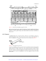
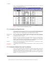
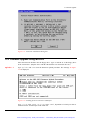
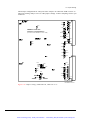
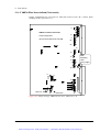
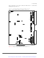
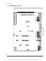
1
Artisan Technology Group is your source for quality new and certified-used/pre-owned equipment • FAST SHIPPING AND DELIVERY • TENS OF THOUSANDS OF IN-STOCK ITEMS • EQUIPMENT DEMOS • HUNDREDS OF MANUFACTURERS SUPPORTED • LEASING/MONTHLY RENTALS • ITAR CERTIFIED SECURE ASSET SOLUTIONS SERVICE CENTER REPAIRS Experienced engineers and technicians on staff at our full-service, in-house repair center WE BUY USED EQUIPMENT Sell your excess, underutilized, and idle used equipment We also offer credit for buy-backs and trade-ins www.artisantg.com/WeBuyEquipment InstraView REMOTE INSPECTION LOOKING FOR MORE INFORMATION? Visit us on the web at www.artisantg.com for more information on price quotations, drivers, technical specifications, manuals, and documentation SM Remotely inspect equipment before purchasing with our interactive website at www.instraview.com Contact us: (888) 88-SOURCE | [email protected] | www.artisantg.com User's Manual VBT-325 - VME Bus Analyzer Including XMEM325-PB Version 2.0 Valid for Firmware Version 5.5x / BusView 2.5x VBT-325B VMEbus Analyzer VBT-325C VMEbus & VSB/SCSI/P2 Analyzer XMEM325-PB Extended Trace memory for the VBT-325 Copyright VMETRO 1997. No part of this document may be furnished or disclosed to any third party, and it may not be copied or reproduced in any form, electronic, mechanical, or otherwise, without written permission from VMETRO Inc. (Houston, TX, USA) or VMETRO asa (Oslo, Norway). The Bus Analyzer Specialist Artisan Technology Group - Quality Instrumentation ... Guaranteed | (888) 88-SOURCE | www.artisantg.com Warranty VMETRO products are warranted against defective materials and workmanship within the warranty period of 1 (one) year from date of invoice. Within the warranty period, VMETRO will, free of charge, repair or replace any defective unit covered by this warranty, shipping prepaid. A Return Authorization Code should be obtained from VMETRO prior to return of any defective product. With any returned product, a written description of the nature of malfunction should be enclosed. The product must be shipped in its original shipping container, or similar packaging, with sufficient mechanical and electrostatic protection, in order to maintain warranty. This warranty assumes normal use. Products subjected to unreasonably rough handling, negligence, abnormal voltages, abrasion, unauthorized parts replacement and repairs, or theft are not covered by this warranty and will be repaired for time and material charges in effect at the time of repair. VMETRO’s warranty is limited to the repair or replacement policy described above and neither VMETRO nor its agent shall be responsible for consequential or special damages related to the use of their products. VMETRO, Inc. USA: 1880 Dairy Ashford, #535 HOUSTON, TX 77077, USA Tel: (281) 584-0728 Fax: (281) 584-9034 VMETRO asa Europe, Asia: Brynsveien 5 0667 OSLO, Norway Tel: +47 22 10 60 90 Fax: +47 22 10 62 02 ii User's Manual VBT-325 Artisan Technology Group - Quality Instrumentation ... Guaranteed | (888) 88-SOURCE | www.artisantg.com VMETRO Preface This Manual This manual covers the VBT-325 and the XMEM325-PB piggyback module, and corresponds to firmware versions 5.5x / BusView 2.5x. The XMEM325-PB is described separately only under the “XMEM325-PB Piggyback Module”, “Product overview” and “Installation”. All other instructions governing the operation of the piggyback module are identical to those for the VBT-325, and is found in the general text. VMETRO User's Manual VBT-325 Artisan Technology Group - Quality Instrumentation ... Guaranteed | (888) 88-SOURCE | www.artisantg.com iii The Bus Analyzer concept A Bus Analyzer is a pre-configured logic analyzer designed as a plug-in card for a specific bus, conforming to the logical, electrical and mechanical specification of the target bus. The primary use of a Bus Analyzer is to monitor the activity on a back plane bus and provide a trace of bus cycles between modules on the bus, presenting this as alphanumeric trace lists or as waveforms on a standard ASCII terminal. This is done without the need for connecting and configuring large numbers of probes to the back plane, a time-consuming and error-prone process necessary with general-purpose logic analyzers. Statistics analysis in bus systems is also an important application for bus analyzers. A basic idea behind bus analyzers is that the analyzer is "hard-wired" to capture the protocol of the target bus, thereby reducing the need for the user to understand all the details of the bus protocol in order to perform meaningful analysis of activity in the target system. This offers the user maximum productivity and convenience during development, debugging, testing and verification of bus based computer systems. VMETRO is a company totally committed to building the finest Bus Analyzers, and is recognized in development labs around the world as providing superior tools for developers and manufacturers of bus based computer equipment. With the VBT-325, VMETRO offers the fourth generation, state-of-the art product based on 10 years of experience in building bus analyzers. The Bus Analyzer Specialist iv User's Manual VBT-325 Artisan Technology Group - Quality Instrumentation ... Guaranteed | (888) 88-SOURCE | www.artisantg.com VMETRO CONTENTS CONTENTS 1. GETTING STARTED ......................................................................................... 1 1.1 Getting Started with BusView.........................................................................................................1 1.2 Getting Started Using a Terminal User Interface ........................................................................3 2. INSTALLATION ................................................................................................. 7 2.1 Static Electricity - Precautions........................................................................................................7 2.2 Preparations ......................................................................................................................................7 2.2.1 Inspection ................................................................................................................................7 2.2.2 Jumper Settings .......................................................................................................................8 2.2.3 P2 rows A and C......................................................................................................................8 2.2.4 TTL/CMOS Input only (0-5V) ................................................................................................8 2.3 Slot Selection .....................................................................................................................................9 2.3.1 VMEbus...................................................................................................................................9 2.3.2 VSB .........................................................................................................................................9 2.3.3 Daisy-Chains ...........................................................................................................................9 2.3.4 Slot 1........................................................................................................................................9 2.3.5 User-defined P2.......................................................................................................................9 2.4 Power Consumption .......................................................................................................................10 2.4.1 Air Cooling............................................................................................................................10 2.4.2 5V Readout............................................................................................................................11 2.4.3 +/-12V Supplies.....................................................................................................................11 2.4.4 FLASH 12V Jumper..............................................................................................................11 2.4.5 External Power ......................................................................................................................11 2.5 BusView for Windows - Graphical User Interface.....................................................................13 2.5.1 System Requirements ............................................................................................................13 2.5.2 Installing BusView on the PC ...............................................................................................13 2.5.3 Connecting the VBT-325 to the PC ......................................................................................13 2.5.4 Troubleshooting: Connection Problems ................................................................................14 2.6 Terminal User Interface ................................................................................................................15 2.6.1 Establish a Connection ..........................................................................................................15 2.6.2 Start-up Menu........................................................................................................................16 2.7 RS-232 Communication .................................................................................................................17 2.7.1 Terminal cable .......................................................................................................................18 VMETRO User's Manual VBT-325 Artisan Technology Group - Quality Instrumentation ... Guaranteed | (888) 88-SOURCE | www.artisantg.com v CONTENTS 2.7.2 PC Cable ............................................................................................................................... 19 2.7.3 Transparent mode.................................................................................................................. 19 2.8 Accessories ...................................................................................................................................... 20 3. FUNCTIONAL DESCRIPTION.......................................................................21 3.1 Product Overview .......................................................................................................................... 21 3.1.1 Model B and C ...................................................................................................................... 21 3.1.2 Specification Highlights........................................................................................................ 23 3.1.3 Piggyback modules ............................................................................................................... 23 3.1.4 Piggyback Carrier (VPC-MkII)............................................................................................. 24 3.2 Sampling Modes ............................................................................................................................. 25 3.2.1 STATE (Synchronous) Sampling ......................................................................................... 25 3.2.2 TIMING (Asynchronous) Sampling ..................................................................................... 26 3.3 Main Blocks .................................................................................................................................... 26 3.3.1 Sampling stage ...................................................................................................................... 27 3.3.2 Word Recognition / Triggering stage.................................................................................... 28 3.3.3 Sample Storage stage ............................................................................................................ 29 3.3.4 Statistics Counters................................................................................................................. 30 3.4 Sampling Methods.......................................................................................................................... 30 3.4.1 VMEbus STATE Sampling .................................................................................................. 30 3.4.2 VSB STATE Sampling ......................................................................................................... 32 3.4.3 SCSI STATE Sampling ........................................................................................................ 32 3.4.4 VXI Sampling ....................................................................................................................... 33 3.4.5 User-defined P2 STATE Sampling....................................................................................... 33 3.5 External Inputs............................................................................................................................... 34 3.5.1 In3:0 in VME Part................................................................................................................. 34 3.5.2 In3:0 to P2 Part Using Cross-trigger..................................................................................... 34 3.5.3 Shared In3:0 and Time Tag Bits ........................................................................................... 34 3.5.4 Shared In1 and Temperature Probe....................................................................................... 34 4. XMEM325-PB.....................................................................................................35 4.1 Product Overview .......................................................................................................................... 35 4.1.1 Main Blocks .......................................................................................................................... 35 4.2 Installation ...................................................................................................................................... 36 4.2.1 Mounting............................................................................................................................... 36 4.2.2 Removal ................................................................................................................................ 37 4.2.3 Power Consumption.............................................................................................................. 38 vi • Contents User's Manual VBT-325 Artisan Technology Group - Quality Instrumentation ... Guaranteed | (888) 88-SOURCE | www.artisantg.com CONTENTS 5. OPERATION...................................................................................................... 40 5.1 Window Elements and Commands...............................................................................................40 5.2 Using BusView ................................................................................................................................41 5.2.1 Mouse Control .......................................................................................................................41 5.2.2 Keyboard Control ..................................................................................................................41 5.3 User-Interface Structure ...............................................................................................................42 5.3.1 Functional Units ....................................................................................................................42 5.3.2 Window Categories ...............................................................................................................42 5.3.3 Setup Window .......................................................................................................................42 5.3.4 Trace Display Window..........................................................................................................43 5.3.5 Statistics Window..................................................................................................................44 5.4 Event Patterns.................................................................................................................................44 5.4.1 Editing Event Patterns ...........................................................................................................45 5.4.2 Address/Data Options............................................................................................................48 5.5 Single Event Mode ..........................................................................................................................50 5.6 Sequencer Mode..............................................................................................................................51 5.6.1 Tutorial ..................................................................................................................................52 5.6.2 Sequencer - a State Machine .................................................................................................57 5.6.3 Open Sequencer.....................................................................................................................58 5.6.4 Edit Sequencer.......................................................................................................................59 5.6.5 Sequencer Reference .............................................................................................................61 5.6.6 Sequencer Programming Examples.......................................................................................68 5.7 Trace Display ..................................................................................................................................73 5.7.1 Alphanumeric Trace List .......................................................................................................73 5.7.2 Waveforms ............................................................................................................................76 5.7.3 Additional Windows..............................................................................................................79 5.7.4 Trace Dump to PC/Host ........................................................................................................79 5.8 Statistics...........................................................................................................................................80 5.8.1 Counters Operation................................................................................................................80 5.8.2 Event Counting......................................................................................................................81 5.8.3 Bus Utilization, VME............................................................................................................82 5.8.4 Bus Transfer Rate ..................................................................................................................84 5.8.5 Statistics Options ...................................................................................................................85 5.9 Cross-triggering..............................................................................................................................90 5.9.1 Cross-trigger VSB from VME...............................................................................................91 6. COMMANDS REFERENCE............................................................................ 93 VMETRO User's Manual VBT-325 Artisan Technology Group - Quality Instrumentation ... Guaranteed | (888) 88-SOURCE | www.artisantg.com vii CONTENTS 6.1 File Menu ........................................................................................................................................ 93 6.1.1 New Setup............................................................................................................................. 93 6.1.2 Open...................................................................................................................................... 93 6.1.3 Save, Save as......................................................................................................................... 93 6.1.4 Print....................................................................................................................................... 93 6.1.5 Printer Setup.......................................................................................................................... 94 6.1.6 Save Settings on Exit ............................................................................................................ 94 6.1.7 Exit........................................................................................................................................ 94 6.2 Edit Menu........................................................................................................................................ 94 6.2.1 Undo...................................................................................................................................... 94 6.2.2 Cut......................................................................................................................................... 95 6.2.3 Copy...................................................................................................................................... 95 6.2.4 Paste ...................................................................................................................................... 95 6.2.5 Clear...................................................................................................................................... 95 6.2.6 Insert ..................................................................................................................................... 95 6.2.7 Open Sequencer .................................................................................................................... 96 6.2.8 Trigger Position .................................................................................................................... 96 6.2.9 Sampling Mode ..................................................................................................................... 96 6.3 Trace Menu..................................................................................................................................... 97 6.3.1 Run <Target>........................................................................................................................ 97 6.3.2 Run Multiple ......................................................................................................................... 97 6.3.3 Halt........................................................................................................................................ 98 6.3.4 Halt All.................................................................................................................................. 98 6.3.5 Show <Target> ..................................................................................................................... 98 6.3.6 Sampling Status..................................................................................................................... 98 6.4 Statistics .......................................................................................................................................... 98 6.5 Setups Menu ................................................................................................................................... 99 6.5.1 Initialize ................................................................................................................................ 99 6.5.2 Load ...................................................................................................................................... 99 6.5.3 Store ...................................................................................................................................... 99 6.5.4 Delete .................................................................................................................................... 99 6.5.5 Make Current ...................................................................................................................... 100 6.6 Utilities Menu ............................................................................................................................... 100 6.6.1 Communication................................................................................................................... 100 6.6.2 Update Tracer Firmware ..................................................................................................... 100 6.6.3 Clear Non-Volatile Memory ............................................................................................... 100 6.6.4 Transparent Mode ............................................................................................................... 101 viii • Contents User's Manual VBT-325 Artisan Technology Group - Quality Instrumentation ... Guaranteed | (888) 88-SOURCE | www.artisantg.com CONTENTS 6.6.5 Target Reconfigure..............................................................................................................101 6.6.6 Trigger Output Options .......................................................................................................101 6.6.7 LED Display........................................................................................................................102 6.6.8 Simulated Hardware ............................................................................................................102 6.6.9 User Interface Options.........................................................................................................102 6.6.10 Selftest ...............................................................................................................................103 6.6.11 Reset Analyzer...................................................................................................................103 6.6.12 Specials..............................................................................................................................103 6.7 Window Menu...............................................................................................................................104 6.7.1 Cascade................................................................................................................................104 6.7.2 Tile Horizontally..................................................................................................................104 6.7.3 Tile Vertically......................................................................................................................104 6.7.4 Arrange Icons ......................................................................................................................104 6.7.5 Alphanumeric List ...............................................................................................................104 6.7.6 Waveform ............................................................................................................................104 6.7.7 Select Window.....................................................................................................................105 6.8 Help Menu .....................................................................................................................................105 6.8.1 Index ....................................................................................................................................105 6.8.2 Topic Search........................................................................................................................105 6.8.3 Using Help...........................................................................................................................105 6.9 Trace Display ................................................................................................................................105 6.9.1 Search menu ........................................................................................................................106 6.9.2 Jump Menu ..........................................................................................................................107 6.9.3 Count ...................................................................................................................................108 6.9.4 Format Menu .......................................................................................................................109 6.9.5 Marker Menu .......................................................................................................................110 6.10 Statistics.......................................................................................................................................111 6.10.1 Session Menu ....................................................................................................................111 6.10.2 Function Menu...................................................................................................................111 6.10.3 Options ..............................................................................................................................112 7. SIGNAL REFERENCE................................................................................... 115 7.1 VMEbus Signal Fields..................................................................................................................115 7.1.1 Default Signal Fields in STATE Mode ...............................................................................115 7.1.2 Cross-trigger Signals ...........................................................................................................118 7.1.3 Default Signal Fields in Timing Mode ................................................................................118 7.1.4 Signal Fields not Included by Default .................................................................................119 VMETRO User's Manual VBT-325 Artisan Technology Group - Quality Instrumentation ... Guaranteed | (888) 88-SOURCE | www.artisantg.com ix CONTENTS 7.2 VSB Signal Fields ......................................................................................................................... 120 7.2.1 VSB, Default Signal Fields in STATE Mode ..................................................................... 120 7.2.2 VSB, Default Signal Fields in TIMING Mode ................................................................... 122 7.2.3 VSB, Signal Fields not Included by Default ....................................................................... 123 7.3 SCSI Signal Fields ........................................................................................................................ 123 7.3.1 SCSI, Default Signal Fields in STATE Mode .................................................................... 123 7.3.2 SCSI, Default Signal Fields in TIMING Mode................................................................... 124 7.3.3 SCSI, Signal Fields not Included by Default ...................................................................... 124 7.4 VXI Signal Groups....................................................................................................................... 124 7.4.1 VXI, Default Signal Fields in STATE and TIMING Modes .............................................. 125 8. PINOUT P1/P2..................................................................................................127 8.1 VME & VSB Connection on P1 & P2 ........................................................................................ 127 8.2 SCSI Connection on P2 ............................................................................................................... 127 8.2.1 VBT-325 SCSI P2 adapter.................................................................................................. 129 8.3 Customized Isolation of P2a/c .................................................................................................... 130 9. TERMINAL USER INTERFACE ..................................................................133 9.1 Using a Terminal Instead of BusView ....................................................................................... 133 9.1.1 Keyboard Control................................................................................................................ 133 9.1.2 Screen Categories................................................................................................................ 133 9.1.3 Setup Screen........................................................................................................................ 134 9.1.4 Trace Display Screen .......................................................................................................... 142 9.2 VMETRO VT100 Terminal Emulator ...................................................................................... 144 9.2.1 Starting the VT100.............................................................................................................. 146 9.2.2 VT100 Environment Variable............................................................................................. 146 9.2.3 Terminal Types to Use on the Tracer.................................................................................. 146 9.2.4 Built-in Script Language ..................................................................................................... 147 9.3 P2ac User defined tracer, Terminal only .................................................................................. 150 9.3.1 Slot Selection ...................................................................................................................... 150 9.3.2 Jumper Settings ................................................................................................................... 151 9.3.3 Sampling Clock Select ........................................................................................................ 151 9.3.4 P2 Cross Trigger Jumper .................................................................................................... 151 9.3.5 Commands Reference ......................................................................................................... 152 9.3.6 Using time tags.................................................................................................................... 156 9.3.7 Dump/Load Setup to/from PC/Host.................................................................................... 157 x • Contents User's Manual VBT-325 Artisan Technology Group - Quality Instrumentation ... Guaranteed | (888) 88-SOURCE | www.artisantg.com CONTENTS 10. SIMULATOR FOR PC ................................................................................. 159 10.1 Installation...................................................................................................................................159 10.2 Simulate Bus Activity.................................................................................................................159 10.3 Trace Files ...................................................................................................................................159 11. TRACE FILE FORMAT............................................................................... 161 11.1 Trace File Format.......................................................................................................................161 11.2 Trace Data Line format, VBT-325 ...........................................................................................164 11.3 Details of the Time Tag Variables ............................................................................................164 11.4 Converting the Time Tag to a Time Value ..............................................................................165 11.5 Details of Internally Generated Bits.........................................................................................166 11.6 Details of the Am, Irq, Str, Bg, St2 and St3 bytes...................................................................166 11.7 Differences for the XMEM325-PB VME.................................................................................167 11.8 Trace Data Line Format, VSB targets .....................................................................................167 11.8.1 Details of St4 and St5 bytes...............................................................................................168 11.9 Trace Data Line format, SCSI targets .....................................................................................168 11.10 BusView Trace File Format ....................................................................................................169 12. FIRMWARE UPGRADE.............................................................................. 174 12.1 Firmware Upgrade Preparations .............................................................................................174 12.1.1 Diskette for PCs.................................................................................................................174 12.1.2 Boot PROM.......................................................................................................................174 12.1.3 RS232 Connection.............................................................................................................174 12.1.4 Power on the FLASH EPROMs ........................................................................................174 12.2 Firmware Upgrade Using BusView..........................................................................................174 12.3 Firmware Upgrade Using MS-DOS .........................................................................................175 12.4 Troubleshooting - Firmware Upgrade .....................................................................................177 12.4.1 If Upload Stops..................................................................................................................177 12.4.2 Communication Errors ......................................................................................................178 12.4.3 Flash Memory Errors.........................................................................................................178 12.4.4 Tuning Parameters Lost.....................................................................................................178 13. JUMPER SETTINGS .................................................................................... 182 13.1 Jumper Settings ..........................................................................................................................182 13.1.1 VBT-325............................................................................................................................182 13.1.2 VME & VSB (Twin mode) ...............................................................................................183 13.1.3 VME & SCSI (Twin mode)...............................................................................................186 VMETRO User's Manual VBT-325 Artisan Technology Group - Quality Instrumentation ... Guaranteed | (888) 88-SOURCE | www.artisantg.com xi CONTENTS 13.1.4 VME & VXI (Twin mode)................................................................................................ 188 13.1.5 VME & P2ac User-defined (Twin mode) ......................................................................... 190 13.1.6 XMEM325-VME, VSB & VXI........................................................................................ 192 13.1.7 XMEM325-VME & SCSI ................................................................................................ 193 13.1.8 XMEM325-VME & P2ac User-defined ........................................................................... 194 14. APPENDIX A..................................................................................................195 14.1 List of Figures............................................................................................................................. 195 14.2 List if Tables ............................................................................................................................... 198 15. INDEX..............................................................................................................201 xii • Contents User's Manual VBT-325 Artisan Technology Group - Quality Instrumentation ... Guaranteed | (888) 88-SOURCE | www.artisantg.com 1 Getting Started 1. GETTING STARTED 1.1 Getting Started with BusView This is a short introduction to the VME Bus Analyzer VBT-325, including references to sections throughout the manual. The VBT-325 has a lot of powerful features (see Section 3.1.2), but the essence is that the user defines a signal pattern (in the Event Patterns window), the tracer recognizes the pattern when it occurs on the PCI bus (triggering), and then fills a trace buffer with samples of the PCI bus signals in an interval around the trigger sample. The following steps have to be carried out before BusView is ready to run: • Install the tracer according to Section 2.2. • Install BusView according to the description in Section 2.5.2. • Set the communication parameters, and connect the tracer as described in Section 2.5.3. If everything is installed correctly, BusView should now display the setup window shown in Figure 1.1. The Setup window is divided in two, the Event Patterns window, and the Sequencer window. For further information about the Setup Window, read Section 5.3.3. Sampling The VBT-325 has two sampling modes, STATE (default) and TIMING mode. Section 3.2 includes a detailed description of the sampling modes. Trace/Run Select Trace/Run from the menu bar, (or press the “lightning” button at the tool bar), to get a snap shot of the current bus activity. The Trace window is displayed, see Figure 1.2. The contents of the Trace window depends on the current bus traffic. Ctrl-Tab Switch back to the Setup window by pressing the Ctrl-key together with the Tab-key, or by using the mouse. Operating BusView is described in Section 5.2. TIMING mode Change sampling mode to TIMING mode by selecting Edit/Sampling mode/50MHz Timing from the menu bar. Notice that the first line in the Sequencer window now displays “Sampling in TIMIMG mode”. VMETRO User's Manual VBT-325 Artisan Technology Group - Quality Instrumentation ... Guaranteed | (888) 88-SOURCE | www.artisantg.com 1 1 Getting Started Event Patterns window Sequencer window Figure 1.1 The Setup window Figure 1.2 The Trace Display window Trace/Run 2 Select Trace/Run once more, and after a few moments the waveform version of the Trace window appears. The waveform window is shown in Figure 1.3. To avoid sampling while the VME bus is idle, it is necessary to set up a trigger condition. Click on AS* in the Event Patterns window on the VME0 line and type a 0. User's Manual VBT-325 Artisan Technology Group - Quality Instrumentation ... Guaranteed | (888) 88-SOURCE | www.artisantg.com VMETRO 1 Getting Started Figure 1.3 The waveform window 1.2 Getting Started Using a Terminal User Interface The following steps have to be carried out before the terminal is ready to run: • Install the tracer according to Section 2.2. • Follow the instructions in Section 2.6.1 for establishing a connection between the terminal and the tracer. If everything proceeded correctly the terminal should now display the setup screen shown in Figure 1.4. The Setup screen is divided in two, the Event Patterns window, and the Sequencer window. For further information about the Setup screen, read Section 5.3.3 and Section 9.1.3. Sampling The VBT-325 has two main sampling modes, TIMING and STATE (default) mode. Section 3.2 includes a detailed description of the sampling modes. Trace/Run Type <T> and <R> to execute the command Trace/Run. The Trace window displays a snap shot of the current bus activity, see Figure 1.5. The contents of the Trace window depends on the current bus traffic. Quit Type <Q> to quit the Trace Display screen and return to the Setup screen. TIMING mode Change sampling mode to TIMING mode by selecting Edit/Sampling Mode/50MHz Timing from the menu bar. Notice that the first line in the Sequencer window now displays “Sampling in TIMING mode”. VMETRO User's Manual VBT-325 Artisan Technology Group - Quality Instrumentation ... Guaranteed | (888) 88-SOURCE | www.artisantg.com 3 1 Getting Started Figure 1.4 The Setup screen, terminal view Trace/Run Type <T> and <R> to execute the command Trace/Run once more. After a few moments the waveform version of the Trace window appears. The waveform window is shown in Figure 1.6. To avoid sampling while the VME bus is idle, it is necessary to set up a trigger condition. Type <i> and <e> to enable editing in the Event Patterns window. With the cursor keys, select the AS* field in the VME0 line, and type a 0. Figure 1.5 The Trace Display screen, terminal view 4 User's Manual VBT-325 Artisan Technology Group - Quality Instrumentation ... Guaranteed | (888) 88-SOURCE | www.artisantg.com VMETRO 1 Getting Started Figure 1.6 The Waveform window, terminal view VMETRO User's Manual VBT-325 Artisan Technology Group - Quality Instrumentation ... Guaranteed | (888) 88-SOURCE | www.artisantg.com 5 1 Getting Started 6 User's Manual VBT-325 Artisan Technology Group - Quality Instrumentation ... Guaranteed | (888) 88-SOURCE | www.artisantg.com VMETRO 2 Installation 2. INSTALLATION 2.1 Static Electricity - Precautions Before unpacking the VBT-325 from its shipping container, make sure that it takes place in an environment with controlled static electricity. The following recommendations should be followed: • Make sure your body is discharged to the static voltage level on the floor, table and system chassis by wearing the enclosed conductive wrist-strap, or similar. • If a conductive wrist-strap is not available, touch the surface where the board is to be put (like table, chassis etc.) before unpacking the board. • Leave the board only on surfaces with controlled static characteristics, i.e. specially designed anti-static table covers. • If handing the board over to another person, touch this persons hand, wrist etc. to discharge any static potential. 2.2 Preparations 2.2.1 Inspection Make sure that the VBT-325 you have received is according to your purchase order with respect to model. The VBT-325 model B and model C can be distinguished by looking at the label on the big MACH PLD device on the board. You will find either the text VBT325B or VBT-325C on this label. With the VBT-325 you should find the following accessories: • A small plastic bag with spare jumpers (for reconfiguration of the board). • A small plastic bag containing an anti-ESD wrist wrap. • One BNC-to-MiniCoax cable 3ft/1m (for Ext. Input/Trigger Output). • Diskette with the Simulator (Chapter 10) and the VT100 Terminal Emulator (Section 9.2). • PC cable (part number 401-PC-232) if BusView is purchased. Note! VMETRO You should also inspect the board to verify that no mechanical damage appears to have occurred. Please report any discrepancies or damage to your distributor or to VMETRO immediately. User's Manual VBT-325 Artisan Technology Group - Quality Instrumentation ... Guaranteed | (888) 88-SOURCE | www.artisantg.com 7 2 Installation 2.2.2 Jumper Settings Model Target Bus Mode (Wide/Twin) VBT-325B VBT-325C VBT-325C VBT-325C VBT-325C VME VME & VSB VME & SCSI VME & P2 Futurebus+ Twin Twin Twin Wide Factory setting x (only option) x (only option) Table 2.1 Jumper settings There are a number of jumpers on the VBT-325 board that define target bus, operating mode (Wide/Twin) and RS232 handshake bypass. VBT-325C The factory setting for the VBT-325C is twin mode, VMEbus & VSB (except VSB BGIN/OUT* daisy-chain bypass, see Section 13.1.2). VBT-325B For the VBT-325B, the only possible configuration is VMEbus, so there is never a need to reconfigure jumpers on this model, unless the board is upgraded to a model C or the RS232 handshake bypass between terminal/host is used. Chapter 13 has the correct jumper setting for the other possibilities listed in Table 2.1. 2.2.3 P2 rows A and C No pins on the P2 rows A and C are driven, connected, or grounded in the factory jumper setting. However, this may change after configuring the board for VSB and SCSI. The jumper J64, for VSB BGIN/OUT*, (see Section 13.1.2) will connect P2a31-c32 when installed, and may cause problems in systems using other P2 configurations. Similarly, grounding of the SCSI bus takes place with four jumpers in field J51 (see Section 13.1.3), and these must not be in place when used with other P2 busses. 2.2.4 TTL/CMOS Input only (0-5V) Warning! The input channels on the VBT-325 are designed for TTL/CMOS voltage levels only (0.05.0V), and damage may occur if other voltages are applied. Max 5.25V Absolute maximum tolerated input voltage is 5.25V. If the P2 bus contains signals with voltage levels other than TTL/CMOS, (for example ECL, analogue or special power supply voltages as found in VXI systems), these must be isolated from the VBT-325. (For this purpose, VMETRO offers a special adapter, the VXE-35C, which extends the VBT-325C to fit in C-size VXI systems and isolates the non-TTL signals from the back plane. Refer to a separate data sheet for detailed information.) 2.2.4.1 Isolation of P2 rows A and C Isolation of the P2 pins with illegal voltage levels can be done in one of the following ways: • Place the VBT-325 in a slot without the illegal voltages on the P2 connector. • Place the VBT-325 on an extender board which isolates the signals with illegal voltage. (For VXI, use VMETRO's VXE-35C), see Section 2.2.4. 8 User's Manual VBT-325 Artisan Technology Group - Quality Instrumentation ... Guaranteed | (888) 88-SOURCE | www.artisantg.com VMETRO 2 Installation • Customize your VBT-325 by cutting the copper tracks that are specially laid out for all P2 signals for this purpose. These can be found as a row of 32 pairs of solder pads connected with a thin copper track on each side of the board just next to the P2 connector. The pads on the bottom side are signals from P2 row C, and the pads on the top side row A. If a connection needs to be re-established, a short piece of unisolated wire (AWG30 or similar) can be soldered between the two pads in a pair. See Section 8.3 2.3 Slot Selection 2.3.1 VMEbus The VBT-325 can be installed in any slot in a VME back plane. However, it is recommended that the VBT-325 is located as far to the left (closest to slot #1) as possible. This ensures that the Bus Grants (BG3-0IN/OUT*) and IACKIN/ OUT* daisychains pass the VBT-325, and these signals are captured by the analyzer. The bus grants are of special interest since the VBT-325 contains special circuitry to sample these signals even in synchronous (STATE) sampling mode (see Section 3.2). 2.3.2 VSB Similarly, for analysis of VSB back planes it is recommended to place the VBT-325C as far to the left as possible on the VSB back plane to ensure that the VSB Bus Grant (BGIN/OUT*) daisy-chain pass the VBT-325C. This is relevant if asynchronous sampling (TIMING mode) is used to see the bus arbitration process (serial arbitration). 2.3.3 Daisy-Chains The VBT-325 will bypass the VMEbus daisy-chains BG(3-0)IN/OUT* and IACKIN/OUT* directly. The VSB BGIN/OUT* daisy-chain is not installed in the factory setting. The user may want to install this before using the board in a VSB system, see Section 13.1.2. 2.3.4 Slot 1 When the VDRIVE-PB piggyback module is installed, the VBT-325 may be placed in slot #1 if the VDRIVE-PB is configured as System Controller. Refer to the VDRIVE-PB User's Manual. Note! Bus grants received by any Bus Master located to the left of the VBT-325 (lower slot number) will not be visible to the analyzer, due the nature of VME/VSB daisy-chaining. Similarly, IACKIN/OUT* received by any Interrupter located to the left of the VBT325 (lower slot number) will not be visible to the analyzer. 2.3.5 User-defined P2 In order to perform bus analysis of a user-defined P2 bus, one must make sure that the slot where the VBT-325C is inserted has access to the user-defined bus on the A- and C- rows of the P2 connector. In many cases, the P2 bus is taken directly with a flat cable from the P2 connector on a VME board to an I/O device, without any form of bussing of the P2 bus VMETRO User's Manual VBT-325 Artisan Technology Group - Quality Instrumentation ... Guaranteed | (888) 88-SOURCE | www.artisantg.com 9 2 Installation along the back plane. In such cases, the user should insert the VBT-325C in a neighbor slot to the board that has the P2 bus, and provide an "L-shaped" extension of the flat cable to the slot of the VBT-325C (see Figure 2.1). VME/P2 backplane VBT-325C Analyzer Extended flatcable for analysis by VBT-325C VME board with P2 I/O bus <Top view> Flatcable on P2 a/c connector To I/O device Figure 2.1 Sampling of User-defined P2 bus Note! User-defined P2 is not supported under BusView. 2.4 Power Consumption The VBT-325 is normally powered directly from the +5V and +/- 12V rails in the VME back plane, and it is important to make sure that the power supply in the card crate has sufficient capacity to supply the VBT-325. Current consumption is depending on operating mode, as given below: +5V 2.8A typical when idle. Sampling 3.7A typical @ 6MHz, VME only. 4.8A typical @ 50MHz, VME only. 5.4A typical @ 50MHz, VME and P2. +/-12V 10mA typical. (+12V/120mA max. when programming FLASH EPROM only.) VPC-MkII Warning! The VPC-MkII consumes about 1.1A @ 5.0V. The consumption at 12V is as for the VBT325. Make sure that the board is always powered both from the P1 and P2 connectors. 2.4.1 Air Cooling Forced air cooling is necessary to keep the operating temperature of the VBT-325 board at reasonable levels. The power consumption varies depending on the state the board is in, from app. 14W when idle, to almost the double when sampling all channels at maximum speed. 10 User's Manual VBT-325 Artisan Technology Group - Quality Instrumentation ... Guaranteed | (888) 88-SOURCE | www.artisantg.com VMETRO 2 Installation 2.4.2 5V Readout The front panel LED display will show the actual 5V voltage supplied to the VBT-325 when user interface is started. A reading of at least 4.95V is recommended when the board is idle. This normally gives sufficient margin for the increase in power consumption when the analyzer is running. Be aware that if the VBT-325 is placed on an extender board, there may be excessive voltage drop which may need to be compensated by increasing the system voltage slightly. 2.4.3 +/-12V Supplies The VBT-325 board uses +/-12V for powering the voltage and temperature monitoring circuitry, and it uses +12V for programming the onboard Flash EPROMs. The RS232 transceivers operate independently from the +/-12V supply. Warning! If the voltage on the +/- 12V pins in the back plane is higher than 12V, severe damage may occur! 2.4.4 FLASH 12V Jumper The +12V supply from the back plane is normally connected to the FLASH EPROM devices via jumper J67. This jumper is, by default, installed as shown in the illustration in Figure 2.2. The +12V supply is disconnected from the FLASH EPROM by moving jumper J67 to the opposite position. Move jumper J67 to the upper position if the stability of the +12V supply is in doubt. Moving J67 will not prevent damage to the voltage/temperature monitoring circuitry and de-coupling capacitors if the voltage exceeds +15V. Figure 2.2 FLASH EPROM 12V jumper 2.4.5 External Power By repositioning two power jumpers the VBT-325 can also be powered from an external +5V power source through a front panel inlet.1 This is useful if there is insufficient 1 Connector type: Molex, Part #5557-02R with 5556-TL terminals. VMETRO can supply cable with connector, VMETRO part # 401-325EPC. VMETRO User's Manual VBT-325 Artisan Technology Group - Quality Instrumentation ... Guaranteed | (888) 88-SOURCE | www.artisantg.com 11 2 Installation capacity in the power supply in the card crate to supply the additional current required by the VBT-325. External power supply also allows tracing the activity in a VME system during power up sequences. When powered from an external 5V supply, the +/-12V is still supplied from the back plane. However, this is only used for powering the voltage and temperature readout circuitry, and for programming of FLASH EPROM during firmware upgrades. Thus, it is fully possible to operate the board only from an external 5V supply, keeping in mind that the functions mentioned above will not be operational. There are two "heavy-duty" jumpers (blue, with handle) that connects 5V power to the board from the VME back plane or from the external power source through the front panel inlet, see Figure 2.3. The factory setting of these jumpers are in the Z1 and Z2 positions between the P1 and P2 connectors, supplying 5V from the VME back plane. To allow for external power supply, move both jumpers to the Z3 and Z4 positions on each side of the power inlet connector. Warning! Both jumpers have to be moved! Moving only one jumper will connect the external power supply’s +5V to the system’s +5V, causing excessive ground currents and other undesired effects. Trigger output P1 Ext.inputs (0-3) Alphanumeric Display Z2 Z1 & Z2: Power Jumper positions for VME power Reset switch Z1 Terminal port (RS232) 1234 N1, N2: RS-232 handshake jumpers. (Terminal-Host handshake bypass) Host/Printer port (RS232) Ext. Power Adapter connector (used with FBA-625 Futurebus+ adapter) P2 Z3 Z4 Z3 & Z4: Power Jumper positions for EXT power Figure 2.3 Powering the VBT-325 from an external power source 12 User's Manual VBT-325 Artisan Technology Group - Quality Instrumentation ... Guaranteed | (888) 88-SOURCE | www.artisantg.com VMETRO 2 Installation 2.5 BusView for Windows - Graphical User Interface BusView is a graphical user interface for the VBT-325. It offers a user-friendly mouse operation of the analyzer system, higher resolution graphics than can be achieved with a normal terminal, a multi-window operating environment, and the capability to store trace data and setups on disk. This chapter describes the procedures required to install BusView on a PC and to setup the VBT-325 for operation under BusView. 2.5.1 System Requirements The PC system where BusView is to be installed, must meet the following requirements. • Have Windows 3.1x, Windows 95, or Windows NT (3.5x or 4.0) installed and running. BusView also supports OS2/Warp 3.0 and higher. • Pentium PC. • Have at least 8 Mbytes RAM. • Have at least 16 Mbytes of free disk space. • Have at least one free serial port for connection to the VBT-325 (BusView can run in off-line mode even when no serial port is available). 2.5.2 Installing BusView on the PC To install BusView on a PC, perform the following steps: • Start Windows (if not already running). The BusView installation program runs under Windows. • Insert the CD-ROM into the CD-ROM drive. • Select the CD-ROM drive in the File Manager/Explorer. • Run the installation program by double-clicking on the file SETUP.EXE. • Follow the instructions in the installation program. When the installation has finished, a new Windows program group with the name BusView will be displayed. 2.5.3 Connecting the VBT-325 to the PC Communication Parameters Before communication can be established between the PC and the analyzer, the communication parameters for the PC Serial Port must be set to the correct values. In BusView, select the command Utilities/Communication /Port Settings. To change any of the displayed options click on the field to change and hold until the menu appears. In the dialog box in Figure 2.4, select the COM Port to which the analyzer is connected, and press the OK button. The settings in Windows control panel have no effect in BusView for Windows. Serial Cable Connect a serial cable between the VBT-325 and a free COM port on the PC. The cable is discussed in Section 2.7. VMETRO User's Manual VBT-325 Artisan Technology Group - Quality Instrumentation ... Guaranteed | (888) 88-SOURCE | www.artisantg.com 13 2 Installation Figure 2.4 The BusView Communication Parameters Connect To connect to the VBT-325, choose Utilities/Communication/ Connect. If the connection completed successfully, the Setup window of the analyzer will be displayed, and the unit is ready for use. For operation of the VBT-325, see Chapter 5. 2.5.4 Troubleshooting: Connection Problems There may be several reasons why a connection attempt fails, but cabling and communication settings are the most obvious. The error message in Figure 2.5 indicates a connection failure. Figure 2.5 Warning message indicating that BusView was not able to connect to the VBT-325 14 User's Manual VBT-325 Artisan Technology Group - Quality Instrumentation ... Guaranteed | (888) 88-SOURCE | www.artisantg.com VMETRO 2 Installation 2.5.4.1 Troubleshooting Checklist • Check that the LED display on the analyzer is lit. If it is not, the analyzer is not booting due to a hardware malfunction or insufficient power. • Verify that the cable used is correct. • Check the communication parameters. If the firmware is version is older than 5.30 the only possible baud rates are Auto and 9600. • Try a different COM port. • Try slowing down the “baud rate while running” • Use a multi meter and check the cable again. • Try connecting in Terminal View to verify COM port and cable. • Try connecting with a different PC. 2.6 Terminal User Interface The VBT-325 is delivered standard with a user interface for operation from a terminal (VT100 or similar), or from a terminal emulator running on a PC or UNIX workstation. For this purpose, VMETRO supplies a VT100 emulator free of charge, included on the BusView CD or the simulator diskette. See Section 9.2. 2.6.1 Establish a Connection In order to operate the VBT-325 from a terminal, do the following: • Connect a terminal (or PC / Workstation running a terminal emulator) to the serial port as described in Section 2.7. • Set the serial port of the terminal to 38K4 baud (or lower), 8 bits, 1 stop bit, no parity. • Apply power to the system. The VBT-325 can run with baud rates from 300 to 115k2 baud. By default, it is in the “auto baud rate mode”, waiting for CR (i.e.↵) to be typed to determine the actual baud rate. Any baud rate between 38k4 and 4200 baud will be detected. The baud rate can also be manually changed by the command Utilities/Serial ports. This command can also be used to change the default 8-bits, one stop-bit, no parity communication mode. Type ↵ once until text is written on the terminal screen. This text is called the start-up menu. Wait approximately 1 second between each CR due to the synchronization process. No response? 2 If the start-up menu does not appear on the screen, check that the cables are connected correctly, that the terminal / PC / WS is set to 8 bits per character, 1 stop bit and no parity, and that the baud rate is between 38k4 and 4200 baud. Flip the reset switch and try again. RTS/CTS handshake should be used when using speeds above 19K2. This feature is not implemented in the preliminary firmware. Using speeds above 19K2 is thus not recommended. VMETRO User's Manual VBT-325 Artisan Technology Group - Quality Instrumentation ... Guaranteed | (888) 88-SOURCE | www.artisantg.com 15 2 Installation Note! If the cable used has pins 7 and 8 connected, this might in some cases cause problems. The analyzer has a second RS232 port located on these pins. If the Terminal is powered up first and then the analyzer, there can in some cases appear random switching on these lines as the analyzer powers up. Some terminals interpret this as hardware handshaking and locks up. To avoid this problem use the cables specified in this manual in Section 2.7. 2.6.2 Start-up Menu After power-on, the start-up menu is written to the terminal as shown in Figure 2.6. The menu identifies product model, firmware version, baud rate, the terminal type (default or previously selected type), and the type of installed piggyback module, if any. The start-up menu contains two menu options described below. Both are activated with a single key as indicated. If no changes are required, type CR to enter the setup screen of the analyzer. Figure 2.6 The start-up menu 2.6.2.1 Select New Terminal Type The user-interface of the VBT-325 is fully screen-oriented, taking advantage of the graphical properties of VT100 compatible, and similar, terminals. This requires that the user specify which terminal or terminal emulator is being used. By typing a T, a list of the supported terminal types is given, as shown in Figure 2.7. The selected terminal type is stored in non-volatile memory, and unless this is cleared, it is not necessary to select the terminal type every time the board is powered up. Terminal type Select the preferred terminal type by typing the correct number. Use option 1 when using a VT100 emulating terminal or a terminal emulation program other than the VT100.EXE from VMETRO. This option is the default. Figure 2.7 Terminal selections 16 User's Manual VBT-325 Artisan Technology Group - Quality Instrumentation ... Guaranteed | (888) 88-SOURCE | www.artisantg.com VMETRO 2 Installation Use option 2 or 3 depending on monitor type. This requires the VT100 emulator program VT100.EXE. Option 3 will give a blue display with white text. Option 4 will give a 50 lines display with the VMETRO VT100 Terminal Emulator program, see Section 9.2 for more details on VT100.EXE. CR: Continue As soon as a number has been typed the system will return to the startup screen as in Figure 2.6. Type CR to continue. 2.6.2.2 Clear Non-Volatile Memory Type C to clear all contents of the Non-volatile RAM memory on the board. This command will cause all user setups to be lost and all settings will be reset to defaults. Use this command if a fatal software crash has occurred, e.g. if the operation of the user-interface does not behave correctly etc. Jumper J8 In case of a total hang-up of the analyzer software, the non-volatile memory may need to be cleared by removing jumper J68. Do as follows: Shut down the system and turn off the power. Locate the backup-battery jumper, J68, as shown in Figure 13.1. Move the jumper from the original left position, to the other right position, and let it remain there for a few seconds. Then, move the jumper back. When the power is re-applied, the tracer firmware should start as normal, and it will display the message "Non volatile memory lost" on the status line. Battery jumper LED Battery (blue) Figure 2.8 Back-up battery jumper 2.7 RS-232 Communication There are two serial ports on the VBT-325. One is used for connection to a terminal, PC or workstation, and the other is used for connection to a host (like a CPU board in the VME system where the VBT-325 is installed) or a printer for dumping screen images or trace data. VMETRO User's Manual VBT-325 Artisan Technology Group - Quality Instrumentation ... Guaranteed | (888) 88-SOURCE | www.artisantg.com 17 2 Installation Terminal port RxD TxD Pin 2 Pin 3 Pin 4 Pin 5 Pin 6 Pin 7 Pin 8 1 2 3 4 Handshake bypass Host/printer port MAX 233A N1 N2 Pin 2 Pin 3 Pin 4 Pin 5 Pin 6 Pin 7 Pin 8 RxD TxD Figure 2.9 Serial ports on the VBT-325 The RS-232 ports are connected as shown in Figure 2.9. Normally, only the TxD, RxD and GND (pins 2, 3 and 5) need to be connected. As can be seen, the host/printer port have the transmit/receive signals swapped compared to the terminal port. 2.7.1 Terminal cable Most terminals use a 25-pin connector (DB25) for the RS232 connection, and a cable as shown in the figure below should be used. (This cable can be purchased from VMETRO, part # 401-TER-232). Figure 2.10 Terminal cable, DB9 to DB25 converter 18 User's Manual VBT-325 Artisan Technology Group - Quality Instrumentation ... Guaranteed | (888) 88-SOURCE | www.artisantg.com VMETRO 2 Installation 2.7.2 PC Cable If a PC is used as a terminal, or when upgrading firmware through the RS232 port from a PC (see Chapter 12), a cable with crossed TxD and RxD lines must be used, see Figure 2.11. Note that the signals on pin 2 and 3 are crossed. Figure 2.11 PC cable 2.7.3 Transparent mode A convenient way of using the VBT-325 is to let the analyzer be inserted between the terminal and the CPU in your VMEbus system, so that the RS232 cable normally attached to the CPU board is instead connected to the Terminal port on the VBT-325. Then, a oneto-one RS232 cable (with pins 2, 3 and 5 connected) can be connected from the Host port of the VBT-325 to the Terminal port on the CPU. (This cable can be purchased from VMETRO, part # 401-TM-232). Do not Dump or Load Trace while in Transparent mode. 1:1 RS232 cable DB9M-DB25F 1:1 RS232 cable DB9M-DB9M VBT-325 Analyzer CPU Dumb Terminal, PC or workstation VMEbus Figure 2.12 Transparent mode 2.7.3.1 Terminal-Host RS232 handshake The VBT-325 does not use or provide any hardware handshake signal on RS232. However, when using transparent mode between a terminal and a CPU/host that utilizes DSR/DTR hardware handshake, a convenient way of retaining this connection is simply to bypass the handshake signals from the terminal port to the host port through the VBT-325. This can easily be done by installing jumpers in the N1 and N2 jumper field (N1-1 to N2-1 etc.), thereby making a one-to-one bypass of the handshake signals between the terminal VMETRO User's Manual VBT-325 Artisan Technology Group - Quality Instrumentation ... Guaranteed | (888) 88-SOURCE | www.artisantg.com 19 2 Installation and the host. (Note: Since a time delay is introduced between the two serial ports, this approach is only recommended when the handshake signals are used in a static manner.) 2.8 Accessories VMETRO offers a complete set of cable accessories that will help the user to take full advantage of the VBT-325. For connection to a terminal, PC or workstation, various RS232 cables are available. A special cable is designed for External Power Supply, and a temperature probe is available. A five-way BNC-to-MiniCoax transition cable assembly allows convenient connection of four external input signals and one Trigger Output. Also single BNC-to-Mini-coax cables are available, one is delivered standard with the VBT-325 (Part #401-325-IOBN1). Part Number Description 401-TER-232 Terminal Cable (RS-232 DB9M-DB25F), 3m/9ft 401-TM-232 Transparent-Mode Cable (RS-232 DB9M-DB9M), 0.5m/1.5ft 401-PC-232 PC Cable (RS-232 DB9M-DB9F X), 3m/9ft 401-315-EPC External Power Cable, 1m/3ft 401-325-IOBN5 5-way Trigger In/Out BNC Coax Cable Assembly, 1m/3ft 401-325-ETS-1 Temperature Sensor, 1m/3ft 401-325-ALL Cable Package, includes all of the above 401-325-IOBN1 Single Ext. Input/Trigger output BNC Coax Cable. 3 401-325-STA VBT-325 to VPC-MkII Trigger Cable. 4 401-SCSI-VSC8 SCSI P2 Cable w/five 50-pin connectors, incl. one D-Type Cannon, and three P2 64-pin DIN female for P2 connections in VME slots, 4m/12ft. See Section 8.2.1 for an illustration. 401-SCSI-VCS3 SCSI P2 Cable with two 50-pin connectors (male and female), and one P2 64-pin DIN female in between. Use to extend existing disk cable. See Section 8.2.1 for an illustration. 3 One included with each VBT-325. 4 One Included with each VPC-MkII. 20 User's Manual VBT-325 Artisan Technology Group - Quality Instrumentation ... Guaranteed | (888) 88-SOURCE | www.artisantg.com VMETRO 3 Functional Description 3. FUNCTIONAL DESCRIPTION 3.1 Product Overview The VBT-325 "VME+ Analyzer" is a bus analyzer for VME and VSB, SCSI or other P2 busses, e.g. the TTL level signals on P2a/c on VXI (when used with a VXE-35C adapter). The board contains two separate independent analyzers, one 128-bit wide analyzer preconfigured for the VMEbus, and one 64-bit wide analyzer that can be configured either for VSB, SCSI or other busses on the P2 connector of VME boards. Both analyzers on the board have individual sampling logic, word recognizers, trace memories and triggering circuitry. An onboard 68EC020 microprocessor with 512 Kbytes (or 1 Mbytes) of FLASH EPROM, and 512 Kbytes static RAM, controls the hardware, communicates with BusView, and runs the Terminal user-interface. 3.1.1 Model B and C The VBT-325 is available in two models, VBT-325B and VBT-325C. Model VBT-325C is the full-featured version that supports both VMEbus and VSB/ SCSI/P2, with upgradeability to other busses like VXI and Futurebus+. The VBT-325B is a lower-cost version, where only the VMEbus is supported, but otherwise with the same performance as the VBT-325C. The VBT-325B is field-upgradable to a VBT-325C by means of a firmware/PLD upgrade. VBT-325B '020 uP Terminal Printer/ Host RS 232 128-bit VMEbus Analyzer VME 64-bit P2 Analyzer Figure 3.1 The VBT-325B VMETRO User's Manual VBT-325 Artisan Technology Group - Quality Instrumentation ... Guaranteed | (888) 88-SOURCE | www.artisantg.com 21 3 Functional Description VBT-325C in Twin Mode '020 uP Terminal Printer/ Host RS 232 128-bit VMEbus Analyzer 64-bit P2 Analyzer VME P2 (VSB, SCSI, User-def) VBT-325C in Wide Mode '020 uP Terminal Printer/ Host 192-bit Analyzer RS 232 "Wide bus" (E.g. Futurebus+ via adapter) Sampling clocks Figure 3.2 The VBT-325C 22 User's Manual VBT-325 Artisan Technology Group - Quality Instrumentation ... Guaranteed | (888) 88-SOURCE | www.artisantg.com VMETRO 3 Functional Description 3.1.2 Specification Highlights VBT-325C • 32K Trace memory, separate for VME and P2. • 101 ch. VMEbus Analysis, plus 4 ext. inputs on mini-coax. • 64 ch. VSB/SCSI/P2 Analysis with separate trigger Sequencer. • Simultaneous VME and VSB/SCSI/P2 analysis with cross-triggering and integrated user-interface. • 50MHz Timing Analysis on VME and VSB/SCSI/P2. • State Analysis up to 25MHz on VME and VSB/SCSI/P2, up to 50MHz on Futurebus+ with full-speed trigger. • VMEbus rev.D compatible, incl. VME64. • As VBT-325C, but without P2 support. Field upgradeable to VBT-325C by firmware/PLD replacement. • As VBT-325C, but without P2 support. Field upgradeable to VBT-325C by firmware/PLD replacement. VBT-325B VBT-325B 3.1.3 Piggyback modules The VBT-325B/C is equipped with connectors that allow it to carry piggyback modules for added functionality or performance. Below is a short presentation of the piggyback modules currently available for the VBT-325. Piggyback VBT-325 Figure 3.3 Piggyback modules VMETRO User's Manual VBT-325 Artisan Technology Group - Quality Instrumentation ... Guaranteed | (888) 88-SOURCE | www.artisantg.com 23 3 Functional Description TIM200-PB The TIM200-PB is a 200MHz Timing Analyzer piggyback module for the VBT-325 for high-speed analysis of the VMEbus or P2 bus. The TIM200-PB has a 32K or 128K trace buffer and samples up to 107 signals with 5ns resolution, and offers full-speed trigger on any bit or bit combination, including cross-trigger from the VBT-325. The trigger pattern can be qualified with a "duration filter", to specify valid pattern as greater than or less than in the range 5-635ns. Signals sampled are presented as graphical waveforms with zoom, cursors and timing markers. The TIM200-PB can be upgraded to a STIM200-PB. STIM200-PB The STIM200-PB is a 200MHz Timing Analyzer and Bus Master / Pattern Generator piggyback module for the VBT-325. It is essentially a TIM200-PB with firmware that permits its trace memory to be put in reverse. The STIM200-PB can generate bus cycles on VME or VSB and has user-defined timing with 5ns edge-to-edge resolution, as well as true bus grant and slave handshake. By means of a screen-oriented pattern editor the user may create any type of cycles and signal sequences. Cycle templates are also provided that include all VMEbus cycles, including VME64 cycles. VDRIVE-PB The VDRIVE-PB is a piggyback module that implements a true VMEbus Master/Slave and System Controller by means of the industry standard VIC068 chip. From the same user-interface as that of the VBT-325, the user can then generate any cycle type, perform memory tests, and generate interrupts, IACKs etc. The slave memory can also be set at user-defined limits, and there is a programmable DTACK* generator that can give DTACK* at any address with a user-defined delay. VBAT-PB The VBAT-PB is a piggyback module that automatically monitors all VMEbus traffic, screening the bus for violations of the VME specification. The board contains rule-based parallel trigger elements that continuously, and simultaneously, detect bus timing violations, like address not stable while AS* asserted, bus granted to two masters, etc. Violations are directed to the trigger circuitry and trace memory of the VBT-325. VBAT64-PB An enhanced VBAT-PB. Includes rules to detect violations of the VME64 specification. TIMBAT-PB The TIMBAT-PB combines the VBAT64-PB and the TIM200-PB VMEbus functionality into one piggyback module. XMEM325-PB The XMEM325-PB is described in Chapter 3. 3.1.4 Piggyback Carrier (VPC-MkII) In many applications it is desirable to use more than one piggyback module at the same time. For this purpose, VMETRO offers a "Piggyback Carrier", part name VPC-MkII. This is essentially a VBT-325 board stripped for all the analyzer features, containing only the processor, serial ports and the piggyback connectors. A trigger in/output connector is also present, allowing cross-triggering to/from the VBT-325 or another instrument like an oscilloscope, logic analyzer etc. A typical example where the VPC-MkII is used, is a 2-slot State-Timing-Anomaly analyzer solution, illustrated in Figure 3.4. This includes both a TIM200-PB and a VBAT-PB, where the 200MHz Timing Analyzer of the TIM200-PB is used for examination of bus violations found by the VBAT-PB, as well as P2 TIMING analysis (VSB, SCSI or UserP2). 24 User's Manual VBT-325 Artisan Technology Group - Quality Instrumentation ... Guaranteed | (888) 88-SOURCE | www.artisantg.com VMETRO 3 Functional Description Terminal RS232 TRIG VBT-325 VPC-MkII TIM200-PB VBAT-PB VMEbus Figure 3.4 Example using the VPC-MkII Note! For applications that do not need 200 MHz analysis of P2- buses like VSB, SCSI, or Userdefined P2, the TIMBAT-PB can be used to achieve STATE-TIMING-Anomaly for VMEbus in only one slot. 3.2 Sampling Modes Applications of the VBT-325 include hardware and software debugging and testing, system tuning, and performance analysis. Other applications are repair and field service of a number of different bus architectures, primarily VMEbus, with or without subsystem busses like VSB, SCSI, user-defined P2 bus, and VXI or Futurebus+ with the use of specially designed adapters. Working with the product involves utilizing one of three basic analyzing capabilities: • STATE sampling (capturing bus cycles synchronously one by one). • TIMING sampling (capturing bus cycles at a fixed sampling rate asynchronously to the bus traffic). • Statistical analysis (providing histograms of various bus activity). The VBT-325 is equipped with protocol-sensitive STATE sampling logic for VMEbus, VSB and SCSI. Jumpers are used to select VSB or SCSI sampling. For user-defined P2 busses, the user must supply a proper sampling clock through a pin socket on the board. (See Section 13). 3.2.1 STATE (Synchronous) Sampling Synchronous sampling is used for STATE analysis, and captures cycles from the target system one by one, so that each collected cycle forms one line in the trace buffer. This sampling mode requires that the sampling logic extract sampling clocks from the target bus at the correct times in order to store information like address, data, transfer size and status in a compact form in the trace buffer. VMETRO User's Manual VBT-325 Artisan Technology Group - Quality Instrumentation ... Guaranteed | (888) 88-SOURCE | www.artisantg.com 25 3 Functional Description 3.2.2 TIMING (Asynchronous) Sampling Asynchronous sampling is used for TIMING analysis, i.e. the bus is sampled at a fixed rate that can be selected at eight different speeds as fast as 50MHz or as slow as 97.7KHz. This sampling mode is available for all the possible target busses supported by the VBT-325. With a sampling rate of 50MHz the bus is sampled every 20ns, which is sufficient to show the general timing relation between signals on a bus like VME or VSB. However, for really detailed timing analysis of difficult hardware problems like glitches etc., a faster sampling rate is required, like the 200MHz sampling rate offered by the S/TIM200-PB piggyback module. This gives 5ns resolution and the ability to trigger on any signal on the bus, also specifying a particular duration of the timing pattern. 3.3 Main Blocks The VBT-325 contains two separate independent analyzers. One 128-bit wide analyzer preconfigured for the VMEbus, and one 64-bit wide analyzer that can be configured either for VSB, SCSI or other busses on the P2 connector. Both analyzers on the board have individual sampling logic, word recognizers, trace memories and triggering circuitry. Each analyzer part of the VBT-325 consists of three main stages, through which samples are passing during the acquisition process: • Sampling stage • Word Recognition / Triggering stage • Sample Storage / Statistics Counting stage VMEbus P2 rows a/c VSB SCSI UserP2 Ext. inputs Clock sel. jumpers 4 Time Tag Trigger Output Sampling registers 4 x Word Recognizers A=B ? Time Tag Clock generation Trigger Sequencer Sampl. registers 4 x Word Recognizers A=B ? Clock generation Trigger Sequencer Cross Trigger Trace Buffer (128x32K) Statistics counters Trace Buffer (64x32K) Statistics counters Terminal Host / Printer Processor - Serial Ports - RT clock - Voltage/Temp monitors - LED display Figure 3.5 Block diagram of the vbt-325 As can be seen from the block diagram above, the VBT-325 contains substantial amount of hardware functionality. This is achieved through six advanced ASICs designed and developed by VMETRO called the Bus Tracer Chip (BTC). These devices implement all the sample acquisition, recognition and storage capabilities of the board, as well as numerous counters for statistics and time measurements. This gives the VBT-325 remarkable performance and functionality, like sampling rates up to 50MHz in STATE or 26 User's Manual VBT-325 Artisan Technology Group - Quality Instrumentation ... Guaranteed | (888) 88-SOURCE | www.artisantg.com VMETRO 3 Functional Description TIMING mode, advanced triggers with NOT and Range capabilities, as well as storage filters and occurrence and delay counters. Twin Mode The two analyzer parts of the VBT-325 can be operated in "Twin Mode" or "Wide Mode", defined by jumper settings(see Chapter 13). In twin mode, the two analyzers operate independently (as shown in Figure 3.5), with separate acquisition paths, word recognizers, trigger Sequencer, time tags, statistics counters and trace memory. This allows independent and simultaneous analysis of the VMEbus and the P2 bus. Cross-triggering between the two analyzers is possible both ways by means of a dedicated trace channel bit which is hardwired directly from the trigger output of the other analyzer part. Wide Mode For use in applications that require one wide analyzer, the two analyzer parts can be configured with jumper settings (see Chapter 13) to operate as one wide analyzer with as many as 177 input channels. Together with a provision for externally generated sampling clocks (taken through a connector located between the P1 and P2 connectors), this gives flexibility to use the VBT-325 for other busses than VME/P2. As an example, the FBA625 Futurebus+ Adapter transforms the VBT-325 into a complete, standalone Futurebus+ Bus Analyzer (the FBT-625). 40-pins Adapter Connector P1 & P2 (177 ch.) Ext. inputs VSB SCSI UserP2 4 Time Tag Clock generation Sampling registers Trigger Output 4 x Word Recognizers Trace Buffer (192x32K) A=B ? Trigger Sequencer Statistics counters Clock generation Trigger Sequencer Statistics counters Terminal Processor - Serial Ports - RT clock - Voltage/Temp monitors - LED display Host / Printer Figure 3.6 Wide mode 3.3.1 Sampling stage The sampling stage contains sampling registers and clock generation circuitry that provides synchronous or asynchronous sampling of the target bus. Time tag Relative time Absolute time Note! VMETRO In order to measure the elapsed time between each sample stored in the trace buffer, the sampling stage includes a "time tag counter". The value of the time tag counter is stored in separate bits in the trace buffer together with each sample. This allows the time to be displayed either as relative time between samples, or as absolute time from the trigger point. Time tags are only calculated in STATE mode. User's Manual VBT-325 Artisan Technology Group - Quality Instrumentation ... Guaranteed | (888) 88-SOURCE | www.artisantg.com 27 3 Functional Description 3.3.2 Word Recognition / Triggering stage A central element of any logic analyzer is the ability to recognize events, i.e. a particular signal pattern, in the target system so that the acquisition of event samples can stop at the desired moment, i.e. the process referred to as "triggering". There are four full-width word recognizers both for the VME part and the 64-bit P2 part of the VBT-325, and these form the foundation not only for triggering, but also for store qualification (store filter) and counting purposes. Counting can be used to delay the triggering process until a particular number of bus cycles occur, and it is also used for statistical purposes. Thus, the three main purposes of the word recognizers are: • Triggering • Store qualification • Occurrence counting Busses, groups Any signal or signal group can be included with a particular value or as "don't care" in the word recognizers. Signals from the target bus may be included in the word recognizers as a bus (like address and data), they may be combined into groups, like the Size group for VME, consisting of DS1*, DS0*, LWORD* and A01, or simply as individual signals. VME64 The VBT-325 fully supports 64-bit address and data as defined in the VMEbus specifications, rev.D, which is used for the multiplexed block transfer modes MBLT. This means that the 32-bit data bus D[31:0] and the 31-bit address bus A[31:1], plus the LWORD* signal acting as data bit 32, can be treated as one 64-bit entity in the word recognizers. VME64 signal A special signal called VME64 is available in the word recognizers. This signal is asserted when an AM-code for VME64 is detected, and can be used as part of an event pattern. Negation When multiple signals are combined into a bus or group, a "Not" (!) operator is available in many cases, allowing the specified value to be treated as true if the condition does not occur. This allows conditions like: Data ≠ 0000 0000 Range Each of the four word recognizers allows ranges to be specified on both the VMEbus address and data, as well as for the VSB multiplexed address/data bus. This allows functions like: X ≤Address ≤ Outside range Y Outside range can also be obtained, by using the not operator on an address or data range. The hardware allows four 32-bit VME address ranges, four 32-bit VME data ranges and four 32-bit VSB address or data ranges to be active simultaneously. A64 range 28 Alternatively, 64-bit address ranges (A64 according to VMEbus rev.D) can be specified in each of the four word recognizers for the VMEbus part. (Since a 64-bit address is using the 32 data lines, no data range can be used together with A64.) User's Manual VBT-325 Artisan Technology Group - Quality Instrumentation ... Guaranteed | (888) 88-SOURCE | www.artisantg.com VMETRO 3 Functional Description 3.3.2.1 Sequencer The Sequencer is a triggering state machine that allows the analyzer to trigger not only on one particular event pattern or cycle, but also a sequence or combination of such. This allows the user to trigger on complex situations, for example when a particular memory cell is written to immediately after an interrupt occurred, while all other references to the same location are ignored. 15 states Up to 15 states can be programmed in the Sequencer, and each state allows a level of "If..Elsif..Else" statements. See Section 5.6.2 3.3.3 Sample Storage stage After the collected samples have passed the sampling stage and the word recognition/triggering stage, they will arrive either in the sample storage or statistics counting stage. 3.3.3.1 Trace Buffer During normal trace sessions, the samples are stored in the trace buffer, a 32K deep circular memory addressed by an address counter which is incremented after each stored sample. This buffer is written to continuously until a trigger is found, overwriting previous samples when full. Trace Buffer Figure 3.7 The circular trace buffer 3.3.3.2 Trigger Position When a trigger occurs, the process of storing further cycles depends on the selected trigger position. If the trigger position is set to "End of Trace" (100%), no more samples will be stored after the trigger, and the samples recorded in the trace buffer will be presented on the screen. By contrast, if the trigger position is set to "Start of Trace" (0%), the entire trace buffer will be filled with new cycles before the acquisition process stops. In between, there are possibilities to select trigger positions as 25, 50 and 75%. Start 0% 25% Middle 50% 75% End 100% Figure 3.8 The selections of trigger positions Note that the trigger may occur before the trace buffer has been filled completely ahead of its specified trigger position. In such cases the trace buffer will be only partly filled before the trigger. Imagine if the second sample collected was the trigger, and the trigger position VMETRO User's Manual VBT-325 Artisan Technology Group - Quality Instrumentation ... Guaranteed | (888) 88-SOURCE | www.artisantg.com 29 3 Functional Description was 50%, then 16K-1 cells in the first part of the trace buffer will be empty. Note also that if the trace is not completely filled after trigger and then halted manually (possible in all cases except End of Trace), the unused post-trigger portion of the trace buffer may contain valid pre-trigger samples from the previous "round" of sampling (remember, the trace buffer is circular). If this is the case, these samples will be shown since they may contain useful information. 3.3.4 Statistics Counters When the VBT-325 is used for statistical purposes rather than for storing samples in the trace buffer, the bank of counters will be incremented according to the values programmed into the word recognizers. VMEbus There is a 20-bit counter attached to each of the word recognizers, as well as a similar counter for each of four VMEbus Bus Level detectors, for a total of eight statistics counters. In addition, there is a ninth counter used for counting the total sample count. For VMEbus statistics, these counters are used to provide histograms of four user-defined events at the same time as the distribution of VMEbus traffic among the four bus levels are shown. There are also statistics functions that use pre-defined event patterns to provide direct readout of e.g. Bus Utilization. VSB/SCSI/P2 For the P2 part there is a 20-bit counter attached to each of the word recognizers. In addition, there is a fifth counter used for counting the total sample count. These counters are used to provide histograms of four user-defined events on VSB, SCSI or P2 bus. 3.4 Sampling Methods The principal task of the VBT-325 is sampling the bus activity. While TIMING (asynchronous) sampling is straight forward in the sense that samples are taken at fixed time intervals, STATE (synchronous) sampling depends heavily on the bus protocol. In order to fully interpret what is seen in the trace display when STATE sampling is used, it may be necessary to understand how the analyzer samples the bus. Thus, a detailed explanation of the employed state sampling methods is given below. 3.4.1 VMEbus STATE Sampling To properly capture all information of the transactions on a VMEbus back plane during STATE analysis, the VMEbus sampling logic latches bus signals both at the completion of a bus arbitration, and at each data phase. This is for normal cycles, Read-Modify-Write cycles, and Block cycles. 3.4.1.1 Bus Request Latching Normally, the active bus request signal (BRx*) on the VME back plane goes away immediately after the corresponding bus grant (BGx*) is taken low. This is too early for being sampled together with address, data etc. on the falling edge of DTACK* or BERR. To ensure capture of the active bus request(s) even during STATE sampling, the pending BRx* may be latched internally until DTACK* goes low. (This feature can be turned off by the command Edit/Sampling mode/Options/State Sampling options.) 30 User's Manual VBT-325 Artisan Technology Group - Quality Instrumentation ... Guaranteed | (888) 88-SOURCE | www.artisantg.com VMETRO 3 Functional Description 3.4.1.2 Bus Grant Latching A VME system arbiter completes an arbitration by issuing one of four Bus Grants (BG30*), and when this is received by a bus master with pending bus request, it asserts BBSY*. This causes the Bus Grant to go away immediately. In order to keep track on which bus level the following transactions belong to, it is necessary to store the actual bus grant at falling edge of BBSY*. The VBT-325 stores information about the active bus grant as an internal two-bit value called Bus Level, (or "Bus Grant Level"), shown as BgL in the trace. See the timing diagram in Figure 3.9. In addition there is an extra bit that is set if the VBT-325 sees BBSY* being asserted without any valid Bus Grant, a situation that will occur if the VBT-325 is located to the right of the granted bus master in the card crate. (See Section2.3.3). Information about the actual bus level is presented in the trace as the symbols “---0” to “3---”, or as “----” signifying no bus grant detected. Note! Do not activate the RESET button after VMEbus cycles has started on the back plane. This may cause BgL to be erroneously shown as BgL=0. 3.4.1.3 Data Cycle Sampling Normally, bus transactions are sampled on the falling edge of DTACK* or BERR*, conditioned by DS1* or DS0* being low. This will capture all address, data and control signal information, as well as the stored Bus Level from the Bus Grant sampling. Figure 3.9 Data cycle sampling 3.4.1.4 IRQ -> IACK Normally, the active interrupt request signal, IRQx*, on the VME back plane goes away immediately after IACK* is taken low, and too early for being sampled by the falling edge of DTACK*. To ensure capture of the active interrupt request line in interrupt acknowledge cycles (IACK) even during STATE sampling, the pending IRQx* may be latched internally until DTACK* goes low (actually until IACK* goes high). This feature can be turned off by the command Edit/Sampling mode/ Options/State Sampling options (Note: HW ECO level B6 or higher is required for this feature to be available). VMETRO User's Manual VBT-325 Artisan Technology Group - Quality Instrumentation ... Guaranteed | (888) 88-SOURCE | www.artisantg.com 31 3 Functional Description 3.4.1.5 RMW, Block If a Read-Modify-Write cycle or Block cycle is transferred, this is signaled by keeping AS* asserted low between the cycles. This will be detected by special circuitry in the VBT-325, and a separate bit in the trace is set to indicate this. The address modifiers are then used by the trace decoding firmware to distinguish between RMW and Block cycles. 3.4.1.6 VME64 If an AM-code for VME64 is detected on the VME bus (i.e. AM = 00, 01, 03, 08 ,0C, 38, 3C), a special signal called VME64* (active low) is generated internally in the VBT-325. This signal is also available in the word recognizers. 3.4.2 VSB STATE Sampling The VSB (VME Subsystem Bus) is a multiplexed bus defined on the P2 a/c rows on certain VME boards. The P2-part of the VBT-325 has protocol-sensitive sampling logic for VSB that will provide samples at three different phases of the bus protocol during state sampling. These are: • Parallel arbitration. • Address phase (DS* is ADDR in trace). • Data phase (DS* is DTA in trace). The parallel arbitration phase is clocked on the rising edge of the AC signal when an internally generated signal called ARB* is low . This will provide a sample in the trace buffer that will show the arbitration value found on the AD-bus, bits (30:24). The address phase is sampled at the falling edge of ASACK1* or ASACK0*, while the data phases are sampled at falling edge of ACK* (or ERR*). Figure 3.10 VSBbus STATE sampling 3.4.3 SCSI STATE Sampling A single-ended SCSI-bus may be attached directly to the P2 a/c rows 8-32 by using a standard 50-lead flat cable. See Section 8.2 for actual pin-out. In synchronous (STATE) sampling mode, the SCSI bus is sampled both in the arbitration cycle, to capture the actual device number (ident), and then once for each of the command, data, status and message 32 User's Manual VBT-325 Artisan Technology Group - Quality Instrumentation ... Guaranteed | (888) 88-SOURCE | www.artisantg.com VMETRO 3 Functional Description cycles. The arbitration cycle is sampled on the rising edge of the BSY* signal, while the other cycles are sampled at falling edge of ACK*. Note! The VBT-325 generates an internal signal called ARB* with the logic function ARB = !I/O & SEL, used to sample the arbitration phase in synchronous mode. This signal can be found in the SCSI trace as ARB*. BSY* SEL* C/D* I/O* REQ* ACK* DB(7:0) Ident Cmd Data Data Figure 3.11 SCSI STATE sampling 3.4.3.1 SCSI Pin-out The predefined pin-out follows the Motorola standard for an 8-bit single-ended SCSI. If another pin-out, or differential SCSI, is used by the application, it is possible to make a small adapter board that plugs on to the P2 connector, routing the signals properly. This could also include converters from differential to single-ended signals levels if necessary. (Note: To take advantage of the SCSI-bus specific sampling, it is essential that the signals SEL*, BSY*, I/O*, and ACK* are on the same predefined pins as defined in Section 8.2.) 3.4.3.2 SCSI-2 FAST Both SCSI-1 and SCSI-2 with 8 and 16-bit data is supported, including FAST SCSI-2. 3.4.4 VXI Sampling When used with the VXE-35C, the VBT 325C will sample the VMEbus portion of VXI just as when it is used as a pure VMEbus analyzer. The TTL signals (i.e. TTLTRG7:0* and LBUS11:0) on P2a/c of VXI systems may be sampled using up to 50MHz TIMING mode, or in STATE mode by using a user-defined sampling clock. 3.4.5 User-defined P2 STATE Sampling For synchronous (STATE) sampling of the 64 pins on rows a/c on the P2 connector, a usersupplied clock must be connected to a pin socket on the board. See Section 9.3.3 for details. The P2 pins will then be sampled at each rising edge, (optional falling edge) of this signal. VMETRO User's Manual VBT-325 Artisan Technology Group - Quality Instrumentation ... Guaranteed | (888) 88-SOURCE | www.artisantg.com 33 3 Functional Description UserClk P2a/c Figure 3.12 User-defined P2 sampling Note! User-defined P2 is not supported under BusView. 3.5 External Inputs 3.5.1 In3:0 in VME Part The VBT-325 has provision for four external signal inputs on its front panel, through minicoax connectors labeled In0-In3. These inputs are available in the VME part of the VBT-325, found under the signal group EXT. One cable is supplied with the VBT-325 that fits these mini-coax connectors, and provides transition to a standard BNC connector. 3.5.2 In3:0 to P2 Part Using Cross-trigger If the user wants to trigger on any of the In3-0 signals together with the VSB/SCSI/P2 part (in twin mode), there is a cross trigger mechanism that can be used. This means that the VME part must be set to trigger on the In3-0 signals, and the P2 analyzer set to trigger on the cross trigger signal VMEtrg. (See Section 5.9 for more information on cross triggering.) 3.5.3 Shared In3:0 and Time Tag Bits Note that the four external input signals share four bits in the trace buffer with the "time tag counter", and are controlled by the user (command Edit/Sampling mode/Options/State Sampling options.) If these bits are dedicated to the time tag, i.e. "extended time tag" is selected, then time intervals between samples up to 1 hour 38 minutes can be measured by the time tag in the trace. This comes at the cost of not being able to see the value of the external inputs in the trace buffer, but the external inputs can still take part in the trigger or store qualifier etc. When "limited time tag" is selected, the max. time interval that can be measured is 6 minutes 8 seconds, and then the four external signals are present in the trace. 3.5.4 Shared In1 and Temperature Probe One of the external signal inputs, the In1, is also shared with the optional temperature probe, controlled by two jumpers, J66 and the "V+T/V" jumper. See Section 6.6.7 for how to display voltages and temperatures on the LED display. 34 User's Manual VBT-325 Artisan Technology Group - Quality Instrumentation ... Guaranteed | (888) 88-SOURCE | www.artisantg.com VMETRO 4 XMEM325-PB 4. XMEM325-PB 4.1 Product Overview The XMEM325-PB is a piggyback module with 128K, 256K, 512K, or 1M samples extended trace memory with the same basic sampling capabilities as the VBT-325 model “B” or “C”. It duplicates all the sampling circuitry from the VBT-325, allowing it to work as an independent tracer, with full cross-trigger capabilities between the tracers. The module does also offer 8 trigger events on VME (except for the 128K model). The XMEM325 supports the same bus architectures as the VBT-325, both in STATE- and TIMING modes. The unique depth of the trace memory makes it suitable for applications such as: Models • Track events long before system crash. • Post-mortem analysis. • Data logging and documentation. • Software verification tasks. The XMEM325 is available in two basic models, XMEM325-PB/B and XMEM325-PB/C. Model “C” is the full-featured version that supports both VMEbus and VSB/SCSI/P2, with upgradeability to other busses like VXI and Futurebus+. Model “B” is a lower-cost version, where only the VMEbus is supported, but otherwise with the same performance as the model “C”. A model “B” cannot be upgraded to a model “C” due to HW limitations. Each model is delivered with 128K samples, 256K, 512K or 1 Msamples trace memory. The trace buffers are separate for the VMEbus and the P2-bus. 4.1.1 Main Blocks The XMEM325-PB5 contains all necessary HW to function as one VMEbus analyzer, model “B”, or as two independent analyzers, model “C”. Each analyzer part consists of three main stages, through which samples pass during the acquisition process: 5 • Sampling stage • Word Recognition / Triggering stage • Sample Storage / Statistics Counting stage The XMEM325-PB 128K low cost model supports extended VMEbus trace only. Support for simultanous state and timing analysis, and 8 events do not exist in this model. VMETRO User's Manual VBT-325 Artisan Technology Group - Quality Instrumentation ... Guaranteed | (888) 88-SOURCE | www.artisantg.com 35 4 XMEM325-PB P2-bus VMEbus P1/P2 P2 rows a/c VMEbus VSB SCSI UserP2 101 ch. VBT-325 VMEbus 64 ch. 101 ch. 4 Ext. inputs Time Tag VBT-325C P2-bus Sampling registers 4 x Word Recognizers Trigger Output Cross Trigger Clock sel. jumpers Time Tag Clock generation A=B ? Trigger Sequencer Cross Trigger Sampling registers 4 x Word Recognizers A=B ? Clock generation Trigger Sequencer Cross Trigger Trace Buffer XMEM325-PB VMEbus Statistics counters Trace Buffer Statistics counters XMEM325-PB/C P2 Piggyback connector Processor - Serial Ports - RT clock - Voltage/Temp monitors - LED display Figure 4.1 Block diagram of the XMEM325-PB 4 analyzers Together with the VMEbus and P2 bus analyzers found on the VBT-325C, the XMEM325-PB/C provides simultaneously STATE and TIMING analysis on the VMEbus and a user selectable P2-bus. Full cross-trigger capabilities between the four analyzers exist. 4.2 Installation This chapter describes how to install the XMEM325-PB on a VBT-325 or an VPC-MkII. 4.2.1 Mounting Place the VBT-325 or VPC-MkII on a surface with controlled static environment (see Section 2.1). Place the VBT/VPC such that the P1/P2 connectors are facing towards you. Then align the XMEM325-PB, without applying any pressure, on the piggyback connectors on the VBT/VPC such that the BTCs (large, square devices) are closest to the P1 and P2 VMEbus connectors. The correct orientation of the XMEM325 piggyback is shown in Figure 4.2: 36 User's Manual VBT-325 Artisan Technology Group - Quality Instrumentation ... Guaranteed | (888) 88-SOURCE | www.artisantg.com VMETRO 4 XMEM325-PB XMEM325-PB VMETRO L5A4157 BT VC METRO L5A4157 B TV CM E T R O L5A4157 B TVCM E T R O B TV CM E T R O L5A4157 P1 VC METRO BT L5A4157 BTC L5A4157 P2 Figure 4.2 Mounting the XMEM325 piggyback module Make sure that the table surface under the VBT/VPC is smooth, and while the boards are lying flat on the table, apply pressure with your hands gently around all the piggyback connectors to achieve proper seating of the module. Make sure that all the connectors are firmly seated. 4.2.2 Removal A XMEM325-PB can be removed from the VBT-325 or VPC-MkII by means of a specially designed tool. The same tool can also be used to remove other piggybacks. To remove an XMEM325, always use the thick end of the tool as indicated in Figure 4.3. Use this end for VBAT-PB and VDRIVE-PB Use this end for all other piggybacks Figure 4.3 The piggyback removal tool To remove a XMEM325 with this tool, place the thick end under the edge of the piggyback module, and press carefully, a little bit at a time at different locations around the board, while the tool rests on either the front panel or the P1/P2 connectors.Put a ruler etc. under the P1/P2 connectors to prevent bending of the VBT-325 board, as shown in the figure below. Never try to remove the XMEM325 or any other piggyback without the special removal tool! VMETRO User's Manual VBT-325 Artisan Technology Group - Quality Instrumentation ... Guaranteed | (888) 88-SOURCE | www.artisantg.com 37 4 XMEM325-PB Press gently, a little bit at a time at different places around the edges of the board. XMEM325-PB VBT-325 Front panel Table etc. with smooth and non-conductive surface NB: Place a ruler or edge of a booklet etc. under P1/P2 connectors to prevent bending of the VBT-325 board. L5A4157 VMETROBTC VMETROBTC VMETROBTC VMETROBTC L5A4157 L5A4157 VMETROBTC VMETROBTC XMEM325-PB L5A4157 L5A4157 NB: Rest tool on nuts, not on connector! L5A4157 Figure 4.4 Removing the XMEM325 piggyback 4.2.3 Power Consumption Table 4.1 gives the power consumption of the XMEM325-PB in various configurations and situations: Mode, Async. sampling Idle 6.125MHz 6.125MHZ 25MHz 25MHz Current consumption Current consumption Active @5.00V @5.00V Target XMEM325-PB/C XMEM325-PB/B 3.15A 4.20A 4.60A 4.60A 5.50A 2.15A 3.20A 3.60A VME only VME and P2 VME only VME and P2 Table 4.1 Power consumption, XMEM325-PB For total current consumption, add the consumption of the carrier board, see Section 2.4. 38 User's Manual VBT-325 Artisan Technology Group - Quality Instrumentation ... Guaranteed | (888) 88-SOURCE | www.artisantg.com VMETRO 4 XMEM325-PB VMETRO User's Manual VBT-325 Artisan Technology Group - Quality Instrumentation ... Guaranteed | (888) 88-SOURCE | www.artisantg.com 39 5 Operation 5. OPERATION 5.1 Window Elements and Commands The BusView graphical user interface employs mouse controlled menu bars, pull down menus, toolbars, dialog boxes and multiple windows. See Figure 5.1. Menu bar All main commands are shown on a menu bar at the top of the window. Pull-downs Most menu bar commands have pull-down menus attached, containing a list of subcommands. Dialog box Some sub-commands may present a dialog box for detailed specification of various parameters, while others may present a secondary pull-down menu for further selections. Tool bar The tool bar contains most of the commands from the menu bar, displayed as icons below the menu bar. The function of each icon is displayed on the status line, when pointing at the icon with the mouse cursor. Status line The bottom line of the window is used to present simple messages about the status of the analyzer and guide the user as to which keys can be typed etc. This line will also show error messages. The status line shows which targets are open. Single click on a target, and its Setup window is activated. Double-click on a target, and the trace is displayed if there is a valid trace. Each target has its associated LED. LED color codes: Annunciator 40 • None: Empty trace. • Dark green: Trace full. • Light green: Tracer is running, but has not triggered. • Yellow: Tracer is running and has found a trigger. At the end of the status line is the annunciator. The annunciator displays the status of the analyzer. User's Manual VBT-325 Artisan Technology Group - Quality Instrumentation ... Guaranteed | (888) 88-SOURCE | www.artisantg.com VMETRO 5 Operation Tool bar Menu bar Pull-down menu Annunciator Statusline Figure 5.1 The BusView front panel 5.2 Using BusView BusView can be mouse controlled, keyboard controlled, or a combination of the two. The principles are the same as for any other Windows application you might have used before. 5.2.1 Mouse Control With the left mouse button almost everything can be done in BusView. By clicking the left mouse button you can make selections at the menu bar and at the tool bar, switch between windows, and move around in dialog boxes and pull down menus. The right mouse button has some interesting features too, it is for instance used to move the Y- and Z-marker in the waveform display window, as explained in Section 5.7.2.2. 5.2.2 Keyboard Control ←↑↓→ The cursor keys move the cursor to the desired command. Type CR [i.e. ↵], or the down cursor key, ↓, to open the pull-down menu or dialog box. Alternatively use the Alt-<key> method described below. Alt-<key> All the elements at the menu bar have one underlined character. By typing Alt-<key>, where <key> is the underlined character, the pull down menu or dialog box belonging to the specific element is activated. ↵ selects Place the cursor, by using the cursor keys, on the wanted command and type CR to select. Grey text Commands that cannot be executed in the current context are shown in low intensity. Ctrl-TAB In the same way as you change Windows applications with the Alt-TAB keys, the CtrlTAB keys result in switching between BusView child windows. TAB Switches between the Event Patterns window and the Sequencer window. Within dialog boxes VMETRO User's Manual VBT-325 Artisan Technology Group - Quality Instrumentation ... Guaranteed | (888) 88-SOURCE | www.artisantg.com 41 5 Operation TAB The TAB key moves the cursor from one editable field to another. Space Makes selections, both select and deselect. ESC The ESC key closes an unwanted dialog box or menu. Undo, Copy, Cut and Paste These very useful commands are implemented the same way, and with the same control characters, as in other Windows applications, and are available both in the Edit menu, with control characters, and at the tool bar. 5.3 User-Interface Structure 5.3.1 Functional Units With the various piggyback options available for the VBT-325, the product may consist of up to four analyzers in its maximum configuration. Analyzer VBT-325B VBT-325C VBT-325 with VBT-325 with TIM200-PB/TIMBAT-PB XMEM325-PB VMEbus STATE/TIMING x P2 STATE/TIMING 200MHz TIMING x x x x x (model C) x (model C) x Ext.trace VMEbus Ext.trace P2 x x (model C) Table 5.1 The analyzer possibilities using the VBT-325 and its piggyback modules 5.3.2 Window Categories The VBT-325 has a user-interface based on three different windows: • The Setup window • The Trace Display window • The Statistics window 5.3.3 Setup Window The Setup window is the "control panel" of the analyzer. In addition to the different menus and the tool bar, the setup window contains two major elements as shown in Figure 5.2. • The Event Patterns window. • The Sequencer window. These windows are used to define triggers, store qualifiers etc., and are both described in detail later in this chapter. 42 User's Manual VBT-325 Artisan Technology Group - Quality Instrumentation ... Guaranteed | (888) 88-SOURCE | www.artisantg.com VMETRO 5 Operation Event Patterns window Sequencer window Figure 5.2 The Setup window 5.3.4 Trace Display Window The Trace Display window is where the contents of the trace buffer are displayed. The trace data may be displayed as an alphanumeric trace list, as in Figure 5.3, or as waveforms. The waveform display is shown in Figure 5.37. Multiple trace windows of either type may also be created. The menu bar in the Trace Display window is tailored to perform efficient navigation, searching and formatting of the trace data contents. Figure 5.3 The trace display window, alphanumeric view VMETRO User's Manual VBT-325 Artisan Technology Group - Quality Instrumentation ... Guaranteed | (888) 88-SOURCE | www.artisantg.com 43 5 Operation 5.3.5 Statistics Window The Statistics window is used to control and see the results of a statistics operation. A special menu bar is given, providing a flexible and powerful environment for statistics measurements. The Statistics window is shown in Figure 5.4. Figure 5.4 The Statistics window in "Event Counting" mode 5.4 Event Patterns The Event Patterns window defines the patterns to be loaded into the word recognizers of the VBT-325. The hardware provides four parallel word recognizers, but the user may define a larger number of predefined patterns that can easily be taken into use. VME0-VME3 By default, four user-editable patterns are provided. They are labeled VME0-VME3, and by default they are all don’t care . See Figure 5.2. AnyThing In addition, there is a fixed, i.e. not editable, event named AnyThing. This pattern will always be empty, i.e. contain an all don't care pattern, which makes it suitable to use as an unconditional trigger. The default Event Patterns window contains the most important signals and signal groups for the current sampling mode. The user may insert additional signals or signal groups, as well as additional patterns with user-defined labels. Active low: * 44 Signals which are defined as active low in the target bus are indicated by a "*" after the signal name. (Example: AS*). This means that the signal is shown as a '0' in the trace when True. User's Manual VBT-325 Artisan Technology Group - Quality Instrumentation ... Guaranteed | (888) 88-SOURCE | www.artisantg.com VMETRO 5 Operation AnyThing Activelow# VME0-VME3 Don't care Table 5.2 Explaining the Event Patterns window 5.4.1 Editing Event Patterns The user may fill in event patterns as binary, hexadecimal, or mnemonic values in the various signal fields in any of the predefined event patterns except AnyThing, which is unalterable. The user may delete or insert new event patterns and signal fields. New event patterns may be given user-defined names. By inserting and/or deleting signal field columns, the sequence of the signal field columns may be altered. The Event Patterns window is activated by clicking the left mouse button in it. Moving around is done with the mouse, or with the cursor keys. 5.4.1.1 Edit Fields Place the cursor at the field you want to edit, and type in the new value. The new value may contain only digits, or a mixture of digits and don’t cares (x = don’t care). Typing errors are corrected by moving the cursor back to the start of the field, (either with the mouse or the cursor keys), and typing the value once more. Alternatively clear the field by selecting Clear from the Edit menu, and then retype the desired value. Typing CR, or moving to another field, finishes the editing. Used as a trigger condition, the edited event will cause the VBT-325 to trigger for bus cycles where the event pattern is equal to the edited event. Used as a store qualifier, the VBT-325 will store all cycles with the edited pattern, and skip all others. VMETRO User's Manual VBT-325 Artisan Technology Group - Quality Instrumentation ... Guaranteed | (888) 88-SOURCE | www.artisantg.com 45 5 Operation Figure 5.5 Editing a signal field 5.4.1.2 Field Options Most fields have a dialog box for selection of predefined values, assert negation and other field options. Select for instance the Cycle field, and double click on the left mouse button, or type CR. The dialog box in Figure 5.6 is displayed. Select the preferred choice and press the OK button, or double click on the preferred choice. A mnemonic will be displayed in the Cycle field. Figure 5.6 Edit the Cycle field in the Event Patterns window 46 User's Manual VBT-325 Artisan Technology Group - Quality Instrumentation ... Guaranteed | (888) 88-SOURCE | www.artisantg.com VMETRO 5 Operation 5.4.1.3 Clearing Contents of Signal Fields Typing an x into a field will set the corresponding bit(s) to don't care. An x means that this bit (signal on the bus) will be ignored when the tracer is looking for a trigger, or when using this event as storage qualifier. Clear the field by selecting Clear from the tool bar or the Edit menu, or by pressing the DEL key. 5.4.1.4 Hiding Signal Field Columns Select an entire field column by clicking on the name at the top of the column. Selecting Cut from the tool bar or the Edit menu, or pressing the DEL key, will make the field column disappear. It can be re-inserted later, at any place in the event window. 5.4.1.5 Adding Signal Field Columns Select an entire field column by clicking on the name at the top of the column. Selecting Insert from the tool bar or the Edit menu, or pressing the INS key, makes the dialog box in Figure 5.7, containing a signal list, appear. Select the signal you want to insert, press the OK button, and the field column of the new signal will appear to the left of the cursor. Note 1 By typing the first letter of the signal to be inserted, the cursor moves to the first signal starting with that specific letter. Note 2 More than one signal can be inserted in one operation. Hold down the Ctrl key and select the desired signals with the mouse, alternatively hold down the Shift key, and use the up/down cursor keys to select the signals. The same signal can be inserted more than once. Inserting many signals may cause the Event Patterns window to become too small. A scroll bar will show up at the bottom of the window enabling the user to scroll through all the field columns, as shown in Figure 5.8. Figure 5.7 The Insert Signal dialog box VMETRO User's Manual VBT-325 Artisan Technology Group - Quality Instrumentation ... Guaranteed | (888) 88-SOURCE | www.artisantg.com 47 5 Operation Figure 5.8 Scrolling through the field columns 5.4.1.6 Renaming, Deleting, Adding and Copying Entire Events Figure 5.9 Renaming an event Rename Select an entire event by clicking on the name of it, for instance select event VME0 by clicking on the name VME0. The event is highlighted. Double click on the name, or press CR. The Rename Event dialog box appears, as shown in Figure 5.9. Change the name and press the OK button. Delete Select the undesired event by clicking on it’s name. Select Cut from the tool bar, from the Edit menu, or press the DEL key. Add When adding a new event, it will be added above the current event, i.e. to place a new event at the bottom of the list, place the cursor below the last event. Select Insert from the tool bar, from the Edit menu, or press the INS key. A Name Event dialog box appears. Type a name and press the OK button Copy Select the desired event, and select Copy from the tool bar or the Edit menu. Place the cursor below the event where you want to insert the copied event and select Paste from the tool bar or the Edit menu. A dialog box asking for a new name for the event appears. Give it a new name, and press the OK button. 5.4.2 Address/Data Options Typing CR in the Address field brings up a dialog box that will give the options for the Address field. A similar dialog box will also be displayed for the Data field. All 48 User's Manual VBT-325 Artisan Technology Group - Quality Instrumentation ... Guaranteed | (888) 88-SOURCE | www.artisantg.com VMETRO 5 Operation examples given for the Address, except for some A64/D64 details, are also valid for the Data field: Figure 5.10 The Address options dialog box The NOT operator <!> Negation, i.e. the NOT operator, can be specified for the data, the address and some other fields. The NOT operator, if not chosen in a dialog box, is activated by typing a note of exclamation <!> in front of the field. The event pattern will then give match for all values except the chosen one. Edit Range By editing the Address field, an event can include a range of patterns. Press the Edit Range button in the dialog box in Figure 5.10, and a new dialog box, shown in Figure 5.11, appears. Accommodate the range to your needs, choose whether you want 64 bits, and press the NOT button if the desired range is everything but the chosen range. By selecting the Address field, and typing a hyphen (-), the field will automatically expand to include a range. Negating the range is done by typing a note of exclamation (!). Figure 5.11 Defining Range Figure 5.12 Binary details VMETRO User's Manual VBT-325 Artisan Technology Group - Quality Instrumentation ... Guaranteed | (888) 88-SOURCE | www.artisantg.com 49 5 Operation Binary Details Binary details makes it possible to specify don't care values at the bit level. Specifying binary details is done by clicking on the Binary Details button in Figure 5.10 (or by typing a left bracket “(“ in front of a hex digit in the Event Patterns window). The dialog box in Figure 5.12 appears. The example above shows how the two first hexadecimal digits are expanded to the binary level, making it possible to have don’t care values at the bit level. Digits containing binary don’t cares will be displayed as a “$” in the Event Patterns window. 64-bits Address/Data For use in VME64 applications, the VBT-325 allows 64-bit addresses or data to be specified in the event patterns. Enabling for the 64 bit option on the Address field makes the following change to the event. Figure 5.13 64-bits addressing Since VME64 is a multiplexing of the address and data lines, it is not possible to define anything in the data when a 64-bit address is specified, and vice versa. A64 A64 uses A[31:1] as the lower address bits, then D[31:1] as the upper address bits, A[63:32]. D64 Uses D[31:0] as the lower 32 data bits (as ordinary 32 bit cycles), LWORD* as D32, then A[31:1] as D[63:33]. A64 bit range For the Address field, it is also possible to set ranges on A64. 64-bit range is not allowed on the Data field. 5.5 Single Event Mode The default state of the Sequencer is "Single Event mode". Single Event mode is the simplest way of using the tracer to trigger on an event, by simply pointing at the desired event in the Event Patterns window. In Single Event mode the user can edit the sampling mode, which event to trigger on, and the trigger position. The sampling mode and the trigger position is edited with tool bar buttons, or from the Edit menu on the menu bar. The event is edited and selected in the Event Patterns window. In Figure 5.14, Event1 is chosen to be the trigger condition, and the trigger position is set to 25% of trace. 50 User's Manual VBT-325 Artisan Technology Group - Quality Instrumentation ... Guaranteed | (888) 88-SOURCE | www.artisantg.com VMETRO 5 Operation Figure 5.14 VME setup with the Sequencer in Single Event mode 5.5.1.1 Editing the Single Event Sampling Mode The sampling mode is changed by choosing Edit/Sampling Mode/50 MHz TIMING, or by pressing the TIMING mode tool bar button. Trigger Position The default trigger position is at “Start of Trace”, which means that when the trace is displayed, no samples are shown before the trigger. Alternative trigger positions can be chosen under Edit/Trigger Position, or selected with tool bar buttons. The choices are Start of Trace, 25% of Trace, Middle of Trace, 75% of Trace, and End of Trace. Trigger Condition The default trigger condition is “AnyThing”. Changing it to another event is done by selecting one of the other events in the Event Patterns window. 5.6 Sequencer Mode Very often the tracer is simply used to see whether a certain transaction (an event) occurs on the bus, and if it does not, what is actually happening. For this purpose Single Event Mode is sufficient. Why? VMETRO In more complex cases, one may want to see what is happening only when a certain event occurs after a series of other events, or one may want to filter out samples of no interest, or count a certain number of occurrences of an event before the trigger. These are a few examples of situations where the Sequencer is taken into use. User's Manual VBT-325 Artisan Technology Group - Quality Instrumentation ... Guaranteed | (888) 88-SOURCE | www.artisantg.com 51 5 Operation What? The Sequencer is state machine which enables the user to define complex triggers, store qualifiers, count conditions, etc. The Sequencer program allows event patterns to be combined sequentially using IF… Elsif… Else statements, or combinatorial, using AND, OR and NOT operators. It is also possible to switch sampling mode and trigger position directly in the Sequencer program. 5.6.1 Tutorial The easiest way of understanding the Sequencer, is to define an example program, and explain it step by step: Trigger condition Consider a software routine that goes like this: If(a==b) { Write to Addr1; Read from Addr2; …. }else if(a==c) { Write to Addr1; Read from Addr3; Read from Addr2; …. } else …. What happens after the "Read from Addr2" when a equals b, and only then? Obviously it is not sufficient to make a single event trigger on "Read from Addr2", since this also occurs in the second branch when a equals c. So, we need to define a trigger condition as a series of events made up of a write access towards Addr1 immedialtely followed by a read access from Addr2. The Sequencer program in Figure 5.15 will do exactly this. Define events 52 Before entering the Sequencer, the events needed for the trigger condition have to be defined in the Event Patterns window. See Figure 5.15. User's Manual VBT-325 Artisan Technology Group - Quality Instrumentation ... Guaranteed | (888) 88-SOURCE | www.artisantg.com VMETRO 5 Operation Figure 5.15 Sequencer example program Leaving Single Event mode The Sequencer is entered by double-clicking in the Sequencer window, by selecting Open Sequencer from the Edit menu, or simply by pressing the TAB key. The dialog box in Figure 5.16 appears. Press the OK button. Figure 5.16 Leaving Single Event mode VMETRO User's Manual VBT-325 Artisan Technology Group - Quality Instrumentation ... Guaranteed | (888) 88-SOURCE | www.artisantg.com 53 5 Operation Appearance/C ontents The default Sequencer program has the same contents as Single Event mode, but it has changed appearance. All lines start with a number and a letter. The number refers to the fact that the Sequencer is a state machine with 16 (only 15 user-editable) possible states (This is described thoroughly in Section 5.6.2), which means that the number indicates which state the Sequencer is in. The letter indicates line number within each state. Figure 5.17 The default Sequencer program Edit event expressions All If operators are inserted with the default event expression, ANYTHING. To change this, double-click on ANYTHING (or single-click and press CR). The dialog box in Figure 5.18 appears. Press the down cursor key (↓) to get the menu over possible events to insert. Select Addr1 and press the OK button. Figure 5.18 Editing an Event Expression 54 User's Manual VBT-325 Artisan Technology Group - Quality Instrumentation ... Guaranteed | (888) 88-SOURCE | www.artisantg.com VMETRO 5 Operation Figure 5.19 Addr1 is inserted in line 1.c New operators All new operators are inserted above the current cursor position, i.e. to insert the next If operator, mark the START keyword, and press the INS key (or select Insert from the tool bar, or the Edit menu). A list over possible operators appears. Select the If operator, and press the OK button. Figure 5.20 Insert another If-test above the Trigger statement Figure 5.21 If-statement inserted Addr2 Change the event expression from ANYTHING to Addr2, as described for Addr1 above. Figure 5.22 Addr2 is the next event to look for Trigger Position If the trigger position is set to START of trace, it means that no samples before the trigger sample is visible in the trace. Setting the trigger position to 25% of trace means that 25% of the trace is filled up before the trigger sample, and thus it is possible to see what happened some time before the trigger. Double-click on the START keyword (or select and press CR). Select 25% from the popup menu that appears. VMETRO User's Manual VBT-325 Artisan Technology Group - Quality Instrumentation ... Guaranteed | (888) 88-SOURCE | www.artisantg.com 55 5 Operation Figure 5.23 Changing the trigger position The software routine which is the basis for this tutorial, has both an If branch, and an Else branch. If there was not for the Else branch ,which contains both the accesses from the If branch, the Sequencer program could end here. It would then search for Addr1, and it would trigger whenever Addr2 occurred on the bus after that. (This is because an implicit "Else goto current state" is always present after an If statement if no Else is specified.) To prevent triggering on both the If and the Else branch, we need an Else branch in the Sequencer program as well. Inserting new operators at the bottom To insert new operators at the bottom of the Sequencer, double-click below the last line, or place the cursor after the last line, and press the INS key (or select Insert from the tool bar or the Edit menu). Select the Else operator. Figure 5.24 Insert the Else operator 56 User's Manual VBT-325 Artisan Technology Group - Quality Instrumentation ... Guaranteed | (888) 88-SOURCE | www.artisantg.com VMETRO 5 Operation Else which state? After selecting the Else operator, a list over possible states the Else is for, appears, as shown in Figure 5.25. To select the right state, one has to think of what was the intention of the Sequencer program, and what is the result of choosing one or the other. To be able to decide, suppose that the Goto 1 statement is to be inserted after the Else operator. Intention: Search for Addr1. When found, check if the next is Addr2. If so trigger, if not, start searching for Addr1 again. State_1: Selecting State_1 will make the Else branch hit until Addr1 appears on the bus, and if Addr2 is not appearing on the bus, the tracer will never trigger. State_2: Selecting State_2 will make the tracer search for Addr1, and if Addr2 is the next event on the bus, the tracer triggers, if not, it will start searching for Addr1 again, which matches the intention. Select State_2. Figure 5.25 Select which Sequencer state the Else is for Goto 1 Insert the Goto operator below the Else operator, as described for the Else operator above. The number following the Goto operator indicates the state number to go to. Figure 5.26 If Addr2 does not show, start looking for Addr1 again 5.6.2 Sequencer - a State Machine The Sequencer is a state machine which can be in one of 16 possible states, of which 15 can be programmed by the user. Certain rules controls the transition from one state to another. The Sequencer is able to change state between each sample, even when operating at full speedFigure 5.27 tries to visualize each state in a Sequencer program. VMETRO User's Manual VBT-325 Artisan Technology Group - Quality Instrumentation ... Guaranteed | (888) 88-SOURCE | www.artisantg.com 57 5 Operation Trace/Run 1.a: Sampling in STATE mode 1.b: Store (All) 1.c: If (VME0) then 2.a: Store (VME1) 2.b: If (VME2) then 2.c: Trigger at 75% of trace 3.a: Store (VME3) State 1: Store (All) if VME0 State 2: Store (VME1) if VME2 Trigger else repeat else repeat State 3: Store (VME3) Figure 5.27 The Sequencer as a state machine State 1 When started, the tracer samples in STATE mode. Line 1.b sets the tracer to store all samples in the trace memory. Each sample is compared to the patterns in the current event comparator, VME0. The Sequencer program will stay in state 1, storing all cycles until a cycle matching VME0 occurs. When equal to VME0, the Sequencer will change to state 2. State 2 The tracer will compare all incoming bus cycles with the pattern VME1. Only samples that are equal to VME1 will be stored. The Sequencer will stay in state 2 until a sample matching VME2 occurs. 2⇒3 When VME2 occurs, the tracer triggers during the transition from state 2 to state 3. Then, the tracer starts to fill the rest of the trace buffer. Note that the trigger sample will also be stored. State 3 Only samples matching VME3 will be stored. Before the sampling stops, a given number of samples (matching VME3) are stored. The Sequencer program in the example stores 25% of the samples after the trigger. When the trace is full, the tracer will stop and display the captured trace. 5.6.3 Open Sequencer The Sequencer is opened in one of three ways: • Double-click in the Sequencer window. • Select Open Sequencer from the Edit menu. • Press the TAB key. The warning in Figure 5.28 appears. Press the OK button. 58 User's Manual VBT-325 Artisan Technology Group - Quality Instrumentation ... Guaranteed | (888) 88-SOURCE | www.artisantg.com VMETRO 5 Operation Figure 5.28 Leaving Single Event mode 5.6.3.1 Return to Single Event Mode Returning to Single Event mode is done in one of three ways: The "Cut" tool bar button • Press the DEL key anywhere in the Sequencer window. • Select Cut from the Edit menu. • Press the Cut button at the tool bar. • Initialize the setup by selecting Initialize from the Setups menu. Be aware of that this will also initialize the Event Patterns window! The three first methods opens a pull-down menu in the Sequencer where one of the options is "Set Single Event mode". 5.6.4 Edit Sequencer After opening the Sequencer, according to Section 5.6.3, the Sequencer is editable from the tool bar, the menu bar, and with the DEL and INS keys. Change sampling mode • Double-click on the keyword STATE. or • Select the Keyword STATE, and press CR. A pop-up menu with the two sampling modes appear. Select the desired sampling mode. Change frequency Change event expression If the selection is TIMING, the sampling frequency can be changed from the Edit/Sampling Mode/Options pull-down menu. • Double-click on any event expression in the Sequencer. Event expressions are displayed in brackets. or • VMETRO Select an event expression, and press CR. User's Manual VBT-325 Artisan Technology Group - Quality Instrumentation ... Guaranteed | (888) 88-SOURCE | www.artisantg.com 59 5 Operation Figure 5.29 Edit event expressions The dialog box appears, with possibilities to create complex event expressions from the events defined in the Event Patterns window. Using the combinatorial operators, AND, OR and NOT are explained in Section 5.6.5.5. New operators are inserted above the current cursor position. Insert new operators • Press the INS key or • The "Insert" tool bar button Select Insert from the tool bar or • Select Insert from the Edit menu • Double-click below the last line if inserting states at the bottom of the Sequencer. A pop-up menu with all the available operators to insert at that state level appears. Select the desired operator. Operators are deleted by placing the cursor on the line to be deleted and doing one of the following: Deleting operators 60 • Press the DEL key or User's Manual VBT-325 Artisan Technology Group - Quality Instrumentation ... Guaranteed | (888) 88-SOURCE | www.artisantg.com VMETRO 5 Operation • The "Cut" tool bar button Select Cut from the tool bar or • Select Cut from the Edit menu A pop-up menu with all the available actions appears. The actions are explained below: • CANCEL: Cancels the delete operation. • Current line: Deletes the current line. (This action is only visible if it is possible to delete the current line and still have a valid Sequencer. For example deleting the Ifline and leaving the Else-line creates an invalid Sequencer.) • Current "operator" with sub-tree: Deletes the sub-tree starting with current line. • Restore default program: Returns the Sequencer to the state it was after leaving Single Event mode. • Set Single Event mode: Closes the Sequencer, and returns it to Single Event mode. It is possible to undo the last edit operation: Undo editing • Press the Ctrl-z keys or • The "Undo" tool bar button Select Undo from the tool bar or • Select Undo from the Edit menu 5.6.5 Sequencer Reference 5.6.5.1 General Structure of a State Possible actions In each state, a number of actions can be defined to take place, like: Sampling Sampling in STATE or TIMING mode. Store Store samples matching given event patterns. Count Count occurrences of given event patterns. Delay Delay a certain time. Transitions Actions may take place as a function of event pattern match and next state number. However, Sampling and Delay will only be a function of the current state number as a self-imposed restriction. In addition to actions, each state may lead to transitions, i.e.: Goto Goto another state in the Sequencer. Trigger Trigger the analyzer. Halt Halt the sampling. Transitions may occur as a function of event pattern match (If-Elsif-Else tests), counter carry, delay carry and next state number. VMETRO User's Manual VBT-325 Artisan Technology Group - Quality Instrumentation ... Guaranteed | (888) 88-SOURCE | www.artisantg.com 61 5 Operation The general structure and capabilities of one state in the Sequencer program is as shown below: Sampling in {STATE|TIMING} mode Store (<Event Expression>) If (<Event expression>) then Trigger | Goto <State> | Halt : or Sampling in {STATE|TIMING} mode Store (<Event Expression>) Count <Numeric expression> of (<Event expression>) then Trigger | Goto <State> | Halt : or Sampling in {STATE|TIMING} mode Store (<Event Expression>) Delay <Time expression> then If (<Event expression>) then Trigger | Goto <State> | Halt : Each If, Count or Delay may also have an Elsif .. Else branch as shown below. More than one Elsif can be used. Elsif (<Event Expression>) then Trigger | Goto <State> | Halt : Else Trigger | Goto <State> | Halt : 62 • The colon “:” indicates that other states of the same construction can be entered at this location. • Multiple branch conditions are possible by combining an If, Count or Delay statement followed by a number of Elsif, optionally ending with an Else. Note that Count and Delay only may come as an alternative to the If, and that Elsif and Else are allowed after Count and Delay. • Halt may only be used alone. User's Manual VBT-325 Artisan Technology Group - Quality Instrumentation ... Guaranteed | (888) 88-SOURCE | www.artisantg.com VMETRO 5 Operation 5.6.5.2 Sequencer Notation UPPER/lower case Keywords Parametric keywords are shown in UPPER CASE letters for better visibility, like STATE, 50MHz TIMING (except the z in MHz!) and START, MIDDLE, END. Event expressions Both predefined, as VME0, and user-defined events are shown as in Event Patterns window. Operators Operators are shown with initial Caps, otherwise lower case. Filler words Filler words, like in, then, of etc. are shown in lower case. Brackets Brackets are used to indicate that fields are expandable, like event expressions where event terms can be expanded with a logical expression like '+', '*', '!' (OR, AND, NOT). Both predefined events and user-defines events are available in the Sequencer, as shown in Figure 5.30. Select an event expression in the Sequencer, type CR, and the Event Expression dialog box appears.Creating an event expression is done according to the rules in Section 5.6.5.5. Figure 5.30 Brackets in the Sequencer are expandable VMETRO User's Manual VBT-325 Artisan Technology Group - Quality Instrumentation ... Guaranteed | (888) 88-SOURCE | www.artisantg.com 63 5 Operation State/Line numbers Each line in the Sequencer has a number consisting of state number and line within state as a lower-case letter, separated by a dot '.'. (e.g. 1.a etc.). Two letters (e.g. 1.aa etc. ) are used if more than 26 lines used. Line numbers are used in the Sequencer except when in Single Event Mode. Indents Indents are used after If, Count, Delay, Elsif and Else statements. Example: 2.a: 2.b: 3.a: If (VME2) then Trigger ... Sampling ... Current state indicator During sampling an arrow “>“ will mark all lines in the current active state. Note! Note that it is not possible to use more than four different event names in the Sequencer program at the same time. A warning will be given when the fifth event is taken into use. There is no limit on how many times one event name can be used in event expressions in the same program. The same event may serve both as both as Trigger condition(s), Store and Count conditions. XMEM325-PB The XMEM325-PB allows up to 8 events to be used in the "XMEM_VME" (not "VME") Sequencer program in STATE mode. This is done by sharing resources with the VBT-325 itself. For this reason the Dual analyzer capability of the XMEM325 cannot be used at the same time as more than 4 events are used. 5.6.5.3 Operators Sampling The Sampling operator is used to specify sampling mode. The first line in the Sequencer program must always be a Sampling line, so this line cannot be deleted. The sampling mode can be changed dynamically by entering a new Sampling statement inside the Sequencer program. Syntax Sampling in <Mode> mode Parameter The <Mode> parameter can be selected here as one of: STATE <Speed> TIMING The TIMING sampling speed, <Speed>, is selected by executing Edit/ Sampling Mode, and then selecting one of the indicated speeds. Note! 64 A Sampling expression is implicitly valid for all subsequent states in the Sequencer program, until superseded by a new Sampling condition. User's Manual VBT-325 Artisan Technology Group - Quality Instrumentation ... Guaranteed | (888) 88-SOURCE | www.artisantg.com VMETRO 5 Operation Store The Store operator is used to achieve filtering of the captured samples. A Store expression is implicitly valid for the rest of the Sequencer program, until superseded by a new Store. The second line in the Sequencer program must always be a Store condition, so this line cannot be deleted. The predefined expressions ALL and NOTHING are available as Event Expressions. ALL and NOTHING is programmed in a special way in the Sequencer hardware, so that it does not consume a separate event (out of the four usable). Syntax Store (<Event expression>) Note! A Store expression is implicitly valid for all subsequent states in the Sequencer program, until superseded by a new Store condition. Note! A sample causing a Trigger is always stored. If/Elsif/Else If Elsif Else statements may be used to control the branching of the Sequencer program. Multiple Elsif is possible, limited only by the number of possible Event Expressions. Both Elsif and Else are optional after an If. The predefined expression AnyThing is available as an Event expression. AnyThing is programmed a special way in the Sequencer hardware, so it does not consume a separate event (out of the four usable). Syntax If (<Event expression>) then : Elsif (<Event expression>) then : Else : Indents When multiple If states exist ahead of a point in the Sequencer program where an Elsif or Else is to be inserted, there is a need to determine which If state the Elsif or Else shall belong to. In such cases, the user will be asked to confirm the state number. VMETRO User's Manual VBT-325 Artisan Technology Group - Quality Instrumentation ... Guaranteed | (888) 88-SOURCE | www.artisantg.com 65 5 Operation Note! An If .. Elsif sequence without an Else will always repeat itself if none of the conditions were met, so that a statement like Else Goto Current state can be considered as an implicit closing statement. If no states follow an If .. then, Trigger in the Sequencer program, like in the default program, an implicit jump to an "invisible" state where the prevailing store condition is repeated takes place. This is to avoid storing both the specified store condition and the trigger condition if the trigger condition should occur again (according to the rule saying that trigger samples are stored.) Goto The Goto statement moves the execution of the Sequencer program to the beginning of another state. Goto 1 will function as a restart of the Sequencer program. Syntax Goto StateNumber StateNumber = 2, means 2.a. Warning! Goto cannot be used to repeat Count or Delay statements, since the counters are not re-loadable during sampling. Count Count controls counters that can be used to count occurrences of specific cycles/events on the target bus. If a count statement is used, the Sequencer program will not advance until the specified number of cycles that matches the event pattern attached to the Count statement, occurs. Syntax Count N occurrences of(<Event Expression>)then Where N is a number from 2 to 1048575. An If statement is equivalent to a “Count 1” statement. Up to 4 Count statements can be used in a Sequencer program. Delay Delay controls timers that can be used to delay a certain time before the Sequencer program is allowed to advance to the next state. Syntax Delay N {ns|us|ms} then if(<Event Expression>)then Where N is a number of the given delay unit, ns, µs or ms. The delay time can be minimum 80ns, maximum 335ms. Up to 3 Delay statements can be used in a Sequencer program. Note! When state 1 contains a delay statement, the delay counter starts to count between 500-900 µs before the sampling is started. This means that delays less than this time have no meaning in state 1. The delay counter can be synchronized by putting an If(ANYTHING)then before the first delay. The delay counter will then start to count when the first sample occurs on the bus after the sampling is started. A construction like Delay ... Elsif can be used to exit a delay interval on a certain condition, before the delay time expires. A sample is required after the delay time is counted down, before the Sequencer will proceed to the next state, or a trigger will occur. 66 User's Manual VBT-325 Artisan Technology Group - Quality Instrumentation ... Guaranteed | (888) 88-SOURCE | www.artisantg.com VMETRO 5 Operation Trigger The Trigger operator determines where in the Sequencer program the trigger should be. It is possible to program a Trigger statement at different places in the Sequencer program, but only one of these will actually lead to a trigger, depending on the progress through the specified trigger sequence. Syntax Trigger at <position> of trace Parameter The position parameter can be: START 25% MIDDLE 75% END Even if multiple trigger statements exist, the trigger position will be kept the same throughout the Sequencer. Modifying one of the trigger statements will then result in a modification of the other trigger statements as well. As the parameter for Trigger must be the same throughout the Sequencer program, Halt can be used to replace “Trigger at END of trace” if Trigger already has been used with one of the other parameters. You should, however, use ” Trigger at END of trace” where possible. Note! The trigger sample is always stored! Halt The Halt operator causes the tracer to halt and display the trace. Syntax Halt 5.6.5.4 Implicit Actions/Transitions The Sequencer is no programming language, but a compact practical way of controlling the operation of the tracer. Thus, to minimize the need for user programming, there are a number of implicit actions in the Sequencer that gives the user the desired results in the absence of explicit commands: VMETRO • A Sampling expression is implicitly valid for all subsequent states in the Sequencer program, until superseded by a new Sampling condition. • A Store expression is implicitly valid for all subsequent states in the Sequencer program, until superseded by a new Store condition. • The sample causing a Trigger is always stored. • If no states follow an If .. then, Trigger in the Sequencer program, like in the default program, an implicit jump to a state where the prevailing store condition is repeated takes place. This is to avoid storing both the specified store condition and the trigger condition if the trigger condition should occur again (according to the above rule saying that trigger samples are stored.) • An implicit Else Goto current state is always present after an If-Elsif sequence if no Else is specified, so that the If-test will always be repeated for the next sample if none of the conditions were met. User's Manual VBT-325 Artisan Technology Group - Quality Instrumentation ... Guaranteed | (888) 88-SOURCE | www.artisantg.com 67 5 Operation • Goto next state is implicit after a then or after an Else, where next state is the state belonging to the next line containing an If. 5.6.5.5 Edit Event Expressions An event expression is a combinatorial expression made by one or more of the events defined in the Event Patterns window. A simple example is: A+B*C The logical AND operator, “*”, have precedence over the OR operator, “+”. Brackets can be used to change the order of evaluation: A+(B*C) = A+B*C, but (A+B)*C ≠A+B*C due to the order of evaluation. The parenthesis around the OR expression forces the OR to be evaluated before the AND. !(A+B)*C≠!A+B*C Negation, i.e. the logical NOT operator, can be used on single event names, or on subexpressions within brackets. The logical NOT operator, “!” is always evaluated first. 5.6.6 Sequencer Programming Examples 5.6.6.1 Loose and Tight Sequences A loose sequence is defined as a sequence of events (bus cycles) that simply occur sequentially, without any constraints on other events appearing in between. For example, the events A, B, C and D come in a loose sequence if they occur mixed with the events X and Y like A ⇒ B ⇒ X ⇒ C ⇒ Y ⇒ D The following Sequencer program will trigger on a loose sequence of the events A,B,C and D: 1.a: If (A) then 2.a 3.a 4.a If (B) then If (C) then If (D) then 4.b Trigger at .. On the other hand, a tight sequence is defined as a sequence of events (bus cycles) that occur without any other event appearing in between, strictly like A ⇒ B ⇒ C ⇒ D The Sequencer on the VBT-325 can be programmed to trigger on tight sequences by using Goto 1 and Goto 2 operators as shown below: 1.a: If (A) then 2.a: 3.a: 4.a: 68 If (B) then If (C) then If (D) then User's Manual VBT-325 Artisan Technology Group - Quality Instrumentation ... Guaranteed | (888) 88-SOURCE | www.artisantg.com VMETRO 5 Operation 4.b: Trigger at .. 4.c: Elsif (A) then 4.d: Goto 2 4.e: Else 4.f: Goto 1 3.b: Elsif (A) then 3.c: Goto 2 3.d: Else 3.e: 2.b: 2.c: 2.d: 2.e: Goto 1 Elsif (A) then Goto 2 Else Goto 1 If the Else Goto 1 terms were missing, the trigger would be reached even if a cycle X occurred in between the A,B,C or D cycles (a loose sequence). The Goto 2 statements are necessary to trigger if the actual sequence is partially fulfilled, and then immediately followed by the sought sequence, like A ⇒ B ⇒ C ⇒ A ⇒ B ⇒ C ⇒ D. If the Goto 2 were missing, the second A would give a Goto, starting a new search for A, but this time the A does not come again before the B ⇒ C ⇒ D. Note that it is not necessary to include an Else Goto 1 at the outer If level (bottom), because of the implicit Else Goto current in an If statement not ending with an Else. 5.6.6.2 Count, Delay and Switch Sampling mode The Sequencer program below will count 10 occurrences of VME0 or VME1, then cause a trigger if VME2 is found, then switch to 50MHz timing sampling for 760ns after the trigger, for detailed review of what happened in this period after the trigger cycle. Then, revert to state sampling. 1.a: Sampling in STATE mode 1.b: Store (ALL) 1.c: Count 10 of (VME0 + VME1) then 2.a: 2.b: => 3.a: 3.b: If (VME2) then Trigger at START of trace Sampling in 50MHz TIMING mode Delay 760ns then if (ANYTHING) then 4.a: Sampling in STATE mode 5.6.6.3 VSB Sequencer Examples VMETRO User's Manual VBT-325 Artisan Technology Group - Quality Instrumentation ... Guaranteed | (888) 88-SOURCE | www.artisantg.com 69 5 Operation Multiplexed bus The VSBbus is a multiplexed bus, meaning that both the address and the data is transferred on the same physical lines. The VSBbus cycle is divided into two phases, the address phase where the signal DS*=1, and the data phase, where DS*=0. The multiplexing makes triggering on a specific address and data pattern a bit more complex than for the VMEbus, since one event must be used to specify the address, and another event must be used to specify the data. The following examples show how to solve some of the VSBbus difficulties. Trigger on Address range and Data Figure 5.31 VSB bus Sequencer Example 1 70 User's Manual VBT-325 Artisan Technology Group - Quality Instrumentation ... Guaranteed | (888) 88-SOURCE | www.artisantg.com VMETRO 5 Operation Store data only when address within given range (no Trigger) Figure 5.32 VSB bus Sequencer Example 2 VMETRO User's Manual VBT-325 Artisan Technology Group - Quality Instrumentation ... Guaranteed | (888) 88-SOURCE | www.artisantg.com 71 5 Operation Store and trigger on data when address within given range Figure 5.33 VSB bus Sequencer example 3 72 User's Manual VBT-325 Artisan Technology Group - Quality Instrumentation ... Guaranteed | (888) 88-SOURCE | www.artisantg.com VMETRO 5 Operation Store data when address within given range, trigger on other data Figure 5.34 VSB bus Sequencer example 4 5.7 Trace Display The data in the trace display is automatically displayed when the current target has filled its trace buffer. (It may happen that the trace buffer is not filled, or that it takes a very long time. The trace buffer status dialog box then gives the option to Halt manually. The part of the trace buffer that is filled is displayed by selecting Show from the Trace menu, or by pressing the Show tool bar button). Alphanumeric The Alphanumeric display format, is by default used for presenting STATE sampling. Waveform The Waveform display format, is by default used for TIMING sampling. STATE sampling can not be displayed in waveform format. 5.7.1 Alphanumeric Trace List The alphanumeric trace list shows the samples collected in the trace buffer as a list of binary or hex values for each signal group. The alphanumeric trace list presentation form VMETRO User's Manual VBT-325 Artisan Technology Group - Quality Instrumentation ... Guaranteed | (888) 88-SOURCE | www.artisantg.com 73 5 Operation can be selected independently of the selected sampling mode. Figure 5.35 shows an example of an alphanumeric trace list. Figure 5.35 The Trace Display in Alphanumeric mode 5.7.1.1 Navigation and Signal Selection The default VBT-325 trace display will show a selection of signals and signal groups in the trace list that are most relevant. However, if more signals/groups are displayed than there is space for on the screen, a scroll bar appears at the bottom of the trace display. Edit the Trace window The Trace window, both in alphanumeric and waveform mode, can be edited in the same way as the Event Patterns window. Signals can be added, removed and reorganized according to the wishes of the user. Add Place the cursor on the signal name to the right of (below in the case of waveform mode) the place you want to insert a new signal. Select Insert from the Edit menu or the tool bar, or press the INS key. The same dialog box as when editing the Event Patterns window appears. Select the desired signal, and press the OK button. Remove Place the cursor on the signal name you want to delete. Select Cut from the Edit menu or the tool bar, or press the DEL key. Reorganize A combination of the previous explained Add and Remove actions, will give the desired results. 5.7.1.2 Absolute or Relative Time in the Trace Window The trace may be displayed either with absolute time from the trigger sample, relative time between the samples, or both. The TimeRel (relative time) option is default, and it is displayed as a field column in the Trace Display window. See Figure 5.35. The TimeAbs (absolute time) option is inserted into the Trace window in the same way as a signal field is inserted, i.e. as explained in Section 5.7.1.1. 74 User's Manual VBT-325 Artisan Technology Group - Quality Instrumentation ... Guaranteed | (888) 88-SOURCE | www.artisantg.com VMETRO 5 Operation 5.7.1.3 Formatting Options There are two different ways of presenting the control signals in the trace list. Either as mnemonics, (like Size, Cycle, and Stat in Figure 5.35) or as bit patterns (like Address, and Data). The user can decide whether to display the signals with mnemonics or not. In STATE mode, when sampling only once per data cycle, it is very convenient to display the signals with mnemonics. For example the Cycle field , displaying what kind of cycle it is, is much easier to read when using mnemonics, as can be seen in Figure 5.35. 5.7.1.4 Changing the Alphanumeric Formatting Template Select the signal name you want to change. Select Decoding and Formatting from the Format menu, or press the equivalent tool bar button. The dialog box in Figure 5.36 appears. The top most option enables or disables decoding and formatting globally, i.e. it concerns all the signals fields. The next option enables/disables the current signal field. Of course, if decoding and formatting are turned off globally, it is impossible to enable the current signal field. Default By default the global decoding and formatting is ON in STATE mode, and OFF in TIMING mode. Figure 5.36 The Decoding and Formatting dialog box 5.7.1.5 Navigating the Trace Buffer in Alphanumeric Mode There are three ways of moving around in the trace buffer. • With the mouse and the cursor keys. • With the Jump tools. • With the Search tools. Mouse There are scroll bars at the sides of the trace buffer for moving around, and everything can be selected with a single mouse click. ← ↑→ ↓ The right and left keys select signal fields, and the up and down keys scroll the buffer. VMETRO User's Manual VBT-325 Artisan Technology Group - Quality Instrumentation ... Guaranteed | (888) 88-SOURCE | www.artisantg.com 75 5 Operation The Jump tools The Jump tools are available both at the Jump menu, and at the tool bar. The Jump tools can take you to the first line, the last line, the trigger line, and to a user-specified line. The Search tools The Search tools are available both at the Search menu, and at the tool bar. The Search commands offer powerful search and extract functions. Search locates a particular pattern in the trace buffer, while Extract provides a qualified presentation of samples from the trace buffer, so that only samples matching the specified pattern are displayed. When selecting the Search tools for the first time, the Edit Search Pattern is the only available option, i.e. the other commands can only be executed after a valid search pattern has been defined. The Search/Extract edit window supports a subset of the functionality in the Event Patterns window. Most keys function as in the Event Patterns window, with these exceptions: The names of the Search and Extract events cannot be changed. Neither of these events can be deleted. No new events can be inserted. All other functions and keys are supported. Searching After editing the Search pattern, select Search from the Search menu to start searching from the current line. If found, the cursor will be placed at the first matching trace line. All matching lines are highlighted. The next match is found by selecting Next Match from the Search menu or from the tool bar, or by pressing the F3 key. Searching backwards is done by selecting Previous Match from the Search menu or the tool bar, or by pressing the F4 key. The highlighting is turned off by selecting Search from the Search menu once more. Extracting After editing the Extract pattern, select Extract from the Search menu or the tool bar, to start extracting from the current line. All matching samples in the trace buffer will be displayed and highlighted. The extract (and thus the highlighting) is turned off by selecting Extract from the Search menu once more. 5.7.2 Waveforms Waveforms are provided to show the logic level of individual signals graphically as a function of time. This is particularly useful to show timing relations between different signals for hardware analysis. Busses are presented as ladders. The values of the individual signals in a bus, are shown below the signal name, see Figure 5.37. The ladder will contain a step when the bus changes value. Hint: To be sure of capturing some traffic, trigger the tracer with an event where AS* is set to zero, because there is always traffic when AS* is active. 76 User's Manual VBT-325 Artisan Technology Group - Quality Instrumentation ... Guaranteed | (888) 88-SOURCE | www.artisantg.com VMETRO 5 Operation Figure 5.37 The trace display in waveform mode 5.7.2.1 Navigating the Trace Buffer in Waveform Mode The navigation tools available in waveform mode are the regular mouse and cursor keys, the Jump tools, and the Edge Jumping tools. ← ↑→ ↓ The right and left cursor keys move the cursor, marked x, one step, or time division. By default, one step is one sample. The scale of the axis can be changed by selecting Scale from the Format menu or from the tool bar, but the time step remains one sample (30ns). The up and down keys select the signal fields. Mouse Moves around with scroll bars at the sides of the waveform window. Jump tools The Jump tools work the same way as in alphanumeric mode, except for two additional options. The additional options are for jumping to two user-positioned markers. See the section about setting markers below. Edge Jumping The Edge Jumping tools are available from the Search menu or from the tool bar. The user can choose whether to search for a falling edge, a rising edge, or any edge, both forwards and backwards. To search for a rising edge in the forward direction, mark the desired signal(s), and select Next Edge from the Search menu or the tool bar, after first having set Rising Edge in the Edge Options dialog box (also available form the Search menu). If several signals are marked, the search will stop at the first rising edge in the selection of signals. (For busses, the edge option is ignored.) Note! VMETRO For editing of the waveform window, see the section about editing under alpha-numeric mode, Section 5.7.1.1. User's Manual VBT-325 Artisan Technology Group - Quality Instrumentation ... Guaranteed | (888) 88-SOURCE | www.artisantg.com 77 5 Operation 5.7.2.2 Setting Markers By default, two markers are positioned on top of each other in the waveform window. They are the T-marker, which shows the trigger line, and the X-marker, telling the distance from the T-marker. The difference X-T is displayed above the waveforms, as shown in Figure 5.38. Y, Z marker Two additional markers are available. They are found in the Marker menu, or at the tool bar. The time difference X-Y, X-Z, and Z-Y are displayed above the waveform window as in Figure 5.38. Markers are convenient for marking places of interest in the trace buffer. Two markers can also be used to limit statistics functions to a given area, or to measure the time between two places. For instance they are very convenient for measuring the time between two signal edges. Moving the Xmarker The X-marker is moved with the left mouse button, either by clicking anywhere in the waveform window, or by clicking on the marker, and without releasing the mouse, dragging the marker to the desired place. Moving the Y(Z)-marker When only one of the Y and Z-markers are present, they are moved with the right mouse button, in the same way as the X-marker is moved with the left mouse button. When both the Y and the Z-markers are present, the marker which is closest to the mouse cursor is moved. In the case where the markers are placed on top of each other, the Y-marker is moved if the cursor is at the left side of the markers, and the Z-marker is moved if the cursor is at the right side of the markers. Inserting Place the X-marker where you want the new marker to be. Select Set Marker Y(Z) from the Markers menu or press the Y(Z) marker button at the tool bar, and the new marker appears on top of the X-marker. Removing The markers are removed by selecting Remove Markers menu. Marker Y(Z) from the Figure 5.38 Using markers 78 User's Manual VBT-325 Artisan Technology Group - Quality Instrumentation ... Guaranteed | (888) 88-SOURCE | www.artisantg.com VMETRO 5 Operation 5.7.3 Additional Windows Additional windows, or views of the current trace buffer, may be opened and closed when needed. A new view of the trace buffer is displayed by selecting Alphanumeric List or Waveform from the Window menu or the tool bar. When having more than one window of the trace open at the same time, the windows are numbered 1, 2 etc. The windows are totally independent views of the same trace memory and can be scrolled individually, see Figure 5.39. Figure 5.39 Displaying a trace in several windows 5.7.4 Trace Dump to PC/Host Trace buffer data can be dumped to a file on a PC. The file format contains a header with target type, sampling mode, trigger position, trigger line number etc., so that the file can be reviewed exactly as captured. Save as Choose Save as, type a file name, and press the OK button. The dialog box in Figure 5.40 appears. Type how many lines you want to save and press the OK button, or simply press the OK button to save the whole trace. Note! The trace can be saved both as binary files, and as ASCII files. The ASCII files can then be opened and edited in any other text editor, but because they have not saved all the vital information about the trace, they can not be opened in BusView again. VMETRO User's Manual VBT-325 Artisan Technology Group - Quality Instrumentation ... Guaranteed | (888) 88-SOURCE | www.artisantg.com 79 5 Operation Figure 5.40 Dumping a trace to file 5.8 Statistics The VBT-325 provides powerful statistical measurements of target bus activity: • Event Counting (counter driven). • Bus Utilization (counter driven). • Bus Transfer Rate (trace driven). 5.8.1 Counters Operation The VBT-325 implements eight 20-bit wide statistics counters for VMEbus and four 20-bit counters for the P2 bus: • Four VMEbus Event counters. • Four VMEbus Bus Level counters. • Four P2 Event counters. Each of these counters may count up to 1048576 (1M). A counter is incremented only when a bus sample matches the criteria assigned to its word recognizer. For the event counters, one particular event pattern is assigned to each counter, and for the bus level counters, one of the four VMEbus bus levels is assigned to each counter. (The VMEbus bus levels are derived from the bus grant lines BG3:0*, see Section 3.4.1.2 for details). The block diagram in Figure 5.41 highlights the parts of the VBT-325 which take part in the counter driven statistics measurements. 80 User's Manual VBT-325 Artisan Technology Group - Quality Instrumentation ... Guaranteed | (888) 88-SOURCE | www.artisantg.com VMETRO 5 Operation VMEbus P2 rows a/c 99 ch. Ext. inputs Clock sel. jumpers Time Tag Trigger Output VSB SCSI UserP2 64 ch. 4 Sampling registers 4 x Word Recognizers A=B ? Trigger Sequencer Statistics counters 4 Event Cnt 4 BgL Cnt 1 Total Cnt Trace Buffer 128x32K Time Tag Clock generation Sampling registers 4 x Word Recognizers A=B ? Cross Trigger Clock generation Trigger Sequencer Statistics counters Trace Buffer 64x32K 4 Event Cnt 1 Total Cnt Terminal Host / Printer Processor - Serial Ports - RT clock - Voltage/Temp monitors - LED display Figure 5.41 Counters Operation 5.8.2 Event Counting The Event Counting statistics is selected under Functions/Event Counting, or by pressing the Event Counting button at the tool bar, and allows statistical measurements to be taken. using both STATE and TIMING sampling methods. The counters , discussed in Section 5.8.1 and 5.8.5.4, count the occurrences of four userselectable events. The events are defined in the Event Patterns window. The results are displayed in a histogram, or optionally, a time history diagram. The Event Counting histogram is shown in Figure 5.42. Various options exist regarding count method, update rates, etc. These are described in Section 5.8.5. Select events By choosing Select Events from the Options menu, the dialog box in in Figure 5.43 appears. A list of all the events from the Event Patterns window is displayed by clicking on the arrow at the left side of each event. Both predefined and user-defined events may be used. See Section 5.4.1.6 for how to rename and add events. Configure the Event Selection dialog box as desired, and press the OK button. Session/Run In the Setup window a trace is started with Trace/Run, in the Statistics window the task is called a session, so the statistics are started by choosing Session/Run, or by pressing the button showing a lightning bolt at the tool bar. VMETRO User's Manual VBT-325 Artisan Technology Group - Quality Instrumentation ... Guaranteed | (888) 88-SOURCE | www.artisantg.com 81 5 Operation Figure 5.42 An Event Counting histogram Figure 5.43 Selecting events Note! The Event Counting statistics is available for all supported target busses in the VBT-325C. 5.8.3 Bus Utilization, VME The Bus Utilization statistics is selected by choosing Bus Utilization from the Functions menu, or by pressing the Bus Utilization button at the tool bar, and performs its function using pre-determined signal parameters. Also, a fixed timing (asynchronous) sampling rate of 25MHz is used. As such, this mode does not require the user to provide any signal state specifications prior to initiating a measurement, meaning that configuration and manipulation of this utility is accomplished exclusively from the VBT-325 Statistics window. 82 User's Manual VBT-325 Artisan Technology Group - Quality Instrumentation ... Guaranteed | (888) 88-SOURCE | www.artisantg.com VMETRO 5 Operation Figure 5.44 The Bus Utilization histogram Four histograms are provided in the VMEbus Bus Utilization statistics, each measuring the percentage of time when a signal or signal combination is active on the bus: BBSY* Indicates percentage of time when the VMEbus signal BBSY* signal is active, i.e. when there is a bus master that "owns" the bus. AS* Indicates percentage of time when the VMEbus address strobe, AS*, is active. This not only shows how much of the time the address bus is utilized, it also includes total time spent on block (BLT/MBLT) transfers and RMW cycles, since AS* is active throughout these cycle types. DATA The logical OR of DS1*, DS0*, DTACK* and BERR*, indicating percentage of time when the VMEbus Data bus is utilized. Total DTB The logical OR of AS*, DS1*, DS0*, DTACK* and BERR, indicating percentage of time when the Data Transfer Bus of the VMEbus is utilized. Note! The Bus Utilization statistics is only available on VME and VSB. See Section 5.8.3.1 for VSB. VMETRO User's Manual VBT-325 Artisan Technology Group - Quality Instrumentation ... Guaranteed | (888) 88-SOURCE | www.artisantg.com 83 5 Operation 5.8.3.1 Bus Utilization, VSB The principle of the Bus Utilization statistics on VSB, is the same as for VME, but the histogram bars display other signals. Figure 5.45 The Bus Utilization histogram, VSB Four histograms are provided, each showing the percentage of time when the following signal conditions are found: BUSY* BUSY*=0. ADDRESS PAS*=0 and AC=0. DATA DS*=0 or ACK*=0 or ERR*=0. Total DTB PAS*=0 or DS*=0 or ACK*=0 or ERR*=0. 5.8.4 Bus Transfer Rate The Bus Transfer Rate statistics takes a series of samples with state (synchronous) sampling and calculates the transfer rate in MTransfers/Sec or Mbytes/Sec. Note that the tracer does not collect samples in a period between each trace when the collected data is being processed. The Bus Transfer Rate statistics is activated by selecting Function/Bus Transfer Rate, or pressing the Bus Transfer Rate tool bar button. 84 User's Manual VBT-325 Artisan Technology Group - Quality Instrumentation ... Guaranteed | (888) 88-SOURCE | www.artisantg.com VMETRO 5 Operation Figure 5.46 The Bus Transfer Rate histogram 5.8.5 Statistics Options 5.8.5.1 Statistics Window Interactive control and operation of the statistics functions is provided in a dedicated window which may be accessed by selecting Statistics from the menu bar, or the tool bar. in the Setup window. The user is then presented with the Statistics window, like the one illustrated in Figure 5.47. The Statistics window consists of a menu bar along the top of the window, a tool bar, and a window section. VMETRO User's Manual VBT-325 Artisan Technology Group - Quality Instrumentation ... Guaranteed | (888) 88-SOURCE | www.artisantg.com 85 5 Operation Figure 5.47 The Statistics window in Bus Utilization mode 5.8.5.2 Histograms or Time History Curves The statistics are presented either in a standard histogram, or in a Time History curve. Figure 5.47 is an example of the former, and Figure 5.48 of the latter. The time history diagram shows the variations of the bus signals with respect to time. Histograms are default for all statistics presentation. The time history curves are selected by choosing Options/Time History Curves. Figure 5.48 BBSY* displayed in a Time History Curve 86 User's Manual VBT-325 Artisan Technology Group - Quality Instrumentation ... Guaranteed | (888) 88-SOURCE | www.artisantg.com VMETRO 5 Operation Max. scale By default, the histogram diagram has 100% as the maximum horizontal scale. For better resolution of low readings, the scale can be adjusted in steps down to 5% as the max. reading. Select Options/Maximum scale. 5.8.5.3 Bar Markers Normally, the histogram is shown as a horizontal bar where the end point represents the last value read from the statistics counters. A statistics session normally involves a series of counter readings, so it may be desirable to get an indication of the lowest and highest values recorded, and the average of all the counts. The command Options/Bar Markers/Show gives the user a choice of minimum, maximum and average markers on the histogram bars. The bar markers are shown in Figure 5.49. Max. value Averagevalue Min. value Figure 5.49 Bar markers showing minimum, maximum, and average values Reset bar markers VMETRO The bar markers can be reset separately or all together, manually or auto-reset every "time interval". See Figure 5.50. User's Manual VBT-325 Artisan Technology Group - Quality Instrumentation ... Guaranteed | (888) 88-SOURCE | www.artisantg.com 87 5 Operation Figure 5.50 Reset bar markers 5.8.5.4 Counter Driven The most accurate method to collect data for the histograms is the counter driven method. It is based on hardware counters which are programmed to increment on certain VMEbus events. There are eight 20 bit hardware counters which count the occurrences of each of the events or the granted bus levels. In addition, there is a ninth 20-bit counter counting the total number of samples taken. Every time this counter reaches its maximum count, user programmable up to 1 million samples, the eight counters are disabled; their values read, and immediately re-enabled to resume counting while the histograms are computed and displayed. This method ensures that only a minimal amount of bus activity is missed from the measurement between each update of the histograms, giving a capture ratio of close to 100%. This mode is therefore called real-time Statistics. 5.8.5.5 Count Options In Event Counting mode, there are several user-selectable options available. Select Options/Count Options, and the dialog box in Figure 5.51 appears. Figure 5.51 The Count Options dialog box Qualifier 88 The Qualifier selects whether "all samples" or "valid samples" should be sampled. Valid samples are samples matching the selected events in the Select Events dialog box shown in Figure 5.43. User's Manual VBT-325 Artisan Technology Group - Quality Instrumentation ... Guaranteed | (888) 88-SOURCE | www.artisantg.com VMETRO 5 Operation Update Every The user may choose if the window should be updated after a number of samples, or after a given time. Updating after a given time insures a steady update rate. Simple experimentation with the display control will assist the user to quickly determine the optimum parameter needed to acquire the maximum recording resolution for the application under test. Applications generating low bus cycle frequencies will typically require a smaller window update parameter. As bus cycle frequency increases, the window update parameter should be increased to prevent the utility from updating the window unnecessarily and to reduce the effect of the "idle interval". It is important to note that during histogram updates, there is an idle interval of approximately 225 µs when the counters are being read by the processor. During this interval, the counters are inactive, and no bus traffic is recorded. Normally, this idle interval is negligible, especially when high update rates and/or Reset mode is used. Although the counters are re-enabled before any screen update takes place (which is inherently slow due to the serial line), the idle interval may influence the measurements in certain applications. Especially if the application calls for accurate counting of bus cycles, one should restrict this kind of measurement to a number of cycles less than the update rate (up to 1M cycles). Note! The update rate will automatically be reduced if BusView is not able to refresh the window. Activating menus or other applications, reduce the CPU time left for refreshing the Statistics window. Reset Mode In Reset mode the displayed value is the counter reading shown as a percentage of the total number of samples, i.e.: Displayed Value = (EventCount / Total Count) * 100% This gives a "dynamic activity indicator", showing a new "fresh" measurement at every update. Accumulate In Accumulate mode, the displayed value is the cumulative sum of all previous counter readings shown as a percentage of the accumulated total number of samples, i.e.: Displayed Value = (∑ Event Counts / Total Counts * N) * 100% where N is the number of updates in the session. Which mode to choose? Selection of the Accumulate versus Reset mode is typically driven by the total number of samples to be observed in the measurement. Measurements made with timing (asynchronous) sampling typically require the use of the Accumulate mode to yield significant results because the counters reach terminal count very rapidly in response to the fixed frequency of the sampling clock. Bus cycle measurements made with the state (synchronous) sampling option may or may not require the Accumulate option to yield significant results. Bus cycle measurements are affected by two key application specific factors: The total number of cycle operations occurring on the back plane and the frequency at which the cycles occur. The measurement of applications consisting of less than 1048576 (1M) bus cycles may be accomplished within the limits of the Reset mode of operation. This mode is often quite sufficient to support detailed characterization of new software and firmware in an isolated environment. However, characterization of applications inside fully operational VMETRO User's Manual VBT-325 Artisan Technology Group - Quality Instrumentation ... Guaranteed | (888) 88-SOURCE | www.artisantg.com 89 5 Operation system environments typically require use of the Accumulate mode to achieve the desired measurements. 5.8.5.6 Trace Driven The other method for collecting data is based on taking a series of traces, each with 32 K samples. This gives greater flexibility of what to present, since it is all up to the software to process the collected data in the trace buffer. However, only a smaller part of all bus activity is captured, so in order to give a true picture of the behavior of the target bus, this mode should be left running for a while to collect a reasonable number of samples. The necessary time depends on the size and nature of the bus traffic to be analyzed. For small, repetitive programs it will be sufficient with only a few traces, while larger programs may require a substantial number of traces to give an accurate reading. The total number of samples are always displayed on the screen during these measurements. 5.9 Cross-triggering Figure 5.52 Cross-triggering Cross-triggering is possible between the VME and P2 analyzers on the VBT-325, as well as to/from the XMEM325-PB/C piggyback module. Cross trigger signals do also exist between the VBT-325 and other piggyback modules. See Table 7.9 for cross trigger signal names for the different targets. 90 User's Manual VBT-325 Artisan Technology Group - Quality Instrumentation ... Guaranteed | (888) 88-SOURCE | www.artisantg.com VMETRO 5 Operation 5.9.1 Cross-trigger VSB from VME To specify that the P2 analyzer (e.g. VSB) should trigger when the VME analyzer triggers, edit the VMEtrg* signal field in the Event Patterns window as shown in Figure 5.53. Figure 5.53 Cross-triggering VSB from VME Select Run Multiple from the Trace menu or the tool bar, to start both tracers simultaneously. Programmed as above, the VSB tracer will wait until the VME tracer triggers. Combined with other event and Sequencer programming, it is possible to capture concurrent data from both busses in one operation. VMETRO User's Manual VBT-325 Artisan Technology Group - Quality Instrumentation ... Guaranteed | (888) 88-SOURCE | www.artisantg.com 91 5 Operation 92 User's Manual VBT-325 Artisan Technology Group - Quality Instrumentation ... Guaranteed | (888) 88-SOURCE | www.artisantg.com VMETRO 6 Commands Reference 6. COMMANDS REFERENCE 6.1 File Menu BusView handles files for storage of Setups and Traces. The File menu contains all the commands for saving, printing and exiting. 6.1.1 New Setup The "New Setup" tool bar button The New setup command creates a new setup in the default configuration. This is useful if the user wants to create a number of different setups for different measurement tasks, and store these on various files. Before a new setup can be used for a trace capture, select the setup and choose Setups/Make Current. 6.1.2 Open The Open command returns a dialog box where the user may select which file to open. The "Open" tool bar button 6.1.3 Save, Save as The "Save" tool bar button Binary/ASCII The Save or Save as command saves the current setup or trace, depending on which window is active. A dialog box where the user can type a file name and location appears. If a trace is being saved, there will also be a question of how many lines of the trace are going to be saved. Trace files can be saved both as binary files (with extension ".trc" ) and as ASCII files (with extension ".tra"). ASCII files can then be opened and edited in any other text editor. 6.1.4 Print The "Print" tool bar button VMETRO The Print command returns a dialog box asking for a name of the trace file/trace buffer, and how many lines to print, see Figure 6.1. It is not possible to print the setup window. The print icon is only visible in the Trace Display window. User's Manual VBT-325 Artisan Technology Group - Quality Instrumentation ... Guaranteed | (888) 88-SOURCE | www.artisantg.com 93 6 Commands Reference Figure 6.1 The Print Trace dialog box 6.1.5 Printer Setup The Printer Setup command returns a dialog box where the user may define which printer to use. 6.1.6 Save Settings on Exit Saves the BusView settings on exit. 6.1.7 Exit The Exit command exits BusView. 6.2 Edit Menu The Edit menu contains all the necessary tools for editing event patterns, the Sequencer, etc. The Edit menu is the same both in the Setup window and in the Trace window, except that some fields are grayed out in the Trace window. Note! The Trace buffer data can not be manipulated with these operators. If trace buffer screens are to be copied/pasted into other applications, like a Word document etc., use the <Alt><Print Screen> function to copy a screen image into the Windows clipboard. All these commands are very carefully described in Chapter 5. Read the section concerning the Event Patterns window for editing in the Event Patterns window, the section concerning the Sequencer for editing of the Sequencer, etc. 6.2.1 Undo The Undo command undoes the last executed Edit-command. The “Undo” tool bar button 94 User's Manual VBT-325 Artisan Technology Group - Quality Instrumentation ... Guaranteed | (888) 88-SOURCE | www.artisantg.com VMETRO 6 Commands Reference 6.2.2 Cut The “Cut” tool bar button The Cut command allows the user to remove event patterns, signal fields, etc. Select the item to be deleted with the mouse, and choose Edit/Cut, press the Cut button at the tool bar, press the DEL key on the keyboard, or press the Ctrl-x keys. 6.2.3 Copy The “Copy” tool bar button The Copy command allows the user to copy event patterns, signal fields, etc. Select the item to be copied with the mouse, and choose Edit/Copy, press the Copy button at the tool bar, or press the Ctrl-c keys. 6.2.4 Paste The “Paste” tool bar button The Paste command allows the user to paste event patterns, signal fields, etc., or whatever previously has been copied into the clipboard, into the appropriate window. Event patterns When pasting event patterns, place the cursor below the event pattern where the new pattern should be inserted, and select Edit/Paste, press the Paste button at the tool bar, press the INS key at the keyboard, or press the Ctrl-v keys. Signal fields When pasting signal fields, place the cursor on the signal field to the right of where the new one should be inserted, and select Edit/Paste, press the Paste button at the tool bar, press the INS key at the keyboard, or press the Ctrl-v keys. 6.2.5 Clear The “Clear” tool bar button The Clear command allows the user to clear event patterns, i.e. reset them to all “don’t care” values. Select the event pattern to be cleared and select Edit/Clear, or press the Clear button at the tool bar. The Cut command can be used for clearing one signal field at a time in an event pattern. 6.2.6 Insert The “Insert” tool bar button The Insert command is used to insert new event patterns and signal fields into the Event Patterns window, and signal fields into the Trace Display window. Event patterns When inserting event patterns, place the cursor below the event pattern where the new pattern should be inserted, and select Edit/Insert, press the Insert button at the tool bar, or press the INS key at the keyboard. Signal fields When inserting signal fields, place the cursor on the signal field to the right of where the new one should be inserted, and select Edit/Insert, press the Insert button at the tool bar, or press the INS key at the keyboard. VMETRO User's Manual VBT-325 Artisan Technology Group - Quality Instrumentation ... Guaranteed | (888) 88-SOURCE | www.artisantg.com 95 6 Commands Reference 6.2.7 Open Sequencer The Open Sequencer command opens the Sequencer for editing. A dialog box appears, asking whether it is OK to leave Single Event mode. The Sequencer can also be opened by pressing the TAB key in the Setup window, or by double-clicking in the Sequencer window. For further information regading the Sequencer and Single Event mode, see Sections 5.5 and 5.6 6.2.8 Trigger Position The Trigger Position is defined in a secondary pull-down menu, with selections for Start (0%), 25%, Middle (50%), 75% and End (100%) of trace. The selected trigger position is reflected in the Sequencer program. • At Start of Trace • At 25% of Trace • At 50% of Trace • At 75% of Trace • At End of Trace 6.2.9 Sampling Mode The "STATE Mode" Tool Bar button The "TIMING Mode" tool bar button The Sampling mode is selected in a secondary pull-down menu, and allows the user to select between the two major sampling modes: STATE sampling TIMING sampling To change sampling frequency, see Section 6.2.9.1. 6.2.9.1 Options To change sampling frequency, select Edit/Sampling Mode/Options, and a list of possible sampling frequencies for the TIMING sampling mode appears. The frequencies are from 97.7kHz to 50MHz. By selecting the option at the top of the sampling frequency list, STATE options, the sampling options for the STATE sampling mode appears, see the dialog box in Figure 6.2. 96 User's Manual VBT-325 Artisan Technology Group - Quality Instrumentation ... Guaranteed | (888) 88-SOURCE | www.artisantg.com VMETRO 6 Commands Reference Figure 6.2 The STATE Options dialog box. This command controls whether the BR* and IRQ* signals shall be stretched for capture on DTACK*/BERR* in VMEbus STATE sampling. It also controls the Limited/Extended time tag options vs. the availability of four shared signals in the trace The time-tag counter can operate in either 16-bit or 12-bit modes. 16-bit mode gives the best resoulution and the largest measuarble time interval. Four bits in the time tag counter on the VME part of the VBT-325 are shared with the external inputs, In0...In3. Similarly, VBTtrg* and ExtIn0, are shared with the time-tag bits on the VME part of the XMEM325-PB. With 16 bits time tag, the tag counter operates at its highest resolution, and with its largest measuarable time interval. Time intervals up to 1 hour and 38 minutes can be measured.The indicated signal names are not sampled, and thus not presented in the Trace window. The signals are still available in the Event patterns. See Section 11.4. 6.3 Trace Menu The Trace menu controls starting, stopping, and displaying of the trace. 6.3.1 Run <Target> The "Run" tool bar button To start the analyzer for the target currently selected, simply execute Trace/Run <Target>. The Target can be VME or P2 (VSB, SCSI, VXI). 6.3.2 Run Multiple The "Run Multiple" tool bar button VMETRO The Run Multiple command exists on the VBT-325C, or on the VBT-325B when a piggyback tracer, such as the S/TIM200-PB, the TIMBAT-PB, or the XMEM325-PB is installed. Execute the command to start simultaneous operation of all the analyzers present in the actual hardware configuration. User's Manual VBT-325 Artisan Technology Group - Quality Instrumentation ... Guaranteed | (888) 88-SOURCE | www.artisantg.com 97 6 Commands Reference 6.3.3 Halt The "Halt" tool bar button Normally, the trace acquisition will stop by itself and present the Trace Display window after the trigger is found and the trace buffer is filled. However, if the trigger is never found, or the trace buffer does not get completely filled after the trigger, one may want to stop the trace manually. Use the Halt command when a single analyzer is running (i.e. the current target). 6.3.4 Halt All The "Halt All" tool bar button If the Run/Multiple was used to start all analyzers, it is possible to stop all of them (or the ones still running) through the Halt All button in the Sampling Status box, or by the command Trace/Halt All. 6.3.5 Show <Target> The "Show" tool bar button To see the contents of the trace buffer if the trace was manually halted, use the Show <Target> command. The Target can be VME or P2 (VSB, SCSI, VXI). The command will bring up the Trace Display window for the currently selected target. This window has its own set of commands, described in Section 6.9 6.3.6 Sampling Status A Sampling Status box appears on the window when the Trace/Run command is executed, indicating the target bus, and the analyzer status. See Figure 6.3. Figure 6.3 The Sampling Status dialog box In order to access other commands during sampling (e.g. to enter Transparent Mode), the Sampling Status box may be hidden with the Hide button. Note 1 The Sampling Status box may be hidden permanently from the Utilities/User Interface Options dialog box. Note 2 The sampling status is also shown on the status line as explained in Section 5.1. 6.4 Statistics The Statistics window menu bar is described after the Trace Display window menu bar, i.e. in Section 6.10. 98 User's Manual VBT-325 Artisan Technology Group - Quality Instrumentation ... Guaranteed | (888) 88-SOURCE | www.artisantg.com VMETRO 6 Commands Reference 6.5 Setups Menu The Setups commands are used to initialize, store, delete or retrieve user-defined setups of event patterns and Sequencer programs stored in the Non-Volatile Memory on the analyzer. The number of storable setups vary with the complexity of the setups, but at least 50 setups with four events each may be stored. (The File command can be used to store setup information on files on the PC.) 6.5.1 Initialize Initialize will reset all values that have been entered into the Setup window. The event patterns, Sequencer, trigger position, sampling mode, and the Statistics options are returned to the default conditions, as seen after initial power up, or after clearing nonvolatile memory. 6.5.2 Load The Load command displays a dialog box containing all stored setups, as shown in Figure 6.4. There is always one setup called Default present. The default setup can not be deleted. Figure 6.4 Loading a setup 6.5.3 Store The Store command will ask for a setup name (like the one “MySetup” in Figure 6.4), and store the current setup. The selected name will then appear in the Setups/Load dialog box. 6.5.4 Delete A setup can be deleted from the list by the Delete command. The same dialog box as the Load dialog box appears, containing all stored setups except the default setup. VMETRO User's Manual VBT-325 Artisan Technology Group - Quality Instrumentation ... Guaranteed | (888) 88-SOURCE | www.artisantg.com 99 6 Commands Reference 6.5.5 Make Current The Make Current command has to be used to choose which setup to run if there is more than one setup open. 6.6 Utilities Menu Under the Utilities menu, a number of utility functions are available. Note! The BusView software supports both the VBT-325 VMEbus Analyzer, and the PBT(X)315 PCI Bus Analyzer. This section will only deal with the commands that apply to the VBT-325 . 6.6.1 Communication The Communications menu contains all the options for connecting the BusView software on the PC to the VBT-325. 6.6.1.1 Connect The Connect command connects the PC to the VBT-325. Before connecting, make sure that the options under Port Settings are correct. 6.6.1.2 Disconnect The Disconnect command disconnects the PC from the VBT-325. 6.6.1.3 Port Settings The baud rate etc. of the two serial ports can be defined independently of each other by the Port Settings command. 6.6.2 Update Tracer Firmware When Update Tracer Firmware is selected, it displays a dialog box giving a step by step guide for how to update the Tracer Firmware. Refer to Chapter 12 for a detailed description. Note! The analyzer is always shipped with all necessary firmware loaded into FLASH PROMs on the board. Reloading of firmware is only necessary if a new firmware version is issued, or a fatal system error has occurred. 6.6.3 Clear Non-Volatile Memory Clearing the Non-Volatile Memory will reset the tracer, and cause all trace data and setups to be lost. 100 User's Manual VBT-325 Artisan Technology Group - Quality Instrumentation ... Guaranteed | (888) 88-SOURCE | www.artisantg.com VMETRO 6 Commands Reference 6.6.4 Transparent Mode The "Transparent Mode" tool bar button The Transparent Mode is used to communicate with another CPU board, etc. through the second serial port on the VBT-325. In this mode, the processor on the VBT325 will simply pass all characters between the terminal and the host CPU. It is important to note that transparent mode is not a VT100 like terminal, but a simple line oriented terminal featuring only CR and LF as control characters. 6.6.5 Target Reconfigure The Target Reconfigure command sets the P2 bus. Selections are VSB, SCSI and VXI. Figure 6.5 The Target Reconfigure dialog box Changing the P2 bus requires a change of jumper settings, as explained in Section 2.2.3. 6.6.6 Trigger Output Options The front panel trigger output may be programmed to change on trigger, or to follow the trigger or the store condition that prevails in the current state of the Sequencer, and to be active high or low. This is selected by the Trigger Output Options dialog box. Actions on the Trigger Output signal: Level on Trigger Signal will go active when the trigger sample occurs, and will stay active until new Trace/Run is given. Follow Trigger Signal will go active the first time the trigger sample occurs, but will revert to inactive state on the next sample that does not match the trigger condition. Follow Store Signal will go active on all samples satisfying the Store Condition in the current state of the Sequencer. Signal reverts to an inactive state on samples not satisfying the prevailing store condition. VMETRO User's Manual VBT-325 101 Artisan Technology Group - Quality Instrumentation ... Guaranteed | (888) 88-SOURCE | www.artisantg.com 6 Commands Reference Note! When the Follow Trigger or Follow Store is selected, a short pulse is generated on the TRIGGER output signal when the tracer is started with Trace/Run. 6.6.7 LED Display The LED display on the front panel of the VBT-325 can display the time of day, voltages, temperature, and any user-defined text string. Figure 6.6 LED display V+T/V jumper The jumper with the yellow label "V+T and V" (see Figure 13.1) must be in the V position (factory setting) to get correct voltage and temperature measurements. Temperature Select Temperature, then install the optional temperature probe (part number 401325ETS-1) in the In1/T input on the front panel. The valid range of the temperature reading is 0-80°C / 32-176F. Note 1 Jumper J66 (located just inside of the mini-coax connectors, as shown in Figure 13.1) must be in position closest to the front panel to allow temperature measurements. In the other position, In1 is used as one of the four possible "External signal inputs" to the tracer (factory setting). Note 2 Boards with ECO level lower than B8 does not have the yellow "V+T and V" labeled jumper. On boards with ECO level lower than B8, the temperature probe must not be present when doing voltage measurements. Boards with ECO level C0 and higher does not have the V+T and V jumper. 6.6.8 Simulated Hardware Displays a dialog box telling which hardware modules are available for simulating an analyzer when the tracer is off-line. 6.6.9 User Interface Options The User Interface Options are presented in a dialog box, as shown in Figure 6.7. There are four options, none of which are crucial for the BusView behavior. 102 User's Manual VBT-325 Artisan Technology Group - Quality Instrumentation ... Guaranteed | (888) 88-SOURCE | www.artisantg.com VMETRO 6 Commands Reference Figure 6.7 The User Interface Options dialog box Save desktop settings on exit BusView will start up with the same window and setup as last time it was running. Show percentage completed dialog box when connecting At startup BusView loads the tracer status. With this option activated BusView displays a dialog box showing the percentage of the tracer status that has been loaded. Show sampling status window at trace run The dialog box in Figure 6.3 is displayed during trace run when this option is selected. The dialog box continuously displays the current sampling status. Use simulated LEDs in status line This is a purely esthetic option selecting whether the status “lamps” at the status line should look “three dimensional” or not. (This option is turned off when using a black and white screen). 6.6.10 Selftest The Selftest command starts an extensive test of the analyzer. Running the selftest for the VBT-325 VME and P2 analyzer will take about 50 seconds. The test procedure displays which device is currently being tested. The Selftest procedure finishes with a Reset, causing all trace data to be lost. 6.6.11 Reset Analyzer This command resets the VBT-325. All trace data will be lost. 6.6.12 Specials The Specials command allows the user to read and set the current ECO (Engineering Change Order) level, PCB revision, Time and Date, and hardware/software version. The ECO level is normally set during manufacturing, and if a hardware ECO upgrade has been performed. VMETRO User's Manual VBT-325 103 Artisan Technology Group - Quality Instrumentation ... Guaranteed | (888) 88-SOURCE | www.artisantg.com 6 Commands Reference The Time and Date need to be set if the non-volatile memory has been lost due to back-up battery failure. 6.7 Window Menu The Window menu contains help for the user to arrange the open windows and icons in the best possible way. 6.7.1 Cascade The Cascade command arranges all the open windows in a cascade. The “Cascade” tool bar button 6.7.2 Tile Horizontally The “Tile Horizontally” tool bar button The Tile horizontally. Horizontally command puts the open windows side by side 6.7.3 Tile Vertically The Tile Vertically command puts the open windows side by side Vertically. The “Tile Vertically” tool bar button 6.7.4 Arrange Icons The “Arrange Icons” tool bar button The Arrange Icons command arranges all the iconized windows nicely at the bottom of the BusView main window. 6.7.5 Alphanumeric List The “Alphanumeric List” tool bar button The Alphanumeric List command opens an alphanumeric list of the current trace buffer. More than one list can be open at the same time. 6.7.6 Waveform The “Waveform” tool bar button 104 The Waveform command opens a waveform display of the current trace buffer. More than one waveform display can be open at the same time. User's Manual VBT-325 Artisan Technology Group - Quality Instrumentation ... Guaranteed | (888) 88-SOURCE | www.artisantg.com VMETRO 6 Commands Reference 6.7.7 Select Window The Select Window command opens the dialog box in Figure 6.8, where the user can select which window to be displayed in front. Figure 6.8 The Select Window dialog box 6.8 Help Menu The Help menu contains a full featured On-line Help manual for BusView. 6.8.1 Index The Index command opens the List of Contents of the Help file. The “Help Index” tool bar button 6.8.2 Topic Search The “Topic Search” tool bar button The Topic Search command enables a list of Help items where the user can search for a desired item. 6.8.3 Using Help The Using Help command offers a guide to how the help feature works. 6.9 Trace Display When a trace is taken and displayed, BusView enters the Trace window. The Trace window features some new menu bar items, and some new tool bar items. The Trace VMETRO User's Manual VBT-325 105 Artisan Technology Group - Quality Instrumentation ... Guaranteed | (888) 88-SOURCE | www.artisantg.com 6 Commands Reference window is slightly different when the trace is displayed as an alphanumeric list compared to when it is displayed as a waveform. 6.9.1 Search menu BusView features a Search and Extract mechanism where the user can define search/extract patterns. Edge Jumping is a feature in Waveform display, which allows the user to jump to the nearest falling or rising edge of the selected signal(s). 6.9.1.1 Edit Search Pattern The “Edit Search Pattern” tool bar button The Edit Search Pattern command displays the window in Figure 6.9, which allows the user to define one search pattern and one extract pattern. Figure 6.9 The Edit Search Pattern window 6.9.1.2 Extract The “Extract” tool bar button The Extract command extracts all trace lines from the current trace buffer which match the extract pattern defined in Section 6.9.1.1, and displays them in an alphanumeric trace list. Esc can be used to cancel the Extract operation. 6.9.1.3 Search The Search command searches for the first trace line in the current trace buffer that matches the search pattern defined in Section 6.9.1.1. The cursor jumps to the matching trace line. Esc can be used to cancel the Search operation. 6.9.1.4 Next Match The “Next Match” tool bar button 106 The Next Match command makes the cursor jump to the next line in the current trace buffer that matches the search pattern defined in Section 6.9.1.1. User's Manual VBT-325 Artisan Technology Group - Quality Instrumentation ... Guaranteed | (888) 88-SOURCE | www.artisantg.com VMETRO 6 Commands Reference 6.9.1.5 Previous Match The "Previous Match" tool bar button The Previous Match command makes the cursor jump to the previous line in the current trace buffer that matches the search pattern defined in Section 6.9.1.1. 6.9.1.6 Previous Edge The “Previous Edge” tool bar button The Previous Edge command is only available in Waveform display mode, and makes the cursor jump to the previous edge of the currently selected signals. If it searches for a rising edge, a falling edge, or any edge, is set with the "Edge Options" command. See Section 6.9.1.8 below. 6.9.1.7 Next Edge The “Next Edge” tool bar button The Next Edge command is only available in Waveform display mode, and makes the cursor jump to the next edge of the currently selected signals. If it searches for a rising edge, falling edge, or any edge, is set with the "Edge Options" command. See Section 6.9.1.8 below. 6.9.1.8 Edge Options The Edge Options command defines if the Search commands "Next Edge" and "Previous Edge" should search for a rising edge, a falling edge, or any edge. The command is only available in Waveform display mode. 6.9.2 Jump Menu To allow the user to jump easily from one place in the trace buffer to another, a set of “jump” tools are developed. 6.9.2.1 First Line The First Line command makes the cursor jump to the first line of the trace buffer. The “First Line” tool bar button 6.9.2.2 Last Line The Last Line command makes the cursor jump to the last line of the trace buffer. The “Last Line” tool bar button VMETRO User's Manual VBT-325 107 Artisan Technology Group - Quality Instrumentation ... Guaranteed | (888) 88-SOURCE | www.artisantg.com 6 Commands Reference 6.9.2.3 Trigger Line The “Trigger Line” tool bar button The Trigger Line command makes the cursor jump to the trigger line. The trigger line can be at Start of Trace, 25% of Trace, 50% of Trace, 75% of Trace, and End of Trace, according to Section 6.2.7. 6.9.2.4 Marker Y The Marker Y command makes the cursor jump to the position of the Y-marker in the trace buffer. For more information about markers, see Section 5.7.2.2. 6.9.2.5 Marker Z The Marker Z command makes the cursor jump to the position of the Y-marker in the trace buffer. For more information about markers, see Section 5.7.2.2. 6.9.2.6 Line Number The “Line Number” tool bar button The Line Number command opens the Jump to Line dialog box, which gives the user the opportunity to type in which line in the trace buffer the cursor should jump to. Figure 6.10 The Jump to Line dialog box 6.9.3 Count The Count command returns the dialog box in Figure 6.11, asking for start and stop lines. Type two line numbers and click OK. 108 User's Manual VBT-325 Artisan Technology Group - Quality Instrumentation ... Guaranteed | (888) 88-SOURCE | www.artisantg.com VMETRO 6 Commands Reference Figure 6.11 The Count dialog box Note! This command operates only on traces that reside in the trace buffer, not on trace files. 6.9.4 Format Menu The Format menu contains items suitable for formatting the Trace window to the taste of the user. It applies to both the alphanumeric, and the waveform Trace window. 6.9.4.1 Scale The “Scale” tool bar button The Scale command opens the dialog box in Figure 6.12. By using the slide control, by changing the percentage, or by clicking at the "Zoom In/Out" buttons at each end of the slide control, the user may change the axis of the waveforms in the Trace Display window. The "Zoom In/Out" buttons increase/decrease the sample size by a factor of 2. Figure 6.12 The Scale dialog box 6.9.4.2 Zoom In The "Zoom In" tool bar button VMETRO The Zoom In command increases the sample size by a factor of 2, i.e. it is used to get a closer look at the waveform diagrams. User's Manual VBT-325 109 Artisan Technology Group - Quality Instrumentation ... Guaranteed | (888) 88-SOURCE | www.artisantg.com 6 Commands Reference 6.9.4.3 Zoom Out The "Zoom Out" tool bar button The Zoom Out command decreases the sample size with a factor of 2, i.e. it is used to get an overview of the trace buffer. 6.9.4.4 Decoding and Formatting The “Decoding & Formatting” tool bar button The Decoding and Formatting command allows the signal at the cursor position to be presented in a decoded form (with mnemonics). A dialog box appears, with one or two options, depending on which signal field is selected. The first option enables/disables global decoding/formatting, and the second option enables/ disables decoding/formatting for that specific signal field. 6.9.4.5 Trace Signal A trace signal template (your special setup of mnemonic and/or hex/binary signal fields) can be saved, opened, and deleted. 6.9.5 Marker Menu Markers can be placed in the waveform diagram to perform delta-time measurements. 6.9.5.1 Set Marker Y The Marker Y command inserts the Y-marker into the waveform window. The “Marker Y” tool bar button 6.9.5.2 Set Marker Z The Marker Z command inserts the Z-marker into the waveform window. The “Marker Z” tool bar button 6.9.5.3 Delete Marker Y The Delete Marker Y command removes the Y-Marker from the waveform window. 6.9.5.4 Delete Marker Z The Delete window. 110 Marker Z command removes the Z-Marker from the waveform User's Manual VBT-325 Artisan Technology Group - Quality Instrumentation ... Guaranteed | (888) 88-SOURCE | www.artisantg.com VMETRO 6 Commands Reference 6.10 Statistics The "Statistics" tool bar button Selecting Statistics from the menu bar means entering the Statistics window. The Statistics window has three new items in the menu bar, containing commands for controlling all the Statistics options and capabilities. 6.10.1 Session Menu The Session command in the Statistics window menu bar is the functional equivalent of the Trace menu in the Setup window, providing Run, and Halt commands for operating the statistics. 6.10.1.1 Run The "Run" tool bar button Choosing Session/Run will cause all the statistics counters for the target currently selected to count from zero, and the histograms will be updated according to the options set by the command Options/Count Options. 6.10.1.2 Continue The "Continue" tool bar button Continue resumes counting from the values reached the last time the statistics was stopped with Halt. 6.10.1.3 Halt Halt stops the statistics session and freezes the histogram window. The "Halt" tool bar button 6.10.1.4 Immediate Start This command is active for the trace based Bus Transfer Rate statistics. The default selection, Immediate Start, causes the statistics to start counting immediately. 6.10.1.5 Start On Trigger This command is active for the trace based Bus Transfer Rate statistics. Selecting Start On Trigger causes the Bus Transfer Rate statistics to wait for the trigger defined in the user Sequencer program before it starts counting. The user Sequencer program must provide Trigger at Start of Trace, and Sampling Mode STATE. The Sequencer program should not contain any Halt statement. 6.10.2 Function Menu The Function command is used to select between the statistics functions. Three functions are available, Event Counting, Bus Utilization, and Bus Transfer Rate. VMETRO User's Manual VBT-325 111 Artisan Technology Group - Quality Instrumentation ... Guaranteed | (888) 88-SOURCE | www.artisantg.com 6 Commands Reference 6.10.2.1 Event Counting The "Event Counting" tool bar button The Event Counting command invokes the statistics function that provides realtime histograms of the occurrence of four user-specified events. The Event Counting statistics is described in Section 5.8.2. 6.10.2.2 Bus Utilization The "Bus Utilization" tool bar button The Bus Utilization command invokes the pre-configured statistics function providing real-time histograms of the BBSY*, AS*, DATA, and Total DTB for VME, and BUSY*, ADDRESS, DATA, and Total DTB for VSB. The Bus Utilization statistics is described in Section 5.8.3 and 5.8.3.1. 6.10.2.3 Bus Transfer Rate The "Bus Transfer Rate" tool bar button The Bus Transfer Rate command invokes the pre-configured statistics function providing trace-based bus transfer rate histograms in bytes and cycles per second. The Bus Transfer Rate statistics is described in Section 5.8.4. 6.10.3 Options The Options commands are used to configure various window control and display features. They include Bar Markers, Graph Display Options, Max. Scale, Count Options and Select Events, in addition to the selection of Standard Histograms or Time History Curves. 6.10.3.1 Histograms The "Standard Histogram" tool bar button Two graphical display options are available. The Histograms option (default) uses histogram bars, showing the current reading of the statistics counters, or the calculations from the last trace, depending on which statistics mode is running. 6.10.3.2 Time History Curves Time History Curves show how the values change in time, by means of a curve The "Time History Curves" tool bar button in an X-Y diagram, where the X-axis represents time. The available parameters to be displayed in a time history curve changes with the currently selected statistics mode, i.e. when the Event Counting mode is selected, the Time History Curves options list, is the events from the Event Patterns window. When Bus Utilization mode is selected, the list contains the parameters from the Bus Utilization histogram, etc. 6.10.3.3 Bar Markers The Bar Marker function calculates minimum, maximum and average values for the ongoing series of counter readings. The calculated values are indicated in the proper positions in the histograms. 112 User's Manual VBT-325 Artisan Technology Group - Quality Instrumentation ... Guaranteed | (888) 88-SOURCE | www.artisantg.com VMETRO 6 Commands Reference Show To make a bar marker visible, perform the command Bar Markers/Show. A dialog box with the three markers appears, and the user may select which ones should be displayed. Reset Execute Bar Markers/Reset to reset the recorded values for the selected marker(s), so that only subsequent count values will be taken into account when displaying new bar markers. Note! The bar markers are not active in Time History Curves. 6.10.3.4 Graph Display Options The "Grid" tool bar button The Graph Display Option available is the Grid option, i.e. whether to display the Histograms and Time History Curves with a grid or not. 6.10.3.5 Unit The Unit command has two options, the Mxfers/s, and the Mbytes/s. They are only active when running in Bus Transfer Rate mode. 6.10.3.6 Maximum Scale Maximum Scale provides graduated horizontal scaling of the histograms, ranging from 5% to 100%. Choosing lower maximum scale allows for better resolution of measurements with mostly low count values. For Bus Transfer Rate, the scale options are 1-10MXfer/s and 5-80 Mbytes/s. 6.10.3.7 Count Options The "Count Options" tool bar button To optimize a statistics session to the actual system behavior, there are several Count Options that can be selected. Note! Count Options only apply to Event Counting. Qualifier The Qualifier selects whether "all samples" or "valid samples" should be sampled. Valid samples are samples matching the selected events in the Select Events dialog box described in Section 6.10.3.8. Update Every The Update Every feature, provides control of the screen update interval. The screen may be updated every time interval, or every sample interval. The sample interval begins at 1K and increases to a maximum of 16M Samples. The time interval begins at 1 second and increases to 60 seconds. Simple experimentation with this display control will assist the user to quickly determine the optimum parameter needed to acquire the maximum recording resolution for the application under test. Applications generating low bus cycle frequencies will typically require a smaller screen update parameter. VMETRO User's Manual VBT-325 113 Artisan Technology Group - Quality Instrumentation ... Guaranteed | (888) 88-SOURCE | www.artisantg.com 6 Commands Reference Note! Use the Update Every Time Interval feature to get a constant refresh rate, independent of bus activity. Mode The count values to be shown as histograms may be calculated as a percentage of the total sample count in each update, or as a cumulative percentage of the total sample count in the current session. The first mode is referred to as the Reset mode, while the latter is referred to as Accumulate . 6.10.3.8 Select Events The user may select any four events from the Event Patterns window in the Setup window to be used in the Statistics measurements by means of the Select Events command. By default, the first four events in the Event Patterns window, except the one named AnyThing, are used. 6.10.3.9 Sampling Mode This is the same command as under Edit/Sampling Mode in the Setup window. See Section 6.2.9. Changing the statistics sampling mode does not change the settings in the Setup window. 114 User's Manual VBT-325 Artisan Technology Group - Quality Instrumentation ... Guaranteed | (888) 88-SOURCE | www.artisantg.com VMETRO 7 Signal Reference 7. SIGNAL REFERENCE 7.1 VMEbus Signal Fields This chapter gives you a complete reference to all the signals used by the VME targets on the VBT-325 and the XMEM325-PB Piggyback Module. 7.1.1 Default Signal Fields in STATE Mode BgL BG[3:0]*, internally latched. This field contains bus grant information latched on the falling edge of BBSY*. Predefined Symbol Comment ---0 --1-2-3------ BG0* active BG1* active BG2* active BG3* active No BG* active seen from the tracer Table 7.1 VME, the BgL signal field AM AM[5:0], the Address Modifier bits. Predef. Symb. AM (5:0) Comment SBLTE SBLTL SU64B SS64B LU64B LS64B EU64B ES64B SUA SSA SUD SUP SUB SSD SSP SSB EUD EUP EUB ESD ESP ESB 07 06 38 3C 00 04 08 0C 29 2D 39 3A 3B 3D 3E 3F 09 0A 0B 0D 0E 0F Long supervisory block transfer. Long supervisory program access. Standard non-privileged 64-bit block transfer. Standard supervisory 64-bit block transfer. Long non-privileged 64-bit block transfer. Long supervisory 64-bit block transfer. Extended non-privileged 64-bit block transfer. Extended supervisory 64-bit block transfer. Short non-privileged access. Short supervisory access. Standard non-privileged data access. Standard non-privileged program access. Standard non-privileged block transfer. Standard supervisory data access. Standard supervisory program access. Standard supervisory block transfer. Extended non-privileged data access. Extended non-privileged program access. Extended non-privileged block transfer. Extended supervisory data access. Extended supervisory program access. Extended supervisory block transfer. Table 7.2 The AM codes VMETRO User's Manual VBT-325 115 Artisan Technology Group - Quality Instrumentation ... Guaranteed | (888) 88-SOURCE | www.artisantg.com 7 Signal Reference Address A[31:1], plus DS1* acting as virtual A00. Address ranges and field negation is supported. A64 cycles, including A64 range is also supported. Data D[31:0]. Data range and negation is supported. D64 cycles may be specified, but no D64 range. Size RmwBlk, Vme64*, A01 DS1*, DS0*, LWORD*. These control signals are combined into the field called Size. This group also takes into account the address bit A01, since this bit, together with the ones mentioned above determine the transfer size and the data aligning on the VMEbus. The internally generated bit RmwBlk is also included in this group, set during Read-Modify-Write and Block cycles (in second cycle). Vme64 This, internally generated, signal is used to identify cycles with VME64 AM-codes, i.e. AM = 00, 01, 03, 06, 07 ,08, 0C, 38, or 3C. Predef. Symb. RmwBlk Vme64* A01 DS1* DS0* LWORD Comment UNAL3L UNAL3H UNAL2 UBYTE LBYTE WORD LONG A-MBLT D64 x x x x x x x 0 1 1 1 1 1 1 1 1 0 0 0 0 1 x x x 0 x x 1 0 0 0 1 0 0 x 0 0 1 0 1 0 0 0 x 0 0 0 0 1 1 1 0 x x VME64 VME64 Table 7.3 VME, the Size signal field Cycle AM1, Vme64*, RmwBlk, WRITE*. The Cycle field contains the bus signals that define the current cycle type. The internally generated bits RmwBlk and Vme64* are also included in this group. RmwBlk RmwBlk is asserted during Read-Modify-Write and Block cycles (in second cycle). Together with address modifier bit AM1, this field can be used directly to set mnemonics for Read, Write, RMW and Block cycles. Predef. Symb. AM1 Vme64* RmwBlk WR* Comment RD WRI RBLK WBLK RMBL WMBL RMW x x 1 1 0 0 0 x x 1 1 0 0 1 x x 1 1 1 1 1 1 0 1 0 1 0 0 Generic Read cycle. Generic Write cycle. Block Read cycle. Block Write cycle. VME64 Block read. VME64 Block Write Read-Modify-Write cycle. Table 7.4 VME, the Cycle signal field Stat DTACK*, BERR*. The bus cycle status field. 116 User's Manual VBT-325 Artisan Technology Group - Quality Instrumentation ... Guaranteed | (888) 88-SOURCE | www.artisantg.com VMETRO 7 Signal Reference Predef. Symb. DTACK* BERR* Comment OK BERR Err! Off 0 x 0 1 1 0 0 1 DTACK* asserted. Cycle ended OK. BERR* asserted by master. Illegal combination of signaøs. Neither DTACK* nor BERR* asserted. Table 7.5 VME, the Stat signal field IRQ7:1 IRQ[7:1]*, the IRQ field can be negated. There are no predefined symbols, but special formatting applies. When an IRQ* signal is asserted (i.e. low value), it is displayed with its IRQ number, non-asserted, (i.e. high value) are displayed as a dot “.”. For example, IRQ5* asserted, and IRQ1* as don’t care, and the rest non-asserted, will be displayed “..5...X”. Iack A03, A02,A01, IACK*. Interrupt acknowledge is defined as a numeric code on the signals A[3:1] and driving IACK* low. Predef. Symb. A03 A02 A01 IACK* Comment ---IACKx IACK7 IACK6 IACK5 IACK4 IACK3 IACK2 IACK1 UnDef x x 1 1 1 1 0 0 0 0 x x 1 1 0 0 1 1 0 0 x x 1 0 1 0 1 0 1 0 1 0 0 0 0 0 0 0 0 0 No Interrupt Acknowledge cycle. Any Interrupt Acknowledge cycle. IACK cycle on level 7 IACK cycle on level 6 IACK cycle on level 5 IACK cycle on level 4 IACK cycle on level 3 IACK cycle on level 2 IACK cycle on level 1 Spurious or undefined interrupt. Table 7.6 VME, the Iack signal field Fail ACFAIL*, SYSFAIL*. The Fail group contains the two VMEbus fail signals ACFAIL* and SYSFAIL*. These are available as a group to occupy less screen space horizontally, but the signals may also be shown individually as SYSF* and ACF*. Predef.Symb. ACF* SYSF* Comment AcSy --Sy Ac----- 0 1 0 1 0 0 1 1 Both SYSFAIL* and ACFAIL* asserted. SYSFAIL* asserted. ACFAIL* asserted. None asserted. Table 7.7 VME, the Fail signal field VMETRO User's Manual VBT-325 117 Artisan Technology Group - Quality Instrumentation ... Guaranteed | (888) 88-SOURCE | www.artisantg.com 7 Signal Reference In3:0 In3, In2, In1, In0. These are the external inputs in the mini-coax connector on the front panel. Note that In1 is shared with the temperature probe, so if the probe is used, In1 is not available. (Determined by jumper J66 and, for the VBT-325 PCB revision “B”, the "V+T, V" jumper, see Figure 13.1. Also note that In3:0 is not available in the trace if Extended Time Tag is selected. P2trg* P2Trg*, the cross trigger signal from the VBT-325C P2 part. This signal is not available on the VBT-325B. Predef. Symb. P2trg* Comment TRIG 1 0 No trigger from the P2 part. The P2 tracer has triggered. Table 7.8 VME, the P2trg signal field 7.1.2 Cross-trigger Signals Cross trigger signals are asserted, i.e. set as TRIG, when the associated tracer triggers. Table 7.9 gives an overview of all possible cross trigger signals between the VBT-325 and the associated piggybacks: Signal name Produced by Appears on targets VMEtrg* P2trg* XMVtrg* XMP2trg* XVtrg* XP2trg* VBTVtrg* TIMtrg* VBT-325 VME VBT-325 P2 XMEM325 VME XMEM325 P2 XMEM325 VME XMEM325 P2 VBT-325 VME TIM-200 VBT-325 P2 VBT-325 VME VBT-325 VME VBT-325 VME XMEM325 P2 XMEM325 VME XMEM325 VME VBT-325 VME Table 7.9 Cross-trigger signals Vbat Trigger signal from the VBAT piggyback. This signal is asserted whenever the VBAT detects a violation to the VMEbus protocol specification. The following predefined symbols applies: Predef. Symb. Vbat Comment OK VIOL 1 0 No VMEbus protocol violation detected by the VBAT One or more VMEbus protocol violations detected by the VBAT Table 7.10 VME, the Vbat signal field 7.1.3 Default Signal Fields in Timing Mode BR3:0 BR3*, BR2*, BR1*, BR0*, the Bus Request signals. BG3:0 BR3*, BR2*, BR1*, BR0*, the Bus Grant signals. 118 User's Manual VBT-325 Artisan Technology Group - Quality Instrumentation ... Guaranteed | (888) 88-SOURCE | www.artisantg.com VMETRO 7 Signal Reference Latched BG information is also available as BgL. See Section 7.1.1. Other signals The other default signals in TIMING mode use the standard VMEbus signal names. Signals ending in an asterix, “*”, are active low. BBSY* BBSY* AS* AS* WR* WRITE* AM See Section 7.1.1. Address See Section 7.1.1. Data See Section 7.1.1. LWORD* LWORD* DS1* DS1* DS0* DS0* DTACK* DTACK* BERR* BERR* IRQ7:1* See Section 7.1.1. P2trg* See Section 7.1.1. 7.1.4 Signal Fields not Included by Default 7.1.4.1 Signal Fields Available in Event Patterns and Trace Display The following signals are not, by default, included in the STATE or TIMING screen templates. Use the INS key, or select Insert from the tool bar or the Edit menu, to open a list of signals when in the Event Patterns, Trace Display, or Search/Extract window: ACF* ACFAIL* BBSY* BUSBUSY* BCLR* BCLR* SCLK SYSCLOCK SYSR* SYSRESET* SYSF* SYSFAIL* IACK* IACK* IACKIO* IACKIO* RETRY* Vme64 VMETRO RETRY* This, internally generated, signal is used to identify cycles with VME64 AM-codes, i.e. AM = 00, 01, 03, 06, 07 ,08, 0C, 38, or 3C. VME64* is a component of the Size and the Cycle fields. User's Manual VBT-325 119 Artisan Technology Group - Quality Instrumentation ... Guaranteed | (888) 88-SOURCE | www.artisantg.com 7 Signal Reference RmwBlk Internally generated. Asserted when AS* is not taken high between cycles. This means that the current cycle is the second (or subsequent) cycle in a VMEbus Read-Modify-Write cycle sequence, or a block cycle. RmwBlk is a component of the Size and the Cycle fields. 7.1.4.2 Signals Available in Trace Display only DataASCII D[31:0], decoded as ASCII. AM5..AM0 The AM5, AM4, AM3, AM2, AM1 and AM0, normally grouped as AM, are also available as individual signals. Other individual signals are: BG3*.. BG0* BG3*, BG2*, BG1* and BG0*. BR3*.. BR0* BR3*, BR2*, BR1* and BR0*. In3.. In0 The external inputs, In3 .. In0. IRQ7*.. IRQ1* IRQ7* .. IRQ1*. StateMode Indicates the sampling mode of the current sample; STATE when high (1). When low (0), the sampling mode is TIMING. This bit is useful if a mixture of STATE and TIMING sampling is used within a trace (according to Sequencer program.). 7.2 VSB Signal Fields This chapter gives you a complete reference to all the signals used by the VSB targets on VBT-325C and the XMEM325 piggyback. 7.2.1 VSB, Default Signal Fields in STATE Mode Space WR*, SPACE1, SPACE0 This group select between the different address spaces: System, I/O and Alternative. In addition, the WR* signal is included in this field to be able to select Interrupt Acknowledge cycles. Predef. Symb. WR* SPC1 SPC0 Comment SYS I/O ALT IACK x x x 1 1 1 0 0 1 0 1 0 System address space. I/O address space. Alternative address space. Interrupt Acknowledge cycle. Table 7.11 VSB, the Space signal field 120 User's Manual VBT-325 Artisan Technology Group - Quality Instrumentation ... Guaranteed | (888) 88-SOURCE | www.artisantg.com VMETRO 7 Signal Reference DS* The data strobe, DS*, determines the phase of the VSBbus cycle. A cycle consist of one Address phase ,ADDR, where the address information is driven by the master on the AD[31:0] lines. The Data phase, DATA, follows directly after where the master or the slave drives data on the same AD[31:0] lines. Block transfers consist of additional Data phases. Predef. Symb. DS* Comment ADDR DATA 1 0 Address phase. Data phase. Table 7.12 VSB, the DS* signal field Editing this field, will change the contents of the Address and Data fields. If something is filled into the Address field, and DS* is changed to 1 or DATA, the contents of the Address field will be moved into the Data field - and vice versa. Address AD[31:0], Address phase. When editing this field, the Data field will automatically be cleared and the DS* set to ADDR. Data AD[31:0], Data phase. When editing this field, the Address field will automatically be cleared and the DS* set to DATA. Size SIZE1, SIZE0. The master asserts these signals to indicated wanted data transfer size. Predef. Symb. SIZ1 SIZ0 Comment LONG 3BYT WORD BYTE 0 1 1 0 0 1 0 1 32-bits data transfer. 24-bits data transfer. 16-bits data transfer. 8-bits transfer. Table 7.13 VSB, the Size signal field ASACK* ASACK1*, ASACK0*. Slave data transfer size acknowledge. The slave asserts these signals to answer on the master’s Size demand. Predef. Symb. ASACK1* ASACK0* Comment None D08 D16 D32 1 1 0 0 1 0 1 0 Slave doesn't respond. Response from 8-bits slave. Response from 16-bits slave. Response from 32-bits slave. Table 7.14 VSB, the ASACK* signal field VMETRO User's Manual VBT-325 121 Artisan Technology Group - Quality Instrumentation ... Guaranteed | (888) 88-SOURCE | www.artisantg.com 7 Signal Reference Cycle WR*, PARB*, BLK. VSBbus cycle type. The BLK signal is internally generated and asserted in the data phase(s) of the cycle when a block cycle is detected. Predef. Symb. WR* PARB* BLK Comment Read Write WBLK RBLK ARB 1 0 0 1 x x x x x 0 x x 1 1 x Read cycle. Write cycle. Wite Block. Read Block. Arbitration cycle. Table 7.15 VSB, the Cycle signal field Status ERR*, ACK*. VSBbus cycle completion status. Predef. Symb. ERR* ACK* Comment ERR OK 0 1 1 x 1 0 Error status. Neither signal asserted. OK status. Table 7.16 VSB, the Status signal field LOCK* VSBbus LOCK* signal. IRQ* VSBbus IRQ* signal. VMEtrg* The cross trigger signal from the VBT-325C VME part. Predef. Symb. VMEtrg* Comment TRIG 1 0 No trigger from the VMEpart. The VME tracer has triggered. Table 7.17 VSB, the VMEtrg* signal field 7.2.2 VSB, Default Signal Fields in TIMING Mode Space, DS* As in STATE mode. Address/ Data Other signals 122 AD[31:0]. VSBbus Address and Data signals, any phase. Specify phase in the DS* signal. The other default signals in TIMING mode use the standard VSBbus signal names with some exceptions. Signals ending in an asterix, “*”, are active low. User's Manual VBT-325 Artisan Technology Group - Quality Instrumentation ... Guaranteed | (888) 88-SOURCE | www.artisantg.com VMETRO 7 Signal Reference BREQ* BREQ* BGIO* BGIO* BUSY* BUSY* PAS* BGIO* ASACK* See Section 7.2.1. ACK* ACK* ERR* ERR* WR* WR* See Section 7.2.1. Size* LOCK* LOCK* WAIT* WAIT* IRQ* IRQ* VMEtrg* Cross trigger from VME part. 7.2.3 VSB, Signal Fields not Included by Default 7.2.3.1 Signal Fields Available in Event Patterns and Trace Display The following signals are not, by default, included in the STATE or TIMING templates. Use the INS key, or select Insert from the tool bar or the Edit menu, to open a list of signals when in the Event Patterns, Trace Display, or Search/Extract window: AC VSBbus AC signal. BLK Internally generated. Asserted when a block cycle is detected in the data phase(s) of the VSBbus cycle. 7.2.3.2 Signals Available in Trace Display only StateMode Indicates the sampling mode of the current sample; STATE when high (1). When low (0), the sampling mode is TIMING. This bit is useful if a mixture of STATE and TIMING sampling is used within a trace (according to Sequencer program.). 7.3 SCSI Signal Fields This chapter gives you a complete reference to all the signals used by the SCSI targets on VBT-325C and the XMEM325 piggyback. 7.3.1 SCSI, Default Signal Fields in STATE Mode VMETRO User's Manual VBT-325 123 Artisan Technology Group - Quality Instrumentation ... Guaranteed | (888) 88-SOURCE | www.artisantg.com 7 Signal Reference DBP* DBP*, data bus parity. Presented as-is. DB7:0 DB[7:0]*, the transferred data. Presented in inverted form. Phase MSG*, CD*, IO*. This group select between the different SCSI phases. Predef. Symb. MSG* CD* IO* Comment MSG_IN MSG_OUT STATUS COMMAND DATA_IN DATA_OUT 0 0 1 1 1 1 0 0 0 0 1 1 0 1 0 1 0 1 Message In phase. Message Out phase. Status phase. Command phase. Data In phase (i.e. Read data from target). Data Out phase (i.e. Write data to target). Table 7.18 SCSI, the Phase signal field Other signals Other SCSI single bit signals. ATN* ATN* RST* RST* REQ* REQ* SEL* SEL* ACK* ACK* BSY* BSY* VMEtrg* VMETrg*, the cross trigger signal from the VBT-325C VME part. 7.3.2 SCSI, Default Signal Fields in TIMING Mode MSG* CD* IO* The signal field layout in TIMING mode is as in STATE mode, with the exception of the Phase field is missing. The single bits MSG*, CD* and IO* are presented in its place. 7.3.3 SCSI, Signal Fields not Included by Default The following signals are not, by default, included in the STATE or TIMING templates. Use the INS key, or select Insert from the tool bar or the Edit menu, to open a list of signals when in the Event Patterns, Trace Display, or Search/Extract window. DBP1* Parity for the upper 8 data bits for 16-bit Wide SCSI-II. Presented as-is. DB15:8 DB[15:8]*, inverted. The upper 8 data bits for 16-bit Wide SCSI-II. Presented in inverted form. 7.4 VXI Signal Groups This chapter gives you a complete reference to all the signals used by the VXI targets on VBT-325C and the XMEM325 piggyback using theVXE-35C VXI adapter. Only TTL level signals are routed via the adapter to the VBT-325. The VMEbus portion of the VXIbus is sampled as a normal VMEbus. ECL and ANALOG level signals are isolated from the VBT-325 by the VXI adapter. 124 User's Manual VBT-325 Artisan Technology Group - Quality Instrumentation ... Guaranteed | (888) 88-SOURCE | www.artisantg.com VMETRO 7 Signal Reference 7.4.1 VXI, Default Signal Fields in STATE and TIMING Modes LBUS11:0 A 12-bit local, daisy-chained, bus. The VXE-35C connects the Local bus input pins directly to the corresponding output pins, allowing the VBT-325C / VXE-35C to be installed between two VXI hosts without breaking the LBUS connection. TTRGx* TTRG7* .. TTRG0*, eight, TTL level, open collector, trigger lines. VMEtrg* VMETrg*, the cross trigger signal from the VBT-325C VME part. VMETRO User's Manual VBT-325 125 Artisan Technology Group - Quality Instrumentation ... Guaranteed | (888) 88-SOURCE | www.artisantg.com 7 Signal Reference 126 User's Manual VBT-325 Artisan Technology Group - Quality Instrumentation ... Guaranteed | (888) 88-SOURCE | www.artisantg.com VMETRO 8 Pinout P1/P2 8. PINOUT P1/P2 8.1 VME & VSB Connection on P1 & P2 Names in italics denotes VSB signals. Pin # P1 A 1 2 3 4 5 6 7 8 9 10 11 12 13 14 15 16 17 18 19 20 21 22 23 24 25 26 27 28 29 30 31 32 P1 B D00 D01 D02 D03 D04 D05 D06 D07 GND SYSCLK GND DS1* DS0* WRITE GND DTACK* GND AS* GND IACK* IACKIN* IACKO* AM4 A07 A06 A05 A04 A03 A02 A01 -12V +5V P1 C BBSY* D08 BCLR* D09 ACFAIL* D10 BG0IN* D11 BG0OUT* D12 BG1IN* D13 BG1OUT* D14 BG2IN* D15 BG2OUT* GND BG3IN* SYSFAIL* BG3OUT* BERR* BR0* SYSRES* BR1* LWORD* BR2* AM5 BR3* A23 AM0 A22 AM1 A21 AM2 A20 AM3 A19 GND A18 SERA A17 SERB A16 GND A15 IRQ7* A14 IRQ6* A13 IRQ5* A12 IRQ4* A11 IRQ3* A10 IRQ2* A09 IRQ1* A08 +5V STBY +12V +5V +5V P2 A P2 B P2 C AD00 AD02 AD04 AD06 AD08 AD10 AD12 AD14 AD16 AD18 AD20 AD22 AD24 AD26 AD28 AD30 GND IRQ* DS* WR* SPACE0 SPACE1 LOCK* ERR* GND GND GND GA0 GA1 GA2 BGIN* BREQ* +5V GND RETRY* A24 A25 A26 A27 A28 A29 A30 A31 GND +5V D16 D17 D18 D19 D20 D21 D22 D23 GND D24 D25 D26 D27 D28 D29 D30 D31 GND +5V AD01 AD03 AD05 AD07 AD09 AD11 AD13 AD15 AD17 AD19 AD21 AD23 AD25 AD27 AD29 AD31 GND GND GND GND SIZE0 PAS* SIZE1 GND ACK AC ASACK1* ASACK0* CACHE* WAIT* BUSY* BGOUT* Table 8.1 Pinout P1/P2 8.2 SCSI Connection on P2 There is no industry standard connection for SCSI on P2 of VME boards. This is not so strange, since the SCSI-bus is rarely (or never) bussed in the back plane, it goes normally only out from one board (CPU w/SCSI interface, or specific SCSI controller VME board like DVME-718). If the connection matches the VBT-325C, then the arrangement shown in Figure 8.1 can be as used for SCSI analysis. VMETRO User's Manual VBT-325 127 Artisan Technology Group - Quality Instrumentation ... Guaranteed | (888) 88-SOURCE | www.artisantg.com 8 Pinout P1/P2 VME/P2 backplane VBT-325C Analyzer Extended flatcable for analysis by VBT-325C VME board with P2 I/O bus <Top view> Flatcable on P2 a/c connector To I/O device Figure 8.1 SCSI connection on P2 The connection of the SCSI bus on the VBT-325C is taken from the Motorola SCSI I/F board DVME-718, and is chosen since it maps easily on to a 50-lead flat cable, as done by VMETRO’s SCSI cable "VSC-8", see Figure 8.2. When this is used as shown above, it is the cable which creates the "bus" between the adjacent P2 connectors (on rows a,c). For CPU boards like Motorola MVME147/167/187 etc., the SCSI connection on P2 is rather random, since it is intended to go via a "P2 paddle board", supplied by the CPU board vendor, to convert all the I/O, including Ethernet, serial etc., to industry standard connectors. In order to connect a VBT-325C to the SCSI cable in such systems, this requires that a 64pin DIN connector is pressed on to the existing 50 lead flat cable, or that VMETRO’s "VSC-3" cable (see Figure 8.3) is used to extend an existing SCSI cable to allow it to pass the slot where the VBT-325C is located. The pins shown in BOLD text are connected to the VBT-325 when the board is configured for SCSI. 128 User's Manual VBT-325 Artisan Technology Group - Quality Instrumentation ... Guaranteed | (888) 88-SOURCE | www.artisantg.com VMETRO 8 Pinout P1/P2 Pin # P2 A 8 9 10 11 12 13 14 15 16 17 18 19 20 21 22 23 24 25 26 27 28 29 30 31 32 P2 C DB0* DB1* DB2* DB3* DB4* DB5* DB6* DB7* DPB* GND GND GND TermPWR GND GND ATN* GND BSY* ACK* RST* MSG* SEL* C/D* REQ* I/O* GND GND GND GND GND GND GND GND GND GND GND GND GND GND DB8* DB9* DB10* DB11* DB12* DB13* DB14* DB15* DPB1* GND Table 8.2 SCSI connection on P2 8.2.1 VBT-325 SCSI P2 adapter VMETRO is developing an adapter to be plugged on the P2, where the VBT-325 connection is converted to standard SCSI and SCSI-2 plugs, including support for differential SCSI. This will provide conversion to industry standard connectors, so there will be no need to cramp a special 64-pin DIN to the SCSI cable. A standard SCSI/SCSI-2 cable which normally has a number of connectors attached to it, can be used. 1 1 1 1 1 1 8 8 8 1 1 50-lead Flat cable B B B B C C A 40cm/16" 40cm/16" 40cm/16" 244cm/96" (8') 15cm/6" C 15cm/6" 15cm/6" Connectors: Type A: 50-pin D-shape Male SCSI connector (Amphenol etc) Type B: 50-pin Female FC-50P or similar (3M etc.) NB: With polarizer as shown! Type C: 64-pin DIN Female with A and C row only, B row empty. Pins 1-7 unconnected. VMETRO User's Manual VBT-325 129 Artisan Technology Group - Quality Instrumentation ... Guaranteed | (888) 88-SOURCE | www.artisantg.com 8 Pinout P1/P2 Figure 8.2 SCSI cable type VSC-8 To SCSI port on CPU with "paddle board" To SCSI devices via existing SCSI cable To P2 of VBT-325C analyzer 1 1 1 8 50-lead Flat cable B A C 45cm/1.5ft Connectors: Type A: 50-pin Male FC-50P or similar (3M etc.) NB: With polarizer as shown! Type B: 50-pin Female FC-50P or similar (3M etc.) NB: With polarizer as shown! Type C: 64-pin DIN Female with A and C row only, B row empty. Pins 1-7 unconnected. Mounted on other side of cable! 5cm/2" Figure 8.3 SCSI cable type VSC-3 8.3 Customized Isolation of P2a/c The input channels on the VBT-325 are designed for TTL/CMOS voltage levels only (0.05.0V), and damage may occur if other voltages are applied. If the P2 bus contains signals with voltage levels other than TTL/CMOS, (for example ECL, analogue or special power supply voltages as found in VXI systems), these must be isolated from the VBT325. If the P2 pins cannot be isolated by means of selecting another slot or by using an isolating extender board, your VBT-325 board can be customized by cutting copper tracks that are specially laid out for all P2 signals for this purpose. These can be found as a row of 32 pairs or solder pads connected with a thin copper track on each side of the board just next to the P2 connector. The pads on the bottom side are signals from P2 row C, and the top side row A See Figure 8.4. Warning! Cut very carefully with a thin, sharp surgeon knife, and cut the surface only, to avoid damaging inner layers. If a connection needs to be re-established, a short piece of un-isolated wire (AWG30 or similar) can be soldered between the two pads in a pair. Warning! 130 Before performing any cuts, please contact VMETRO Support for approval regarding warranty. User's Manual VBT-325 Artisan Technology Group - Quality Instrumentation ... Guaranteed | (888) 88-SOURCE | www.artisantg.com VMETRO 8 Pinout P1/P2 P1 Bottom side: P2 row C 1 P2 Top side: P2 row A 32 Figure 8.4 Customizing P2 rows a/c VMETRO User's Manual VBT-325 131 Artisan Technology Group - Quality Instrumentation ... Guaranteed | (888) 88-SOURCE | www.artisantg.com 8 Pinout P1/P2 132 User's Manual VBT-325 Artisan Technology Group - Quality Instrumentation ... Guaranteed | (888) 88-SOURCE | www.artisantg.com VMETRO 9 Terminal User Interface 9. TERMINAL USER INTERFACE 9.1 Using a Terminal Instead of BusView The terminal user interface is very similar to the BusView user interface, the menus are approximately the same, and the various screens are the same. The main difference is that the File command and the tool bar are missing, and the fact that there is no mouse for control. This section will explain the differences between running a terminal and running BusView. Menu options that are equal for the two cases will not be mentioned, the reader has to use the BusView manual in the earlier chapters. 9.1.1 Keyboard Control Underline All the items at the menu bar have one underlined or highlighted character, the “accelerator key”. A menu is opened by pressing this character, i.e. pressing “t” opens the Trace menu. Alternatively, use the left and right cursor keys to select the preferred item, and open the menu by pressing the down cursor key, or CR. ↑↓ Moving around in the pull down menu is done with the cursor keys, or by pressing the underlined/highlighted key of the preferred item in the list, a selection is made by pressing CR. ←→ Using the left and right cursor keys makes the cursor move from one item at the menu bar to the next. Esc or . Pressing the Esc key or simply a “.” makes the current menu close. \\ Type a backslash twice to refresh the screen. This is useful if characters are lost, when changing terminal, etc. ? A question mark brings up the Help screens. These can also be activated by the Help command in the main command bar. 9.1.1.1 Keyboard Control Within Dialog Boxes Tab Pressing the Tab key makes the cursor move from one editable field to the next. Alternatively the cursor keys can be used. Space Pressing the Space key makes a selection (pressing CR will only close the dialog box). CR Press CR to close the dialog when finished. ESC or . Press the ESC key or a “.” to close the dialog box without editing, or select the Cancel button and press CR 9.1.2 Screen Categories The user-interface is based on three different screens: • The Setup screen VMETRO User's Manual VBT-325 133 Artisan Technology Group - Quality Instrumentation ... Guaranteed | (888) 88-SOURCE | www.artisantg.com 9 Terminal User Interface • The Trace Display screen • The Statistics screen Statistics Quit Trace Display screen Statistics screen Setup screen Trace/Show Quit Figure 9.1 Switching between the different screens 9.1.3 Setup Screen The Setup screen contains the same menu items as the BusView Setup screen except for the Window and the File items. The next sections cover the differences, including some very useful short-cut keys. 9.1.3.1 Trace Run F5 or Ctrl-R Short-cut for the command Trace/Run. Show Saved Trace Shows the trace that is saved in the Non-Volatile RAM. A portion of a trace (up to 2K samples, i.e. 2048 trace lines) can be saved to the Non-Volatile RAM from the Trace Display screen. Save Trace Options Displays the dialog box in Figure 9.2 containing trace options for saving to the NonVolatile RAM. The first option makes the tracer run a trace at power up. The second option makes the tracer automatically save the trace to NV RAM, as soon as the trace is full. To the second option it is possible to specify which part of the trace to be saved, but in any case only 2K samples are saved. Follow trigger position means that the 2K samples are saved in the same way as a regular trace is sampled, i.e. if the trigger position is at 50% of trace, the tracer saves 1K samples before the trigger, and 1K samples after the trigger. Save lines enables the user two specify a number of lines, up to 2K, to be saved. Note! If the Save lines option is selected, and the trigger is not at start of trace, the trigger sample will not be saved because 2K samples is not enough to reach the trigger sample. These save trace options are useful if the system is monitoring a remote application somewhere. If, for instance, the power goes down on the remote system all data will not be lost because it is still possible to get the trace saved to the NV RAM. 134 User's Manual VBT-325 Artisan Technology Group - Quality Instrumentation ... Guaranteed | (888) 88-SOURCE | www.artisantg.com VMETRO 9 Terminal User Interface Figure 9.2 The Save Trace Options dialog box 9.1.3.2 Edit Pull downs Most of the editing in the Event Patterns window and the Sequencer window can be done the same way as for BusView, by using the keyboard version. An exception is shown in Figure 9.3. Open the dialog box by pressing CR on the Size field. The “v” at the end of the editable field indicates a pull down menu. Press the down cursor key to display the pull down menu. Make a selection and press CR, or press ESC, or “.”, to cancel. Figure 9.3 The Size field dialog box Function Keys VT100, VT220 etc. have function keys labeled PF1..PF4, while the corresponding keys on PC keyboards normally are labeled F1..F4, with additional functions keys labeled F5..F12. PF2 or F2 Moves the cursor between the menu bar and the last edited window. F6 or Ctrl-W Moves cursor to the next (editable) window. Especially handy to switch quickly between the Event patterns and the Sequencer windows, or between opened trace windows. Del or Ctrl-BS Deletes an object. A context sensitive dialog box will appear that explains the delete options at the actual cursor position. (Ctrl+BackSpace) Ins or Ctrl-N VMETRO Inserts an object. A context sensitive dialog box will appear that explains the insert options at the actual cursor position. User's Manual VBT-325 135 Artisan Technology Group - Quality Instrumentation ... Guaranteed | (888) 88-SOURCE | www.artisantg.com 9 Terminal User Interface Numeric Keypad 7 8 HOME 9 PgUp 4 5 6 1 END 2 3 PgDn INS DEL When using a VT100 terminal (i.e. terminal type #1) the numeric keypad can be used just as on PC keyboards for cursor movements . 0 Note! Remember to turn off "NUM LOCK". 9.1.3.3 Edit Event Patterns The command Edit/Event Patterns moves the cursor into the Event Patterns window. The user may fill in event patterns as binary, hexadecimal or mnemonic values in the various signal fields in any of the predefined event patterns except AnyThing, which is unalterable. The user may delete or insert new event patterns and signal fields. New event patterns may be given user-defined names. By inserting and/or deleting signal field columns, the sequence of the signal field columns may be altered. PF2 or F2 will move the cursor between the menu bar and the last edited window. Initially, the "last edited" window is the Event Patterns window, so typing <F2> is an alternative way of moving the cursor to this window. Another <F2> will bring the cursor back to the menu bar. ↓→ ↑← Move around with the cursor keys. Edit a field Edit a field by typing only digits, or a combination of digits and don’t cares (x). Type CR to finish editing of the field. Notice the ♦ The diamond indicates that the event pattern contains a pattern different from all don't care. This is important if a field which is scrolled off the screen has a value other than “x”. Notice the divider between the Data and the Size fields. This divider marks the border between the fixed area, to the left, and the scrollable area of the Events Patterns window. Clearing Contents of Fields Typing X's into a field will set the corresponding bit(s) to don't care. By typing DEL, all bits in a field will be set to X. Hiding Field Columns If positioned on an empty (all X) field, you will be asked to hide the field column. Type DEL to hide the a field column. Adding Field Columns Type INS to insert a field column to the left of the cursor. Type CR to select a signal and close the list box. Typing ESC closes the list without making any selection. 136 User's Manual VBT-325 Artisan Technology Group - Quality Instrumentation ... Guaranteed | (888) 88-SOURCE | www.artisantg.com VMETRO 9 Terminal User Interface Renaming, Clearing, Deleting and Copying Entire Events Rename event Move the cursor to the name of the event. Type CR to open editing. Type the new name, MyEvent, and then CR to close. DEL Type DEL to clear or delete the event. Clear/Remove Select <Clear contents> to set all fields in the event to don't care. Select <Remove event> to remove the event pattern entirely. Type ESC to close the box without doing anything. Adding Events INS Type INS to insert an event above the current event. The new event will be a copy of the current one. Events can also be added at the end of the list. Place the cursor one line beyond the last event, and then type INS. 9.1.3.4 Edit the Sequencer, Single Event Mode The Sequencer can be described as a state machine, as explained in Section 5.6.2. In Single Event mode the Sequencer contains only one state, which sets a Trigger Condition, a Store condition, and which Sampling mode to use Change of Trigger Condition To change the trigger condition to another event name, simply enter the Event Patterns window, and move the cursor to the wanted trigger event. Change of Sampling Mode The default sampling mode is TRANSFER. To change sampling mode to CLOCK, execute the command Edit/Sampling Mode/Clock. Change of Trigger Position The default Trigger position is Start of Trace. Change the trigger position by selecting Edit/Trigger Position. 9.1.3.5 Edit the Sequencer, Sequencer Mode When a complex trigger condition is required, the Sequencer must be explicitly edited. This is done by entering Sequencer mode. The Sequencer, and Sequencer mode, is explained in Section 5.6.3. The command Edit/Sequencer displays the following dialog box. VMETRO User's Manual VBT-325 137 Artisan Technology Group - Quality Instrumentation ... Guaranteed | (888) 88-SOURCE | www.artisantg.com 9 Terminal User Interface Type CR to enter the Sequencer window. As soon as the Sequencer window is entered, the tracer is forced into Sequencer Mode. In this mode, the lock to the current event in the Event Patterns window is broken. Everything is fully controlled within the Sequencer program window. In order to return to Single Event mode, type DEL and select the option <Single Event Mode>. When entering the Sequencer, the cursor will be placed at the first editable line. Press CR to open editing of the current Sequencer statement. Editing Keys INS Inserts a event name into the event expression at the cursor position. DEL Deletes the current symbol, i.e. event name, operator, or bracket. Ctrl-O Type Ctrl+O to undo your last editing. ESC Type ESC to cancel all changes made to the event expression. ↵ Type CR to confirm and close editing of the event expression. Home Moves the cursor to the leftmost column of the event expression. End Moves the cursor to the right of the rightmost column of the event expression. ←→ Move the cursor one token to the left or right. Operators +*! Symbols for the logical operators OR (+), AND (*), and NOT (!). Parenthesis can be used to change the order of how the expression is evaluated, see Section 5.6.5.5. 9.1.3.6 Target The VBT-325C allows simultaneous analysis of both the VMEbus and a P2 bus like VSB, SCSI, VXI, and User-defined P2. Use the Target command to switch control of the user interface between the different analyzers present in the VBT-325 and the installed piggyback. After execution, the current target will have its Setup screen, containing the Event patterns and the Sequencer program, displayed. During and after sampling, the sampling status of the different targets are shown directly in the Target menu. The current target is shown in low intensity, since it is already selected. VBT-325B VBT-325B supports VMEbus only. The Target command is not present unless a analyzer piggyback, such as the S/TIM200-PB, the TIMBAT-PB, or the XMEM325-PB, is installed. VME The primary target bus for the VBT-325 is VMEbus, and this is the first entry in the Target command. P2 bus The P2 bus on VBT-325C can be selected to be VSB, SCSI, VXI_P2ac, and User-defined P2ac. Only the target currently selected is shown in the Target pull down menu, and by default, this is VSB. 138 User's Manual VBT-325 Artisan Technology Group - Quality Instrumentation ... Guaranteed | (888) 88-SOURCE | www.artisantg.com VMETRO 9 Terminal User Interface XMEM_VME This entry is available when the XMEM325-PB is installed. The primary target bus for the XMEM325-PB is VMEbus. XMEM_P2 This entry is available when the XMEM325-PB/C is installed. The P2 bus on XMEM325PB/C can be selected to be VSB, SCSI, and VXI_P2ac. Only the target currently selected is shown in the Target menu, and by default, this is VSB. TIM200 bus When the TIMBAT-PB or S/TIM200-PB is installed, it can be selected in the Target command. If the P2 option is purchased, it can be enabled by the Reconfigure command as described below. 9.1.3.7 Reconfigure Figure 9.4 Target reconfigure, terminal The default setting on the P2 bus of the VBT-325C is VSB. To use another P2 bus, like SCSI, VXI_P2ac, or User-defined P2ac, the Reconfigure command must be used. This command is also used to switch the bus for the TIM200-PB and the XMEM325-PB. Reconfiguring the P2 and XMEM_P2 busses normally requires some jumpers to be moved, so a warning about this is given when closing this command if changes have been made. The selection of P2 and XMEM_P2 must match. Thus, if SCSI is selected, XMEM_P2 must be selected as XMEM_SCSI. 9.1.3.8 Utilities PF1 Enter Transparent Mode 9.1.3.9 Setups The setups are stored in the Non-Volatile RAM on the tracer, and will not be lost by resetting of the analyzer, only by clearing the Non-Volatile RAM. Initialize, Store and Delete The stored setups are displayed in the Setups menu, so selecting a new setup is done directly from the menu. VMETRO User's Manual VBT-325 139 Artisan Technology Group - Quality Instrumentation ... Guaranteed | (888) 88-SOURCE | www.artisantg.com 9 Terminal User Interface Dump to PC/Host Windows 3.1x Terminal Emulator Follow these instructions if operating the VBT-325 using the Windows Terminal Emulator, “terminal.exe”. XMODEM: The Windows terminal program should be setup to receive data using the XMODEM protocol. Select Settings/Binary Transfers from the menu bar, and click on XMODEM/CRC. Select the Dump to PC/Host option. The dialog box in Figure 9.5 appears. Figure 9.5 Dump a setup to PC/Host Type the name of the setup you want to save, add a comment if you want a description of the setup, and choose OK. The following line appears on the screen: From the Windows terminal menu bar, select Transfer/Receive Binary File. A Windows dialog box asking for a name of the setup appears. Type a name and click OK. Note! Remember to give the setup name an extension, e.g. *.stp. The transfer is monitored at the bottom line of the terminal window. When the transfer is finished, the screen should be refreshed by typing “\\” (double backslash). Errors: If the setup file does not get an extension, the file will not be transferred, and the error message in Figure 9.6 appears. Click OK, and try again with the correct spelling. Figure 9.6 Non valid file name error message 140 User's Manual VBT-325 Artisan Technology Group - Quality Instrumentation ... Guaranteed | (888) 88-SOURCE | www.artisantg.com VMETRO 9 Terminal User Interface If the Dump to PC/Host option is selected, and the Transfers/Send Binary File is chosen, the transfer will not be done. Clicking on the STOP button in the bottom left corner of the terminal screen, will display the error message in Figure 9.7. Figure 9.7 Send or Receive error message VMETRO Terminal Emulator Follow these instructions if operating the VBT-325 using the VT100 Terminal Emulator from VMETRO. The VT100 has a built-in XMODEM CRC protocol for transferring files. Select the Dump to PC/Host option, and the dialog box in Figure 9.5 appears. Type a name and choose OK. The following line appears on the screen: Press <ALT>-r, (i.e. the <Alt> key together with an “r”, for receive). You are asked for the name of the setup file. Type a name, and press CR. When the file is received, the screen refreshes automatically. Load from PC/Host Windows 3.1x Terminal Emulator Follow these instructions if operating the VBT-325 using the Windows Terminal Emulator, “terminal.exe”. XMODEM: The Windows terminal program should be setup to send data using the XMODEM protocol. Select Settings/Binary Transfers from the menu bar, and click on XMODEM/CRC. Select the Load from PC/Host option, and the dialog box in Figure 9.8 appears. Figure 9.8 Load a Setup from PC/Host VMETRO User's Manual VBT-325 141 Artisan Technology Group - Quality Instrumentation ... Guaranteed | (888) 88-SOURCE | www.artisantg.com 9 Terminal User Interface Click OK, and the following line appears on the screen: From the Windows terminal menu bar, select Transfer/Send Binary File. A Windows dialog box asking for a name of the setup appears. Type a name and click OK. If a setup with the same name exists on the tracer, the dialog box in Figure 9.9 appears. If the “no” option is selected, the transfer is aborted. To be able to load the setup without overwriting the already existing one, the existing setup has to be stored under a new name before the load. Figure 9.9 Overwrite setups on load VMETRO Terminal Emulator Follow these instructions if operating the VBT-325 using the VT100 Terminal Emulator from VMETRO. The VT100 has a built-in XMODEM CRC protocol for transferring files. Select the Dump to PC/Host option, and the dialog box in Figure 9.8 appears. Click OK, and the following line appears on the screen: Press <ALT>-s, (i.e. the <Alt> key together with an “s”, for send). You are asked for the name of the setup file. Type a name, and press CR. When the file is sent, the screen refreshes automatically. Note! If a non-valid name is typed, the VT100 emulator terminates. 9.1.4 Trace Display Screen Function Keys Two short-cut commands can be wise to keep in mind. PF3 or Ctrl-F Finds the next match to the search pattern when searching in the trace buffer. Or, finds the previous edge when positioned in a waveform window. PF4 Finds the next edge when positioned in a waveform window. 9.1.4.2 Trace Dump to PC/Host The procedure is equivalent to the Dump to PC/Host option in the Setup screen, except that the dialog box in Figure 9.10 appears instead of the one in Figure 9.5. Type how many lines to dump, and choose OK. 142 User's Manual VBT-325 Artisan Technology Group - Quality Instrumentation ... Guaranteed | (888) 88-SOURCE | www.artisantg.com VMETRO 9 Terminal User Interface Figure 9.10 Dump a trace to PC/Host Load from PC/Host The procedure is equivalent to the Load from PC/Host option in the Setup screen. Save to NV RAM A portion of a trace (up to 2K samples) can be saved in the Non-Volatile RAM on the board itself. Only one trace at a time can be saved, i.e. saving trace number two will overwrite the trace already saved. See Section 9.1.3.1 for a description of automatic trace save options. 9.1.4.3 Jump Marker Y(Z) Moves the cursor to the marker. Edge Options It is possible to jump to either falling edge, rising edge, or any edge. 9.1.4.4 Format Time/Div The user may change the x-axis of a waveform. The option is only available in TIMING mode. Absolute/Relative Time Tags The trace can be displayed with absolute or relative time tags. Absolute time tags means that every trace line is displayed with absolute time elapsed from the trigger sample. Relative time tags means that the elapsed time from last sample is indicated. VMETRO User's Manual VBT-325 143 Artisan Technology Group - Quality Instrumentation ... Guaranteed | (888) 88-SOURCE | www.artisantg.com 9 Terminal User Interface 9.1.4.5 Statistics Screen Figure 9.11 The Statistics screen displaying a standard histogram The Statistics screens for the Terminal User Interface are basically the same as explained in the earlier BusView chapters. The only difference is the layout of the histograms and time history curves. Figure 9.12 The Statistics screen displaying a Time History curve 9.2 VMETRO VT100 Terminal Emulator The program VT100.EXE on the Simulator Diskette is a VT100 terminal emulator program for IBM-compatible PCs. It offers a number of valuable features that help you take full advantage of the VBT-325 product: • A VT100 emulator program tailored for the VBT-325. • Facilitates firmware upgrade through the serial port. • Allows trace dump/load to/from file on a PC. 144 User's Manual VBT-325 Artisan Technology Group - Quality Instrumentation ... Guaranteed | (888) 88-SOURCE | www.artisantg.com VMETRO 9 Terminal User Interface • A powerful script language. In addition to emulating a standard 25 lines x 80 character VT100 screen, the VT100 also allows you to take advantage of a 50 lines x 80 character display on VGA and VGA compatible display adapters. Serial port The VT100 will by default use the COM1 port. Using the COM2 port is controlled by the -P option. COM3 and COM4 are not supported. ANSI emulation VT100 is dependent of the driver ANSI.SYS. Make sure that your config.sys file includes the following statement: device=c:\dos\ansi.sys If you do not find this or a similar statement, locate the directory where ansi.sys resides on your PC, normally c:\ or c:\dos, and add the above statement (with correct path) to config.sys. The PC needs to be restarted to reflect changes in config.sys. Command line option Default Explanation -? -P ? -P {1|COM1|COM2} -P {300|1200|2400|4800| 9600|19k2|38k4|57k6|115k} -x {on|off} -H {on|off} -c {on|off} -v {CO80|MOMO} COM1 9600 on off on *) -h {25|43|50} 25 -D {on|off} -t {on|off} on on -s file -r file -i file -o file VMETRO User's Manual VBT-325 Display all options Display all baud rates Select communication port Select baud rate XON/XOFF protocol Use CTS/RTS hand shake ^C or BREAK handling Set display adapter mode. 16 color mode [CGA, EGA, VGA, SVGA] or monochrome mode [MDA or Hercules only] Number of lines on the screen. 43 can be used on EGA or VGA screens, 50 on VGA screens only. Use terminal type 4 when using -h 50 Display messages while transferring files Follow strict XMODEM standards regarding to time-outs. When off, XMODEM transfers will never time out. This may be necessary when downloading timing traces using trace data compression Send file from PC to tracer using XMODEM CRC protocol Receive a file from thetracer using XMODEM CRC protocol Read from file instead of the keyboard Output to file instead of the screen 145 Artisan Technology Group - Quality Instrumentation ... Guaranteed | (888) 88-SOURCE | www.artisantg.com 9 Terminal User Interface Table 9.1 VT100 command line options. *)Depends on the video adapter. Defaults to MONO on MDA adapters, and CO80 on CGA, EGA, VGA, SVGA and others. 9.2.1 Starting the VT100 Start the program directly from the diskette by executing the following command: a:vt100 ↵ or copy the VT100.exe file into your disk drive and start it from there. The program will by default use the COM1 port at 9600 baud. Other baud-rates can be selected by the p option, for example: c:\ vt100 -p 19k2 ↵ Starts the emulator with a baud rate of 19200. Notice the space between the option -p and the baud rate, 19k2. 9.2.1.1 Options To display all options, start VT100 as indicated below: c:\ vt100 -? ↵ Notation An option consist of a hyphen, the option character, a space, and a modifier. The option characters are case significant. 9.2.2 VT100 Environment Variable VT100 looks for the environment variable VT100 (or vt100) when started. The environment variable is set before the command line, allowing command line options to override options set in the environment variable. Typing the command c:\ set vt100=-p 38k4 -H on ↵ once, and then c:\ vt100 ↵ is equivalent to c:\ vt100 -p 38k4 -H on ↵ but saves you from tedious writing every time VT100 is started. No space should be present between the word VT100 and the equal sign, "=". Setting the VT100 environment variable in the autoexec.bat file, sets the VT100 defaults every time the PC is started. 9.2.3 Terminal Types to Use on the Tracer If your PC has a color or monochrome CGA, EGA or VGA screen, you should select terminal type # 3. Select terminal type #2 if you have a monochrome screen (MDA display adapter). 146 User's Manual VBT-325 Artisan Technology Group - Quality Instrumentation ... Guaranteed | (888) 88-SOURCE | www.artisantg.com VMETRO 9 Terminal User Interface 9.2.3.1 Built-in XMODEM CRC Protocol When started, VT100 displays the following lines: Options: Type Alt-R to receive a file, type Alt-S to send a file. Type Alt-X or Ctrl-Z to end communication. These commands are to be used when dumping a trace file to the PC, or loading a trace file from the PC. <Alt>-S Type Alt+S to send a file to the host (i.e. the tracer). The host must have been set in receive mode before the command is issued. <Alt>-R Type Alt+R to receive a file from the host (i.e. the tracer). The host must have been set in transmit mode before the command is issued. <Alt>-X Exit VT100. 9.2.4 Built-in Script Language Script files contain VBT-325 commands and function keys which are sent to the VBT-325 exactly as they were typed on the keyboard. Special script control commands control the execution of the script, making it possible to take action after interpreting how the VBT325 responds to a given command. For example the command line c:\ vt100 -i script.inp ↵ will start the VT100 emulator, using the input from the file script.inp instead of the keyboard. 9.2.4.1 Script Control Commands The script file should be standard ASCII text. All the keywords and options are case significant. The script control commands are shown in Table 9.2. "italics" Replace with the actual file name, baud-rate or string. Italics Replace with actual numeric argument. {on|off} Use one of the listed modifiers. [options] Parameters between square brackets are optional. ; Semicolon separates multiple statements in one line. stmt A statement, or statement separated by semicolon. Host output is read completely (and echoed to the screen if ECHO ON) between the execution of each script line, so SEND "string"; AWAIT "response" should be written as one line to avoid missing the expected response. VMETRO User's Manual VBT-325 147 Artisan Technology Group - Quality Instrumentation ... Guaranteed | (888) 88-SOURCE | www.artisantg.com 9 Terminal User Interface % Comme n t Comment : l abel DOWNL OAD " f i l e " Label. Target for the GOTO statement. 8 significant characters. Wait for string. Use TIME-OUT to set AWAIT time-out. Set new baud rate. Should be followed by a PAUSE statement to settle the I/O before continuing. Start XMODEM download (receive) of the given file. ECHO { ON| OF F } Echo ON (default) or OFF. When ON, all output from the AWAI T " s t r i n g " BAUD b a u d r a t e host (I.e. the tracer) is directed to the screen. When OFF. all EXI T { e x i t code} GOT O l a b e l I F A WAI T ; s t mt I F " s t r i ng" ; s t mt PAUS E t i me READ READCH S E ND " s t r i n g " T I ME - OUT s e c o n d s UPL OAD " f i l e " US E R WRI T E " t e x t " output from the host is ignored. Exit the program. The numeric exit code may be tested by the controlling environment. Go to named label. the ":" in the label statement should not be used here. If the last AWAIT statement found a match, execute the statement (or statements) that follows. Compare last user input (READ or READCH) with string. If match, execute the statement (or statements) that follows. Wait time * 10ms before continuing. Output from the host will be ignored in the meantime. Read line from keyboard (or stdin, if redirected). Read one character from the keyboard (or stdin, if redirected). Useful for "(Y/N)" type of questions. Send string to host (i.e. the tracer). Ampersands, "&" in the string are translated to CR. See also table "Function keys in script files" for how to specify function and navigation keys. Set the time-out period for AWAIT, i.e. how long the AWAIT should wait for a given string in seconds. Start XMODEM upload (send) of the given file. Enter user mode. In user mode, keyboard input are transmitted to the host and the host output directed to the screen. The script continues when the user types ^C or Alt-x. Print text on the screen. "\n" in the string is treated as newline. Table 9.2 Script control commands 9.2.4.2 Function Keys in Script Files The Table 9.3 explains how to specify function keys in scripts. This way of specifying function keys is not specific for the VT100.EXE. It is built into the tracer firmware, not the VT100.EXE itself. 148 User's Manual VBT-325 Artisan Technology Group - Quality Instrumentation ... Guaranteed | (888) 88-SOURCE | www.artisantg.com VMETRO 9 Terminal User Interface Name in Keystroke script file \U \D \R \L \H \1 \2 \3 \4 \\ \F1 \F2 \F3 \F4 \F5 \F6 \PU \PD \I \E Function Cursor Cursor Cursor Cursor HOME Function key F1 Help Function key F2 Edit last window / go to menu Function key F3 (Trace Display menu only) Find next search pattern. Function key F4 Refresh screen Function key F1 Function key F2 Function key F3 Function key F4 Function key F5 Trace/Run Function key F6 Edit next window PgUp Page Up PgDn Page down INS Insert object END Go to end of line/page /trace. Table 9.3 Function keys in script files 9.2.4.3 Script Example #1 The following example shows most of the features of the script language: TIME-OUT 5 ECHO OFF :Start WRITE "\n\nReset the PBT(X)-315." WRITE "\nDoes the display blink '19k2' and 'Type CR' (Y/N)? " READCH IF "Y"; GOTO Auto IF "N"; GOTO Count GOTO Start :Auto SEND "&"; PAUSE 10; SEND "&"; AWAIT "TO CONTINUE: " IF AWAIT; GOTO Count WRITE "\nCannot establish contact with tracer.." GOTO Start :Cont SEND "@"; AWAIT "Version 2.00" IF AWAIT; GOTO Cont2 WRITE "\nCannot establish contact with tracer.." GOTO Start :Cont2 PAUSE 50 SEND "debug&"; AWAIT "XMON> " WRITE "\nEntering interactive mode.." ECHO ON SEND "&" VMETRO User's Manual VBT-325 149 Artisan Technology Group - Quality Instrumentation ... Guaranteed | (888) 88-SOURCE | www.artisantg.com 9 Terminal User Interface :UserMode USER WRITE "Finished? (Y/N) " READ IF "N"; GOTO UserMode EXIT 0 9.2.4.4 Script Example #2 The following example shows how to change the baud rate: % % Select baud rate: % :Baud rate WRITE "\n Please select a baud-rate: WRITE "\n 1. 38k4 " WRITE "\n 2. 19k2 " WRITE "\n 3. 9600 " WRITE "\n 0. Abort installation." WRITE "\n Your Choice (1,2,3 or 0 to READCH IF "0"; GOTO Exit IF "1"; SEND "speed 38K4&"; PAUSE 5; IF "2"; SEND "speed 19K2&"; PAUSE 5; IF "3"; SEND "speed 9600&"; PAUSE 5; GOTO Baud rate \n" Abort)? " BAUD 38k4; GOTO Upload BAUD 19k2; GOTO Upload BAUD 9600; GOTO Upload :Upload upload.inp Look at the two files upload.bat and upload.inp on the Firmware Distribution Diskette for a more elaborate example. 9.3 P2ac User defined tracer, Terminal only This section describes the User Defined P2A/C software, available in firmware version 5.10 and newer. The User Defined P2A/C software supports: • Definition of tracers for proprietary busses on the P2 A/C connector for the VBT-325C, the XMEM325-PB/C and S/TIM200-PB/C piggybacks. • Dump and load setups, signal field definitions, and traces, to and from a PC or other hosts supporting the XMODEM-CRC protocol. 9.3.1 Slot Selection In order to perform bus analysis of a user-defined P2 bus, one must make sure that the slot where the tracer is inserted has access to the user-defined bus on the a- and c- rows of the P2 connector. In many cases, the P2 bus is taken directly with a flat cable from the P2 connector on a VME board to an I/O device, without any form of bussing of the P2 bus along the back plane. In such cases, the user should insert the tracer in a neighboring slot to 150 User's Manual VBT-325 Artisan Technology Group - Quality Instrumentation ... Guaranteed | (888) 88-SOURCE | www.artisantg.com VMETRO 9 Terminal User Interface the board that has the P2 bus, and provide an "L-shaped" extension of the flat cable to the slot of the tracer. VME/P2 backplane Tracer Extended flatcable for analysis by VBT-325C VME board with P2 I/O bus <Top view> Flatcable on P2 a/c connector To I/O device Figure 9.13 User-defined P2 bus, slot selection 9.3.2 Jumper Settings By default, the VBT-325C is shipped with the P2 tracer configured for VSB. This is indicated by a label, P2=VSB, on the P2 connector itself. In order to use the P2 part of the VBT-325C for proprietary busses, the jumper configuration must be changed. See Section 13.1.5 and 13.1.8. Check on the bottom of the PCB for the print version. The B print is labeled PCB-B, and the C print is labeled PCB-C. Warning! If the P2-bus consists of TTL level [0-5V] signals only, this is all that needs to be done regarding configuring of the HW. However, if the bus includes ECL-level, or other nonTTL level signals, these pins must be isolated from the VBT-325. Ignoring to do so may cause major HW damage to the VBT-325, and possibly to other boards connected to the proprietary P2-bus. See Section 8.3 for instructions. 9.3.3 Sampling Clock Select The sampling clock needed for STATE sampling is normally connected to jumper J43. (See Section 13.1.5 and 13.1.8 for the VBT-325C and the XMEM325-PB, respectively.) VBT-325C only Connect a wire from the wanted P2ac signal to jumper J43. The P2ac User defined tracer will sample the state of the P2ac signals at every rising edge of the J43 clock signal. If sampling on a falling edge is wanted, remove jumper J42 and insert the wire of the clock signal into the middle position of the jumper J42 field as indicated. 9.3.4 P2 Cross Trigger Jumper The cross trigger is controlled with a jumper on both the VBT-325C and the XMEM325PB/C. The S/TIM200-PB has only one channel used for the cross trigger, so jumper settings are not necessary to use the cross trigger. Note! VMETRO The figures below show the jumper position to connect a cross trigger to the analyzer. Since the analyzer only has 64 inputs [sampling channels], the input P2-c32 may be alternatively used as sampling input, or as a cross-trigger input. User's Manual VBT-325 151 Artisan Technology Group - Quality Instrumentation ... Guaranteed | (888) 88-SOURCE | www.artisantg.com 9 Terminal User Interface VBT-325C The P2 cross trigger on the VBT-325C is controlled by the jumper J61 as shown below. See Section 13.1.5 13.1.8 to locate this jumper. P2-c32. VBT-VME Cross trigger. Piggyback Cross trigger. XMEM325 The P2 cross trigger on the XMEM325-PB/C is controlled by the jumper J61 as shown below. See Section 13.1.8 to locate this jumper. P2-c32. XMEM325-VME Cross trigger. VBT-VME Cross trigger. 9.3.5 Commands Reference In this chapter a complete reference of all additional menu commands, necessary to control the user defined P2 software, can be found. 9.3.5.1 Selecting Target The VBT-325C and the XMEM325-PB/C allow simultaneous analysis of both the VMEbus and a P2ac user-defined bus (or other P2 busses like VSB, SCSI or VXI). If the S/TIM200-PB is present, 200MHz analysis can be performed on VME or a P2 user defined bus (or other P2 busses like VSB, SCSI or VXI). The Target command is used to switch between the different analyzers present in the tracer hardware configuration The Target command selects to which bus the Setup screen (containing Event patterns and Sequencer) and Trace Display screens apply. Note that during and after sampling, the sampling status of the different targets is shown directly in the Target pull down menu. Current target is shown in low intensity, since it is already selected. VME The primary target bus for the VBT-325 is VMEbus, and this is the first entry under the Target command. VME P2 bus The P2 bus on the VBT-325C can be selected from User P2, VSB, SCSI, and VXI_P2ac. Only the target currently selected is shown in the Target pull down menu, and by default, this is VSB. Other P2 busses can be selected by using the Reconfigure command. XMEM_VME The primary target bus for the XMEM325-PB/C is XMEM_VME. This can be selected simultaneously with the VBT-325 VMEbus (except for the 128K model). XMEM P2 bus The XMEM_P2 bus can be selected from User P2, VSB, SCSI, and VXI_P2ac If the XMEM_P2 option is purchased, it can be enabled by the Reconfigure option. This can be selected simultaneously with the VBT-325 P2 bus (except for the 128K model). 152 User's Manual VBT-325 Artisan Technology Group - Quality Instrumentation ... Guaranteed | (888) 88-SOURCE | www.artisantg.com VMETRO 9 Terminal User Interface TIM200 bus When the S/TIM200-PB 200MHz Timing Analyzer is installed, it can be selected under the Target command. If the P2 option is purchased, it can be enabled by the Reconfigure option. 9.3.5.2 Reconfigure The default setting on the P2 bus of the VBT-325C is VSB. If the user wants to use another P2 bus, like User P2 (SCSI or VXI_P2ac), the Reconfigure command must be used. (This command is also used to switch the bus for the XMEM325-PB/C and the S/TIM200PB.) Reconfiguring the P2 bus on the VBT-325C normally requires moving some jumpers, therefore a warning is given when closing this command if changes have been made. See Chapter 2.2.2 for a more detailed description. Note! All P2 targets must be configured to the same bus in order to exit. Figure 9.14 Target Reconfigure, VBT325C to the left, VBT325C with XMEM325-PB/C to the right 9.3.5.3 Defining Signal Fields The signal fields can be defined or edited from the event editor or a trace window (alphanumeric or waveform). To be able to do this, select the target User Defined P2. INS/Ctrl-N Type the INS key or the Ctrl-N keys, to insert a new signal. Figure 9.15 Insert new signal fields The dialog box above will be displayed when there are signal fields to insert in the current window. Select <Signal field...> to display the list of insertable signals. Select <New Signal Field...> to enter the signal edit dialog: VMETRO User's Manual VBT-325 153 Artisan Technology Group - Quality Instrumentation ... Guaranteed | (888) 88-SOURCE | www.artisantg.com 9 Terminal User Interface Figure 9.16 The signal field editor Field name This item contains the name of the signal field that will be used in the event editor or trace window. The maximum length of the name is 9 characters. To make the event editor and trace window readable this field must be filled in. Info text The information text is the text displayed in the detailed editing dialog box. This is shown when pressing CR on a signal in the event editor. If no information text is given, a list of names of the selected pins is provided. (Note that the detail editing dialog box is shown only if the field is a hex field, or if mnemonics are defined.). Display format A signal field can be displayed either as a binary or hex number. By default low levels on the pins are displayed as 0, and high levels as 1. This can be inverted by selecting the check box Inverted. Default Presentation These items control how the signal fields are presented after Setup/ Initialize or clearing the non-volatile memory. The STIM does not have the Setup/Initialize command, but each time the tracer is reset or powered up, the signal fields are reset as specified by the default presentation parameters. Fields can be displayed in the fixed area on the left side of the screen, in the scrollable area to the right side of the screen, or be in the insert list (which means it is not visible). The Show value in waveform header controls if the signal field should be present in the header line of the trace waveform window. The value under the cursor will be displayed. This is normally used for signal fields like address and data. Include pins used in other fields This check box controls the selection list for the ‘Pin list’. When it is not set (default), only those pins not used by other signals and signal fields are shown in the selection list. When it is set all pins except the pins used by the signal itself are shown in the selection list. Pin List This is a list of all the pins assigned to the signal field definition. The number of bits is a count of the bits in the list. The number of digits is the width of the field on the screen.6 ↓ To add a new pin place the cursor on the last pin which contains “?” and type the down cursor key. 6 The default field, Dummy, which uses the A01 pin, may be deleted when the first “real” field is defined. 154 User's Manual VBT-325 Artisan Technology Group - Quality Instrumentation ... Guaranteed | (888) 88-SOURCE | www.artisantg.com VMETRO 9 Terminal User Interface Figure 9.17 Selecting pins for user defined fields ↑ ↓ then ↵ Use the arrow keys to select the pin and press CR to select. To change an already defined pin, move the cursor to that pin and follow the steps described above. INS A new pin can be added between the pin currently pointed to by the cursor and the previous pin by typing INS. The first pin in the selection list is then inserted. To edit this, use the down cursor key as described above. DEL Type DEL to remove the pin pointed to by the cursor. All pins to the right of the one deleted are shifted one position to the left. Mnemonics Mnemonics, or predefined values with a specific bit pattern, can be entered for each field. Example: A signal named Write can be defined to have the mnemonics WR with value “0” and RD with value “1”. When editing a signal in the event editor these values can be selected. The signal will also be displayed as WR or RD in an alphanumeric trace window when signal decoding is on. An accelerator key (the underlined character in the example above) can be defined for each value by typing “&” in front of the letter to be used. Select mnemonics Type the down cursor key on this item to see a list of the defined mnemonics: Figure 9.18 Defined mnemonics list Select the “?” mark to add a new one in the bottom, or select one of those already defined, i.e. WR or RD, to change the name or the value. INS A new mnemonic can be inserted by typing INS in the select item (The selection list must not be open). The mnemonic receives the name (NEW) and the value is set to “X”, i.e. all bits don’t care. DEL Type DEL to delete the currently selected mnemonic. The next in the list or ‘?’ will become the current. Note! The first value defined should always be the most stringent one because this is the one the analyzer compares the sampled data to first. Name The name should be defined when the wanted mnemonic is selected (eventually ‘?’ for a new one). Use “&” in front of a letter to define it as the accelerator key. Value Fill in the defined value (pattern) the mnemonic in this item. Digits and ‘X’-s (do not care) can be used. Go back to the select area and select ‘?’ to define the next mnemonic. Note! Type F7 or Ctrl-V to edit the current signal field. VMETRO User's Manual VBT-325 155 Artisan Technology Group - Quality Instrumentation ... Guaranteed | (888) 88-SOURCE | www.artisantg.com 9 Terminal User Interface 9.3.5.4 Deleting a Signal Field Definition DEL Move the cursor to a signal field and type DEL to deleted it. If the field contains any values these will be cleared the first time DEL is pressed. The second time it is pressed or if no values are defined, the dialog box below appears on the screen. Figure 9.19 Deleting signal fields Delete… Select <Delete Signal Field> to delete the signal field from the list of signal fields. This will delete the signal field from all windows it is used in and redraw the windows. The signal field can not be inserted again later, since the definition of it is removed from memory! Hide… Select <Hide Signal Field> to remove the signal field from the current window. The signal field will not be hidden in other trace windows. It can later be inserted again by pressing the INS key and select <Signal Field...>. 9.3.6 Using time tags The time tag is supported for user defined P2 on the VBT-325C and the XMEM325-PB/C (same as for other targets). Storing the time tag requires 12 or 16 bits of the trace memory, which must be taken from the P2 pins. The pins that will be used is controlled by the dialog box shown in Figure 9.20 below. Execute the command Edit/Sampling Options... to open the dialog box: Mode/Options/State Figure 9.20 User P2 STATE sampling options No time tag 156 When No Time Tag is selected, all pins on the P2 connector can be used. The time tag field will be displayed as “....” indicating that no time tag is available.. User's Manual VBT-325 Artisan Technology Group - Quality Instrumentation ... Guaranteed | (888) 88-SOURCE | www.artisantg.com VMETRO 9 Terminal User Interface Extended The next two selections give the largest range of the time tags (50ns -1hr 38min). These require 16 bits to store are therefore 16 pins are not available in the trace memory. If they still are used, they will be displayed as ‘.’ (dots) or ‘$’ (hex digits where not all bits are used by the time tag) in the trace windows. Limited The last two selections provide a much smaller range (50ns-6min 8sec). They require only 12 bits to be stored, therefore the number of pins not available in the trace buffer is also reduced to 12. [x] J59 in .. The jumper J59 (see Section 13.1.5) is by default installed in the lower position to allow sampling of the P2a30 signal. To be able to use time tags in mixed sampling mode, the J59 should be installed in the upper position. In this case, the P2a30 signal is not sampled, but replaced by the internally generated signal StateMode. Note! Signal fields with pins also used by the time tags, can still be used in an event pattern as part of the trigger- or store-condition. 9.3.7 Dump/Load Setup to/from PC/Host The Utilities/Dump Setup to PC/Host command stores the same way as the Setup/Store... command. Instead of storing it in non-volatile memory, it uses the X-modem protocol to dump it to a file on the PC/host. The dump setup to PC/host is a feature that is available for all user defined P2 targets and all other targets except the STIM. The following parameters belong to a setup: • Signal field definitions must be the same for all setups loaded into the tracer simultaneously. They are only stored for user defined P2, since they are fixed for other targets. For the STIM, only the signal field definitions are stored. This means the Setup command is not available for other STIM targets than user defined P2. • Events with the inserted list of signal fields and their values (one for state and one for timing analysis). • The Sequencer program. • The selected sampling frequency. • Trigger input options for the TIMBAT • The statistics option parameters, one for each statistics function. The Load from PC/Host works in the opposite direction. VMETRO User's Manual VBT-325 157 Artisan Technology Group - Quality Instrumentation ... Guaranteed | (888) 88-SOURCE | www.artisantg.com 9 Terminal User Interface 158 User's Manual VBT-325 Artisan Technology Group - Quality Instrumentation ... Guaranteed | (888) 88-SOURCE | www.artisantg.com VMETRO 10 Simulator for PC 10. SIMULATOR FOR PC 10.1 Installation To use the Simulator you must install it to a hard disk. Put the diskette in drive A: and type: install ↵ The user is asked to enter the path to where to install the program. The path may also be given directly at the command line, e.g. if you type install c: ↵ the directory C:\VMETRO will be created, and the program will be installed there. Note that the Simulator requires about 2.5 Mbytes of hard disk space. Start the simulator by changing the current directory to the simulator directory and type: vmetro ↵ It is not necessary to go to the directory where the simulator is located, but all files used by the simulator must be in the current active directory. 10.2 Simulate Bus Activity When operating the simulator, one may emulate actual analyzing activity to get a trigger, to see a trace display etc. Three commands are used to simulate such activity: Trace/Simulate Trigger (or Ctrl-T) simulates TRIGGER FOUND. Reads the demonstration trace files described below if they exist or creates random trace data. Pbat/Simulate Violation (or Ctrl-V) simulates VIOLATIONS FOUND on the bus when the PBAT is active. Session/Simulate Count (or Ctrl-A) simulates STATISTICS UPDATE when the bus statistics is running. 10.3 Trace Files Trace files captured in real bus environments by the VBT-325 are included to show examples of the analyzing capabilities. When the user simulates a trigger with Ctrl-T or executes "Simulate Trace Full" from the Trace menu, the corresponding file from the table above will be loaded. The simulator will generate a random trace if the files for the selected target does not exist. VMETRO User's Manual VBT-325 159 Artisan Technology Group - Quality Instrumentation ... Guaranteed | (888) 88-SOURCE | www.artisantg.com 10 Simulator for PC View Trace files The simulator is a powerful tool to use on a PC for viewing/post-processing captured trace-files. When a trace is captured on a VMETRO analyzer, a terminal emulator can be used (like the VT100 emulator from VMETRO, Windows Terminal etc.) to dump the trace, or part of it, to a PC. The file contains all data needed to redisplay the trace as first captured. The file can be reloaded to the analyzer, or loaded into the simulator with the command Trace/Load From PC/Host located in the trace display menu. ASCII Trace files When a trace is loaded into the simulator, there is yet another feature that will ease post processing of traces. The command Trace/Print To File, also located in the trace display menu, will print the trace in ASCII characters to a file. The new file can easily be loaded into a text editor or a spread-sheet program, such as Microsoft Excel , or Lotus 123 . 160 User's Manual VBT-325 Artisan Technology Group - Quality Instrumentation ... Guaranteed | (888) 88-SOURCE | www.artisantg.com VMETRO 11 Trace File Format 11. TRACE FILE FORMAT 11.1 Trace File Format This section describes the file format used by the Dump/Load commands. The file format is built up of a set of records starting with a record ID and a record length. This makes it possible for an older version of the product to read a new version of a file just by skipping the unknown records. New features will therefore be added as new records when the file format is changed. Note! All numbers in the file format use Motorola layout (big endian). File ID The file ID header contains the following text fields: VMETRO TRACE M O D E L T ag Co mme n t s ^Z The "VMETRO TRACE" identifies the file type. The Tag is the first parameter in Table 11.2. This copy of the string makes it easy to recognize the type of trace when typing the file. The "Comments" are private user comments that may be added when the file is created. The Ctrl Z is added at the end of the strings to make it possible to type the file and just get the header text strings displayed. Use the DOS command TYPE <File name>. The File ID string is followed by records with the following layout: ID W Data with length W bytes The ID is always a byte that describes the contents of the data field. The W (Width) parameter is always four bytes (long word). It is the width (or length) of the data field in bytes. This makes it possible to skip unknown records. Record IDs The following ID values are defined in the current format: ID number Width Description of the data field 1 200 201 1) VMETRO 319 1) 2) Main Header Unpacked Trace buffer data Run length packed Trace buffer data The "Unpacked Trace buffer data" record will always have the width (nhLastValTrcLine nhFirstValTrcLine + 1) * nhTrcWidth. User's Manual VBT-325 161 Artisan Technology Group - Quality Instrumentation ... Guaranteed | (888) 88-SOURCE | www.artisantg.com 11 Trace File Format 2) The width of the "Run length packed Trace buffer data" will always be 0xFFFFFFFF which means the rest of the file is read as data for record 201. The record width is not calculated because the software needs to read the whole trace buffer and find out how much it can be packed to calculate it. Run length packed trace buffer data is packed on the basis of trace buffer lines that follows (the size of the "Runs" parameter is 2 bytes). Main Header Runs Data 1-65536 Trace line data to be repeated "Runs" times. The Main Header has the data fields shown in Table 11.2. The nhLastRunScrPad-field is shown in Table 11.1. The nhLastRunScrPad for PCI (only 12 first bytes used): Name of field Size/bytes Description FLAGS 4 UINT16 LtcCntIdx 2 UIN16 TtBase UINT32 BusSpeed 2 4 NPCI_TDWODTR 0x00000800L Target disconnect w/o data and traget retry cycles are included NPCI_64BIT 0x00001000L Tracer in 64 bits bus. NPCI_GNTLTCH 0x00002000L EXT3:0 are latched and shown as GNT# NPCI_PERREN_ 0x00004000L If set, parity cycles only are NOT stored. If cleared they are stored. Latency counter mode used in trace. Only valid value is: 2-FRAME# to TRDY#. Time tag and latency count base in ns. Bus speed in KHz. Table 11.1 The nhLastRunScrPad-field 162 User's Manual VBT-325 Artisan Technology Group - Quality Instrumentation ... Guaranteed | (888) 88-SOURCE | www.artisantg.com VMETRO 11 Trace File Format Main Header Name of field Size/bytes Description char nlTag[10] FLAGS nlLastRunFlags 10 4 BYTE nhLastRunSampMode 1 BYTE nhLastRunTimingIdx BYTE nhLastRunTrigPos BYTE nhTrcWidth INT32 nhDelay INT32 nhFirstTrig INT32 nhFirstValTrcLine INT32 nhLastValTrcLine BOOLEAN nhTrgFound BOOLEAN nhTrcCompleted char nhTrigLineTxt[10] char nhTime[8] 1 1 1 4 4 4 4 2 2 10 8 INT16 nhCalcADCVal[4] 8 BYTE nhLastRunSrcPad[256] 256 Target ID Trace control flags: NF_TIMETAG 0x00010000 Time tag used NF_TAG16 0x00020000 16-bts time tag NF_XMEMADJ 0x01000000 XMEM tag Sampling mode used during trace: 0x00 TRANSFER sampling 0x01 CLOCK sampling 0x02 TRANSFER DETAILS sampling (only 32-bits busses) 0x20 MIXED sampling between TRANSFER and TRANSFER DETAILS. Only for the VBT-325. Trigger position used for run. Width of sample in bytes. Trig delay (given by trig position). Trig address in trace memory (abs). First valid line (log) in trace buffer. Last valid line (log) in trace buffer. Indicates trigger found. Indicates trace completed. Trigger line text. Time when trace trigged or was halted. The bytes are coded as follows: 0=RTC_64HZ=64Hz counter 1=RTC_SEC=Seconds BCD coded [0..59] 2=RTC_MIN=Minutes BCD coded [0..59] 3=RTC_HR=Hour BCD coded [0..23] 4=RTC_DOW=Day of week [0..6]=[Sunday…Saturday] 5=RTC_DAY=Day of month BCD coded [1..31] 6=RTC_MNTH=Month BCD coded [1..12] 7=RTC_YEAR=Year BCD coded [0..99] Tuned ADC values when trace trigged or was halted. The 4 values are coded as follows: 0=ADC_5V = 5V value * 100 1=ADC_12V = 12V value * 100 2=ADC_N12V = -12V value * 100 3=ADC_TEMP = Temperature in degrees C. Target (HW) dependent data Table 11.2 The Main Header VMETRO User's Manual VBT-325 163 Artisan Technology Group - Quality Instrumentation ... Guaranteed | (888) 88-SOURCE | www.artisantg.com 11 Trace File Format 11.2 Trace Data Line format, VBT-325 Each trace data struct consist of several Header->nhTrcWidth wide trace lines. For the VBT-325 VME target, the structure of each trace data line is as follows. typedef unsigned char BYTE; typedef unsigned long UINT32; typedef packed struct _VMETRACE { union { BYTE cAddr [4]; /* LSB in cAddr[0], MSB in cAddr[3] */ UINT32 Addr; }; union { BYTE cData [4]; /* LSB in cAddr[0], MSB in cAddr[3] */ UINT32 Data; }; BYTE TagL, TagU; /* Time-tag. See below */ BYTE Am, Irq, Str, Bg; BYTE St2, St3; } VMETRACE; The trace address and data is stored as Intel format long integers, i.e. the least significant byte is byte cAddr[0] or cData[0], the most significant byte is byte cAddr[3] or cData[3]. 11.3 Details of the Time Tag Variables The format of the time tag is the same for all targets. Check the Header>nlLastRunFlags, bit NF_TIMETAG to see whether the time tag is in use or not. If this bit is 1, check the bit NF_TAG16. If this bit is 1, the 16-bit time tag is used. For traces sampled in TIMING mode, the time tag is not in use. Check the Header>nlLastRunFlags bit NF_TRCASYNC. A one in this bit indicates TIMING mode. The default 12-bit tag maps the four external inputs into the four lower bits of the TagL byte: Bit# TagL TagU 7 6 Tag[3:0] Tag prescale[3:0] 5 4 3 Ext3 2 Ext2 1 Ext1 0 Ext0 Tag[7:4] Table 11.3 Default 12 bits tag 164 User's Manual VBT-325 Artisan Technology Group - Quality Instrumentation ... Guaranteed | (888) 88-SOURCE | www.artisantg.com VMETRO 11 Trace File Format Bit# TagL TagU 7 6 5 4 3 2 Tag[7:4] Tag[3:0] Tag prescale[3:0] Tag[11:8] 1 0 Table 11.4 Default 16 bits tag 11.4 Converting the Time Tag to a Time Value The counter starts out with a resolution that is equal to the time tag and latency count base, TtBase (see Table 11.1). The TtBase can vary from 20ns-10,24µs, depending on the operating frequency of the VME bus. When time gets larger, the frequency automatically changes. The Time Tag is a 12 or 16 bits variable consisting of the Tag Prescale[3:0], and the Tag[7:0]/Tag[11:0] bits, of the TagL and TagU variables shown in Table 11.3 and Table 11.4. The four most significant bits of the Time Tag, the Tag Prescale, P, tell the frequency the counter last used, and thereby the counter Resolution, R(P). When calculating the Time, T(Time Tag), the resolution is needed, plus a Base Value, B(P), which is the maximum time tag value from the previous prescale value. B(P), expressed as a function of the prescale value: B(P) = MTC*R(P-1)+B(P-1), P>0, B(P=0)=TtBase where R(P-1) is the resolution at the previous prescale value (see Table 11.5), P is the prescale value, and the MTC (Maximum Tag Count from the previous prescale value) is 0x100 for 12 bits time tag and 0x1000 for 16 bits time tag. This gives a formula for the total Time: Time Value T(Time Tag) = B(P)+C*R(P), where C is the Tag[7:0]/Tag[11:0], i.e. the Tag Count. Example A 12 bits Time Tag is found to be 0x223, which gives a Tag Prescale value, P=2, and a Tag Count value, C=0x23: T(0x223) = B(P=2) + (0x23 * R(P=2)) With a TtBase value of 20ns, this yields 18,18µs. VMETRO User's Manual VBT-325 165 Artisan Technology Group - Quality Instrumentation ... Guaranteed | (888) 88-SOURCE | www.artisantg.com 11 Trace File Format Prescale(P) Resolution(R) 0x0 2 *TtBase 0x1 2 *TtBase 0x2 2 *TtBase 0x3 2 *TtBase 0x4 2 *TtBase 0x5 2 *TtBase 0x6 2 *TtBase 0x7 2 *TtBase 0x8 2 *TtBase 0x9 0xA 0xB 0xC P P P P P P P P P P+1 *TtBase P+2 *TtBase P+3 *TtBase P+4 *TtBase P+6 *TtBase 2 2 2 2 0xD 2 0xE 0xF 2 *TtBase P+11 2 *TtBase P+8 Table 11.5 Converting time tags to time values 11.5 Details of Internally Generated Bits _SAMP Indicates the sampling mode for the current trace line. The bit is set to 1 for STATE mode, and to 0 for TIMING mode. Useful for traces sampled in mixed STATE and TIMING mode.. Check the Header->nlLastRunFlags bit NF_TRCMIXED. A one in this bit indicates mixed STATE and TIMING mode. _RMW Indicates that the current sample contains a read-modify-write cycle. _BGVAL* If 0, the contents in the _MLEV1 and _MLEV0 bits are valid. These two bits give granted the bus level of the sample, ranging from 0..3 If _BGVAL* is 1, the tracer could not see the bus grants when the trace was sampled. _A01 A copy of the A01 bit, also found in the cAddr[0] byte. _XTRG1* Cross trigger from S/TIM200-PB or TIMBAT-PB. _XTRG2 Cross trigger from VBAT-PB or VBAT part of if TIMBAT-PB, or XMEM. _XTRG3* Cross trigger from VBT-325C P2 tracer, i.e VSB, SCSI etc. 11.6 Details of the Am, Irq, Str, Bg, St2 and St3 bytes The signal names conforms mostly to VMEbus signal names. Signal names ending in an asterix, *, are active low. Signal names having an underscore as the first letter are internally generated signals. Bit #0 is the least significant bit, bit #7 is the most significant bit. 166 User's Manual VBT-325 Artisan Technology Group - Quality Instrumentation ... Guaranteed | (888) 88-SOURCE | www.artisantg.com VMETRO 11 Trace File Format Bit# Am Irq Str Bg St2 St3 7 6 5 4 3 2 1 0 IAIO* AM5 AM4 AM3 SYSRES* AM2 AM1 AM0 IACK* IRQ7* IRQ6* IRQ5* IRQ4* IRQ2* IRQ1* _SAMP IRQ3* WR* _RMW RETRY* _BGVAL* _MLEV0 _MLEV1 BR3* BR2* BR1* BR0* BG3* BG2* BG1* BG0* SYSF* ACF* BCLR* BBSY* _A01 LWORD* DS1* DS0* SYSCLK _XTRG1* _XTRG2* _XTRG3* AS* DTACK* BERR* Table 11.6 Am, Irq, Str, Bg, St2, and St3 bytes 11.7 Differences for the XMEM325-PB VME Some signals are different for the XMEM325-PB VME target. The differences are indicated below: In 12-bit tag mode, the cross trigger from the VBT-325 VME part, _XVBTV*, replaces EXT1: Bit# TagL 7 6 5 4 3 2 Tag[3:0] 1 0 _XVBTV* Table 11.7 12 bits time tag changes for XMEM325-PB When the time tag is unused, as in TIMING mode, the SERCLK and the SERDAT signals are sampled as shown here: Bit# TagU St3 7 6 5 4 3 2 1 0 SERCLK SERDAT SYSCLK _XP2* AS* DTACK* BERR* Table 11.8 Unused time tag XMEM325-PB _XP2* _XP2* is the cross trigger from the XMEM325-P2 part. Blank spaces are unused bits, which value should be ignored. 11.8 Trace Data Line Format, VSB targets For the VSB targets, the structure of each trace data line is as follows. typedef unsigned char BYTE; typedef unsigned long UINT32; typedef packed struct _VSBTRACE { union { BYTE cAD [4]; /* ... LSB in cAD[0], MSB in cAD[3] */ UINT32 AD; /* ..... Multiplexed Address & Data */ }; BYTE TagL, TagU; /* ............ Time-tag. See below */ VMETRO User's Manual VBT-325 167 Artisan Technology Group - Quality Instrumentation ... Guaranteed | (888) 88-SOURCE | www.artisantg.com 11 Trace File Format BYTE St4, St5; /* ............. Strobes. See below */ } VSBTRACE; Intel format As for the VME target, the trace address/data is stored as an Intel format long integer. The main difference is that the VBS bus is multiplexed, i.e the AD(31:0) holds data when the DS*=0 and an address when DS*=1. Time tag The time tag bytes do also follow the same format with the following exceptions: In 12-bit tag mode, or when not used at all (as in TIMING mode), the following VSBbus signals are mapped into the TagL and TagU bytes: Bit# TagL TagU 7 6 BGIO* 5 BUSY* 4 BREQ* 3 WAIT* 2 ERR* 1 0 ACK* PAS* AC* Table 11.9 12 bits time tag, VSB target 11.8.1 Details of St4 and St5 bytes _BLK Set to 1 when a the trace line contains data belonging to a VSB block cycle. _SAMP As for the VBT-325 VME part. Bit# St4 St5 7 6 5 4 _BLK ARB* DS* WR* ExtInp _SAMP CACHE* IRQ* 3 2 1 0 SIZE1* SIZE0* SPACE1* SPACE0* _TRG LOCK* ASACK1* ASACK0* Table 11.10 St4 and St5, VSB target 11.9 Trace Data Line format, SCSI targets For the SCSI targets, the structure of each trace data line is as follows. typedef unsigned char BYTE; typedef unsigned long UINT32; typedef packed struct _SCSITRACE { BYTE TagL, TagU; /* ..... Time-tag. See below */ BYTE Da0, Da1; BYTE St6, St7, St8, St9; } SCSITRACE; The SCSI target will always use the 16-bit time tag format: 168 User's Manual VBT-325 Artisan Technology Group - Quality Instrumentation ... Guaranteed | (888) 88-SOURCE | www.artisantg.com VMETRO 11 Trace File Format Bit# TagL TagU 7 6 5 4 3 2 1 0 1 0 Tag[7:0] Tag prescale[3:0] Tag[11:8 ] Table 11.11 16 bits time tag, SCSI target Bit# Da0 Da1 7 6 5 4 3 2 DB4* DB3* DB2* DBP* DB7* DB6* DB1* DB0* DB5* Table 11.12 Details, Da0 and Da1 bytes Bit# St6 St7 St8 St9 7 6 5 REQ* DBP1* DB11* BUSY* ACK* SEL* MSG* _SAMP 4 3 I/O* DB15* RST* DB9* 2 0 DB10* DB8* C/D* TERMPWR DB14* 1 ATN* DP12* DB13* Table 11.13 Details, St6, St7, St8, and St9 Blank fields indicates unassigned bits. _SAMP works as for the VBT-325 VME target. _Start 0 in the address phase, indicating the start of a transaction. 11.10 BusView Trace File Format The following code example shows how to "decode" the BusView trace file. The trace line data layout is the same as for terminal. (Note that the absolute time tag is added at the end.) #include <stdlib.h> #include <stdio.h> #include <string.h> typedef int BOOLEAN; typedef unsigned long UINT32; typedef unsigned short UINT16; typedef unsigned char UINT8; typedef struct { UINT32 ms; // Millisecond part UINT32 ps; // Picosecond part UINT16 flags; // Flags } TIME; //------------------------------------------------------ VMETRO User's Manual VBT-325 169 Artisan Technology Group - Quality Instrumentation ... Guaranteed | (888) 88-SOURCE | www.artisantg.com 11 Trace File Format // Possible flags //-----------------------------------------------------#define NT_NEG 0x0001 // Time is negative (before trigger) #define NT_MAXTAG 0x0002 // Time to long to be save in timetag #define NT_ASYNCQ qualifier (VBT only) 0x0004 // Time invalid because of asyncrounous store typedef struct { char id[16]; // Current is "BusView TRACE V" UINT32 verMain; // Main version number, current is 1 UINT32 verSub; // Sub version number, current is 9 UINT32 traceDataOffset; // Offset in file from start to trace data UINT32 first; // First saved trace line (relative) UINT32 noSavedSamples; // The number of saved samples in the trace UINT32 triggerPos; (absolute) // The trigger position in the original trace UINT32 noSamplesInTrace; UINT8 // Mumber of samples in the original trace modelIndex; // The modelindex for the trace, see below BOOLEAN extendedTimetag; // True if 16 bits timetag, false if 12 bit timetag TIME samlingSpeed; // Sampling speed used if VBT asyncronous sampling UINT16 setupTriggerPos; // Trigger position used by setup. 0 - Start,1-50%, 2-End, 3-25%, 4-75%. UINT16 setupSamplingMode; // Setup sampling mode used for trace window header UINT16 formatScale; // Scale value for waveform used when file was saved UINT16 formatFlag; // Indicates if global decoding was on in an alphan. trace } TRACE_FILE_HEADER; //-----------------------------------------------------// Trace file header ID //-----------------------------------------------------#define TRACE_FILE_ID "BusView TRACE V" //-----------------------------------------------------// Possible models indexes //------------------------------------------------------ 170 #define MODIDX_VME 1 #define MODIDX_VSB 2 #define MODIDX_SCSI 3 #define MODIDX_TIMVMENO 8 #define MODIDX_TIMVME 9 #define MODIDX_TIMSCSI 10 #define MODIDX_VXI 14 #define MODIDX_TIMVSB 16 #define MODIDX_TIMBATVME 17 #define MODIDX_XVME 18 #define MODIDX_XVSB 19 #define MODIDX_XSCSI 20 #define MODIDX_XVXI 21 User's Manual VBT-325 Artisan Technology Group - Quality Instrumentation ... Guaranteed | (888) 88-SOURCE | www.artisantg.com VMETRO 11 Trace File Format #define MODIDX_PCI 22 #define MODIDX_TIMPCI 23 #define MODIDX_PCI400 24 //-----------------------------------------------------// Setup Sampling Mode values //-----------------------------------------------------#define N_SYNC 0x0000 // VBT only #define N_TRANSFER 0x0000 // PBT #define N_ASYNC 0x0001 // VBT and Timing Analyzers #define N_CLOCK 0x0001 // PBT #define N_SAMPMODIF DETAILS 0x0002 // Both N_CLOCK and N_SAMPMODIF set is TRANSFER #define N_SAMPMASK 0x001F // Mask for sampling bits #define N_MIXED sampling modes 0x0020 // Set if sequencer contains a mix of the // Info just to show correct status. #define N_USEWAVEFORM 0x0040 // Show default as waveform #define N_ALTEVENTS 0x0080 // Alternative events used in setup //-----------------------------------------------------// Format Flags //-----------------------------------------------------#define FMT_DECODE 0x00001 // global decoding on //-----------------------------------------------------// Trace width //-----------------------------------------------------#define TRCWIDTH_VME 24 // 16 + 8 as abstime #define TRCWIDTH_VSB 17 // #define TRCWIDTH_SCSI 8 #define TRCWIDTH_TIMVMENO 14 #define TRCWIDTH_TIMVME 14 #define TRCWIDTH_TIMSCSI 10 #define TRCWIDTH_VXI 8 + 1 + 8 as abstime 8 #define TRCWIDTH_TIMVSB 10 #define TRCWIDTH_TIMBATVME 12 #define TRCWIDTH_XVME 24 // 16 + 8 as abstime #define TRCWIDTH_XVSB 17 // #define TRCWIDTH_XSCSI 8 #define TRCWIDTH_XVXI 8 #define TRCWIDTH_PCI 24 #define TRCWIDTH_TIMPCI 8 #define TRCWIDTH_PCI400 8 8 + 1 + 8 as abstime // 16 + 8 as abstime //-----------------------------------------------------// VSB and XVSB Trace //------------------------------------------------------ VMETRO User's Manual VBT-325 171 Artisan Technology Group - Quality Instrumentation ... Guaranteed | (888) 88-SOURCE | www.artisantg.com 11 Trace File Format // Byte 8 in the trace is a SW added byte, whwre // channel 64 set indicates that data byte 0 is invalid, // channel 65 set indicates that data byte 1 is invalid, // channel 66 set indicates that data byte 2 is invalid, // channel 67 set indicates that data byte 3 is invalid, // channel 68-71 is not used. //-----------------------------------------------------// Abstime bytes layout (ms-millisecond, ps-picosecond) //-----------------------------------------------------// This is the 8 last byte in each trace line for the // targets above with +8 bytes in the comments. // Byte 0 is ms part bit 31-24 // Byte 1 is ms part bit 23-16 // Byte 2 is ms part bit 15-8 // Byte 3 is ms part bit 7-0 // Byte 4 bit 31 is the sign flag of the time // Byte 4 bit 30 is the overflow flag of the time // Byte 4 bit 5-0 is ps part bit 29-24 (31-30 is 0) // Byte 5 is ps part bit 23-16 // Byte 6 is ps part bit 15-8 // Byte 7 is ps part bit 7-0 // Status messages for 'read_trace_header' #define OK 0 #define ERR_CANNOT_OPEN_FILE 1 #define ERR_ILL_TRACE_FILE_ID 2 #define ERR_ILL_TRACE_FILE_VER 3 int read_trace_header(char *filename, TRACE_FILE_HEADER *header) { FILE *fp; char string[256]; if ((fp=fopen(filename,"rb"))==NULL) return ERR_CANNOT_OPEN_FILE; //***** load FILE ID , type, and version and check if legal *****/ fread(header->id,sizeof(char),strlen(TRACE_FILE_ID),fp); header->id[strlen(TRACE_FILE_ID)] = 0; if(strcmp(header->id, TRACE_FILE_ID)) { fclose(fp); return ERR_ILL_TRACE_FILE_ID; } fscanf(fp, "%d.%d ",&header->verMain, &header->verSub); if (header->verMain ERR_ILL_TRACE_FILE_VER; 172 != 1 || header->verSub != User's Manual VBT-325 Artisan Technology Group - Quality Instrumentation ... Guaranteed | (888) 88-SOURCE | www.artisantg.com 9) return VMETRO 11 Trace File Format /* Get sample begin offset */ fscanf(fp,"%lu ",&header->traceDataOffset); /***** load trace info *****/ fscanf(fp,"%lu %lu",&header->first,&header->noSavedSamples); fscanf(fp,"%lu %lu",&header->triggerPos,&header->noSamplesInTrace); /***** load setup info (if setup not correct load setup) *****/ header->modelIndex=(UINT8)fgetc(fp); fscanf(fp,"%s ",string); /* Skip old setup reference, not used anymore */ fscanf(fp,"%d ",&header->extendedTimetag); /****** load and copy runsampspeed, sampmode and trigpos *****/ /****** For PCI this is the PCI clock on the bus when the trace was collected */ fscanf (fp, "%lu %lu %d", &header->samlingSpeed.ms, &header->samlingSpeed.ps, &header->samlingSpeed.flags); fscanf (fp, "%d %d ", &header->setupTriggerPos, &header->setupSamplingMode); /***** load format ****/ fscanf(fp,"%d %d ", &header->formatScale, &header->formatFlag); /* Clean up and return */ fclose(fp); return OK; } VMETRO User's Manual VBT-325 173 Artisan Technology Group - Quality Instrumentation ... Guaranteed | (888) 88-SOURCE | www.artisantg.com 12 Firmware Upgrade 12. FIRMWARE UPGRADE 12.1 Firmware Upgrade Preparations 12.1.1 Diskette for PCs The firmware in the VBT-325 is normally executed out of the onboard Flash Memory. Firmware upgrades are distributed on a diskette for IBM-compatible PCs, to be loaded via the serial port of the PC. When an upgrade is done, the new firmware is copied from the distribution diskette into the Flash memory by the means of code resident in a Boot PROM on the board. 12.1.2 Boot PROM The Boot PROM serves two purposes: 1) Boot the board at power up and reset and transfer control to the main program which resides in Flash memory, and 2) to receive new firmware through the serial port during firmware upgrades. Normally, the Boot PROM does not need to be changed during FW upgrades. The software checks that the Boot PROM version is correct before a firmware upgrade takes place. 12.1.3 RS232 Connection Before starting the upgrade procedure, connect a RS232 cable from the COM1 or COM2 port on an IBM compatible PC to the terminal port of the VBT-325. The recommended cable is discussed in Section 2.7. 12.1.4 Power on the FLASH EPROMs Before starting the upgrade procedure, make sure that +12V is supplied to the VBT-325 (at least 120mA). Check jumper J67. It should be installed as indicated in Figure 13.1 with the "12V to FLASH on". 12.2 Firmware Upgrade Using BusView To upgrade the FLASH firmware from BusView, select the command Utilities/Update Tracer Firmware. BusView will display the dialog box in Figure 12.1, which contains instructions for the firmware installation. It is important to remember to toggle the Reset switch on the VBT-325 as specified in point 2 in the installation dialog box. When the actions in the dialog box have been performed, press the OK button to start the firmware installation. The progress of the installation will be reported to the screen. 174 User's Manual VBT-325 Artisan Technology Group - Quality Instrumentation ... Guaranteed | (888) 88-SOURCE | www.artisantg.com VMETRO 12 Firmware Upgrade Figure 12.1 Firmware installation dialog box 12.3 Firmware Upgrade Using MS-DOS Insert the Firmware diskette into the floppy drive. Type A: and CR to set the floppy drive as the current drive. (Replace the A with B if the diskette was inserted in drive B.) uplvbt ↵ Type uplvbt and CR to start the Firmware upload procedure. The message in Figure 12.2 is displayed. Figure 12.2 Loading firmware and select COM port Type <1> to select COM1, or <2> to select COM2, dependent of which port that is connected to the Terminal port of the VBT-325. VMETRO User's Manual VBT-325 175 Artisan Technology Group - Quality Instrumentation ... Guaranteed | (888) 88-SOURCE | www.artisantg.com 12 Firmware Upgrade Reset the tracer and select the correct baud rate, by studying the front panel display. Type the number of the menu item that match the text on the front panel display. Figure 12.3 Reset and select baud rate The next step performed by the upload procedure is to wipe the current firmware from the Flash memory Figure 12.4 Erasing Flash EPROMs Do not attempt to reset the tracer or turn off the power as long as the text in Figure 12.4 is displayed. If you do, tuning parameters, vital to the operation of the tracer, will be lost. If the tuning parameters are lost, call VMETRO Support to get new values. Figure 12.5 Select baud rate during upload 176 User's Manual VBT-325 Artisan Technology Group - Quality Instrumentation ... Guaranteed | (888) 88-SOURCE | www.artisantg.com VMETRO 12 Firmware Upgrade Type <1>, <2> or <3> to select the baud rate to be used during the actual firmware file upload. On most PCs, 38k4 can be selected. Another INFO box is displayed before the upload starts. The uploading is monitored as shown below. Wait a while when the firmware is uploaded into the tracer. After a few minutes, the following screen will be displayed: Reset the Tracer and type CR. Upload finished When typing the last CR, the following information is displayed: The proposed settings for the VT100 emulator reflects the choices you have made during the firmware upload. The VBT-325 is now ready to run, and can be operated immediately from the VT100 emulator that comes with the distribution diskette, or you can move to a familiar terminal. Note! The same firmware supports both the Terminal User Interface and BusView. Thus it is possible to switch between the two without reloading firmware. It is sufficient to reset the board to make the switch. 12.4 Troubleshooting - Firmware Upgrade 12.4.1 If Upload Stops If the upload stops, start the upload procedure from the beginning, and try a slower baudrate. If you are running the upload procedure in a Windows DOS box, and run into VMETRO User's Manual VBT-325 177 Artisan Technology Group - Quality Instrumentation ... Guaranteed | (888) 88-SOURCE | www.artisantg.com 12 Firmware Upgrade problems, try to exit Windows before making another attempt. Also, if you have special TSR programs bound to the used COM port, or network drivers, try a clean boot7 of the PC before making another attempt. 12.4.2 Communication Errors The message in Figure 12.6 indicates communication problems. • Check the cable. It should be according to Section 2.7. • Check that the cable is connected to the COM-port being used. Figure 12.6 Error message indicating no contact with the tracer 12.4.3 Flash Memory Errors The following message indicates that 12V is missing or some other problem with the Flash memory: • Check if the system provides 12V. • Check if jumper J67 is installed properly. See Figure 13.1. If both of these items check out OK, see Section 12.1.4, the FLASH memory may be damaged. Please call VMETRO Support for further instructions. 12.4.4 Tuning Parameters Lost If the dialog box in Figure 12.7 is displayed when the tracer is restarted, the tuning parameters are lost. 7 178 With MS-DOS 6.00 or later, this can be accomplished with holding both SHIFT-keys while the texts “Starting MS-DOS...” is displayed when the PC is booted. User's Manual VBT-325 Artisan Technology Group - Quality Instrumentation ... Guaranteed | (888) 88-SOURCE | www.artisantg.com VMETRO 12 Firmware Upgrade Figure 12.7 Missing the tuning parameters Press CR and the dialog box in Figure 12.8 is displayed. Call VMETRO Support, or your distributor, to get the correct tuning parameters for the Tracer. Without it, the tracer still works, but may show inaccurate results. The firmware is dependent of a correct PCB revision and ECO level to fully utilize the hardware configuration of the tracer. Figure 12.8 The Tuning parameters 12.4.4.1 Missing PCB and ECO Level Figure 12.9 Configuring PCB and ECO level The firmware is dependent on a correct PCB revision and ECO level to fully utilize the hardware configuration of the tracer. If the dialog box in Figure 12.9 is displayed when the VMETRO User's Manual VBT-325 179 Artisan Technology Group - Quality Instrumentation ... Guaranteed | (888) 88-SOURCE | www.artisantg.com 12 Firmware Upgrade tracer is restarted, fill in the correct PCB revision and the ECO level. Then select <Update Flash> to store these parameters. The command Utilities/Specials/ECO Level will allow you to enter or verify this at a later time if needed. 180 User's Manual VBT-325 Artisan Technology Group - Quality Instrumentation ... Guaranteed | (888) 88-SOURCE | www.artisantg.com VMETRO 12 Firmware Upgrade VMETRO User's Manual VBT-325 181 Artisan Technology Group - Quality Instrumentation ... Guaranteed | (888) 88-SOURCE | www.artisantg.com 13 Jumper Settings 13. JUMPER SETTINGS 13.1 Jumper Settings The VBT-325 has a number of jumpers that define the operating mode (wide/twin), P2 target bus (VSB/SCSI/UserDef), and functions like Temperature probe/External input, boot PROM size etc. The jumpers have a slightly different layout for different PCB versions of the VBT-325. Use the Utilities/Specials/ECO level command to find the PCB version of your VBT-325. 13.1.1 VBT-325 Figure 13.1 Jumper settings, VBT-325 rev. B 182 User's Manual VBT-325 Artisan Technology Group - Quality Instrumentation ... Guaranteed | (888) 88-SOURCE | www.artisantg.com VMETRO 13 Jumper Settings Figure 13.2 Jumper settings, VBT-325 rev. C 13.1.2 VME & VSB (Twin mode) The VBT-325 is default configured for VSB (factory setting) except the BGIN/OUT daisy chain jumper in pos. J64 as shown. (This is to avoid damage if the board is inserted in a crate with other use of the P2 connector.) Unless the VSB BGIN/OUT is bypassed in the back plane, a jumper should be inserted in J64 before installing the VBT-325 in a system with VSB. VMETRO User's Manual VBT-325 183 Artisan Technology Group - Quality Instrumentation ... Guaranteed | (888) 88-SOURCE | www.artisantg.com 13 Jumper Settings Figure 13.3 Jumper settings, VME and VSB, VBT-325 rev. B 184 User's Manual VBT-325 Artisan Technology Group - Quality Instrumentation ... Guaranteed | (888) 88-SOURCE | www.artisantg.com VMETRO 13 Jumper Settings Figure 13.4 Jumper settings, VME and VSB, VBT-325 rev. C VMETRO User's Manual VBT-325 185 Artisan Technology Group - Quality Instrumentation ... Guaranteed | (888) 88-SOURCE | www.artisantg.com 13 Jumper Settings 13.1.3 VME & SCSI (Twin mode) Figure 13.5 Jumper settings, VME and SCSI, VBT-325 rev. B 186 User's Manual VBT-325 Artisan Technology Group - Quality Instrumentation ... Guaranteed | (888) 88-SOURCE | www.artisantg.com VMETRO 13 Jumper Settings Figure 13.6 Jumper settings, VME and SCSI, VBT-325 rev. C VMETRO User's Manual VBT-325 187 Artisan Technology Group - Quality Instrumentation ... Guaranteed | (888) 88-SOURCE | www.artisantg.com 13 Jumper Settings 13.1.4 VME & VXI (Twin mode) VXI Jumper configuration for VXI_P2ac State analysis on VBT-325 PCB revision “B”. VXI_P2ac Timing analysis can use VSB jumper settings. Connect sampling clock to pin socket J43. VME BG3:0* IN/OUT bypass J8 J68 S7 S8 S5 VMEbus and VXI J54 Jumper Configuration J6 FBJ4 FBJ7 (Arrows indicate differences from VSB) VME IACKIN/OUT* bypass FBJ2 Temp/Ext1 (Shown in Ext1 pos.) S6 J55 FBJ8 P1 J63 FBJ6 J76 J66 J31 J39 J67 FBJ5 J22 J50 J23 FBJ1 J75 PROM size Up: 28-pins Down: 32-pins J49 J47 J2 VXI Sampling clock (rising edge) J33 FBJ3 J43 J36 J48 J35 Boot from PROM/FLASH (PROM when missing) J21 J46 J44 J37 J56 J34 J42 Remove J40 P2 J61 J14 J15 J45 J59 J60 J57 J58 J64 J41 Remove J51 J13 J12 J20 J18 J62 J19 J17 Figure 13.7 Jumper settings, VME and VXI, VBT-325 rev.B 188 User's Manual VBT-325 Artisan Technology Group - Quality Instrumentation ... Guaranteed | (888) 88-SOURCE | www.artisantg.com VMETRO 13 Jumper Settings VXI Jumper configuration for VXI_P2ac State analysis on VBT-325C PCB revision “C”. VXI_P2ac Timing analysis can use VSB jumper settings. Connect sampling clock to pin socket J43. J82 J83 S7 P1 J8 J68 S8 J85 J65 VMEbus and VXI Jumper Configuration J6 FBJ4 (Arrows indicate differences from VSB) FBJ2 J76 J31 J39 FBJ8 J55 S5 J54 S6 J84 FBJ7 J63 FBJ6 J53 J66 J52 FBJ5 J67 J22 J50 J23 FBJ1 J75 J49 J47 J2 J48 J36 N1 N2 J21 J18 J35 P2 J51 J46 J44 J37 J56 J34 J59 J42 J41 J45 J61 J14 J15 J40 FBJ3 J62 J19 J17 J13 J12 J20 J33 J57 J60 J58 J64 J43 VXI SAMPLING CLOCK (RISING EDGE) Figure 13.8 Jumper settings, VME and VXI , VBT-325 rev. C VMETRO User's Manual VBT-325 189 Artisan Technology Group - Quality Instrumentation ... Guaranteed | (888) 88-SOURCE | www.artisantg.com 13 Jumper Settings 13.1.5 VME & P2ac User-defined (Twin mode) Jumper configuration for User P2ac on VBT-325C PCB revision “B”. Connect P2AC sampling clock to pin socket J43. J8 J68 S7 S8 S5 VMEbus and User Defined P2 J54 S6 J6 J55 FBJ8 Jumper Configuration (Arrows indicate differences from VSB) FBJ4 P1 FBJ7 J63 FBJ2 J66 J31 FBJ6 J76 J39 J67 FBJ5 J22 J50 J23 FBJ1 J75 P2ac Sampling clock (rising edge) J49 J47 J2 J33 FBJ3 J43 J36 J18 J62 J19 J17 J13 J12 J20 J37 J46 J44 J59 J42 J57 J40 J41 P2 J56 J34 Remove J45 J61 J14 J15 J35 J60 J58 J64 Remove J51 J21 J48 Figure 13.9 Jumper settings, VME and User P2ac, VBT-325 rev. B 190 User's Manual VBT-325 Artisan Technology Group - Quality Instrumentation ... Guaranteed | (888) 88-SOURCE | www.artisantg.com VMETRO 13 Jumper Settings Jumper configuration for User P2ac on VBT-325C PCB revision “C”. Connect P2AC sampling clock to pin socket J43. VBT-325C, DIAGRAM SHOWING JUMPER PLACEMENT FOR VME, AND UC TRACER(ARROWS SHOWS DIFFERENCES FROM VSB) J82 J83 S7 P1 J8 J68 S8 J85 J65 S5 J54 J6 FBJ4 FBJ2 J76 J31 J39 S6 5 5 J J84 8 J B F F BJ7 J63 FBJ6 J53 J66 J52 FBJ5 J 67 J22 J50 J23 J75 FBJ1 J49 J47 J2 J48 J36 N1 N2 J21 J18 J35 P2 J51 J37 J46 J44 J56 J34 J42 J59 J 60 J57 J 58 J41 VBT-325C, J45 J61 J14 J15 J40 FBJ3 J62 J19 J17 J13 J12 J20 J33 J 64 PCB REV. C J43 SAMPLIN G CLO CK (RISING EDGE ) Figure 13.10 Jumper settings, VME and User P2ac, VBT-325 rev. C VMETRO User's Manual VBT-325 191 Artisan Technology Group - Quality Instrumentation ... Guaranteed | (888) 88-SOURCE | www.artisantg.com 13 Jumper Settings 13.1.6 XMEM325-VME, VSB & VXI Jumper configuration for VME, VSB and VXI (default) on XMEM325-PB PCB revision. “A”. Connect VXI sampling clock to pin-socket J43 (indicated as circle in the lower right corner). J54 J85FBJF 5BJ1 J84FBJF 6BJ2 J8 FBJF 7BJ3 J6 FBJF 8BJ4 J78 J93 J66 J75 J18 J19 J20 J36 J12 J13 J14 J15 J46 J76 J79 J99 J98 J17 J92 J48 J96 J35 J47 J95 J33 J37 J77 J49 J31 J45 J34 J50 J2 J44 J90 J89 J91 J62 J94 J57 J59 J60 J58 J56 J97 J61 J43 Figure 13.11 Jumper settings, VME, VSB, and VXI, XMEM325-PB rev. A 192 User's Manual VBT-325 Artisan Technology Group - Quality Instrumentation ... Guaranteed | (888) 88-SOURCE | www.artisantg.com VMETRO 13 Jumper Settings 13.1.7 XMEM325-VME & SCSI J54 J85FBJ5 FBJ1 J84FBJ6 FBJ2 J8 FBJ7 FBJ3 J6 FBJ8 FBJ4 J78 J93 J66 J75 J18 J19 J20 J36 J12 J13 J14 J15 J46 J76 J79 J99 J98 J17 J92 J48 J96 J35 J47 J95 J33 J37 J77 J49 J31 J45 J34 J50 J2 J44 J90 J89 J91 J62 J94 J57 J59 J60 J58 J56 J97 J61 J43 Figure 13.12 Jumper settings, VME and SCSI, XMEM-325-PB rev. A VMETRO User's Manual VBT-325 193 Artisan Technology Group - Quality Instrumentation ... Guaranteed | (888) 88-SOURCE | www.artisantg.com 13 Jumper Settings 13.1.8 XMEM325-VME & P2ac User-defined Jumper configuration for VME and P2ac User-def. on XMEM325-PB PCB revision “A”. Connect P2AC sampling clock to pin socket J43. . JUMPER CONFIGURATION FOR VME AND P2ac UC (TWIN MODE) (ARROWS SHOW DIFFERENCES FROM VME AND VSB) XMEM325-PB PCB REV.A J54 J 8 5 FBJ5 F B J 1 J 8 4 FBJ6 F B J 2 J 8 FBJ7 F B J 3 J 6 FBJ8 F B J 4 J78 J93 J66 J75 J36 J12 J13 J14 J15 J99 J98 J17 J18 J19 J20 J48 J96 J35 J47 J95 J3 3 J37 J49 J31 J4 5 J34 J44 J9 0 J50 J2 J89 J91 J77 J92 J46 J62 J76 J79 J94 J57 J60 J59 J58 J56 J97 J61 J43 J43, UC SAMPLING CLOCK (RISING OR FALLING EDGE) Figure 13.13 Jumper settings, VME and User def. P2ac, XMEM325-PB rev. A 194 User's Manual VBT-325 Artisan Technology Group - Quality Instrumentation ... Guaranteed | (888) 88-SOURCE | www.artisantg.com VMETRO 14 Appendix A 14. APPENDIX A 14.1 List of Figures Figure 1.1 The Setup window...............................................................................................................................2 Figure 1.2 The Trace Display window .................................................................................................................2 Figure 1.3 The waveform window.........................................................................................................................3 Figure 1.4 The Setup screen, terminal view .........................................................................................................4 Figure 1.5 The Trace Display screen, terminal view ............................................................................................4 Figure 1.6 The Waveform window, terminal view...............................................................................................5 Figure 2.1 Sampling of User-defined P2 bus......................................................................................................10 Figure 2.2 FLASH EPROM 12V jumper...........................................................................................................11 Figure 2.3 Powering the VBT-325 from an external power source ...................................................................12 Figure 2.4 The BusView Communication Parameters ........................................................................................14 Figure 2.5 Warning message................................................................................................................................14 Figure 2.6 The start-up menu..............................................................................................................................16 Figure 2.7 Terminal selections............................................................................................................................16 Figure 2.8 Back-up battery jumper .....................................................................................................................17 Figure 2.9 Serial ports on the VBT-325 .............................................................................................................18 Figure 2.10 Terminal cable, DB9 to DB25 converter ........................................................................................18 Figure 2.11 PC cable...........................................................................................................................................19 Figure 2.12 Transparent mode............................................................................................................................19 Figure 3.1 The VBT-325B..................................................................................................................................21 Figure 3.2 The VBT-325C..................................................................................................................................22 Figure 3.3 Piggyback modules............................................................................................................................23 Figure 3.4 Example using the VPC-MkII...........................................................................................................25 Figure 3.5 Block diagram of the vbt-325............................................................................................................26 Figure 3.6 Wide mode.........................................................................................................................................27 Figure 3.7 The circular trace buffer ....................................................................................................................29 Figure 3.8 The selections of trigger positions.....................................................................................................29 Figure 3.9 Data cycle sampling...........................................................................................................................31 Figure 3.10 VSBbus STATE sampling ..............................................................................................................32 Figure 3.11 SCSI STATE sampling ...................................................................................................................33 Figure 3.12 User-defined P2 sampling ...............................................................................................................34 Figure 4.1 Block diagram of the XMEM325-PB ...............................................................................................36 Figure 4.2 Mounting the XMEM325 piggyback module...................................................................................37 Figure 4.3 The piggyback removal tool ..............................................................................................................37 Figure 4.4 Removing the XMEM325 piggyback ...............................................................................................38 Figure 5.1 The BusView front panel ..................................................................................................................41 Figure 5.2 The Setup window.............................................................................................................................43 VMETRO User's Manual VBT-325 195 Artisan Technology Group - Quality Instrumentation ... Guaranteed | (888) 88-SOURCE | www.artisantg.com 14 Appendix A Figure 5.3 The trace display window, alphanumeric view ................................................................................ 43 Figure 5.4 The Statistics window in "Event Counting" mode ........................................................................... 44 Figure 5.5 Editing a signal field ......................................................................................................................... 46 Figure 5.6 Edit the Cycle field in the Event Patterns window ........................................................................... 46 Figure 5.7 The Insert Signal dialog box ............................................................................................................. 47 Figure 5.8 Scrolling through the field columns.................................................................................................. 48 Figure 5.9 Renaming an event ............................................................................................................................ 48 Figure 5.10 The Address options dialog box ..................................................................................................... 49 Figure 5.11 Defining Range ............................................................................................................................... 49 Figure 5.12 Binary details .................................................................................................................................. 49 Figure 5.13 64-bits addressing ........................................................................................................................... 50 Figure 5.14 VME setup with the Sequencer in Single Event mode................................................................... 51 Figure 5.15 Sequencer example program ........................................................................................................... 53 Figure 5.16 Leaving Single Event mode ............................................................................................................ 53 Figure 5.17 The default Sequencer program ...................................................................................................... 54 Figure 5.18 Editing an Event Expression........................................................................................................... 54 Figure 5.19 Addr1 is inserted in line 1.c ............................................................................................................ 55 Figure 5.20 Insert another If-test above the Trigger statement........................................................................... 55 Figure 5.21 If-statement inserted ........................................................................................................................ 55 Figure 5.22 Addr2 is the next event to look for ................................................................................................. 55 Figure 5.23 Changing the trigger position.......................................................................................................... 56 Figure 5.24 Insert the Else operator.................................................................................................................... 56 Figure 5.25 Select which Sequencer state the Else is for ................................................................................... 57 Figure 5.26 If Addr2 does not show, start looking for Addr1 again.................................................................. 57 Figure 5.27 The Sequencer as a state machine................................................................................................... 58 Figure 5.28 Leaving Single Event mode ............................................................................................................ 59 Figure 5.29 Edit event expressions..................................................................................................................... 60 Figure 5.30 Brackets in the Sequencer are expandable...................................................................................... 63 Figure 5.31 VSB bus Sequencer Example 1 ...................................................................................................... 70 Figure 5.32 VSB bus Sequencer Example 2 ...................................................................................................... 71 Figure 5.33 VSB bus Sequencer example 3 ....................................................................................................... 72 Figure 5.34 VSB bus Sequencer example 4 ....................................................................................................... 73 Figure 5.35 The Trace Display in Alphanumeric mode..................................................................................... 74 Figure 5.36 The Decoding and Formatting dialog box ...................................................................................... 75 Figure 5.37 The trace display in waveform mode.............................................................................................. 77 Figure 5.38 Using markers ................................................................................................................................. 78 Figure 5.39 Displaying a trace in several windows............................................................................................ 79 Figure 5.40 Dumping a trace to file.................................................................................................................... 80 Figure 5.41 Counters Operation ......................................................................................................................... 81 Figure 5.42 An Event Counting histogram ........................................................................................................ 82 Figure 5.43 Selecting events............................................................................................................................... 82 Figure 5.44 The Bus Utilization histogram ........................................................................................................ 83 196 User's Manual VBT-325 Artisan Technology Group - Quality Instrumentation ... Guaranteed | (888) 88-SOURCE | www.artisantg.com VMETRO 14 Appendix A Figure 5.45 The Bus Utilization histogram, VSB ..............................................................................................84 Figure 5.46 The Bus Transfer Rate histogram....................................................................................................85 Figure 5.47 The Statistics window in Bus Utilization mode..............................................................................86 Figure 5.48 BBSY* displayed in a Time History Curve....................................................................................86 Figure 5.49 Bar markers showing minimum, maximum, and average values....................................................87 Figure 5.50 Reset bar markers ............................................................................................................................88 Figure 5.51 The Count Options dialog box ........................................................................................................88 Figure 5.52 Cross-triggering...............................................................................................................................90 Figure 5.53 Cross-triggering VSB from VME ...................................................................................................91 Figure 6.1 The Print Trace dialog box................................................................................................................94 Figure 6.2 The STATE Options dialog box. .......................................................................................................97 Figure 6.3 The Sampling Status dialog box........................................................................................................98 Figure 6.4 Loading a setup .................................................................................................................................99 Figure 6.5 The Target Reconfigure dialog box.................................................................................................101 Figure 6.6 LED display.....................................................................................................................................102 Figure 6.7 The User Interface Options dialog box ...........................................................................................103 Figure 6.8 The Select Window dialog box .......................................................................................................105 Figure 6.9 The Edit Search Pattern window.....................................................................................................106 Figure 6.10 The Jump to Line dialog box ........................................................................................................108 Figure 6.11 The Count dialog box....................................................................................................................109 Figure 6.12 The Scale dialog box .....................................................................................................................109 Figure 8.1 SCSI connection on P2....................................................................................................................128 Figure 8.2 SCSI cable type VSC-8 ...................................................................................................................130 Figure 8.3 SCSI cable type VSC-3 ...................................................................................................................130 Figure 8.4 Customizing P2 rows a/c.................................................................................................................131 Figure 9.1 Switching between the different screens .........................................................................................134 Figure 9.2 The Save Trace Options dialog box ................................................................................................135 Figure 9.3 The Size field dialog box.................................................................................................................135 Figure 9.4 Target reconfigure, terminal ............................................................................................................139 Figure 9.5 Dump a setup to PC/Host ................................................................................................................140 Figure 9.6 Non valid file name error message ..................................................................................................140 Figure 9.7 Send or Receive error message........................................................................................................141 Figure 9.8 Load a Setup from PC/Host ............................................................................................................141 Figure 9.9 Overwrite setups on load .................................................................................................................142 Figure 9.10 Dump a trace to PC/Host...............................................................................................................143 Figure 9.11 The Statistics screen displaying a standard histogram..................................................................144 Figure 9.12 The Statistics screen displaying a Time History curve .................................................................144 Figure 9.13 User-defined P2 bus, slot selection ...............................................................................................151 Figure 9.14 Target Reconfigure........................................................................................................................153 Figure 9.15 Insert new signal fields..................................................................................................................153 Figure 9.16 The signal field editor....................................................................................................................154 Figure 9.17 Selecting pins for user defined fields ............................................................................................155 VMETRO User's Manual VBT-325 197 Artisan Technology Group - Quality Instrumentation ... Guaranteed | (888) 88-SOURCE | www.artisantg.com 14 Appendix A Figure 9.18 Defined mnemonics list.................................................................................................................155 Figure 9.19 Deleting signal fields.....................................................................................................................156 Figure 9.20 User P2 STATE sampling options................................................................................................156 Figure 12.1 Firmware installation dialog box ..................................................................................................175 Figure 12.2 Loading firmware and select COM port .......................................................................................175 Figure 12.3 Reset and select baud rate .............................................................................................................176 Figure 12.4 Erasing Flash EPROMs ................................................................................................................176 Figure 12.5 Select baud rate during upload......................................................................................................176 Figure 12.6 Error message indicating no contact with the tracer .....................................................................178 Figure 12.7 Missing the tuning parameters ......................................................................................................179 Figure 12.8 The Tuning parameters .................................................................................................................179 Figure 12.9 Configuring PCB and ECO level..................................................................................................179 Figure 13.1 Jumper settings, VBT-325 rev. B .................................................................................................182 Figure 13.2 Jumper settings, VBT-325 rev. C .................................................................................................183 Figure 13.3 Jumper settings, VME and VSB, VBT-325 rev. B.......................................................................184 Figure 13.4 Jumper settings, VME and VSB, VBT-325 rev. C.......................................................................185 Figure 13.5 Jumper settings, VME and SCSI, VBT-325 rev. B ......................................................................186 Figure 13.6 Jumper settings, VME and SCSI, VBT-325 rev. C ......................................................................187 Figure 13.7 Jumper settings, VME and VXI, VBT-325 rev.B ........................................................................188 Figure 13.8 Jumper settings, VME and VXI , VBT-325 rev. C ......................................................................189 Figure 13.9 Jumper settings, VME and User P2ac, VBT-325 rev. B ..............................................................190 Figure 13.10 Jumper settings, VME and User P2ac, VBT-325 rev. C ............................................................191 Figure 13.11 Jumper settings, VME, VSB, and VXI, XMEM325-PB rev. A.................................................192 Figure 13.12 Jumper settings, VME and SCSI, XMEM-325-PB rev. A.........................................................193 Figure 13.13 Jumper settings, VME and User def. P2ac, XMEM325-PB rev. A ...........................................194 14.2 List if Tables Table 2.1 Jumper settings ..................................................................................................................................... 8 Table 4.1 Power consumption, XMEM325-PB ................................................................................................. 38 Table 5.1 The analyzer possibilities using the VBT-325 and its piggyback modules ....................................... 42 Table 5.2 Explaining the Event Patterns window .............................................................................................. 45 Table 7.1 VME, the BgL signal field ...............................................................................................................115 Table 7.2 The AM codes ..................................................................................................................................115 Table 7.3 VME, the Size signal field ...............................................................................................................116 Table 7.4 VME, the Cycle signal field .............................................................................................................116 Table 7.5 VME, the Stat signal field ................................................................................................................117 Table 7.6 VME, the Iack signal field................................................................................................................117 Table 7.7 VME, the Fail signal field ................................................................................................................117 Table 7.8 VME, the P2trg signal field..............................................................................................................118 Table 7.9 Cross-trigger signals .........................................................................................................................118 198 User's Manual VBT-325 Artisan Technology Group - Quality Instrumentation ... Guaranteed | (888) 88-SOURCE | www.artisantg.com VMETRO 14 Appendix A Table 7.10 VME, the Vbat signal field.............................................................................................................118 Table 7.11 VSB, the Space signal field ............................................................................................................120 Table 7.12 VSB, the DS* signal field...............................................................................................................121 Table 7.13 VSB, the Size signal field...............................................................................................................121 Table 7.14 VSB, the ASACK* signal field ......................................................................................................121 Table 7.15 VSB, the Cycle signal field ............................................................................................................122 Table 7.16 VSB, the Status signal field............................................................................................................122 Table 7.17 VSB, the VMEtrg* signal field ......................................................................................................122 Table 7.18 SCSI, the Phase signal field............................................................................................................124 Table 8.1 Pinout P1/P2 .....................................................................................................................................127 Table 8.2 SCSI connection on P2.....................................................................................................................129 Table 9.1 VT100 command line options.. ........................................................................................................146 Table 9.2 Script control commands ..................................................................................................................148 Table 9.3 Function keys in script files..............................................................................................................149 Table 11.1 The nhLastRunScrPad-field ...........................................................................................................162 Table 11.2 The Main Header ............................................................................................................................163 Table 11.3 Default 12 bits tag...........................................................................................................................164 Table 11.4 Default 16 bits tag...........................................................................................................................165 Table 11.5 Converting time tags to time values................................................................................................166 Table 11.6 Am, Irq, Str, Bg, St2, and St3 bytes ...............................................................................................167 Table 11.7 12 bits time tag changes for XMEM325-PB ..................................................................................167 Table 11.8 Unused time tag XMEM325-PB ....................................................................................................167 Table 11.9 12 bits time tag, VSB target............................................................................................................168 Table 11.10 St4 and St5, VSB target................................................................................................................168 Table 11.11 16 bits time tag, SCSI target .........................................................................................................169 Table 11.12 Details, Da0 and Da1 bytes ..........................................................................................................169 Table 11.13 Details, St6, St7, St8, and St9 ......................................................................................................169 VMETRO User's Manual VBT-325 199 Artisan Technology Group - Quality Instrumentation ... Guaranteed | (888) 88-SOURCE | www.artisantg.com Artisan Technology Group - Quality Instrumentation ... Guaranteed | (888) 88-SOURCE | www.artisantg.com 15 Index 15. INDEX _A01 180 _ATRG1* 180 _ATRG2* 180 _ATRG3* 180 _BGVAL 180 _BLK 182 _RMW 180 _SAMP 180; 182 _Start 183 _XP2* 181 12volt 11 jumper J67 11 5volt 11 64-bits range 55 A[31:1] 126 A64 56 absolute time 30 Trace window 82 absolute/relative time tags 155 AC 134 accumulate mode 97; 124 actions Sequencer 68 active low/high 50 AD[31:0] 131; 133 adapter VXE-35C 8 add signal fields 52; 147 windows 86 add event 54; 147 Address 126 address/data options 54 alphanumeric list 81; 114 navigation 83 AM[5:0] 125 AM5:0 130 AM-code VME64 35 analyzing capabilities 27 AND 75 annunciator 45 ANSI.SYS 156 AnyThing 50 ARB* 35; 36 arbitration SCSI 36 VSB 35 arrange icons 114 AS* Bus Utilization 90 ASACK* 132 ASCII file dump 87; 101 ASCII trace files 174 VMETRO User's Manual VBT-325 asynchronous sampling 28 back plane VSB 9 back plane VMEbus 9 backup-battery 18 bar markers 94; 123 average 94 maximum 94 minimum 94 reset 94 battery 18 baud rate 162 terminal 16 VT100 157 BBSY* Bus Utilization 90 BG[3:0]* 125 BG3:0 129 BG3-0* 34 BG3-0IN/OUT* 9 BGIN/OUT* daisy chain 9 BgL 34 BgL 125 binary details 55 BLK 134 block cycle 35 boot PROM 189 BR3:0 129 brackets use of 70 BTC 29 buffer trace 32 bus grant invisible 10 latching 34 VMEbus 9 VSB 9 bus grant level 34 bus level 34 bus level detectors 33 bus request latching 33 bus tracer chip 29 Bus Transfer Rate 91; 122 Bus Utilization 89; 122 AS* 90 BBSY* 90 DATA 90 total DTB 90 VSB 91 busses in waveforms 84 BusView install 14 requirements 13 201 Artisan Technology Group - Quality Instrumentation ... Guaranteed | (888) 88-SOURCE | www.artisantg.com 15 Index cable coax 21 external power 21 PC 20; 21 RS-232 21 temperature sensor 21 terminal 20; 21 transparent mode 21 cables 21 SCSI VSC-3 140 SCSI VSC-8 140 carrier piggyback 26 cascade 113 CD* 135 change event expression 66 frequency 66 P2 bus 110 sampling mode 57; 66 trigger position 62 circular memory 32 clear 103 signal fields 52; 147 clear non-volatile memory 109 COM port 156 communication 109 connect 109 disconnect 109 port settings 109 communication parameters 14 terminal 16 config.sys 156 connect 109 P2 rows a/c 8 percentage completed 112 connection 14 printer 19 problems 15 terminal 16 continue 121 control panel 48 cooling 11 copper tracks cutting 9 copy 103 copy event 54 count 118 count operator 73 count options 95; 124 accumulate mode 97; 124 qualifier 124 reset mode 97; 124 update every 96; 124 counter driven Statistics 95 counters 95 P2 bus 33 statistics 33 202 VMEbus 33 cross-trigger 38 cross-triggering 98; 164 signals 128 current active state 70 current consumption 10 cut 103 Cycle 52; 126; 132 D[31:0] 126 D64 56 daisy chains VMEbus 9 DATA Bus Utilization 90 data cycle sampling 34 DataASCII 130 DB15:8 135 DB25 connector 20 DB7:0 134 DBP* 134 DBP1* 135 debugging 27 decoding 82 decoding and formatting 120 default patterns 50 delay operator 73 delete 108 operators 67 signal fields 52 delete event 54 delete events 147 delete marker Y 120 delete marker Z 120 desktop settings 112 dialog box 45 disconnect 109 don't care 50; 52 DS* 131 DTACK 35 dump to PC/Host 150 ECO level 113; 195 edge jumping 85; 116; 117 edge options 117; 155 edit clear 103 copy 103 cut 103 event expression 60 event expressions 74 event patterns 50; 146 events 147 insert 104 open sequencer 104 paste 103 range 55 sampling mode 104 User's Manual VBT-325 Artisan Technology Group - Quality Instrumentation ... Guaranteed | (888) 88-SOURCE | www.artisantg.com VMETRO 15 Index search pattern signal fields STATE options terminal Trace window trigger position undo edit search pattern editing keys end of trace errors dump to PC/Host ESD event add copy delete edit number of usable rename XMEM325-PB Event Counting count options histogram select events update rate event expression change edit event expressions edit event patterns binary binary details edit hexadecimal mnemonic range Event Patterns window activating scroll bar terminal example script Sequencer program use of VPC-MKII exit extended time tag extended trace memory extender board extension external inputs external power jumpers external power supply external signal extract extracting VMETRO 83 51 105 145 81 104 67; 103 115 148 32 151 7 54 54 54 147 71 54 71 88; 122 95 89 88 96 66 60 74 50 55 50; 146 50 50 55 1; 50 51 53 3 161 76 27 102 38 39 11 151 37 12 12 37 83; 116 83 User's Manual VBT-325 Fail 127 fast SCSI-2 37 features 25 field options 51 file exit 102 new setup 101 open 101 print 101 printer setup 102 save settings on exit 102 save, save as 101 firmware upgrade 189 first line 117 FLASH 12volt 11 FLASH EPROM 11; 189 follow store 111 follow trigger 110 format absolute/relative time tags155 decoding and formatting 120 scale 119 template 82 trace file 175 trace signal 120 zoom in 119 zoom out 119 frequency change 66; 105 front panel LED display 11 function Bus Transfer Rate 122 Bus Utilization 122 Event Counting 122 function keys 145 Futurebus+ 23; 29 generator pattern 26 stimuli 26 glitches 28 goto operator 72 graph display options 123 graphical user interface 13; 45 GUI 13 halt 106; 121 halt all 106 halt operator 74 handshake 21 hardware counters 95 help index 115 topic search 115 using help 115 hide signal fields 52; 147 histogram 89 203 Artisan Technology Group - Quality Instrumentation ... Guaranteed | (888) 88-SOURCE | www.artisantg.com 15 Index histograms 93; 122 IACK 35; 127 IACKIN/ OUT* 9 IACKIN/OUT* invisible 10 idle interval 96 if/elsif/elseoperator 72 immediate start 121 In0-In3 37 triggering 38 In3:0 128 indents Sequencer 70 index 115 initialize 108 inputs external 37 insert 104 operators 61; 62; 66 signal fields 52 installing BusView 14 interrupt request 35 invisible bus grant 10 IACKIN/OUT* 10 IO* 135 IRQ 35 IRQ7:1 127 isolation P2 rows a/c 9 isolation of P2 a/c pins 140 jump edge options 155 first line 117 last line 117 line number 118 marker Y 117 marker Y(Z) 154 marker Z 118 trigger line 117 jump tools 83; 84 jumper NV memory 18 jumper settings user defined P2 a/c 163 jumpers 12V to FLASH 11 external power 12 P2 a/c 8 settings 8 spare 7 keyboard control 46 keywords Sequencer 69 last line 117 latching bus grant 34 204 bus request signals LBUS11:0 leaving Sequencer leaving Single Event mode LED display front panel level on trigger limited time tag line number Sequencer load load from PC/Host loose sequence main blocks XMEM325-PB main header trace file format make current marker delete marker Y delete marker Z set marker Y set marker Z marker Y marker Y(Z) marker Z markers insert remove T-marker X-marker Y-marker Z-marker master/slave measure elapsed time memory trace buffer menu bar message line mnemonic mnemonics mode Single Event transparent twin wide models VBT-325 XMEM325-PB modules piggyback mounting XMEM325-PB mouse control MSG* User's Manual VBT-325 Artisan Technology Group - Quality Instrumentation ... Guaranteed | (888) 88-SOURCE | www.artisantg.com 33 33 135 65 59 111 11 110 38 118 70 108 152 75 28 39 176 108 120 120 120 120 117 154 118 85 85 85 85 85 85 85 26 30 32 45 45 50 82 56 20 29 29 23 39 25 40 46 135 VMETRO 15 Index multiple signals select multiple trigger navigation trace buffer negation new setup next edge next match non-volatile memory clear NOT NOT operator notation Sequencer numeric keypad open Sequencer open sequencer operation twin mode wide mode operator count delay goto halt if/elsif/else sampling store trigger operators delete insert insert at bottom Sequencer options bar markers count options graph display options histograms sampling mode scale select events signal field time history curves unit OR overview XMEM325-PB P2 counters illegal voltage rows a/c P2 adapter SCSI P2 bus change VMETRO 53 74 83; 84 31; 55 101 117 116 18 75 31; 55 69 146 101 65 104 29 29 73 73 72 74 72 71 71 73 149 67 61; 66 62 69 123 124 123 122 124 123 124 51 123 123 75 23 39 33 9 8 139 110 User's Manual VBT-325 user-defined 10 P2 rows a/c isolation 9 P2trg* 128 parallel arbitration VSB 35 paste 103 pattern generator 26 PC requirements 13 PC serial port parameters 14 PCB revision 113; 195 percentage completed 112 performance analysis 27 Phase 134 piggyback 25 carrier 26 mounting XMEM325-PB 40 removal 41 STIM200-PB 26 TIM200-PB 26 TIMBAT-PB 26 VBAT64-PB 26 VBAT-PB 26 VDRIVE-PB 26 XMEM325-PB 26; 39 piggyback modules 25 pin-out SCSI 36 Pinout P1/P2 137 port settings 14; 109 ports hardware handshake 21 serial 19 position trigger 32 possible states 64 power max input 8 power consumption 10 XMEM325-PB 42 power supply 10 12volt 11 5volt 11 external 12 jumpers 12 predefined expression ALL 71 AnyThing 72 NOTHING 71 predefined patterns 50 prescale value time tag 179 previous edge 116 previous match 116 print 101 printer 205 Artisan Technology Group - Quality Instrumentation ... Guaranteed | (888) 88-SOURCE | www.artisantg.com 15 Index connection 19 printer setup 102 product overview 23 program Sequencer 68 Sequencer 64 pull down menus 45 qualifier 124 range 31 64-bits 55 A64 31 edit 55 NOT range 31 outside range 31 real-time statistics 95 reconfigure target 150 refresh screen 143 relative time 30 Trace window 82 removal tool 41 remove piggybacks 41 remove signals Trace window 81 rename event 54 rename events 147 requirements BusView 13 reset analyzer 113 reset mode 97; 124 RMW cycle 35 RmwBlk 126; 130 RS-232 19; 21 cable 21 hardware handshake 21 RS232 connection firmware upgrade 189 run 121 session 89 run <target> 106 run multiple 106 sample storage stage 32 sampling block cycle 35 sampling data cycle 34 frequency 28 latching 33 methods 33 RMW cycle 35 SCSI STATE 36 STATE 28 TIMING 28 user-defined P2 37 VSB STATE 35 VXI 37 sampling clock user defined P2 a/c 163 206 sampling mode 104; 124 change 57; 66; 148 options 105 sampling operator 71 sampling rate 28 sampling stage 30 sampling status 107; 112 save desktop settings 112 trace to file 87 save settings on exit 102 save to NV RAM 154 save trace options 144 save, save as 101 scale 119; 123 statistics 94 screen refresh 143 script files 159; 161 function keys 160 script language 159 scroll bar 53 scrollable area 146 SCSI attach to P2 a/c 36 Cable VSC-3 140 cable VSC-8 140 connection on P2 137 differential 139 grounding 8 P2 adapter 139 pin-out 36 SCSI STATE sampling 36 SCSI-1 37 SCSI-2 37 search 116 edge options 117 edit search pattern 115 extract 116 next edge 117 next match 116 previous edge 116 previous match 116 search 116 search tools 83 searching 83 select multiple signals 53 signals 81 terminal types 17 select signal field 52 select events 124 Event Counting 88 select window 114 selftest 112 Sequencer 31; 57; 148 User's Manual VBT-325 Artisan Technology Group - Quality Instrumentation ... Guaranteed | (888) 88-SOURCE | www.artisantg.com VMETRO 15 Index actions 68 brackets 70 count 73 delay 73 event expressions 69 goto operator 72 halt 74 if/elsif/else 72 implicit actions 74 indents 70 keywords 69 leaving 65 line number 70 loose sequence 75 notation 69 open 59; 65 operators 69 program 64; 68; 75 sampling 71 Single Event mode 56 state machine 64 state number 70 store 71 tight sequence 75 transitions 68 trigger 73 tutorial 58 Sequencer window 1 terminal 3 serial cable 14 serial port parameters 14; 16 serial ports 19 session continue 121 halt 121 immediate start 121 run 89; 121 start on trigger 121 set marker Y 120 set marker Z 120 settings jumper 8 Setup screen 3; 48; 144 Setup window 1; 2; 48 setups delete 108 initialize 108 initialize, store and delete 150 load 108 make current 108 store 108 terminal 150 short-cut commands 144 show trace 80 show <target> 106 show saved trace 144 VMETRO User's Manual VBT-325 signal add 81 remove 81 signal field options 51 signal fields add 52; 147 clear 52; 147 delete 52 edit 51 hide 52; 147 insert 52 select 52 signal group 31 signal inputs 37 signal polarity 50 signal selection 81 signals address options 54 data options 54 define (user defined P2 a/c)166 latched when 33 simulated hardware 111 simulated LEDs 112 simulator 7 installation 173 trace files 173 simulator diskette 156 Single Event mode 56 leaving 59 return to 65 terminal 147 Size 126; 131 slot selection P2 bus 163 VMEbus 9 Space 131 spare jumpers 7 specials 113 start of trace 32 start on trigger 121 start-up menu 17 Stat 127 STATE sampling options 105 state active 70 state machine 31; 64 state number Sequencer 70 STATE sampling 28 SCSI 36 VSB 35 StateMode 130; 134 static electricity 7 statistics 33 bar markers 94 Bus Transfer Rate 91 Bus Utilization 89 counter driven 95 207 Artisan Technology Group - Quality Instrumentation ... Guaranteed | (888) 88-SOURCE | www.artisantg.com 15 Index counters 87 Event Counting 88 event selection 88 histograms 93 run 89 scale 94 time history curves 93 trace driven 97 statistics counters 33 Statistics screen 49; 92 Statistics window 49; 92 Status 132 status line 45; 107 STIM200-PB 26 stimuli generator 26 store 108 store operator 71 store qualifier 51 switch window 47 synchronous sampling 28 system controller 26 target 149 P2-bus 149 reconfigure 150 TIM200-bus 149 user defined P2-tracer 164 VME 149 XMEM P2-bus 149 XMEM VME 149 target menu 149 target reconfigure 110 temperature measurements 111 probe 111 temperature probe 38 template format 82 numeric keypad 146 terminal cable 20 keyboard control 143 terminal types 158 select 17 terminal user interface 16 tight sequence 75 tile horizontally 113 tile vertically 113 TIM200-PB 26 TIMBAT-PB 26 time history curves 93; 123 time tag 30; 38; 179 absolute time 30 counter 30 extended 38 limited 38 options 105 prescale value 179 relative time 30 208 time tags 170 time/date set 113 TimeAbs 82 TimeRel 82 timing analyzer 26 TIMING sampling 28 tool bar 45 topic search 115 total DTB Bus Utilization 90 trace dump to file 87 dump to PC/Host 154 halt 106 halt all 106 load from PC/Host 154 run <target> 106 run multiple 106 sampling status 107 save to NV RAM 154 save trace options 144 show 80 show <target> 106 show saved trace 144 trace buffer 32 markers 85 navigation 83; 84 not filled 32 Trace Display screen 154 Trace Display window 1; 48 trace driven 97 trace file ID 175 trace memory extended 39 trace options terminal 144 trace signal 120 Trace window absolute time 82 add signals 81 relative time 82 remove signals 81 transitions Sequencer 68 transparent mode 20; 110 trigger 73 trigger condition 2; 4; 51; 58 change 148 default 57 trigger level 110 trigger line 117 trigger operator 73 trigger output options 110 trigger position 32; 104 change 62; 148 default 57 triggering 30; 31 User's Manual VBT-325 Artisan Technology Group - Quality Instrumentation ... Guaranteed | (888) 88-SOURCE | www.artisantg.com VMETRO 15 Index In0-In3 38 triggering stage 30 troubleshooting 15 firmware upgrade 193 TtBase 179 TTL/CMOS input 8 TTRGx* 135 tuning 27 tuning parameters 192; 194 tutorial Sequencer 58 twin mode 29 underlined character 46 terminal 143 undo 67; 103 unit 123 update every 96; 124 update tracer firmware 109 user defined P2 a/c tracer 162 user defined P2 a/c cross trigger 164 define signal fields 166 jumper settings 163 sampling clock 163 slot selection 163 time-tags 170 user defined tracer 162 user interface options 112 user-defined P2 bus 10 user-defined names 51 user-defined P2 sampling 37 using help 115 utilities clear non-volatile memory109 communication 109 LED display 111 reset analyzer 113 selftest 112 simulated hardware 111 specials 113 target reconfigure 110 transparent mode 110 transparent mode. 150 trigger output options 110 update tracer firmware 109 user interface options 112 V+T/V jumper 111 Vbat 128 VBAT64-PB 26 VBAT-PB 26 VDRIVE-PB 26 VIC068 chip 26 VME0-VME3 50 VME64 35; 56; 126; 130 VMETRO User's Manual VBT-325 range signal support VMEbus back plane bus grant daisy chains slot selection traffic VMEtrg* voltage maximum minimum V+T/V jumper voltage drop extender board VPC-MkII VSB back plane bus grant Bus Utilization parallel arbitration VSB STATE sampling VSB/ SCSI/P2 VT100 options startup XMODEM protocol VT100 emulator VT100 terminal emulator VT100.EXE VXE-35C VXI sampling VXIbus waveform Waveform window waveforms navigation wide mode window alphanumeric list arrange icons cascade select window tile horizontally tile vertically waveform windows add Windows terminal emulator Windows versions word recognizers contents X-marker move XMEM325-PB 31 31 31 23 9 9 9 9 26 135 8 11 111 11 26 9 9 91 35 35 23 158 157 153 156 156 156 8 37 23 114 2 84 84 29 114 114 113 114 113 113 114 86 150 14 30 50 85 39 209 Artisan Technology Group - Quality Instrumentation ... Guaranteed | (888) 88-SOURCE | www.artisantg.com 15 Index 8 trigger events models mounting product overview XMODEM Y-marker move Z-marker move zoom in zoom out 210 71 39 40 39 151; 152 85 85 119 119 User's Manual VBT-325 Artisan Technology Group - Quality Instrumentation ... Guaranteed | (888) 88-SOURCE | www.artisantg.com VMETRO Artisan Technology Group is your source for quality new and certified-used/pre-owned equipment • FAST SHIPPING AND DELIVERY • TENS OF THOUSANDS OF IN-STOCK ITEMS • EQUIPMENT DEMOS • HUNDREDS OF MANUFACTURERS SUPPORTED • LEASING/MONTHLY RENTALS • ITAR CERTIFIED SECURE ASSET SOLUTIONS SERVICE CENTER REPAIRS Experienced engineers and technicians on staff at our full-service, in-house repair center WE BUY USED EQUIPMENT Sell your excess, underutilized, and idle used equipment We also offer credit for buy-backs and trade-ins www.artisantg.com/WeBuyEquipment InstraView REMOTE INSPECTION LOOKING FOR MORE INFORMATION? Visit us on the web at www.artisantg.com for more information on price quotations, drivers, technical specifications, manuals, and documentation SM Remotely inspect equipment before purchasing with our interactive website at www.instraview.com Contact us: (888) 88-SOURCE | [email protected] | www.artisantg.com