1
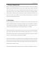
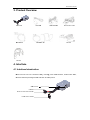
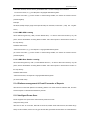
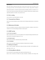
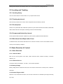
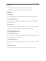
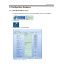
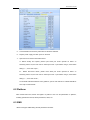
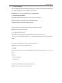
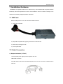
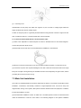
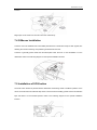
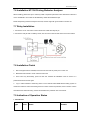
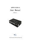
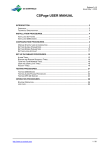
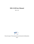
Sinocastel Co.,Ltd MPIIP-619
9 Use
er Man
nual
V
V1.0.0
0
Sinocastel Co.,Ltd Content
1. Product Introduction........................................................................................ - 4 - 2. Disclaimer ................................................................................................... - 4 - 3. Product Overview .......................................................................................... - 5 - 4. Interface ..................................................................................................... - 5 - 4.1 Interface Introduction ................................................................................... - 5 - 4.2 Interface Pin Definition ................................................................................. - 6 - 4.2.1 2*2PIN Multi-function Cable Interface ...................................................... - 6 - 4.2.2 1*4PIN Power Cable Definition ............................................................. - 6 - 5. Function ..................................................................................................... - 6 - 5.1 Highlights ................................................................................................ - 6 - 5.1.1 Easy Installation ................................................................................. - 6 - 5.1.2 GPS Module Integrated ........................................................................ - 6 - 5.1.3 GPS Locating &Tracking ....................................................................... - 6 - 5.1.4 Platform management & E-mail Forwarder of Reports .................................... - 7 - 5.1.5 Intelligent Power Save ......................................................................... - 7 - 5.1.6 Car Locating ..................................................................................... - 8 - 5.1.7 Command from Platform ....................................................................... - 8 - 5.1.8 Maintenance Reminder ........................................................................ - 8 - 5.1.9 OBD Function ................................................................................... - 8 - 5.1.10 Driving Behavior Monitor ..................................................................... - 8 - 5.2 Locating and Tracking .................................................................................. - 9 - 5.2.1 Locating Query .................................................................................. - 9 - 5.2.2 Tracking by interval ............................................................................. - 9 - 5.2.3 Fixed Upload .................................................................................... - 9 - 5.2.4 Compressed Upload by Interval .............................................................. - 9 - 5.2.5 Blind Area Store/Report after Event .......................................................... - 9 - 5.3 State Detection & Control ............................................................................. - 9 - 5.3.1 State Detection .................................................................................. - 9 - 5.4 Alarm .................................................................................................... - 10 - 5.4.1 SMS Alarm ...................................................................................... - 10 - 5.4.2 SOS Emergency Alarm ....................................................................... - 10 - 5.4.3 Other Alarm ..................................................................................... - 10 - 5.5 Terminal Maintenance ................................................................................. - 10 - 5.5.1 CASTELECOM PC Tool ...................................................................... - 10 - 5.5.2 Remote Maintenance .......................................................................... - 10 - 5.5.3 SMS Maintenance ............................................................................. - 10 - 6. Configuration Guidance .................................................................................. - 11 - 6.1 PC Tool .................................................................................................. - 11 - 6.2 Platform ................................................................................................. - 12 - 6.3 SMS ..................................................................................................... - 12 - 7. Installation Guidance ..................................................................................... - 14 - 7.1 SIM Card ................................................................................................ - 14 - 7.2 Cable Connection ...................................................................................... - 14 - 7.3 Main Unit Installation .................................................................................. - 16 - 7.4 G-Mouse Installation .................................................................................. - 17 - Sinocastel Co.,Ltd 7.5 Installation of SOS button ............................................................................ - 17 - 7.6 Installation HT-196 Driving Behavior Analyzer ..................................................... - 18 - 7.7 Relay Installation ...................................................................................... - 18 - 7.8 Installation Finish ...................................................................................... - 18 - 7.9 Indication of Operation Status ....................................................................... - 18 - 8. Packing List ................................................................................................ - 20 - 8.1 Standard ................................................................................................ - 20 - 8.2 Optional ................................................................................................. - 20 - 9. Technical Specification ................................................................................... - 20 - 10. Care and Maintenance ................................................................................... - 22 - 11. General Trouble Shooting ................................................................................ - 23 - 12. Claim ........................................................................................................ - 25 - Sinocastel Co.,Ltd 1. Product Introduction
MPIP-619 mobile terminal integrates internationally leading technologies of GPS, GSM, intelligent
automatic control and anti-theft alarming. It is able to monitor position, safety, operation and technical
status of moving target 24 hours a day, and it provides real-time tracking, fleet management ,anti-theft of
vehicle, asking for help in case of accident, fault repair, data checking, fuel consumption statistics,
mileage statistics, maintenance reminder, driving behavior analyzer, RFID attendance statistics, SMS
alarm, Geo-fence alarm, easy installation, total fuel consumption read, fault alarm read, engine speed
alarm read and temperature alarm read, etc.
2. Disclaimer
MPIP-619 mobile terminal is developed on GPS applied technology of United States. Since its GPS
receiver must always keep directly communicating with satellite in the course of operation, the equipment
may be affected when it operates in electromagnetic shielded areas or when the carrier (such as a
vehicle) is under some shelters like indoor area, underground parking lot or footbridge;
MPIP-619 mobile terminal is a radio communication device. The product shall be as far away as possible
from areas that might cause explosion like fuel warehouses, chemical plants, and so on. The product
may be affected in places sensitive to external radio-frequency signals, such as gas stations, hospitals,
schools, etc, where radio frequency suppressors may be installed;
Because data communication is conducted between system adopting GSM technology and monitoring
center, user must use SIM cards of public communication network operators whose GPRS signal cover
the area where car runs. Besides, the SIM card shall always contain sufficient value. Please do not use
SIM cards subject to limitation of regions;
Please use accessories provided by original manufacturer to guarantee normal operation of the product.
Sinocastel Co.,Ltd C
3. Produc
ct Overv
view
Main Unit
GMOUSE
E
S
SOS
Button
GSM Antenn
na
Installattion Kit
Multi-function Cable
HT-196
HT-195
4. Interfac
ce
4.1 Interfac
ce Introduction
M
MPIP-619
main unit has 4 interfaces tottally, including
g power cable
e interface, m
multi-function cable,
c
G
G-mouse
interrface (RS-232)) and SIM Carrd slot. As belo
ow picture:
SIM
M Card slot G‐Mou
use Multi‐functio
on cable interfacce Poweer cable Interfaace Sinocastel Co.,Ltd 4.2 Interface Pin Definition
4.2.1
Overview
4.2.2
Overview
2*2PIN Multi-function Cable Interface
Pin
Function
Color
Tag
1
Remote power cut off
White
RELAY
2
5v output
Orange
SOS
3
Input IO/Ground
Black
4
ACC
Green
ACC
1*4PIN Power Cable Definition
Pin
Function
Color
Tag
2
Power(-)
Black
POWER(-)
3
Power(+)
Red
POWER (+)
1
4
5. Function
5.1 Highlights
5.1.1 Easy Installation
Power supplied by OBD port, device doesn’t need external power cable.OBD unit supports plug and play
and to adapt 12VDC and 24VDC automatically.
5.1.2 GPS Module Integrated
The terminal can get locations globally with GPS technology.
5.1.3 GPS Locating &Tracking
5.1.3.1 Phone Call Locating
Dial the SIM card number by cell phone, and then cut it off before it is received. The initiator will receive a
feedback SMS with location information, click map link to check device’s location on the map directly.
Sinocastel Co.,Ltd If the call is received, the user will not get feedback SMS. Location message format is below:
“Car license number, xx, yy, A/V! Map link? Language& latitude& longitude”
(xx means CSQ value, yy means number of valid locating satellite, A/V means the location result is
positive/negative)
Example:
K576N,26,9,A!http://maps.google.com/maps?hl=en&q=22.7643750,114.3974383 ( Map link English:
hl=en)
5.1.3.2 SMS GPS Locating
Send “SMS Encryption key, LBG(Location Based GPS)” to device’s SIM card number by any cell
phone ,device will feedback a locating SMS to initiator. User click map link to check device’s location on
the map directly.
Feedback SMS format:
“Car license number ,xx, yy, A/V! Map link? Language& latitude& longitude”
(xx means CSQ value, yy means number of valid locating satellite, A/V means the location result is
positive/negative)
5.1.3.3 SMS Base Station Locating
Send “SMS Encryption key, LBS(Location Based Services)” to device’s SIM card number by any cell
phone ,device will feedback a locating SMS to initiator. User click map link to check device’s location on
the map directly.
Feedback SMS format:
“Car license number, xx! Map link? Language& latitude& longitude”
(xx means CSQ value)
5.1.4 Platform management & E-mail Forwarder of Reports
After device connects with platform successfully, platform can check and store real-time data, and then
send the reports to referred email address by interval.
5.1.5 Intelligent Power Save
Device supports none power-save mode and half power-save mode.
Half power-saving mode
After ACC is OFF for 5 minutes, GPS will be turned off, GPRS will be disconnected, and GSM will go
sleep. On this condition, device can only get call and SMS, upload last location data. ALL external device
Sinocastel Co.,Ltd will be turned off.
When device goes into half power-saving mode, it will be woke up when: ACC on, Door open, Cut off
power supply, SOS alarm, Abnormal Temperature, Abnormal Fuel, called, unplug of OBD. Then GPS &
GPRS will be powered on, terminal will upload alarm data immediately (whatever it is located or not, if
can’t be located, device will upload last valid location), meanwhile it will keep online working state and
upload data (whatever it is located or not) until next ACC off.
5.1.6 Car Locating
User can locate a car by internet platform or PC client.
5.1.7 Command from Platform
Platform can send text message to device via GPRS, the text message will be showed on LCD screen&
handset.
5.1.8 Maintenance Reminder
User can set maintenance reminder on platform according to time period or mileage, to remind user to
maintain the car once the time/mileage exceeds the number pre-set.
5.1.9 OBD Function
5.1.9.1 Fuel Consumption
When connected with HT-195, main unit will update the fuel consumption binding with GPS data, which
will be showed on the platform. Margin of error:+/-5%.
5.1.9.2 Remaining Oil
When HT-195 is connected, it will read remaining oil data from OBD.
5.1.9.3 Fault Warn
When HT-195 is connected, it will read car’s fault data from OBD and send it to platform.
5.1.9.4 Mileage Consumption
When HT-195 is connected, it will read car’s mileage consumption from OBD. It was calculated by GPS
data. Margin of error:+/-5%.
5.1.10 Driving Behavior Monitor
Device can detect over speed, parking without engine off and fatigue driving, etc;
When HT-196 is connected, it can detect over speed, acceleration, deceleration, lane change, crash,
Sinocastel Co.,Ltd parking without engine off and fatigue driving, etc. HT-196 will get alarm of illegal behavior.
5.2 Locating and Tracking
5.2.1 Locating Query
User can check vehicle’s current location on any computer with network.
5.2.2 Tracking by interval
After receiving command from center, device will upload GPS information by interval.
5.2.3 Fixed Upload
Terminal can upload GPS data, OBD data to platform by time interval without times limited, default OBD
data includes total fuel consumption, remaining oil volume and total mileage.
5.2.4 Compressed Upload by Interval
Device uploads GPS information to platform by interval, after it gathered 8 GPS &OBD data
5.2.5 Blind Area Store/Report after Event
In GSM blind area, GPS data & OBD data can be stored and resend to server when GPRS service is
woke up. Stock capacity is 3000pcs.
5.3 State Detection & Control
5.3.1 State Detection
5.3.1.1 Vehicle Status
Main unit can check ignition on/off status, OBD connection status, external accessory connection
detection, etc.
5.3.1.2 External Device
Connection status of G-MOUSE,HT-196R,HT-195 will be uploaded.
5.3.2 Battery Voltage
Battery voltage data is contained in GPS data, if the value is lower than the number pre-set, it will warn
with alarm.
5.3.3 Remote Engine On/Off
When the car is confirmed to be stolen, user can send command to cut off/wake up the engine remotely
by 2 ways:
Sinocastel Co.,Ltd a)
Platform GPRS
b)
SMS
Cut Off: Send “SMS Encryption Key, engine off” by any cell phone to device;
Wake Up: Send “SMS Encryption Key, engine on” by any cell phone to device;
5.4 Alarm
5.4.1 SMS Alarm
Device sends important alarm (SOS, low voltage, power cable cut off) to preset cell phone via SMS.
5.4.2 SOS Emergency Alarm
In case of emergency in car, terminal will send emergency alarm to center after user press SOS button
for more than 3 seconds.
5.4.3 Other Alarm
Power cable cut off, low voltage, engine on/off, GPS Failure, over speed, crash, accelerate, decelerate,
lane change, park with engine on, high RPM, high water temperature, fatigue driving.
5.5 Terminal Maintenance
5.5.1 CASTELECOM PC Tool
User can read and modify all parameters, and update the firmware by CASTELECOM PC Tool. See
details on chapter 6: Configuration Guidance.
5.5.2 Remote Maintenance
User can modify parameters through online platform client. See details on chapter 6: Configuration
Guidance.
5.5.3 SMS Maintenance
User can modify part of parameters via SMS. See details on chapter 6: Configuration Guidance.
Sinocastel Co.,Ltd 6. Configuration Guidance
6.1 CASTELECOM PC Tool
1) Install CASTELECOM PC Tool on PC, click CATELECOM PC Tool.msi to start installation.
2) PCTool Icon.
3) Double click icon to run the software.
4) Choose “Product--->MPIP-619” .
Sinocastel Co.,Ltd 5) Connect MPIP-619 with PC by data cable via G-Mouse interface.
6) Prepare power supply, and then power on terminal.
7) Open Com Port. Please notice below items:
A ) Before modify and update, please open serial port mode. Operate as below: on
“Network_Others” bar, the first order is “Serial port mode(open before using it, close before
exiting it.)”, then click ”Open” ;
B ) Before disconnect device, please close serial port mode. Operate as below: on
“Network_Others” bar, the first order is “Serial port mode(open before using it, close before
exiting it.)”, then click ”Close” ;
To see detail CASTELECOM PC TOOL guidance, open its user manual on CASTELECOM PC
Tool “Help-ÆUser Manual”.
6.2 Platform
After inserted SIM Card, device will register on platform. User can set parameters on platform,
including upload time interval, GPRS parameters, alarm, etc..
6.3 SMS
MPIP-619 support SMS setting several parameters as below:
Sinocastel Co.,Ltd 1) Terminal Language
User can change device’s language between English and Chinese by sending “SMS encryption Key,
EN”, “SMS encryption Key, CN” to terminal by any cell phone.
Feedback: “EN, ok”, “CN, ok” means success, no feedback if fails.
2) Authorized Phone Number
Send SMS “SMS encryption Key, SP, no1, no2, no3” by any cell phone.
If there’s’ no need for any number, user can keep blank in SMS.
To delete all number, send “SMS encryption Key, SP”.
For example: Set first authorized number with SMS “123884,SP, 123456,,”
Feedback ”SP, 123456,,ok” if success.
3) Fixed upload time interval
Send SMS “SMS encryption Key,,SI,fixed upload time interval” by any cell phone.
The units of “fixed upload time interval” is “s”. “fixed upload time interval=0” means stop fixed
upload.
For example: “123884,SI,60” is to set the time interval as 60s.
Feedback “SI,ok” if success. No feedback if fail.
4) GPRS
Send SMS “SMS encryption Key,,SG,DialMode,IP/domain,Port,APN,user,password” by any cell
phone.
DialMode
=0, means domain dial
=1, means IP dial
For example: 123884,SG,0,www.163.com,7888,cmnet,,
Feedback “SG,ok” if success. No feedback if fails.
Sinocastel Co.,Ltd 7. Installation Guidance
!WARNING: The operations below are for reference only. We recommend that the product shall be
installed by technicians specialized in vehicle circuit installation. We are not liable for damage to the
vehicle circuit caused by improper operation of the client.
7.1 SIM Card
Before installing device to car, user should insert SIM Card at first:
1) Open the cover board
2)Keep SIM card upwards and gap inby, then insert it to SIM card slot;
3)Switch the power toggle to “ON”;
4)Cover up the board.
7.2 Cable Connection
a)Simple Installation(HT-195)
HT-195 provides power supply and ACC signal for main unit.
OBD Cable Connection:
Plug OBD cable’s male terminal into OBD diagnostic port in car, then connect the cathode/anode to
main unit.
Sinocastel Co.,Ltd b) Installation without HT-195
1)Cable Check
Please refer to the following instructions to locate the connection positions of functional cables in vehicle.
(1) Power Cord
Power cord position: It is generally located in wiring harness inside the lower baffle plate of the
steering wheel, or inside the door wiring harness of the driver’s seat, or inside the fuse box. It can
also be directly connected with the positive pole of the vehicle battery.
Method of locating: ground one end of the test probe and put the other end on the power cord. The
key is respectively in the position of OFF, ON or ACC, and the LED indicator of the test probe always
lights constantly.
(2) Ground Cord
The ground cord of vehicle generally adopts the mode of grounding.
(3) ACC detection cord (IGN+)
ACC detection cord (IGN+) is the basis to judge whether the vehicle’s engine is on, and it is located
in wiring harness inside the lower baffle plate of steering wheel, or inside the fuse box.
Method of locating: ground one end of the test probe and put the other end on the wire. When the
vehicle key is respectively in the position of ACC, ON or START, the LED indicator of the test probe
illuminates. When the key returns to the position of OFF, the LED indicator of the test probe goes off.
Sinocastel Co.,Ltd (4)
Fuel Pump Cord
Characteristics of fuel pump cord: When the engine is off, the cord has no voltage signal. When the
engine is started, the wire has voltage signal.
Location of fuel pump wire: It is generally located inside the wiring harness of the left or right front door
side, or inside the fuse box, or under the back seat, near the fuel tank.
2)Connection between Multi-function Cord and Power Cable
(1) Refer to the explanation of functional ports as shown in the“MPIP-619 Port Connection Diagram”.
Connect the ports with vehicle circuit;
(2) Please take out the fuse wire in the fuse base before installation to avoid blowout.
(3) All wire’s connection and the part out in air must make insulation protection, to avoid short circuit.
(4) Connection of power cord requires installing the fuse seat in standard accessories within 0.3m length
from joint. Principle of local grounding for the MPIP-619 main unit is adopted by the ground wire, and the
grounding wire must not exceed 1m long.
7.3 Main Unit Installation
(a) Location for installing MPIP-619 should be determined in advance. The location should allow secure
installation, concealment, anti-humidity, avoidance of high-temperature area, and be far away from
magnetic field, air bag, sound system, ABS system and there sensitive electronic equipment. In addition,
it should be installed to conceal.
(b) Recommended installation location for MPIP-619: concealed position inside the decorated board
under the dashboard or under the seat. Refer to the following diagram for the specific installation
Sinocastel Co.,Ltd location:
Magic tape can be used to fix the main unit to the vehicle body.
7.4 G-Mouse Installation
G-mouse cannot be installed under metal baffle plate because it will hinder receipt of GPS signals, thus
affecting the normal monitoring and positioning of MPIP-6189 main unit.
G-mouse is generally placed inside the decorated plate under the front or rear windshield or on the
dashboard. Refer to the following diagram for the specific installation location:
7.5 Installation of SOS button
The SOS button should be placed between dashboard and steering wheel to facilitate operation of the
driver. The SOS button has adhesive tape stuck to its back. When installing, please remove the adhesive
tape and attach it to the intended position. Refer to the following diagram for the specific installation
location:
Sinocastel Co.,Ltd 7.6 Installation HT-196 Driving Behavior Analyzer
When installing, please don’t put it under any metal or explosion prevention metal. We advise to absorb it
on the windshield or fix it under the windshield by double faced adhesive tape.
Please keep driving behavior analyzer horizontal, and the angle with ground shall not exceed 15°.
7.7 Relay Installation
1. Connect the CUT1 control line of the multi-function cable with relay 86 pin.
2. Connect the relay 85 with car battery anode, 87a.30 connect with two side of the ACC line as below:
7.8 Installation Finish
1. After all equipments are installed, insert fuse into fuse base to power port on main unit
2. Meanwhile start vehicle to check if device works well.
3. Once notice any abnormality, power off main unit. Recheck all installation wires or send it to a
professional vehicle service agent.
4. Log on “Client software of monitoring center” or the “Internet-based WEB vehicle tracking system” to
check if the vehicle is online and locating service is normal. If there are problems, refer to Section X of the
User Manual for trouble shooting. Contact local dealer if the problems cannot be solved.
7.9 Indication of Operation Status
1. LED Indicator
Type
Color
Status
Remark
Sinocastel Co.,Ltd LED indicator on SOS
Constantly On: Regular Work
POWER
Red
button
or
main
unit’s
Extinguish: Power off
board
Extinguish: Slumbering or power off;
LED indicator on main
GSM
Blue
Flickering: Log on network successfully
unit’s board
Constant on: log on failed
Extinguish: Slumbering or power off;
LED indicator on main
GPS
Green
Flickering: Locate successfully
unit’s board
Constant on: Searching for signal
GPS
Extinguish: Slumbering or power off;
LED
Flickering: Locate successfully
G-Mouse
indicator
on
indicator
on
indicator
on
Green
Flickering( on 250ms, off 250ms):No ID card or
illegal ID card
RFID
Yellow
On 1s:getting the ID card
LED
HT-196
Constant on: Get ID card
Constant off: in power on 1 minutes, power off or
RFID abnormal power supply
Driving
Yellow
behavior
& Red
Yellow on 3s:normal illegal driving behavior
Red on 3s:serious illegal driving behavior
LED
HT-196
Extinguished: no illegal driving behavior
2. Buzzer:
Tone
Remark
Di (last 500ms):power on
Di (last 500ms):read RFID card
Di- Di (last 100ms, every 100ms):illegal card
Di- Di (last 100ms, every 100ms, 1s ring 1 time): no card read
Di- Di -Di(last 100ms, every 100ms):normal illegal driving behavior
Di- Di -Di -Di-Di (last 100ms, every 100ms):serious illegal driving behavior
Buzzer
HT-196
indicator
on
Sinocastel Co.,Ltd 8. Packing List
8.1 Standard
Standard
Quantity
MPIP-619 Main Unit
1
Power Cable
1
G-mouse
1
CD User Manual (including warranty card)
1
Installation Accessories(including fuse、 sticker、 cable tie)
1
8.2 Optional
Optional
Remark
Quantity
USB Data Cable
1
Multi-function cable
1
SOS button
1
Relay
1
HT-195(16P/9P/6P Optional)
1
HT-196(RFID Optional)
G-MOUSE Alternative
9. Technical Specification
Item
Description
Dimension
75mm(L)*48mm(W)*20mm(H)
Weight
80g
Protection Level
IP54
Working Voltage
9V-36V DC
Battery
3.7V/300mAH Lithium battery
Stand by current
40mA
Max working current
<[email protected](not including accessory)
TX/RX Current
<150 [email protected](not including accessory)
ACC OFF current
<90mA@12V/24V(not including accessory)
1
Sinocastel Co.,Ltd Extinguish Current
<20mA@12V/24V(not including accessory)
Working Temperature
-30℃~+70℃
Stock Temperature
-40℃~+85℃
Humidity
5%~95%(No frost)
GSM Frequency
GSM 850/900/1800/1900MHz
Data transmission
GPRS
Locate
GPS
GPS Chip
SIRF 3
Locate Speed
≤0.1m/s
Accuracy
GPS Sensitivity
-159dB
Locate Accuracy
≤15m
SOS
LED Indicator/SOS Button function reuse
Button/LED
Indicator
Certificate
FCC:CE: E-Mark
HT-195
OBD passenger car protocol:
SAE J1850 PWM (10.4 kbaud);SAE J1850 VPW (41.6 kbaud)
ISO 9141-2 (5 baud init);ISO 14230-4 (5 buad init)
ISO 14230-4 (fast init);ISO 15765-4 CAN (11 bit ID, 500 kbaud)
ISO 15765-4 CAN (29 bit ID, 500 kbaud);
ISO 15765-4 CAN (11 bit ID, 250 kbaud);
ISO 15765-4 CAN (29 bit ID, 250 kbaud);
OBD commercial car protocol:
SAE J1939 CAN (29 bit ID, 250 kbaud)
SAE J1587/J1708 (9.6 kbaud)
HT-196R(Optional)
RFID attendance and driving behavior management, RFID frequency 125KHz
I/O port
1 digital/analog input
1 digital output(engine cut)
1 SOS input
Note: above current is read under 12V power circumstance, actual data would be a little different under
local circumstance.
Sinocastel Co.,Ltd 10.
Care and Maintenance
To ensure proper use and extend service life of device, following items should be paid attention to in the
course of installation, use, care and maintenance:
1) The voltage range of normal power supply for mobile terminal is DC 9V—36V, and recommended
operating voltage is12V or 24V. Prior to installation, user shall make sure the power supply is in the range
aforesaid.
2) When the in-Vehicle terminal is powered on, do not plug in or pullout the antenna or remove SIM card
to avoid damage to the in-Vehicle terminal and SIM card.
3) The connection socket of the in-Vehicle terminal shall avoid direct contact with conductive body,
otherwise it may result in short circuit and danger.
4) Do not use mobile terminal in a dusty environment. When washing the vehicle, try to prevent the
terminal from being soaked or showered which will damage the terminal.
5) Keep using the mobile terminal in required temperature. The equipment may be damaged when user
operate too long in the environment where the temperature is above 85℃ or lower than -40℃.
6) When vehicle is inside building, tunnel or within a shielded area, receiving of GPS and GSM signals
will be affected. After vehicle moves out of the area mentioned above, it will automatically resume
7) Main unit has built-in spare battery which will not be activated and begin working untill the equipment is
used for first time with external power. After the battery is activated, the power supply will automatically
switch to built-in battery, which can last for about 10 hours (calculated based on that the terminal data
transmits 5 minutes per time).
8) Terminal can only use accessories designated or recognized by CASTEL. Unauthorized accessories
may damage the device.
9) If abnormality occurs to the terminal equipment or its accessories, which leads to failure of normal
Sinocastel Co.,Ltd operation, please contact the manufacturer or local dealer.
11.
General Trouble Shooting
Trouble
Possible Cause and Solution
Terminal can’ log online
1. Fuse of power cord is burned so that there is no power supply.
Solution: change fuses.
2. Improper setup of parameters
Solution: check APN parameters and reset.
3. Insufficient value of SIM card or non-support of GPRS function.
Solution: reconfirm the SIM card function.
4. Improper connection of GSM antenna and weak signal.
Solution: check GSM antenna.
5. Failure of MPIP-619 main unit
Solution: send it to designated maintenance center for repair.
Terminal can’t be located
1. GPS antenna is shielded by metal shielding object.
Solution: remove the metal shielding object or reinstall G-mouse at another
place.
2. G-mouse failure.
Solution: return it to the designated maintenance center for repair.
3. Failure of the MPIP-619 main unit.
Solution: send it to the designated maintenance center for repair.
Power cut-off alarm
1. Fuse of the power source is burned.
Solution: change fuses.
2. The power cord is improperly connected with the ACC end.
Solution: check the connection and reconnect it to the common power cord.
Can’t upload emergency
1. The SOS button has not been connected.
Solution: check the SOS button.
alarm
2. MPIP-619 main unit won’t come online, and the alarm information fails to
be reported.
Solution: analyze why the MPIP-619 main unit won’t come online.
3. Failure of the MPIP-619 main unit
Solution: send it to the designated maintenance center for repair.
Sinocastel Co.,Ltd Warranty Card
User Name:
Phone No.:
Address:
Post Code:
Purchase date:
Device serial No.:
Agency and phone No.
Remark:
Please keep this card properly for better service. Please see service details as below.
Agency (Stamp):
Repair Record
Device Model:
Troubles and repair record
Date
Sign(Maintainer)
Trouble
Record
Note: Agency should fill this card completely before repair.
Sign(User)
Sinocastel Co.,Ltd 12.
Claim
Without written authorization of CHINA AEROSPACE TELECOMMUNICATIONS LTD., any kind of copy,
transmission, dispatching or saving of this file is prohibited.
CHINA AEROSPACE TELECOMMUNICATIONS LTD. keeps the rights of reservation and modification
without any notification in advance. Receiving and operation time would be affected by SIM card, network
and using circumstance of different device. And we don’t take responsibility of data losing and income
wastage, or any special, occasion, and indirection reason.
This file is based on “local” situation. In spite of relative law, explicit or hinting data including (but no
limited in) hinting selling data, is no connection with accuracy and reliability.
Copy right reserved
Sinocastel Co.,Ltd
5F,BLDG5,Shenzhen Software Park, Gaoxin, C.,3rd Road,
Nanshan District, Shenzhen,China 518057Nanshan District,
Shenzhen,China 518057