1
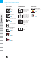
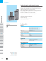
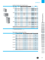
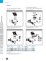
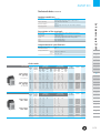
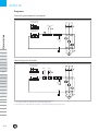
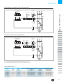
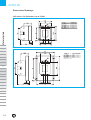
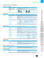
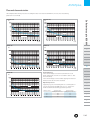
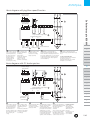
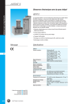
GE Consumer & Industrial
Power Protection
Control and Automation
For industrial applications
Everything is under control
GE imagination at work
Control and Automation
A
C
D
Auxiliary contactors and
Plug-in relays
Contactors and
Thermal overload relays
Motorstarters
Series PRC - Plug-in relays
Series M - Minicontactors
Coordination
Miniature plug-in relays
Standard 8-11 pin plug-in
relays
3 and 4P (4NO, 2NO+2NC,
4NC) 6,9 and 12A (AC-3)
20A (AC-1)
Control circuit AC and DC
! A.2
! C.2
Series M - Auxiliary minicontactors
Extended index
lth = 16A
! A.16
Series RL - Auxiliary contactors
lth = 20A
! A.22
Series CL - Contactors
3 and 4P (4NO, 2NO+2NC)
9 to 105A (AC-3) 25 to 140A
(AC-1) AC, DC and with
electronic module
! C.10
Series CK - Contactors
3 and 4P (4NO) 150 to 825A
(AC-3) 200 to 1250A (AC-1)
AC, DC and with electronic
module
! C.18
Series MTO - Thermal overload relays
For minicontactors series M
from 0.11 to 14A
B
Motor protection devices
Series SFK Motor protection circuit breaker
Thermal and magnetic protection of AC and DC motors
Setting ranges from 0.1
to 25A
! B.2
Surion - Manual motor starter
Thermal and magnetic protection - Magnetic protection
! C.60
Series RT - Thermal overload relays
For contactors series CL and
CK from 0.16 to 850A
Class 10A, 10, 20, 30
! C.62
Series CSC Contactors for capacitors switching
! D.2
Direct-on-line starters
Series M: 6 to 12A (AC-3)
Series CL: 9 to 105A (AC-3)
Series CK: 150 to 825A (AC-3)
! D.18
Reversing starters
Series M: 6 to 12A (AC-3)
Series CL: 9 to 105A (AC-3)
Series CK: 150 to 825A (AC-3)
! D.20
Star-delta starters
Series CL
Series CK
! D.22
ASTAT S - Soft starter
Small soft starter with
integral by-pass
! D.66
ASTAT SD - Soft starter
Soft starter for 3ph AC motors up to 850 kW
Setting ranges from 0.1
to 63A
! B.8
Link modules for mechanical
and electrical connection of
the manual motor starter
and the M/CL contactor
ranges
! C.74
Series 390.R - Clapper contactors
! D.72
ASTATplus - Soft starter
Solid state soft starter for
3ph AC motors up to 850 kW
! C.80
2
! D.78
Control and Automation
E
F
Control and signalling units
Electronic relays
Series P9 - Panel mounting Units Ø 22 mm
Series 101 - Palm push-buttons
Series DM - Single voltage relays
22.5mm module
Direct supply voltage
With transformer
! E.10
Series P9 - Base mounting
! E.82
Series IP - Foot switches
! F.3
Series NMV - Multivoltage relays
! E.25
Series P9 - Push-button stations
! E.84
Safety foot switches
Extended index
22.5mm module
Direct supply voltage (24240V AC/DC)
With transformer
! F.4
Series D - Single voltage relays
45mm module
Direct supply voltage
With transformer
! E.28
Series P9 - Equipped boxes
! E.86
Series 105 - Signalling devices
! F.6
Liquid level detectors
45 mm module
With transformer
DIN mounting
! E.31
Series P9 - Common accessories
! E.87
! F.7
Earth leakage relays
45 mm module
Direct supply voltage
With transformer
! E.34
Series 077 - Units Ø 30 mm
! F.8
Protection relays
45 mm module
Direct supply voltage
With transformer
! E.48
Series NLT - Light towers
! F.9
Detection relays
Direct supply voltage
With transformer
! E.76
! F.10
Control and protection relays
! F.11
3
Control and Automation
G
H
I
Limit switches
Speed drive units
Main switches
Series IS and IM
VAT20
Series ML - standard programme
Metal and Thermoplastic
EN 50041
Positive opening
Single-phase or three-phase
digital inverters for controlling the speed of threephase induction AC motors
from 0.2 to 2.2 kW
! G.2
Series IUG and IUC
Extended index
Thermoplastic EN 50047
Positive opening
! H.2
Series ML - enclosed switches
From 0.4 to 2.2kW at 200V,
single phase power supply
From 0.4 to 7.5kW at 200V,
three phase power supply
From 0.75 to 11kW at 400V,
three phase power supply
Series IZ
! H.8
Thermoplastic miniature
VAT2000
Series 114FCT
Three pole limit switches
Thermoplastic
Positive opening
! G.8
Three phase variable speed
drives for AC motors 220240V or 380-480V power
source
0.4 to 315kW in constant
torque and up to 370kW in
variable torque applications
! H.14
AV300i - Adjustable frequency
flux vector drive
Series 115 - Pressure switches
Bellows type
Piston type
! H.38
! G.16
Safety switches
! G.22
Pull rope switches
! G.26
4
! I.4
VAT200
! G.4
! G.6
Main switches and Emergency-stop switches for
machinery
! I.7
ASTAT S
Small soft starter with integral by-pass
ASTAT S is compact, easy to operate soft starter, designed for use with
standard 3-phase squirrel cage motors. It provides an advanced method of
reducing current during motor starting and stopping.
ASTAT S will start supplying a reduced voltage to the motor, increasing up to
the rated voltage, so avoiding, high currents and generating soft
starting and stopping.
The motor has to be able to start in a reduced voltage.
Motorstarters
• Solid soft starter for standard 3ph AC motors up to 30kW
at 400V AC
• Voltage ratings up to 600V
• Two phase control with integral by-pass
• Compact, small case
• DIN rail mounting. Optional from 31A
• Start and soft stop features
A
Marking
Technical data
Ratings
Voltage ratings
B
Frequency range
Load
C
3ph AC systems
220/230V (+10%, -15%) for units QA02P_ _ _ S
380/415V (+10%, -15%) for units QA12P _ _ _ S
480/500V (+10%, -15%) for units QA22P _ _ _ S
575/600V (+10%, -15%) for units QA32P _ _ _ S
50/60Hz (±5%)
3ph, AC standard motors
Control specifications
D
Ramp up
Ramp down
Initial voltage
Starting torque
E
0,5 - 10 s
0,5 - 10 s
0 - 80% Un
0 - 64% Tn
I/O control
F
Inputs
Outputs
G
Ambient conditions
H
Operating temperature
Storage temperature
Relative humidity
Max. altitude
Protection degree
I
X
Order codes !
Diagrams !
Function !
Dimensions !
D.66
page D.67
page D.68
page D.69
page D.70
one input for Start/Stop
one output for «End of Ramp» signal
for ratings 31, 44, 58A
0 to 40ºC. Up to 60ºC derating by 1,2% per ºC
-20 to 70ºC
up to 80%, without condensation
up to 1000m.
Above this derate by 5% each 100m
IP20
ASTAT S
Small soft starter with integral by-pass
Input Current
voltage rating (2)
V CA
A
220
8
17
22
31
44
58
Maximum
current
A
28
60
77
110
150
200
220/230V
kW / Hp
1.5 / 2
4 / 5.5
5.5 / 7.5
7.5 / 10
11 / 15
15 / 20
Maximum motor power (1)
380/415V 480/500V 575/600V
kW / Hp kW / Hp kW / Hp
-
Cat. No.
Ref. no. Pack
QA02P008S
QA02P017S
QA02P022S
QA02P031S
QA02P044S
QA02P058S
120881
120882
120883
120884
120885
120886
1
1
1
1
1
1
8
17
22
31
44
58
28
60
77
110
150
200
-
4 / 5.5
7.5 / 10
11 / 15
15 / 20
22 / 30
30 / 40
-
-
QA12P008S
QA12P017S
QA12P022S
QA12P031S
QA12P044S
QA12P058S
120892
120893
120894
120895
120896
120897
1
1
1
1
1
1
500
8
17
22
31
44
58
28
60
77
110
150
200
-
-
5.5 / 7.5
11 / 15
15 / 20
22 / 30
30 / 40
45 / 60
-
QA22P008S
QA22P017S
QA22P022S
QA22P031S
QA22P044S
QA22P058S
120898
120899
120900
120901
120902
120903
1
1
1
1
1
1
600
8
17
22
31
44
58
28
60
77
110
150
200
-
-
-
7.5 / 10
15 / 20
22 / 30
30 / 40
37 / 50
55 / 75
QA32P008S
QA32P017S
QA32P022S
QA32P031S
QA32P044S
QA32P058S
120904
120905
120906
120907
120908
120909
1
1
1
1
1
1
QAOPTDIN
120910
1
Accessory
DIN rail mounting kit for types 31A, 44A and 58A
(1) Ratings for standard 4-poles AC motors
(2) See Operations/hour in table below
Cycles/hour includes both soft start and soft stop
QA_2P008S
QA_2P017S
QA_2P022S
QA_2P031S
QA_2P044S
QA_2P058S
A
B
C
Time between rampings Start/Stop
Starting
Ramp 1 sec.
current
8
7
16
16
24
26
28 (*)
32
17
7
34
16
51
26
60 (*)
32
22
7
44
16
66
26
77 (*)
32
31
4
62
8
93
12
110 (*)
15
44
4
88
8
132
12
155(*)
15
58
4
116
8
174
12
200 (*)
15
(*) Maximum starting current at all
Small soft starters
400
Ramp 2 sec.
Ramp 5 sec.
Ramp 10 sec.
15
33
51
62
15
33
51
62
15
33
51
62
8
15
24
31
8
15
24
31
8
15
24
31
35
77
125
155
35
77
125
155
35
77
125
155
20
38
62
80
20
38
62
80
20
38
62
80
70
155
250
70
155
250
70
155
250
40
76
124
40
76
124
40
76
124
-
D
E
F
G
H
I
X
D.67
ASTAT S
Diagrams
Control by push-buttons,
line contactor and thermal overload
relay (soft start)
Motorstarters
Control by permanent command
(soft start and stop)
start/stop
A
B
Control by push-buttons and line
contactor (soft start)
Forward/reverse control by
push-buttons (3)
C
D
E
F
G
H
Motor power
380/415V
kW
Hp
I
X
4
7.5
11
15
22
30
Q1
QA12P008
QA12P017
QA12P022
QA12P031
QA12P044
QA12P058
GPS1B*AK
GPS1B*AN
GPS1B*AP
GPS1B*AR
GPS2B*AT
GPS2B*AU
Q2
KM1
F1-F2
S1-S2-S3
Contactor
Q3
Thermal
overload relay
Am fuses
10
25
32
40
63
80
CL25A
CL25A
CL25A
CL04A
CL06A
CL07A
RT A 1N
RT A 1S
RT A 1T
RT A 1V
RT A 2F
RT A 2H
-
P9-P3
P9-P3
P9-P3
P9-P3
P9-P3
P9-P3
Coordination type 2
(1)
(2)
(3)
(4)
D.68
5.5
10
15
20
30
40
ASTAT S
Use dry contact only.
End of Ramp output relay (only types 31A, 44A and 58A.
Forward/Reverse operation must be done when motor is not rotating.
Ground terminal only for types 31A, 44A and 58A.
ASTAT S
Performances
Direct-on-line start
ASTAT S soft start
DOL
Current
Speed
Speed
Time
Time
Direct-on-line stop
RAMP DOWN 0.5s
B
C
D
Current
Current
Voltage
Voltage
A
ASTAT S soft stop
DOL
Small soft starters
Current
Voltage
Voltage
Uo=0.5Un, To=25Tn, RAMP UP 0.9s
Speed
Speed
E
Time
F
Time
G
H
I
X
D.69
ASTAT S
Dimensional drawings
Small soft starter with integral by-pass
TYPE
Weight (kg)
QA_2P017S
0.610
QA_2P022S
0.650
QA32P008S
0.650
Motorstarters
TYPE
Weight (kg)
QA12P008S
0.470
QA22P008S
0.470
Dimensions in mm
Dimensions in mm
TYPE
QA_2P031S
QA_2P044S
QA_2P058S
A
Weight (kg)
1.370
1.400
1.400
B
2
C
2
D
E
F
G
H
I
X
Dimensions in mm
D.70
ASTAT SD
Soft starters for 3ph motors up to 20 kW
Solid state soft starter for 3ph AC motors up to 20kW
Working voltage up to 500VAC
With built-in analogue control panel
Three phase - full wave control (6 thyristors)
Excellent basic functions
Motorstarters
•
•
•
•
•
A
Analogue control panel
Technical data
Ratings
3ph AC systems
B
Frequency range
C
up to 440V, + 10%, - 15% for types QS1_NA
up to 500V, + 10%, - 15% for types QS2_NA
49 - 62 Hz
Control specifications
Control system
Initial voltage (pedestal)
Starting torque
Kick start
Motor current (Im)
Current limitation
Acceleration ramp time
Energy savings
Override
Soft stop time
D
E
F
Digital system with microcontroller. Starting ramp with
progressive increase in voltage and current limitation
40% - 90% Un
15% - 80% Mdir.start
90% Un (80% Mdir.start), 400ms
0.5 to 1 Ir (nominal ASTAT)
2 to 5 x Ir
0.5 to 60 s
Output voltage reduction according to power factor
Fixed output voltage permanently equal to supply voltage
Max. 2 x t acceleration time
Operation
External control
Acceleration phase
Permanent phase (choice)
Stop phase (choice)
G
H
Start - Stop
Adjustable time
Energy savings / Override
Power cutt-off / Ramp
Inputs / Outputs
Input
Output
I
Two optical couplings for Start/Stop
One relay either Run or End of ramp (1NO)
Protections
X
Order codes ! page D.73
Diagrams ! page D.74
Dimensions ! page D.76
D.72
D.72
Current limit
Loss on input phase
Thyristor short-circuit
Loss on output phase
Supply frequency error
Error (CPU)
Adjustable from 2 to 5 Ir
Trip at 3 sec.
Trip at 200 ms
Trip at 3 sec.
Will not start if f < 4a8Hz or f > 62Hz
60ms
ASTAT SD
Technical data (continued)
Ambient conditions
Temperature
Relative humidity
Maximum altitude
Mounting position
Soft starters up to 20 kW
0 to +55ºC
(derate output current by 1.5% / ºC above 45ºC)
95% without condensation
3000 m
(derate output current by 1% / 100 m above 1000 m)
Vertical
Description of the terminals
1L1, 3L2, 5L3
2T1, 4T2, 6T3
A1/A2, B1/B2
11, 14
1, 57
2, 57
Power supply (max. 440V or 500V depending type)
Outputs to motor
Command supply inputsa (110/120V - 220/240V AC)
Internal relay output Run / End of ramp (1NO)
Run command input
Stop command input
Output contacts specifications
Maximum usage voltage
Thermal current Ith
Usage specifications
AC15
DC15
380V CA
8A
220V / 3A - 380V / 1A
Max. 30V / 3.5A
A
B
Order codes
IEC ratings
Light duty
Current Maximum
(3 x Ir, 30sec.)
rating starting
Ir
current 220V 380V 440V 480V
240V 415V
500V
A
A
kW kW
kW
kW
5
25
1.1
2.2
2.2
Input voltage
9
45
2.2
4
4
220 - 440 VCA
12
60
3
5.5
6.3
+ 10%, -15%
16
80
4
7.5
7.5
48 < f (Hz)< 62
22
110
5.5
11
11
34
170
7.5
15
18.5
Input voltage
220 - 500 VCA
+ 10%, -15%
48 < f (Hz)< 62
UL ratings
Input voltage
200 - 230 V
Input voltage
200 - 460 V
5
9
12
16
22
34
25
45
60
80
110
170
1.1
2.2
3
4
5.5
7.5
2.2
4
5.5
7.5
10
15
2.2
4
6.3
7.5
11
18.5
Light duty
Current Maximum
(3 x Ir, 30sec.)
rating starting
Ir
current 200V 230V 460V
A
A
Hp
Hp
Hp
5
25
1
1
9
45
2
2
12
60
3
3
16
80
3
5
22
110
5
7.5
34
170
10
10
5
9
12
16
22
34
25
45
60
80
110
170
1
2
3
3
5
10
1
2
3
5
7.5
10
3
5
7.5
10
15
25
3
5.5
7.5
10
13
20
Heavy duty
(4.5 x Ir, 30sec.)
220V
240V
kW
1.1
2.2
3
3.7
5.5
7.5
380V
415V
kW
2.2
4
5.5
6.3
11
15
1.1
2.2
3
3.7
5.5
7.5
2.2
4
5.5
6.3
10
15
440V 480V
500V
kW kW
2.2
4
6.3
7.5
11
17
2.2
4
6.3
7.5
11
15
Heavy duty
(4.5 x Ir, 30sec.)
200V
Hp
1
2
3
3
5
7.5
230V
Hp
1
2
3
5
7.5
7.5
460V
Hp
1
2
3
3
5
7.5
1
2
3
5
7.5
7.5
3
5
7.5
10
15
20
3
5.5
7.5
10
13
20
Cooling
convection
Cat. No.
Ref. no.
Natural
Natural
Natural
Natural
Natural
Natural
QS1BNA
QS1DNA
QS1FNA
QS1GNA
QS1HNA
QS1INA
120460
120462
120464
120466
120468
120470
Natural
Natural
Natural
Natural
Natural
Natural
QS2BNA
QS2DNA
QS2FNA
QS2GNA
QS2HNA
QS2INA
120461
120463
120465
120467
120469
120471
Cooling
convection
Cat. No.
Ref. no
Natural
Natural
Natural
Natural
Natural
Natural
QS1BNA
QS1DNA
QS1FNA
QS1GNA
QS1HNA
QS1INA
120460
120462
120464
120466
120468
120470
Natural
Natural
Natural
Natural
Natural
Natural
QS2BNA
QS2DNA
QS2FNA
QS2GNA
QS2HNA
QS2INA
120461
120463
120465
120467
120469
120471
C
D
E
F
G
H
I
X
D.73
D.73
ASTAT SD
Diagrams
Control by permanent command
Control voltage
110/120V AC
Start / Stop
Motorstarters
Control voltage
220/240V AC
(1)
(2)
A
B
C
Control by push-buttons
Control voltage
110/120V AC
Start
D
Stop
Control voltage
220/240V AC
E
(1)
F
G
(2)
H
I
X
D.74
D.74
(1) These contacts allow for direct action on contactors up to type CL10 at 220 AC.
See Usage specifications to determine the necessity of an auxiliary relay.
(2) The ASTAT SD has no overload function, so always use an external overload relay to protect the motor
ASTAT SD
Permanent command with line contactor
Control voltage
110/120V AC
Control
voltage
Start / Stop
Soft starters up to 20 kW
Control voltage
220/240V AC
(1)
(2)
A
Pulse function with line contactor
Control voltage
110/120V CA
B
Control
voltage
Start
Stop
C
Control voltage
220/240V CA
D
E
(1)
F
G
(2)
H
(1) These contacts allow for direct action on contactors up to type CL10 at 220 AC.
See Usage specifications to determine the necessity of an auxiliary relay.
(2): Use thermal relay if required by local rules, selecting it according to motor current
I
Data power circuit
ASTAT SD
QS _ BNA
QS _ DNA
QS _ FNA
QS _ GNA
QS _ HNA
QS _ I NA
Total
losses
W
17
31
37
49
75
86
Contactor
DC1
Type
CL00
CL00
CL01
CL02
CL04
CL45
aM Fuses
A
12
16
20
25
32
63
Jean Müller
Type
S00C+/üF01/32A/690V
S00C+/üF01/32A/690V
S00C+/üF01/40A/690V
S00C+/üF01/50A/690V
S00C+/üF01/80A/690V
S1ü01/110/100A/690V
Semiconductor fuses
Jean Müller
Ref. No.
R5082953
R5082953
R5083453
R5083553
R5084153
R1084321
Typower Silca 680V ~
Bussmann Type
Size = 00, In = 32A
Size = 00, In = 32A
Size = 00, In = 40A
Size = 00, In = 50A
Size = 00, In = 80A
Size = 00, In = 100A
X
Coordination type 1
D.75
D.75
ASTAT SD
Dimensional drawings
Soft starters for 3ph motors up to 20 kW
.
TYPE
A
Weight (kg)
QS _ BNA
QS _ DNA
QS _ FNA
150
150
180
2.1
2.1
2.2
QS _ GNA 180
2.2
.
Motorstarters
Dimensions in mm
.
.
A
.
TYPE
B
A
Dimensions in mm
C
.
D
E
F
.
G
H
I
X
D.76
D.76
B
QS _ HNA 200 160
QS _ DNA 250 200
.
Weight (kg)
2.9
3.4
ASTATplus
Soft starters for 3ph motors up to 850 kW
Solid state soft starter for 3ph AC motors up to 850 kW
Three pase - full wave control (6 thyristors)
Working voltage up to 500V
Built-in digital operation control panel
Built-in ASCII and Modbus RTU communications
Optional ProfibusDP and DeviceNet external communication modules
High end features and functions
Motorstarters
•
•
•
•
•
•
•
A
Digital control panel
Technical data
Ratings
3ph AC systems
B
Frecuency range (50-60Hz)
C
Control specifications
Control system
D
Initial voltage (pedestal)
Starting torque
Kick start
Motor current (lm)
Tiempo rampa aceleración
Energy savings
Override
Bypass
Deceleration ramp time
E
F
DC braking
Slow speed
G
Retry
Monitoring
H
I
X
D.78
Up to 440V, +10%, -15% for Cat. No. QC1_DP
Up to 500 V, +10%, -15% for Cat. No. QC2_DP
Control range of 45 - 65 Hz
Order codes !
I/O Terminal specifications !
I/O wiring !
Thermal characteristics !
Diagrams !
Dimensions !
page D.80
page D.81
page D.82
page D.83
page D.84
page D.88
Digital system with microcontroller
Starting ramp with progressive increase in voltage
and current limitation
30%-95% Un
10% - 90% Mdirect start
95% Un (90% Mdir.start), adjustable 0 to 999ms.
0.4 to 1.2 Ir (rated ASTAT current)
1 to 99s (types: standard or linear ramp up)
Output voltage reduction according to power factor
Fixed output voltage permanently equal to supply voltage
Direct control of a bypass contactor
1 to 120s ( 1s to 99s in secondary ramp)
Modes: coast to stop, soft stop,
pump control or linear ramp down
0 to 99s ; 0.5 to 2.5 lr
Forward: 7% or 14% nominal speed
Reverse: 20% nominal speed
0 to 4 attemps, and 1to 99 sec. retry time
Motor current, line voltage, power, power factor
and elapsed time
ASTATplus
Running
External control
Acceleration phase
Permanent phase
Stop phase
Start - Stop
Adjustable time / Pump control
Energy savings / Override
Power cut-off / Ramp / DC braking / Pump control
Output
4 digital optocoupled
2 fixed (Start, Stop), and 2 programmable (I3, I4)
1 analogue 0-5VDC for tachogenerator input feedback
2 inputs for motor thermistor
3 programmable relays (1r changeover, 2r, 3r)
1 analogue 0-10V DC output for current metering
Communications
ASCII and Modbus RTU as standard
Profibus DP and DeviceNet as option external modules
Protections
Current limit
Overload
Cool-down time after
overload trip
Loss on input phase
Thyristor shortcircuit
Heatsink overheating
Motor thermistor
Loss on output phase
Stalled rotor
Supply frequency error
Overcurrent
Undercurrent
Overvoltage
Undervoltage
Error (CPU)
Memory
Long start time
Long slow speed time
Adjustable from 1xln to 7xln
Class IEC 10 and 20 (selectable)
Class NEMA 10, 20 and 30 (selectable)
OFF desactivado
300 s for reset
Trip at 3 s
Trip at 200 ms
Trip at 200 ms
Trip at 200 ms
Trip at 3s
Trip at 200 ms
Si f < 45Hz ó f > 65 Hz
100 to 150% ln; trip time adjustable from 0 to 99s
0 to 99% ln; trip time adjustable from 0 to 99s
100% to 130% Un; trip time adjustable from 0 to 99s
0 to 50% Un; trip time adjustable from 0 to 99s
60ms
4 former errors
2 x ta ( ta= acceleration ramp time)
120s
Soft starters up to 850 kW
Inputs / Outputs
Imput
A
B
C
D
E
Ambient conditions
Temperature
Relative humidity
Maximum altitude
Mounting position
Protection degree
0 to +55º C
(derate output current by 1.5% /ºC above 40ºC)
95% without condensation
3000 m
(derate output current by 1%/100m above 1000m)
Vertical
IP 00, (UL open)
Standards
CE, cUL, UL
Conducted and radiated
emissions
Electrostatic discharges
Radioelectric interferences
Inmunity to fast trasients
Inmunity to surge voltage
CE conforming IEC 947-4-2
UL, cUL conforming UL 508
Conforming IEC 947-4-2, Class A
Conforming IEC 1000-4-2, level 3
Conforming IEC 1000-4-6, level 3 and
to IEC 1000-4-3, level 3
Conforming IEC 1000-4-4, level 3
Conforming IEC 1000-4-5, level 3
F
G
H
I
X
D.79
ASTATplus
Soft starters for AC motors up to 850 kW - Order codes
IEC ratings
Input voltage
220- 440V
Motorstarters
+ 10%, -15%
45 < f (Hz)< 65
Input voltage
220- 500V
+ 10%, -15%
45 < f (Hz)< 65
A
B
UL ratings
C
D
Input voltage
200- 230 V
E
F
G
Input voltage
200- 460 V
H
I
21.8
26.5
34.3
49.9
74.8
98.2
112.3
163.8
243.3
374.4
491.4
577.2
741
951.6
1326
1677
63
76.5
99
144
216
283.5
324
472.5
702
1080
1417.5
1665
2137.5
2745
3825
4837.5
Current
Max.
rating starting
Ir
current
A
A
14
70
17
85
22
110
34
170
48
240
63
315
72
360
105
525
156
780
240
1200
315
1575
370
1850
500
2500
630
3150
850
4250
17
21
27
38
58
75
86
126
187
288
378
444
570
732
1020
1290
7.5
11
13
18.5
25
37
45
63
90
150
200
220
300
400
560
715
7.5
11
15
22
30
45
50
75
110
165
220
250
355
450
600
750
Light duty
(3 x Ir, 30 sec.)
230V
Hp
3
3
7.5
10
15
20
25
30
60
75
125
150
200
250
350
11
13
15
25
37
45
50
80
132
200
250
315
400
500
750
850
220V
240V
kW
3
4
5.5
7.5
13
15
20
30
40
63
90
110
150
200
250
355
380V
415V
kW
5.5
7.5
11
15
22
30
37
55
75
110
160
200
250
315
450
600
14
17
22
32
48
63
72
105
156
240
315
370
475
610
850
1075
3
4
5.5
7.5
13
15
20
30
40
63
90
110
150
200
250
355
5.5
7.5
11
15
22
30
37
55
75
110
160
200
250
315
450
600
Ref. no.
kW
7.5
7.5
11
18.5
22
37
37
55
90
132
200
220
250
400
530
670
Cooling
Cat. No.
480V convection
500V
kW
natural
QC1FDP
natural
QC1GDP
natural
QC1HDP
natural
QC1I DP
by fan
QC1JDP
by fan
QC1KDP
by fan
QC1LDP
by fan
QC1MDP
by fan
QC1NDP
by fan
QC1QDP
by fan
QC1RDP
by fan
QC1SDP
by fan
QC1TDP
by fan
QC1UDP
by fan
QC1VDP
by fan
QC1XDP
7.5
7.5
11
18.5
22
37
37
55
90
132
200
220
250
400
530
670
7.5
11
15
22
30
37
45
75
110
160
220
250
335
400
600
750
440V
460V
Hp
-
200V
Hp
3
3
5
7.5
10
15
20
30
40
60
75
100
150
200
250
Heavy duty
(4.5 x Ir, 30 sec.)
230V
Hp
3
3
7.5
7.5
15
20
20
30
50
75
100
125
150
200
300
7.5
10
15
25
30
40
50
75
125
200
250
300
400
500
700
3
3
5
7.5
10
15
20
30
40
60
75
100
150
200
250
3
3
7.5
7.5
15
20
20
30
50
75
100
125
150
200
300
129728
129730
129732
129734
129736
129738
129740
129742
129744
129746
129748
129750
129752
129754
129756
129758
natural
natural
natural
natural
by fan
by fan
by fan
by fan
by fan
by fan
by fan
by fan
by fan
by fan
by fan
by fan
QC2FDP
QC2GDP
QC2HDP
QC2I DP
QC2JDP
QC2KDP
QC2LDP
QC2MDP
QC2NDP
QC2QDP
QC2RDP
QC2SDP
QC2TDP
QC2UDP
QC2VDP
QC2XDP
129729
129731
129733
129735
129737
129739
129741
129743
129745
129747
129749
129751
129753
129755
129757
129759
Cooling
convection
Cat. No.
Ref. no.
460V
Hp
-
natural
natural
natural
natural
by fan
by fan
by fan
by fan
by fan
by fan
by fan
by fan
by fan
by fan
by fan
QC1FDP
QC1GDP
QC1HDP
QC1I DP
QC1JDP
QC1KDP
QC1LDP
QC1MDP
QC1NDP
QC1QDP
QC1RDP
QC1SDP
QC1TDP
QC1UDP
QC1VDP
129728
129730
129732
129734
129736
129738
129740
129742
129744
129746
129748
129750
129752
129754
129756
7.5
10
15
20
30
40
40
60
100
150
200
250
350
400
600
natural
natural
natural
natural
by fan
by fan
by fan
by fan
by fan
by fan
by fan
by fan
by fan
by fan
by fan
QC2FDP
QC2GDP
QC2HDP
QC2I DP
QC2JDP
QC2KDP
QC2LDP
QC2MDP
QC2NDP
QC2QDP
QC2RDP
QC2SDP
QC2TDP
QC2UDP
QC2VDP
129729
129731
129733
129735
129737
129739
129741
129743
129745
129747
129749
129751
129753
129755
129757
Device Net communications module
QCPDNT
129768
Profi bus DP communications module
QCPPDP
129769
14
17
22
34
48
63
72
105
156
240
315
370
500
630
850
70
85
110
170
240
315
360
525
780
1200
1575
1850
2500
3150
4250
200V
Hp
3
3
5
10
15
20
20
30
50
75
100
125
150
200
300
4
5.5
7.5
10
15
22
25
37
55
80
110
132
160
220
300
395
Heavy duty (Class 20)
Current
rating Ir
A
14
17
22
32
48
63
72
105
156
240
315
370
475
610
850
1075
3
3
5
10
15
20
20
30
50
75
100
125
150
200
300
3
3
7.5
10
15
20
25
30
60
75
125
150
200
250
350
Ambient conditions are in accordance with the following ranges and maximum values:
- Operating temperature ....................................................................0 to +55ºC
- Relative humidity (without condensation)........................................... 95%
- Maximum altitude.....................................................................................3000 m
Reduce usage intensity with 1.5% / ºC from 40ºC and 1% / 100 m from 1000 m.
X
Optional
external
modules
D.80
Max.
Max.
Light duty (Class 10)
current starting
rating current Current 220V 380V 440V 480V
rating Ir 240V 415V
500V
Ir
A
kW
kW
kW
kW
A
A
21.8
63
17
4
7.5
7.5
26.5
76.5
21
5.5
11
11
34.3
99
27
7.5
13
15
49.9
144
38
10
18.5
22
74.8
216
58
15
25
30
98.2
283.5
75
22
37
45
112.3
324
86
25
45
50
163.8
472.5
126
37
63
75
243.3
702
187
55
90
110
374.4
1080
288
80
150
165
491.4
1417.5 378
110
200
220
577.2
1665
444
132
220
250
741
2137.5 570
160
300
355
951.6
2745
732
220
400
450
1326
3825 1020 300
560
600
1677
4837.5 1290 395
715
750
-
ASTATplus
I/O terminal board specifications
Power I/O terminals
Terminals
Function
1L1, 3L2, 5L3 Mains input
2T1, 4T2, 6T3 Motor output
A1, A2, B1, B2 Control voltage
Description
220/240VAC, +10%, -15%
Digital inputs
57
1
2
3
4
Common for
digital inputs
Run
This is a common terminal for the digital input terminals specified below
Run order. Command signal may be provided by one NO dry momentary contact to
terminals 1 and 57
Stop
Stop order. Command signal may be provided by one NC dry momentary contact to
terminals 2 and 57
NOTE: Run/Stop permanent command is allowed linking 1-57 and using one dry NO contact
to 2-57 terminals
Programmable input I3 These two inputs are programmable. Can be assigned to the following internal functions:
Programmable input I4
- soft stop
- DC brake
- linear ramp
- pump control
- slow speed control
- dual ramp selection
- kick start
- reverse slow speed - by-pass function
- override
- local / remote control
Command signal should be provided by one NC dry contact to terminals 57-3
or terminals 57-4.
By switching this contact ON/OFF it is possible to enable or disable the assigned function.
Digital outputs
11, 12, 14
23, 24
33, 34
Programmable relay 1r 11-12 = NC, 11-14 = NO dry contacts
This relay can be assigned to several internal output functions. As default assigned to
function RUN.
Programmable relay 2r 23-24 = NO dry contact
This relay can be assigned to several internal output functions. As default assigned to
function EOR.
Programmable relay 3r 33-34 = NO dry contact
This relay can be assigned to several internal output functions. As default assigned to
function DC BRAKE
Common for all relay output contacts:
Max. usage voltage:
380V AC (B300 - UL)
Thermal current Ith:
8A
AC-15:
220V / 3A, 380V / 1A
DC-15:
30V max. / 3.5A
Programmable relays can be assigned to following functions:
- End of Ramp
- RUN
- DC brake
- Slow speed
- Fault
- Undercurrent
- Undervoltage
- Overcurrent
- Overvoltage
Analogue I/O
8
7
9
Analog input common (-) This is a common terminal for the analogue input terminal 7 and analogue output terminal 9
TG feedback input (+)
0-5V analogue input for speed feedback. It should be provided by a DC tacho-generator
coupled to motor.
This speed feedback signal is required when the «linear ramp» function is used.
Current output (+)
0-10VDC analog output for current measurement purpose. Ir correspond to 2Vdc.
Rated current is 2VDC. Load impedance 10kΩ or higher.
B
C
D
E
F
G
H
Motor thermistor input This inputs allow a motor thermistor with a response value from 2.8 to 3.2kΩ,
and a reset value from 0.75 to 1kΩ to control motor temperature.
When the motor thermistor is not used, a link must be used in terminals 5-6.
X
Communications
SG, TD, RD
A
I
Motor thermistor terminals
5, 6
Soft starters up to 850 kW
3ph input voltage according ASTAT Plus voltage
Output terminals to 3ph AC motor
Input control voltage
110/120VAC, +10%, -15%
Gr, Tx, Rx data
- RS232C, 3 wires, half duplex. Maximum cable lengths 3m (10 feet)
- Asynchronous data transmission, 9600 Bauds, 1 bit start, 8 bits data, 1 bit stop, no parity
- Supported ASCII and ModbusRTU (selectable by the user)
- Optional Device Net and Profibus DP external modules
D.81
ASTATplus
I/O wiring
Control voltage
110/120VAC
Serial comm.
RS232C
Motorstarters
Control voltage
220/240VAC
1
1r
2r
3r
Programmable relay outputs 3
Programmable inputs 2
I4
Start / Stop
(permanent command)
4
4
0 - 10V analog output
Programmable inputs
C
Tacho feedback analog
input
Start
Stop
(command by push-buttons)
B
Motor thermistor input
4
A
Earth connection
I3
1
The islotaion contactor DC1, is not required to perform operation to the motor. Be aware however that DC1
provides galvanic isolation from the incoming line increasing the safety.
2
The programmable inputs I3, I4 are not assigned to any function by default. Check ASTATplus User Manual
E
3
The programmable relay outputs are assigned to the following functions as default:
Relay 1r : RUN (RUN status)
Relay 2r : EOR (End Of Ramp)
Relay 3r : DCBR (DC braking control)
F
4
Important: Use dry contacts only
D
Installation
G
H
When installing the soft starter ASTATplus, keep the following points in mind:
The soft starter should be installed vertically and should hang over a platform or bars.
9
The vertical position is essential for proper cool air circulation.
9
Ambient conditions are in accordance with the following ranges and maximum values:
- Operating temperature ...........................................0 to +55ºC
I
- Relative humidity (without condensation) .................. 95%
- Maximum altitude .............................................................3000m
Reduce usage intensity with 1.5% / ºC from 40ºC and 1% / 100 m from1000 m.
X
9
Do not install the soft starter in environments containing explosive or flammable gases, or
near important heat sources.
The soft starter should be well ventilated, at least keeping clearance as indicated in
9
illustration (left).
When the soft starter is to be removed on a platform subject to strong vibrations, there
9
should be an elastic base to protect the equipment.
Check User Manual for additional information
D.82
ASTATplus
Thermal characteristics
The ASTATplus allows motor protection according IEC Class 10 or Class 20 and NEMA 10, 20 or 30, free selectable by
parameter «o» (overload).
IEC Class 10
IEC Class 20
Sec.
COLD
COLD
HOT
HOT
Ir / In
Ir / In
NEMA 10
Soft starters up to 850 kW
Sec.
NEMA 20
Sec.
Sec.
A
B
COLD
C
COLD
HOT
HOT
D
Ir / In
Ir / In
Thermal memory
If the control voltage is not removed, the unit has a cool
down characteristic, the time for cool down is 300 sec. after
the overload trip.
If the control voltage is removed after tripping, wait at least 2
minutes before the unit can be restarted.
NEMA 30
Sec.
Operations per hour
Supposing a cycle T, with starting time of t1, running time of
T-2t1 at rated current and OFF time of t1 sec. at least, the
ASTAT Plus allows the following operations per hour.
COLD
Starting current
HOT
Ir / In
2 Ir
3 Ir
4 Ir
Operations/hour
Starting time t1=10 sec.
180
160
30
E
F
G
H
Operations/hour
Starting time t1=20 sec.
90
60
10
I
X
D.83
ASTATplus
Basic diagram by push-buttons
Control voltage
110/120V AC
1
Motorstarters
Control voltage
220/240V AC
1r
2r
3r
Programmable relay outputs 3
Programmable inputs
I3
I4
4
Start
Stop
Push-button 2
A
1
B
C
The isolation contactor
DC1, is not required to
perform operation to
the motor. Be aware
however that DC1 provides galvanic isolation
from the incoming line
increasing the safety.
2
Motor thermistor
3
In this example, Start
and Stop command is
enabled by push-buttons.
Permanent command is
allowed as well, wiring
1, 2 and 57 terminals
accordingly.
4
The output relays allow
for a direct action on
contactors according
ratings specified.
The ASTATplus is provided with an electronic motor overload protection, which
should be adequate protection for most of the applications.
Use an external overload protection if required by local codes or to protect the
motor against current unbalance.
Basic diagram by permanent command with by-pass control
D
Control voltage
110/120V AC
E
1
Control voltage
220/240V AC
F
G
1r
2r
3r
Programmable relay outputs 3
H
Programmable inputs
I3
I4
I
Start/Stop
permanent
commands 2
X
1
The isolation contactor DC1, is not required
to perform operation to the motor. Be aware
however that DC1 provides galvanic
isolation from the incoming line increasing
the safety.
D.84
4
By-pass 5
2
In this example, Start
and Stop command is
enabled by
push-buttons.
Permanent command is
allowed as well, wiring
1, 2 and 57 terminals
accordingly.
Motor thermistor
3
The output relays allow
for a direct action on
contactors according
ratings specified.
4
CAUTION:
In by-pass mode, an
external overload relay
protection must be
used.
5
By-pass control is
allowed using external
contactor DC2 and
setting function «zxxx»
to ON.
As alternative by-pass
can be controlled from
the outside if «zxxx» is
set to one
programmable input.
ASTATplus
Basic diagram with jog (slow speed) function
Control voltage
110/120V AC
Soft starters up to 850 kW
1
Control voltage
220/240V AC
1r
2r
3r
Programmable relay outputs 3
Programmable inputs
I3
I4
4
Start
Stop
Push-button 2
1
The isolation contactor
DC1, is not required to
perform operation to
the motor. Be aware
however that DC1
provides galvanic
isolation from the
incoming line
increasing the safety.
2
In this example, Start
and Stop command is
enabled by
push-buttons.
Permanent command
is allowed as well,
wiring 1, 2 and 57
terminals accordingly.
Jog
Fw/Rv Motor thermistor
Slow speed 5
3
The output relays allow
for direct action on
contactors according
ratings specified.
4
The ASTATplus is provided with an
electronic motor overload protection,
which should be adequate protection for
most of the applications. Use an external
overload protection if required by local
codes or to protect the motor against
current unbalance.
5
Slow speed for forward or reverse
operation using programmable inputs
I3, I4.
Jog (slow speed) function:
The slow speed function is enabled
by setting «Jxxx» to I3.
For more information, check with
ASTATplus User’s Manual.
A
B
C
Basic diagram with DC brake injection
D
Control voltage
110/120V AC
E
1
Control voltage
220/240V AC
F
G
1r
2r
3r
Programmable relay outputs 3
H
Programmable inputs
I3
I4
I
5
Start/Stop
permanent
command 2
1
The isolation contactor
DC1, is not required to
perform operation to
the motor. Be aware
however that DC1
provides galvanic isolation from the incoming
line increasing the
safety.
2
In this example, Start
and Stop command is
enabled by push-buttons.
Permanent command is
allowed as well, wiring
1, 2 and 57 terminals
accordingly.
4
Motor thermistor
3
The output relays allow
for direct action on
contactors according
ratings specified.
4
The ASTATplus is provided
with an electronic motor
overload protection,
which should be adequate
protection for most of the
applications. Use an external overload protection
if required by local codes
or to protect the motor
against current unbalance.
X
5
DC brake at stopping time
is provided by the DC brake
function and external
contactor DC3.
CAUTION:
The 3 contacts of DC3 must
be connected in parallel.
Mandatory between 2T1
and 4T2 phases, otherwise
a short-circuit can occur.
DC brake function
The DC brake
function may be
enabled by setting
«Bxxx» to ON.
For more
information, check
with ASTATplus
User’s Manual.
D.85
ASTATplus
Basic diagram with linear ramp
Control voltage
110/120V AC
1
Motorstarters
Control voltage
220/240V AC
1r
2r
3r
Programmable relay outputs 3
Programmable inputs
I3
I4
4
Start
Stop
Push-button 2
A
B
C
D
E
F
G
H
I
X
D.86
1
The isolation contactor
DC1, is not required to
perform operation to
the motor. Be aware
however that DC1
provides galvanic
isolation from the
incoming line
increasing the safety.
2
In this example, Start
and Stop command is
enabled by
push-buttons.
Permanet command is
allowed as well,
wiring 1, 2
and 57 terminals
accordingly.
Motor thermistor
3
The output relays allow
for direct action on
contactors according
ratings specified.
Linear ramp 5
4
The ASTATplus is provided with an electronic motor
overload protection, which should be adequate
protection for most of the applications.
Use an external overload protection if required by
local codes or to protect the motor against current
unbalance.
5
Linear ramp provided
by «Dxxx» function. A
tacho generator must
be used as feedback.
Linear ramp function
The linear ramp
function may be enabled by setting «Dxxx»
to ON. In this case,
linear ramp is
independent of the
load. This function
needs the speed
feedback provided
by an external tacho
generator.
For more information,
check with ASTATplus
User’s Manual.
ASTATplus
Fuses, contactors and supply wiring
IEC Class 10 ratings
In
QC _ F DP
QC _ G DP
QC _ H DP
QC _ I DP
QC _ J DP
QC _ K DP
QC _ L DP
QC _ M DP
QC _ N DP
QC _ Q DP
QC _ R DP
QC _ S DP
QC _ T DP
QC _ U DP
QC _ V DP
QC _ X DP
A
17
21
27
38
58
75
86
126
187
288
378
444
570
732
1020
1290
Total
losses
100% In
W
67
78
88
116
208
277
302
389
719
1097
1286
1374
2086
2352
3000
3839
Fuses
aM
(F1)
A
25
32
40
63
80
100
125
200
250
400
500
630
800
1000
1250
2x800
Fuses
Jean Müller
Type
S00C+/üf01/40A/690V
S00C+/üf01/50A/690V
S00C+/üf01/80A/690V
S1üf01/110/100A/690V
S1üf01/110/125A/690V
S1üf01/110/160A/690V
S1üf01/110/200A/690V
S1üf01/110/250A/690V
M2üf02/315A/690V
M3üf02/500A/690V
S3üf02/110/630A/690V
S3üf02/110/800A/690V
S3üf02/110/1000A/690V
S3üf02/110/1250A/690V
S3üf02/110/800A/690V
S3üf02/110/1000A/690V
Fuses
Type BUSSMANN
(Typower Sicu 660V~)
Size
In
00
40
00
50
00
80
00
100
00
125
00
160
00
200
00
250
00
315
2
550
2
630
2
800
3
1000
3
1250
-
Control voltage
Fuse
A
1
1
1
1
2
2
2
2
2
2
4
4
4
4
4
4
Consumption
VA
18
18
18
18
55
55
55
55
78
78
118
118
118
248
248
248
Contactor
DC 1
DC 3
(2)
CL02
CL03
CL04
CL45
CL07
CL08
CL09
CK75
CK08
CK95
CK10
CK11
CK12
CK12
CK13
CK13
CL02
CL03
CL03
CL04
CL45
CL06
CL06
CL07
CL10
CK85
CK85
CK95
CK10
CK10
CK11
CK12
Conductor
section
mm2
4
4
6
10
16
25
35
50
95
185
240
Busbar (1)
Busbar (1)
Busbar (1)
Busbar (1)
Busbar (1)
Soft starters up to 850 kW
Type
IEC Class 20 ratings
Type
In
A
Total
losses
100% In
W
Fuses
aM
(F1)
A
Fuses
Jean Müller
Type
Fuses
Type BUSSMANN
(Typower Sicu 660V~)
Size
In
QC _ F DP
14
56
20
S00C+/üf01/40A/690V
00
QC _ G DP
17
65
25
S00C+/üf01/50A/690V
00
QC _ H DP
22
74
32
S00C+/üf01/80A/690V
00
QC _ I DP
32
99
63
S1üf01/110/100A/690V
00
QC _ J DP
48
178
80
S1üf01/110/125A/690V
00
QC _ K DP
63
236
80
S1üf01/110/160A/690V
00
QC _ L DP
72
257
100
S1üf01/110/200A/690V
00
QC _ M DP
105
325
160
S1üf01/110/250A/690V
00
QC _ N DP
156
591
200
M2üf02/315A/690V
00
QC _ Q DP
240
901
315
M3üf02/500A/690V
2
QC _ R DP
315
1063
400
S3üf02/110/630A/690V
2
QC _ S DP
370
1136
500
S3üf02/110/800A/690V
2
QC _ T DP
475
1721
630
S3üf02/110/1000A/690V
3
QC _ U DP
610
1950
800
S3üf02/110/1250A/690V
3
QC _ V DP
850
2491
1000
S3üf02/110/800A/690V
QC _ X DP
1075
3168
1250
S3üf02/110/1000A/690V
(1) The DC1 contactor has to be selected for motors with nominal current equal to In
(2) The 3 contacts of DC3 must be connected in parallel
40
50
80
100
125
160
200
250
315
550
630
800
1000
1250
-
Control voltage
Fuse
A
Consumption
VA
1
1
1
1
2
2
2
2
2
2
4
4
4
4
4
4
18
18
18
18
55
55
55
55
78
78
118
118
118
248
248
248
Contactor
DC 1
DC 3
(2)
Conductor
section
A
mm2
CL01
CL02
CL03
CL04
CL06
CL07
CL08
CL10
CK75
CK85
CK95
CK10
CK11
CK12
CK13
CK13
CL01
CL02
CL03
CL04
CL04
CL04
CL06
CL06
CL07
CK75
CK85
CK85
CK95
CK10
CK10
CK12
4
4
4
6
10
16
25
35
70
120
185
240
Busbar (1)
Busbar (1)
Busbar (1)
Busbar (1)
(3) As IEC 947
B
C
D
E
F
Branch circuit protection, UL
Gould-Shawmut, semi-conductor fuses
Type
Type
A50QS (3)
Type
A50P (4)
RK5 & J
Max. fuse
rating class
Max. circuit
breaker
Size
Shortcircuit rating max. @480V
Noncombination
Comments
Comentarios
G
Combination
(3) Suitable for use on a circuit
QC _ F DP
50A
30A
35A
25kA
5kA
capable of delivering not more
QC _ G DP
60A
35A
40A
25kA
5kA
than 100kA RMS symetrical
amperes, for 208V, 240V and
QC _ H DP
80A
40A
50A
25kA
5kA
up to 480V maximum, when
QC _ I DP
100A
70A
80A
25kA
5kA
used with the semi-conductor
QC _ J DP
150A
100A
125A
25kA
10kA
fuse for shortcircuit protection.
QC _ K DP
200A
125A
150A
25kA
10kA
Listed with Gould Shawmut
QC _ L DP
225A
150A
150A
25kA
10kA
Form 101, type A5Qs or A50P
QC _ M DP
350A
200A
250A
25kA
10kA
(4) Suitable for use on a circuit
QC _ N DP
450A
350A
350A
65kA
25kA
capable of delivering not more
QC _ Q DP
600A
500A
600A
65kA
25kA
than 65kA RMS symetrical
QC _ R DP 2X500A in parallel
600A
700A
65kA
25kA
amperes, for 208V, 240V and
up to 480V maximum, when
QC _ S DP 2x600A in parallel
600A
800A
65kA
25kA
2
used with contactors (isolation
QC _ T DP
2x1000A in parallel
800A
65kA
30kA *
2
or by-pass) that are also rated
QC _ U DP
2x1200A in parallel
1000A
65kA
30kA *
for 65kA withstand
QC _ V DP
2x1600A in parallel
1200A
65kA
65kA
Note: When ASTAT Plus reduced voltage starters are used in conjunction with semi-conductor fuses, type 2 coordination to IEC 947-4 is attained. These fuses
are recommended for best overall shortcircuit protection. The semi-conductor fuse specified may provide branch circuit protection. Refer to local applicable
electrical codes.
H
I
X
D.87
ASTATplus
Dimensional drawings
Soft starters for 3ph motors up to 850 kW
.
Type
QC _ FDP
QC _ GDP
QC _ HDP
QC _ I DP
.
A
200
200
200
250
B
160
160
160
200
Motorstarters
Dimensions in mm
.
.
Type
QC _ JDP
QC _ KDP
.
.
A
Weight (kg)
12.5
12.5
Dimensions in mm
B
C
D
.
E
.
.
.
F
Type
Weight (kg)
QC _ LDP
17
QC _ MDP
17
.
.
.
G
Dimensions in mm
H
I
X
.
.
.
D.88
.
.
C
6
6
6
31
Weight (kg)
4.3
4.3
4.6
4.6
ASTATplus
Soft starters up to 850 kW
A
Terminals
B
Type
QC _ NDP
QC_ QDP
QC _ RDP
QC _ SDP
QC _ TDP
QC _ UDP
QC _ VDP
QC _ XDP
A
510
510
550
550
590
790
790
810
B
490
490
540
540
685
850
850
1000
C
305
305
317
317
317
402
402
407
D
460
460
480
480
520
700
700
720
E
465
465
495
495
640
805
805
995
F
9
9
9
9
9
11
11
11
G
53
53
59
59
59
60
60
70
H
106
106
118
118
118
120
120
140
I
54
54
54
54
64.5
120
120
110
J
259
259
275
275
270
352
352
357
K
70
70
78
78
100
120
120
120
L
168
168
168
168
168
175
175
175
Weight (kg)
45
45
45
45
80
80
80
80
C
D
E
Terminals
F
.
.
.
.
.
.
G
H
Type
Type
Type
QC _ NDP
QC _ QDP
QC _ NDP
QC _ QDP
QC _ TDP
Dimensions in mm
Type
QS _ UDP
QS _ VDP
A
6
10
Type
QC _ XDP
I
X
D.89