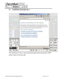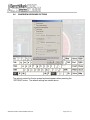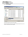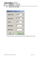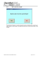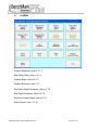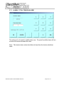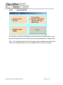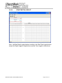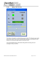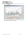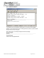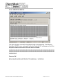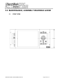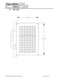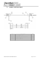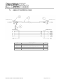
1
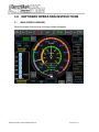
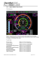
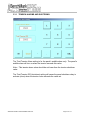
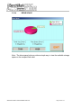
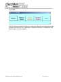
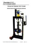
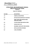
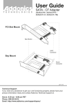
OPERATIONS AND MAINTENANCE MANUAL
WINCH OPERATORS PANEL
AMS3A344
Hoistman’s Display Program Rev: V5.01
Acquisition Program Rev: 2003.10
AMS3A344 PANEL TOUCHSCREEN AUG 2014
Page 1 of 174
TABLE OF CONTENTS
SECTION
1.0
DESCRIPTION
INTRODUCTION
1.1
1.2
1.3
1.4
1.5
1.6
1.7
GENERAL DESCRIPTION
TECHNICAL SPECIFICATIONS
HARDWARE FEATURES
USER INTERFACE FEATURES
OBTAINING TECHNICAL ASSISTANCE
BIOS INSTRUCTION
DUAL BOOT PROCEDURE
2.0
WELLSITE OPERATING SUMMARY
3.0
SOFTWARE OPERATING INSTRUCTIONS
3.1
3.2
3.3
3.4
3.5
3.6
3.7
3.8
3.9
3.10
3.11
INTRODUCTION
TOUCH SCREEN
DEPTH
GAUGES
TENSION
STRETCH
ALARMS
SYSTEM SETUP
LOG VIEW
HELP
RESIZE - EXIT
4.0
INTERNAL PC DATA FILES AND SOFTWARE UPDATE PROCEDURES
5.0
MAINTENANCE, ASSEMBLY DRAWINGS AND BOM
6.0
SCHEMATICS, WIRING DIAGRAMS AND WIRELISTS
7.0
CABLE DRAWINGS
AMS3A344 PANEL TOUCHSCREEN AUG 2014
Page 2 of 174
1.0 INTRODUCTION
1.1
GENERAL DESCRIPTION
AMS3A344 PANEL TOUCHSCREEN AUG 2014
Page 3 of 174
1.1
GENERAL DESCRIPTION continued
This panel is used to acquire and display depth and tension data from a wireline
logging winch unit. The panel provides the operator a means to set and make
adjustments to the data as necessary. Depth is displayed from data provided from
an encoder mounted on a measuring device. The tension data is provided by a load
pin and is also passed through to the acquisition system. The panel will operate with
the BenchMark Dual Wheel Measuring Devices for slick line, braided line, and cased
hole e-line services.
The system consists of two main components, the real time acquisition board and
the PC. The acquisition board provides power to and processes the signals from the
encoders, load pin, and magnetic mark detector. This board operates independent
from the PC and is instantly on when power is applied. It also is connected to
displays for depth and tension. This allows depth and tension to be displayed
immediately on power up and always be displayed regardless of the PC status.
The PC uses an Intel based high speed processor running MS Windows XP
embedded. The PC includes a color touch screen for operator input and command
entry. The PC is Ethernet ready for connection to the internet for remote display and
control.
AMS3A344 PANEL TOUCHSCREEN AUG 2014
Page 4 of 174
1.2
TECHNICAL SPECIFICATIONS
WEIGHT:
PANEL ONLY:
10 LBS
4.55 KG
POWER REQUIREMENTS:
INPUT VOLTAGE:
12 – 24VDC
INPUT CURRENT:
4 AMPS STARTUP SURGE
3 AMPS NORMAL OPERATION
AMS3A344 PANEL TOUCHSCREEN AUG 2014
Page 5 of 174
1.2
TECHNICAL SPECIFICATIONS continued
OPERATING TEMPERATURE
Min Max
14
149 degrees F
-10
65 degrees C
STORAGE TEMPERATURE
Min Max
-22
158 degrees F
-30
70 degrees C
AMS3A344 PANEL TOUCHSCREEN AUG 2014
Page 6 of 174
1.3
HARDWARE FEATURES
12 - 24 VDC Power Input
110/220 VAC 50/60 HZ
Internal PC board
Intel based personal computer board
4 gb solid state media device
Embedded windows XP or Windows 7 operating system
Five USB ports (Two inside, two in front, and one on the back)
1 RS232 port
RJ 45 Ethernet port
USB Mouse / Keyboard included
Color Display
TFT LCD
Backlit
400 NITS Sunlight readable
Touch Screen Interface (replaces current key pad)
5 wire resistive
USB interface
Real Time Acquisition board
Kerr Measurement Systems proprietary design
8051 Microprocessor based
Provides power to encoders, load cell
Processes encoder quadrature, load cell
Runs independent of PC board
Connected to digital displays for real time display of depth and
tension
Overtension Relay Contact Closure output
Analog output interface
Encoder quadrature output
0 – 10vdc tension output
4-20ma tension output
Dual Pressure signal inputs
A second 4gb solid state media device is provided for backup redundancy.
Refer to 3.1.29 for information.
AMS3A344 PANEL TOUCHSCREEN AUG 2014
Page 7 of 174
1.4
USER INTERFACE FEATURES
Total Tension numeric graphic
Incremental or Differential tension meter graphic
Meter reset button graphic (touch screen control)
Over_tension Warnings and Shutdown settings for both Differential and
Total Tension readings (touch screen activated)
Tension Calibration Setup Window (touch screen control)
Encoder Resolution Settings (PPR value set by touch screen control)
Approaching Surface
Max Depth
Set Down
AMS3A344 PANEL TOUCHSCREEN AUG 2014
Page 8 of 174
1.5
OBTAINING TECHNICAL ASSISTANCE
Call BenchMark Wireline Products Inc. at +1 281 346 4300
Or contact by email [email protected]
Or fax in request at +1 281 346 4301
Information is also available on website www.benchmarkwireline.com
Parts can be ordered by email, phone, or fax
Equipment can be returned for repair and maintenance. Please notify us by
Phone, email, or fax before sending any equipment.
To return equipment to BenchMark, ship it to:
BenchMark Wireline Products
36220 FM 1093
Simonton, Texas 77476
U.S.A.
AMS3A344 PANEL TOUCHSCREEN AUG 2014
Page 9 of 174
1.6
BIOS INSTRUCTIONS
Note – Menu items highlighted in YELLOW are the custom settings for this panel.
AMS3A344 PANEL TOUCHSCREEN AUG 2014
Page 10 of 174
1.6
BIOS INSTRUCTIONS continued
AMS3A344 PANEL TOUCHSCREEN AUG 2014
Page 11 of 174
1.6
BIOS INSTRUCTIONS continued
AMS3A344 PANEL TOUCHSCREEN AUG 2014
Page 12 of 174
1.6
BIOS INSTRUCTIONS continued
AMS3A344 PANEL TOUCHSCREEN AUG 2014
Page 13 of 174
1.6
BIOS INSTRUCTIONS continued
AMS3A344 PANEL TOUCHSCREEN AUG 2014
Page 14 of 174
1.6
BIOS INSTRUCTIONS continued
AMS3A344 PANEL TOUCHSCREEN AUG 2014
Page 15 of 174
1.6
BIOS INSTRUCTIONS continued
AMS3A344 PANEL TOUCHSCREEN AUG 2014
Page 16 of 174
1.6
BIOS INSTRUCTIONS continued
AMS3A344 PANEL TOUCHSCREEN AUG 2014
Page 17 of 174
1.6
BIOS INSTRUCTIONS continued
AMS3A344 PANEL TOUCHSCREEN AUG 2014
Page 18 of 174
1.6
BIOS INSTRUCTIONS continued
AMS3A344 PANEL TOUCHSCREEN AUG 2014
Page 19 of 174
1.6
BIOS INSTRUCTIONS continued
AMS3A344 PANEL TOUCHSCREEN AUG 2014
Page 20 of 174
1.6
BIOS INSTRUCTIONS continued
AMS3A344 PANEL TOUCHSCREEN AUG 2014
Page 21 of 174
1.6
BIOS INSTRUCTIONS continued
AMS3A344 PANEL TOUCHSCREEN AUG 2014
Page 22 of 174
1.6
BIOS INSTRUCTIONS continued
AMS3A344 PANEL TOUCHSCREEN AUG 2014
Page 23 of 174
1.6
BIOS INSTRUCTIONS continued
AMS3A344 PANEL TOUCHSCREEN AUG 2014
Page 24 of 174
1.6
BIOS INSTRUCTIONS continued
AMS3A344 PANEL TOUCHSCREEN AUG 2014
Page 25 of 174
1.6
BIOS INSTRUCTIONS continued
AMS3A344 PANEL TOUCHSCREEN AUG 2014
Page 26 of 174
1.6
BIOS INSTRUCTIONS continued
AMS3A344 PANEL TOUCHSCREEN AUG 2014
Page 27 of 174
1.6
BIOS INSTRUCTIONS continued
AMS3A344 PANEL TOUCHSCREEN AUG 2014
Page 28 of 174
1.7
DUAL BOOT PROCEDURE
The age of the panel will determine whether it has the dual boot option.
Follow these instructions to set up to boot from the second compact flash card.
-
Connect a keyboard to the panel.
-
Turn power on to the panel.
-
Press the “DEL” key on the keyboard until the BIOS settings appear.
-
Use the DOWN ARROW key to select “Integrated Peripherals” and press
ENTER (Return) on the keyboard
-
Select “OnChip Device IDE” and press ENTER on the keyboard
-
Use the DOWN ARROW key and select “On-Chip Secondary PCI IDE”
-
Use the PAGE DOWN key and change this setting to “DISABLED”
-
Use the UP ARROW key and select “On-Chip Primary PCI IDE”
-
Use the PAGE DOWN key and change this setting to “ENABLED”
-
Press the F10 key on the keyboard and answer YES to save the settings
-
The panel should start to Re-boot from the second boot device
AMS3A344 PANEL TOUCHSCREEN AUG 2014
Page 29 of 174
2.0 WELLSITE OPERATING SUMMARY
2.1.1 Power up panel and verify it is working properly.
2.1.2 Press Zero Depth and verify that panel tension reads 0. Verify tension is
recorded on acquisition system.
2.1.3 Set line size to match cable size installed in head (refer to section 3).
2.1.4 Set Tension Alarm value (refer to section 3).
2.1.5 Set depth adjust value (refer to section 3).
2.1.6 Install cable in measuring head and lay it slack on the ground.
2.1.7 Press Menu – Tension Cal – Tension Zero to zero the tension value.
2.1.8 Press Menu – Tension Cal – Tension Zero and verify that panel tension reads
the proper tension value for the chosen head/load pin. Verify tension is being
properly recorded on acquisition system.
2.1.9 Pull tool to depth 0 position. Press Zero Depth and verify that panel depth
reads 0. Set acquisition system depth to 0 at this time.
Make sure encoder direction is properly set.
AMS3A344 PANEL TOUCHSCREEN AUG 2014
Page 30 of 174
2.2
LOG FILE BIG MESSAGE
This message may occur if the Events Log File is deemed too large.
This can occur if the program is operating for extended periods of time and the file
has not been saved and re-inited.
It is recommended to save and re-init the Events log file after each job to keep a
record of the events of every job and to avoid this message pop-up. Refer to System
Setup - Events Log Section 3.9.7.1
AMS3A344 PANEL TOUCHSCREEN AUG 2014
Page 31 of 174
2.3
LOG ON SCREEN
Every time that the Hoistman program starts the Operator has the option of
appending the new log information to the previous log file, overwriting the previous
log file, or creating a new log file.
AMS3A344 PANEL TOUCHSCREEN AUG 2014
Page 32 of 174
2.4
LOG ON SCREEN WITH ON SCREEN KEYBOARD
The Operator can Log On to the Hoistman program as Local Admin or Local Control.
Logging On as Local Control restricts some the panel parameters that can be
changed.
Logging On as Local Admin enables all parameters changes and requires a
password.
The panel ships with the Password in 'Remember Me' mode. The password can be
changed only by the Local Admin. Refer To Section 3.9.8 for information on
changing the password. Notice that the pop-up keyboard always appears whenever
the Operator is required to type in a text box.
AMS3A344 PANEL TOUCHSCREEN AUG 2014
Page 33 of 174
2.5
ONSCREEN KEYBOARD HELP
The Help Screen for the on-screen keyboard appears when pressing the “HELP”
button located at the lower right.
AMS3A344 PANEL TOUCHSCREEN AUG 2014
Page 34 of 174
2.6
ONSCREEN KEYBOARD OPTIONS
The options screen for the on-screen keyboard appears when pressing the
“OPTIONS” button. The default settings are shown above.
AMS3A344 PANEL TOUCHSCREEN AUG 2014
Page 35 of 174
2.7
LOG ON BROWSER
Use the Browse feature to pop-up the file manager.
Note that the default extension for the log file is .Hlog and the default location of the
log files is C:\Benchmark Hoistman\LogData\.
AMS3A344 PANEL TOUCHSCREEN AUG 2014
Page 36 of 174
2.8
SERIAL PORT SETTINGS
It is recommended to use the following Serial Port Settings as shown above.
AMS3A344 PANEL TOUCHSCREEN AUG 2014
Page 37 of 174
3.0 SOFTWARE OPERATING INSTRUCTIONS
3.1
MAIN SCREEN OVERVIEW
When the system first boots up, the main screen will appear.
AMS3A344 PANEL TOUCHSCREEN AUG 2014
Page 38 of 174
3.1
MAIN SCREEN OVERVIEW continued
After Log In the Main Screen appears. The sub-menu selection buttons are
accessed across the top of the screen. Allow approximately five (5) seconds for the
panel parameters to be transferred from the Acquisition board to the Hoistman
program before invoking the sub-menus.
Depth/Shim - invokes a sub-menu for setting panel depth and shim. Refer to
Section 3.3.4
Gauges - invokes a sub-menu for setting the main screen gauge scales. Refer to
Section 3.4
Tension - invokes a sub-menu for setting the tension factor and performing tension
calibration. Refer to Section 3.5.1
Stretch Corr - allows the enabling or disabling of the tension based stretch
correction. refer to Section 3.6.1
Alarms - invokes a sub-menu for setting the alarm and shutdown parameters. Refer
to Section 3.7
System Setup - Invokes a sub-menu for setting the majority of panel parameters.
Refer to Section 3.8
Log View - Pressing this button will invoke a pop-up screen of the built-in plotting
program. Refer to Section 3.9.1
Help - Invokes a sub-menu for viewing the software version, the panel manual, and
the panel drive usage and capacity. Refer to Section 3.10.1
Resize & Exit - Invokes a sub-menu for minimizing or exiting the program or
shutting down the Operating System. Refer to Section 3.11.1
Other Main Screen Buttons
Zero Depth - Zeroes the panel depth. Invokes the following pop-up dialog which
asks "Are You Sure You Want To Zero Depth?" to avoid accidental zeroing.
AMS3A344 PANEL TOUCHSCREEN AUG 2014
Page 39 of 174
3.1
MAIN SCREEN OVERVIEW continued
Zero Depth Acknowledgement Dialog
Alarm Silence - Silences the panel alarm. Refer to Section 3.7.14
Reset Tension - Resets the differential tension (DTen/Incr) gauge needle.
Start Job - Invokes a sub-menu for opening the LAS and REC log files. Refer to
Section 3.9.11
Stop Job - Closes the LAS and REC log files. Refer to Section 3.9.13
Events Log – Opens the system events Log File. Refer to Section 3.9.7.1
Shutdown Released/Activated - This button is enabled upon a shutdown condition
allowing the operator to press this button to de-activate the panel shutdown relay.
Refer to Section 3.7.15
AMS3A344 PANEL TOUCHSCREEN AUG 2014
Page 40 of 174
3.2.1 MAIN SCREEN MINIMIZED
Main Screen showing minimal boxes – by double tapping the boxes disappear.
This is the view of the Main Screen when the non-essential text boxes have been
made invisible by double-tapping on the individual text Boxes
Note: The essential text boxes and gauges always remain visible on the main
screen.
All hidden text boxes can be restored by navigating to the system setup sub-menu
and pressing the “Show All” button.
AMS3A344 PANEL TOUCHSCREEN AUG 2014
Page 41 of 174
3.2.2
MAIN SCREEN TOUCH POINTS
Call information
Figure ? shows the various 'touch points on the main screen that invoke dialog
boxes for changing the gauge scales and alarm and shutdown values without having
to navigate to the different sub-menus.
Touch Points
Surface Alarm
Incremental.jpg
Differential.jpg
TensionAlarmAndShutdown.jpg
SpeedAlarms
SetDownAlarmAndSDScale.jpg
TensionScale.jpg
SpeedGaugeScale.jpg
DeltaTensionScale.jpg
Depth Gauge.jpg
AMS3A344 PANEL TOUCHSCREEN AUG 2014
(Refer to 3.7.3 for description)
(Refer to 3.8.19.1 for description)
(Refer to 3.8.19.2 for description)
(Refer to 3.3.1 for description)
(Refer to 3.3.2 for description)
(Refer to 3.3.3 for description)
(Refer to 3.4.1 for description)
(Refer to 3.4.4 for description)
(Refer to 3.4.3 for description)
(Refer to 3.4.2 for description)
Page 42 of 174
3.3.1 TENSION ALARMS AND SHUTDOWN
The Total Tension Alarm setting is for the panel’s audible alarm only. The panel’s
audible alarm will turn on when the tension exceeds this value.
Note – This tension alarm value should be set lower than the tension shutdown
value.
The Total Tension S/D (shutdown) setting will cause the panel shutdown relay to
activate (close) when the tension value exceeds the value set.
AMS3A344 PANEL TOUCHSCREEN AUG 2014
Page 43 of 174
3.3.2 SPEED ALARMS
An audible alarm will sound when values are outside the above parameters.
AMS3A344 PANEL TOUCHSCREEN AUG 2014
Page 44 of 174
3.3.3 SET DOWN ALARM AND SD SCALE
Negative DTEN Alarm is analogous to ‘set down weight’ and the panel’s audible
alarm will turn on when the tension decreased rapidly in a negative direction.
The Negative DTEN S/D setting will cause the panel shutdown relay to activate
(close).
This function is similar to a differential tension shutdown except that it only activates
when the value is exceeded. This will occur when tension decreases rapidly in a
negative direction.
When this event occurs the shutdown relay will close.
Default: 750
AMS3A344 PANEL TOUCHSCREEN AUG 2014
Page 45 of 174
3.3.4 DEPTH – SUBMENU
DEPTH SET - Allows changing the panel depth
OFFSET DEPTH – Displays the panel depth previous to the operator performing a
“Depth Set”.
Depth Shim
Adds or subtracts depth continually.
If 1 is entered then 1 foot or 1 meter will be added every 1000 feet or 1000 meters.
If -.2 is entered then .2 feet or .2 meters will be subtracted every 1000 feet or 1000
meters.
Default is 0.0
AMS3A344 PANEL TOUCHSCREEN AUG 2014
Page 46 of 174
3.4
GAUGES - MENU
TTEN - The Total Tension Scale Screen allows the changing of the outer gauge
scale at the center of the screen.
DTEN - Inner Gauge Scale – Incremental/Differential tension provides a high
resolution tension scale. It must be periodically reset as tension increases or
decreases to keep it from “pegging out” when set to Incremental Mode.
DEPH – Allows the changing of the depth scale located at the lower left of the main
screen.
SPEED – Allows the changing of the speed scale located at the lower center of the
main screen.
AMS3A344 PANEL TOUCHSCREEN AUG 2014
Page 47 of 174
3.4.1
GAUGES – TTEN GAUGE SCALE
Sets the outer total tension gauge scale on the Main Screen.
AMS3A344 PANEL TOUCHSCREEN AUG 2014
Page 48 of 174
3.4.2
GAUGES - DEPTH GAUGE
Sets the bottom of the well depth gauge scale on the main screen.
AMS3A344 PANEL TOUCHSCREEN AUG 2014
Page 49 of 174
3.4.3
GAUGES – DELTA / INCREMENTAL TENSION (DTEN)
Sets the inner delta / incremental gauge scale on the main screen.
AMS3A344 PANEL TOUCHSCREEN AUG 2014
Page 50 of 174
3.4.4
GAUGES - SPEED GAUGE
Sets the speed gauge scale on the main screen.
AMS3A344 PANEL TOUCHSCREEN AUG 2014
Page 51 of 174
3.5.1
TENSION – SUB MENU
This submenu provides function or calibrating and testing the load on or load cell.
Tension Calibrate – refer to section 3.5.2
Tension Factor – refer to section 3.5.6
Test LC Shunt – refer to section 3.5.7
Release LC Shunt – refer to section 3.5.8
AMS3A344 PANEL TOUCHSCREEN AUG 2014
Page 52 of 174
3.5.2
TENSION CALIBRATE
AMS3A344 PANEL TOUCHSCREEN AUG 2014
Page 53 of 174
3.5.3 TENSION ZERO
Pressing Tension Zero will null out any tension offset voltage up to 1,000 lbs.
NOTE - Depth value must be zeroed before this menu can be displayed.
NOTE - Tension value must be less than 1,000 lbs before this menu is displayed.
AMS3A344 PANEL TOUCHSCREEN AUG 2014
Page 54 of 174
3.5.4 TENSION CAL – HIGH TENSION
The load pin will automatically shunt when this screen appears. The ‘current
tension’ text box above will display the load pin’s shunt tension value.
AMS3A344 PANEL TOUCHSCREEN AUG 2014
Page 55 of 174
3.5.5 TENSION CAL
Pressing Tension Cal will activate the tension relay inside the panel. The load pin
should then return a calibrated signal that varies depending on the head chosen.
3K HEAD
5K HEAD
MAKO HEAD
SHARK HAD
MEGAMOUTH HEAD
DOLPHIN HEAD
HYD-SL
OTHER
AMS3A344 PANEL TOUCHSCREEN AUG 2014
5,000 LBS
10,000 LBS
10,000 LBS
4,000 LBS
5,000 LBS
5,000 LBS
10,000 LBS
5,000 LBS
Page 56 of 174
3.5.6 TENSION FACTOR
The Set Tension Factor entry screen will appear. The range is 0.5-2.0 degrees.
Default is 1.0.
Explanation: Tension Factor as it relates to Load Cell angle
Load cell angle is used to compensate when a load cell is not hung vertically (i.e.
bottom sheave). Enter the value derived from the formula:
AMS3A344 PANEL TOUCHSCREEN AUG 2014
Page 57 of 174
3.5.7
TEST LOAD CELL SHUNT
This allows the Operator to test the loadcell circuits and cabling if the loadcell and
cable support a shunt resistor. Be aware that this does not test the accuracy of the
loadcell.
AMS3A344 PANEL TOUCHSCREEN AUG 2014
Page 58 of 174
3.5.8
RELEASE LOAD CELL SHUNT
Allows the Operator to release the loadcell shunt after testing.
AMS3A344 PANEL TOUCHSCREEN AUG 2014
Page 59 of 174
3.6.1 STRETCH CORRECTION – ENABLE STRETCH
The Default selection is: Enabled.
Enabling this allows stretch correction to automatically be applied to the depth. The
correction is calculated using line size Parameters.
Stretch is calculated by stretch due to cable weight + stretch due to weight at end of
cable.
Stretch due to cable weight = stretch coefficient * depth * cable weight / 2.
Stretch due to weight at end of cable = stretch coefficient * depth * (tension – cable
weight).
When tension is less than cable weight, tension measured is due to cable weight
alone.
AMS3A344 PANEL TOUCHSCREEN AUG 2014
Page 60 of 174
3.6.2 STRETCH CORRECTION – DISABLE STRETCH
In Stretch Correction disabled mode the panel depth reflects the encoder depth and
the effects of tension impacted on the cable are ignored.
AMS3A344 PANEL TOUCHSCREEN AUG 2014
Page 61 of 174
3.7
ALARMS
Tension Shutdown: refer to 3.7.2
Max Depth Alarm: refer to 3.7.4
Surface Alarm: refer to 3.7.3
Surface Shutdown: refer 3.7.7
Set Down Weight Shutdown: refer to 3.7.6
Max Depth Shutdown: refer to 3.7.8
Set Down Weight Alarm: refer to 3.7.5
Alarm Events: refer t 3.7.16
AMS3A344 PANEL TOUCHSCREEN AUG 2014
Page 62 of 174
3.7
ALARMS continued
Test Shutdown: refer to 3.7.9
Release Shutdown: refer to 3.7.10
Test Alarm: refer to 3.7.12
Alarm Off: refer to 3.7.13
Alarm Volume: refers to 3.7.11
NOTE - All shutdowns refer to the relay contact closure. It is the operator’s
responsibility to connect the relay contacts to the actual reel shutdown mechanism.
Future Feature
Disable Tension Shutdown: refer to 3.7.14
Enable Tension Shutdown: refer to 3.7.15
AMS3A344 PANEL TOUCHSCREEN AUG 2014
Page 63 of 174
3.7.1 ALARM - TOTAL TENSION ALARM
This setting is for the panel’s audible alarm only. The panel’s audible alarm will turn
on when the tension exceeds this value.
Note – This tension alarm value should be set lower than the tension shutdown
value.
AMS3A344 PANEL TOUCHSCREEN AUG 2014
Page 64 of 174
3.7.2 ALARM - TENSION SHUTDOWN
The Set Tension S/D entry screen will appear. The range is 0.1 to 19999
When this value is reached, alarm sounds, tension display flashes value, and
tension contact closure switch is closed. This can be used to provide a signal to
automatically stop the winch.
Each wireline size will have a corresponding Tension Alarm setting. Only the setting
for the cable size selected can be adjusted.
Default is 2000 lbs
NOTE – Tension shutdown is also accessible from the Setup Menu.
AMS3A344 PANEL TOUCHSCREEN AUG 2014
Page 65 of 174
3.7.3 ALARM - SURFACE ALARM
The Set Surface Alarm entry screen will appear. The range is 0-304 Mt or 0 to 999 ft.
When this depth value is reached, the alarm will sound warning the operator that you
are approaching the surface.
Default: is 100 feet.
If surface shutdown is enabled, then relay will close.
Refer to section – 3.7.7
AMS3A344 PANEL TOUCHSCREEN AUG 2014
Page 66 of 174
3.7.4 ALARM - MAX DEPTH ALARM
The Set Max Depth Alarm entry screen will appear. The range is from the surface
alarm setting to 30,000 feet.
Allows you to enter in the maximum depth desired. If the tool goes below that depth
then an alarm will sound. If max depth shutdown is enabled, then the relay will close
(refer to section 3.7.8).
Default: 30,000 ft.
AMS3A344 PANEL TOUCHSCREEN AUG 2014
Page 67 of 174
3.7.5 ALARM - SET DOWN WEIGHT (Negative DTEN Alarm)
Negative DTEN Alarm is analogous to ‘set down weight’ and the panel’s audible
alarm will turn on when the tension decreased rapidly in a negative direction.
AMS3A344 PANEL TOUCHSCREEN AUG 2014
Page 68 of 174
3.7.6 ALARM - DELTA TENSION SHUTDOWN (Negative DTEN Shutdown)
The Negative DTEN S/D entry screen will appear. The range is 0.1 to 5000
This function is similar to a differential tension shutdown except that it only activates
when the value is exceeded. This will occur when tension decreases rapidly in a
negative direction.
When this event occurs the shutdown relay will close.
Default: 750
AMS3A344 PANEL TOUCHSCREEN AUG 2014
Page 69 of 174
3.7.7 ALARM - SURFACE SHUTDOWN
When pressing this button and the surface shutdown is disabled, the ‘Enable
Surface Shutdown’ message is shown in the dialog screen. Refer to Surface
Shutdown Alarm 3.7.3.
If enabled, the relay will close and the winch will stop when the surface alarm depth
value is reached.
Default: Disabled
When the surface shutdown is enabled, the ‘disable surface shutdown?’ message is
shown in the dialog screen.
AMS3A344 PANEL TOUCHSCREEN AUG 2014
Page 70 of 174
3.7.8
ALARM - MAX DEPTH SHUTDOWN
When pressing this button and the max depth shutdown is disabled, the ‘enable max
depth shutdown is disabled, the ‘enable max depth shutdown?’ message is shown in
the dialog screen.
If enabled, the relay will close and the winch will stop when the maximum depth
value is reached. The maximum depth value is set on the max depth alarm screen
(refer to section 3.7.8).
Default: disabled
When the max depth shutdown is enabled, the ‘disable max depth shutdown?’
message is shown in the dialog screen.
AMS3A344 PANEL TOUCHSCREEN AUG 2014
Page 71 of 174
3.7.9
ALARM - TEST SHUTDOWN
When this button is pressed, the contact closure pins are shorted. This can be used
to test the winch shutdown mechanism or any other mechanism that uses these
contacts.
AMS3A344 PANEL TOUCHSCREEN AUG 2014
Page 72 of 174
3.7.10
ALARM - RELEASE SHUTDOWN
When this button is pressed, the contact closure pins (A and B) on J8 are open.
AMS3A344 PANEL TOUCHSCREEN AUG 2014
Page 73 of 174
3.7.11
ALARM VOLUME
For safety reasons the audible alarm is always set to maximum volume when the
panel is power-cycled, regardless of the setting prior to the power-cycle.
AMS3A344 PANEL TOUCHSCREEN AUG 2014
Page 74 of 174
3.7.12
ALARM - TEST ALARM
The panel has an internal audible alarm which can be tested through the dialogue
screen. To adjust the volume level refer to 3.1.8.10
AMS3A344 PANEL TOUCHSCREEN AUG 2014
Page 75 of 174
3.7.13
ALARM OFF
NOTE – There is no dialog screen associated with this function. Refer to the Main
Screen 3.1.
AMS3A344 PANEL TOUCHSCREEN AUG 2014
Page 76 of 174
3.7.14
ALARM - DISABLE TENSION SHUTDOWN
Under some circumstances the Operator may deem it necessary to disable the
tension shutdown. The shutdown relay contacts will not close if disabled.
WARNING: Disabling Tension Shutdown is potentially dangerous. Use with care.
Note – this feature is not currently available.
AMS3A344 PANEL TOUCHSCREEN AUG 2014
Page 77 of 174
3.7.15
ALARM - ENABLE TENSION SHUTDOWN
This setting is the default. The panel relay contacts will close if a shutdown condition
exists. It is the responsibility of the customer to connect the panel relay contacts to
the system shutdown mechanism.
AMS3A344 PANEL TOUCHSCREEN AUG 2014
Page 78 of 174
3.7.16
ALARM EVENTS
The Alarm Events sub-menu allows the operator to design a more sophisticated set
of alarm conditions.
The 'Surface Alarm/Bottom Catch/Spooling Down/Spooling Up' operation controls
actually are all speed controls, so the value typed in the column 'Speed/Tension' are
speed range. For the 'Tension Control', it's tension range.
The tension alarm of operation control doesn't affect the regular tension alarms (for
example tension shut down and tension alarm), its information is displayed on the
'Alarm' buttons of the main screen and setup menu.
This information is shown, for example, when the depth goes inside depth range
(6000 to 7000), the operation control information is displayed on the 'Alarm' button of
the main screen and on the 'Alarm Events' button of the setup menu screen.
AMS3A344 PANEL TOUCHSCREEN AUG 2014
Page 79 of 174
3.7.16
ALARM EVENTS continued
If there is a '+' at the end of the text of the two buttons, that means there is more
than one operation control in this depth range. In this example while the direction
goes down and the depth goes inside the depth range 6000 to 7000, there are three
operation controls: row 3/TTen Control, row 4/DTen Control and row 7/Down In
CaseHole.
Also if inside the operation control's depth range and the system tension changes
outside of the tension range, the system will give an audible alarm.
When the depth goes inside a speed control's depth range, the system will change
the speed ribbon of the speed gauge on the main screen according to the speed
setting value. For example, when the depth goes inside 16305.8 to 16240.2, the
speed ribbon is set to 131.2 to 164.0 automatically.
BEEP OPERATION CHECK BOX:
When the depth goes inside one operation control's depth operating range, the
check box is used for setting if the system gives an audible alarm or just display the
operation information on the main screen 'alarm' button.
At the left split window of the 'Operation Control Window', you could check the
'Surface Alarm/Bottom Catch/Spooling Down/Spooling Up' or click the 'Speed
Control/Tension Control' to insert one operation control to the right split window.
Uncheck the check box to remove the operation control from the right split window.
Also you could select one operation control and click the button 'Delete Select
Control' to delete one operation control.
Inside the operation control edit table, a cell can be edited by double-clicking on it. If
there is no response that means it has a default value that the operator cannot edit.
For example 'Well Structure' in the depth column of ' Bottom Catch/Spooling
Down/Spooling Up', the system will generate the depth range according to the well
bottom depth.
AMS3A344 PANEL TOUCHSCREEN AUG 2014
Page 80 of 174
3.8
SYS SETUP MENU
Following are the functional descriptions of each of the buttons:
AMS3A344 PANEL TOUCHSCREEN AUG 2014
Page 81 of 174
3.8.1 SYS SETUP - HEAD TYPE
If the “Other” head is chosen, the operator has the option of choosing a variety of
wheel sizes listed in 3.8.2
If the “HYD_SL” head is chosen, the operator has the option of choosing from two
different wheel sizes listed in 3.8.3.1
For all other head selections, the wheel sizes are automatically determined and
cannot be changed. The load pin types are also automatically determined by the
head selection.
Note – it is recommended to check the Line Size AFTER changing Head Types.
AMS3A344 PANEL TOUCHSCREEN AUG 2014
Page 82 of 174
3.8.2 SYS SETUP - WHEEL SIZE (OTHER)
This setting allows you to change the size of the depth measuring wheel that is used
to measure depth. To use a different measuring head from the Benchmark head,
this setting will need to be changed to match the wheel size of the new head.
AMS3A344 PANEL TOUCHSCREEN AUG 2014
Page 83 of 174
3.8.3.1
HYD_SL HEAD PARAMATERS
WHEEL SIZE – note that there are two available wheel sizes. One is Imperial and
one is Metric. If the wheel size is not one of these options, change the Encoder In
PPR (pulses per revolution) to adjust for the correct size.
AMS3A344 PANEL TOUCHSCREEN AUG 2014
Page 84 of 174
3.8.3.2
LBS per PSI
Use this setting to adjust the tension reading.
AMS3A344 PANEL TOUCHSCREEN AUG 2014
Page 85 of 174
3.8.4
ENG/MET UNITS
This menu allows you to select the display units for either depth or tension. Default is
feet and lbs.
AMS3A344 PANEL TOUCHSCREEN AUG 2014
Page 86 of 174
3.8.5.1
LINE SIZE - 20” MAKO / ORCA / THRESHER HEAD
Select the line size by pressing the corresponding button. Default is .108
Note – select the head BEFORE selecting the line size.
AMS3A344 PANEL TOUCHSCREEN AUG 2014
Page 87 of 174
3.8.5.2
LINE SIZE – SHARK HEAD
Select the line size by pressing the corresponding button. Default is .108
AMS3A344 PANEL TOUCHSCREEN AUG 2014
Page 88 of 174
3.8.5.3
LINE SIZE – MEGAMOUTH AND DOLPHIN HEAD
AMS3A344 PANEL TOUCHSCREEN AUG 2014
Page 89 of 174
3.8.5.4
LINE SIZE - 5K (Braided Line) HEAD
Select the line size by pressing the corresponding button. Default is 5/16
AMS3A344 PANEL TOUCHSCREEN AUG 2014
Page 90 of 174
3.8.5.5
LINE SIZE – HYD SL
AMS3A344 PANEL TOUCHSCREEN AUG 2014
Page 91 of 174
3.8.6.1
CABLE MANAGEMENT
Cable management is a new feature to this version of the Hoistman program. This
feature enables the Operator to document cable usage as an aid in determining
cable wear.
AMS3A344 PANEL TOUCHSCREEN AUG 2014
Page 92 of 174
3.8.6.2
LINE SELECTION
A table is created for every available line size. In each table the Cable Number can
be changed by selecting the line and pressing the 'Rename Line NO. button'.
A new line can be added by pressing the 'New Line' button and an existing line can
be deleted by selecting a line and pressing the 'Delete Line' button.
To change the parameters select the line in the table and then press the 'OK' button
to close the table and return to the Cable Management sub-screen.
Note - When Head Type 'Other' is chosen all line sizes are shown in the Line
Selection Table.
AMS3A344 PANEL TOUCHSCREEN AUG 2014
Page 93 of 174
3.8.6.3
MILEAGE
Note – this value is per thousand feet.
AMS3A344 PANEL TOUCHSCREEN AUG 2014
Page 94 of 174
3.8.6.4
STRETCH COEFFICIENT
Note – this value is feet per thousand feet per thousand pounds. (FT/KFT/KLBS)
AMS3A344 PANEL TOUCHSCREEN AUG 2014
Page 95 of 174
3.8.6.5
LINE WEIGHT
Note – this value is pounds per thousand feet. (LBS/KFT)
AMS3A344 PANEL TOUCHSCREEN AUG 2014
Page 96 of 174
3.8.6.6
WORKING LOAD
AMS3A344 PANEL TOUCHSCREEN AUG 2014
Page 97 of 174
3.8.6.7
MAX TENSION
AMS3A344 PANEL TOUCHSCREEN AUG 2014
Page 98 of 174
3.8.7 ENCODER DIRECTION
This screen allows you to change the direction of the encoder. If the depth is
changing in the opposite direction to which the line is moving, this option can be
used to correct it. On a dual wheel measuring device with two encoders, the
encoder on one of the wheels will turn in the opposite direction from the other. If you
change encoders, this feature can be used to change the encoder direction.
AMS3A344 PANEL TOUCHSCREEN AUG 2014
Page 99 of 174
3.8.8 ENCODER STATUS
The panel provides for two redundant encoder input circuits, but only one encoder
can be Enabled at a time. Note that the encoder direction (refer to Section 3.8.7)
may need to be reversed when changing the enabled encoder.
AMS3A344 PANEL TOUCHSCREEN AUG 2014
Page 100 of 174
3.8.9.1
PULSES OUT ENABLE
NOTE - This menu determines whether encoder pulses are sent to the logging
system when the operator performs a “set depth” or a “zero depth” action.
This message appears on this dialog screen when the ‘pulses out on set depth’
option is disabled.
AMS3A344 PANEL TOUCHSCREEN AUG 2014
Page 101 of 174
3.8.9.2
PULSES OUT DISABLE
This message appears on this dialog screen when the ‘pulsed out on set depth’
option is enabled.
AMS3A344 PANEL TOUCHSCREEN AUG 2014
Page 102 of 174
3.8.10
ENCODER IN PPR
The range is 1-2000
The screen allows you to set the encoder pulses per revolution setting. This number
should be printed on the encoder label.
Note - The encoder output pulses per foot/meter are not set by this screen, only the
encoder input. The encoder output pulses per foot/meter are calculated from
encoder PPR and Wheel Size.
Default is 1200 PPR
AMS3A344 PANEL TOUCHSCREEN AUG 2014
Page 103 of 174
3.8.11
ENCODER OUTPUT PPF
This determines the encoder pulses out per foot and is independent of the encoder
in pulses per revolution.
AMS3A344 PANEL TOUCHSCREEN AUG 2014
Page 104 of 174
3.8.12.1
PRESSURE 1
This menu controls pressure 1 values and displays.
Note – this is the label that appears on the main screen above the pressure valve.
Note – the on-screen keyboard will appear when tapping inside the ‘name’ next box.
AMS3A344 PANEL TOUCHSCREEN AUG 2014
Page 105 of 174
3.8.12.2
PRESSURE FULLSCALE
The menu adjusts the settings for Fullscale PSI and the default setting is 10000
PSI - This value corresponds with the 20ma point of a 4-20ma current loop.
Note – the on-screen keyboard will appear when tapping inside the PSI text box.
AMS3A344 PANEL TOUCHSCREEN AUG 2014
Page 106 of 174
3.8.12.3
ENABLE / DISABLE PRESSURE 1
When Pressure 1 and/or Pressure 2 are enabled, the main screen will display these
values. Once disabled these values will be removed from the main screen
AMS3A344 PANEL TOUCHSCREEN AUG 2014
Page 107 of 174
3.8.12.4
ZERO
Zero - Pressing this button establishes the zero pressure point. This corresponds
with 4ma point on a 4-20ma current loop.
Note – There is no image associated with this action.
Note – The pressure will not be zeroed if the current is more than +/- 20% of 4ma.
AMS3A344 PANEL TOUCHSCREEN AUG 2014
Page 108 of 174
3.8.13
PRESSURE 2
The settings menus for Pressure 2 are identical to Pressure 1. (See sections
3.8.12.1 through 3.8.12.4 for more information.)
AMS3A344 PANEL TOUCHSCREEN AUG 2014
Page 109 of 174
3.8.14
RESTORE DEFAULTS
When this button is pressed, all the settings will be restored to their default values.
This functions as a software reset. Depth will be zeroed.
Note - It is recommended to perform a restore defaults after a software update.
AMS3A344 PANEL TOUCHSCREEN AUG 2014
Page 110 of 174
3.8.15
SUMMARY
The Summary Menu is a quick reference to what parameters are set. This is a static
display. All of the defaults are shown.
AMS3A344 PANEL TOUCHSCREEN AUG 2014
Page 111 of 174
3.8.16
LOG FILE SETUP
The operator can choose to add data to the log file every 100 milliseconds or every
second. Be aware that the 100 millisecond option potentially results in large log files.
Note - The 'Update Only When Tension Changes option' enabled means that the log
file will not be updated when the tool is stopped and tension does not change.
AMS3A344 PANEL TOUCHSCREEN AUG 2014
Page 112 of 174
3.8.17 START TIME LOGPLOT
The LogPlot is a third-party plotting program that can invoked from this menu. A
time-stamp named file is automatically created in c:\logplotfiles\ subdirectory.
AMS3A344 PANEL TOUCHSCREEN AUG 2014
Page 113 of 174
3.8.18
START DEPTH LOGPLOT
Note - the Start Depth Logplot button is similar to the Start Time Logplot button
except the Depth Logplot is depth driven and the Time Logplot is time driven.
AMS3A344 PANEL TOUCHSCREEN AUG 2014
Page 114 of 174
3.8.19.1
INCREMENTAL
This feature affects how the main screen differential / incremental gauge needle
movement behaves.
This message appears in the dialog when the gauge is set to differential mode.
AMS3A344 PANEL TOUCHSCREEN AUG 2014
Page 115 of 174
3.8.19.2
DIFFERENTIAL
This feature affects how the main screen differential / incremental gauge needle
movement behaves.
This message appears in the dialog when the gauge is set to incremental mode.
AMS3A344 PANEL TOUCHSCREEN AUG 2014
Page 116 of 174
3.8.20
SERIAL PORT STATUS
This dialog is intended for troubleshooting purposes only. The Operator can monitor
this screen to see if there are any communication problems on the Serial Port link
between the hoistman program and the Acquisition board.
The recommended setting is the fastest setting without receiving ‘time-out’
messages in the port text box.
AMS3A344 PANEL TOUCHSCREEN AUG 2014
Page 117 of 174
3.9.1
LOG VIEW
This is the hoistman program built-in plotting utility. The scales are automatically
determined (auto-scaling). Below are the options:
AMS3A344 PANEL TOUCHSCREEN AUG 2014
Page 118 of 174
3.9.2 LOG - PRINT
The panel must be connected to a USB printer and the printer drivers must be
pre-installed for this option to print.
Note – The image above appears if no printer is installed.
AMS3A344 PANEL TOUCHSCREEN AUG 2014
Page 119 of 174
3.9.3 LOG - PRINT PREVIEW
This allows the Operator the option of viewing the printed page before actually
printing.
AMS3A344 PANEL TOUCHSCREEN AUG 2014
Page 120 of 174
3.9.4 LOG - EXPORT TO JPG
The plot can be exported to a .jpg file format.
AMS3A344 PANEL TOUCHSCREEN AUG 2014
Page 121 of 174
3.9.5 LOG - EXPORT TO PDF
The plot can be exported to a .pdf file format.
AMS3A344 PANEL TOUCHSCREEN AUG 2014
Page 122 of 174
3.9.6 LOG - LOGVIEW CURVE SELECT
All available inputs are listed in the table on the right and the Operator can choose
which inputs to add to the plot by moving the selected input to the table on the left.
Record Up:
The Operator can instruct the plotting utility to only plot when the depth is moving
uphole.
Record Down:
The Operator can instruct the plotting utility to only plot when the depth is moving
downhole.
AMS3A344 PANEL TOUCHSCREEN AUG 2014
Page 123 of 174
3.9.7 LOG - RECORD TIME
The Operator can instruct the plotting utility to plot all of the time (time-based).
AMS3A344 PANEL TOUCHSCREEN AUG 2014
Page 124 of 174
3.9.7.1
SYSTEM EVENTS LOG
The System Events Log can be saved to disk by pressing the “save-as” button this
file contains event information that can be used for troubleshooting purposes.
The pressing “Init Log” button will delete the existing event log and create a new
event log.
AMS3A344 PANEL TOUCHSCREEN AUG 2014
Page 125 of 174
3.9.8
NEW PASSWORD
This Password can only be changed by logging in to the program as an
administrator.
Note – If the password is lost, the hoistman program must be reinstalled to reset the
password.
AMS3A344 PANEL TOUCHSCREEN AUG 2014
Page 126 of 174
3.9.9
SYSTEM WORKING STATUS
This dialog allows the Operator to change the password if he is already an
Administrator.
Local Admin – in this mode the operator is allowed to change all parameters.
Local Control – in this mode the operator is restricted in their ability to change some
parameters.
AMS3A344 PANEL TOUCHSCREEN AUG 2014
Page 127 of 174
3.9.10
SHOW ALL
Pressing this button restores all invisible text boxes to visible mode on the main
screen.
AMS3A344 PANEL TOUCHSCREEN AUG 2014
Page 128 of 174
3.9.11
START JOB
An on-screen keyboard is provided automatically for data entry.
Upon closing of the dialog screen a LAS file is created using the time stamp as the
name of the file. This file name is displayed on the main screen. If job is not started
the main screen will show no file – must start job!
Note: No LAS file is created until the operator chooses ‘start job.’
The LAS files are stored in the c:\las files\subdirectory
Rec File – upon the closing of this dialog screen a Rec File is also created. A Rec
File is a text file that is simplier than the LAS file.
AMS3A344 PANEL TOUCHSCREEN AUG 2014
Page 129 of 174
3.9.12
START JOB BROWSE
File names are automatically generated but the operator can choose to rename the
file by tapping in the ‘file to record’ text box.
AMS3A344 PANEL TOUCHSCREEN AUG 2014
Page 130 of 174
3.9.13
END JOB
If the response is “Yes” then the LAS file and the Rec Files are closed. The button
“Start Job” is enabled once again and all buttons in the Setup Menu are re-enabled.
AMS3A344 PANEL TOUCHSCREEN AUG 2014
Page 131 of 174
3.10.1
HELP MENU
The HELP button will display the four options displayed above.
AMS3A344 PANEL TOUCHSCREEN AUG 2014
Page 132 of 174
3.10.2
HELP MANUAL
MANUAL button invokes the Adobe Acrobat Reader with c:\manual.pdf. It will bring
up this manual in pdf format.
AMS3A344 PANEL TOUCHSCREEN AUG 2014
Page 133 of 174
3.10.3
ABOUT SCREEN
The ABOUT button displays the software revisions.
There are two programs that can be updated, the HOISTMAN program which is run
by the PC and the ACQUISITION program that is run by the real time board.
AMS3A344 PANEL TOUCHSCREEN AUG 2014
Page 134 of 174
3.10.4
DRIVE SPACE
Note - The drive space button provides a simple way to view the available storage
space on the compact flash card.
AMS3A344 PANEL TOUCHSCREEN AUG 2014
Page 135 of 174
3.11.1 EXIT
The Exit sub-menu allows the Operator to choose to Minimize the Hoistman program
(program still running), Exit to Windows, or Shutdown Windows. The Maximize and
Resize option is not yet available.
AMS3A344 PANEL TOUCHSCREEN AUG 2014
Page 136 of 174
3.11.2
REDUNDANT BACKUP SOLID STATE DEVICE
The Model 344 panel provides a backup solid state device that can be enabled in
the case that the default drive operating system becomes corrupted and unbootable.
WARNING – only one device can be enabled at a time or damage will result to both
operating systems.
To change the bootable device from the panel default (IDE channel 1 master) to the
backup (IDE channel 0 master) cycle power on the panel and press the ‘DEL’ key
(on the USB keyboard plugged into the front panel) and wait to enter the CMOS
setup utility. Now proceed to the ‘INTEGRATED PERIPHERALS’ menu and then
proceed to the ‘ON-CHIP IDE DEVICE’ menu and disable the ‘ON-CHIP
SECONDARY PCI IDE’ and then enable the ‘ON-CHIP PRIMARY PCI IDE’. Press
the ‘ESC’ key twice and then navigate to ‘SAVE & EXIT SETUP’ and press ‘Y’ for
Yes-save and quit.
AMS3A344 PANEL TOUCHSCREEN AUG 2014
Page 137 of 174
4.0 INTERNAL PC DATA FILES AND SOFTWARE
UPDATE PROCEDURES
NOTE: A USB KEYBOARD IS RECOMMENDED FOR SOFTWARE
INSTALLATION.
The Hoistman Program is released as a .MSI installation file. The Operator doubleclicks on the .msi file and the installation will proceed. It is recommended to use the
default location (C:\Benchmark Hoistman\) for the installation.
4.1
LAS AND HLOG, DATA FILES AND REC FILES
Files located in C:\benchmark hoistman\logdata
NOTE: A USB KEYBOARD IS RECOMMENDED FOR SOFTWARE
INSTALLATION.
The Hoistman Program is released as a .MSI installation file. The Operator doubleclicks on the .msi file and the installation will proceed. It is recommended to use the
default location (C:\Benchmark Hoistman\) for the installation.
AMS3A344 PANEL TOUCHSCREEN AUG 2014
Page 138 of 174
4.2.1 UPDATE 2K PART 1
The Acquisition program is installed using the Software Install Utility which can be
accessed by double-clicking the Desktop icon "Software Install". The utility screen
contains the instructions for re-programming the Acquisition board. Upon pressing
the 'Start' button the utility will automatically open a Hyperterminal session and then
send a re-boot command to the Acquisition board.
AMS3A344 PANEL TOUCHSCREEN AUG 2014
Page 139 of 174
4.2.2 UPDATE 2K PART 2
The Operator must be prepared to quickly type a 'p' as soon as the message
appears on the Hyperterminal screen. If the opportunity to press 'p' passes, repeat
the procedure from the start again.
After receiving the 'p' the utility will respond with this message:
Erasing Program
Memory.............................................................................................................
...............................................................................................................
Program Erased.
send hex file using hyperterminal
AMS3A344 PANEL TOUCHSCREEN AUG 2014
Page 140 of 174
4.2.3 UPDATE 2K PART 3
After receiving the above message from the utility proceed to the Hyperterminal
'Transfer' pull-down menu and choose 'Send Text File' and then pull-down 'Files Of
Type' and choose 'All Files(*.*)' and then choose the latest revision hex file
(hint: s344_2k_XX.hex).
AMS3A344 PANEL TOUCHSCREEN AUG 2014
Page 141 of 174
4.2.4 UPDATE 2K PART 4
This figure shows a successful Acquisition board re-programming. The following
illustrates 'GOOD' sector writes and finally the 'Reveived OK' message and then the
Acquisition board re-boots with the new version software.
GGGGGGGGGGGGGGGGGGGGGGGGGGGGGGGGGGGGGGGGGGGGGGGG
GGGGGGGGGGGGGGGGGGGGGGGGGGGGGGGGGGGGGGGGGGGGGGGG
GGGGGGGG
Received OK.
BENCHMARK WIRELINE PRODUCTS AMS3A344 - VERSION 1
AMS3A344 PANEL TOUCHSCREEN AUG 2014
Page 142 of 174
5.0 MAINTENANCE, ASSEMBLY DRAWINGS & BOM
5.1
FRONT VIEW
AMS3A344 PANEL TOUCHSCREEN AUG 2014
Page 143 of 174
5.2
SIDE VIEW
AMS3A344 PANEL TOUCHSCREEN AUG 2014
Page 144 of 174
5.3
REPLACING ENTERNAL FLASH CARD
5.3.1 Locate the PC processor board mounted to the front panel. Remove zip tie
from the top left corner. The card is on the back side of this board.
5.3.2 Using a pen or small screwdriver press the reject tab. The card will then pop
out of the holder.
AMS3A344 PANEL TOUCHSCREEN AUG 2014
Page 145 of 174
5.3
REPLACING ENTERNAL FLASH CARD continued
5.3.3 The card can now be removed using small needle nose pliers.
5.3.4
To re-install a card place it in the slot, then press it in until you feel it
latch into place. A small screwdriver or pen may be required to fully
insert.
AMS3A344 PANEL TOUCHSCREEN AUG 2014
Page 146 of 174
5.4
BOM – BILL OF MATERIALS
LINE
1
2
3
P/N
AM2KP134
40100
AMS5P221
5
AMS5P015
6
8
9
10
11
AMS4A373
AMS4A577
AMS4P577
AMS4P513
AMS4A549
13
AMS4P128
14
15
17
19
22
23
24
ACMU1P02
AMS4A322
AMS4A644
ALS3A034
AMS4P307
ALS1P032
AMS4P252
26
AMS4M136
27
28
29
30
31
32
AMS4M095
AMS4M343
AMS4M092
AMS4M034
AMS4M037
AMS4M057
33
AMS4M039
34
35
36
37
38
39
AMS4M076
AMS7M002
ALS1P011
AMS4P362
AMS4P363
AMS4A572 A
40
AMS5P076
DESCRIPTION
PC BOARD AMS2K ACQUISITION
LICENSE WINDOWS WIN7 EMBEDDED
MEMORY COMPACT FLASH 8.0GB
COMPUTER SINGLE BOARD 1.6GHZ 2GB RAM INTEL
ATOM PROCESSOR
CABLE ASSY ADVANTECH VIDEO 12.4" LCD DISPLAY
LCD ASSY 12.1 USE AMS4K577 W/TOUCHSCREEN
LCD 12.1 COLOR TFT SHARP BACKLIT 350 NITS
SCREEN TOUCH RESISTIVE 12.1 4W
PCB ASSY CONTROL LG TOUCH PNL
DISPLAY LED RED 0.5" 14 SEGMNT SERIAL 2" x 3.5" 12
PIN HEADER
POWER SUPPLY 45W 12V 90-264VAC
PCB ASSY VOLUME BRD
PCB ASSY CCL/MMK BD AMS4A045
PCB ASSY INTRCM 3" MONO W RLYS
SONALERT SC616N MALLORY 4-16V 6-22mA
SPEAKER ALNICO 8 0HM 2W 77MM
BATTERY LEAD-ACID SEALED 12V 7.2AH .187 SPADE
BEZEL LCD 12.1" LCD SHARP TUCH 5U OPERATOR
PANEL
CHASSIS 8-3/4 TOUCH SCRN OH
PANEL REAR 8-3/4 TOUCH SCRN SL OP PANEL
PANEL FRONT WINCH OP TOUCH SCR 8-3/4 X 19
PANEL TOP TOUCH SCRN OH OP PNL 8-3/4 X 19
CLAMP BATTERY 12VDC TOUCH SCRN
TRAY BATTERY 12VDC TOUCH SCRN
STANDOFF BATTERY CLAMP 12VDC TOUCH SCREEN
OH OP PNL 2.25 LG
WINDOW LED RECESSED SERIAL DCI DISPLAY
BRACKET SONALERT MOUNTING
POT 250 OHM CLAROSTAT 381N250
POT 500 OHM 1/4W CARB LNR W/SW
KNOB INSTRUM SKIRTED RND .5"DI
CABLE ASSY BACK LIGHT 12.4" DI
MEMORY RAM 2GB DDR2 SODIMM NON-ECC 200 PIN
ADVANTECH
AMS3A344 PANEL TOUCHSCREEN AUG 2014
QTY
1
1
2
REF
Nor
Nor
Nor
1
Nor
1
0
1
1
1
Nor
Ref
Nor
Nor
Nor
2
Nor
1
1
1
1
1
1
0
Nor
Nor
Nor
Nor
Nor
Nor
Ref
1
Nor
1
1
1
1
1
1
Nor
Nor
Nor
Nor
Nor
Nor
2
Nor
2
1
1
1
2
1
Nor
Nor
Nor
Nor
Nor
Nor
1
Nor
Page 147 of 174
5.4
BOM – BILL OF MATERIALS continued
LINE
42
44
47
49
56
P/N
AMS7P028
AMS4P418
AMS4P290
C276P155
AMS4P274
57
AMS4P276
58
AMS4P691
59
60
70
AMS4P169
AMS4P179
AMS4P172
71
AMS4P164
72
AMS4P166
75
77
78
AMS4P171
AMS7P068
F244888000
79
AMS4P198
80
81
82
83
84
90
91
94
95
96
99
100
101
ALS3P018
AMS8P092
AMS7P037
AMS4A571
AMS4P271
AMS4P675
AMS4P590
FSU1P027
FSU1P028
AMS4P738
AMS4P028
AMS4P419
AMS4P131
102
AMS5P202
104
ALS4P011
105
106
AMS5P214
AMS3A344-900
DESCRIPTION
SWITCH 4PDT TOGGLE LOCKING MTL-406N ALCO
CONN MICROPHONE 4 PIN PNL MT
TERMINAL INSULATED SOLDR 6-32
CABLE BELDEN 177431 10' AC
COUPLING RJ45F/RJ45F SHIELDED 90 DEG SNAP IN
RECEPTACLE 115/240 VAC FUSED EMI FILTERED 2
AMP 6 AMP, GEN PURPOSE FILTERED 120V/240V,
NO SWITCH, FLANGED
FUSE 2.5A 250V 5MM X 20MM GMC MED TIME
DELAY GLASS TUBE
CONN KPSE02E12-3P RECEPT 12VDC POWER IN
CONN KPSE02E12-3S RECEPTACLE 3 SOCKETS
CONN KPSE02E14-12S RECEPTACLE 12 SOCKETS
CONN DB9S CRIMP AMP USED WITH SOCKET
205090-1
CONN DB25S CRIMP AMP USED WITH SOCKET
205090-1
CONN KPSE02E12-10S RECEPTACLE 10 SOCKETS
SCREW JACK D-CONNECTOR KEYSTONE E 7231
HANDLE OVAL 1-1/2 X 4-9/16 AL
SPACER UNTHREADED RND NYLON #4 5/16L x 3/16
OD (100/PK)
STANDOFF 8-32 X 1 M/F HEX 8547.90.0010
SCREW 6-32 X 3/8 FH PHIL SST
STANDOFF 6-32 X 1-1/2 M/F HEX POWER SUPPLY
CABLE ASSY 2 X USB PNL MT
CONN KPSE02E12-8S RECEPTACLE 8 SOCKETS
TAPE DBL SIDE 1/16 X 1 3M URETHANE
KEYBOARD USB MINI TOUCH BLACK
NUTPLATE SHELL 12 4-40 AMPHENOL
NUTPLATE SHELL 14 4-40 AMPHENOL
DUSTCAP PLUG CAPUSB-A 8536.69.4050
SWITCH DPDT TOGGLE LOCKING ON-NONE-ON
MICROPHONE CB COBRA HG-M73
CLIP CB MICROPHONE
COMPACT FLASH ADAPTER SATA ADDONICS
ADSACFB
STANDOFF 4-40 X 13/32 M/F HEX 3/16 NICKEL PL
BRASS
WASHER #8 FLAT NYLON INTERCOM PCB
HARNESS WIRE AMS3A344 PANEL
AMS3A344 PANEL TOUCHSCREEN AUG 2014
QTY
1
2
2
1
1
REF
Nor
Nor
Nor
Nor
Nor
1
Nor
2
Nor
1
3
2
Nor
Nor
Nor
1
Nor
1
Nor
1
2
2
Nor
Nor
Nor
8
Nor
4
14
4
1
1
24
1
6
2
3
1
1
1
Nor
Nor
Nor
Pht
Nor
Nor
Nor
Nor
Nor
Nor
Nor
Nor
Nor
1
Nor
3
Nor
8
1
Nor
Nor
Page 148 of 174
6.0 SCHEMATICS, WIRING DIAGRAMS & WIRELIST
6.1
AM2KP134 ACQUISITION BOARD SCHEMATIC
AMS3A344 PANEL TOUCHSCREEN AUG 2014
Page 149 of 174
6.1
AM2KP134 ACQUISITION BOARD SCHEMATIC
AMS3A344 PANEL TOUCHSCREEN AUG 2014
Page 150 of 174
6.1
AM2KP134 ACQUISITION BOARD SCHEMATIC
AMS3A344 PANEL TOUCHSCREEN AUG 2014
Page 151 of 174
6.1
AM2KP134 ACQUISITION BOARD SCHEMATIC
AMS3A344 PANEL TOUCHSCREEN AUG 2014
Page 152 of 174
6.1
AM2KP134 ACQUISITION BOARD SCHEMATIC
AMS3A344 PANEL TOUCHSCREEN AUG 2014
Page 153 of 174
6.1
AM2KP134 ACQUISITION BOARD SCHEMATIC
AMS3A344 PANEL TOUCHSCREEN AUG 2014
Page 154 of 174
6.1
AM2KP134 ACQUISITION BOARD SCHEMATIC
AMS3A344 PANEL TOUCHSCREEN AUG 2014
Page 155 of 174
6.1
AM2KP134 ACQUISITION BOARD SCHEMATIC
AMS3A344 PANEL TOUCHSCREEN AUG 2014
Page 156 of 174
6.1
AM2KP134 ACQUISITION BOARD SCHEMATIC
AMS3A344 PANEL TOUCHSCREEN AUG 2014
Page 157 of 174
6.1
AM2KP134 ACQUISITION BOARD SCHEMATIC
AMS3A344 PANEL TOUCHSCREEN AUG 2014
Page 158 of 174
6.2
BACK PANEL CONNECTIONS
AMS3A344 PANEL TOUCHSCREEN AUG 2014
Page 159 of 174
6.3
WIRELIST
AMS3A344 WIRING LIST
REV A
2/13/2014
J1
12 - 24VDC, KPSE02E12-3P
J2
ENCODER 1, KPSE02E14-12S
J3
ENCODER 2, KPSE02E14-12S
J4
LOAD CELL, KPSE02E12-10S
J5
PRESSURE IN, KPSE02E12-8S
J6
RS232 IN, DB9
J7
SIGNAL OUT, DB25
J8
0 - TENS, KPSE02E12-3P
J10
SPEAKER 1, KPSE02E12-3S
J11
SPEAKER 2, KPSE02E12-3S
J12
ETHERNET
J13
USB
J14
J19
AC POWER IN
MICROPHONE CONNECTOR ON THE REAR
PANEL
MICROPHONE CONNECTOR ON THE
FRONT PANEL
VGA CONNECTOR, DB15
S3
POWER SWITCH
S2
SPEAKER 1, SPEAKER 2 SWITCH
VIR1
FRONT PANEL INTERNAL VOLUME KNOB
VER1
FRONT PANEL EXTERNAL VOLUME KNOB
J17
J18
5 PIN
KRD
INITIAL RELEASE
P2 - POWER AND RELAY CONNECTIONS
FROM
TO
SIGNAL NAME
S3 - A1 NO (BOTTOM) P1 18/22/22 2 CCL/MMK PCB & VIR1 - 2 12-24VDC POWER
P2 - 1
BATT +
RED
P2 - 2
BATT -
BLK
18
BUS BAR
GND
P2 - 3
CONTACT CLOSURE
N.O.
BRN
20
J8 - A
TENSION CONTACT CLOSURE
BACK PANEL
P2 - 5
CONTACT CLOSURE
COM
GRN
20
J8 - B
TENSION CONTACT CLOSURE
BACK PANEL
AMS3A344 PANEL TOUCHSCREEN AUG 2014
Page 160 of 174
16 PIN
P3 - SERIAL PROGRAM
FROM
P3 - 2
GRY
22
P3 - 3
BLU
22
TO
CN11 - 2 ADVANTECH
PROCESSOR
CN11 - 3 ADVANTECH
PROCESSOR
SIGNAL NAME
RE-PROGRAM
RE-PROGRAM
16 PIN
P6 - ANALOG IN/OUT
FROM
P6 - 5
4-20MA INPUT #1
ORN
22
P6 - 6
+24VDC
WHT
22
P6 - 8
4-20MA INPUT #1 GND
BLK
22
P6 - 7
SHUNT CAL ENABLE
GRN
22
TO
J5 - D ,PRESS IN
CONNECTOR ON REAR
PANEL
J5 - H, PRESS IN
CONNECTOR ON REAR
PANEL
J5 - E, PRESS IN
CONNECTOR ON REAR
PANEL
J4 - G
SIGNAL NAME
P6 - 9
4 TO 20MA
BRN
22
J7 -12
4 TO 20MA OUTPUT TO SYSTEM
P6 - 10
GND
BLK
22
J7 - 21
GND
P6 - 11
0-10VDC OUT (TENSION)
GRY
22
J7 - 9
P6 - 13
TENSION METER DAC
GRN
22
P1 - 2 VOLUME PCB
TENSION OUT+ TO SYSTEM
DAC OUT TO SONALERT
VOLUME PCB
4-20MA LOOP 1
4-20MA LOOP POWER
4-20MA 1 LOOP GND
SHUNT CAL
12 PIN
P7 - COMMUNICATIONS - RS232
FROM
TO
SIGNAL NAME
P7 - 5
COM3 TXD
GRY
22
J6 - 2
TXD TO REAR PANEL
P7 - 6
+5VDC
RED
22
D1 - 4, D2 - 4, J6 - 9
P7 - 7
COM2 TXD
ORN
22
D1 - 5, D2 - 5
P7 - 8
COM3 RXD
BRN
22
J6 - 3
DCI DISPLAY POWER
DISPLAY DATA - TWO WIRES
CONNECTED TOGETHER
RXD TO REAR PANEL
P7 - 9
GND
BLK
22
D1 - 1, D2 - 1, J6 - 5
P7- 10
COM1 TXD
BLU
22
P7 - 11
COM1 RXD
WHT
22
P7 - 12
GND
ORN
22
DISPLAY, RS232 GND
TO ADVANTECH COM1 GND FOR
ADVANTECH CN22 - 2 DB9 HOISTMAN TO AM2K PCB
COMMUNICATIONS
TO ADVANTECH COM1 GND FOR
ADVANTECH CN22 - 3 DB9 HOISTMAN TO AM2K PCB
COMMUNICATIONS
TO ADVANTECH COM1 GND FOR
ADVANTECH CN22 - 5 DB9 HOISTMAN TO AM2K PCB
COMMUNICATIONS
16 PIN
AMS3A344 PANEL TOUCHSCREEN AUG 2014
Page 161 of 174
P8 - QUADRATURE OUT / INDICATORS
ORN
22
P1 - 1 VOLUME PCB
BEEPER +12V POWER
P8 - 11
FROM
EXCESSIVE TENSION
ALM +
PHASE 1B\
WHT
22
J7 - 15
Quadrature Out - B\
P8 - 12
PHASE 1B
BLU
22
J7 - 3
Quadrature Out - B
P8 - 13
PHASE 1A\
ORN
22
J7 - 14
Quadrature Out - A\
P8 - 14
DCM
BLK
22
J7 - 13
ENCODER OUT GND
P8 - 16
PHASE 1A
BRN
22
J7 - 2
Quadrature Out - A
P8 - 6
TO
SIGNAL NAME
12 PIN
P9 - ENCODER 1
FROM
TO
SIGNAL NAME
P9 - 1
GND
BLK
22
J2 - L
ENCODER 1 GND
P9 - 4
+5VDC
RED
22
J2 - J
ENCODER 1 5VDC POWER
P9 - 8
ENCODER 1B
BLU
22
J2 - B
ENCODER 1 PHASE 1B INPUT
P9 - 9
ENCODER 1B\
GRN
22
J2 - E
ENCODER 1 PHASE 1B\ INPUT
P9 - 11
ENCODER 1A
ORN
22
J2 - A
ENCODER 1 PHASE 1A INPUT
P9 - 12
ENCODER 1A\
YEL
22
J2 - C
ENCODER 1 PHASE 1A\ INPUT
12 PIN
P10 - ENCODER 2
FROM
TO
SIGNAL NAME
P10 - 1
DCM
BLK
22
J3 - L
ENCODER 2 GND
P10 - 4
+5VDC
RED
22
J2 - J
ENCODER 2 5VDC POWER
P10 - 8
ENCODER 2B
BLU
22
J3 - B
ENCODER 2 PHASE 1B INPUT
P10 - 9
ENCODER 2B\
GRN
22
J3 - E
ENCODER 2 PHASE 1B\ INPUT
P10 - 11 ENCODER 2A
ORN
22
J3 - A
ENCODER 2 PHASE 1A INPUT
P10 - 12 ENCODER 2A\
RED
22
J3 - C
ENCODER 2 PHASE 1A\ INPUT
AMS3A344 PANEL TOUCHSCREEN AUG 2014
Page 162 of 174
16 PIN
P13 - LOAD PIN EXCITATION VOLTAGE
FROM
TO
SIGNAL NAME
P13 - 2
LOAD PIN EX-
BLK
22
J4 - B
LOAD PIN GND
P13 - 4
LOAD PIN EX+
RED
22
J4 - C
LOAD PIN 10VDC POWER
P13 - 7
LOAD PIN SIG-
BLK
22
J4 - E
LOAD PIN SIG-
P13 - 8
LOAD PIN SIG+
ORN
22
P13 - 9
4-20MA LOOP 2, GND
BLK
P13 - 15
4-20MA LOOP 2 INPUT
ORN
J4 - A
P13 -10, J5 - G, PRESS IN
22/22/22 CONNECTOR ON REAR
PANEL
J5 - F,PRESS IN
22
CONNECTOR ON REAR
PANEL
LOAD PIN SIG+
4-20MA LOOP 2,GND
4-20MA LOOP 2
5 PIN
P18 - USB COMMUNICATION TO PROCESSOR
FROM
P18 - 1
+5VDC
RED
22
P18 - 2
USB D+
WHT
22
P18 - 3
USB D-
GRN
22
P18 - 4
USB GND
BLK
22
P18 - 5
USB GND
BLK
22
TO
CN20 USB CABLE
FRONT PANEL
PROCESSOR
CN20 USB CABLE
FRONT PANEL
PROCESSOR
CN20 USB CABLE
FRONT PANEL
PROCESSOR
CN20 USB CABLE
FRONT PANEL
PROCESSOR
CN20 USB CABLE
FRONT PANEL
PROCESSOR
SIGNAL NAME
TO
USB +5VDC
TO
USB D+
TO
USB DTO
USB GND
TO
USB GND
10 PIN
P19 - CAN BUS
P19 - 6
P19 - 7
P19 - 8
FROM
CANH (TWIST WITH P19 8)
GND
CANL (TWIST WITH P19 6)
TO
SIGNAL NAME
WHT
22
J5 - A
CAN BUS HIGH
BLK
22
J5 - C
CAN BUS GND
PUR
22
J5 - B
CAN BUS LOW
VOLUME PCB
FROM
P1 - 3
GND
AMS3A344 PANEL TOUCHSCREEN AUG 2014
TO
BLK
22
BUS BAR
SIGNAL NAME
GND TO VOLUME PCB
Page 163 of 174
16 PIN
CCL/MMK POWER DISTRIBUTION BOARD - P1
FROM
TO
P1 - 1
GND
BLK
22
BUS BAR
P1 - 10
TX1
GRN
22
CN17 - 3
P1 - 11
RX1
ORN
22
CN17 - 5
P1 - 12
GND
RED
22
CN17 - 9
SIGNAL NAME
GND
ADVANTECH COM 2 TO
CCL/MMK
ADVANTECH COM 2 TO
CCL/MMK
ADVANTECH COM 2 TO
CCL/MMK
J1 - CCL/MMK POWER DISTRIBUTION BOAR
FROM
TO
SIGNAL NAME
CN8 - 2, CN8 - 5, CN8 - 6, J2 PWR +5V FOR ADVANTECH CPU
- 1 SATA TO CF ADAPTER PCB
J1 - 1
+5V_SYSTEM
RED
18/22
J1 - 2
GND
BLK
18
J1 - 3
12V_SYSTEM_POWER
PUR
18
S3 - B1 COM (MIDDLE)
12V SYSTEM PWR TO SWITCH
J1 - 4
GND
BLK
18
BUS BAR
J1 - 5
PANEL BATTERY +
PUR
18
S3 - A4 NO (BOTTOM)
RETURN
PWR +12V FROM JELL CELL
THROUGH SWITCH
J1 - 9
SW_12v_SYSTEM
PUR
18
S3 - A3 NO (BOTTOM)
CN8 - 1, CN8 - 4, CN8 - 8
GND FOR ADVANTECH CPU
SWITCHED 12 VOLTS TO BOARD
TB1 - CCL/MMK POWER DISTRIBUTION BOARD
FROM
TB1 - 1
TO
BLK
GND
20
BUS BAR
SIGNAL NAME
GND
P4 - CCL/MMK POWER DISTRIBUTION BOARD
FROM
P4 - 1
+12V
RED
20
P4 - 2
SPLICE AT CN2 - 3
BLK
20
TO
SIGNAL NAME
CN2 - 1 INVERTER , CN2 - 2
+12VDC
INVERTER PCB, CN8 - 12
CN2 - 3 INVERTER PCB,
GND BUS BAR
CN2 - 4 INVERTER PCB,
CN8 - 11
J4 - CCL/MMK/POWER DISTRIBUTION BOAR
FROM
TO
J4 - 1
+5V SENSE
RED
22
CN8 - 3
J4 - 2
+5V GND
BLK
22
CN8 - 7
AMS3A344 PANEL TOUCHSCREEN AUG 2014
SIGNAL NAME
ADVANTECH PROCESSOR
POWER CONNECTOR
ADVANTECH PROCESSOR
POWER CONNECTOR
Page 164 of 174
J1 - 3 PIN DC POWER IN CONNECTOR ON REAR PANEL 12V POWER IN
FROM
TO
J1 - A
12V POWER IN
VIO
20
J1 - B
GND
BLK
20
SIGNAL NAME
S3 - B3 COM (MIDDLE)
12V POWER TO PANEL
PWR_DIST/CCL PCB J1 - 10
TWISTED PAIR W/ ABOVE WIRE
J14 - AC POWER IN
J14 - L
J14 - N
J14 -
FROM
P (AC LINE) IS MARKED
ON TOP OF THE
N (AC NEUTRAL) IS
MARKED ON TOP OF
THE CONNECTOR
GND
T+
PNL_BA
T-
TO
SIGNAL NAME
BLU
18
S3 - B2 COM (MIDDLE)
TO POWER SWITCH AC LINE
BRN
18
CN1 - N
TO POWER SUPPLY AC
NEUTRAL
GRN
18
BUS BAR
RETURN
PUR
18
S3 - B4 COM (MIDDLE)
TO POWER SWITCH
BLK
18
PWR_DIST/CCL PCB J1 - 8 TWISTED PAIR W/ ABOVE WIRE
AC/DC POWER SUPPLY
FROM
TO
SIGNAL NAME
AC LINE PWR THROUGH
SWITCH
CN1 - L
AC LINE
BLU
18
S3 - A2 NO (BOTTOM)
CN2 - 3
+12V_ACPWR
PUR
18
CN2 - 4
GND
BLK
18
PWR_DIST/CCL PCB J1 - 7 12V OUT OF POWER SUPPLY
12V RETURN TWISTED PAIR W/
PWR_DIST/CCL PCB J1 - 6
ABOVE WIRE
AMS3A344 PANEL TOUCHSCREEN AUG 2014
Page 165 of 174
16 PIN
INTERCOM PCB
FROM
TO
SIGNAL NAME
FRONT PANEL INTERNAL
CONTROL KNOB
GND
P1 - 1
+12V
WHT
22
VIR1 - 1
P1 - 2
GND
BLK
22
P1 - 3
SPLICE WIRES
WHT
22
GND BUS BAR
J17 - 1, J18 - 1, VER1 - 3
CCW
P1 - 5
RIG SPEAKER OUT +
YEL
22
S2 - A2, VIR1 - 3CW
P1 - 6
RIG SPEAKER OUT -
BLK
22
S2 - B2, VIR1 - 5CCW
P1 - 7
PANEL SPEAKER+
YEL
22
PANEL SPEAKER+
P1 - 8
PANEL SPEAKER-
BLK
22
PANEL SPEAKER-
P1 - 10
EXT SPEAKER WIPER
YEL
22
VIR1 - 4W
EXT SPEAKER WIPER
P1 - 11
MIC WIPER
FRONT AND REAR
PANEL MICROPHONE
FRONT AND REAR
PANEL MICROPHONE
FRONT AND REAR
PANEL MICROPHONE
BLU
22
VER1 - 2W
MIC WIPER
GRN
22
J17 - 4, J18 - 4
MIC XMIT NC
GRY
22
J17 - 3, J18 - 3
MICROPHONE XMIT NO
BLK
22
J10 - C, J11 - C
GND
S2 - A1
BLU
22
J10 - A
SPEAKER 1, J10
S2 - A3
YEL
22
J11 - A
SPEAKER 2, J11
S2 - B1
VIO
22
J10 - B
SPEAKER 1, J10
S2 - B3
ORN
22
J11 - B
SPEAKER 2, J11
P1 -12
P1 - 13
P1 - 14
GND
EXT SPEAKER SW, INTERNAL
VOLUME
EXT SPEAKER SW, INTERNAL
VOLUME
S2 - SPEAKER 1 SPEAKER 2 SWITCH
FROM
AMS3A344 PANEL TOUCHSCREEN AUG 2014
TO
SIGNAL NAME
Page 166 of 174
CN2 - ADVANTECH DUAL USB PORTS
FROM
TO
CN2 - 1
USB_A VCC
RED
22
MOLDED CABLE
CN2 - 2
USB_B VCC
RED
22
TC CONTROLER
CN2 - 3
USB_A D0-
WHT
22
MOLDED CABLE
CN2 - 4
USB_B D0-
WHT
22
TC CONTROLER
CN2 - 5
USB_A D0+
GRN
22
MOLDED CABLE
CN2 - 6
USB_B D0+
GRN
22
TC CONTROLER
CN2 - 7
USB_A GND
BLK
22
MOLDED CABLE
CN2 - 8
USB_B GND
BLK
22
TC CONTROLER
SIGNAL NAME
2mm CONNECTOR TO MOLDED
SINGLE USB REAR PANEL
CABLE TO TOUCHSCREEN
CONTROLLER
2mm CONNECTOR TO MOLDED
SINGLE USB REAR PANEL
CABLE TO TOUCHSCREEN
CONTROLLER
2mm CONNECTOR TO MOLDED
SINGLE USB REAR PANEL
CABLE TO TOUCHSCREEN
CONTROLLER
2mm CONNECTOR TO MOLDED
SINGLE USB REAR PANEL
CABLE TO TOUCHSCREEN
CONTROLLER
CN3 - ADVANTECH DUAL USB PORTS
FROM
TO
CN3 - 1
USB_A VCC
RED
22
MOLDED CABLE
CN3 - 2
USB_B VCC
RED
22
MOLDED CABLE
CN3 - 3
USB_A D0-
WHT
22
MOLDED CABLE
CN3 - 4
USB_B D0-
WHT
22
MOLDED CABLE
CN3 - 5
USB_A D0+
GRN
22
MOLDED CABLE
CN3 - 6
USB_B D0+
GRN
22
MOLDED CABLE
CN3 - 7
USB_A GND
BLK
22
MOLDED CABLE
CN3 - 8
USB_B GND
BLK
22
MOLDED CABLE
SIGNAL NAME
2mm CONNECTOR TO MOLDED
DUAL USB FRONT PANEL
2mm CONNECTOR TO MOLDED
DUAL USB FRONT PANEL
2mm CONNECTOR TO MOLDED
DUAL USB FRONT PANEL
2mm CONNECTOR TO MOLDED
DUAL USB FRONT PANEL
2mm CONNECTOR TO MOLDED
DUAL USB FRONT PANEL
2mm CONNECTOR TO MOLDED
DUAL USB FRONT PANEL
2mm CONNECTOR TO MOLDED
DUAL USB FRONT PANEL
2mm CONNECTOR TO MOLDED
DUAL USB FRONT PANEL
J2 - SATA TO CF ADAPTER - REMOVE YELLOW WIRE FROM THE CONNECTOR
FROM
TO
SIGNAL NAME
J2 - 2
BLK
22
GND BUS BAR
GND
J2 - 3
BLK
22
GND BUS BAR
GND
AMS3A344 PANEL TOUCHSCREEN AUG 2014
Page 167 of 174
SATA TO CF ADAPTER GRAY CABLE
FROM
P2
TO
GRY
CN4 ADVANTECH
SIGNAL NAME
SATA
J17 - MICROPHONE CONNECTOR REAR PANEL
J17 – 2
FROM
AUDIO OUT,
MICROPHONE
CONNECTOR ON REAR
PANEL
J12 ETHERNET
AMS3A344 PANEL TOUCHSCREEN AUG 2014
TO
WHT
22
SIGNAL NAME
J18 - 2, VER1 - 1CW
AUDIO OUT, MICROPHONE
CONNECTOR ON FRONT PANEL
ADVANTECH
RJ45 CABLE W/CONNECTORS
Page 168 of 174
7.0 CABLES
7.1
AMS4A827 CABLE ASSEMBLY – DC POWER IN
A=+
B=-
P/N
AMS4P177
AMS7P061
DESCRIPTION
CONN KPSE06J12-3S STR PLUG SOCKET
CABLE 16-2 SJ CORD
AMS3A344 PANEL TOUCHSCREEN AUG 2014
QTY
1
25
Page 169 of 174
7.2
AMS4A826 CABLE ASSEMBLY – OVER TENSION SHUTDOWN
P/N
AMS4P178
AMS7P061
DESCRIPTION
CONN KPSE06J12-3P STR PLUG PINS
CABLE 16-2 SJ CORD
AMS3A344 PANEL TOUCHSCREEN AUG 2014
QTY
1
30
Page 170 of 174
7.3
ALS8A013 LOAD PIN IN CABLE
P/N
AMS4P181
AMS4P266
AMS4P221
AM5KP059
AM5KP070
DESCRIPTION
CONN KPSE06J12-10P
CONN KPSE06J10-6S
CABLE 20/8C ALPHA 25468 BLACK
DUST CAP KPT8010C
DUST CAP KPT8012C
AMS3A344 PANEL TOUCHSCREEN AUG 2014
QTY
1
1
30 FT
1
1
Page 171 of 174
7.4
AMS4A127 ENCODER IN CABLE
P/N
AMS4P183
AMS4P184
AMS4P221
AM5KP113
DESCRIPTION
CONN MS3106F-16S-1P
CONN MS3106F-16S-1S
CABLE 20/8C ALPHA 25468 BLACK
DUST CAP MS25042-16DA
AMS3A344 PANEL TOUCHSCREEN AUG 2014
QTY
1
1
30 FT
1
Page 172 of 174
7.5
AMS4A108B CABLE
P/N
DESCRIPTION
QTY
AMS1P028
CONN MS3106F-18-1S ENCODER
1
AMS4P182
AMS4P221
AMS1P029
AMS7P064
AMS7P063
CONN KPSE06J14-12P STR PLUG
CABLE 20/8C ALPHA 25468 BLACK
DUST CAP MS25042-18DA
BUSHING #9779-513-8 AMPHENOL
BUSHING #9779-513-6 AMPHENOL
1
30 feet
1
1
2
ACMU1P88
TUBING SHRINK 1.00 ADH LINED
1
AMS5P157
TUBING SHRINK 1.25 ADH LINED
1 foot
AMS3A344 PANEL TOUCHSCREEN AUG 2014
REF
Page 173 of 174
7.6
AMS4A150A CABLE
AMS3A344 PANEL TOUCHSCREEN AUG 2014
Page 174 of 174