1
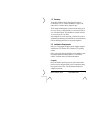
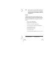
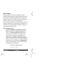
RADIO SYSTEM MANAGEMENT SOFTWARE MDS 05-3533A01, Rev. B OCTOBER 2000 Installation Notes InSite 6 Contents 1.0 2.0 3.0 4.0 5.0 6.0 Summary ....................................................................... 1 Installation Requirements ............................................. 1 Software Installation ...................................................... 6 Connecting the PC to the Radio ................................... 9 Software Start-up ........................................................ 14 Password Access ........................................................ 15 Technical Assistance Technical assistance for Microwave Data Systems products is available from our Customer Support team during normal business hours (8:00 A.M.–5:30 P.M. Eastern Time, Monday through Friday). 716-242-9600 e-mail: [email protected] Copyright Notice This manual and the software described herein is copyright © 2000 by Microwave Data Systems Inc. All rights reserved. Windows™ is a trademark of Microsoft Corporation. 1.0 Summary To use InSite, install the software from floppy disk images or CD-ROM onto a PC (see “Software Installation” on page 6), and connect the PC to a master station’s diagnostics port. The PC/master station diagnostics connection can be made in one of four ways; Directly, via dial-up modem, over a network (TCP/IP), or via a code-operated switch. These methods are described in Section 4.0, Connecting the PC to the Radio. After making the PC to radio connection, you will need to create an equipment list (instructions given in the InSite user’s manual) and load it into the InSite program before you can perform diagnostics. 2.0 Installation Requirements InSite 6 is a 32-bit program designed to run on computers equipped with Windows 95™, Windows 98™ or Windows NT™ operating software. Earlier versions of the program, designed for 16-bit operating systems and computer platforms, including Windows 3.1 and DOS, are available. Contact the factory for additional information. Computer Besides the Windows operating system, the system must include a hard drive and have adequate memory space for running and storing the program resources. Table 1 lists the minimum and preferred computer requirements. MDS 05-3533A01, Rev. B CD Installation Notes 1 Invisible place holder Table 1. Computer requirements System Item Preferred 166 MHz or faster Pentium processor Processor Minimum 75 MHz Pentium processor Microsoft Windows 95, Windows 98, or Windows NT Operating System Memory (RAM) Video 64 Megabytes (MB) 32 MB SVGA (800 x 600) high-color 16-bit display 256 colors—Some degradation in display quality will result Sound card desirable (for alert sounds) Sound 25 MB for program operation Hard Drive Space CD-ROM Drive Required. (For initial installation of the program.) Video Display InSite 6 requires an SVGA (800 x 600) video system with a high-color (16 bit) display. It will function with a 256-color display, but with some degradation in display quality. 2 CD Installation Notes MDS 05-3533A01, Rev. B Note: InSite is designed to work with Windows standard small fonts. Large fonts are not fully supported by the program. To check or change the display fonts, select Start>>Settings>>Control Panel, click on the Display icon, then select the Appearance tab. Modems A modem is required when you will be connecting your PC to the master station remotely, by telephone line or other audio circuit. While most Hayes™-compatible modems will work, the units listed below have been tested with InSite and are recommended for use with the program: • Hayes® Accura 14.4 kbps modem • Cardinal Connecta™ 56 kbps modem • US Robotics® Courier HST 14.4 kbps modem • Practical Peripherals® 14.4 kbps modem (PM14400FXSA) • Zoom® AMX 2400 bps modem • IBM ThinkPad internal modem • Xircom PCMCIA modem • Code-Operated Switches—Black Box COS-2, COS-4, COS-8 MDS 05-3533A01, Rev. B CD Installation Notes 3 Radio Equipment Radios used with InSite software must be MDS (or Adaptive Broadband) brand and be properly configured for diagnostics. InSite 6 supports only newer DSP-based products that have network-wide diagnostics capability. For older MDS radio products (DTMF-based), use InSite 5, which is also provided on the program CD. Below are the general requirements for both DTMF and network-wide diagnostics-capable radios. It is often possible to add diagnostics to a radio that was not originally shipped with diagnostics capability. For more information, contact the factory. InSite 6-compatible radios: • Network-wide diagnostics-compatible master stations, (MDS 9790 & MDS 4790) remote radios (MDS 4710A, 9710A, 2710) and spread spectrum radios (MDS 9810, 24810). Network-wide diagnostics is an option for these radios, and may or may not have been purchased for a particular radio. Use the OPT! command from a terminal window, or display the main screen using Radio Configuration Software (version 2.2 or greater), to see whether a diagnostics option has been included with the radio (“DIAGNOSTICS: ON”, as shown in following example). See the radio’s Installation and Operation Guide for instructions. Example output of OPT! command: Diagnostics:ON 4 CD Installation Notes MDS 05-3533A01, Rev. B InSite 5-compatible radios: • DTMF-compatible master stations (MDS 2100 & MDS 4100). A master station radio equipped for diagnostics will have an RS-232 connector labeled DIAGNOSTICS on the rear panel. (There may be two such connectors on some radios.) Also, the model/serial number label affixed to the radio may indicate whether or not the unit was not shipped ready for remote diagnostics. Consult the radio’s Installation and Operation Guide for details. • DTMF-compatible remote radios (MDS 2300 & MDS 4300 or MDS 960 or MDS 460). The model/serial number label on a remote radio can be examined to determine the radio’s diagnostics capability. See the radio’s Installation and Operation Guide for details. With MDS 2300/4300 as well as MDS 1000 Series radios, diagnostics capability can be confirmed by connecting a hand-held terminal to the radio’s INTERFACE connector and issuing the STAT command. Consult the radio’s Installation and Operation Guide for details. MDS 05-3533A01, Rev. B CD Installation Notes 5 3.0 Software Installation InSite can be installed from floppy disk image files downloaded from our web site (www.microwavedata.com), or from CD-ROM. You will be installing: • A file called Setup.exe, which launches the InSite installer • InSite software files • InSite on-line help file, insite.hlp • InSite Radio System Management Software manual, 2692.pdf • Network-wide Diagnostics Handbook, 3467.pdf • Adobe Acrobat Reader (for viewing or printing the manual) From Downloaded Disk Images Downloaded InSite files consist of the file Setup.exe and several floppy disk images named Data.001, Data.002, etc. To install InSite from these files, locate the Setup.exe file in your download directory and double-click on it to begin installation, which is described in πFrom CD-ROM below. If you need to install InSite on other PCs that are not connected through a network, you can copy each floppy disk image file to a single floppy disk and install from those disks. (Be sure to place the Setup.exe file on the same disk as Data.001.) Double-click on Setup.exe to launch the installer, and you will be prompted to insert each disk at the proper time. 6 CD Installation Notes MDS 05-3533A01, Rev. B Note: When installing InSite 5 or InSite 6 for the first time, you must also install the Runtime Engine and Report Generator that are included on their own directories on the program disk(s). If installing InSite from the CD, this is done automatically. From CD-ROM To install InSite from a factory-supplied CD-ROM: 1. Insert the CD-ROM disk in the CD-ROM drive. 2. When the first InSite screen appears, click on INSTALL SOFTWARE. 3. At the next screen click Install MDS SCADA Diagnostics (or other desired package). 4. At the first InSite Setup screen (Figure 1), click Install InSite 6. This presents the destination screen (not shown here) where you can specify the directory where InSite will be installed. MDS 05-3533A01, Rev. B CD Installation Notes 7 Figure 1. InSite Setup Screen 5. 8 The default directory is C:\INSITE. If this location is acceptable, click Finish. If not, choose Change and follow the instructions to change the name. CD Installation Notes MDS 05-3533A01, Rev. B NOTE: When installing InSite on a Windows NT computer, you must transfer the on-line help file (insite.hlp) and Installation and Operation Guide file (xxxxx.PDF) to a Windows directory. This directory may need to be created in Windows NT before it can be transferred. 6. Follow the remaining prompts and dialog boxes to finish the installation. When the installation is complete, the InSite program icon appears on the screen. 4.0 Connecting the PC to the Radio The PC on which InSite is installed must be connected to a master station to request and receive diagnostic data. If the PC and radio are nearby, this can be done directly, using a standard RS-232 cable. When the PC and radio are widely separated, this can be done indirectly, using modems at each end of the link, or using a TCP/IP connection over a network or the Internet. MDS 05-3533A01, Rev. B CD Installation Notes 9 Direct Connection Method In the simplest arrangement, the diagnostics computer is located in the same room as the master station, or is within 50 feet/15 meters. The computer’s RS-232 port can then be directly connected to the DIAGNOSTICS connector at the rear panel of the master station with an RS-232 cable. This arrangement is shown in Figure 2. If a DTE/DCE switch is present on the rear panel of the master station, it is normally set to DCE for this type of arrangement. Depending on the master station model, the DIAGNOSTICS port may be a 9-pin, 15-pin or 25-pin DB-style connector. Invisible place holder COMPUTER RUNNING INSITE SOFTWARE TO DIAGNOSTICS CONNECTOR TO COMPUTER'S RS-232 CONNECTOR Figure 2. Basic Direct Cabling Connection 10 CD Installation Notes MDS 05-3533A01, Rev. B Indirect Connection Method—Modem If the diagnostics computer is to be located a long distance from the master station, a modem connection may be required. In this arrangement, an audio circuit (telephone line, 2-wire/4-wire twisted pair, or microwave link) is established between the computer and the master station, and a modem is installed at each end of the link (Figure 3). If a DTE/DCE switch is present on the rear panel of the master station, it must be set to DTE when a modem is used. Invisible place holder DIAGNOSTICS CONNECTOR COMPUTER RUNNING INSITE SOFTWARE TO COMPUTERS RS-232 PORT MASTER STATION REAR PANEL (TYPICAL) STANDARD RS-232 CABLE STANDARD RS-232 CABLE TO TELEPHONE LINE DIAL-UP MODEM TO TELEPHONE LINE DIAL-UP MODEM Figure 3. Basic Modem Connection MDS 05-3533A01, Rev. B CD Installation Notes 11 Indirect Connection Method—Internet (TCP/IP) Access Network-wide diagnostics information can be accessed over a network or the Internet using a Remote Access Server (RAS), as shown in Figure 4. The RAS will serve as a media converter from a serial port (RS-232-type) to an Ethernet multi-drop interface. The RAS will also convert the serial protocol to a TCP/IP protocol suitable for Internet connectivity. Contact the factory for additional information on configuring the Remote Access Server. Code-Operated Switch Method A code-operated switch (COS) connection is required at a site with co-located Network-wide capable Master stations. This device avoids addressing problems that occur between one or more Master radios using a single line back to the central site for diagnostics. The COS may also be used in combination with a Dial-up modem. InSite supports COS units such as Black Box COS-2, COS-4, and COS-8. Refer to the InSite user guide for COS setup information. Note for Using InSite 5 with older (DTMF) radios MDS 2100 and 4100 master stations shipped from the factory are normally set for 1200 bps diagnostics communication speed. The speed can be changed if necessary; see the radio’s Installation and Instruction Guide for details. 12 CD Installation Notes MDS 05-3533A01, Rev. B Invisible place holder RTU RTU RTU TO TO DATA PORT DIAGNOSTICS PORT DTYPE ROOT MASTER STATION ROOT NODE SCADA HOST COMPUTER REMOTE ACCESS SERVER ETHERNET TCP/IP DIAGNOSTICS COMPUTER RUNNING InSite INTERNET Figure 4. Network-wide Diagnostics Served via the Internet MDS 05-3533A01, Rev. B CD Installation Notes 13 5.0 Software Start-up To start InSite, select it from Windows’ Start >> Programs menu. After the program loads, you will see the Main Menu screen (Figure 5). Invisible place holder Figure 5. Main Menu Screen 14 CD Installation Notes MDS 05-3533A01, Rev. B You will need to set up an equipment list before performing diagnostics. An equipment list is a database of information on radios in a system; it configures polling options for diagnostics and sets up the NetworkView screens. Until you create a list, InSite loads the Default Equipment List, default.equ, which will provide basic functionality for most systems. See the InSite Installation and Operation Guide. Several sample equipment lists are installed on your hard drive as part of the InSite installation process. To display the Guide, select Help>>On-line Help. On the displayed Contents page, locate and click on the button labeled “InSite 5 Electronic Manual.” Or locate the file 2692.pdf in the Windows directory and double-click on it. In either case, the Guide is displayed using Adobe Acrobat Reader. The Guide’s table of contents and index consist of hot links that you can click on to display a particular topic; cross-references within the Guide are also hot links. 6.0 Password Access You may also want to enable passwords. When passwords are enabled, InSite displays a graphical user interface that makes it easy for inexperienced users to perform diagnostics, but limits access to the system setup and equipment list screens. Experienced users, however, can navigate directly to the screen they want, create or edit equipment lists, and change system settings. See the InSite Installation and Operation Guide for more information on system settings and passwords. MDS 05-3533A01, Rev. B CD Installation Notes 15 NOTES 16 CD Installation Notes MDS 05-3533A01, Rev. B 175 Science Parkway, Rochester, New York 14620 General Business: +1 (716) 242-9600 FAX: +1 (716) 242-9620 www.microwavedata.com