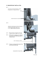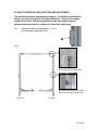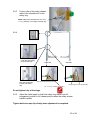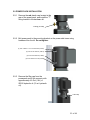
1
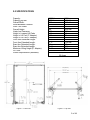
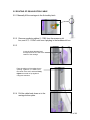
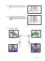
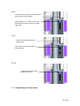
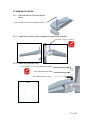
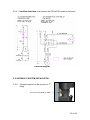
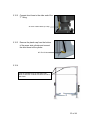
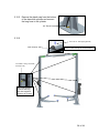
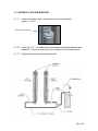
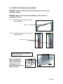
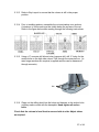
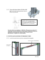
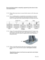
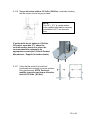
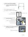
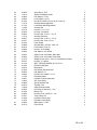
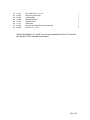
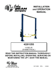
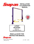
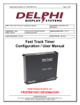
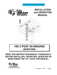
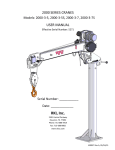
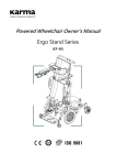
INSTALLATION
and
d OPERATION
MANUAL
10K ALL-IN-ONE 2 POST V-SERIES
42010DSA 42010VSA
READ THIS INSTRUCTION MANUAL THOROUGHLY BEFORE
INSTALLING, OPERATING, SERVICING OR MAINTAINING THE
LIFT. SAVE THIS MANUAL.
309 EXCHANGE AVENUE,
CONWAY, ARKANSAS, 72032
TEL: 501-450-1500 FAX: 501-450-1585
DEC 2011 REV. A 6-3858
Table of Contents
1.0 SAFETY AND OPERATING INSTRUCTIONS ............................................... 3
2.0 SPECIFICATIONS .......................................................................................... 5
3.0 PACKING LIST............................................................................................... 6
3.1 MAIN STRUCTURAL COMPONENTS ....................................................... 6
3.2 ACCESSORY BOX ..................................................................................... 6
4.0 INSTALLATION REQUIREMENTS AND TOOLS .......................................... 7
4.1 FOUNDATION ............................................................................................ 7
4.2 TOOLS ........................................................................................................ 7
5.0 INSTALLATION INSTRUCTIONS .................................................................. 8
5.1 UNPACKING PROCEDURE ....................................................................... 8
5.2 BAY LAYOUT ............................................................................................. 9
5.3 CROSSMEMBER INSTALLATION .......................................................... 10
5.4 SAFETY SHUT-OFF BAR INSTALLATION ............................................. 10
5.5 ROUTING OF EQUALIZATION CABLE ................................................... 14
5.6 ARM INSTALLATION ............................................................................... 17
5.7 ARM RESTRAINT INSTALLATION ......................................................... 18
5.8 SAFETY RELEASE CABLE ROUTING AND ADJUSTMENT ................. 19
5.9 POWER PACK INSTALLATION .............................................................. 21
5.10 HYDRAULIC SYSTEM INSTALLATION ................................................ 22
5.11 HYDRAULIC SYSTEM BLEEDING ........................................................ 25
5.12 TOWER POSITIONING AND ANCHORING ........................................... 26
5.13 POSITION AND ANCHORING OF REMAINING TOWER ...................... 28
5.14 SAFETY SHUT-OFF BAR ADJUSTMENT ............................................. 31
5.15 FINAL CHECK OF ASSEMBLED LIFT .................................................. 32
5.16 OPERATION TEST WITH VEHICLE ...................................................... 33
6.0 LIFT MAINTENANCE GUIDELINES ............................................................ 34
6.1 SAFETY INSTRUCTIONS ........................................................................ 34
6.2 PERIODIC MAINTENANCE...................................................................... 34
7.0 SAFETY AWARENESS ............................................................................... 35
8.0 Parts List ..................................................................................................... 36
8.1 HYDRAULIC SYSTEM ............................................................................. 41
8.2 POWER PACK PARTS LIST:................................................................... 42
9.0 Available Accessories ................................................................................ 44
2 of 44
1.0 SAFETY AND OPERATING INSTRUCTIONS
1. When using this lift, basic safety precautions should always be followed,
including the following.
2. Read all instructions in this manual and on the lift thoroughly before
installing, operating, servicing or maintaining the lift.
3. Inspect lift daily. Do not operate if it malfunctions or problems have been
encountered.
4. Never attempt to overload the lift. The manufacturer’s rated capacity is
shown on the identification label on the power side column. Do not
override the operating controls or the warranty will be void.
5. Before driving vehicle between the towers, position the arms to the drivethrough position to ensure unobstructed clearance. Do not hit or run over
arms as this could damage the lift and/or vehicle.
6. Only trained and authorized personnel should operate the lift. Do not allow
customers or bystanders to operate the lift or be in the lift area.
7. Position the lift support pads to contact the vehicle manufacturers
recommended lifting points. Raise the lift until the pads contact the
vehicle. Check pads for secure contact with the vehicle. Check all arm
restraints and insure they are properly engaged. Raise the lift to the
desired working height.
8. Some pickup trucks may require an optional truck adapter to clear running
boards or other accessories.
9. NOTE: Always use all 4 arms to raise and support vehicle.
10. Caution! Never work under the lift unless the mechanical safety
locks are engaged.
11. Note that the removal or installation of some vehicle parts may cause a
critical load shift in the center of gravity and may cause the vehicle to
become unstable. Refer to the vehicle manufacturer’s service manual for
recommended procedures.
12. Always keep the lift area free of obstruction and debris. Grease and oil
spills should always be cleaned up immediately.
13. Never raise vehicle with passengers inside.
14. Before lowering check area for any obstructions.
15. Before removing the vehicle from the lift area, position the arms to the
drivethru position to prevent damage to the lift and /or vehicle.
16. Do not remove hydraulic fittings while under pressure.
3 of 44
For additional safety instructions regarding lifting, lift types, warning labels,
preparing to lift, vehicle spotting, vehicle lifting, maintaining load stability,
emergency procedures, vehicle lowering, lift limitations, lift maintenance, good
shop practices, installation, operator training and owner/employer
responsibilities, please refer to “Lifting It Right” (ALI/SM) and “Safety Tips”
(ALI/ST).
For additional instruction on general requirements for lift operation, please refer
to “Automotive Lift-Safety Requirements For Operation, Inspection and
Maintenance” (ANSI/ALI ALOIM).
Installation shall be performed in accordance with ANSO/ALI ALIS, Safety
Requirements for Installation and Service of Automotive Lifts.
ATTENTION! This lift is intended for indoor installation only. It is
prohibited to install this product outdoors. Operating environment
temperature range should be 41 – 104 °F (5 – 40 °C). Failure to
adhere will result in decertification, loss of warranty, and possible
damage to the equipment.
4 of 44
2.0 SPECIFICATIONS
Capacity:
Capacity per arm:
Overall Width:
Width Between Columns:
Drive-Thru Width:
Overall Height:
Under bar Clearance:
Height to Lowered Lift Pads
Height to Lift Pad (3” Adapter):
Height to Lift Pad (6” Adapter):
Front Arm Retracted Length:
Front Arm Extended Length:
Rear Arm Retracted Length:
Rear Arm Extended Length:
Maximum Lifting Height (6” Adapter):
Lift Time:
Power Requirements (Standard):
Figure 1 - Front View
10000 lbs.
2500 lbs
135”
110”
88”
144”
140”
4 ½”
7 ½”
10 ½”
22 ½”
45 ½”
38”
59 ½”
79 ¼”
4536 kg
1134 kg
3429 mm
2794 mm
2235 mm
3658 mm
3556 mm
114 mm
191 mm
267 mm
572 mm
1158 mm
965 mm
1511 mm
2013 mm
45 seconds
230 Volts AC, 1 Ph., 60 Hz.
20 Amps
Figure 2 - Top View
5 of 44
3.0 PACKING LIST
The complete lift is contained in two (2) packages:
1. The main structural components are packed in a steel frame.
2. The remaining parts are packed in an accessory box.
3.1 MAIN STRUCTURAL COMPONENTS
1pc. - Power side tower and carriage assembly
1pc. - Slave side tower and carriage assembly
1pc. - Crossmember
1pc. - Actuator Bar w/ foam
3.2 ACCESSORY BOX
4pcs. - Locking Arm Assembly w/arm pins
2pcs. - Safety Covers w/Decals
1pc. - Hardware Package w/Packing List
1pc. - Actuator Extension
1pc. - Actuator Mounting Bracket
1pc. - Power Pack
4pc. - Arm Restraint
1pc. - Safety Release Cable
1pc. - Hydraulic Hose (Long)
1pc. - Hydraulic Hose (Short)
2pcs. - Equalizing Cable w/Hex Nuts
1pc. - ALI manual “Lifting It Right”
1pc. - Automotive Lift Safety Tips
1pc. - Automotive Lift, Operation, Inspection and Maintenance manual
1pc. - “ALI” Quick Reference Guide
1pc. - Owner’s manual
1pc. - Safety Shut-off Microswitch Assembly (Components)
6 of 44
4.0 INSTALLATION REQUIREMENTS AND TOOLS
4.1 FOUNDATION
IMPORTANT: It is the user’s responsibility to provide a satisfactory installation
area for the lift. Lifts should only be installed on level concrete floors with a
minimum thickness of four and a quarter inches (4¼”) or 108 mm. Concrete must
have a minimum strength of 3000 psi or 21 MPa and should be aged thirty (30)
days prior to installation. Please consult the architect, contractor or engineer if
doubt exists as to the strength and feasibility of the floor to enable proper lift
installation and operation.
It is the user’s responsibility to provide all wiring for electrical hook-up prior to
installation and to insure that the electrical installation conforms to local building
codes. Where required, it is the user’s responsibility to provide an electrical
isolation switch located in close proximity to the lift that will enable emergency
stop capability and isolate electrical power from the lift for any servicing
requirements.
4.2 TOOLS
a. 16ft. Measuring Tape
b. Chalk Line
c. Rotary Hammer Drill
d. 3/4” diameter Masonry Drill Bit
e. Hammer
f. SAE Wrenches and Ratchet Set
g. 2ft. Level
h. 4ft. Level
i. Crow Bar
j. 12ft. Step Ladder
k. Side Cutters
l. Screwdrivers
m. 4” x 4” Wooden Blocks (for unpacking)
n. Wherever LOCTITE symbol is shown, apply LOCTITE #242 on required
fasteners. If fasteners are removed reapply LOCTITE before re-installing.
7 of 44
5.0 INSTALLATION INSTRUCTIONS
When the lift arrives on site:
Read the owner’s manual and make sure the installation instructions are
fully understood.
Check for any freight damages.
Check the contents of the accessory and hardware boxes to make sure no
parts are missing.
Gather all the tools listed above.
5.1 UNPACKING PROCEDURE
5.1.1 Important! Place the main structural components on wooden blocks so
that the steel shipping frames can be removed.
5.1.2 Remove the plastic wrapping.
5.1.3 Remove the crossmember, and the actuator bar.
5.1.4 Unbolt the steel shipping frames.
5.1.5 Lay each tower on the floor with the carriage side up.
5.1.6 Check the installation area for obstructions. (Lights, Heating Ducts,
Ceiling, Floor Drains, etc.)
8 of 44
5.2 BAY LAYOUT
5.2.1 Prepare the bay by selecting the location of the lift relative to the walls.
5.2.2 Clear the installation area of all packaging materials to avoid trip hazards.
5.2.3 Measure midpoint of door.
5.2.4 Using measuring tape scribe two
arcs, equal distance from the
midpoint.
5.2.5 The centerline of the lift occurs
between the intersection of the
arcs and the midpoint of the door.
Note: Leave any additional room for
any desired aisle or work area.
Recommended minimum clearance
around lift is three feet (3 ft) and
above lift is four inches (4”).
Ensure clearance conforms to local
building and fire codes.
Figure 3. Chalk line
5.2.6 Measure the specified distance (126”) to draw a second chalk line at 90°
for locating the lift towers. Refer to Figure 3.
5.2.7 The lift is centered between the door and the walls of the area.
129” (3277 mm)
97 7/8”
(2486 mm)
Figure 4. Bay Layout
9 of 44
5.3 CROSSMEMBER INSTALLATION
5.3.1 Install the cross member bracket to the two towers. While they are still
on the floor.
Flat Washer, ½”ID SAE (6-0248)
10K Symmetric Pulley
Assy (2-2318)
Hex Nut, ½”-13 UNC (6-0035)
Lock Washer, ½”ID (6-0059)
½”-16UNC x 1 ½” lg. hex head bolts (6-0291)
5.3.2 Stand towers in the position shown.
Power Tower
Slave Tower
10 of 44
5.3.3 Using a stepladder, insert
screwdrivers into brackets
and place crossmember on
top of screwdrivers.
5.3.4 Locate crossmember to the correct holes in the bracket and install
fasteners.
½”-13 UNC Flat Washer (6-0063)
½”-13 UNC 1” LG. HEX BOLT (6-0045)
1/2” Lock Washer (6-0059)
½”-13 UNC Hex Nuts (6-0035)
11 of 44
5.4 SAFETY SHUT-OFF BAR INSTALLATION
The safety shut off will disconnect the power to the power pack when an
obstruction touches the padded bar or the carriages reach their maximum height.
The safety shut off switch is factory pre-wired.
5.4.1 Attach the Actuator Mounting Bracket (1-1378) to the crossmember
¼” NC hex nut (6-0032)
¼”ID lockwasher (6-0056)
Actuator Mounting Bracket (1-1378)
Note: Install bracket on
Slave side.
¼” NC x 3/4” lg. hex head bolt (6-0178)
5.4.2 Attach the Actuator Bar to the Actuator Mounting Bracket.
¼” NC x 1 ½” lg. hex head bolt (6-0205)
¼”ID lockwasher (6-0056)
Actuator Bar
¼” NC hex nut (6-0032)
5.4.3 Slide Safety Shut-Off Microswitch
Assembly over the open end of actuator
bar.
Microswitch Assembly
12 of 44
Bolt the assembly to the crossmember.
¼” NC hex nut (6-0032)
¼”ID lockwasher (6-0056)
¼” NC x 1” lg. hex head bolt (6-0008)
13 of 44
5.5 ROUTING OF EQUALIZATION CABLE
5.5.1 Manually lift the carriages to the first safety latch.
5.5.2 Remove equalizing cables (1-1786) from the accessory kit
box, and 8 ½”- 13UNC nuts from a polybag in the hardware kit box.
5.5.3
Insert the short threaded stud
through the 9/16”dia. hole at the
bottom of the carriage.
Pass the cable until it reaches the top
opening. Tighten a ½”-13UNC nut to
the center of the stud, and then firmly
tighten a second nut up against it
using two wrenches.
5.5.4 Pull the cable back down on to the
carriage bottom plate.
14 of 44
5.5.5 At the bottom of the column, remove the
hitch pin, pulley pin and pulley from the base
plate.
5.5.6 Route equalizing cable around pulley and
reassemble the pulley to the base plate.
IMPORTANT – Hitch pin must be installed
securely.
5.5.7 Route Cable as shown.
Route around pulley.
Route Up through column.
Insert stud through top of carriage.
15 of 44
5.5.8
Use a wrench to hold the top of the threaded
stud to prevent it from rotating.
Hand tighten (2) ½”-13 UNC nuts onto the
threaded stud enough to remove all visible
cable slack
5.5.9
Hold the top of the threaded stud
using wrench.
Tighten the first nut approximately 1 ½”
to tension cable.
5.5.10
Tighten the second nut firmly
against the first one.
5.5.11 Repeat steps for other cable.
16 of 44
5.6 ARM INSTALLATION
5.6.1 Remove the Arm Pins from all four
Arms.
5/16”-18UNC x 3/4”LG. hex head bolt (6-0423)
5.6.2 Install the four arms on the carriages by inserting the arm pins.
5/16”-18UNC x 3/4”LG. hex head bolt
5.6.3 Install Arm Restraint Gear.
5/16”-18UNC x 1 ¼” LG. hex head bolt (6-2059)
5/16” Flat Washers (6-0295)
Arm Restraint Gear (1-2618)
Front
Orientation of Gears.
17 of 44
5.7 ARM RESTRAINT INSTALLATION
5.7.1
Insert arm lock handle weldment (1-2914)
through holes in carriage weldment.
Loosen the two 5/16” hex bolts
5.7.2
Adjust arm restraint gear so that lock engages
smoothly through entire range of arm
motion. Tighten both 5/16 hex bolts.
5.7.3
Repeat above steps for all arms.
5.7.4
Slide arm lock spring over outboard
leg of arm lock handle (leg which is
nearest tower).
Arm Lock Spring (1-2942)
5.7.5
Hammer a spring retainer cap to the
end of the arm lock leg.
Spring Retainer Cap (6-3086)
18 of 44
5.8 SAFETY RELEASE CABLE ROUTING AND ADJUSTMENT
The mechanical safety automatically engages. To release the mechanical
safety, you must first raise the lift approximately 2”, then pull the safety
release lever down. This disengages the power side safety dog and
activates the safety cable to release the slave side safety dog.
5.8.1
Install the safety release handle (1-1113)
onto the power side safety dog.
5.8.2
Start Routing here on slave side.
Pull cable out through the opening in
tower and route under large pulley.
Power Side
Slave Side
19 of 44
5.8.3
Fix the collar of the safety release
cable to the shoulder bolt on the
safety dog.
NOTE: Make sure shoulder bolt, 3/8” dia. x
1 ½” lg. (6-0801), is lock tight to safety dog.
5.8.4
Guide the cable up
under the large pulley
on the power side.
Over the small pulley
towards the safety
dog.
Power Side
Slave Side
Wrap around the Thimble (6-2074)
Clamp using wire rope clips (6-2060)
3/8” x 1 1/2” lg. shoulder bolt (6-0801)
Do not tighten fully at this stage.
5.8.5
Adjust the cable length so that both safety dogs travel from full
engagement position to full release position when the safety release
handle is pulled.
Tighten both wire rope clips firmly when adjustment is completed.
20 of 44
5.9 POWER PACK INSTALLATION
5.9.1 Remove the red plastic cap located at the
rear of the power pack, and install the "T"
fitting located in the hardware kit.
T-Fitting (6-1506)
5.9.2 Bolt power pack to the mounting bracket on the power side tower using
hardware from the kit. Do not tighten.
(4) 5/16”-18UNC x 1”LG. hex head bolts (6-0293)
(4) 5/16” ID lock washers (6-0674)
(4) 5/16” ID flat washers (6-0295)
(4) 5/16”-18UNC hex nuts (6-0294)
5.9.3 Remove the filler cap from the
powerpack and fill the reservoir with
approximately 4.5 Gal. (18L) of
ISO32 hydraulic oil (10 wt. hydraulic
oil).
Filler Cap
21 of 44
5.9.4 A certified electrician must connect the 230Volt/1Ph power to the motor.
Electrical Diagram
5.10 HYDRAULIC SYSTEM INSTALLATION
5.10.1 Connect long hose to the top port on “T”
fitting.
45° End of Long Hose (2-1486)
22 of 44
5.10.2 Connect short hose to the other end of the
“T” fitting.
45° End of Short Hose (2-1230)
5.10.3 Remove the plastic cap from the bottom
of the power side cylinder and connect
the short hose to the cylinder.
90° End of Hose
5.10.4
Loop the hydraulic hose up the power side
tower, across the overhead and down the slave
side tower.
23 of 44
5.10.5 Remove the plastic cap from the bottom
of the slave side cylinder and connect
the long hose to the cylinder.
90° End of Hose
5.10.6
#10 x 3/8” LG. Self Tapping (6-0169)
Tube clamp (6-1547)
Place 3 tube clamps on crossmember.
1/4”-20UNC x 3/8”lg. round head
screws (6-1353)
Use 6 tube clamps
to secure the long
and short hydraulic
hoses to the Towers.
24 of 44
5.11 HYDRAULIC SYSTEM BLEEDING
5.11.1 Crack the bleeder valve located at the top of both cylinders
(approx. ¼ turn)
BLEEDER VALVE (6-3666)
5.11.2 Power up 2”-3”. You should hear air escaping around the bleeder valve.
Repeat 3 – 4 times or until only oil is coming out of the bleeder valve.
5.11.3 Tighten the bleed screw and lower the lift.
25 of 44
5.12 TOWER POSITIONING AND ANCHORING
WARNING! Failure to follow these instructions may cause an unsafe
operating condition.
WARNING! Before proceeding with installation, review Section 4:
Installation & Tools.
5.12.1 Determine which column is higher
using a 4ft level.
Place 4 ft. Level.
5.12.2 Check if high column is level in the
vertical position.
Place 2 ft. Level.
Note: Use shims under baseplate
to level the column.
Ensure that the base
plate is completely
supported by shims
including near the
center where it does not
contact the floor.
26 of 44
5.12.3 Refer to Bay Layout to ensure that the column is still in the proper
position.
5.12.4 Prior to installing anchors, assemble the nut and washer onto anchors.
A minimum of six threads must be visible below the surface of the nut.
Refer to the figure below while reading through the following instructions.
5.12.5 Using a ¾” concrete drill bit and rotary hammer drill, drill ¾” holes for the
anchor bolts on the high side column. Drill through the concrete floor. (In
case longer anchors are required, supplied anchors can be hammered
through concrete).
Drill
5.12.6 Clean out the drilling dust from the holes and hammer in the anchor bolts
untilthey make contact with the baseplate. Hand tighten all anchor
bolts.
Check that the column is level front to rear and side to side. Adjust shims
as required.
27 of 44
5.12.7 Torque all anchor bolts to 150 ft-lbs. (203
Nm), continually checking that the column is
level as you proceed.
NOTE:
The 3/4” 5 ½” lg. wedge anchor
bolts supplied must have a minimum
embedment of 3¼” into concrete
floor.
If anchor bolts do not tighten to 150 ft-lbs. OR project more than 2 ¼”
above the concrete surface due to floor slope, the concrete should be
replaced by an appropriate concrete pad. (Consult Product
Manufacturer / Supplier for further details).
5.13 POSITION AND ANCHORING OF REMAINING TOWER
5.13.1 Level the low side column by shim underneath the baseplate.
Use 4 ft. level on cross member.
Use 2 ft level
on column.
28 of 44
Ensure that the baseplate is completely supported by shims where it does
not contact the floor.
5.13.2 Refer to Bay Layout above to ensure that the column is still in the proper
position.
5.13.3 Prior to installing anchors, assemble the nut and washer onto anchors.
A minimum of six threads must be visible below the surface of the nut.
Refer to the figure below while reading through the following instructions.
5.13.4 Using a ¾” concrete drill bit and rotary hammer drill, drill ¾” holes for the
anchor bolts on the high side column. Drill through the concrete floor. (In
case longer anchors are required, supplied anchors can be hammered
through concrete).
Drill
5.13.5 Clean out the drilling dust from the holes and hammer in the anchors
until they make contact with the baseplate. Hand tighten all anchor
bolts.
Check that the column is level front to rear and side to side. Adjust
shims as required.
29 of 44
5.13.6 Torque all anchor bolts to 150 ft-lbs. (203 Nm), continually checking
that the column is level as you proceed.
NOTE:
The 3/4” 5 ½” lg. wedge anchor
bolts supplied must have a minimum
embedment of 3¼” into concrete
floor.
If anchor bolts do not tighten to 150 ft-lbs.
OR project more than 2 ¼” above the
concrete surface due to floor slope, the
concrete should be replaced by an
appropriate concrete pad. (Consult Product
Manufacturer / Supplier for further details).
5.13.7 Verify that the entire lift is level both
horizontally and vertically to ensure optimum
lifting performance. NOTE: Perform a
monthly inspection and torque all anchor
bolts to 150 ft-lbs. (203 Nm).
30 of 44
5.14 SAFETY SHUT-OFF BAR ADJUSTMENT
5.14.1 When the lift is fully installed, leveled and
operational, extend the carriages to their full
upper limit.
5.14.2 Lower the carriages about ¼” to ½”.
5.14.3 Attach a ¼ bolt and nut to actuator extension.
¼” NC hex nut (6-0032)
Actuator extension (1-1379)
¼” NC x 2” lg. hex bolt (6-0741)
Actuator Bar
5.14.4 Bolt the Actuator Extension onto the
open end of actuator bar.
Actuator Extension
¼” NC x 1 ¼” lg. hex head bolts (6-0027)
¼” ID lockwashers (6-0056)
¼” NC hex nuts (6-0032)
5.14.5 Adjust the ¼” NC x 2” lg. hex bolt so that the end
of the bolt is in contact with the carriage. Tighten
the ¼” NC hex nut on the bolt.
Hex bolt in Contact with Carriage.
31 of 44
5.15 FINAL CHECK OF ASSEMBLED LIFT
1. Final dimension check after anchoring.
____
2. Check for hydraulic leaks.
____
3. Ensure cables are properly routed and free from obstructions. ____
4. Check jam nuts on cables are tightened.
____
5. Check that LOCTITE has been applied to all hardware
where required.
____
6. Check adjustment of safety release cable to ensure both sides
working properly.
____
7. Re-check level of towers.
____
8. Check torque of anchor bolts.
____
9. Check all fasteners, tighten if necessary.
____
10. Check shut off at top of stroke to ensure lift shuts off.
____
11. Check proper operation of arm restraints.
____
12. Operate lift to full stroke then lower to ground while checking
for proper functionality.
____
13. Ensure Customer Care Kit is complete and given to operator. ____
a. Operation Manual
____
b. ANSI / ALI Lift It Right Manual
____
c. ANSI / ALI Safety Tip Card
____
d. ANSI / ALI ALIS Safety Requirements for Installation
and Service of Automotive Lifts
____
e. ANSI / ALI Quick Reference Guide
____
14. Train end user on operation of lift.
____
32 of 44
5.16 OPERATION TEST WITH VEHICLE
1. Lower lift to ground.
2. Drive vehicle on to lift and locate the arms as per the “Lift it Right” manual.
3. Raise lift to and lower onto 3-4 lock positions during full rise to ensure all
locks are working correctly.
4. Re-adjust cables if necessary while vehicle is on.
5. Check lowering speed and smooth decent rate.
6. Lower lift to ground and drive vehicle off lift.
If any problems occur during the final checkout or operation of the lift please
contact customer service at 1-800-268-7959
33 of 44
6.0 LIFT MAINTENANCE GUIDELINES
6.1 SAFETY INSTRUCTIONS
Read operating and safety manuals before using any lift.
Do not operate a lift that has been damaged or is in disrepair.
Proper inspection and maintenance is necessary for safe operation.
6.2 PERIODIC MAINTENANCE
DAILY:
1.
2.
3.
4.
5.
Check all hydraulic lines and fittings for pinch points , damage , cracks or leaks
Check all electrical wiring for pinch points , cracks or damage
Check all moving parts for uneven or excessive wear
Repair or replace all damaged, defective, worn or broken components immediately.
Check the telescopic arms for movement. Clean any grease or oil from the lifting
adapters.
6. Raise and lower the lift at the beginning of each shift, without a vehicle on, to verify the lift
is leveled and operating properly.
EVERY TWO MONTHS:
1.
2.
3.
4.
5.
Clean and re-grease slide block channels inside of both columns
Grease arm pins
Lubricate safety dogs and check safety release cable adjustment
Check arm restraints and lubricate
Check anchor bolts and re-torque if required
EVERY FOUR MONTHS:
1. Dismantle and clean inner arms
2. Lubricate cable pulleys
3. Check equalizing cable adjustment
EVERY YEAR:
1. Inspect lift as per Automotive Lift Operation, Inspection and Maintenance (ALOIM)
EVERY TWO YEARS:
1. Change hydraulic fluid
LUBRICATION:
Where grease is required > multi-purpose lithium grease
Where lubricating oil is required > multi-purpose SAE 30 lubricating oil
Where hydraulic oil is required > ISO 32 10W - non detergent hydraulic oil
NOTE: If the lift locks, while in the fully raised position this will indicate that the
hydraulic system has not been inspected or maintained as recommended.
This is a safety back-up system. If you are unclear call your local
representative immediately.
34 of 44
7.0 SAFETY AWARENESS
AUTOMOTIVE LIFT INSTITUTE (ALI)
35 of 44
8.0 PARTS LIST
36 of 44
Item#
1
2a
2b
3
4
5
6
7
8
9
10
11
12
13
14
15
16
17
18
19 *
20 *
21
22
23
24
25
26
27
28
29
30
31
32
33
34
35
36
37
38
39
40
41
42
43
44
45
Part #
4-1010
2-2835
2-2834
2-2323
4-1011
4-1141
2-2296
2-2300
3-0920
6-0030
3-0924
2-2282
2-2279
1-2618
2-1594
6-0295
6-0423
6-2059
1-3279
1-3280
2-1580
2-0772
1-1887
1-1898
6-1841
6-0248
6-0059
6-0035
6-0291
1-2337
6-0808
2-1901
6-0169
6-0206
1-0415
2-1251
6-0978
1-1626
6-0738
1-1623
1-1116
6-0801
1-1113
6-1135
1-1115
1-2914
Description
TOWER WELDMENT, POWER SIDE
SYMMETRIC CROSSMEMBER BRKT
SYMMETRIC CROSSMEMBER BRKT
CROSSMEMBER
TOWER WELDMENT, SLAVE SIDE
CARRIAGE WELDMENT
OUTER TUBE WELDMENT RS
OUTER TUBE WELDMENT LS
ARM WELDMENT
Hex Bolt, 3/8 UNC x ¾” LG.
ASYM LONG INNER
INTERMEDIATE ARM WELDMENT
INNER ARM WELDMENT
ARM RESTRAINT GEAR
Arm Pin
Flat Washer, 5/16 I.D.
Hex Bolt, 5/16”-18UNC x ¾” LG.
Hex HD. Bolt, 5/16-18UNC x 1 1/4" LG.
Stack Pad Assembly ½”
Stack Pad Adapter 3”
Stack Pad Adapter 6”
Glide Block
Pin, Cable Equalization
2-Post Pulley
Hitch Pin, 1/8” DIA.
Flat Washer, ½” ID SAE
Lock Washer, 1/2 "
NUT, 1/2-13 UNC, HEX
Hex Bolt, ½”-13 UNC x 1 ½” LG.
Safety Pin
Flat Washer, 51/64” ID x 1” OD x 1/16” THK.
Safety Dog Weldment, Power Side
SELF-TAPPING SCREW, #10 X 3/8 LG
Shoulder Bolt, 3/8” DIA. X 1” LG.
Safety Pulley
Crossmember Pulley Shaft
Cotter Pin, 1/8” DIA. X 1 ½” LG.
Crossmember Pulley Pipe, 1 ¾” LG.
Flat Washer, ¾” ID
Crossmember Pulley Pipe, ½” LG.
Safety Cable Pulley
Shoulder Bolt, 3/8” x 1 ½” LG.
Safety Release Handle
Plastic Knob
Safety Spring
Arm Lock Handle Weldment
Qty.
1
1
1
1
1
2
1
1
2
4
2
2
2
4
4
12
4
8
4
2
2
8
2
6
2
16
16
16
8
2
4
2
6
3
2
2
4
2
26ll
4
3
2
1
2
2
4
37 of 44
46
47
48
49
50
51
52
53
54
55
56
57
58
59
60
61
62
63
64
65
66
67
68
69
70
71
72
73
74
75
76
77
78
79
80
81
83
84
85
86
87
88
6-2445
1-2012
6-0060
6-0056
6-1353
1-1378
2-1143
1-1380
6-0178
6-0032
6-0205
1-1379
6-0027
6-0741
6-1404
6-0069
6-0674
6-0294
6-0062
0-0203
0-0204
6-1379
6-0737
6-1134
6-1403
6-0916
6-1466
6-0063
6-0045
1-1786
3-0621
1-2942
6-3086
6-2074
1-2058
6-2055
6-1506
6-0293
6-1547
2-1486
2-1230
6-2095
6-1510
Snap Ring ¾” EXT
Stack Pad Adapter Holder
Flat Washer, 1/4 I.D.
Lock Washer, 1/4 I.D.
Round HD. MACH. Screw 1/4-20 x 3/8" LG.
Actuator Mounting Bracket
Limit Switch Mounting Bracket
Actuator Bar
Hex Bolt, ¼” x ¾” LG.
Hex Nut, 1/4-20UNC
Hex HD. Bolt ¼” NC x 1 ½” LG.
Actuator Extension
Hex HD. Bolt ¼” NC x 1 ¼” LG.
Hex HD. Bolt ¼”NC x 2” LG.
Foam Guard
Shoulder Bolt, 3/8” DIA. X 5/8” LG.
Lock Washer, 5/16 I.D.
Hex Nut, 5/16-18UNC
Flat Washer, 3/8” ID SAE
Safety Cover c/w Decals, Slave Side
Safety Cover c/w Decals, Power Side
Wedge Anchor 3/4 x 5 1/2" LG. (c/w Washers & Nuts)
Hex Nut, ¾”-10UNC
SELF TAPPING SCREW, #12 X 1/2 LG
Electrical Utility Box
Microswitch
6/32 Screw (Electrical Box)
Flat Washer, 1/2
Hex Bolt,1/2-13UNC X 1” LG.
Equalizing Cable
Hydraulic Cylinder Assembly
Arm Lock Spring
Spring Retainer Cap
Thimble, 5/32”
Safety Release Cable
Power Pack, 208-230 V, 1 PH
Branch Tee
Hex Bolt, 5/16”-18UNC x 1” LG.
Tube Clamp, 5/8
Hydraulic Hose (Long)
Hydraulic Hose (Short)
Male Nipple, ¼” NPT
Flow Control
4
2
4
10
10
1
1
1
1
7
1
1
2
1
1
2
6
6
4
1
1
10
10
4
1
1
2
8
8
2
2
4
4
2
1
1
1
4
8
1
1
2
2
38 of 44
91
92
93
94
95
96
97
98
6-1173
2-0872
6-0000
6-3039
6-1767
6-1111
2-2318
6-0008
Elec. Cable 12/3 x 117 LG.
Safety Dog, Slave Side
Grease Nipple
Operations Decal
Capacity Decal
Serial Plate
9K Symmetric Equalizing Pulley Assembly
Hex Bolt, ¼” x 1” LG.
1
1
4
1
1
1
2
2
* Stack Pad Adapters (3” and 6”) do not come standard with the “D” series lift.
See Section 9.0 for available Accessories.
39 of 44
8.1 HYDRAULIC SYSTEM:
40 of 44
Item
Part #
Description
1
6-2055
6-2665
6-3039
6-0294
6-0674
6-2095
6-3666
6-4083
6-1510
6-3162
6-3914
6-0295
6-0293
6-1506
2-1486
2-1230
3-062101
Power Pack, 208-230V, 1 PH
Power Pack, 208-230V, 3 PH
“Lift Operation” Decal
Hex Nut, 5/16”-18 UNC
Lock Washer, 5/16” I.D.
Male Nipple, ¼” NPT
Bleeder Valve (Holmac)
Bleeder Valve (HWF Eagle)
Flow Control
Gland & Piston Seal Kit (Holmac Cylinder)
Gland & Piston Seal Kit (HWF Eagle Cylinder)
Flat Washer, 5/16” I.D.
Hex Bolt, 5/16”-18 UNC x 1” LG.
Branch Tee
Hydraulic Hose (Long)
Hydraulic Hose (Short)
Cylinder Assembly (Not INCL. Flow Control)
2
3
4
7
8
9
11
12
13
14
15
16
*
*
*
*
*
*
*
*
6-1575
2-1130
1-1369
6-0008
6-0056
6-0032
6-0094
8-0287
3PH Power Pack Includes the Following (Not Shown)
Contactor Box (Remove Jumper & Wire for 3PH)
Contactor Bracket
Cover Plate
Hex Bolt, ¼” –NC x 1” LG
Lock Washer, ¼”
Hex Nut, ¼” – NC
Strain Relief
Cable, 14/4
Qty
1
1
4
4
2
2
2
2
2
2
4
4
1
1
1
*
1
1
1
2
4
2
2
2 ft
41 of 44
8.1 POWER PACK PARTS LIST:
42 of 44
46.832.17.0004 230 V / 1 PH / 60 HZ
Item Part #
Description
1
2
3
4
5
6
7
8
9
10
11*
PUMP 6.7G, 17 GEAR
SUCTION PIPE 3/8”
SUCTION FILTER 3/8” FEMALE 15 L/MIN
RETURN PIPE
PLASTIC TANK 12L
MOTOR SHAFT COUPLING PUMP
MANUAL VALVE
START UP VALVE
TANK BRACKET WITH SCREWS
MOTOR BRACKETS
PUSH BUTTON WITH MICROSWITCH
6-3442
6-3443
6-3444
6-3445
6-3446
6-3447
6-3448
6-3452
6-3449
6-3450
6-3451
Qty
1
1
1
1
1
1
1
1
1
1
*NOT SHOWN IN DIAGRAM
43 of 44
9.0 AVAILABLE ACCESSORIES
Flip Pad Accessories
Poly Pad
Adapter
(set of 4)
High Lift Truck
Extension MidRise / 2-Post
(set of 2)
3000 lb max capacity each
Stack Pad Accessories
2500 lb max capacity each
Stack Pad Ass’y
w/ 3” &6”
Adapters
(set of 1)
Stack Pad
Adapter w/
Checker Plate
Top
(set of 4)
3000 lb max capacity each
3000 lb max capacity each
1 ½” Stack Pad
Assembly Kit
3000 lb max capacity each
Common Accessories
4 ½” Stack
Adapter Kit
3000 lb max capacity each
Tool Tray Kit for
2-Post
Air / Electric
Service
Station for 2Post & 4-Post
(90-110 psi
110 Volts
Required)
3000 lb max capacity each
Foam Door
Protector Kit
Secondary
Adapter Pad Kit
(Used On Outer
Arms)
24” Tower
Extension
Accessories may not be available for all models. Contact supplier for
availability and part numbers.
Max capacity is for 12,000 Lb Lifts. Do not exceed rated capacity of lift.
44 of 44