1
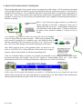
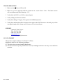
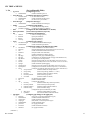
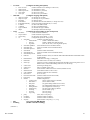
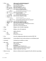
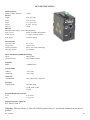
102PC-SE Industrial Serial - Ethernet Protocol Converter User Manual & Installation Guide Rev. 041008 1 Table of Contents APPLICATIONS ................................................................................................................................................3 SAFETY WARNINGS .......................................................................................................................................4 INSTALLATION ...............................................................................................................................................6 FRONT PANEL..................................................................................................................................................8 APPLYING POWER (Top View) ......................................................................................................................9 GROUNDING TECHNIQUES……………………………………………………………………………… 10 RJ45 CONNECTOR CRIMP SPECIFICATIONS……………………………………………………………11 CONNECTING THE UNIT .............................................................................................................................12 SERIAL INTERFACE......................................................................................................................................13 TROUBLESHOOTING ....................................................................................................................................14 FCC STATEMENT ..........................................................................................................................................14 CLI TREE of MENUS ......................................................................................................................................15 SOFTWARE CONFIGURATION ...................................................................................................................19 • Web Management .................................................................................................................................19 • Web Management Tree of Menus.........................................................................................................21 • Ethernet to Serial Connectivity .............................................................................................................27 o Manual Dialout .........................................................................................................................28 o Auto Dialout using Telnet .........................................................................................................29 o Auto Dialout using UDP ...........................................................................................................29 o Remote Bridging with Modem Connection ..............................................................................31 • Serial to Ethernet Connectivity .............................................................................................................31 o Serial Manual Dial-in ................................................................................................................33 o Serial Auto Dial-in Using Telnet ..............................................................................................33 o Serial Auto Dial-in Using UDP ................................................................................................34 o Serial Tunneling Mode .............................................................................................................36 • Using E-mail Features...........................................................................................................................36 o Sending Text E-mails From the Command Prompt ..................................................................37 o Receiving E-mails From the Command Prompt .......................................................................39 KEY SPECIFICATIONS..................................................................................................................................40 N-Tron Limited Warranty .................................................................................................................................40 Rev. 041008 2 Industrial Serial to Ethernet Protocol Converter Installation Guide 102PC-SE The 102PC-SE will IP-enable any serial device to provide remote monitoring, control, and configuration of any serial device. This device is ideal for the following applications: • • • • • • Mounting legacy serial devices to the LAN Industrial and medical remote monitoring systems Data collection Remote diagnostics Remote metering Security systems Rev. 041008 3 Copyright, © N-Tron Corp., 2008 820 S. University Blvd., Suite 4E Mobile, AL 36609 USA All rights reserved. Reproduction, adaptation, or translation without prior written permission from N-Tron Corp. is prohibited, except as allowed under copyright laws. Ethernet is a registered trademark of Xerox Corporation. All other product names, company names, logos or other designations mentioned herein are trademarks of their respective owners. The information contained in this document is subject to change without notice. N-Tron Corp. makes no warranty of any kind with regard to this material, including, but not limited to, the implied warranties of merchantability or fitness for a particular purpose. In no event shall N-Tron Corp. be liable for any incidental, special, indirect, or consequential damages whatsoever included but not limited to lost profits arising out of errors or omissions in this manual or the information contained herein. Warning Do not perform any services on the unit unless qualified to do so. Do not substitute unauthorized parts or make unauthorized modifications to the unit. Do not operate the unit with the top cover removed, as this could create a shock or fire hazard. Do not block the air vents on the sides or the top of the unit. Do not operate the equipment in the presence of flammable gasses or fumes. Operating electrical equipment in such an environment constitutes a definite safety hazard. Do not operate the equipment in a manner not specified by this manual. Safety Warnings GENERAL SAFETY WARNING: If the equipment is used in the manner not specified by N-Tron Corp., the protection provided by the equipment may be impaired. Contact Information N-Tron Corp. 820 South University Blvd. Suite 4E Mobile, AL 36609 TEL: (251) 342-2164 FAX: (251) 342-6353 Website: www.n-tron.com Email: [email protected] Rev. 041008 4 ENVIRONMENTAL SAFETY WARNING: Disconnect the power and allow to cool 5 minutes before touching. ELECTRICAL SAFETY WARNING: Disconnect the power cable before removing the enclosure top. WARNING: Do not operate the unit with the top cover removed. WARNING: Do not work on equipment or cables during periods of lightning activity. WARNING: Do not perform any services on the unit unless qualified to do so. WARNING: Do not block the air vents. WARNING: Observe proper DC Voltage polarity when installing power input cables. Reversing voltage polarity can cause permanent damage to the unit and void the warranty. Rev. 041008 5 Key Features • • • • • • • • • • Serial interface supports speeds up to 115.2Kbps High performance 10/100BaseT Ethernet bridge High performance processor runs ARP, DHCP client, ICMP, IP, PPP, TCP, Telnet, TFTP, HTTP server, SMTP client, POP3 client, and PPP compression Half duplex or full duplex support on the LAN interface 256 frame buffer for Ethernet bridging Stores 10,000 MAC addresses Automatically learns MAC addresses Command line interface The 102PC-SE operates on 10-30VDC Housed in a steel ruggedized DIN rail enclosure, designed to withstand the most demanding industrial applications, and have been fully tested and certified at industrial environmental extremes PACKAGE CONTENTS Please make sure the Serial over Ethernet package contains the following items: 1. 2. 102PC-SE Protocol Converter Product CD Contact your carrier if any items are damaged. Article I. INSTALLATION Read the following warning before beginning the installation: WARNING Never install or work on electrical equipment or cabling during periods of lightning activity. Never connect or disconnect power when hazardous gasses are present. Disconnect the power cable before removing the enclosure top. Do not operate the unit with the top cover removed UNPACKING Remove all the equipment from the packaging, and store the packaging in a safe place. File any damage claims with the carrier. CLEANING Clean only with a damp cloth. Rev. 041008 6 SERVICING Jumper J1 can be changed on the board to change the RJ45 copper port’s MDIX setting. See Connecting the Unit on page 9 for more details. DIN Rail Mounting Install the unit on a standard 35mm DIN rail. Recess the unit to allow at least 5” of horizontal clearance for serial cable bend radius. To install the unit to 35mm industrial DIN rail, place the top edge of the included mounting bracket on the back of the unit against the DIN rail at a 15° angle as shown. Rotate the bottom of the unit to the back (away from you) until it snaps into place. 300-PM 900-PM 900-RM Rev. 041008 To remove the unit from the 35mm industrial DIN rail, place a flat head screwdriver into the orange release clip found at the bottom of the unit, and apply downward force on the clip until it disengages from the bottom of the unit from the DIN rail. Rotate the bottom of the unit towards you and up at an approximate 15° upward angle to completely remove the unit. With the exception of the 524TX and 526FX2, all N-Tron™ products are designed to be mounted on industry standard 35mm DIN rail. However, DIN rail mounting may not be suitable for all applications. We offer three alternative mounting solutions: Our 300 Panel Mount Assembly (P/N: 300-PM) may be used to mount a single 100 or 300 Series unit to a panel or other flat surface. Our 900 Panel Mount Assembly (P/N: 900-PM) may be used to securely mount our 100, 200, 300, 400, 500, or 900 Series products to a panel or other flat surface; Our Rack Mount Assembly (P/N: 900-RM) may be used to mount our products to standard 19" racks. 7 FRONT PANEL From Top to Bottom: Green LED lights when Power is connected RJ45 Ports Auto sensing 10/100 BaseTX Connections Serial RS232 serial port with DCE configuration NOTE: The RJ45 data port has two LED’s located at the left side of the connector. The top LED indicates Activity (ACT), and the lower LED indicates Link (LNK) status. LED’s: The table below describes the operating modes: LED Color Description GREEN Power is Applied OFF Power is OFF GREEN 10/100Mb Link between ports LNK OFF No Link between ports GREEN Data is active between ports ACT OFF Rev. 041008 Data is inactive between ports 8 APPLYING POWER (Top View) Unscrew & Remove the DC Voltage Input Plug from the Power Input Header Install the DC Power Cables into the Plug (observing polarity). Plug the Voltage Input Plug back into the Power Input Header. Tightening torque for the terminal block power plug is 0.22 Nm/0.162 Pound Foot. Verify the Power LED stays ON (GREEN). Note: Only 1 power supply must be connected to power for minimal operation. For redundant power operation, V1 and V2 inputs must be connected to separate DC Voltage sources. This device will draw current from both sources simultaneously. Use 16-28 gauge wire when connecting to the power supply. Recommended 24V DC Power Supplies, similar to: 100VAC/240VAC: N-Tron’s NTPS-24-1.3, DC 24V/1.3A Rev. 041008 9 N-TRON SWITCH GROUNDING TECHNIQUES The grounding philosophy of any control system is an integral part of the design. N-Tron switches are designed to be grounded, but the user has been given the flexibility to float the switch when required. The best noise immunity and emissions (i.e. CE) are obtained when the N-Tron switch chassis is connected to earth ground via a drain wire. Some N-Tron switches have metal din-rail brackets that can ground the switch if the din-rail is grounded. In some cases, N-Tron switches with metal brackets can be supplied with optional plastic brackets if isolation is required. Both V- legs of the power input connector are connected to chassis internally on the PCB. Connecting a drain wire to earth ground from one of the V- terminal plugs as shown here will ground the switch and the chassis. The power leads from the power source should be limited to 3 meters or less in length. As an alternate, users can run a drain wire & lug from any of the Din-Rail screws or empty PEM nuts on the enclosure. When using an unused PEM nut to connect a ground lug via a machine screw, care should be taken to limit the penetration of the outer skin by less than 1/4 in. Failure to do so may cause irreversible damage to the internal components of the switch. Note: Before applying power to the grounded switch, you must use a volt meter to verify there is no voltage difference between the power supply’s negative output terminal and the switch chassis grounding point. If the use of shielded cables is required, it is generally recommended to only connect the shield at one end to prevent ground loops and interfere with low level signals (i.e. thermocouples, RTD, etc.). Cat5e cables manufactured to EIA-568A or 568B specifications are required for use with N-Tron Switches. In the event all Cat5e patch cable distances are small (i.e. All Ethernet devices are located the same local cabinet and/or referenced to the same earth ground), it is permissible to use fully shielded cables terminated to chassis ground at both ends in systems void of low level analog signals. Rev. 041008 10 RJ45 CONNECTOR CRIMP SPECIFICATIONS Please reference the illustration below for your Cat5 cable specifications: Rev. 041008 11 CONNECTING THE UNIT For DCE serial devices (like a modem) use a null modem RS-232 cable to connect to the 102PC-SE. For a DTE serial device (like a computer) use a straight through RS-232 cable. For the 10/100 Base-TX port, plug a Category 5E twisted pair cable into the RJ45 connector. Connect the other end to a PC or a network through a hub or switch. A standard straight through or cross-over Category 5E cable may be used to connect to either device. The MDIX mode of the 102PC-SE can be changed using jumper J1 on the board. By factory default the device is set up to use a straight through cable for a PC. Any N-Tron switch will automatically determine what MDIX the 102PC-SE is using and will connect it to the network. Rev. 041008 12 SERIAL INTERFACE The 102PC-SE provides an EIA-232 interface accessed via a 9 pin male connector (labeled ‘COM’ on the unit). This is used to access the Command Line Interpreter (CLI), and to attach serial devices to the network over Ethernet. The pin-outs are shown below: PIN 1 2 3 4 5 6 7 8 RS-232 DTR TXD RXD DSR & DCD GND DTR CTS RTS Default Port Settings: Baud-Rate: Data Bits: Parity: Stop Bits: Flow Control: 115200 8 None 1 Hardware RTS-CTS Serial Cable Connect the serial COM port of your PC and the 102PC-SE Protocol Converter using a standard straight through cable. You will need a cable with a 9-pin or 25-pin sub-D female connector for the PC end (DTE device), and a 9-pin female sub-D connector for the 102PC-SE end (DCE device). The following table shows the pin-out and the connections for a straight through cable: PC/DTE Device Cable End DTE Device 25-Pin 9-Pin Port Female Female Signal Name Pin # Pin # DCD 8 1 RXD 3 2 TXD 2 3 DTR 20 4 GND 7 5 DSR 6 6 RTS 4 7 CTS 5 8 102 PC-SE Cable End 9-Pin Female Pin # Signal Name 1 DTR 2 TXD 3 RXD 4 DSR & DCD 5 GND 6 DTR 7 CTS 8 RTS Connect the serial COM port of your DCE device and the 102PC-SE Protocol Converter using a null modem cable. You will require a cable with a 9-pin or 25-pin sub-D connector for your DCE device end, and a 9-pin female sub-D connector for the 102PC-SE end. The following table shows the pin-out and the connections for a null modem cable: DCE Device Cable End DCE Device 25-Pin 9-Pin Port Female Female Signal Name Pin # Pin # DTR 8 6+1 TXD 3 2 RXD 2 3 DSR & DCD 20 4 GND 7 5 CTS 4 7 RTS 5 8 Rev. 041008 102 PC-SE Cable End 9-Pin Female Pin # Signal Name 4 DSR & DCD 3 RXD 2 TXD 6+1 DTR 5 GND 8 RTS 7 CTS 13 TROUBLESHOOTING 1. Make sure the (Power LED) is ON. 2. Make sure you are supplying sufficient current for the version chosen. Note: The Inrush current will exceed the steady state current by ~ 2X. 3. Verify that Link LED’s are ON for connected ports. 4. Verify cabling used between stations. 5. Verify that cabling is Category 5E or greater for 100Mbit Operation. 6. Verify that a null-modem cable is being used to connect other DCE devices to the serial port, or that a straight through cable is being used to connect a PC to the serial port. SUPPORT Contact N-Tron Corp. at: TEL: 251-342-2164 FAX: 251-342-6353 www.n-tron.com [email protected] FCC STATEMENT This product complies with Part 15 of the FCC-A Rules. Operation is subject to the following conditions: (1) This device may not cause harmful Interference (2) This device must accept any interference received, including interference that may cause undesired operation. Rev. 041008 14 CLI TREE of MENUS ¾ Set (Set configurable fields) o ag-server o auto-discovery o o o o (enable or disable boot-messages) (Configure bridge modes) enable/disable ipmodule ip-address (enable or disable bridge mode) (Configure the bridge’s ip address) (Configure the date in DD/MM/YYYY format) (Set new device parameters, up to 99) (Configure FTP information) machine filename filesize directory login (remove FTP login options) (specify the filename) (specify the file size) (specify a directory) (Configure login settings) auto-dialout-login enable/disable auto-dialout (enable or disable the auto-dialout feature) def-gway (setup the default gateway in the format of xxx.xxx.xxx.xxx) dns (enable or disable the DNS features below) hostname (setup the 102PC-SE’s hostname) http (enable or disable the webpage options) http-page (display the serial page or the default page) http-port (configure the port number that the web page is broadcasted over) http-banner (set a string to be the http banner) pri-dns (setup the primary DNS server in the format of xxx.xxx.xxx.xxx) sec-dns (setup the secondary DNS server in the format of xxx.xxx.xxx.xxx) syslogd (enable or disable system logging) syslogd-server (setup the server for log files in the format of xxx.xxx.xxx.xxx) tcp-keepalive (configure the time intervals between keep alives, 3-120 minutes) telnet (configure user settings when using telnet to connect to the device) • escape-monitor (enable or disable the escape monitor) • escape-string (set the escape string, default is ‘+++inet’) • inactivity (enable or disable an inactivity timout) • inactivity-timeout (set the inactivity age time) • raw-mode (enable or disable raw mode) telnet-port (set the telnet port number) tftp (enable or disable TFTP) udp (configure udp settings) • inactivity (enable or disable udp’s inactivity feature) • inactivity-timeout (set the inactivity timeout period) • terminate-monitor (enable or disable terminate-monitor) • terminate-string (set the terminate string) eth0 (configuration options for Ethernet port eth0) • dhcp-client (enable or disable DHCP over eth0) • ip-address (set a static IP address and subnet mask) ip (enable or disable auto-dialout-login) (enable or disable login feature) (Configure IP settings for the Ethernet port eth0) o (set the broadcast timer) (enable or disable auto-discovery) (set the server’s port number) (Setup boot messages) enable/disable date device-parameter ftp (enable or disable ag-server) (Configure auto-discovery feature) broadcast-timer enable/disable server-port bridge o o o enable/disable boot-messages (Configure ag-server) ppp ppp0 auth-type authentication compression comp-type enable/disable password raw-mode username (Configure ppp settings for the ppp0 port) (chap, pap, or pap-chap authentication types) (enable or disable authentication) (enable or disable compression) (bsd, deflate, or both compression types) (enable or disable ppp0) (set a ppp0 password) (enable or disable raw-mode) (set a ppp0 username) (continued…) Rev. 041008 15 o recv-mail o send-mail o o o (enable or disable to leave messages on the server) (set the mailbox’s name) (set the mailbox’s password) (set the server’s name) (set the server’s port number) (Configure outgoing mail options) smtp-server-name smtp-server-port host-name from-address from-address-identity to-address cc-address reply-to-address subject serial (Configure incoming mail options) leave-on-server mailbox-name mailbox-password server-name server-port (set the smtp server name) (set the smtp server port number) (set the host name) (set the mail ID for the from address, ex. [email protected]) (string associated with the mail ID, ex. N-Tron) (set the to mail address field) (set the cc mail address field) (set the mail ID reply to address) (set the subject field of the message) (Configure the serial settings for the serial port s0) auto-dialin (enable or disable auto-dialin) escape-monitor (enable or disable escape monitor) escape-string (set the escape string, default ‘+++inet’) s0 (configuration options for serial port s0) • auto-dialin (configure auto dialin settings) o enable/disable (enable or disable auto-dialin) o message (enable or disable auto-dialin message) o trig-mode (char, dtr, dtr-char, or none trig mode options) • auto-dialin-ipaddress (set an IP address for the auto-dialin feature) • auto-dialin-port (set the port number for the auto-dialin feature) • auto-dialin-protocol (telnet) • auto-dialout (enable or disable auto dialout) • auto-dialout-port (set the port number for the auto-dialout feature) • auto-dialout-protocol (telnet) • baud-rate (Possible baud-rate value(s) are 300 600 1200 1800 2400 4800 9600 19200 38400 57600 115200 230400) • buffer-datasize (Buffer data-size range: [1-1500] bytes) • buffer-time (set a buffer time in seconds, 0 for no buffer) • chat-script (Chat-script is used to establish physical link from the dialing to answering end in case of modem connect, when modem dialing-method is set to chat-script.) • connect-state (answering or dialing state) • connect-type (direct or modem connect type) • data-bits (set the number of data-bits over the serial line, default is 8 bits) • dialout-monitor (set the dialout monitor to dtr or none) • echo-command (enable or disable the echo command) • flow-control (rts-cts or none) • host-interaction-mode (enable or disable host interaction mode) • login-string (string up to 8 characters) • modem (modem configuration) o connect-string (set the connect string for a modem) o dial-number (set the number to dial) o dial-prefix (any prefix dialing needed can be set here) o dial-suffix (any suffix dialing needed can be set here) o dialing-method (use configuration of chat-script) o hangup-string (set string used to hang up the line) o init-string (set init number [1-5]) o ok-string (set an ok string) o ring-string (set a ring string) • parity (none, odd, or even parity) • raw-dialin (enable or disable raw-dialin) • raw-dialout (enable or disable raw-dialout) • stop-bits (set the number of stop bits [1, 1.5, or 2]) time watchdog (Set system time HH:MM:SS) (Enable or disable watchdog) (continued…) Rev. 041008 16 ¾ Show o o o o o o o (Show general and detailed information) bridge buildrun configuration date device-parameter ftp configuration ip eth0 o o o o o (shows the configuration of the eth0 port) (shows data statistics of the activity over the eth0 port) (Shows the HTTP configuration settings) (Shows the ppp information) configuration statistics recv-mail config send-mail config serial s0 o o o o o o configuration statistics http configuration ppp (Shows bridging configuration and statistics) (Shows the buildrun settings) (Shows the general configuration) (Shows the date and time) (Show device parameters configured) (Shows the FTP configuration settings) (Shows Ethernet port eth0 information) (shows the configuration for ppp) (shows data statistics of the activity over ppp) (Shows the POP3 configuration settings) (Shows the SMTP configuration settings) chat-script configuration modem-configuration statistics snmp-agent config sntp-client config statistics sys-info time users (shows the chat-script lines) (shows the configuration settings for serial port s0) (shows the modem configuration settings over the serial port s0) (shows the data statistics of the activity over the serial port s0) (Shows the SNMP configuration settings) (Shows the SNTP configuration settings) (Shows the general statistics of the 102PC-SE) (Shows general system information including the MAC address) (Shows the system date and time) (Shows the users setup for the 102PC-SE) ¾ Help (Displays a list of available commands) ¾ Usage (Displays a list of all commands) ¾ User o o o (Add or edit users) add delete password (Add a user) (Delete a user) (Set the password for a user) ¾ Save (Saves the configurations made and restarts the 102PC-SE) ¾ Dialout serial s0 (Used to dialout or look out the serial port over the Ethernet port) ¾ Send-mail (Sends mail, not available over telnet) ¾ Recv-mail o o o o o o o delete header list mail stat top unique-id-listing ¾ Restore session (Received mail options) (delete messages) (view message header) (list messages) (downloads messages from POP3 server) (displays the number of e-mails and total e-mail size) (displays the header and the top part of a message) (displays a unique ID for each message) (Restores a dialout session if you paused it earlier with the escape-string) (continued…) Rev. 041008 17 ¾ Socket o o o o o o o o o o o o (Actions to take over a UDP socket) close (closes a socket by its handle <socket_handle>) closeall (closes all the sockets) flush (flush out a socket by its handle <socket_handle>) flushall (flush out all the sockets) listall (lists all the sockets (TCP connect, TCP listen, and UDP sockets)) listlisten (lists all the TCP listen sockets) recv [-s <max_size>] <socket_handle> (receive over a socket) send < [-s <size>] [-d <delimiter>] > [-m <MTU>] <socket_handle> (send over a socket) stat [-s] [-d] <socket_handle> (lists stats for sockets, -s: socket only, -d: socket detail) tcp <remote_ip> <remote_port> (set up the tcp socket information) tcplisten <local_port> [backlog] (listen on a TCP socket) udp <remote_ip> <remote_port> [local_port] (for UDP server set remote_ip to 0.0.0.0) note: local_port is required for UDP server ¾ Telnet (Allows telnet sessions from the hyper terminal over the serial port) ¾ Ftp (Allows FTP sessions from the hyper terminal over the serial port) ¾ Exit (Logs the user off the telnet or hyper terminal session) ¾ Restore default-config (Sets all config settings back to the default configuration file) Rev. 041008 18 Software Configuration Web Management The 102PC-SE offers users the ability to remotely logon and configure the 102PC-SE through a web browser. Note: By default the 102PC-SE has an IP address of 192.168.1.202 with a subnet mask of 255.255.255.0. If the 102PCSE sees a DHCP server on the network he will use that and acquire the next available IP address that the DHCP server has in its DHCP pool. You must know what the IP address is before you can configure the 102PC-SE through a web browser. If you need to you can configure a static IP address through the serial port. Once an IP address has been configured for the unit it can be remotely configured through a web browser. To configure it over a web browser simply enter the IP address in the web address line of the web browser. You should be prompted to enter a user name and password. You can configure multiple user accounts. Default Settings: User Name: Password: admin admin Once logged in you will be confronted with the following page. Simply click on either link by default they both end up loading to the same page. Note: The Host Configuration page is available to give the user a place to customize the web management features for the serial device that they attach to the 102PC-SE. By default this page is simply forwarded to the IPModule Configuration page. N-Tron does NOT provide software development support for users who wish to customize the Host Configuration page. Rev. 041008 19 Both links should display the page below. Here you can configure every option that the 102PC-SE will support. Note: If you can’t find an option that you are looking to configure you may manually enter the command in through the web browser under the command link at the top of the page. Don’t forget to save the running configuration after making changes. Otherwise settings may not change after a power cycle on the switch. Rev. 041008 20 Web Management Tree of Menus General Configuration • Authentication: Enables/Disables Authentication (Login Prompt) for command line configuration/management via Serial and Ethernet • • • Default: enable BootMessage: Enables/Disables the display of boot-messages during module boot-up Default: enable Autodialout: Enables/Disables Telnet Auto-Dialout authentication Default: enable Watch Dog: Enables/Disables the watchdog timer (6.5 seconds by default) Default: enable User Configuration • Provides to add/delete/modify username and password to the group Notes: o o o Default Groups: admin, users Default Users: admin, ipmodule Only Admin can configure the SocketEthernet IP Port Configuration • Baud Rate :Sets the serial Baud Rate • • • • • • • • • • • • • • Default: 115200 Buffer Size: Sets data buffer size to be sent from serial-to-ethernet. Default: 0 Buffer Time: Sets the buffer time (t deci-secs) to wait before sending from serial-to-ethernet. If t=0, buffer-size=0 no delay. If t=0, buffer-size!=0 buffered till the buffer-size. If t!=0, buffer-size=0, no delay. If t!=0, buffer-size!=0 buffered till the buffer-size or Wait till t deci-sec whichever occurs first. Default: 0 deci-seconds Flow Control: Sets the Flow Control of the serial port Default value: rts-cts Parity: Sets the serial Parity Default value: none Data Bits: Sets the serial Data bits Default value: 8 Stop Bits: Sets the serial Stop bits Default value: 1 Escaes.multiTech.socketProduct.seipInfo.seipIPSetup.seipIPServiceSetup.seipe Monitor: Enables/Disables ‘‘monitor’’ flag to scan escape sequence and switch to command mode during Manual dialin (telnet) session Default: enable Escape String: Sets the escape string to be scanned during Manual Dialin session to switch to command mode Default: +++inet Connect Type: Sets the connect type of the serial port to Direct/Modem Default: Direct Connect State: Sets the connect state of the serial port to dialing/answering Default: Dialing Trig Mode: Sets the trigger mode on the serial port. This mode controls starting/stopping of the Serial Configuration session and Auto-Dialin Session Modes Description o char Initiate a session (Configuration/Telnet/Udp), only on a reception of a character on the serial port s0 o dtr Initiate a session (Configuration/Telnet/Udp), only on seeing a DTR signal on the serial port s0 o dtr-char Initiate a session (Configuration/Telnet/Udp), either on reception of a character (OR) seeing the DTR signal on the serial port s0 o none Initiate a session (Configuration/Telnet/Udp), on module boot-up Default: dtr-char Login String: Sets the login string. When the trig mode is set to char/dtr-char and DTR is down, the session is initiated only if the configured login string is entered Default: NULL Echo Command: Enables/Disables the command echoing on the serial port Default: enable Telnet messages: Enables/Disables the Telnet Client (Manual and Auto-Dialin) connect messages on the serial port Default: disable (continued…) Rev. 041008 21 • Dialout monitor: Sets the dialout monitor to dtr/none Description o dtr Dialout session is terminated when DTR signal on the serial port s0 toggles from High to Low o none Dialout session is not dependant on the DTR signal Default: none Modem Configuration • Connect String: Sets the Modem Connect string • • • • • • • • Default: CONNECT OK String: Sets the Modem OK string Default: OK Hangup String: Sets the Modem hang-up string Default: +++ATH0 Ring String: Sets the Modem Ring string Default: RING Dial Prefix: Sets the Modem Dial-Prefix Default: ATDT Dial Suffix: Sets the Modem Dial-suffix Default: ^M Dial Number: Sets the dial-number to be dialed Default: NULL Dialing method: Sets the modem dialing method Description o Configuration method: User shall provide only the dial-number to reach o Chat-script method: User can write his/her own script by providing an "Expect" and a "Send" sequence Refer to: chat-script for providing an "Expect" and a "Send" sequence Default: configuration Init String: Configure the Modem init strings Init-num can range from 1-5 Chatscript • Sets/Clears expect and send strings for the chat script to act on the modem Bridge Configuration • Bridge: Enables/disables remote transparent bridging between ethernet and serial interface. Enabling bridge will automatically enable telnet, tftp services on • • the module. Disabling will automatically disable PPP on the module Default: disable IP Address: Sets Bridge IP address. Can be set only when Bridge is enabled Default: Ethernet ip address IP Mask: IP mask of the configured IP address PPP Configuration • PPP :Enableis/Disables PPP on the serial port s0. PPP can be enabled only if bridge is enabled • • • • • • • Default: disable Compression:Enables/Disables CCP compression for PPP Default: disable Compression Type: Sets the compression type to bsd, deflate or both o PPP in non raw-mode: When "both" is configured as the compression type, the module tries to negotiate deflate first. In the event of failure, the bsd is negotiated o PPP in raw-mode: Compression type "both" is not supported in raw-mode, since there is no negotiations between SocketEthernet IP Modules Default: deflate Raw Mode: Enables/Disables simple AHDLC framing on the Serial side. In Raw mode, no PPP negotiations are done on the serial. The ethernet data is encapsulated with 7E delimiters. FCS is part of the AHDLC frame header Default: disable Authentication: Enables/Disables PPP authentication Default: disable Authentication Type: Sets the authentication protocol type to negotiate with the remote peer: pap/chap/pap-chap Default: pap Username: PPP username with which remote peer will authenticate Default: ipmodule Password: PPP password with which remote peer will authenticate Default: ipmodule (continued…) Rev. 041008 22 IPGeneral • Hostname: Sets the hostname for the module • • • • • • • • • • • • • • Default: SocketEthernetIP Default Gateway: Sets the IP default gateway address Default: 0.0.0.0 IP DNS: Enables/Disables DNS client on the module Default: disable Pri DNS: Sets the Primary DNS IP address Default: 0.0.0.0 Sec DNS: Sets the Secondary DNS IP address Default: 0.0.0.0 DHCP Client: Enables/Disables DHCP Client Note: o DHCP info parameters DHCP netmask, Gateway, DNS and DHCP server will be set if the module obtains IP address from DHCP server successfully. These cannot be modified. o If DHCP Client fails to contact the DHCP Server, after a finite number of retries, initializes the eth0 with static ip address. It checks periodically and retries to obtain an IP address from a DHCP server Default: enable IP Address: If DHCP is disabled, sets the static IP address of the module. If DHCP is enabled, the ip address given by the DHCP server is displayed and its not configurable. Note: o When the static ip address is modified, the browser gets redirected to new ip address. Default: 192.168.2.1 TFTP: Enables/Disables TFTP Server. On enabling the TFTP Server, the network administrator can upload the firmware to the flash Notes: TFTP application is associated with "inetd" application Configuration change of TFTP service calls for a re-initialization of "inetd", eventually closes all the current session that are associated with "inetd" The other application(s) that are associated with "inetd" are Telnet Server Hence when enabling/disabling TFTP through a Telnet configuration, would terminate the current telnet sessions Default: enable TCP Keepalive: Sets the tcp keepalive timeout (minutes) value. This is used to terminate the TCP session if there is no traffic Default: 3 minutes Autodiscovery: Enables/Disables Auto-discovery to broadcast (MAC Level), the MAC-address, IP address and DHCP information to server port configured (default 1020) Default: enable Server Port: Sets the Auto Discovery Manager Server port Default: 1020 Broadcast Timer: Auto-discovery packet granularity of periodic Broadcasting Default: 10 seconds AG Server: Starts the UDP server on port 526. Starts a Tcp server on port 599. Uses proprietary Multitech Asynchronous Gateway Protocol (AG). o Discovery mechanism - UDP server responds with UDP unicast packet to the UDP broadcast packet from WinMCSI Port Redirector o Status mechanism - TCP server responds to the Status Request packet from the WinMCSI Port Redirector Client Default: disable Auto Dialout: Enables/Disables Auto-Dialout feature globally on the module Default: enable Auto Dialin: Enables/Disables Auto-Dialin feature globally on the module Default: disable Telnet Configuration • Telnet: Enables/Disables the Telnet Server used for Command Line Configuration. On disabling Telnet server, the administrator cannot configure the IP • • • Module through Telnet. The only option is to connect through a terminal application over the Serial port Default: enable Telnet Port: Sets the telnet port used for Command Line Configuration Notes: Telnet application is associated with "inetd" application Modification to the telnet port calls for a re-initialization of "inetd". This inturn closes all the current session that are associated with "inetd" The other application(s) that are associated with "inetd" are TFTP Server. Hence, invoking this command would terminate the current telnet sessions Default: 23 Escape Monitor: Enables/Disables ‘‘monitor’’ flag to scan escape sequence and switch to command mode during Manual dialout session Default: enable Escape String: Sets the escape string to be scanned during Manual Dialout session to switch to command mode Default: +++inet (continued…) Rev. 041008 23 • • • Inactivity: Enables/Disables the inactivity timeout feature. If this is enabled, the telnet/tcp session is terminated if there is no traffic for the configured timeout value Default: disable Inactivity Timeout: Sets the timeout (t seconds) value for the telnet session to be terminated if there is no traffic Default: 300 seconds Raw Mode: Enables/Disables the raw mode for Telnet Auto-Dialout and Serial Auto-Dialin features globally Default: disable UDP Configuration • Terminate Monitor: Sets "monitor" flag which enables/disables the scanning of terminate sequence by the UDP server • • • Default: enable Terminate String: Sets the terminate sequence to be scanned and terminates udp auto-dialout session Default: +++inet Inactivity: Enables/disables inactivity timeout feature Default: disable Inactivity Timeout: Sets the timeout(t seconds) value for the telnet session to be terminated if there is no traffic Default: 300 seconds Autodial Configuration • Autodialin Configuration o Autodialin: Enables/Disables the Serial Auto-Dialin feature for the serial port S0. Auto-Dialin feature on this port is enabled only if global Auto- • Dialin is enabled Default: disable o Autodialin Port: Sets the Serial Auto-Dialin port number to which the session should be establised Default: 23 o IP Address: Sets the Serial Auto-Dialin IP address Default: 127.0.0.1 o Protocol: Sets the protocol to be used by Serial Auto-Dialin feature. Telnet and Udp protocols are supported Default: telnet o Raw Dialin: Enables/Disables raw mode for Serial Auto-Dialin session on the serial port s0. The session will be in Raw mode only if the global raw mode is enabled Default: disable Autodialout Configuration o Autodialout: Enables/Disables the Auto-Dialout feature for the serial port S0. Auto-Dialout feature on this port is enabled only if global AutoDialout is enabled Default: enable o Autodiaout Port: Sets the Serial Auto-Dialout IP address Default: 5000 o Protocol: Sets the protocol to be used by Auto-Dialout feature. Telnet or/and Udp protocols can be used Default: telnet o Host Interaction Mode: Enables/Disables the host interactive mode for HTTP server. When this mode is enabled, the host/serial device can use HTTP server Note: Telnet Auto-Dialout and PPP cannot be enabled when this mode is enabled. Default: disable o Raw Dialout: Enables/Disables raw mode for Auto-Dialout session on the serial port s0. The session will be in Raw mode only if the global raw mode is enabled Default: disable FTP Configuration • Sets/Clears the remote machine, login name, password and account password details which will be used by FTP for automatic authentication • Password is an optional parameter and can be configured along with machine and login names only • Account Password is an optional parameter and can be configured along with machine login name and password only IP Module prompts for login name and • • • password if these details are NULL File Name: Sets the filename to be used for ftp file transfer Filesize: Sets the data size to be sent to the server Directory: Sets the directory path used by transmit and list commands Default for all the above: NULL (continued…) Rev. 041008 24 HTTP Configuration • HTTP: Enables/Disables the HTTP server for the module/host device configuration/monitoring Default: disable HTTP Port: Sets the HTTP server port to listen for requests Default: 80 • HTTP Page: Sets the HTTP server to give control on module configuration from the browser or give access to only serial device pages. If set to "default", the default HTML page (index.html) is launched. If set to "serial", the serial device page (http-s0.html) is launched Default: default Note: The above parameters cannot be changed through browser • HTTP Banner: Sets the banner to be displayed on the HTML pages Default: SocketEthernetIP Module • SNMP Configuration • SNMP-Agent: Enables/Disables the SNMPv1 Agent on the module. SNMP manager compiled with proprietary MIB can configure/monitor the module • • using set/get/getnext commands Default: disable SNMP Port: Sets the SNMP Agent port Default: 161 Community String: Sets the community string so as to respond only to a particular community of managers. The managers indicate to which community they belong in the request message. Default: public SMTP General • Server Name: Sets the SMTP Server name or IP address • • • • • Default: 127.0.0.1 Server Port: Sets the SMTP Server port Default: 25 Host Name: Sets the SMTP Client Host Name Default: NULL From Identity: Sets the ‘From:’ description in the email header Default: NULL From Address: Sets the default From email address Default: NULL Reply-to Address: Sets the default email address to be used when the recipient uses the reply-to button Default: NULL SMTP Address Configuration • To Address: Sets the email addresses as primary addresses. These are the default email addresses to which emails are to be sent. Supports configuration • upto 5 addresses. If these are NULL, send-mail command prompts for the to-address Default: NULL CC Address: Sets the email addresses as alternate addresses (carbon copy). These are the default email addresses to which messages are to be sent other than the primary addresses. Supports configuration upto 5 addressesi. If these are NULL, send-mail command prompts for the cc-address Default: NULL POP3 Configuration • Server Name: Sets the POP3 Server name or IP address • • • • Default: 127.0.0.1 Server Port: Sets the POP3 Server port Default: 110 Mailbox Name: Sets the mail box user name for POP3 server authentication Default: NULL Mailbox Password: Sets the mail box password for POP3 server authentication Default: NULL Leave On Server: Enables/Disables "leave a copy of message on server" flag, which tells the POP3 server not to delete the mails from it once the mails are received Default: disable (continued…) Rev. 041008 25 SNTP General • SNTP Client: Enables/Disables the SNTP Client to contact the configured server on UDP port 123 and set the local time • • • • • • Default: disable Server Name: Sets the NTP server name or IP address to which the SNTP Client has to contact to update the time Default: 127.0.0.1 Time Zone: Sets the time zone Default: UTC Time Zone offset: Sets the offset time from UTC Default: +00:00 (+/-hh:mm) Polling Time: Sets the polling time at which SNTP client requests the server to update the time Default: 300 minutes Daylight Saving: Enables/Disables the Day Light Saving Mode Default: enable Daylight Saving offset: Sets the offset to use during the Day Light Saving Mode Default: +60 (+/-mm) SNTP Daylight Saving Configuration • Start Ordinal: Sets the start ordinal to use during the Day Light Saving Mode. Options - first/second/third/forth/last • • • • • • • Default: first End Ordinal: Sets the last ordinal to use during the Day Light Saving Mode. Options - first/second/third/forth/last Default: last Start Month: Sets the start month to use during the Day Light Saving Mode Default: april End Month: Sets the end month to use during the Day Light Saving Mode Default: october Start Day: Sets the start weekday to use during the Day Light Saving Mode Default: sunday End Day: Sets the end weekday to use during the Day Light Saving Mode Default: sunday Start Time: Sets the start time to use during the Day Light Saving Mode Default: 02:00 (hh:mm) End Time: Sets the end time to use during the Day Light Saving Mode. Default: 02:00 (hh:mm) Commands • User can enter any "set" commands as per the manual View Statistics • Bridge: Displays the Bridge Statistics only when bridge is enabled • eth0: Displays Ethernet Statistics • serial: Displays Serial Statistics • PPP: Displays PPP Statistics only when PPP is enabled • Users: Displays the Default and Added users of the module • System Information: Displays the System information of the module. Processor details, Uptime, Memory utilization, Flash Memory map, Version, Date, Binary details Save • • • Upon clicking Save button, it prompts for confirmation If selected OK, the modified configuration is written into flash and if the box may reboot for few configuration changes. After few seconds, the default.html/http-s0.html page will be launched again as per configuration. If the page is not launched, check the IP address and HTTP configuration status If selected CANCEL, the browser is redirected to General Configuration page Restore Defaults • Upon clicking Restore Defaults button, it prompts for confirmation • If selected OK, the configuration is restored to factory defaults and redirected to General Configuration page. User need to click save button to save the • configuration If selected CANCEL, the browser is redirected to General Configuration page Rev. 041008 26 Ethernet to Serial Connectivity Mandatory Configuration Settings The following items must be configured in order to use the manual dial-out feature: • Disable the Host Interaction Mode to restrict Telnet-Dial-Out and PPP. # set serial <s0> host-interaction-mode disable • Disable Auto dial-out globally on all the serial ports. # set ip auto-dialout disable • Disable Auto dial-out on the serial port s0. # set serial s0 auto-dialout disable The following items must be configured in order to use the auto dial-out feature: • Disable the Host Interaction Mode to restrict Telnet-Dial-Out and PPP. # set serial <s0> host-interaction-mode disable • Enable Auto dial-out globally on all the serial ports. # set ip auto-dialout enable • Enable Auto dial-out on the serial port s0. # set serial s0 auto-dialout enable • Set the Auto dialout port for the serial port s0 . # set serial s0 auto-dialout-port <port_number> • Set the Auto dialout protocol for the serial port s0. # set serial s0 auto-dialout-protocol <telnet or udp>/all An ERROR message will display if any of the above details are not configured or are not valid. Optional Configuration Settings The following details are optional configurations: • Enable/Disable the Authentication for Dial-out session # set login auto-dialout-login <enable/disable> • Enable/Disable the Switching-between-Dialout & CommandPrompt feature # set ip telnet escape-monitor <enable/disable> • Set the Escape-Monitor-String to switch between Dialout and Command Prompt sessions. # set ip telnet escape-string "+++inet" • Enable/Disable the Terminating Dialout Session using Terminate string # set ip udp terminate-monitor <enable/disable> • Set the Terminate-Monitor-String to Terminate the Dialout Session. # set ip udp terminate-string "+++inet" • Enable/Disable the Terminating Dialout Session using Inactivity Timeout # set ip udp inactivity <enable/disable> • Set the Inactivity Timeout to Terminate the Dialout Session. # set ip udp inactivity-timeout 300 • Enable/Disable the Raw mode globally for all Dial-out sessions. # set ip telnet raw-mode <enable/disable> • Enable/Disable the Raw mode for the serial port s0. # set serial s0 raw-dialout <enable/disable> • Set the Baud rate for the serial port s0 to be taken for a Dialout session. # set serial s0 baud-rate <Baud-rate> • Set the Flow control for the serial port s0 to be taken for a Dialout session. # set serial s0 flow-control <rts-cts/none> • Set the Parity for the serial port s0 to be taken for a Dialout session. # set serial s0 parity <even/odd/none> • Set the Data bits for the serial port s0 to be taken for a Dialout session. # set serial s0 data-bits <7/8> • Set the Stop bits for the serial port s0 to be taken for a Dialout session. # set serial s0 stop-bits <1/1.5/2> Rev. 041008 27 Scenario 1 – Manual Dialout • • Connect to the 102PC-SE using a telnet Client on port 23 (or configuration port). At the command prompt, invoke # dialout serial s0. Once the session is opened successfully, there can be two-way traffic between the telnet client and the serial device. o You can switch from Command Prompt to Dialout session using "restore session" command. o You can switch from Dialout session to Command Prompt using "<escape-monitor-string>" respectively. Manual Dialout Feature through Command Shell Commands to Setup Manual Dial-out with the 102PC-SE # set ip eth0 dhcp-client disable # set ip eth0 ip-address 192.168.2.1 # set serial s0 baud-rate 115200 # set serial s0 data-bits 8 # set serial s0 parity none # set serial s0 stop-bits 1 # set serial s0 flow-control rts-cts # save Once the above configuration is saved in the 102PC-SE, use a telnet client and connect to 192.168.1.202 on port 23. On successful login, at the 102PC-SE command prompt, invoke # dialout serial s0 The serial port now opens for use. Notes: 1. Only one dial-out session can be open at a time. 2. The Dial-out session is closed when the Telnet session is closed, thereby releasing the serial port. 3. When Dial-out session authentication is enabled as specified in Optional commands, the session prompts for user-name and password before opening the session successfully. (Enabled by default). 4. The serial port is opened with the current serial configuration. 5. When escape-monitor is enabled, care should be taken during file transfer that the escapemonitor-string is not part of the data. 6. Manual dial-out is supported for the Telnet protocol ONLY and not for the UDP protocol. Rev. 041008 28 Scenario 2 – Auto Dialout Using Telnet In this scenario, the Auto Dial-out session in Telnet mode is opened using a Telnet client. Prerequisites Raw mode (global and each port) must be either enabled or disabled using above-mentioned optional commands. • Auto Dial-out session can be opened by a Telnet client by specifying the configured auto-dialout port. • Once the session is opened successfully, there can be two-way traffic between the telnet session and the remote serial device. Auto Dialout Feature in Telnet Mode Commands to Setup Auto Dialout in Telnet Mode with the 102PC-SE # set ip eth0 dhcp-client disable # set ip eth0 ip-address 192.168.2.1 # set ip auto-dialout enable # set serial s0 auto-dialout enable # set serial s0 auto-dialout-port 5000 # set serial s0 auto-dialout-protocol telnet # set serial s0 baud-rate 115200 # set serial s0 data-bits 8 # set serial s0 parity none # set serial s0 stop-bits 1 # set serial s0 flow-control rts-cts # save Once the above configuration is saved in the 102PC-SE, use a telnet client and connect to 192.168.1.202 on port 5000. This eventually establishes a telnet Auto dial-out session between the 102PC-SE and the serial device. Closing the Telnet client, closes the serial port in use. Notes: 1. Only one dialout session to the same port can be opened at one time. 2. When dialout session authentication is enabled as specified in Optional commands, the session prompts for user-name and password before opening the session successfully. (Enabled by default) 3. The serial port is opened with the current serial configuration. 4. Example above shows RAW Mode disabled. If you plan on using RAW Mode you must enable it in three places (globally, and for each port) Rev. 041008 29 Scenario 3 – Auto Dialout Using UDP In this scenario, the Auto Dial-out session in UDP mode is initiated by an external UDP Client. . Auto Dialout Feature using UDP Mode Commands to Setup UDP Dial-out in the 102PC-SE # set ip eth0 dhcp-client disable # set ip eth0 ip-address 192.168.2.1 # set ip auto-dialout enable # set serial s0 auto-dialout enable # set serial s0 auto-dialout-port 5000 # set serial s0 auto-dialout-protocol udp/all # set serial s0 baud-rate 115200 # set serial s0 data-bits 8 # set serial s0 parity none # set serial s0 stop-bits 1 # set serial s0 flow-control rts-cts # set serial s0 dialout-monitor dtr # set ip udp inactivity enable/disable # set ip udp inactivity-timeout t # set ip udp terminate-monitor enable/disable # set ip udp terminate-string <string> # save Functionality When any UDP client connects to the 102PC-SE on the configured port, the 102PC-SE locks the serial port for that UDP-Client and latches to the UDP client address connected. The UDP-Client is now ready to send or receive data to or from the serial device. How to Terminate the UDP-Dialout Session 1. If the “inactivity” is enabled and the timeout value is configured, the active UDP session will be terminated on the expiry of inactive timeout. 2. If the “terminate-monitor” is enabled, the UDP-Client can terminate the session by sending the terminate-string configured in the 102PC-SE. 3. If both “inactivity” and “terminate-monitor” are enabled, the UDP dialout session is terminated on any of the above two events that occurs first. 4. When the “dialout-monitor” is set to dtr, toggling the DTR signal state terminates The UDP-dialout session. Notes • Authentication is NOT supported for the UDP Dialout feature. • At any given point of time, only one “UDP Client” can send or receive data from the serial-device through the 102PC-SE. • # set serial s0 raw-mode <enable/disable> is NOT applicable for the UDP Auto-dialout feature. Rev. 041008 30 Scenario 4 – Remote Bridging with Modem Connection This example of remote transparent bridging uses a modem connection between the serial ports. Transparent Bridging with Modem Connection Commands Setup for Segment-1 # set ip eth0 dhcp-client disable # set ip eth0 ip 192.168.2.1 # set bridge enable # set bridge ipmodule ip-address 192.168.2.1 # set ppp ppp0 enable # set ppp ppp0 raw-mode enable [Only if simple AHDLC quoting on the serial port is required.] Commands Setup for Segment-2 # set ip eth0 dhcp-client disable # set ip eth0 ip 192.168.2.10 # set bridge enable # set bridge ipmodule ip-address 192.168.2.10 # set ppp ppp0 enable # set ppp ppp0 raw-mode enable # set serial s0 connect-type modem [Only if simple AHDLC quoting on the serial port is required.] # set serial s0 connect-state dialing # set serial s0 connect-type modem # set serial s0 modem init-string 1 "+++ATH0" # set serial s0 connect-state answering # set serial s0 modem init-string 2 "AT&F" # set serial s0 modem init-string 1 "+++ATH0" # set serial s0 modem dial-number 234 # set serial s0 modem init-string 2 "AT&F" # set serial s0 baud-rate 115200 # set serial s0 baud-rate 115200 # set serial s0 data-bits 8 # set serial s0 data-bits 8 # set serial s0 parity none # set serial s0 parity none # set serial s0 stop-bits 1 # set serial s0 stop-bits 1 # save Notes: 1. For simple AHDLC quoting on the serial port, the raw-mode has to be enabled on both the 102PC-SEs. Raw-mode is disabled by default 2. 102PC-SE Module-1 is configured for modem dialing. 102PC-SE Module-2 is configured for modem answering. 3. If you wish to have a complete control on the modem-dialing end, use the chat-scripts. By default the dialing-method is configuration. 4. Refer the following commands in the Command Line Section for more details on the chatscripts. # set serial s0 modem dialing-method ? # set serial s0 chat-script ? Important Note: The chat-script should be used ONLY FOR THE DIALING END. Rev. 041008 31 Serial to Ethernet Connectivity Mandatory Configuration Settings The following items must be configured in order to use the manual dial-in feature: • Disable Auto dial-in globally on all the serial ports. # set serial auto-dialin disable • Disable Auto dial-in on the serial port s0. # set serial s0 auto-dial-in disable The following items must be configured in order to use the auto dial-in feature: • Enable Auto dial-in globally on all the serial ports. # set serial auto-dialin enable • Enable Auto dial-in on the serial port s0. # set serial s0 auto-dial-in enable • Set the Auto dial-in protocol. # set serial s0 auto-dialin-protocol <telnet or udp> • Set the Auto dial-in Server IP Address. # set serial s0 auto-dialin-ipaddress <ipaddress> • Set the port to the one which the telnet client will be connected. # set serial s0 auto-port-port <port_number> An ERROR message will display if any of the above details are not configured or not valid. Optional Configuration Settings The following details are optional configurations: • Enable/Disable Switching-between-Dial-in and the Command Prompt feature. # set serial escape-monitor <enable/disable> • Set the Escape-Monitor-String to switch between Dial-in and Command Prompt sessions. # set serial escape-string "+++inet" • Set the Serial Dial-in Trigger mode. Dictates the criterion for establishing a connection. The options provided are on reception of <char/ dtr/ dtr-char/ none>. Refer the command line configuration section for a detail know how of this command. # set serial s0 auto-dialin trig-mode <char/dtr/dtr-char/none> • Enable/Disable the Raw mode globally for all Auto-Dial-in sessions. # set ip telnet raw-mode <enable/disable> • Enable/Disable the Raw mode for Auto-Dial-in session on serial port s0. # set serial s0 raw-dial-in <enable/disable> Rev. 041008 32 Scenario 1 – Manual Serial Dial-in Login in to the Command prompt from the serial side. Invoke # telnet <ip-address> <port> at the command prompt. Once the session is opened successfully, there can be two-way traffic between the serial device and the remote server. • You can switch from Command Prompt to Dial-in session using restore session command. • You can switch from Dial-in session to Command Prompt using <escape-monitor-string>. Manual Dial-in Feature Through the Command Shell Commands to Setup Manual Dial-In with the 102PC-SE # set ip eth0 dhcp-client disable # set ip eth0 ip-address 192.168.2.1 # set serial s0 baud-rate 115200 # set serial s0 data-bits 8 # set serial s0 parity none # set serial s0 stop-bits 1 # set serial s0 flow-control rts-cts # save Once the above configuration is saved on the 102PC-SE, login to the 102PC-SE through the serial port. At the command shell invoke: # telnet 192.168.2.10 23 The telnet client on board in the 102PC-SE establishes a virtual serial tunnel between the serial device and the Telnet Server. Notes: 1. You can not open more than one dial-in session. 2. The dial-in session is closed when the telnet session is closed. 3. When escape-monitor is enabled, care should be taken during file transfer that the escapemonitorring is not part of the data. 4. The manual dial-in is supported for Telnet ONLY and not for UDP. Rev. 041008 33 Scenario 2 – Serial Auto Dial-in Using Telnet This example shows how to setup a serial auto dial-in session in telnet mode. The auto dial-in session is opened by telnet client in the 102PC-SE to the configured server on a configured port. Once the session is opened, there can be two-way traffic between the serial device and the remote server. • You can switch from Command Prompt to Dial-in session using the restore session command. • You can switch from Dial-in session to Command Prompt using <escape-monitor-string>. Prerequisites Raw mode (global and each port) must be either enabled or disabled using above-mentioned optional commands Auto Dial-in Feature in Telnet Mode Commands to Setup Auto Dial-In in Telnet Mode with the 102PC-SE # set ip eth0 dhcp-client disable # set ip eth0 ip-address 192.168.2.1 # set serial auto-dialin enable # set serial s0 auto-dialin enable # set serial s0 auto-dialin trig-mode dtr-char # set serial s0 auto-dialin-ipaddress 192.168.2.10 # set serial s0 auto-dialin-port 23 # set serial s0 auto-dialin-protocol telnet # set serial s0 baud-rate 115200 # set serial s0 data-bits 8 # set serial s0 parity none # set serial s0 stop-bits 1 # set serial s0 flow-control rts-cts # save When detecting either a DTR signal (or) any character received from the serial device connected to the serial port of 102PC-SE, the Telnet client in the 102PC-SE establishes a telnet session to 192.168.2.10 on port 23. The serial tunnel between the serial device and the Telnet Server terminates in one of the following conditions. • A physical disconnection of the serial device from the serial port of the 102PC-SE. • The Telnet Client on board is terminated. • The Telnet Server terminates the session. Notes: 1. You can not open more than one Dial-in session. 2. The Dial-in session is closed when the configuration session is closed (if opened). 3. When escape-monitor is enabled, care should be taken during file transfer that the escapemonitorstring is not part of the data. 4. Example above shows RAW Mode disabled. If you plan on using RAW Mode you must enable it in three places (globally, and for each port) Rev. 041008 34 Scenario 3 – Serial Auto Dial-in Using UDP This example shows how to setup a serial auto dial-in session in UDP mode. The auto dial-in session is opened by the UDP client in the 102PC-SE to the configured server on a configured port. Once the session is opened, there can be two-way traffic between the serial device and the remote server. • You can switch from Command Prompt to Dial-in session using the restore session command. • You can switch from Dial-in session to Command Prompt using <escape-monitor-string>. Auto Dial-in Feature in UDP Mode Commands to Setup Auto Dial-In in Telnet Mode with the 102PC-SE # set ip eth0 dhcp-client disable # set ip eth0 ip-address 192.168.2.1 # set serial auto-dialin enable # set serial s0 auto-dialin enable # set serial s0 auto-dialin trig-mode dtr-char # set serial s0 auto-dialin-ipaddress 192.168.2.10 # set serial s0 auto-dialin-port 23 # set serial s0 auto-dialin-protocol udp # set serial s0 baud-rate 115200 # set serial s0 data-bits 8 # set serial s0 parity none # set serial s0 stop-bits 1 # set serial s0 flow-control rts-cts # save Functionality After booting, the SocketEthernet IP Module initiates a UDP Auto-dialin session to the configured server, depending on the configured Auto-dialin trig mode settings. 1. dtr: Upon detecting DTR on the serial port S0, it initiates the UDP session. 2. char: Upon entering any character, it initiates the session. (Login string is associated with this mode, so we need to enter the login string if it is not NULL to initiate the session). 3. dtr-char: Either of the above cases. 4. none: No dependency, the module initiates the session as soon as it boots up. Notes: 1. More than one Dial-in session cannot be opened at a time. 2. No Authentication support. 3. When, escape-monitor is enabled, care should be taken during data transfer for Escape string occurrence in the data. 4. Raw mode is not applicable. Rev. 041008 35 Scenario 4 – Serial Tunneling Mode This scenario shows a serial tunnel established between two serial devices (Serial Device-1, Serial Device-2) using two 102PC-SEs, which are geographically located apart. Serial Tunneling Commands for Module-1 (Configure for Serial Auto Dial-in). Commands for Module-2 (Configure for Telnet Auto Dial-out) # set ip eth0 dhcp-client disable # set ip eth0 ip-address 192.168.2.1 # set ip telnet raw-mode enable # set serial auto-dialin enable # set serial s0 raw-dialin enable # set serial s0 auto-dialin enable # set serial s0 auto-dialin trig-mode none # set serial s0 auto-dialin-ipaddress 192.168.2.10 # set serial s0 auto-dialin-port 23 # set serial s0 auto-dialin-protocol telnet # set serial s0 baud-rate 115200 # set serial s0 data-bits 8 # set serial s0 parity none # set serial s0 stop-bits 1 # set serial s0 flow-control rts-cts # save # set ip eth0 dhcp-client disable # set ip eth0 ip-address 192.168.2.10 # set ip auto-dialout enable # set ip telnet raw-mode enable # set serial s0 auto-dialout enable # set serial s0 auto-dialout-port 5000 # set serial s0 auto-dialout-protocol telnet # set serial s0 raw-dialout enable # set serial s0 baud-rate 115200 # set serial s0 data-bits 8 # set serial s0 parity none # set serial s0 stop-bits 1 # set serial s0 flow-control rts-cts # save Rev. 041008 36 Using E-Mail Features Mandatory Configuration Settings The following items must be configured in order to send e-mails: • Set the SMTP server address. # set send-mail smtp-server-name <smtp.servername.com> • Set the port number the SMTP server is using. # set send-mail smtp-server-port <25> • Set the host name that you are sending from. # set send-mail host-name <hostname> • Set the e-mail address that you are sending from. # set send-mail from-address <[email protected]> • Set an identity for this e-mail address that you are sending from. # set send-mail from-address-identity <Smith> The following items must be configured in order to receive e-mails: • Set the POP3 server address. # set recv-mail server-name <mail.servername.com> • Set the port number the POP3 server is using. # set recv-mail server-port <110> • Set the user name for the POP3 server. # set recv-mail mailbox-name <username> • Set the password for the username’s account on the POP3 server. # set recv-mail mailbox-password <password> • Configure if you want to leave the messages on the POP3 server or not. # set recv-mail leave-on-server <enable/disable> Rev. 041008 37 Sending Text E-mails from the Command Prompt Issue the following command: send-mail -t "<email #1>, <email #2>" -c "<email #3>, <email #4>" -s "subject data" -d "Messagebody" send-mail To: <email #1> To: To address not given Cc: Cc address not given Subject: <enter subject here> Message body: Enter Ctrl+D to end mail, Ctrl+C to quit mail _ A message is then given as shown in the figure below and the email is sent only to the to-addresses (if any) and the cc-addresses (if any) entered from the command prompt. The subject and message body are also taken from the command prompt. Login: admin Password: logged in successfully # send-mail -t "[email protected]" -s "test" -d "Testing e-mail Features..." OK: Mail sent # send-mail To: [email protected] To: To address not given Cc: Cc address not given subject: testing Message body: Enter Ctrl+D to end mail, Ctrl+C to quit mail Testing the e-mail features on the 102PC-SE..." ^D OK: Mail sent # Notes: 1. The email is not sent to addresses pre-configured using set commands. 2. At least one address, either the to-address or the cc-address, should be given as an alternative for sending email irectly from command prompt. 3. If the subject option is not specified and is not pre-configured using set commands, SMNP enters into interactive mode and requests a subject to be entered. 4. Type Ctrl+C to quit the email at any given time. Rev. 041008 38 Receiving E-mails from the Command Prompt The command recv-mail mail can be used to retrieve all the emails from a POP3 server. This command will retrieve all the email with headers, message body, and attachments. The command recv-mail mail <n>, where n is the message number, can be used to retrieve the nth message. Login: admin Password: logged in successfully #recv-mail mail Return-Path: <[email protected]> Received: from adsl-220-163-81.mob.bellsouth.net ([68.220.163.81]) by ibm61aec.bellsouth.net (InterMail vG.1.02.00.01 201-2136-104-101-20050929) with SMTP id <20050525195032.PFUE1498.ibm61aec.bellsouth.net@adsl-220-163-81.mob.bellsouth.net> for <[email protected]>; Wed, 25 May 2005 15:50:32 -0400 Reply-To: [email protected] Date: Thu, 01 Jan 1970 00:17:11 +0000 From: "Smith" <[email protected]> To: [email protected] Subject: test MIME-Version: 1.0 Content-Type: text/plain; charset=ISO-8859-1 Content-Transfer-Encoding: 7bit Message-Id: <20050525195032.PFUE1498.ibm61aec.bellsouth.net@adsl-220-163-81.mobbellsouth.net> Testing e-mail features... OK: Message 1 Received Return-Path: <[email protected]> Received: from adsl-220-163-81.mob.bellsouth.net ([68.220.163.81]) by ibm61aec.bellsouth.net (InterMail vG.1.02.00.01 201-2136-104-101-20050929) with SMTP id <20050525195053.PFXI1498.ibm61aec.bellsouth.net@adsl-220-163-81.mob.bellsouth.net> for <[email protected]>; Wed, 25 May 2005 15:50:53 -0400 Reply-To: [email protected] Date: Thu, 01 Jan 1970 00:17:32 +0000 From: "Smith" <[email protected]> To: [email protected] Subject: testing MIME-Version: 1.0 Content-Type: text/plain; charset=ISO-8859-1 Content-Transfer-Encoding: 7bit Message-Id: <20050525195053.PFXI1498.ibm61aec.bellsouth.net@adsl-220-163-81.mob.bellsouth.net> Testing the e-mail features on the 102PC-SE......" OK: Message 2 Received # Notes: 1. You can receive 1 message at a time by specifying which message you want to look at in the <n> field. 2. The body of the message is located at the very end of the message just before “OK: Message n Received”. 3. Type Ctrl+C to quit the email at any given time. Rev. 041008 39 KEY SPECIFICATIONS Switch Properties Number of MAC Addresses 10,000 Physical Height: 3.98" (10.11cm) Width: 2.01" (5.10 cm) Depth: 3.91" (9.931 cm) Weight: 0.75 lbs (0.3 kg) DIN rail: 35mm Electrical Redundant Input Voltage: 10-30 VDC (Regulated) Input Current: 40 mA @ 24VDC (Steady State) Inrush Current: 7.0 Amp / 0.5 ms @ 24VDC Input Ripple: Less than 100 mV Environmental Operating Temp: Storage Temp: Operating Humidity: Operating Altitude: 0°C to 70°C -40°C to 85°C 20% to 95% (Non Condensing) 0 to 10,000 ft. Shock and Vibration (bulkhead mounting) Shock: 200g @ 10ms Vibration/Seismic: 50g, 5-200Hz, Triaxial Reliability MTBF: >2Million Hours Network Media 10BaseT: 100BaseTX: >Cat3 Cable >Cat5 Cable Connectors 10/100BaseTX: One (1) RJ-45 TX Copper Port Serial Port Com Parameters 400, 4800, 9600, 19.2K, 38.4K, 57.6K, 115.2K Recommended Wiring Clearance: Front: 2" (5.08 cm) Top: 3" (7.62 cm) Emissions and Safety Approvals: FCC Part 15 Class A Warranty: Effective January 1, 2008, all N-TRON products carry a 3 year limited warranty from the date of purchase. Rev. 041008 40 N-TRON Limited Warranty N-TRON, Corp. warrants to the end user that this hardware product will be free from defects in workmanship and materials, under normal use and service, for the applicable warranty period from the date of purchase from N-TRON or its authorized reseller. If a product does not operate as warranted during the applicable warranty period, N-TRON shall, at its option and expense, repair the defective product or part, deliver to customer an equivalent product or part to replace the defective item, or refund to customer the purchase price paid for the defective product. All products that are replaced will become the property of N-TRON. Replacement products may be new or reconditioned. Any replaced or repaired product or part has a ninety (90) day warranty or the remainder of the initial warranty period, whichever is longer. N-TRON shall not be responsible for any custom software or firmware, configuration information, or memory data of customer contained in, stored on, or integrated with any products returned to N-TRON pursuant to any warranty. OBTAINING WARRANTY SERVICE: Customer must contact N-TRON within the applicable warranty period to obtain warranty service authorization. Dated proof of purchase from N-TRON or its authorized reseller may be required. Products returned to N-TRON must be pre-authorized by N-TRON with a Return Material Authorization (RMA) number marked on the outside of the package, and sent prepaid and packaged appropriately for safe shipment. Responsibility for loss or damage does not transfer to N-TRON until the returned item is received by N-TRON. The repaired or replaced item will be shipped to the customer, at N-TRON’s expense, not later than thirty (30) days after N-TRON receives the product. N-TRON shall not be responsible for any software, firmware, information, or memory data of customer contained in, stored on, or integrated with any products returned to N-TRON for repair, whether under warranty or not. ADVANCE REPLACEMENT OPTION: Upon registration, this product qualifies for advance replacement. A replacement product will be shipped within three (3) days after verification by N-TRON that the product is considered defective. The shipment of advance replacement products is subject to local legal requirements and may not be available in all locations. When an advance replacement is provided and customer fails to return the original product to N-TRON within fifteen (15) days after shipment of the replacement, NTRON will charge customer for the replacement product, at list price. WARRANTIES EXCLUSIVE: IF AN N-TRON PRODUCT DOES NOT OPERATE AS WARRANTED ABOVE, CUSTOMER'S SOLE REMEDY FOR BREACH OF THAT WARRANTY SHALL BE REPAIR, REPLACEMENT, OR REFUND OF THE PURCHASE PRICE PAID, AT N-TRON'S OPTION. TO THE FULL EXTENT ALLOWED BY LAW, THE FOREGOING WARRANTIES AND REMEDIES ARE EXCLUSIVE AND ARE IN LIEU OF ALL OTHER WARRANTIES, TERMS, OR CONDITIONS, EXPRESS OR IMPLIED, EITHER IN FACT OR BY OPERATION OF LAW, STATUTORY OR OTHERWISE, INCLUDING WARRANTIES, TERMS, OR CONDITIONS OF MERCHANTABILITY, FITNESS FOR A PARTICULAR PURPOSE, SATISFACTORY QUALITY, CORRESPONDENCE WITH DESCRIPTION, AND NON-INFRINGEMENT, ALL OF WHICH ARE EXPRESSLY DISCLAIMED. N-TRON NEITHER ASSUMES NOR AUTHORIZES ANY OTHER PERSON TO ASSUME FOR IT ANY OTHER LIABILITY IN CONNECTION WITH THE SALE, INSTALLATION, MAINTENANCE OR USE OF ITS PRODUCTS. N-TRON SHALL NOT BE LIABLE UNDER THIS WARRANTY IF ITS TESTING AND EXAMINATION DISCLOSE THAT THE ALLEGED DEFECT OR MALFUNCTION IN THE PRODUCT DOES NOT EXIST OR WAS CAUSED BY CUSTOMER'S OR ANY THIRD PERSON'S MISUSE, NEGLECT, IMPROPER INSTALLATION OR TESTING, UNAUTHORIZED ATTEMPTS TO OPEN, REPAIR OR MODIFY THE PRODUCT, OR ANY OTHER CAUSE BEYOND THE RANGE OF THE INTENDED USE, OR BY ACCIDENT, FIRE, LIGHTNING, POWER CUTS OR OUTAGES, OTHER HAZARDS, OR ACTS OF GOD. LIMITATION OF LIABILITY: TO THE FULL EXTENT ALLOWED BY LAW, N-TRON ALSO EXCLUDES FOR ITSELF AND ITS SUPPLIERS ANY LIABILITY, WHETHER BASED IN CONTRACT OR TORT (INCLUDING NEGLIGENCE), FOR INCIDENTAL, CONSEQUENTIAL, INDIRECT, SPECIAL, OR PUNITIVE DAMAGES OF ANY KIND, OR FOR LOSS OF REVENUE OR PROFITS, LOSS OF BUSINESS, LOSS OF INFORMATION OR DATA, OR OTHER FINANCIAL LOSS ARISING OUT OF OR IN CONNECTION WITH THE SALE, INSTALLATION, MAINTENANCE, USE, PERFORMANCE, FAILURE, OR INTERRUPTION OF ITS PRODUCTS, EVEN IF N-TRON OR ITS AUTHORIZED RESELLER HAS BEEN ADVISED OF THE POSSIBILITY OF SUCH DAMAGES, AND LIMITS ITS LIABILITY TO REPAIR, REPLACEMENT, OR REFUND OF THE PURCHASE PRICE PAID, AT N-TRON'S OPTION. THIS DISCLAIMER OF LIABILITY FOR DAMAGES WILL NOT BE AFFECTED IF ANY REMEDY PROVIDED HEREIN SHALL FAIL OF ITS ESSENTIAL PURPOSE. DISCLAIMER: Some countries, states, or provinces do not allow the exclusion or limitation of implied warranties or the limitation of incidental or consequential damages for certain products supplied to consumers, or the limitation of liability for personal injury, so the above limitations and exclusions may be limited in their application to you. When the implied warranties are not allowed to be excluded in their entirety, they will be limited to the duration of the applicable written warranty. This warranty gives you specific legal rights which may vary depending on local law. GOVERNING LAW: This Limited Warranty shall be governed by the laws of the State of Alabama, U.S.A. Rev. 041008 41