1
Godiag M8 User Manual
Godiag M8 Wireless Auto Scanner
User Manual
2012
Introduction
Welcome to use Godiag M8 Instrument
Thank you for using Godiag M8 Automatic Diagnostic Tool (hereinafter called M8 ).
This manual mainly contains customer support, device overview, device registration
method, device connection, device operation method, and device upgrade method, etc.
Therefore, please read this manual carefully before using the instrument so that you can use it in
a quick and correct way. The manual only introduces how to operate and use the instrument.
Please refer to original repair manual for repair and diagnosis of a specific automobile. The
manual is prepared based on the existing functions and configurations of product. Its contents
are subject to change without notice.
Copyright
The Copyright of this Manual will be belonging to Godiag, Any person and company will be
prohibited to copy or release by any form.
Trade Mark
The trade marks referred and other trade marks in the user manual belong to registered
company.
Customer Support
To obtain the assistance with a question or problems during using Godiag scanner, or to
arrange warranty or non-warranty repairs, to contact our customer support center is provided.
2
Before contact us:
Before making a call or Email to our custom support center
1,Your name &address should provided.
2,Serial number of the equipment
3,parts number& quantity of the items to be requested
4,your phone number or email address which our technician may be reached.
Prepare a brief description of the problems ,like
1,When the problems occurred
2,List the errors when display in the laptop
3,Vehicels information( brand,model,year---)
Why using this manual
To increase their effectiveness of Godiag ,familiarize yourself with the format and information
in this manual, so that you can practiced and effectively operate Godiag.
Vehicles system familiarity
Even though M8 is a powerful auto diagnostic tool, but it cannot replace knowledge & skills.
In order to get more better to operate M8 , it is necessary to have a complete understanding
vehicles system.
When using M8to diagnose the vehicles, you’d better also refer service manual and other
similar service bulletins.
3
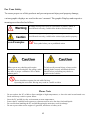
For Your Safety
To ensure proper use of this products and prevent personal injury and property damage,
various graphic displays are used in the user’s manual. The graphic Displays and respective
meanings are described as follows.
Warning message alert your to a procedure or practice which, if
not followed correctly, could lead to death or serious injury.
Caution messages alert you to a procedure or practice which , if
not followed correctly, could lead to serious injury and/or property.
Icon Examples
This symbol alerts you to prohibited action
When operate any checking with engine
running in an enclosed place like garage, make
sure there is proper ventilation. Never inhale
exhaust gases.
To help avoid personal injury, always set the
parking brake securely and block the drive
wheels before performing any checks or
repairs on the vehicles.
Drives should not operate the unit while Driving.
-Operating the unit while Driving may result in a traffic accident.
Please Note
-
Do not explore the PC or M8 to direct sunlight or high temperatures, or leave the unit in sun-heated cars.
Such action may result in system failure
Store the PC and M8 in a dry environment at room temperatures.
Protect the PC and M8 from exposure to elements such as rain, dirt dust, food and liquids.
Be careful when handling the PC and M8.Dropping the units may result in admage.
Do not expose either unit to engine oil, gasoline, antifreeze or battery acid.
4
Tables of Contents
Introduction ..................................................................................................................... 1
Tables of Contents ........................................................................................................... 5
1.Products Overview ....................................................................................................... 7
1.1 Functions ....................................................................................................................................... 7
1.2 Features .......................................................................................................................................... 8
2. Hardware Instruction ................................................................................................... 8
2.1 Hardware Introduction .................................................................................................................. 8
2.2 Hardware Connection Introduction ............................................................................................ 9
2.3 Vehicle Connection......................................................................................................................... 9
2.4 Communication Configration .................................................................................................... 10
2.5 Socket Introduction ...................................................................................................................... 11
3. Operation Condition .................................................................................................. 13
4. Usage Instruction....................................................................................................... 14
4.1 Godiag M8 Software Installation and Configuation ............................................................ 14
4.1.1 Steps of Godiag Software Installation ............................................................................................. 14
4.1.2 Godiag M8 Software Using Instruction .......................................................................................... 23
4.1.3 Ways to Checking the Hardware/ PC Connection is Good ............................................................. 24
4.2 Wireless Communication ............................................................................................................ 26
4.2.1 TCP/IP Setting on Computer Wireless Device ................................................................................ 26
4.2.2 Problems Might be Met When Wifi Setting and the Ways to Solve ............................................... 34
5.Solutions During Installation ..................................................................................... 40
6. Products Update ........................................................................................................ 40
6.1 Software Update .......................................................................................................... 40
6.2 Hardware Update ......................................................................................................... 40
5
7. Maintenance and Service .......................................................................................... 42
7.1 Limit Range of Maintenance Service .......................................................................... 42
7.2 Out of Guarantee Range .............................................................................................. 43
6
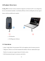
1.Product Overview
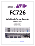
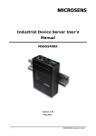
Godiag M8 is the latest wireless automotive diagnostic tool based on PC. It was designed by
the new international standard, it can identify different vehicles intelligently and can support
almost vehicles available in the market.
①
②
① M8 Interface
② M8 Diagnostic Software
1.1 Functions
Adopt
16 digit Dual Cell specialized CPU, Full compliant with all vehicles protocols.
Diagnostic software accord with international standard, collocate communication port
flexibly, less connectors support almost all vehicles socket.
Self-determination design for connectors and cables.
7
1.2 Features
ITEM
CPU
FLASH
Diagnostic Port
Wire Port
Power Supply
Consumption
Weight
Size
Working Temperature
Storage Temperature
Description
16 digit Dual Cell specialized CPU
256KB FALSH
OBD 16 PIN
USB 2.0 or Wifi IEEE 802.11b/g
DC 5V-18V
12W
150g
110mm(L) X 50mm(W) X31mm(W)
-20~+70 °C
-40~+85 °C
2. Hardware Instruction
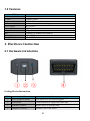
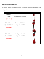
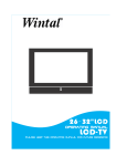
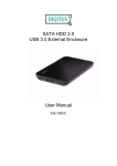
2.1 Hardware Introduction
① ② ③
④
Godiag Device Instruction
ITEM
NAME
Instruction
①
Reset &Upgrade Button
Reset Interface or use software upgrade
②
USB Socket
Connect Interface to Laptop with USB Cable
③
Indicate Led (Red)
Indicate Power or working status
④
Diagnose Connector
Standard CAN 16 Pin Socket
8
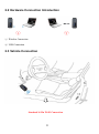
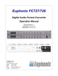
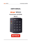
2.2 Hardware Connection Introduction
①
②
① Wireless Connection
② USB Connection
2.3 Vehicle Connection
Standard 16 Pin Wi-Fi Connection
9
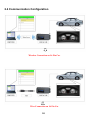
2.4 Communication Configuration
Wireless Connection on 16 Pin Car
Wire Connection on 16 Pin Car
10
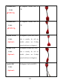
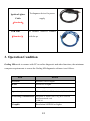
2.5 Socket Introduction
As different vehicles need different sockets, the following sheet is the introduction of the
mating sockets.
Name
Introduction
KIA 20-PIN
Cable
To diagnose KIA with 20PIN
(Standard)
Mitsubishi
/Hyundai 12 Cable
To diagnose Mitsubishi
/Hyundai with 12PIN
(Standard)
Mitsubishi
/Hyundai 16Cable
To diagnose Mitsubishi
/Hyundai with 16PIN
(Standard)
11
Picture
Nissan14-PIN
Cable
To diagnose Nissan with 14
PIN
(Standard)
Nissan16-PIN
Cable
To diagnose Nissan with 16
PIN
(Standard)
Toyota 22-PIN
Cable
(Optional)
To diagnose Toyota with 22PIN
(this is mainly for old car
models, please use Godiag
general software to diagnose)
Honda 3-PIN
Cable
(Optional)
To diagnose Honda with 3PIN
(this is mainly for old car
models, please use Godiag
general software to diagnose)
Audi 4-PIN
To diagnose Audi with 4PIN
Cable
(Optional)
12
Ignition Lighter
To diagnose device for power
Cable
supply
(Standard)
USB Line
To connect A500.G3 scanner
(Standard)
with the pc
3. Operation Condition
Godiag M8 needs to connect with PC to realize diagnostic and other functions, the minimum
computer requirements to execut the Godiag M8 diagnostic software is as follows.
Item
Details
Processor
Pentium3/1GHz or higher
RAM
At least 1G or higher
Hard Disk Drive
160G or higher
Operation system
Microsoft Window XP Professional (Version 2002)
Networking/Communication Integrated or installer 802.11b/g WiFi certified
wireless network card
-USB 2.0
Graphic
Resolution 800X600 or higher
13
4. Usage Instruction
4.1 Godiag M8 Software Installation and Configuration
Note
The Instruction on the software and operation system setting in this manual are applicable on
Microsoft Windows XP professional Only.
4.1.1 Steps of Godiag M8 software Installation
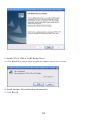
1,Double click 【Godia_Setup_V2.9.exe】 which is contained in the CD-ROM.
2, Choose Setup Language then Click 【OK】
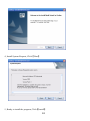
3, On the Welcome page ,Press “Next” button to continue the installation or press “Cancel”
to abort installation.
14
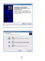
4, Install System Request, Click【Next】
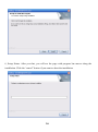
5, Ready to install the program, Click【Install】
15
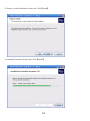
6, Setup Status. After you that, you will see the page with progress bar moves along the
installation. Click the “cancel” button if you want to abort the installation.
16
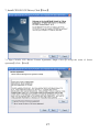
7, Install CP210X VCP Drives, Click【Next】
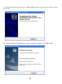
7.1 Sign CP210X VCP Drivers License Agreement, Single Click 【 I accept the terms of license
agreement】,Click 【Next】
17
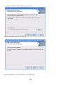
7.2
Choose CP210X VCP Drivers Destination Location
7.3 Ready to Install the CP210x VCP Drives.
7.4 Finish installing of CP210x VCP Drives, Click【Finish】
18
8, Install CP210x USB to UART Bridge Driver
8.1 Click【Install】,if prompted need to restart the computer, choose later to restart.
9, Install Auxiliary Driver(Simulation Framework)
9.1 Click【Next】
19
9.2 Choose Simulation Framework Setup Type, Choose【Typical】,Click【Next】
20
9.3 Ready to install Simulation Framework, Click【Install】
9.4 Installing Simulation Framework, Click【Install】
21
9.5 Finish Installing Simulation Framework, Click【Finish】.If Prompted need to restart the computer, choose
later to restart.
10,Finish Installing Godiag Software, please restart the computer, Click【Finish】
22
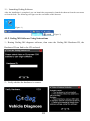
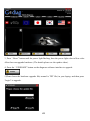
11,Launching Godiag Software
After the installation is completed, you can launch the programm by launch the shortcut from the start meau
or from the desk. The following two figure are the screetshots of the shortcut.
{Figure 1}
{Figure 2}
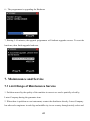
4.1.2 Godiag M8 Software Using Instructions
1,Runing Godiag M8 diagnose software, then enter the Godiag M8 Hardware ID, the
Hardware ID can find in the CD enclosed.
2,Verify whether the hardware is connect.
23
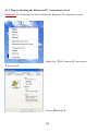
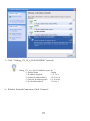
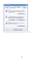
4.1.3 Ways to checking the Hardware/PC Connection is Good.
Important! The following is to check whether the Hardware/PC connection is good .
Right click 【My Computer】, then choose
【Properties】
Choose【Hardware】
24
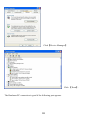
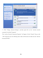
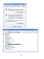
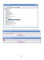
Click【Device Manager】
Click 【Ports】.
The Hardware/PC connection is good if the following port appears.
25
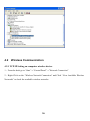
4.2
Wireless Communication
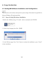
4.2.1 TCP/IP Setting on computer wireless device.
1,From the desk go to “Start”→“Control Panel”→”Network Connection”
2,Right Click on the “Wireless Network Connection” and Click “View Available Wireless
Networks” to check the available wireless networks.
26
3,Click“Godiag_172_16_6_D101G249P001” network
″Godiag_172_16_6_D101G249P001 means for ″
⊙ Product Name
⊙ IP Address Segment
⊙ Godiag IP Address(D101)
⊙ Gateway IP Address(g249)
⊙ PC IP Address(P001)
4,Wireless Network Connection, Click “Connect”.
27
: Godiag
: 172_16_6
:172.16.6.101
:172.16.6.249
:172.16.6.1
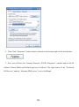
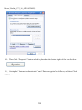
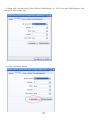
5,Click” Change advanced Settings”, and then right click on the “wireless network
connection” and click “Properties”.
The “wireless Network Connection Properties” will appear .On the “General” tab go to the
“This Connection uses the following items:”and scroll down the list and select the “Internet
Protocol(TCP/IP).”
28
.
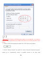
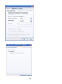
6,Then Click “Properties” button which is placed on the bottom right of the item list box.
7,Now you will have the “Internet Protocol (TCP/IP) Properties” window and set the IP
address, Subnet Mask and Default gateway as follows. The input boxes of the “Preferred
DNS server” and the “Alternate DNS server” is to be left blank.
29
Note
Important!! The IP address and Default gateway number is not unchangeable , every units have
different IP address and Default Gateway number. The details you can reference the sticker in outer
packing.
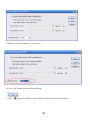
8,When you done with inputting the number click “OK” button on all windows.
9, On the “Wireless Network” tab under the “wireless Network Connection Properties”
window go to “Automatically connect to available network in the order listed
30
below( Godiag_172_16_6D101G249P).
10,Then Click “Properties” button which is placed on the bottom right of the item list box.
11, Setting the” Internet Authentication” and “Data encryption” as follows, and then Click
“OK” button.
31
32
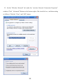
12,On the “Wireless Network” tab under the “wireless Network Connection Properties”
window, Click “ Advanced” Button on the bottom right of the item list box., and then setting
as follows. Click the “Close” and “OK” button.
33
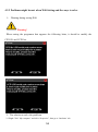
4.2.2 Problems might be met when Wifi Setting and the ways to solve .
1, Warning during setting Wifi.
Warning!
When runing the programm that appears the following hints, it should to modify the
CP210X and VCP Port.
2,The solution to solve the problems.
2.1 Rigth Click” My computer” and click “Properties” ,then go to “hardware’ tab.
34
2.2 Find “Device Manager” and then click,find the “CP210X” or”VCP” Port
35
36
2.3 Right click “Silicom Labs CP210X USB to URAT Bridge” or “VCP” Port, and Click”Properties” and
then go to “Port Setting” Tab.
2.4 Click “Advanced” Button
37
2.5 Modify “COM Port Number” to less than 10.
2.6 Click “OK” Button and compelete modifying.
2.7 Click
the button on the top of the window, and get the result after modifying.
38
2.8 When appearing the following indication when modifying serial port, please Choose“YES” button.
39
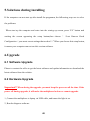
5.Solutions during installing
If the computer can not start up after install the programm, the followsing ways are to solve
the problems:
When start up the computer and enter into the staring up screen, press “F8” button and
waiting the screen appearing the setup button,then choose “ ( Last Known Good
Configuration(your most recent settings that worked))”.When you choose this setup button,
it means your computer can not run this version software.
6.Upgrade
6.1 Software Upgrade
Please to contact the seller to get the latest software and update information or download the
latest software from the website.
6.2 Hardware Upgrade
Important!! When during the upgrade, you must keep the power on all the time. If the
power off during upgrade, it will make the multiplexer broken or cannot upgrade.
1, Connect the multiplexer to laptop via USB cable, and insure the light is on.
2, Run the diagnose software.
40
3, Press “ Reset” button until the power light flashing, then the power light color to blue color.
After then can upgrade hardware.( The details please see the update video).
4, Press the “ UPGRADE” button on the diagnose software interface to upgrade.
5,Please brose the hardware upgrade file( normal is TXT file) in your laptop, and then press
“begin” to upgrade.
41
6,The programmer is upgrading the Hardware
7, Waiting 5-10 minutes, the upgrade programmer will indicate upgrade success. To reset the
hardware, then finish upgrade hardware.
7. Maintenance and Service
7.1 Limit Range of Maintenance Service
1. Problem caused by the quality of the machine in correct use can be partially solved by
Latest Company during the guarantee time.
2. When there is problem on our instrument, contact the distributor directly. Latest Company
has after sales engineers in each big and middle city in our country through strictly select and
42
excellent training, which will offer high efficiency and good quality service.
3. Guarantee time refers to the period Latest Company sells the product. Detailed guarantee
information consult system record of Latest Company.
4. Users keep the guarantee card and purchasing voucher distributor open when sell instrument
carefully. When the instruments need to be repaired, the vouchers mentioned above are
regarded as guarantee proof.
5. Register the instrument in time. Guarantee time start from the register date system record.
6. Repaired instrument still enjoy maintenance service in warranty time. If warranty time will
be end in three months, replaced spare parts enjoy three-month maintenance since replace.
7. Spare parts replaced in maintenance period belong to Latest Company.
8. Users should take responsibility for the safety of data. Before maintenance, users backup the
data and program automatically. Latest Company and our distributors don’t take any
responsibility for destruction or loss of data, program or memory medium.
7.2 Out of Guarantee Range
1. Technology problem of non-hardware
1. Users replace components by themselves or the components not belong to Godiag and they
don’t buy from Godiag or our distributors.
2. Consume material(such as instrument appearance,natural consume and aging caused by
inserting and taking out components)
3. Trouble and destruction caused by wrong installation, operation (for example, pull out data
cable with electricity), or work condition which is not suitable for instrument(such as too
high or too low temperature, too humidity or dryness, too high altitude, unstable voltage or
43
current, ground voltage too big )
4. Destruction caused by accident, abuse (including excess working load), misuse.
5. Destruction caused by keeping improperly, such as rat scourge, liquid in leakage.
6. Destruction caused by using self-program or non-publicly publishing software.
7. Computer virus infected by improper maintenance.
8. Trouble and destruction caused by installation and using non-standard extension card.
9. Trouble and destruction caused by removing and repairing without technical people’s
advice or self-changing or abusing.
10.The trouble or destruction caused by human beings or natural disaster.
THANKS FOR USING GODIAG PRODUCTS!
44