1
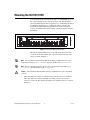
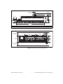
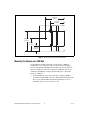
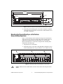
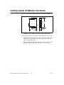
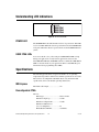
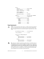
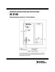
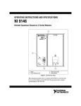
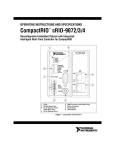
OPERATING INSTRUCTIONS AND SPECIFICATIONS NI 9157/9159 Reconfigurable Embedded Chassis with Integrated MXI-Express (x1) 2 1 NI 915X MXI-Express RIO POWER P USER FPGA1 USER FPGA2 USER FPGA3 OFF 6 C V2 LINK 3 DOWNSTREAM V1 LINK UPSTREAM INPUT 9-30 V 35W MAX NO FPGA APP USER FPGA1 USER FPGA2 USER FPGA3 4 C 5 1 2 3 LEDs Upstream Port MXI-Express LINK LEDs 4 5 6 Downstream Port Power Connector DIP Switches Figure 1. NI 9157/9159 This document describes how to connect the NI 9157/9159 to a MXI-Express host and one or more other chassis, and how to use the features of the NI 9157/9159. This document also contains specifications for the NI 9157/9159. Safety Guidelines Operate the NI 9157/9159 only as described in these operating instructions. Safety Guidelines for Hazardous Locations The NI 9157/9159 is suitable for use in Class I, Division 2, Groups A, B, C, D, T4 hazardous locations; Class 1, Zone 2, AEx nA IIC T4 and Ex nA IIC T4 hazardous locations; and nonhazardous locations only. Follow these guidelines if you are installing the NI 9157/9159 in a potentially explosive environment. Not following these guidelines may result in serious injury or death. Caution Do not disconnect the power supply wires and connectors from the controller unless power has been switched off. Caution Substitution of components may impair suitability for Class I, Division 2. For Zone 2 applications, install the system in an enclosure rated to at least IP 54 as defined by IEC 60529 and EN 60529. Caution Special Conditions for Hazardous Locations Use in Europe Some chassis have been evaluated as Ex nA IIC T4 equipment under DEMKO Certificate No. 07 ATEX 0626664X. Each such chassis is marked II 3G and is suitable for use in Zone 2 hazardous locations, in ambient temperatures of 0 Ta 55 °C. Special Conditions for Marine Applications Some chassis are Lloyd’s Register (LR) Type Approved for marine applications. To verify Lloyd’s Register certification, visit ni.com/ certification and search for the LR certificate, or look for the Lloyd’s Register mark on the chassis. To meet radio frequency emission requirements for marine applications, use shielded cables and install the system in a metal enclosure. Suppression ferrites must be installed on power supply inputs to modules. Power supply and module cables must be separated on opposite sides of the enclosure and must enter and exit through opposing enclosure walls. Caution NI 9157/9159 Operating Instructions and Specifications 2 ni.com What You Need to Install the NI 9157/9159 ❑ NI 9157/9159 reconfigurable embedded chassis with integrated MXI-Express (x1) ❑ One of the following MXI-Express (x1) host systems – PXI system with MXI-Express device installed – PC with MXI-Express PCI or PCIe device installed – NI Industrial Controller Note The NI 9157/9159 requires a host system with a PCI Express clock that complies with the PCI Express Specification. The NI 9157/9159 may not be compatible with systems using noncompliant clocks, particularly clocks with peak frequencies higher than 100 MHz. For more information about PCI Express clock compatibility with the NI 9157/9159, go to ni.com/info and enter the Info Code 915xclock. ❑ C Series I/O modules ❑ MXI-Express (x1) cable(s) up to 7 m long ❑ DIN rail mount kit (for DIN rail mounting only) ❑ Panel mount kit (for panel mounting only) ❑ Three M4 or number 8 panhead screws (for mounting the chassis without one of the listed mounting kits) ❑ Number 2 Phillips screwdriver ❑ Power supply ❑ MXI-Express (x1) for PXI Express User Manual Notes Visit ni.com/info and enter the Info Code rdsoftwareversion to determine which software you need to use the NI 9157/9159. © National Instruments Corporation 3 NI 9157/9159 Operating Instructions and Specifications Mounting the NI 9157/9159 You can mount the chassis horizontally either on a 35 mm DIN rail or on a flat, vertical, metallic surface such as a panel or wall. The maximum allowable ambient temperature for operation is 55 °C. Mounting the chassis in a different orientation or on a nonmetallic surface can reduce the maximum allowable ambient temperature and can affect the typical accuracy of modules in the chassis. Figure 2 shows the chassis mounted horizontally. Up Figure 2. NI 9157/9159 Mounted Horizontally Measure the ambient temperature at each side of the chassis, 63.5 mm (2.5 in.) from the side and 50.8 mm (2 in.) forward from the rear of the chassis, as shown in Figure 3. Note For more information about how different mounting configurations can cause temperature derating, go to ni.com/info and enter the Info Code criomounting. Note For more information about typical accuracy specifications for modules, go to ni.com/info and enter the Info Code criotypical. Your installation must meet the following requirements for space and cabling clearance: Caution • Allow 50.8 mm (2 in.) on the top and the bottom of the chassis for air circulation. • Allow 50.8 mm (2 in.) in front of modules for cabling clearance for common connectors, such as the 10-terminal, detachable screw terminal connector, as shown in Figure 3. NI 9157/9159 Operating Instructions and Specifications 4 ni.com 29 mm (1.14 in.) Cabling Clearance 50.8 mm (2 in.) 63.5 mm (2.50 in.) 48.4 mm (1.91 in.) 63.5 mm (2.50 in.) 89.4 mm (3.52 in.) 50.8 mm (2 in.) 1 50.8 mm (2 in.) 1 1 406.3 mm (16 in.) Measure ambient temperature here. Figure 3. NI 9157/9159, Bottom View with Dimensions Cooling Outline 50.8 mm (2 in.) 132.6 mm (5.22 in.) 165.1 mm (6.50 in.) 28.0 mm (1.10 in.) 36.4 mm (1.43 in.) 87.3 mm (3.44 in.) 51.7 mm (2.04 in.) 4.1 mm (0.16 in.) Cooling Outline 50.8 mm (2 in.) Figure 4. NI 9157/9159, Front View with Dimensions © National Instruments Corporation 5 NI 9157/9159 Operating Instructions and Specifications 68.2 mm (2.68 in.) 51.4 mm (2.02 in.) 69.5 mm (2.74 in.) 44.1 mm (1.74 in.) 18.7 mm (0.74 in.) Figure 5. NI 9157/9159, Side View with Dimensions Mounting the Chassis on a DIN Rail Use the DIN rail mounting method if you already have a DIN rail configuration or if you need to be able to remove the chassis quickly. You can order the NI 9916 DIN rail mount kit if you want to mount the chassis on a DIN rail. You need one clip for mounting the chassis on a standard 35 mm DIN rail. Complete the following steps to mount the chassis on a DIN rail. 1. Fasten the DIN rail clip to the chassis using a number 2 Phillips screwdriver and three M4 50 screws. National Instruments provides these screws with the DIN rail mount kit. Tighten the screws to a maximum torque of 1.3 N m (11.5 lb in.). NI 9157/9159 Operating Instructions and Specifications 6 ni.com Figure 6. Installing the DIN Rail Clip on the NI 9157/9159 2. Insert one edge of the DIN rail into the deeper opening of the DIN rail clip, as shown in Figure 7. 1 2 3 1 DIN Rail Clip 2 DIN Rail Spring 3 DIN Rail Figure 7. One Edge of the DIN Rail Inserted in a Clip 3. © National Instruments Corporation Press down firmly on the chassis to compress the spring until the clip locks in place on the DIN rail. 7 NI 9157/9159 Operating Instructions and Specifications Mounting the Chassis on a Flat Surface Using the NI 9907 Panel Mount Kit Panel or wall mounting is the best method for high shock and vibration applications. You can use the NI 9907 panel mount kit to mount the NI 9157/9159 on a flat surface. Complete the following steps. 1. Fasten the panel mounting plate to the chassis using a number 2 Phillips screwdriver and six M4 10 screws. National Instruments provides these screws with the panel mount kit. Tighten the screws to a maximum torque of 1.3 N m (11.5 lb in.). Figure 8. Installing the Panel Mounting Plate on the NI 9157/9159 NI 9157/9159 Operating Instructions and Specifications 8 ni.com 457.20 mm (18 in.) 438.15 mm (17.250 in.) 9.53 mm (0.375 in.) 25.25 mm (0.994 in.) 25.70 mm (1.012 in.) 31.75 mm (1.250 in.) 63.50 mm (2.500 in.) 88.14 mm (3.470 in.) 17.40 mm (0.685 in.) Figure 9. Dimensions of NI 9157/9159 with Panel Mounting Plate Installed 2. Fasten the panel mounting plate to the surface using the screwdriver and screws that are appropriate for the surface. The maximum screw size is M4 or number 8. Mounting the Chassis Directly on a Flat Surface Using the Mounting Holes Panel or wall mounting is the best method for high shock and vibration applications. If you do not have the NI 9907 panel mount kit and do not require the portability that the NI 9907 affords, you can mount the NI 9157/9159 directly on a flat surface using the three mounting holes. Complete the following steps. 1. Align the chassis on the surface. 2. Fasten the chassis to the surface using three M4 or number 8 screws. National Instruments does not provide these screws with the chassis. Figure 10. Mounting the NI 9157/9159 Directly on a Flat Surface Caution Make sure that no I/O modules are in the chassis before removing it from the surface. © National Instruments Corporation 9 NI 9157/9159 Operating Instructions and Specifications Installing C Series I/O Modules in the Chassis Figure 11 shows the mechanical dimensions of C Series I/O modules. 88.1 mm (3.47 in.) 70.7 mm (2.78 in.) 22.9 mm (0.9 in.) Figure 11. C Series I/O Module, Front and Side View with Dimensions Complete the following steps to install a C Series I/O module in the chassis. 1. Make sure that no I/O-side power is connected to the I/O module. If the system is in a nonhazardous location, the chassis power can be on when you install I/O modules. 2. Align the I/O module with an I/O module slot in the chassis as shown in Figure 12. The module slots are labeled 1 to 14, left to right. NI 9157/9159 Operating Instructions and Specifications 10 ni.com 1 2 1 Insertion Groove 2 Latch Figure 12. Installing an I/O Module in the Chassis 3. Squeeze the latches and insert the I/O module into the module slot. 4. Press firmly on the connector side of the I/O module until the latches lock the I/O module into place. 5. Repeat these steps to install additional I/O modules. © National Instruments Corporation 11 NI 9157/9159 Operating Instructions and Specifications Removing I/O Modules from the Chassis Complete the following steps to remove a C Series I/O module from the chassis. 1. Make sure that no I/O-side power is connected to the I/O module. If the system is in a nonhazardous location, the chassis power can be on when you remove I/O modules. 2. Squeeze the latches on both sides of the module and pull the module out of the chassis. Wiring Power to the Chassis The NI 9157/9159 requires an external power supply that meets the specifications in the Power Requirements section. The NI 9157/9159 filters and regulates the supplied power and provides power for all of the I/O modules. You must connect a power supply to at least one pair of V and C terminals. Optionally, you can connect a second power supply to the other pair of V and C terminals. The chassis draws power from the power supply with the higher voltage. The NI 9157/9159 has one layer of reverse-voltage protection. Complete the following steps to connect a power supply to the chassis. 1. Connect the positive lead of the power supply to the V1 or V2 terminal of the COMBICON connector shipped with the NI 9157/9159. 2. Connect the negative lead of the power supply to one of the C terminals of the COMBICON connector. 3. Optionally you can connect the positive lead of another power supply to the other V terminal and the negative lead to one of the C terminals. 4. Install the COMBICON connector on the front panel of the NI 9157/9159. Note The chassis draws power from either V1 or V2 depending on which terminal has a higher voltage. It does not draw power from both terminals. The chassis switches between V1 and V2 without affecting operation. Note If you prefer for the chassis to draw power from one power supply, you must ensure that the voltage of that power supply, measured at the chassis power connector, is at least 500 mV higher than the voltage of the other power supply. The C terminals are internally connected to each other. If you use two power supplies, make sure that they share a common ground. Caution NI 9157/9159 Operating Instructions and Specifications 12 ni.com Caution The C terminals are internally connected to the body of the chassis to prevent a faulty ground connection from causing the chassis ground to float. If you reverse the input voltage, the positive input voltage is connected directly to the chassis. The chassis has built-in reversed-voltage protection, but reversed voltage can damage connected peripherals if the chassis ground is not reliably connected to earth ground. Do not tighten or loosen the terminal screws on the power connector while the power connector is plugged into the chassis or while the power supply is on. Caution Connecting One or More NI 9157/9159 Chassis to the MXI-Express Host System Complete the following steps to connect one or more NI 9157/9159 chassis to a MXI-Express host system. 1. Make sure the MXI-Express host system is set up and configured as described in the MXI-Express (x1) for PXI Express User Manual. 2. If the MXI-Express host system is powered up, power it down. 3. If the NI 9157/9159 is powered up, power it down. 4. Use a MXI-Express cable to connect the MXI-Express host system to the Upstream port of the first NI 9157/9159 in the chain. 5. Use a MXI-Express cable to connect the Downstream port of the first NI 9157/9159 to the Upstream port of the next NI 9157/9159 in the chain. Note The maximum number of NI 9157/9159 chassis in a chain depends on the system configuration. For example, a PXI system with an NI PXI-8196 controller can support four chassis per chain. Different types of systems may support more or fewer chassis per chain. For more information about how different system configurations can affect the maximum number of chassis in a chain, go to ni.com/info and enter the Info Code 915xchain. 6. Power up all of the connected NI 9157/9159 chassis. 7. Power up the MXI-Express host system. All connected NI 9157/9159 chassis must have power connected before the host system is powered up. The BIOS and OS of the host system must detect all bus segments on the chassis side in order to configure the PCI hierarchy. Powering connected chassis up or down while the host system is running can cause system hangs and data corruption. Caution Caution Do not remove MXI-Express cables while power is connected. Doing so can cause hangs or application errors. If a cable becomes unplugged, plug it back in and reboot. © National Instruments Corporation 13 NI 9157/9159 Operating Instructions and Specifications Chassis Powerup Options Table 1 lists the reset options available for the NI 9157/9159. These options determine how the chassis behaves when it is powered on in various conditions. Use the RIO Device Setup utility to select reset options. Access the RIO Device Setup utility by selecting Start»All Programs»National Instruments»NI-RIO»RIO Device Setup. Table 1. Chassis Powerup Options Powerup Option Behavior Do Not Autoload VI Does not load the FPGA bit stream from flash memory. Autoload VI on device powerup Loads the FPGA bit stream from flash memory to the FPGA when the chassis powers on. If you want the NI 9157/9159 to autoload and run a VI at powerup, you must also configure the VI to autoload before you compile it. For more information about autoloading VIs, refer to LabVIEW FPGA Module Help. Checking MXI-Express LINK LEDs for Status After powering on the chassis and host system, check the MXI-Express LINK LEDs to ensure that all connected systems are linked and communicating properly. The MXI-Express LINK LEDs of the NI 9157/9159 indicate the following: Table 2. NI 9157/9159 MXI-Express LINK LED Indications LINK LED Appearance Meaning Off Chassis power is off. Solid yellow Link is not established. Solid green Link is established. Blinking yellow PCI Express clock is incompatible with NI 9157/9159. Note For information about PCI Express clock compatibility with the NI 9157/9159, go to ni.com/info and enter the Info Code 915xclock. NI 9157/9159 Operating Instructions and Specifications 14 ni.com Powering Down the MXI-Express System Always power down the host system before powering down any connected NI 9157/9159 chassis. When the host system is powered down, the order in which connected NI 9157/9159 chassis are powered down is not important. Configuring DIP Switches OFF NO FPGA APP USER FPGA1 USER FPGA2 USER FPGA3 Figure 13. DIP Switches All of the DIP switches are in the OFF position when the chassis is shipped from National Instruments. NO FPGA APP Switch Push the NO FPGA APP switch to the ON position to prevent a LabVIEW FPGA application from loading at startup. The NO FPGA APP switch overrides the chassis powerup options described in the Chassis Powerup Options section. After startup you can download to the FPGA from software regardless of switch position. USER FPGA Switches You can define the USER FPGA switches for your application. Use the LabVIEW FPGA Module and NI-RIO software to define the USER FPGA switches to meet the needs of your application. Refer to LabVIEW Help for information about programming these switches. © National Instruments Corporation 15 NI 9157/9159 Operating Instructions and Specifications Understanding LED Indications POWER P USER FPGA1 USER FPGA2 USER FPGA3 Figure 14. NI 9157/9159 LEDs POWER LED The POWER LED is lit while the NI 9157/9159 is powered on. This LED is a bi-color LED. When the chassis is powered from V1, the POWER LED is lit green. When the chassis is powered from V2, the POWER LED is lit yellow. USER FPGA LEDs You can use the bi-color, yellow and green USER FPGA LEDs to help debug your application or easily retrieve application status. Use the LabVIEW FPGA Module and NI-RIO software to define the USER FPGA LEDs to meet the needs of your application. Refer to LabVIEW Help for information about programming these LEDs. Specifications The following specifications are typical for the 0 to 55 °C operating temperature range unless otherwise noted. These specifications are for the NI 9157/9159 reconfigurable embedded chassis only. For I/O module specifications, refer to the module operating instructions. MXI-Express Maximum cable length ...........................7 m Reconfigurable FPGA NI 9157 FPGA type .......................................Virtex-5 LX85 Number of flip-flops........................51,840 Number of 6-input LUTs.................51,840 Number of DSP48 slices (25 18 multipliers)........................48 Embedded block RAM ....................3,456 kbits NI 9157/9159 Operating Instructions and Specifications 16 ni.com NI 9159 FPGA type ...................................... Virtex-5 LX110 Number of flip-flops ....................... 69,120 Number of 6-input LUTs ................ 69,120 Number of DSP48 slices (25 18 multipliers) ....................... 64 Embedded block RAM ................... 4,608 kbits Timebases............................................... 40, 80, 120, 160, or 200 MHz Accuracy ......................................... ±100 ppm (max) Frequency dependent jitter (peak-to-peak) 40 MHz .................................... 250 ps 80 MHz .................................... 422 ps 120 MHz .................................. 422 ps 160 MHz .................................. 402 ps 200 MHz .................................. 402 ps Power Requirements You must use the NI 9157/9159 with a 9 to 30 VDC output, UL Listed, limited power source (LPS) supply. The power supply must bear the UL Listed and LPS marks. The power supply must also meet any safety and compliance requirements for the country of use. Caution Recommended power supply ................. 55 W, 30 VDC max Voltage requirement............................... 9 to 30 V Chassis power consumption/dissipation NI 9157 With no I/O modules ............... 14.4 W (max) With 14 I/O modules ............... 30.7 W (max) NI 9159 With no I/O modules ............... 16.25 W (max) With 14 I/O modules ............... 32.7 W (max) Note The power consumption specifications in this document are maximum values for a LabVIEW FPGA application compiled at 80 MHz. Your application power requirements may be different. To calculate the power requirements of the NI 9157/9159, add the power consumption/dissipation for the chassis and the I/O modules you are using. Keep in mind that the resulting total power consumption is a maximum value and that the NI 9157/9159 may require less power in your application. For more information about the I/O module power requirements, refer to the module operating instructions. © National Instruments Corporation 17 NI 9157/9159 Operating Instructions and Specifications Physical Characteristics If you need to clean the chassis, wipe it with a dry towel. Screw-terminal wiring ............................12–18 AWG copper conductor wire with 10 mm (0.39 in.) of insulation stripped from the end Torque for screw terminals.....................0.5 to 0.6 N · m (4.4 to 5.3 lb · in.) Chassis weight ........................................2,231 g (78.7 oz) Environmental The NI 9157/9159 is intended for indoor use only. Operating temperature (IEC-60068-2-1 and IEC-60068-2-2) .....0 °C to 55 °C Note Refer to the mounting instructions in the Mounting the NI 9157/9159 section of this document. Failure to follow the mounting instructions in that section can cause temperature derating. For more information about mounting configurations and temperature derating, go to ni.com/info and enter the Info Code criomounting. Storage temperature (IEC-60068-2-1 and IEC-60068-2-2) .....–40 °C to 85 °C Ingress protection ...................................IP 40 Operating humidity (IEC-60068-2-56) ...................................10 to 90% RH, noncondensing Storage humidity (IEC-60068-2-56) ...................................5 to 95% RH, noncondensing Maximum altitude...................................2,000 m Pollution Degree (IEC 60664) ................2 NI 9157/9159 Operating Instructions and Specifications 18 ni.com Shock and Vibration To meet these specifications, you must panel mount the chassis and affix ferrules to the ends of the terminal lines. Operating vibration, random (IEC 60068-2-64)...................... 5 grms, 10 to 500 Hz Operating vibration, sinusoidal (IEC 60068-2-6).................... 5 g, 10 to 500 Hz Operating shock (IEC 60068-2-27)........ 30 g, 11 ms half sine, 50 g, 3 ms half sine, 18 shocks at 6 orientations Safety Safety Voltages Connect only voltages that are within these limits. V-to-C .................................................... 30 V max, Measurement Category I Measurement Category I is for measurements performed on circuits not directly connected to the electrical distribution system referred to as MAINS voltage. MAINS is a hazardous live electrical supply system that powers equipment. This category is for measurements of voltages from specially protected secondary circuits. Such voltage measurements include signal levels, special equipment, limited-energy parts of equipment, circuits powered by regulated low-voltage sources, and electronics. Do not connect to signals or use for measurements within Measurement Categories II, III, or IV. Caution Electromagnetic Compatibility This product meets the requirements of the following EMC standards for electrical equipment for measurement, control, and laboratory use: • EN 61326 (IEC 61326): Class A emissions; Industrial immunity • EN 55011 (CISPR 11): Group 1, Class A emissions • AS/NZS CISPR 11: Group 1, Class A emissions • FCC 47 CFR Part 15B: Class A emissions • ICES-001: Class A emissions © National Instruments Corporation 19 NI 9157/9159 Operating Instructions and Specifications Note For the standards applied to assess the EMC of this product, refer to the Online Product Certification section. Note For EMC compliance, operate this product according to the documentation. CE Compliance This product meets the essential requirements of applicable European Directives as follows: • 2006/95/EC; Low-Voltage Directive (safety) • 2004/108/EC; Electromagnetic Compatibility Directive (EMC) Online Product Certification Refer to Declaration of Conformity (DoC) for this product for additional regulatory compliance information. To obtain product certifications and the DoC for this product, visit ni.com/certification, search by model number or product line, and click the appropriate link in the Certification column. Environmental Management NI is committed to designing and manufacturing products in an environmentally responsible manner. NI recognizes that eliminating certain hazardous substances from our products is beneficial to the environment and to NI customers. For additional environmental information, refer to the NI and the Environment Web page at ni.com/environment. This page contains the environmental regulations and directives with which NI complies, as well as other environmental information not included in this document. Waste Electrical and Electronic Equipment (WEEE) EU Customers At the end of the product life cycle, all products must be sent to a WEEE recycling center. For more information about WEEE recycling centers, National Instruments WEEE initiatives, and compliance with WEEE Directive 2002/96/EC on Waste Electrical and Electronic Equipment, visit ni.com/environment/weee. ⬉ᄤֵᙃѻક∵ᶧࠊㅵ⧚ࡲ⊩ ˄Ё RoHS˅ Ёᅶ᠋ National Instruments ヺড়Ё⬉ᄤֵᙃѻકЁ䰤ࠊՓ⫼ᶤѯ᳝ᆇ⠽䋼ᣛҸ (RoHS)DŽ ݇Ѣ National Instruments Ё RoHS ড়㾘ᗻֵᙃˈ䇋ⱏᔩ ni.com/environment/rohs_chinaDŽ (For information about China RoHS compliance, go to ni.com/environment/rohs_china.) NI 9157/9159 Operating Instructions and Specifications 20 ni.com Hazardous Locations U.S. (UL) ................................................Class I, Division 2, Groups A, B, C, D, T4; Class I, Zone 2, AEx nA IIC T4 Canada (C-UL) .......................................Class I, Division 2, Groups A, B, C, D, T4; Class I, Zone 2, Ex nA IIC T4 Europe (DEMKO) ..................................Ex nA IIC T4 Where to Go for Support National Instruments corporate headquarters is located at 11500 North Mopac Expressway, Austin, Texas, 78759-3504. National Instruments also has offices located around the world to help address your support needs. For telephone support in the United States, create a service request at ni.com/support and follow the calling instructions or dial 512 795 8248. For telephone support outside the Untied States, contact your local branch office: Australia 1800 300 800, Austria 43 662 457990-0, Belgium 32 (0) 2 757 0020, Brazil 55 11 3262 3599, Canada 800 433 3488, China 86 21 5050 9800, Czech Republic 420 224 235 774, Denmark 45 45 76 26 00, Finland 358 (0) 9 725 72511, France 01 57 66 24 24, Germany 49 89 7413130, India 91 80 41190000, Israel 972 3 6393737, Italy 39 02 41309277, Japan 0120-527196, Korea 82 02 3451 3400, Lebanon 961 (0) 1 33 28 28, Malaysia 1800 887710, Mexico 01 800 010 0793, Netherlands 31 (0) 348 433 466, New Zealand 0800 553 322, Norway 47 (0) 66 90 76 60, Poland 48 22 328 90 10, Portugal 351 210 311 210, Russia 7 495 783 6851, Singapore 1800 226 5886, Slovenia 386 3 425 42 00, South Africa 27 0 11 805 8197, Spain 34 91 640 0085, Sweden 46 (0) 8 587 895 00, Switzerland 41 56 2005151, Taiwan 886 02 2377 2222, Thailand 662 278 6777, Turkey 90 212 279 3031, United Kingdom 44 (0) 1635 523545 © National Instruments Corporation 21 NI 9157/9159 Operating Instructions and Specifications LabVIEW, National Instruments, NI, ni.com, the National Instruments corporate logo, and the Eagle logo are trademarks of National Instruments Corporation. Refer to the Trademark Information at ni.com/trademarks for other National Instruments trademarks. Other product and company names mentioned herein are trademarks or trade names of their respective companies. For patents covering National Instruments products/technology, refer to the appropriate location: Help»Patents in your software, the patents.txt file on your media, or the National Instruments Patent Notice at ni.com/patents. © 2010 National Instruments Corporation. All rights reserved. 375184B-01 Jul10