1
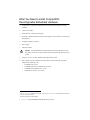
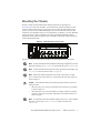
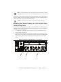
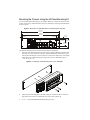
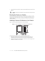
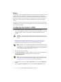
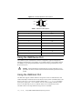
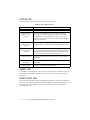
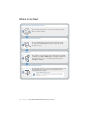
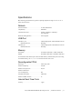
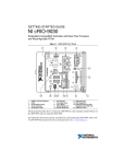
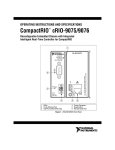
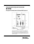
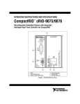
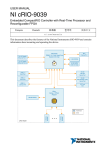
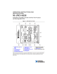
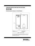
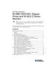
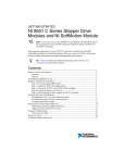
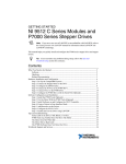
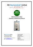
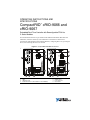
OPERATING INSTRUCTIONS AND SPECIFICATIONS CompactRIO™ cRIO-9066 and cRIO-9067 Embedded Real-Time Controller with Reconfigurable FPGA for C Series Modules This document describes how to get started with the National Instruments cRIO-9066 and cRIO-9067, referred to inclusively as the cRIO-906x. This document contains device specifications and information about installing hardware, configuring device I/O, powering the device, and connecting the device to a network. Figure 1. CompactRIO cRIO-906x Front Panel POWER STATUS USER1 USER FPGA1 2 POWER STATUS USER1 USER FPGA1 2 3 1 1 C INPUT 9-30 V 25 W MAX 8 ACT/ LINK 7 10/100/ 1000 2 ACT/ LINK 10/100/ 1000 RESET V 1 C 5 INPUT 9-30 V 25 W MAX 6 RS-232 Serial Port LEDs USB Device Port RJ-45 Ethernet Port 2 (Not available on the cRIO-9066) 8 ACT/ LINK 7 5 6 7 8 DO NOT SEPARATE CABLES WHEN ENERGIZED IN HAZARDOUS LOCATIONS V DO NOT SEPARATE CABLES WHEN ENERGIZED IN HAZARDOUS LOCATIONS 1 RESET 1 2 3 4 3 10/100/ 1000 6 RJ-45 Ethernet Port 1 USB Host Port Power Connector Reset Button 4 5 Safety Guidelines Do not operate the cRIO-906x in a manner not specified in these operating instructions. Product misuse can result in a hazard. You can compromise the safety protection built into the product if the product is damaged in any way. If the product is damaged, return it to National Instruments for repair. Caution Safety Guidelines for Hazardous Locations The cRIO-906x is suitable for use in only Class I, Division 2, Groups A, B, C, D, T4 hazardous locations; Class 1, Zone 2, AEx nA IIC T4 and Ex nA IIC T4 hazardous locations; and nonhazardous locations. Follow these guidelines if you are installing the cRIO-906x in a potentially explosive environment. Not following these guidelines may result in serious injury or death. Do not disconnect the power supply wires and connectors from the controller unless power has been switched off. Caution Caution Substitution of components may impair suitability for Class I, Division 2. For Zone 2 applications, install the CompactRIO system in an enclosure rated to at least IP 54 as defined by IEC 60529 and EN 60529. Caution The USB port requires NI industrial USB cables with locking screws, NI part number 152166-XX or 15788A-01. The cable must pass through conduit or cable gland to a nonhazardous location. Do not disconnect the cable unless the cRIO-906x is powered off or the area is known to be nonhazardous. Caution Special Conditions for Hazardous Locations Use in Europe Some chassis have been evaluated as Ex nA IIC T4 Gc equipment under DEMKO Certificate No. 12 ATEX 1202658X. Each such chassis is marked II 3G and is suitable for use in Zone 2 hazardous locations in ambient temperatures of -20 °C ≤ Ta ≤ 55 °C. You must ensure that transient disturbances do not exceed 140% of the rated voltage. Caution Mount the system in an ATEX certified enclosure with a minimum ingress protection rating of at least IP 54 as defined in IEC/EN 60529 and use the system in an environment of not more than Pollution Degree 2. Caution Caution The enclosure must have a door or cover accessible only by the use of a tool. 2 | ni.com | CompactRIO cRIO-9066/cRIO-9067 Operating Instructions Electromagnetic Compatibility Guidelines This product was tested and complies with the regulatory requirements and limits for electromagnetic compatibility (EMC) stated in the product specifications. These requirements and limits provide reasonable protection against harmful interference when the product is operated in the intended operational electromagnetic environment. This product is intended for use in industrial locations. However, harmful interference may occur in some installations, when the product is connected to a peripheral device or test object, or if the product is used in residential or commercial areas. To minimize interference with radio and television reception and prevent unacceptable performance degradation, install and use this product in strict accordance with the instructions in the product documentation. Furthermore, any modifications to the product not expressly approved by National Instruments could void your authority to operate it under your local regulatory rules. To ensure the specified EMC performance, operate this product only with shielded cables and accessories. Caution Special Guidelines for Marine Applications Some products are Lloyd’s Register (LR) Type Approved for marine (shipboard) applications. To verify Lloyd’s Register certification for a product, visit ni.com/certification and search for the LR certificate, or look for the Lloyd’s Register mark on the product label. Caution In order to meet the EMC requirements for marine applications, install the product in a shielded enclosure with shielded and/or filtered power and input/output ports. In addition, take precautions when designing, selecting, and installing measurement probes and cables to ensure that the desired EMC performance is attained. CompactRIO cRIO-9066/cRIO-9067 Operating Instructions | © National Instruments | 3 What You Need to Install CompactRIO Reconfigurable Embedded Hardware NI cRIO-906x reconfigurable embedded chassis with integrated intelligent real-time controller C Series I/O modules Panel, DIN rail, or desktop mounting kit Three M4 or number 8 flathead screws (for mounting the chassis without one of the listed mounting kits) A number 2 Phillips screwdriver Power supply1 USB A-to-B cable National Instruments recommends using a locking USB cable, such as part number 157788-01, in order to meet the shock and vibration specifications of this product. Caution Category 5 (CAT-5) or better shielded, twisted-pair Ethernet cable Host computer running a Windows operating system, with the following NI software installed in the following order: 1 2 3 4 • LabVIEW 20142 or later • LabVIEW Real-Time (RT) Module 2014 2 or later • LabVIEW FPGA Module 2014 2, 3 or later • NI-RIO Device Drivers 14.0 2 or later Refer to the Power Requirements section. Visit ni.com/info and enter the Info Code rdsoftwareversion to view the latest list of software you can use with your device. Required to program on-board FPGA. | ni.com | CompactRIO cRIO-9066/cRIO-9067 Operating Instructions Mounting the Chassis In order to obtain the maximum allowable ambient temperature as specified in the Environmental section of this document, you must mount the chassis horizontally on a flat, vertical, metallic surface such as a panel or wall. You can mount the chassis directly to the surface or you can use the NI Panel Mounting Kit. You can also mount the chassis in other orientations, on a nonmetallic surface, on a 35-mm DIN rail, on a desktop, or in a rack. Mounting the chassis in these or other configurations can reduce the maximum allowable ambient temperature and can affect the typical accuracy of modules in the chassis. Figure 2 shows the chassis mounted horizontally. Figure 2. cRIO-906x Mounted Horizontally Up Figures 3 to 5 show the bottom, front, and side views with the dimensions of the chassis. Note For more information about how different mounting configurations can cause temperature derating, visit ni.com/info and enter the Info Code criomounting. Note For more information about typical accuracy specifications for modules, visit ni.com/info and enter the Info Code criotypical. Note Measure the ambient temperature at each side of the chassis, 63.5 mm (2.5 in.) from the side and 25.4 mm (1 in.) forward from the rear of the chassis, as shown in Figure 3. Caution Your installation must meet the following requirements for space and cabling clearance: • Allow 50.8 mm (2 in.) on the top and bottom of the chassis for air circulation, as shown in Figure 4. • Allow 50.8 mm (2 in.) in front of modules for cabling clearance for common connectors, such as the 10-terminal, detachable screw terminal connector, as shown in Figure 3. Note For information about the minimum cabling clearance for C Series modules with other connector types, visit ni.com/info and enter the Info Code rdcrioconn. CompactRIO cRIO-9066/cRIO-9067 Operating Instructions | © National Instruments | 5 Figure 3. cRIO-906x Bottom View with Dimensions Cabling Clearance 50.8 mm (2.00 in.) 50.8 mm (2.00 in.) 29.1 mm (1.14 in.) 2 1 63.5 mm (2.50 in.) 62.3 mm (2.45 in.) 2 25.4 mm (1.00 in.) 25.4 mm (1.00 in.) 63.5 mm (2.50 in.) 1 Chassis Grounding Screw 2 Location for Measuring Ambient Temperature Figure 4. cRIO-906x Front View with Dimensions 141.7 mm (5.58 in.) 47.2 mm (1.86 in.) 30.8 mm (1.21 in.) 47.0 mm (1.85 in.) 88.1 mm (3.47 in.) 272.8 mm (10.74 in.) 4.1 mm (0.16 in.) Figure 5. cRIO-906x Side View with Dimensions 44.1 mm (1.74 in.) 29.3 mm (1.15 in.) 14.1 mm (0.55 in.) 44.1 mm (1.73 in.) For more information about the dimensions of the system, including detailed dimensional drawings, visit ni.com/dimensions. Note 6 | ni.com | CompactRIO cRIO-9066/cRIO-9067 Operating Instructions Note For more information about mounting the chassis in environments with high shock and vibration, visit ni.com/info and enter the Info Code criomounting. The following sections contain instructions for the mounting methods. Before using any of these mounting methods, record the serial number from the back of the chassis. You will be unable to read the serial number after you have mounted the chassis. Caution Ensure that no I/O modules are in the chassis before mounting it. Mounting the Chassis Directly on a Flat Surface Using the Mounting Holes For environments with high shock and vibration, National Instruments recommends mounting the chassis directly on a flat, rigid surface using the mounting holes in the chassis. Complete the following steps to mount the chassis. 1. Use the dimensions shown in Figure 4 to prepare the surface for mounting the chassis. 2. Align the chassis on the surface. 3. Fasten the chassis to the surface using three M4 or number 8 screws appropriate for the surface, as shown in Figure 6. Screws must be longer than 19 mm (0.75 in.) to pass all the way through the chassis. National Instruments does not provide these screws with the chassis. Figure 6. Mounting the cRIO-906x Directly on a Flat Surface CompactRIO cRIO-9066/cRIO-9067 Operating Instructions | © National Instruments | 7 Mounting the Chassis Using the NI Panel Mounting Kit You can use the NI panel mounting kit, part number 782863-01, to mount the chassis on a flat surface. Ensure there is sufficient surface area prior to mounting by referring to the dimensions shown in Figure 7. Figure 7. Dimensions of cRIO-906x with Panel Mounting Plate Installed 355.6 mm (14.00 in.) 336.5 mm (13.25 in.) 9.5 mm (0.38 in.) 7.2 mm (0.29 in.) 17.6 mm (0.69 in.) 31.7 mm (1.25 in.) 88.1 mm (3.47 in.) 63.5 mm (2.50 in.) Complete the following steps to mount the chassis using the mounting kit. 1. Fasten the panel mounting plate to the chassis using a number 2 Phillips screwdriver and three M4 × 23 screws, as shown in Figure 8. National Instruments provides these screws with the panel mounting kit. You must use these screws because they are the correct depth and thread for the panel mounting plate. Tighten the screws to a maximum torque of 1.3 N · m (11.5 lb · in.). Figure 8. Installing the Panel Mounting Plate on the cRIO-906x 2. 8 Fasten the panel mounting plate to the surface using the screwdriver and screws that are appropriate for the surface. The maximum screw size is M5 or number 10. | ni.com | CompactRIO cRIO-9066/cRIO-9067 Operating Instructions Caution Ensure that no I/O modules are in the chassis before removing it from the surface. Mounting the Chassis on a DIN Rail You can use the NI 9915 DIN rail mounting kit, part number 779018-01, to mount the chassis on a standard 35-mm DIN rail. Complete the following steps to mount the chassis on a DIN rail. 1. Fasten the DIN rail clip to the chassis using a number 2 Phillips screwdriver and two M4 × 25 flathead screws, as shown in Figure 9. National Instruments provides these screws with the DIN rail mounting kit. Tighten the screws to a maximum torque of 1.3 N · m (11.5 lb · in.). Figure 9. Installing the DIN Rail Clip on the cRIO-906x 2. Insert one edge of the DIN rail into the deeper opening of the DIN rail clip, as shown in Figure 10. Figure 10. One Edge of the DIN Rail Inserted in a Clip 1 2 3 1 DIN Rail Clip 2 DIN Rail 3 DIN Rail Spring CompactRIO cRIO-9066/cRIO-9067 Operating Instructions | © National Instruments | 9 3. Press down firmly on the chassis to compress the spring until the clip locks in place on the DIN rail. Caution Ensure that no I/O modules are in the chassis before removing it from the DIN rail. Mounting the Chassis on a Desktop You can use the NI 9901 desktop mounting kit to mount the chassis on a desktop. You must install the adapter bracket using two M3 × 20 screws. The adapter bracket and the screws are included in the kit. Refer to the NI 9901 documentation for information about mounting the chassis on a desktop. Installing C Series I/O Modules in the Chassis Figure 11 shows the mechanical dimensions of C Series I/O modules. Figure 11. C Series I/O Module, Front and Side View with Dimensions 88.1 mm (3.47 in.) 70.7 mm (2.78 in.) 22.9 mm (0.90 in.) Complete the following steps to install a C Series I/O module in the chassis. 1. Ensure that no I/O-side power is connected to the I/O module. If the system is in a nonhazardous location, the chassis power can be on when you install I/O modules. 2. Align the I/O module with an I/O module slot in the chassis, as shown in Figure 12. The module slots are labeled 1 to 8, left to right. 10 | ni.com | CompactRIO cRIO-9066/cRIO-9067 Operating Instructions Figure 12. Installing an I/O Module in the Chassis 1 2 1 Insertion Groove 2 Latch 3. Squeeze the latches and insert the I/O module into the module slot. 4. Press firmly on the connector side of the I/O module until the latches lock the I/O module into place. 5. Repeat these steps to install additional I/O modules. Removing I/O Modules from the Chassis Complete the following steps to remove a C Series I/O module from the chassis. 1. Ensure that no I/O-side power is connected to the I/O module. If the system is in a nonhazardous location, the chassis power can be on when you remove I/O modules. 2. Squeeze the latches on both sides of the module and pull the module out of the chassis. Grounding the Chassis You must connect the chassis grounding terminal to the grounding electrode system of your facility. Complete the following steps to ground the chassis: 1. Attach a ring lug to a 2.08 mm2 (14 AWG) or larger wire. 2. Remove the grounding screw from the grounding terminal on the right side of the chassis. Refer to Figure 3 for the location of the grounding screw. 3. Attach the ring lug to the grounding terminal. 4. Tighten the grounding screw to 0.5 N · m (4.4 lb · in.) of torque. 5. Attach the other end of the wire to the grounding electrode system of your facility using a method appropriate for the application. CompactRIO cRIO-9066/cRIO-9067 Operating Instructions | © National Instruments | 11 If you use shielded cabling to connect to a C Series I/O module with a plastic connector, you must attach the cable shield to the chassis grounding terminal using 1.31 mm2 (16 AWG) or larger wire. Attach a ring lug to the wire and attach the wire to the chassis grounding terminal. Solder the other end of the wire to the cable shield. Use shorter wire for better EMC performance. Caution For more information about ground connections, visit ni.com/info and enter the Info Code emcground. Wiring Power to the Chassis The cRIO-906x requires an external power supply that meets the specifications in the Power Requirements section. The cRIO-906x filters and regulates the supplied power and provides power for all I/O modules. The cRIO-906x has one layer of reverse-voltage protection. Complete the following steps to connect a power supply to the chassis. 1. Connect the positive lead of the power supply to the V terminal of the COMBICON power connector shipped with the chassis, and tighten the terminal screw. Figure 13 shows the terminal screws, which secure the wires in the screw terminals, and the screw flanges, which secure the power connector on the front panel. Figure 13. COMBICON Power Connector 2 1 1 Terminal Screws V C 2 2 Screw Flanges 2. Connect the negative lead of the power supply to the C terminal of the power connector and tighten the terminal screw. 3. Install the power connector on the front panel of the chassis and tighten the screw flanges. Powering On the cRIO-906x When you apply power to the cRIO-906x, the controller starts up. The Power and Status LEDs turn on briefly, and then the Status LED turns off. If the LEDs do not behave in this way when the system powers on, refer to the Understanding LED Indications section. Note After the initial powerup, you must install software on the chassis and configure system settings in Measurement & Automation Explorer (MAX) as described in the Configuring the System in MAX section of this document. 12 | ni.com | CompactRIO cRIO-9066/cRIO-9067 Operating Instructions You can configure the chassis to launch an embedded stand-alone LabVIEW Real-Time application each time you boot the controller. Refer to the Running a Stand-Alone Real-Time Application (RT Module) topic of the LabVIEW Help for more information. If you have downloaded a bitfile to the chassis, it will be autoloaded by default at startup. If you want to disable bitfile autoloading, use the Disable FPGA Startup App setting in MAX. Controller Startup Options You can configure controller startup options in MAX. Select the controller under Remote Systems in the MAX configuration tree and click the System Settings tab. You can configure the following options under Startup Settings. Safe Mode When you reboot the controller with this setting on, the controller starts without launching LabVIEW Real-Time or any startup applications. In safe mode the controller launches only the services necessary for updating configuration and installing software. Console Out When you reboot the controller with this setting on, the controller redirects output to the RS-232 serial port. You can use a serial-port terminal program to read the IP address and firmware version of the controller. Use a null-modem cable to connect the serial port to a computer. Ensure that the serial-port terminal program is configured to the following settings: • 115,200 bits per second • Eight data bits • No parity • One stop bit • No flow control Disable RT Startup App When you reboot the controller with this setting on, LabVIEW Real-Time startup applications do not run. Enable Secure Shell (SSH) Login When you reboot the controller with this setting on, sshd starts on the controller. Starting sshd enables logging in over SSH, an encrypted communication protocol. For information about SSH, visit ni.com/info and enter the Info Code openssh. Disable FPGA Startup App When you reboot the controller with this setting on, FPGA applications do not autoload. When you reset the cRIO-906x controller either programmatically or by using the Reset button, you also reset the FPGA. All FPGA I/O lines are tri-stated after a reset, and will enter predefined states once loaded. Caution CompactRIO cRIO-9066/cRIO-9067 Operating Instructions | © National Instruments | 13 Battery The cRIO-906x contains a lithium cell battery that stores the system clock information when the system is powered off. A slight drain on the battery occurs when power is applied to the cRIO-906x power connector. The rate at which the battery drains when power is disconnected depends on the ambient storage temperature. For longer battery life, store the cRIO-906x at 10 °C to 40 °C. Refer to the Battery section of the specifications for the expected battery lifetime. If the battery is dead, the system still starts, but the system clock resets to the date and time of the BIOS release. The battery is not user-replaceable. If you need to replace the battery, please contact National Instruments. Configuring the System in MAX Complete the following steps to configure the system for the first time in MAX: 1. Use a USB A-to-B cable to connect the USB device port of the cRIO-906x to a USB port on the host computer. The device driver software automatically installs on the host computer. National Instruments recommends using a locking USB cable, such as part number 157788-01, in order to meet the shock and vibration specifications of this product. Caution If the device driver software installation fails, refer to the What You Need to Install CompactRIO Reconfigurable Embedded Hardware and verify that you have the appropriate NI software installed on the host computer before trying again. Alternatively, you can connect the cRIO-906x to the host computer using the RJ-45 Ethernet port. The controller automatically attempts to connect to the network using DHCP. If the controller cannot obtain an IP address, it connects to the network with a link-local IP address with the form 169.254.x.x. Note 2. Launch MAX on the host computer. 3. Expand Remote Systems in the MAX configuration tree and find the system. MAX lists the system as the model name followed by the serial number, such as, NI-cRIO-9066-1856AAA. If you are connecting through the RJ-45 Ethernet port instead of the USB device port and cannot find the system in the MAX configuration tree, refer to the Troubleshooting Network Communication section of this document. Note 4. Right-click the system and select Web Configuration to open the Web Configuration window. 5. Click the Security Configuration icon to open the Security Configuration window. 14 | ni.com | CompactRIO cRIO-9066/cRIO-9067 Operating Instructions 6. Click Login. 7. Enter admin for the user name, leave the password blank, and click OK. 8. Set your password. 9. a. Click Change Password. b. Enter and re-enter the new password, click OK, and click Save. c. A message warns that the password is changing and you must log in again. Click OK. Install software on the controller. a. Expand the controller under Remote Systems in MAX and select Software. b. Click Add/Remove Software in the toolbar to launch the LabVIEW Real-Time software wizard. c. Install LabVIEW Real-Time software and device drivers on the controller. After software installation, the controller automatically reboots. You can now program it using LabVIEW Real-Time. For information about configuring the controller to launch an application, refer to LabVIEW Help. Connecting the System to a Network Connect the chassis to an Ethernet network using RJ-45 Ethernet port 1 on the controller front panel. Use a standard Category 5 (CAT-5) or better shielded, twisted-pair Ethernet cable to connect the chassis to an Ethernet switch or directly to a computer. To prevent data loss and to maintain the integrity of your Ethernet installation, do not use a cable longer than 100 m. Caution Connecting Serial Devices to the cRIO-906x The cRIO-906x has one RS-232 serial port to which you can connect devices such as displays or input devices. Use VISA VIs to read from and write to a serial port from a LabVIEW Real-Time application. For more information about VISA VIs, refer to the LabVIEW Help. For information about available transceiver modes for serial communication, visit ni.com/info and enter the Info Code serialtransceiver. CompactRIO cRIO-9066/cRIO-9067 Operating Instructions | © National Instruments | 15 Figure 14. Controller Serial Port Pin Locations Pin 6 Pin 9 Pin 1 Pin 5 Table 1. RS-232 Pin Descriptions Pin Signal 1 DCD 2 RXD 3 TXD 4 DTR 5 GND 6 DSR 7 RTS 8 CTS 9 RI Using the USB Device Port The USB device port is intended for use in device configuration, application deployment, debugging, and maintenance. For example, you can install software or driver updates through the USB device port during field maintenance instead of interrupting communication on the RJ-45 Ethernet ports. National Instruments recommends using a locking USB cable, such as part number 157788-01, in order to meet the shock and vibration specifications of this product. Caution Using the USB Host Port The cRIO-906x supports common USB mass-storage devices such as USB Flash drives and USB-to-IDE adapters formatted with FAT16 and FAT32 file systems. LabVIEW mounts USB devices to the media/sdx1 directory and the symbolic links /u, /v, /w, or /x to the media mount point, starting with /u if it is available. You can connect multiple USB mass-storage devices to the cRIO-906x if you use a USB hub. Refer to the LabVIEW Help for more information about connecting USB mass-storage devices in LabVIEW. 16 | ni.com | CompactRIO cRIO-9066/cRIO-9067 Operating Instructions Note If the cRIO-906x is not in a hazardous location, you can connect and disconnect USB devices without affecting operation. Using the File System The file system of the cRIO-906x follows conventions established for UNIX-style operating systems. Other LabVIEW Real-Time targets follow Microsoft Windows-style conventions. To port applications from those targets, this target supports the Windows-style /C home directory. Various LabVIEW Real-Time system files which would be accessible from C: (or /C) on other LabVIEW Real-Time targets are found in different locations on this target. UNIX-style file systems support the concept of a symbolic link, which allows access to a file using an alternative file path. For example, it is possible to link /C/ni-rt/system, where dynamic libraries are deployed on other LabVIEW Real-Time targets, to /usr/local/lib, where they are stored on the cRIO-906x, if the application requires this. The target ships with a link from /C/ni-rt/startup, which is the location on other LabVIEW Real-Time targets for startup applications, to the /home/lvuser/natinst/bin, which is the default location for startup applications on the cRIO-906x. For more information, visit ni.com/info and enter the Info Code RT_Paths. Using the Internal Real-Time Clock The system clock of the cRIO-906x is synchronized with the internal high-precision real-time clock at startup. This synchronization provides timestamp data to the controller. Refer to the Internal Real-Time Clock specification in the Specifications section for the accuracy specifications of the real-time clock. Understanding LED Indications Figure 15. cRIO-906x LEDs POWER STATUS USER1 USER FPGA1 POWER LED The POWER LED lights up while the cRIO-906x is powered on. This LED indicates that the power supply connected to the chassis is adequate. CompactRIO cRIO-9066/cRIO-9067 Operating Instructions | © National Instruments | 17 STATUS LED The STATUS LED indicates several situations, as shown in Table 2. Table 2. Status LED Indications Status Indication Off The chassis is operating normally. Blinks twice and pauses, every few seconds The chassis has detected an error in its software. This usually occurs when an attempt to upgrade the software is interrupted. Reinstall software on the chassis. Refer to the Measurement & Automation Explorer (MAX) Help for information about installing software on the chassis. Blinks three times and pauses, every few seconds The chassis is in safe mode. Refer to the Measurement & Automation Explorer (MAX) Help for information about safe mode. Blinks four times and pauses, every few seconds The software has crashed twice without rebooting or cycling power between crashes. This usually occurs when the chassis runs out of memory. Review your RT VI and check the memory usage. Modify the VI as necessary to solve the memory usage issue. Continuously blinks The chassis has detected an unrecoverable error. Contact National Instruments. On for more than five minutes The chassis has detected an unrecoverable error. Contact National Instruments. On momentarily The chassis is booting. No action required. USER1 LED You can define the USER1 LED to meet the needs of your application. To define the LED, use the RT LEDs VI in LabVIEW. Refer to the LabVIEW Help for more information about the RT LEDs VI. USER FPGA1 LED You can use the USER FPGA1 LED to help debug your application or easily retrieve application status. Use the LabVIEW FPGA Module and NI-RIO software to define the USER FPGA1 LED to meet the needs of your application. Refer to the LabVIEW Help for information about programming this LED. 18 | ni.com | CompactRIO cRIO-9066/cRIO-9067 Operating Instructions Troubleshooting Network Communication Complete the following troubleshooting steps if the cRIO-906x cannot communicate with the network. 1. 2. Put the cRIO-906x in Safe Mode. a. Hold the Reset button down until the Status LED lights up, which takes approximately five seconds. b. Release the Reset button. The Status LED remains on and starts blinking three times every few seconds. The chassis is now in safe mode. Establish a new DHCP connection. a. Again, hold the Reset button down until the Status LED lights up, which takes approximately five seconds. b. Release the Reset button. The Status LED repeats the same behavior. The cRIO-906x attempts to establish a new DHCP connection. If the connection fails, the cRIO-906x assigns itself a link-local IP address. If the DHCP connection is successful and appropriate for your application, skip to step 4. 3. Configure the IP and other network settings in MAX. 4. Press and release the Reset button to reboot the chassis. For further troubleshooting steps, visit ni.com/info and enter the Info Code RIOMAXTroubleshoot. CompactRIO cRIO-9066/cRIO-9067 Operating Instructions | © National Instruments | 19 Where to Go Next C Series Module Getting Started Guides These documents explain how to connect sensors, actuators, and other devices to C Series modules. 1 Getting Started with NI Products The ni.com/gettingstarted portal includes videos and tutorials to help you begin a new LabVIEW application. Visit ni.com/info and enter the Info Code NewLVApp. 2 LabVIEW Help These help files contain information about using NI products in LabVIEW. In LabVIEW, select Help»LabVIEW Help. Use the Index or Search tab of the help and enter 9066 or 9067 to find product-specific help for the cRIO-9066 or cRIO-9067. 3 NI CompactRIO Developers Guide This online guide provides an overview of recommended architectures and development practices. Visit ni.com/compactriodevguide for the NI CompactRIO Developers Guide. 4 CompactRIO Sample Projects These projects include deterministic control, waveform acquisition, and datalogging. You can find CompactRIO sample projects on the Create Project dialog in LabVIEW. 20 | ni.com | CompactRIO cRIO-9066/cRIO-9067 Operating Instructions Specifications The following specifications are typical for operating temperature ranges of -20 °C to 55 °C unless otherwise noted. Network Network interface ............................................. 10/100/1,000 Ethernet Compatibility .................................................... IEEE 802.3 Communication rates ........................................ 10 Mbps, 100 Mbps, 1,000 Mbps auto-negotiated Maximum cabling distance............................... 100 m/segment USB Port USB device port ............................................... USB 2.0 High-Speed, with standard B connector Maximum data rate ................................... 480 Mbps USB host port ................................................... USB 2.0 High-Speed, with standard A connector Maximum data rate ................................... 480 Mbps Memory Nonvolatile ....................................................... 512 MB for cRIO-9066, 1 GB for cRIO-9067 DRAM .............................................................. 256 MB for cRIO-9066, 512 MB for cRIO-9067 For information about the life span of the nonvolatile memory and about best practices for using nonvolatile memory, visit ni.com/info and enter the Info Code SSDBP. Reconfigurable FPGA FPGA type ........................................................ Xilinx Zynq 7020 Number of flip-flops......................................... 106,400 Number of 6-input LUTs .................................. 53,200 Number of DSP slices (18 x 25 multipliers) ......................................... 220 Available block RAM ....................................... 4,480 kbits Number of DMA channels ............................... 16 Internal Real-Time Clock Accuracy ........................................................... 5 ppm CompactRIO cRIO-9066/cRIO-9067 Operating Instructions | © National Instruments | 21 Battery Note The battery is not user-replaceable. Refer to the Battery Replacement and Disposal section for information about replacing the battery. Typical battery life with power applied to power connector...............................10 years Typical battery life in storage at 55 °C.............................................5 years1 Power Requirements Voltage input range ...........................................9 VDC to 30 VDC Maximum power input (with eight I/O modules)...................................25 W Power consumption of the controller, without I/O modules .........................................17 W Physical Characteristics If you need to clean the chassis, wipe it with a dry towel. Screw-terminal wiring Gauge ........................................................0.2 mm2 (24 AWG) to 2.1 mm2 (14 AWG) copper conductor wire with 5 mm (0.20 in.) to 6 mm (0.24 in.) of insulation stripped from the end Temperature rating ....................................85 °C minimum Wires per screw terminal ..................................One Torque for screw terminals ...............................0.2 to 0.25 N · m (1.8 to 2.2 lb · in.) Connector securement Connector securement type.......................Screw flanges provided Torque for screw flanges...........................0.3 to 0.4 N · m (2.7 to 3.5 lb · in.) Weight ...............................................................1048 g (36.97 oz) for cRIO-9066, 1050 g (37.04 oz) for cRIO-9067 1 Battery life may drop dramatically in extreme temperatures. 22 | ni.com | CompactRIO cRIO-9066/cRIO-9067 Operating Instructions Safety Voltages Connect only voltages that are within these limits. V terminal to C terminal ................................... 30 VDC max, Measurement Category I Measurement Category I is for measurements performed on circuits not directly connected to the electrical distribution system referred to as MAINS voltage. MAINS is a hazardous live electrical supply system that powers equipment. This category is for measurements of voltages from specially protected secondary circuits. Such voltage measurements include signal levels, special equipment, limited-energy parts of equipment, circuits powered by regulated low-voltage sources, and electronics. Caution Do not connect the system to signals or use for measurements within Measurement Categories II, III, or IV. Note Measurement Categories CAT I and CAT O (Other) are equivalent. These test and measurement circuits are not intended for direct connection to the MAINS building installations of Measurement Categories CAT II, CAT III, or CAT IV. Safety and Hazardous Locations Standards This product meets the requirements of the following standards of safety for electrical equipment for measurement, control, and laboratory use: • IEC 61010-1. EN 61010-1 • UL 61010-1, CSA 61010-1 • EN 60079-0:2012, EN 60079-15:2010 • IEC 60079-0: Ed 6, IEC 60079-15: Ed 4 • UL 60079-0: Ed 5, UL 60079-15: Ed 3 • CSA 60079-0:2011, CSA 60079-15:2012 Note For UL and other safety certifications, refer to the product label or the Online Product Certification section. Electromagnetic Compatibility This product meets the requirements of the following EMC standards for electrical equipment for measurement, control, and laboratory use: • EN 61326-1 (IEC 61326-1): Class A emissions; Basic immunity • EN 55011 (CISPR 11): Group 1, Class A emissions • EN 55022 (CISPR 22): Class A emissions • EN 55024 (CISPR 24): Immunity • AS/NZS CISPR 11: Group 1, Class A emissions • AS/NZS CISPR 22: Class A emissions CompactRIO cRIO-9066/cRIO-9067 Operating Instructions | © National Instruments | 23 • FCC 47 CFR Part 15B: Class A emissions • ICES-001: Class A emissions Note In the United States (per FCC 47 CFR), Class A equipment is intended for use in commercial, light-industrial, and heavy-industrial locations. In Europe, Canada, Australia and New Zealand (per CISPR 11) Class A equipment is intended for use only in heavy-industrial locations. Group 1 equipment (per CISPR 11) is any industrial, scientific, or medical equipment that does not intentionally generate radio frequency energy for the treatment of material or inspection/analysis purposes. Note Note For EMC declarations and certifications, and additional information, refer to the Online Product Certification section. CE Compliance This product meets the essential requirements of applicable European Directives as follows: • 2006/95/EC; Low-Voltage Directive (safety) • 2004/108/EC; Electromagnetic Compatibility Directive (EMC) • 94/9/EC; Potentially Explosive Atmospheres (ATEX) Online Product Certification Refer to the Declaration of Conformity (DoC) for this product for additional regulatory compliance information. To obtain product certifications and the DoC for this product, visit ni.com/certification, search by model number or product line, and click the appropriate link in the Certification column. Environmental Management NI is committed to designing and manufacturing products in an environmentally responsible manner. NI recognizes that eliminating certain hazardous substances from our products is beneficial to the environment and to NI customers. For additional environmental information, refer to the Minimize Our Environmental Impact web page at ni.com/environment. This page contains the environmental regulations and directives with which NI complies, as well as other environmental information not included in this document. Waste Electrical and Electronic Equipment (WEEE) At the end of the product life cycle, all products must be sent to a WEEE recycling center. For more information about WEEE recycling centers, National Instruments WEEE initiatives, and compliance with WEEE Directive 2002/96/EC on Waste and Electronic Equipment, visit ni.com/environment/ weee. EU Customers 24 | ni.com | CompactRIO cRIO-9066/cRIO-9067 Operating Instructions Battery Replacement and Disposal Cd/Hg/Pb Battery Directive This device contains a long-life coin cell battery. If you need to replace it, use the Return Material Authorization (RMA) process or contact an authorized National Instruments service representative. For more information about compliance with the EU Battery Directive 2006/66/EC about Batteries and Accumulators and Waste Batteries and Accumulators, visit ni.com/ environment/batterydirective. ⬉ᄤֵᙃѻક∵ᶧࠊㅵ⧚ࡲ⊩ ˄Ё RoHS˅ Ёᅶ᠋ National Instruments ヺড়Ё⬉ᄤֵᙃѻકЁ䰤ࠊՓ⫼ᶤѯ᳝ᆇ⠽䋼ᣛҸ (RoHS)DŽ݇Ѣ National Instruments Ё RoHS ড়㾘ᗻֵᙃˈ䇋ⱏᔩ ni.com/ environment/rohs_chinaDŽ (For information about China RoHS compliance, go to ni.com/environment/rohs_china.) For additional information, visit ni.com/environment. Hazardous Locations U.S. (UL) .......................................................... Class I, Division 2, Groups A, B,C, D, T4; Class I, Zone 2, AEx nA IIC T4 Canada (C-UL) ................................................. Class I, Division 2, Groups A, B,C, D, T4; Class I, Zone 2, Ex nA IIC T4 Europe (DEMKO) ............................................ Ex nA IIC T4 Gc Environmental Operating temperature (IEC 60068-2-1, IEC 60068-2-2) ..................... -20 °C to 55 °C Note Failure to follow the mounting instructions in the Mounting the Chassis section of this document can cause temperature derating. For more information about mounting configurations and temperature derating, visit ni.com/info and enter the Info Code criomounting. Storage temperature (IEC 60068-2-1, IEC 60068-2-2) ..................... -40 °C to 85 °C Ingress protection ............................................. IP 40 Operating humidity (IEC 60068-2-56) ............. 10% RH to 90% RH, noncondensing Storage humidity (IEC 60068-2-56)................. 5% RH to 95% RH, noncondensing Pollution Degree (IEC 60664).......................... 2 CompactRIO cRIO-9066/cRIO-9067 Operating Instructions | © National Instruments | 25 Maximum altitude.............................................5,000 m Indoor use only.1 Shock and Vibration To meet these specifications, you must mount the chassis directly on a flat, rigid surface as described in the Mounting the Chassis Directly on a Flat Surface Using the Mounting Holes section, affix ferrules to the ends of the terminal lines, and use retention cables for the USB host ports (NI part number 152166-xx), USB device port (NI part number 157788-01, 198506-01 or 780534-01). All cabling should be strain-relieved near input connectors. Take care to not directionally bias cable connectors within input connectors when applying strain relief. Operating shock (IEC 60068-2-27) ..................30 g, 11 ms half sine 50 g, 3 ms half sine, 18 shocks at 6 orientations Operating vibration, random (IEC 60068-2-64)..............................................5 grms, 10 Hz to 500 Hz Operating vibration, sinusoidal (IEC 60068-2-6)................................................5 g, 10 Hz to 500 Hz Where to Go for Support The National Instruments website is your complete resource for technical support. At ni.com/ support you have access to everything from troubleshooting and application development self-help resources to email and phone assistance from NI Application Engineers. Visit ni.com/services for NI Factory Installation Services, repairs, extended warranty, and other services. Visit ni.com/register to register your National Instruments product. Product registration facilitates technical support and ensures that you receive important information updates from NI. National Instruments corporate headquarters is located at 11500 North Mopac Expressway, Austin, Texas, 78759-3504. National Instruments also has offices located around the world. For telephone support in the United States, create your service request at ni.com/support or dial 1 866 ASK MYNI (275 6964). For telephone support outside the United States, visit the Worldwide Offices section of ni.com/niglobal to access the branch office websites, which provide up-to-date contact information, support phone numbers, email addresses, and current events. 1 Use NI 9917 and NI 9918 industrial enclosures to protect the device in harsh, dirty, or wet environments. Refer to the NI Trademarks and Logo Guidelines at ni.com/trademarks for more information on National Instruments trademarks. Other product and company names mentioned herein are trademarks or trade names of their respective companies. For patents covering National Instruments products/technology, refer to the appropriate location: Help»Patents in your software, the patents.txt file on your media, or the National Instruments Patents Notice at ni.com/patents. You can find information about end-user license agreements (EULAs) and third-party legal notices in the readme file for your NI product. Refer to the Export Compliance Information at ni.com/legal/export-compliance for the National Instruments global trade compliance policy and how to obtain relevant HTS codes, ECCNs, and other import/export data. NI MAKES NO EXPRESS OR IMPLIED WARRANTIES AS TO THE ACCURACY OF THE INFORMATION CONTAINED HEREIN AND SHALL NOT BE LIABLE FOR ANY ERRORS. U.S. Government Customers: The data contained in this manual was developed at private expense and is subject to the applicable limited rights and restricted data rights as set forth in FAR 52.227-14, DFAR 252.227-7014, and DFAR 252.227-7015. © 2014 National Instruments. All rights reserved. 376186A-01 Aug14