1
INTERBUS
User Manual
Peripherals Communication Protocol (PCP)
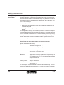
Designation:
IBS SYS PCP G4 UM E
Revision:
B
Order No.:
27 45 16 9
This manual is valid for:
PCP Software
Version 4.0
Firmware
Version ≥ 4.0
© Phoenix Contact 05/1997
5334B
Please Observe the Following:
In order to guarantee the safe use of your device in every situation, we
specify that you carefully read the manual. The following notes give you information on how to use this manual.
Requirements on the User Group
The use of products described in this manual is oriented exclusively to
qualified application programmers and software engineers familiar with automation safety concepts and applicable national standards. Phoenix Contact assumes no liability for erroneous handling or damage to products
from Phoenix Contact or external products resulting from disregard of information contained in this manual.
Explanations of Symbols Used
The attention symbol refers to erroneous handling which could lead to
damage to the hardware or software, or to personal injury. Personal injury
is understood to be any bodily harm in indirect connection with dangerous
process peripherals. The symbol is always located to the left of the tagged
text.
Text marked in this way informs you of system-related conditions that must
absolutely be observed to achieve error-free operation. In addition, the
hand symbol gives you tips and advice on the efficient use of hardware and
software optimization.
The text symbol refers to detailed sources of information (manuals, data
sheets, literature, etc.) on the subject matter, product, etc. This text also
provides helpful information for the orientation in the manual.
5334B
INTERBUS
We are Interested in Your Opinion
We are constantly attempting to improve the quality of our manuals.
Should you have any suggestions or recommendations for improvement of
the contents and layout of our manuals, we would appreciate it if you would
send us your comments. Please use the universal telefax form at the end
of the manual for this.
Statement of Legal Authority
This manual, including all illustrations contained herein, is copyright protected. Use of this manual by any third party in departure from the copyright
provision is forbidden. The reproduction, translation, or electronic or photographic archiving or alteration requires the express written consent of
Phoenix Contact. Violations are liable for damages.
Phoenix Contact reserves the right to make any technical changes that
serve for the purpose of technical progress.
Phoenix Contact reserves all rights in the case of patent award or listing of
a registered design. External products are always named without reference
to patent rights. The existence of such rights shall not be excluded.
5334B
Contents
1 Data Transmission within the Sensor/Actuator Area.........................................1-3
1.1 Bus Access Methods..................................................................... 1-4
1.2 Topology ....................................................................................... 1-5
1.3 INTERBUS Data Types................................................................. 1-6
1.4 Process Data Channel and Parameter Data Channel .................. 1-7
1.5 Communication Interface .............................................................. 1-8
1.6 INTERBUS Transmission Protocol ............................................... 1-9
2 Communication between INTERBUS Devices..................................................2-3
2.1 Application Example...................................................................... 2-3
2.2 Call/Response Method.................................................................. 2-6
2.3 Exchange of Device Parameters................................................... 2-9
2.4 Communication Services ............................................................ 2-12
3 Starting up Communication...............................................................................3-3
3.1 Information on the Application Example........................................ 3-5
3.2 Flowchart....................................................................................... 3-9
3.3 Establishing a Connection........................................................... 3-10
3.4 Exchanging Parameter Data ....................................................... 3-20
3.5 Aborting the Connection.............................................................. 3-28
3.6 Changing Default Communication
References 3-29
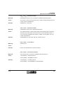
4 Communication Error Messages.......................................................................4-3
4.1 Error Messages of the Abort Service after Connection Abort ....... 4-4
4.2 Error Messages of the Reject Service......................................... 4-10
4.3 Descriptions of Service-Specific Error Messages ....................... 4-13
5334B
v
INTERBUS
Contents
5 PCP Operation with IBS CMD SWT G4 Software.............................................5-3
6 Description of Communication Services ...........................................................6-3
6.1 Overview of PCP Services ............................................................ 6-3
6.2 PCP Services with All Four Service Primitives.............................. 6-6
6.3 Domain Management.................................................................. 6-52
6.4 Services with Automatic Response............................................. 6-94
6.5 Unconfirmed Services ............................................................... 6-104
6.6 Service Rejection with the Reject Service................................. 6-109
6.7 PNM7 Services ......................................................................... 6-111
vi
5334B
Section 1
This section provides information on
– INTERBUS data types
– INTERBUS transmission methods
Data Transmission within the Sensor/Actuator Area ............................................1-3
1.1 Bus Access Methods......................................................................1-4
1.2 Topology ........................................................................................1-5
1.3 INTERBUS Data Types..................................................................1-6
1.4 Process Data Channel and Parameter Data Channel ...................1-7
1.5 Communication Interface ...............................................................1-8
1.6 INTERBUS Transmission Protocol ................................................1-9
5334B
1-1
INTERBUS
1-2
5334B
INTERBUS
Data Transmission within the Sensor/Actuator Area
1 Data Transmission within the Sensor/Actuator
Area
With augmenting automation the number of sensors and actuators is increasing at the same time as manufacturing processes are becoming more
and more complex. Using conventional parallel wiring for a complex control
process, pushes the costs for cables, installation, startup, and service up.
Thus, an up-to-date control concept requires the following:
– an economic solution with bus systems that allow serial data transmission and reduce overall costs of parallel wiring,
– an open and non-proprietary networking concept that can easily be
linked to already existing control systems, as well as
– flexibility with regard to future changes or extensions.
INTERBUS meets all of these requirements. This fieldbus was especially
designed for signal transmission within the sensor/actuator area.
5334B
1-3
INTERBUS
Data Transmission within the Sensor/Actuator Area
1.1 Bus Access Methods
Master/slave
method
INTERBUS uses the master/slave method for data transmission.
Master
The master is the device in the network that actively coordinates and controls the bus access. It transmits data to all devices and receives data from
all devices. In addition, the master is the interface to all higher control levels. It is called controller board.
Slaves
Slaves are various devices connected to the master via the bus. As all
slaves have equal rights, questions of priority do not arise.
1-4
5334B
INTERBUS
Topology
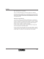
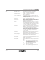
1.2 Topology
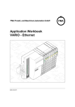
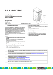
Ring topology
All devices – master and slaves – are connected in a ring topology. The ring
is formed with several lines within a cable.
PLC
INTERBUS
IBS BA DSC/I-T
Ord.No.: 27 23 04 2
Byte n
0
.
.
.
.
.
.
7
0
.
.
.
.
.
.
7
CLAB
Controller board
REMOTE
RS 232
Master
Slaves
5067B101
Figure 1-1 INTERBUS ring topology
5334B
1-5
INTERBUS
Data Transmission within the Sensor/Actuator Area
1.3 INTERBUS Data Types
Process data
Various I/O devices are used within the sensor/actuator area. Among these
are simple devices such as valves and switches processing only a few bits
of information. The information provided is process data that is, for example, state information on motor speed, switch settings, etc. Process data is
highly dynamic, i.e., it changes continuously and must always be updated.
Process data is time-critical and must be transmitted quickly and cyclically
between the sensors/actuators and controlling units. Transmission is equidistant, i.e. there are always the same time intervals. The information content of process data comprises only a few bits, e.g. the information 1 or 0
of a valve.
Parameter data
In addition, there are intelligent devices, e.g., frequency inverters, operating and indicating elements or controllers. Aside from process data, these
devices exchange larger data quantities with the higher-level control system. This data is parameter data which, for example, is used when starting
up machines and systems, when converting production facilities or in the
case of errors. In contrast to process data, parameter data seldom
changes, i.e., it is less dynamic and must seldom be updated. Parameter
data is cyclical data, to be transmitted only if required. As parameter data
does not directly influence the inputs and outputs and is rarely subjected to
change, the requirements made on the transmission rate of parameter data
are lower than in the case of process data. The information content of parameter data in the sensor/actuator area ranges between a few and some
hundred bytes per data record.
1-6
5334B
INTERBUS
Process Data Channel and Parameter Data Channel
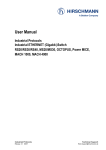
1.4 Process Data Channel and Parameter Data
Channel
Process data and parameter data is transmitted in the INTERBUS system
via two independent data transmission channels, i.e., the process data
channel and the parameter data channel. This additionally optimizes the
data transmission. Depending on the function, it is not required that every
device supports both channels. However, intelligent devices such as frequency inverters which transmit both process data and parameter data do
require both channels.
Process data
channel
The process data channel allows to access cyclically transmitted process
data. The application program is provided with an image of the current inputs. The application program, in turn, stores the output data that is transmitted to the outputs via the process data channel. With this direct memory
access, it is possible to avoid complex service access procedures.
Parameter data
channel
The parameter data channel transmits data if necessary. The parameter
data channel is integrated into the transmission protocol.
Additional services, i.e. network management services, are required for the
non-proprietary configuration, maintenance, and startup of the INTERBUS
system.
Application program
Process
data
channel
Parameter
data
channel
Network
management
5067A102
Figure 1-2 Process data channel and parameter data channel
5334B
1-7
INTERBUS
Data Transmission within the Sensor/Actuator Area
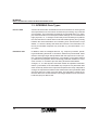
1.5 Communication Interface
Communication
services for data
exchange
To enable intelligent devices of an INTERBUS system to communicate with
each other, it is required to determine the way in which data is transmitted.
In factory automation, the "Manufacturing Message Specification (MMS)"
ISO standard has gained general acceptance. MMS provides an exactly
defined set of communication services used for handling administrative
tasks, identification and status inquiries, communication-related activities
and productive data transmission.
MMS was designed for networks which, with regard to hierarchy, are located above the INTERBUS level. In the sensor/actuator area, however,
there are other requirements in the foreground, e.g. short cycle times. Also,
when compared to higher levels, the requirements are reduced. For
INTERBUS, the MMS scope has been reduced to relevant services in compliance with these requirements. However, the basic structure has not
been affected.
PMS services for the
sensor/actuator area
The "Peripherals Message Specification (PMS)" is tailored to the sensor/
actuator area. PMS is a user interface according to the international MMS
model located at layer 7 of the OSI reference model. The PMS communication services allow to access parameter data.
Open
communication
The standardized PMS communication services ensure that the same
communication interface is used for all devices. In this way, devices of different manufacturers can be operated within one network and open communication is possible. The specification of a subset of the functional range
- e.g. for an application area that does not need all services - is referred to
as a communication profile.
1-8
5334B
INTERBUS
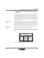
INTERBUS Transmission Protocol
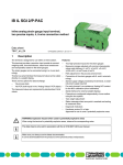
1.6 INTERBUS Transmission Protocol
Summation frame
method
In the INTERBUS system, all physical system devices are considered to be
only one logical device. With every cycle, the entire information of process
data is transmitted simultaneously to all devices within one summation
frame. Owing to the transmission position of individual information units
within the summation frame, every device can recognize its data and accept it.
Summation frame
Loop
check
Device 1
Device 2
Device n
FCS
Control
Control data
User data
5067A103
Figure 1-3 Summation frame protocol
Full-duplex
operation
5334B
The ring topology of the INTERBUS system allows full-duplex operation,
that means it is possible to transmit and receive data at the same time. With
this operation method, the transmission capacity is doubled and data transmission is very efficient.
1-9
INTERBUS
Data Transmission within the Sensor/Actuator Area
Master
Slave 1
Slave 2
Slave 3
Slave 4
Process
image
5067A104
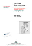
Figure 1-4 Structure of an INTERBUS system
Hybrid
transmission
method
However, not only process data but also parameter data must be transmitted via the summation frame. If, in the configuration phase, the frame
length is set to the maximum information of parameter data to be transmitted, the frame will not be fully utilized in most of the cycles. In addition, the
transmission time will increase by decreasing the efficiency of the system
at the same time. The summation frame method has therefore been modified for INTERBUS: gaps are left at those positions where devices exchanging data are addressed. If parameter data is to be transmitted, the
parameter block will be decomposed into individual segments that are as
long as the gap. The following segment lengths are available: 1 word, 2
words, and 4 words. One of these segments will be transmitted with every
cycle until the total parameter block has been transmitted. The segments
of data are then rejoined at the receiving end.
The simultaneous transmission of both process data and parameter data
is referred to as a hybrid transmission method.
1-10
5334B
INTERBUS
INTERBUS Transmission Protocol
Summation frame
Loop
check
ProDa
D1
ProDa
D2
ProDa ParaDa
D3
ParaDa
Dn
ProDa
D n+1
FCS
D
= Device
ProDa = Process data
ParaDa = Parameter data
= Control data
Control
5067A105
Figure 1-5 Hybrid transmission method
Peripherals
Communication
Protocol (PCP)
In INTERBUS, the "Peripherals Communication Protocol (PCP)" is responsible for decomposing parameter data into individual segments and composing it after transmission. The PCP protocol software supplies the services required for connection establishment and abort as well as for data
transfer. The PMS includes the formal description of these services. In this
way, both data types can be transmitted in parallel without affecting each
other.
Section 1 deals with the communication via the parameter data channel.
Section 2 explains terms that are required to understand PCP communication.
Section 3 shows how PCP communication is carried out with all commands
and parameters required.
Section 4 gives a systematic overview of error messages, error causes and
measures for error elimination.
Section 5 describes the IBS CMD SWT parameterization and diagnostic
software tool used for communication.
Section 6 lists all services with their corresponding parameters.
5334B
1-11
INTERBUS
Data Transmission within the Sensor/Actuator Area
1-12
5334B
Section 2
This section provides information on
– different device parameters
– basic terms of PCP communication
– tasks of communication services
Communication between INTERBUS Devices .....................................................2-3
2.1 Application Example.......................................................................2-3
2.1.1 Process Data Descriptions..................................................2-4
2.1.2 Object Description...............................................................2-5
2.2 Call/Response Method...................................................................2-6
2.2.1 Service Primitives ...............................................................2-7
2.2.2 Confirmed/Unconfirmed Services .......................................2-7
2.3 Exchange of Device Parameters....................................................2-9
2.4 Communication Services .............................................................2-12
2.4.3 Overview of PMS Services ...............................................2-12
2.4.4 Systematics of Supported User Services..........................2-14
2.4.5 Adaptation of Supported Services ....................................2-17
5334B
2-1
INTERBUS
2-2
5334B
INTERBUS
Communication between INTERBUS Devices
2 Communication between INTERBUS Devices
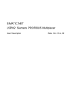
2.1 Application Example
To clarify the basic terms used in communication, let us assume the following real PCP application:
Together with other field devices, a frequency inverter (FI) is connected to
a PLC via a controller board. The characteristics of the devices are standardized according to the DRIVECOM Power Transmission Profile (Profile
No. 21).
PLC
INTERBUS
IBS BA DSC/I-T
Ord.No.: 27 23 04 2
Byte n
0
.
.
.
.
.
.
7
0
.
.
.
.
.
.
7
CLAB
Controller board
Master
REMOTE
RS 232
Slaves
Frequency inverter
5067B201
Figure 2-1 Application example
5334B
2-3
INTERBUS
Communication between INTERBUS Devices
Device parameters
Device parameters are data of intelligent field devices (PCP devices) that
are required within the startup phase of machines and systems. After they
have been entered once, they only need to be modified in the case of reparameterization or error. The parameters are pre-configured and can be
taken from the device manufacturer’s documents.
Parameters of a
frequency inverter
As an electrical drive controller, a frequency inverter is characterized by the
fact that changes of a process variable (rotational speed, position, and moment) are caused by analog or digital signals. To adapt the drive controller
and the motor to the process in an optimum way, additional information is
required. Aside from the setpoint information, the frequency inverter requires information on motor parameters, admissible minimum and maximum rotational speed, maximum rotational speed change during acceleration and deceleration, starting ramp, starting current, etc.
All of this additional information forms the device-specific parameters that
can be changed via the parameter data channel. The following explanations exclusively refer to these device parameters. Parameters of process
variables are not taken into account.
2.1.1 Process Data Descriptions
The parameter values of all PCP devices are used for communication via
the parameter data channel - they are the process data descriptions. Each
parameter has a number, the index, to distinguish individual parameters
during communication.
Object dictionary
(OD)
The object dictionary (OD) - a standardized list - includes the index together with the description of parameter characteristics. Each PCP device
that exchanges information via the parameter data channel has its own object dictionary.
Index
The index is the address of the communication object. It is required to identify the object. Other PCP devices can address the communication object
at this address.
2-4
5334B
INTERBUS
Object Description
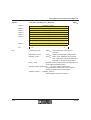
Table 2-1 Object description (example)
Object description (OD)
Index
Type
Object
Name
...
...
...
...
60 4Ahex
Ramp
Record
Speed quick stop
60 4Bhex
Integer16
Array
Setpoint factor
...
...
...
...
2.1.2 Object Description
The object description includes all characteristics of the object such as data
type, object type, names, etc.
Object types
A difference is made between various object types:
Simple variable
– Objects of the simple variable type.
Examples: measured values, time or status of a device.
Array
– Objects of the array type, i.e., several similar objects of the simple variable type that are combined to one object. Each element can be individually accessed.
Example: a series of similar measured values.
Record
– Objects of the record type, i.e., several different objects of the simple
variable type that are combined to one object. Just like the array type,
each element of a record can be individually accessed.
Example: combination of data within a measuring protocol that includes
the measured value as well as additional information, e.g., the time of
measurement.
Program invocation
– Objects of the program invocation type, i.e., executable program sequences.
5334B
2-5
INTERBUS
Communication between INTERBUS Devices
2.2 Call/Response Method
Access to device
parameters
Device parameters are accessed via a call/response method: A device
sends a request to another device. The device requesting this service is the
client. The device that carries out the request is the service provider, the
server.
Application
processes
Both client and server are application processes that run on respective devices. Application processes are all activities of a PCP device within the
system, except for the real tasks such as controlling a motor.
Client/server model
With INTERBUS, the master and the slaves can carry out functions of both
client and server.
Service request
Client
Service response
Server
5067A203
Figure 2-2 Client/server model
Based on our example, one task (application process A) of the automation
device could be to transmit parameters (e.g. speed acceleration) to the frequency inverter. The frequency inverter receives the new speed acceleration and converts it correspondingly (application process B).
Communication
services
The client and server use communication services for service request and
execution.
If, in our example, the parameter value for the speed acceleration is to be
transmitted to the frequency inverter, a write command must be used, i.e.,
the Write_Service.
2-6
5334B
INTERBUS
Service Primitives
2.2.1 Service Primitives
(Service)
Primitives
A service is divided into individual primitives (basic operations of the service).
INDICATION
REQUEST
Client
Request message
Response message
CONFIRMATION
Server
Service
execution
RESPONSE
5067A204
Figure 2-3 PCP primitives (confirmed services)
Request
First, the client sends a service request to the server. In the application example, the automation device requests, for example, to transmit a parameter value to the frequency inverter.
Indication
This request is indicated to the server as a service input. In the application
example, the input of a parameter value is indicated to the frequency inverter.
Response
The server executes the service. Afterwards, it sends a service response
to the client. In the application example, the frequency inverter is responsible for the new parameter setting. It sends a response that it received the
parameter value and carried out the new setting.
Confirmation
The service execution is indicated to the client as a service confirmation. In
the application example, the parameter transmission to the frequency inverter is confirmed to the automation device.
The bus transmits the information content in the form of a message (PDU =
Protocol Data Unit).
2.2.2 Confirmed/Unconfirmed Services
A call/response method in compliance with the above model is referred to
as a confirmed service. In addition, there are unconfirmed services where
the service request is executed but a confirmation will not be returned.
An example of an unconfirmed service that is transmitted from the client to
the server is a connection abort. An example of an unconfirmed service initiated by the server, i.e. in the opposite direction, is the information report.
5334B
2-7
INTERBUS
Communication between INTERBUS Devices
ABORT_
REQUEST
Client
ABORT_
INDICATION
Request message
Server
Service
execution
5067A205
Figure 2-4 Unconfirmed services
Invoke_ID
In the case of confirmed services, the service request and the respective
service confirmation are provided with a reference code, the Invoke_ID.
Access protection
The manufacturer can provide access protection for data that should only
be available to determined devices, i.e., access rights to communication
objects are limited for certain devices. Access protection can be realized
by defining
– access groups. Not all of them are allowed to access certain communication objects.
– passwords. A device can only access a communication object with the
password defined for this communication object.
Additionally, services can be differentiated within access protection, e.g.
general read access for all devices, but write access only for a determined
group.
Information about whether and in which form access protection exists for a
communication object is stored in the object description.
2-8
5334B
INTERBUS
Exchange of Device Parameters
2.3 Exchange of Device Parameters
Communication
relationships
To exchange data between two INTERBUS PCP devices, it is required to
establish a logical connection between them first. Logical connections of
this type are called communication relationships. Communication relationships are established between application processes.
Communication
relationship list
(CRL)
The controller board generates a list for every PCP device specifying all
permitted communication relationships independent of their time of use.
This communication relationship list (CRL) stores the connection type as
well as context conditions - the connection parameters - by which the communication relationship can be established. The CRL can manually be
changed if required.
The logical connections configured in the communication relationship list
allow a smooth data exchange between two communication devices. Before information is exchanged, the connection parameters (context conditions) of both communication partners are checked for consistency during
connection establishment.
Communication
reference number
(CR)
5334B
The communication relationship list is divided into several lines. Every permissible communication relationship has a number, the communication reference number (CR). Thus, the communication relationship is clearly
coded. A clear code is required to distinguish the individual devices. The
INTERBUS controller board automatically numbers the devices when initializing the INTERBUS system. According to the physical bus configuration, it assigns the numbers beginning with two.
2-9
INTERBUS
Communication between INTERBUS Devices
Controller board
Application process
Master
CRL
CR = 2
CR = 3
CR = 4
Module 1
Application process
Slave
CRL
CR = 2
V.24
CRL
Application process
Slave
CR = 3
Frequency inverter
CRL
Application process
Slave
CR = 4
5067A206
Figure 2-5 Relationship between CRL, CR, and application process
2-10
5334B
INTERBUS
Exchange of Device Parameters
In addition to the CR, each CRL line contains complete details of the connection parameters.
Table 2-2 CR connection parameters
Connection parameters
CR
Size of the
send buffer
Low-Prio
Size of the
receive buffer
Low-Prio
Supported
PMS services
Some attributes of the CRL entry are not supported by INTERBUS. They
are only provided for reasons of compatibility to Profibus and are assigned
standard values. The system automatically enters the CR during initialization.
CR: For the local application process, the communication reference is a
clear identification for the communication relationship.
Size of the send buffer Low-Prio: This attribute contains the maximum
possible length of the PDU in transmitting direction with low-priority that
can be processed in this communication relationship.
Size of the receive buffer Low-Prio: This attribute contains the maximum
possible length of the PDU in receiving direction with low-priority that can
be processed in this communication relationship.
Supported PMS services: This attribute informs about which services are
supported in this communication relationship.
5334B
2-11
INTERBUS
Communication between INTERBUS Devices
2.4 Communication Services
The Peripherals Communication Protocol (PCP) offers the user several
standardized PMS services that can be divided into three groups:
– User services
– Administration services
– Management services
Section 6 describes the PMS services in detail. The application example is
continued in Section 3. The handling of the PMS services and check mechanisms of the Peripherals Communication Protocol are initiated through the
"Initiate" service.
2.4.3 Overview of PMS Services
User services
2-12
An application process accesses the communication objects via the user
services. The user services comprise the following PMS services:
– Start
Starting a program (after a reset)
on a PCP device.
– Stop
Stopping a program.
– Reset
Resetting a program.
– Resume
Restarting a program after a stop.
– Write
Setting variables (device parameters)
of a PCP device.
– Read
Reading variables (device parameters)
of a PCP device.
– Information_Report
Unconfirmed transmission of a parameter.
– Download Services
Data transfer from the client to the server
Services:
"Initiate_Download_Sequence", "Download_
Segment", and "Terminate_Download_
Sequence".
– Upload Services
Data transfer from the server to the client.
Services:
"Initiate_Upload_Sequence", "Upload_Segment", and "Terminate_Upload_Sequence".
5334B
INTERBUS
Overview of PMS Services
– Request_Domain_Upload
Requesting the automatic data transfer from the
server to the client.
– Read_ / Write_With_Name
Reading/Writing an object that is not explicitly
described in the PMS object dictionary.
Administration
services
Management
services
5334B
Administration services are used to exchange information via communication objects. The administration services comprise the following PMS services:
– Status
Reading the device status (operating state)/
application state (communication state).
– Identify
Reading the manufacturer’s name, type, version.
– Get_OD
Reading the object description.
The management services allow and secure the operation of the communication system. These services include the establishment and abort of a
connection.
– Initiate
Establishing a connection.
– Abort
Aborting a connection.
– Reject
Rejecting an inadmissible service.
2-13
INTERBUS
Communication between INTERBUS Devices
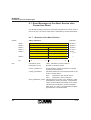
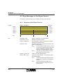
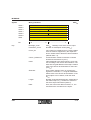
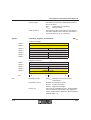
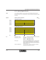
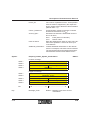
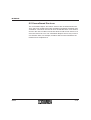
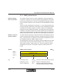
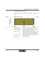
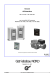
2.4.4 Systematics of Supported User Services
Representation
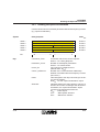
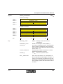
The supported user services of a PCP device are represented within a bit
pattern of 48 bits in hexadecimal notation. The bits 0 ... 23 indicate the supported services as a client, bits 24 ... 47 as a server. Of these 48 bits, only
some are actually used.
Bits 3, 4, 8, 27, 28, and 32 represent several services.
All unused bits, as well as the bits of the unsupported services are set to
"0". If the service is supported, the bits used are set to "1".
Get_OD
Initiate_Download_Sequence
Download_Segment
Terminate_Download_Sequence
Initiate_Upload_Sequence
Upload_Segment
Terminate_Upload_Sequence
Request_Domain_Upload
Start
Stop
Reset
Resume
Read
Write
Information_Report
Write_With_Name
Read_With_Name
0
3
4
6
8
10 11
0 0 0 0 0 0 0 0
0 0 1 1 0 0 0 0
1. Byte
2. Byte
24
27 28
30
32
34 35
1 0 0 1 1 0 1 0
1 0 1 1 0 0 0 0
4. Byte
5. Byte
16
23 Bit
0 0 0 0 0 0 0 0 as a client
3. Byte
40
default = 00 30 00hex
47 Bit
1 0 0 0 0 0 0 1 as a server
6. Byte
default = 9A B0 81hex
5334A301
Figure 2-6 Systematics of the supported user services
Example
2-14
In the application example, the controller board supports the services
"Get_OD", "Read", and "Write" as a client and all services as a server.
5334B
INTERBUS
Systematics of Supported User Services
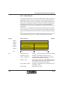
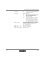
Thus, the bit pattern is as follows:
0
6
15 16
8
1 0 0 0 0 0 0 0
80hex
0 0 1 1 0 0 0 0
30hex
1. Byte
2. Byte
24
27 28
30
32
23 Bit
0 0 0 0 0 0 0 0
Client
00hex
3. Byte
34 35
40
1 0 0 1 1 0 1 0
9Ahex
1 0 1 1 0 0 0 0
B0hex
4. Byte
5. Byte
47 Bit
1 0 0 0 0 0 0 1
Server
81hex
6. Byte
5067B306
Figure 2-7 Bit pattern of the supported services of the controller board
Entry in the CRL
In the CRL, each of these 8-bit patterns is represented in hexadecimal notation. In the application example, the entry for the supported services in
the CRL of the controller board is called "frequency inverter":
...
5334B
|
80 30hex
|
00 9Ahex |
B0 81hex
2-15
Key
—
—
—
—
—
—
X
X
X
—
—
—
—
—
—
X
X The service is supported.
— The service is not supported.
—
—
—
—
—
—
X
X
X
—
—
—
—
—
—
X
—
—
X
—
—
X
—
—
X
—
—
—
—
—
—
X
Request_Domain_Upload
Write_With_Name
Read_With_Name
Terminate_Upload_Sequence
Upload_Segment
—
—
—
—
—
—
—
—
X
X
X
X
X
X
X
X
Initiate_Upload_Sequence
—
—
—
—
—
—
—
—
X
X
X
—
X
—
X
X
Terminate_Download_Sequence
—
X
X
—
X
X
X
—
—
—
X
—
—
X
X
X
Download_Segment
Get_OD
—
X
X
—
X
X
X
—
—
—
X
—
—
X
X
X
Initiate_Download_Sequence
Information_Report
Resume
Reset
Write
—
—
—
X
X
X
—
X
X
—
—
X
X
X
X
X
Read
00 00 00
00 30 00
00 30 01
00 80 00
00 B0 00
00 B0 01
18 30 00
18 80 00
18 80 81
80 00 80
80 30 80
80 80 00
80 80 80
80 B0 00
80 B0 80
9A B0 81
Stop
Coding
[hex]
Start
INTERBUS
Communication between INTERBUS Devices
—
—
—
—
—
—
—
—
—
—
—
—
—
—
—
X
5334A302
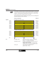
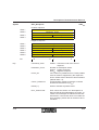
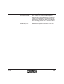
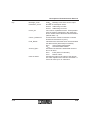
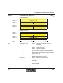
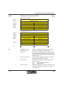
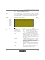
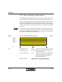
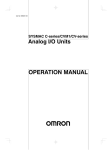
Figure 2-8 Combination options of the services
Figure 2-8 lists the most frequently used combination options of the services in hexadecimal notation. If one of these combinations is in the first
three bytes, it is possible to read the client services. If a combination is between byte 4 and 6, it is possible to read the server services.
2-16
5334B
INTERBUS
Adaptation of Supported Services
2.4.5 Adaptation of Supported Services
All services that can be processed by the controller board and the PCP device as both client and server have to be compared and adapted.
As a client the PCP device must not support more services than the server
communication partner.
However, as a server a device can support more services than the client
communication partner.
5334B
2-17
INTERBUS
Communication between INTERBUS Devices
2-18
5334B
Section 3
This section provides information on the
– step-by-step PCP communication startup using an example
Starting up Communication ..................................................................................3-3
3.1 Information on the Application Example.........................................3-5
3.2 Flowchart........................................................................................3-9
3.3 Establishing a Connection............................................................3-10
3.3.1 Initiate_Request Service Request.....................................3-11
3.3.2 Initiate_Confirmation Service Confirmation.......................3-12
3.3.3 Changing the Buffer Size of the Controller Board.............3-17
3.3.4 Adapting the Controller Board and Frequency Inverter ....3-19
3.4 Exchanging Parameter Data ........................................................3-20
3.4.1 Reading the Speed Acceleration ......................................3-21
3.4.2 Changing the Speed Acceleration ....................................3-24
3.5 Aborting the Connection...............................................................3-28
3.6 Changing Default Communication References ............................3-29
5334B
3-1
INTERBUS
3-2
5334B
INTERBUS
Starting up Communication
3 Starting up Communication
There are several ways to start up communication:
– For some controller boards, there are pre-written function blocks by
which the services can be called. For all other controller boards, the required service calls are to be integrated into the application program.
– The IBS CMD SWT G4 software tool from Phoenix Contact. This tool
can be used for all Generation 4 host systems. It is the simplest way to
establish and test a communication connection via command codes.
Independent of the tools used, this section describes the systematics of
communication by means of service primitives. In Section 5, there is a description of how communication can be easily carried out with the
IBS CMD SWT G4 software.
Communication
phases
INTERBUS supports connection-oriented (1 - 1) communication relationships. The connection-oriented communication is divided into three
phases:
– Connection establishment
– Data transfer
– Connection abort
Connection establishment phase
In the connection establishment phase, a PCP device functioning as a
client tries to establish a communication connection to a PCP device functioning as a server. During process, the context conditions - the connection
parameters - that are determined in the communication relationship lists of
both devices are checked. If the context conditions correspond to each
other, the data transfer phase will be initiated. Otherwise, the connection
establishment will be aborted with an error message.
5334B
3-3
INTERBUS
Starting up Communication
Connection establishment request
under context conditions
Server
Client
Context establishment request
under context conditions accepted
5067A301
Figure 3-1 Connection establishment phase
Client
Information exchange under
agreed conditions
Server
5067A302
Figure 3-2 Data transfer phase
During the data transfer phase, the PCP devices exchange data under context conditions. The connection continues to exist until it is intentionally
aborted or a communication error occurs.
Connection abort phase
After the data exchange has been completed, the connection can be terminated by a connection abort. In the case of a communication error, the connection would be automatically aborted. Thereafter, the data exchange can
only be carried out after a renewed connection establishment.
Connection establishment
or
Client
Connection abort
Server
Error
5067A303
Figure 3-3 Connection abort phase
3-4
5334B
INTERBUS
Information on the Application Example
3.1 Information on the Application Example
In our application example, a frequency converter is to be parameterized.
Before a parameter can be transmitted, a connection between the controller board and the frequency inverter has to be established. This step is initiated by the application process of the controller board functioning as a
client.
Example
configuration
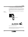
Communication startup is illustrated on the basis of a very simplified bus
configuration.
PLC
INTERBUS
IBS BA DSC/I-T
Ord.No.: 27 23 04 2
Byte n
0
.
.
.
.
.
.
7
0
.
.
.
.
.
.
7
CLAB
Controller board
REMOTE
RS 232
Master
BK module
I/O module V.24 module Frequency inverter
5067B304
Figure 3-4 Bus configuration example
There are four devices connected to the bus. The third and fourth device
are communication modules: a V.24 module and a frequency inverter. The
services are transmitted and received via a PLC.
5334B
3-5
INTERBUS
Starting up Communication
Changing the speed
acceleration
In the application example, the set parameter value is to be modified for the
speed acceleration of the frequency inverter. The speed acceleration parameter indicates the slope of the starting ramp. The parameter consists of
the quotient of the two subparameters "delta speed" and "delta time" and
is to be set to 100 rpm.
The data type is "Record":
– an Unsigned 32 data type (4 bytes delta speed, value between 0 and
4 295 967 295) and
– an Unsigned 16 data type (2 bytes delta time, value between 0 and
65 535).
In the application example, the frequency inverter is a device corresponding to the DRIVECOM Power Transmission Profile 21. The parameters that
can be accessed are described in an object dictionary that was preconfigured by the manufacturer and does not need any further processing.
Please refer to the device documentation for the required information on
the individual objects.
Example:
Extract from the device description of a frequency inverter
Speed acceleration (60 48 hex)
Data format:
Ramp structure (index 21hex)
Subindex 1: Unsigned 32
Numerator, delta speed in rpm
Subindex 2: Unsigned 16
Denominator, delta time in sec
Meaning:
Startup time referred to delta speed. The parameter is
mapped to the starting ramp via the ramp-min frequency inverter function (L-C12). If the denominator is 0, the
ramp is switched off.
Factory setting:
Ramp is switched off.
Numerator = 0
Denominator = 0
In our example, only the controller board has client functionality. All other
devices are dedicated server devices. As a client, they cannot access ob-
3-6
5334B
INTERBUS
Information on the Application Example
jects of the controller board or other PCP devices. In the example, the controller board initializes all of the described communication activities.
During startup of the controller board a default CRL is automatically created. In this CRL, the context conditions for the data transfer - the connection parameters - with the other PCP devices are determined. In our example, the following CRL is assumed:
Example CRL of a
controller board
02hex
...
02hex
...
40hex
40hex
8030hex
080hex
B080hex
...
03hex
...
40hex
40hex
8030hex
0080hex
B080hex
(Number of entries)
[Reserved area]
(CR: communication relationship to the V.24 module)
(Maximum length of a PDU in transmitting direction: 64 bytes)
(Maximum length of a PDU in receiving direction: 64 bytes)
(Supported services: as a client, Get_OD,
Read and Write are supported; as a server, Get_OD,
Start, Stop, Read, Write, Information_Report)
(CR: Communication relationship to the frequency inverter)
(Maximum length of a PDU in transmitting direction: 64 bytes)
(Maximum length of a PDU in receiving direction: 64 bytes)
(Supported services: as a client, Get_OD,
Read and Write are supported; as a server, Get_OD,
Start, Stop, Read, Write, Information_Report)
The manufacturer preconfigures the CRL of the frequency inverter.
CRL of the frequency
inverter
01hex
...
02hex
...
64hex
64hex
0000hex
0000hex
3000hex
(Number of entries)
[Reserved area]
(CR: communication connection to the controller board)
(Maximum length of a PDU in transmitting direction: 100
bytes)
(Maximum length of a PDU in receiving direction: 100 bytes)
(Supported services:
as a client, no service;
as a server, Read and Write)
At first, the CRLs are not visible. If there are discrepancies between the
CRLs, an error message is indicated during connection establishment.
5334B
3-7
INTERBUS
Starting up Communication
Section 3.3.2 "Initiate_Confirmation Service Confirmation" explains how
these discrepancies can be eliminated.
Sequence
To allow the speed acceleration parameter to be changed,
1. initialize the INTERBUS system.
2. start data transmission (Start Data Transfer).
3. establish the connection with the Initiate_Request command. If an error
message is indicated (Initiate_Confirmation negative), the error must
be removed with the Load_CRL_Attribute_Loc_Request command.
4. write the set value for the speed acceleration via the parameter data
channel. In order to show how parameter values of objects can be read
out, in our example, the preset value should first be read with a
Read_Request before the new value is written. In general, this must
not be carried out before a Write_Request.
5. abort the connection with the Abort_Request. This connection need
only be aborted when the controller board is switched off or before a
reset. Otherwise, an error message will be put out during the next connection establishment.
The flowchart schematically shows the procedure.
Section 3.6 includes a description of how the default communication references can be changed with the Load_CRL_Attribute_Loc_Request, as far
as this is required after a modification or extension of the system.
3-8
5334B
INTERBUS
Flowchart
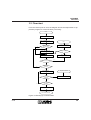
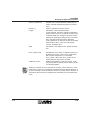
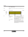
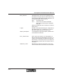
3.2 Flowchart
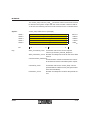
From the client’s point of view, the diagram shows the steps within an application program for communication processing:
Start
Initialize INTERBUS
Start INTERBUS cycle
No
End
Fatal error, evaluate
Abort parameter
Must the CRL
be changed ?
Yes
Yes
if retry_count > 2 ?
Load_CRL_Attributes
No
retry_count :=
retry_count + 1
Initiate_Request
An Abort occured?
Yes
No
No
Initiate_Conf.
positive?
Yes
Service request
Service conf.
positive?
Program correction
Evaluate error message
No
Yes
Yes
Further service
request?
No
Abort_Request
Connection aborted
Figure 3-5 Starting up communication
5334B
3-9
INTERBUS
Starting up Communication
3.3 Establishing a Connection
Before establishing a connection, use the "Initiate" service. In the service
request, it is required to indicate the communication reference number
(CR) of the application process of the communication partner, i.e. of the
server to be called.
After checking the reliability of the connection establishment, the server indicates the success or failure of the connection establishment with the service response Initiate_Response. Thus, the program takes two possibilities
into account:
1. The connection is established. For this, the "Initiate_Confirmation" with
positive result is provided.
2. The automatic test mechanisms detect that a connection establishment
is inadmissible, as the entries in the two CRLs do not correspond to
each other. For this, the "Initiate_Confirmation" with negative result is
provided. The negative message includes error codes that must be
evaluated.
3-10
5334B
INTERBUS
Initiate_Request Service Request
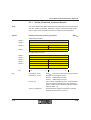
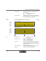
3.3.1 Initiate_Request Service Request
Syntax:
Initiate_Request
Word 1
Command_Code
00 8Bhex
Word 2
Parameter_Count
00 02hex
Word 3
—
Communication_Reference
00 03hex
Word 4
Password
Access_Groups
00 00hex
15 ...............................8
7.................................. 0
Bit
Key:
00 8Bhex
Command_Code:
Command code of the service request:
008Bhex for "Initiate_Request".
Parameter_Count:
Number of subsequent data words:
0002hex for two subsequent data words
(Communication_Reference and
Password | Access_Groups).
Communication_Reference:
Communication reference number of the communication relationship between controller board
and frequency inverter.
5334B
Password:
A password was defined for this communication
relationship to access device objects. Please refer to the device documentation for the password. There is no password required for
communication objects that are defined in the
DRIVECOM Power Transmission Profile 21.
Therefore, the value 00hex must be used.
Access_Groups:
The controller board is assigned to a determined
access group for which an access authorization
for objects of the frequency inverter is specified.
Please refer to the device documentation for the
Access_Groups value. For communication objects that are defined in the DRIVECOM Power
Transmission Profile 21, there is no access protection provided via access groups. Therefore,
the value 00hex must be used.
3-11
INTERBUS
Starting up Communication
3.3.2 Initiate_Confirmation Service Confirmation
After processing the service request "Initiate_Request", the system puts
out the service confirmation "Initiate_Confirmation". This message shows
whether the connection establishment was successful (positive message).
If the connection establishment was unsuccessful, a negative message will
be put out. A negative message is indicated by the Result parameter unequal to zero.
Syntax
Initiate_Confirmation
808Bhex
Positive message
Example:
Message_Code
Word 1
Word 2
Word 3
80 8Bhex
Parameter_Count
—
00 06hex
Communication_Reference
Word 4
Result (+)
00 00hex
Word 5
Version OD
00 00hex
Word 6
Profile
00 21hex
Word 7
Protection
Password
FF 00hex
Word 8
Access_Groups
—
00 00hex
Negative message
3-12
00 03hex
Example
Word 1
Message_Code
80 8Bhex
Word 2
Parameter_Count
00 08hex
Word 3
–
Communication_Reference
00 03hex
Word 4
Error_Class
Error_Code
00 xxhex
Word 5
Additional Code
Word 6
Send_Buffer_Size
Word 7
Receive_Buffer_Size
Word 8
Services_Supported (1)
Services_Supported (2)
Word 9
Services_Supported (3)
Services_Supported (4)
Word 10
Services_Supported (5)
Services_Supported (6)
Bit
15 ...............................8
7.................................. 0
00 00hex
5334B
INTERBUS
Initiate_Confirmation Service Confirmation
Key:
5334B
Message_Code:
Message code for service confirmation:
808Bhex for "Initiate_Confirmation".
Parameter_Count:
Number of subsequent parameters
(here: 6 data words).
Comm._Reference:
Communication reference number of the communication relationship between controller board
and frequency inverter.
Result (+):
0000hex indicates a positive result.
Version_OD:
Version number of the object directory. This parameter is device-specific and is read by the system from the object dictionary.
Profile:
Identification of the device profile, i.e., the number or the application-specific profile is indicated.
In this example, the Power Transmission Profile
21 is used, the value is therefore 0021hex.
Protection:
Includes the "Access_Protection_Supported" attribute from the device documentation of the frequency inverter. The parameter indicates
whether the access rights of the frequency inverter are checked during object access. As this
is the case in the example, the value FFhex
(= true) is shown.
Password:
Manufacturer-specific but generally not used. In
the example, the entry is therefore 00hex.
Access_Groups:
Manufacturer-specific but generally not used. In
the example, the entry is therefore 00hex.
Error_Class:
Contains the error message classification of the
"Initiate" service (00hex).
Error_Code:
There are three causes leading to an error message:
The send and receive buffers of the
01hex
controller board and the frequency inverter do not match in size.
The supported services of both
02hex
devices do not match.
The application program rejects the
04hex
3-13
INTERBUS
Starting up Communication
service; the error cause is manufacturer-specific. Please refer to the
device documentation. The device
may not be ready for operation.
Additional_Code:
Contains manufacturer-specific information on
the error cause (Error_Code = 04hex). For the error codes 01hex and 02hex (Error_Code), the parameter is always set to the value 0000hex.
Send_- / Receive_Buffer: The buffer sizes of the frequency inverter are indicated in the bits 7 ... 0 of the Send_Buffer and
Receive_Buffer parameters. Each buffer comprises 100 bytes (64hex). The bits 15 ... 8 are not
supported.
Services_Supported:
Coding of the supported services that can be
processed by the frequency inverter. The coding
is carried out with 6 bytes indicating which services are carried out by the device as a client (1st
to 3rd byte) and which as a server (4th to 6th
byte).
In the following, the causes for the error messages "Error_Code = 01hex"
and "Error_Code = 02hex", as well as their removal are described on the
basis of the application example.
Causes for the error code 01hex
Error cause
The "Error_Code = 01hex" error message means that the send and receive
buffer of the controller board and frequency inverter do not match.
Error removal
The send buffer of the controller board must be less than or equal to the
receive buffer of the device - in this case, the frequency inverter.
The receive buffer of the controller board must be greater than or equal to
the send buffer of the device.
3-14
5334B
INTERBUS
Initiate_Confirmation Service Confirmation
In our example, the send buffer of the controller board, with 64 bytes, is
smaller than the receive buffer of the frequency inverter, thus meeting the
requirements.
The receive buffer of the controller board is 64 bytes (40hex). It is smaller
than the send buffer of the frequency inverter with 100 bytes (64hex) and
has therefore caused the error message.
The surest way to avoid another error message is to set the values of both
buffer sizes of the controller board to the values of the device, in this case
to 100 bytes (64hex).
The "Load_CRL_Attribute_Loc" service allows to change the buffer sizes
of the CRL (see "Changing the Buffer Size of the Controller Board" on Page
3-17).
Causes for the error code 02hex
Error cause
The "Error_Code = 02hex" error message means that the supported services of the controller board and the device (here the frequency inverter)
do not match.
Error removal
The supported services must be adapted to each other. This process requires background information. First, it is required to become familiar with
the systematics of the coding and adaptation of the supported services
(Services_Supported parameter, see Section 2.4).
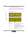
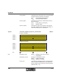
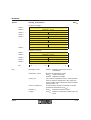
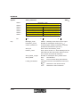
In the example, the controller board supports the services "Get_OD",
"Read" and "Write" as a client and all services as a server. The corresponding entry in the CRL is as follows:
Figure 3-6 Services of the controller board (example)
5334B
3-15
INTERBUS
Starting up Communication
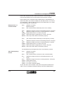
The services that can be processed by the controller board and the frequency inverter either as a client or as a server must be compared and
adapted to each other.
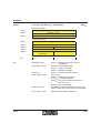
Service comparison of the frequency inverter and controller board
Table 3-1
Service comparison of the frequency inverter as a client and
the controller board as a server
Get_OD
Start, Stop,
Reset, Resume
Read
Write
Information_
report
–
–
–
–
–
Frequency inverter
Client
X
X
X
X
X
Controller board
Server
All of the supported services indicated in the client line must also be supported in the server line. In this case, there are no problems as the controller board supports all services as a server and the frequency inverter supports none as a client.
Table 3-2
Service comparison of the controller board as a client and the
frequency inverter as a server
Get_OD
Start, Stop,
Reset, Resume
Read
Write
Information_
Report
X
–
X
X
–
Controller board
Client
–
–
X
X
–
Frequency inverter
Server
The controller board supports the "Get_OD" service as a client but the frequency inverter does not support it as a server. This causes the error message.
To remove the error, the "Get_OD" service as a client must be switched off
on the controller board. To do this, use the "Load_CRL_Attribute_Loc" service (see "Adapting the Controller Board and Frequency Inverter" on Page
3-19).
3-16
5334B
INTERBUS
Initiate_Confirmation Service Confirmation
3.3.3 Changing the Buffer Size of the Controller Board
Syntax:
Load_CRL_Attribute_Loc_Request
Word 1
Command_Code
02 64hex
Word 2
Parameter_Count
00 04hex
Word 3
Attribute_Code
00 xxhex
Word 4
Entry_Count
00 01hex
Word 5
Communication_Reference
00 03hex
Word 6
Attribute_Value
00 64hex
Bit
Key:
02 64hex
15 ......................................................................... 0
Command_Code:
Command code for the service request:
0264hex "Load_CRL_Attribute_Loc_Request".
Parameter_Count:
Number of subsequent parameters
(here: 4 data words).
Attribute_Code:
Code for the parameter to be changed. Enter:
000Ehex for send buffer (Send_Buffer).
0010hex for receive buffer (Receive_Buffer).
Entry_Count:
Counter that indicates for how many devices a
new attribute must be set at the same time (here:
0001hex, as only the entry Communication_
Reference = 3 is to be changed.
Comm._Reference:
Communication reference of the device.
Attribute_Value:
Setting for the attribute selected with the Attribute_Code parameter. The attribute can consist
of several words (here: 0064hex for a send buffer
length of 100 bytes).
If the size of the receive buffer should be changed, enter the value 10hex for
the Attribute_Code parameter and the desired buffer value in the
Attribute_Value field.
It is possible to change the same attribute on several devices at the same
time. For this, set the value of the Entry_Count parameter to the corresponding number of devices and indicate the communication reference
and attributes for each device.
5334B
3-17
INTERBUS
Starting up Communication
After successful processing of the service request
"Load_CRL_Attribute_Loc_Request", the service confirmation
"Load_CRL_Attribute_Loc_Confirmation" will be returned.0
Load_CRL_Attribute_Loc_Confirmation
Syntax:
Positive message
Word 1
Message_Code
82 64hex
Word 2
Parameter_Count
00 01hex
Word 3
Result (+)
00 00hex
Bit
Key:
3-18
82 64hex
15 ...............................8
7.................................. 0
Message_Code:
Message code for the service confirmation:
82 64hex "Load_CRL_Attribute_Loc_
Confirmation".
Parameter_Count:
Number of subsequent parameters:
0001hex For 1 data word.
Result (+):
0000hex Indicates a positive result.
5334B
INTERBUS
Initiate_Confirmation Service Confirmation
3.3.4 Adapting the Controller Board and Frequency Inverter
The supported services of the frequency inverter can be found in the service confirmation "Initiate_Confirmation":
– 00 00 00hex: No services as a client.
– 00 30 00hex: "Read" and "Write" services as a server.
For services of the controller board, please refer to the example CRL on
Page 3-7:
– 80 30 00hex: "Get_OD", "Read" and "Write" services as a client.
– 9A B0 81hex: All services as a server.
The "Load_CRL_Attribute_ Loc" service allows to adapt the supported services of the controller board and frequency inverter.
Syntax:
Load_CRL_Attribute_Loc_Request
Word 1
Command_Code
02 64hex
Word 2
Parameter_Count
00 04hex
Word 3
Attribute_Code
00 12hex
Word 4
Entry_Count
00 01hex
Word 5
Communication_Reference
00 03hex
Word 6
Attribute_Value
00 80hex
Bit
Key:
5334B
02 64hex
15 ......................................................................... 0
Command_Code:
Command code for the service request:
0264hex.
Parameter_Count:
Number of subsequent parameters:
0004hex For 4 data words.
Attribute_Code:
Code for the parameter to be changed. Enter:
00 12hex For supported services.
Entry_Count:
Number of devices to be changed:
0001hex For 1 device.
Comm._Reference:
Communication reference of the device:
0003hex For the frequency inverter.
Attribute_Value:
Setting of the attribute selected in the
Attribute_Code parameter:
0080hex For the Get_OD_Long attribute.
3-19
INTERBUS
Starting up Communication
3.4 Exchanging Parameter Data
To explain how parameter data is exchanged, the example of the frequency inverter is used.
First, the speed acceleration is read out with the "Read" service
(see "Reading the Speed Acceleration" on Page 3-21).
Then, the speed acceleration is set to 100 rpm with the "Write" service (see
"Changing the Speed Acceleration" on Page 3-24).
3-20
5334B
INTERBUS
Reading the Speed Acceleration
3.4.1 Reading the Speed Acceleration
Use the "Read" service to read the parameter data of the frequency inverter
(e.g. speed acceleration).
Syntax:
Read_Request
Word 1
Command_Code
00 81hex
Word 2
Parameter_Count
00 03hex
Word 3
Invoke_ID
Word 4
Bit
5334B
Comm._Reference
Index
Word 5
Key:
00 81hex
00 03hex
60 48hex
Subindex
–
15 ...............................8
7.................................. 0
00 00hex
Command_Code:
Command code for the service request:
0081hex For "Read_Request".
Parameter_Count:
Number of subsequent parameters:
0003hex For 3 data words.
Invoke_ID:
Job number for parallel services
(default value: 00hex).
Comm._Reference:
Number of the communication relationship
between controller board and frequency inverter
(here: 03hex).
Index:
Index assigned to the object according to the device documentation:
6048hex For the "speed acceleration" object.
Subindex:
Indicates whether the entire object or only an element is to be read. According to the device documentation, the "speed acceleration" object
consists of the subsequent elements:
Entire object.
00hex
"Delta speed" element.
01hex
"Delta time" element.
02hex
3-21
INTERBUS
Starting up Communication
It is possible to transmit the service request "Read_Request" to several devices one after the other without having to wait for service confirmations.
However, a second service request must not be sent to the same device
before the first service request has been confirmed.
After processing the service request, the system puts out a message that
indicates whether the result is positive:
Read_Confirmation
Syntax:
80 81hex
Message with positive result
Word1
Message_Code
80 81hex
Word 2
Parameter_Count
00 06hex
Word 3
Invoke_ID
Communication_Reference
Word 4
Result (+)
00 06hex
00 00hex
Word 5
—
Length
00 06hex
Word 6
Data [1]
...
00 14hex
Word 7
...
...
00 00hex
Word 8
...
Data [6]
00 01hex
Message with negative result
Word 1
Message_Code
80 81hex
Word 2
Parameter_Count
00 03hex
Word 3
Invoke_ID
Word 4
Error_Class
Word 5
Bit
Key:
3-22
Comm._Reference
00 03hex
Error_Code
06 07hex
Additional_Code
15 ...............................8
00 00hex
7.................................. 0
Message_Code:
Message code for the service confirmation:
8081hex for "Read_Confirmation".
Parameter_Count:
Number of subsequent parameters in the frequency inverter example:
6 data words in the case of a positive result,
3 data words in the case of a negative result.
Invoke_ID:
Job number for parallel services
(default value = 00hex).
5334B
INTERBUS
Reading the Speed Acceleration
Comm._Reference:
Number of the communication relationship between controller board and frequency inverter:
03hex.
Result (+):
0000hex Indicates a positive result.
Length:
Indicates the size of the data field.
In this example, the entire "speed acceleration"
object is to be read out. It consists of 4 bytes "delta speed" (data type Unsigned 32) plus 2 bytes
"delta time" (data type Unsigned 16). The value
06hex represents the size of the data field.
If only "delta time" is read out, the size of the data
field would be 02hex. Then, the "parameter
counter" would be 04hex.
Data:
Indicates the set values for the speed acceleration.
Error_Class /Code:
Indicates the error cause. A negative result is indicated in the Error_Class / Error_Code fields
with a value unequal to 0. For example,
Error_Class = 06hex with Error_Code = 07hex
means that the object does not exist.
Additional_Code:
Detailed information on the error cause. It can
vary from profile to profile; please refer to the device documentation.
Section 4 provides an error overview of the Error_Class and Error_Code
parameters. These error messages are identical for all certified devices. If
an error message cannot be found in Section 4, please refer to the device
documents where all error messages are described for the individual services.
5334B
3-23
INTERBUS
Starting up Communication
3.4.2 Changing the Speed Acceleration
Use the "Write" service to change the parameter data of the frequency inverter (e.g. the speed acceleration).
Syntax:
Write_Request
Word 1
Command_Code
00 82hex
Word 2
Parameter_Count
00 06hex
Word 3
Invoke_ID
Word 4
3-24
Comm._Reference
Index
00 03hex
60 48hex
Word 5
Subindex
Length
00 06hex
Word 6
Data [1]
...
00 00hex
Word...
...
...
00 64hex
Word...
...
Data [6]
00 01hex
15 ...............................8
7.................................. 0
Bit
Key:
00 82hex
Command_Code:
Command for the service request:
0082hex For "Write_Request".
Parameter_Count:
Number of subsequent data words. In this case,
the number of parameters depends on whether
the entire object or only a part of the object is to
be changed. In the example, the entire speed acceleration that consists of three user data words
is to be changed. The value is therefore 0006hex.
Invoke_ID:
Job number in the case of parallel services
(default value: 00hex).
Comm._Reference:
Number of the communication relationship between controller board and frequency inverter:
03hex.
Index:
Index assigned to the object to be changed according to the device documentation.
6048hex Speed acceleration of the frequency
inverter.
5334B
INTERBUS
Changing the Speed Acceleration
Subindex:
It it is possible to change either one element or
the entire object in the case of objects consisting
of several elements not only when reading a device parameter, but also when writing it. If only
one element is to be changed the subindex assigned to that element must be indicated here.
As in our example the entire object is to be
changed, enter the value 00hex.
Length:
Indicates the number of subsequent data bytes.
In the example, the entire object is to be
changed. It consists of 4 bytes "delta speed" (data type Unsigned 32) and 2 bytes "delta time"
(data type Unsigned 16). The data field comprises 6 bytes, therefore the value 06hex. If only "delta time" is changed, the value would be 02hex. In
this case, the "parameter counter" value would
be 04hex, the "Subindex" value 02hex.
Data:
Here, the actual user data is entered - in this
case, the value to be written. As the speed acceleration is to be set to 100 rpm, the user data consists of 6 bytes (3 user data words). They are
entered in the ascending order of the subindexes
(subindex 1, subindex 2, etc.): 4 bytes "delta
speed" (00 00 00 64hex) and 2 bytes "delta time"
(00 01hex).
If only "delta time" is changed, the entry would be
00 01hex.
When the frequency inverter has processed the service request, i.e. when
the value has been written, the frequency inverter returns the result to your
application (service confirmation "Write_Confirmation"). The service confirmation includes an identification as to whether the execution was successful.
5334B
3-25
INTERBUS
Starting up Communication
Syntax:
Write_Confirmation
80 82hex
Message with positive result
Word 1
Message_Code
80 82hex
Word 2
Parameter_Count
00 02hex
Word 3
Invoke_ID
Comm._Reference
Word 4
Result (+)
00 03hex
00 00hex
Message with negative result
Word 1
Message_Code
80 82hex
Word 2
Parameter_Count
00 03hex
Word 3
Invoke_ID
Word 4
Error_Class
Word 5
Bit
Key:
3-26
Comm._Reference
00 03hex
Error_Code
06 07hex
Additional_Code
15 ...............................8
00 00hex
7.................................. 0
Message_Code:
8082hex Message code for the service
confirmation.
Parameter_Count:
0002hex Number of subsequent words.
Invoke_ID:
00hex
Job number for parallel services
(default value).
Comm._Reference:
03hex
Number of the communication
relationship between controller
board and frequency inverter.
Result (+):
0000hex Indicates a positive result.
Error_Class /Code:
Error cause. For example, Error_Class = 06hex
with Error_Code = 05hex means that a parameter
was indicated with an inadmissible value.
Additional_Code:
Detailed information on the error cause. It can
vary from profile to profile; please refer to the device documentation. In the DRIVECOM Power
Transmission Profile 21, the
Additional_Code = 12 means that the "Data" parameter is too long, e.g. if seven bytes instead of
six bytes are to be written to the object.
5334B
INTERBUS
Changing the Speed Acceleration
Section 4 provides an error overview of the Error_Class and Error_Code
parameters. These error messages are identical for all certified devices. If
an error message cannot be found in Section 4, please refer to the device
documents where all error messages are described for the individual services.
5334B
3-27
INTERBUS
Starting up Communication
3.5 Aborting the Connection
An existing communication connection should be aborted when quitting the
application program or a reset is carried out on the controller board. If, in
these cases, the connection is not aborted, there might be an abort message when the user program is restarted. This abort message indicates
that the connection to the remote device was still established.
As long as the bus is running, communication connections do not have to
be aborted.
After an error, an automatic connection abort initiated by the bus system
can be carried out. In this case, an "Abort ID" and "Reason Code" will be
put out informing about the cause of the connection abort (see Section 4.1).
If you want to abort a connection yourself, use the "Abort" service. It is one
of the unconfirmed services, i.e., no abort confirmation is sent back. This
service is called with the service request "Abort_Request".
Syntax:
Abort_Request
Word 1
Command_Code
08 8Dhex
Word 2
Parameter_Count
00 02hex
Word 3
–
Comm._Reference
00 03hex
Word 4
Reason_Code
Abort_Detail_Length
00 00hex
15 ...............................8
7.................................. 0
Bit
Key:
3-28
08 8Dhex
Command_Code:
088Dhex Command code for the service
request.
Parameter_Count:
0002hex Number of subsequent words.
Comm._Reference:
Communication reference between controller
board and frequency inverter (here: 03hex).
Reason_Code:
Cause for the connection abort
(default = 00hex).
Abort_Detail_Length:
Not used (00hex).
5334B
INTERBUS
Changing Default Communication References
3.6 Changing Default Communication
References
The communication references (CR) for individual communication devices
are automatically assigned according to their sequence within the physical
bus configuration. If you change or expand the system, the bus configuration and possibly the communication references of already existing devices
will change since they are now installed at another position. In this case,
you must change the communication references for these devices in the
application program. To avoid this extra work, it is possible to change the
automatically assigned communication references.
In the example configuration, an additional communication device as well
as an additional I/O module are connected to the bus between the V.24
module and the frequency converter. The frequency inverter is automatically assigned the CR 04hex, the new device the CR 03hex.
PLC
INTERBUS
IBS BA DSC/I-T
Ord.No.: 27 23 04 2
Byte n
0
.
.
.
.
.
.
7
0
.
.
.
.
.
.
7
CLAB
Controller board
Master
REMOTE
RS 232
DN = Device number
DN 1.0
DN 1.1
DN 1.2
DN 1.3
DN 1.4
DN 1.5
BK module I/O module V.24 module Add. device I/Omodule Frequency inverter
5067B307
Figure 3-7 Expanded configuration example
5334B
3-29
INTERBUS
Starting up Communication
To change the default communication references, it can be determined that
the frequency inverter retains CR 03hex and the new device is assigned
CR 04hex.
For this, use the "Load_CRL_Attribute_Loc" service. On transmitting the
service, the new communication references of all communication devices
are transmitted to the controller board, i.e., the logical addresses of the
communication devices within the INTERBUS system are transmitted.
The "Load_CRL_Attribute_Loc" service do not belong to the PMS scope,
but to the services of the Peripherals Network Management 7 (PNM7).
3-30
5334B
INTERBUS
Changing Default Communication References
Syntax:
Load_CRL_Attribute_Loc_Request
Word 1
Command_Code
02 64hex
Word 2
Parameter_Count
00 06hex
Word 3
Attribute_Code
00 02hex
Word 4
Entry_Count
00 02hex
Word 5
Communication_Reference
00 03hex
Word 6
Attribute_Value
01 05hex
Word 7
Communication_Reference
00 04hex
Word 8
Attribute_Value
01 03hex
Bit
Key:
5334B
02 64hex
15 ................................................................................. 0
Command_Code:
02 64hex Command code for the
service request.
Parameter_Count:
Number of subsequent parameters
(here 6 data words).
Attribute_Code:
Code for the parameter to be changed. Enter:
0002hex For the communication reference.
Entry_Count:
The Entry_Count parameter is 0002hex, as two
list entries are to be entered.
Comm._Reference:
The communication reference of the additional
module is to be changed to 0004hex, the communication reference of the frequency inverter to
0003hex.
Attribute_Value:
To enable the controller board to assign a corresponding communication reference to each device, the device number must also be entered
(here: 0105hex for CR 03hex and 0103hex for
CR 04hex).
3-31
INTERBUS
Starting up Communication
3-32
5334B
Section 4
This section provides information on
-
error messages of the PCP communication as well as
-
error causes and removal
Communication Error Messages ..........................................................................4-3
4.1 Error Messages of the Abort Service after Connection Abort ........4-4
4.1.1 Structure of an Abort Service.............................................4-4
4.1.2 Meanings of Error Messages in the
Abort_Identifier (ID) and Reason_Code Parameters .........4-5
4.2 Error Messages of the Reject Service..........................................4-10
4.2.1 Structure of the Reject Service ........................................4-10
4.2.2 Meanings of Error Messages in the Reject_Code
Parameter ........................................................................4-11
4.3 Descriptions of Service-Specific Error Messages ........................4-13
4.3.1 Example: Structure of the Read Service
(Service Confirmation) with Negative Result ...................4-13
4.3.2 Meanings of Error Messages in the Error_Class and
Error_Code Parameters...................................................4-14
5334B
4-1
INTERBUS
4-2
5334B
INTERBUS
Communication Error Messages
4 Communication Error Messages
If a service cannot be carried out as planned, an internal error message is
generated.
There are three different groups of error messages:
– Error messages that occur in connection with a connection abort. Internally, an "Abort" service is transmitted (Abort_Indication).
– Error messages resulting from the rejection of the transmitted service
via the "Reject" service (Reject_Indication).
– Error messages after transmission of confirmed services that cannot be
executed.
In all cases, information will be given on the error cause by parameter values of the service confirmation or indication. This allows to evaluate and
remove the error.
When using the IBS CMD SWT G4 software for communication and the direct command execution (see Section 5), the error message will immediately be displayed on the screen. Otherwise, the error message is entered
in a data area (e.g., data block) on the host system that can be evaluated
in the application program.
This section provides an overview of all possible parameter values of the
error messages from the above-mentioned three groups, information on
their causes and how to remove the error.
5334B
4-3
INTERBUS
Communication Error Messages
4.1 Error Messages of the Abort Service after
Connection Abort
If an already existing connection is aborted internally by the "Abort" service
due to an error, the cause of the abort is indicated by several parameters.
4.1.1 Structure of an Abort Service
Syntax:
Abort_Indication
Word 1
Command_Code
48 8Dhex
Word 2
Parameter_Count
00 03hex
Word 3
—
Comm._Reference
00 03hex
Word 4
Locally_Generated
Abort_Identifier (ID)
FF 01hex
Word 5
Reason_Code
Abort_Detail_Length
02 00hex
...
Abort_Detail (1)
...
—
Word n
...
Abort_Detail (n)
—
15 .............................. 8
7 .................................. 0
Bit
Key:
Example:
Command_Code
"Abort_Indication" service primitive.
Parameter_Count
Number of following words.
Comm._Reference
Communication reference between controller
board and remote device.
Locally_Generated
Indicates whether the error was detected on the
local or remote device.
Detected on the remote device.
00hex
Detected on the local device.
FFhex
Abort_ID/Reason_Code Indicate the error cause. In the example: "Inadmissible/faulty service received". The possible
values are described in the listing of the "Abort_
Identifier (ID) and Reason_Code" messages.
With Abort_ID = 00hex, the application program
generates the connection abort.
4-4
5334B
INTERBUS
Structure of an Abort Service
Abort_Detail_Length
Number of following Abort_Detail words.
Abort_Detail
00hex
Not indicated.
Error occurred during transmission.
03hex
Please refer to the device documentation for the
meanings of other values.
4.1.2 Meanings of Error Messages in the
Abort_Identifier (ID) and Reason_Code Parameters
The following overview includes all error codes in the Abort_ID |
Reason_Code parameters and indicates measures for error removal.
00hex | 01hex
(Disconnect)
Meaning:
The application program of the PCP device disconnected the connection.
Cause:
—
Remedy:
Please inform the manufacturer of the PCP device.
01hex | 01hex
(CRL Error)
Meaning:
Incorrect CRL entry.
Cause:
The control system transmitted the service request "Initiate_Request" but
the CRL for the device does not exist yet or the CR is not assigned to a device.
Remedy:
Check the CR entries in CRL.
01hex | 02hex
(User Error)
Meaning:
The PCP device received an inadmissible or faulty service.
Cause:
1st possibility: The connection was already established. You tried to establish the connection a second time with the service request
"Initiate_Request". This caused the connection abort.
5334B
4-5
INTERBUS
Communication Error Messages
2nd possibility: You transmitted a service without first establishing the connection.
Remedy:
1st possibility: Re-establish the connection.
2nd possibility: Establish the connection and transmit the service again.
01hex / 03hex ... 09hex, 10hex (System Error)
Meaning:
Error on the PCP device.
Cause:
—
Remedy:
Inform the manufacturer of the PCP device.
01hex | 13hex
(No CRL Available)
Meaning:
No CRL available.
Cause:
– A CRL was not yet loaded.
– An existing connection was aborted as you reloaded the CRL.
Remedy:
Configure a CRL and establish the connection again.
02hex | 00hex
(LLI Context Check Fail)
Meaning:
The connection parameters between your controller board and the PCP
device are incompatible.
Cause:
On the device, the number of parallel services or the connection monitoring
is configured differently from the controller board.
Remedy:
Correct the corresponding parameters in the CRL of the controller board.
4-6
5334B
INTERBUS
Structure of an Abort Service
02hex | 01hex
(Invalid LLI PDU)
Meaning:
Inadmissible service in the connection establishment/abort phase.
Cause:
The device received a PCP service (e.g., Read or Write) although the connection was not established.
Remedy:
Establish the connection.
02hex | 02hex
(Invalid LLI PDU)
Meaning:
Inadmissible service in the data transfer phase.
Cause:
You switched off the control system without first aborting the connection.
Therefore, there was still a connection to the communication partner. A
new connection establishment with the "Initiate" service failed. The connection was aborted.
Remedy:
Re-establish the connection with the "Initiate" service.
02hex | 08hex
(Local Error)
Meaning:
System error.
Cause:
—
Remedy:
Inform the manufacturer of the PCP device.
02hex | 09hex
(Associate Timeout)
Meaning:
The timeout for the connection establishment has expired.
Cause:
1st possibility: Defective device.
2nd possibility: INTERBUS inactive.
Remedy:
1st possibility: Exchange device.
2nd possibility: Set INTERBUS to the RUN state.
5334B
4-7
INTERBUS
Communication Error Messages
02hex / 11hex (Invalid LLI PDU)
Meaning:
Invalid service during the connection abort phase.
Cause:
You attempted to re-establish the connection during a connection abort.
Remedy:
Wait approx. 30 to 100 ms before a new connection establishment. (The
timeout depends on the number of INTERBUS modules.)
02hex / 12hex, 14hex (Invalid LLI PDU)
Meaning:
System error.
Cause:
—
Remedy:
Inform the manufacturer of the PCP device.
03hex | 02hex
(Remote Resource)
Meaning:
The receive buffer on the PCP device is full.
Cause:
The PCP device does not respond or exist.
Remedy:
Check the remote address in the CRL.
03hex | 11hex
(PDL Timeout)
Meaning:
The internal communication confirmation was not received within the timeout.
Cause:
The PCP device could be defective.
Remedy:
Inform the manufacturer of the PCP device.
03hex | 12hex
(PDL Disconnect)
Meaning:
Multiple error during error transmission.
Cause:
Unsuccessful synchronization of PCP devices.
Remedy:
Repeat the service after approx. 30 to 100 ms. (The timeout depends on
the number of INTERBUS modules.) If the error occurs several times, there
will be a system error. In this case, inform the manufacturer.
4-8
5334B
INTERBUS
Structure of an Abort Service
03hex / 14hex, 15hex (PDL Invalid)
Meaning:
System error.
Cause:
—
Remedy:
Inform the manufacturer of the PCP device.
03hex | 20hex
(PDL Cycle Error)
Meaning:
Serious bus error.
Cause:
—
Remedy:
Check the cabling. Ensure the fail-safety of the bus (see Installation
Manual).
5334B
4-9
INTERBUS
Communication Error Messages
4.2 Error Messages of the Reject Service
The Reject_Code indicates why the PDU (message) was rejected.
4.2.1 Structure of the Reject Service
Syntax:
Reject_Indication
Word 1
Message_Code
48 8Ehex
Word 2
Parameter_Count
00 03hex
Word 3
—
Comm._Reference
00 05hex
Word 4
Detected_Here
Original_Invoke_ID
FF 00hex
Word 5
Reject_PDU_Type
Reject_Code
01 02hex
15 .............................. 8
7 .................................. 0
Bit
Key:
Example:
Message_Code:
"Reject_Indication" service primitive.
Parameter_Count:
Number of following words.
Comm._Reference:
Communication reference between controller
board and remote devices.
Detected_Here:
Indicates whether the error was detected on the
local or remote device.
An error (Reject_PDU Type 2) occurs
00hex
on the server during service response
and the maximum message length
has been exceeded (Reject_Code 5).
The error was detected by the local
FFhex
device (the controller board).
Original_Invoke_ID:
Invoke_ID of the rejected PDU.
Reject_PDU_Type:
Type of the rejected PDU. The following types
are differentiated:
01hex
02hex
4-10
Confirmed Request PDU: Error within the service request of a confirmed
service.
Confirmed Response PDU: Error
within the service response of a confirmed service.
5334B
INTERBUS
Structure of the Reject Service
03hex
04hex
Reject_Code:
Unconfirmed PDU: error in the
service request of an unconfirmed service.
Not recognized PDU type.
The possible values of this parameter are described in Section 4.2.2 "Meanings of Error Messages in the Reject_Code Parameter".
4.2.2 Meanings of Error Messages in the Reject_Code
Parameter
The following overview includes all error codes in the Reject_Code parameter and indicates measures for error removal.
01hex
(Invoke_ID Exists)
Meaning:
The Invoke_ID already exists.
Cause:
A parallel service was transmitted with the same Invoke_ID.
Remedy:
Use a free Invoke_ID.
02hex
(Max. Services Overflow)
Meaning:
Too many service requests have been transmitted to a device.
Cause:
A second service request was transmitted to a device prior to the service
confirmation of the first service request. It is also possible that a CR was
assigned twice.
Remedy:
After receiving the confirmation, send the service request again.
Check if the CR exists several times.
03hex
(Service Not Supported Connection-Oriented)
Meaning:
The service is not supported as a client.
Cause:
A service was used in the application program that is not configured within
the CRL.
5334B
4-11
INTERBUS
Communication Error Messages
Remedy:
Add the service via the "Load_CRL_Attribute_Loc" service to the supported client services.
05hex
(PDU Size)
Meaning:
The maximum message length (PDU size) was exceeded.
Cause:
You either sent the "Write" or "Write_With_Name" service. However, the
service used has too much data for the PCP device.
Remedy:
Check the length parameter in the object description of the device.
07hex
(Max. Unconfirmed Services Overflow)
Meaning:
The maximum number of confirmed services was exceeded.
Cause:
The first service sent is not yet processed internally (only in the case of unconfirmed services).
Remedy:
Send the service again.
4-12
5334B
INTERBUS
Descriptions of Service-Specific Error Messages
4.3 Descriptions of Service-Specific Error
Messages
In PCP versions 2.0 and above, the same service is generated for positive
and negative messages. To check whether it is a positive or negative message, the fourth word of the message must be evaluated. If it is unequal to
zero, an error has occurred, i.e. an error message was returned. If the parameter is equal to zero, there is a positive message.
4.3.1 Example: Structure of the Read Service
(Service Confirmation) with Negative Result
Syntax:
Read_Confirmation
Word 1
Message_Code
80 81hex
Word 2
Parameter_Count
00 03hex
Word 3
Invoke_ID
Comm._Reference
00 04hex
Word 4
Error_Class
Error_Code
06 05hex
Word 5
Bit
Key:
5334B
Example:
Additional_Code
15 .............................. 8
00 00hex
7 .................................. 0
Message_Code:
Code of the service confirmation.
Parameter_Count:
Number of following words.
Invoke_ID:
Job number for parallel services.
Default value: 00hex.
Comm._Reference:
Communication relationship between controller
board and remote device.
Error_Class :
Error type.
Error_Code:
Specification within the error type. If one or both
parameters are unequal to 0, an error occurred.
Additional_Code:
Provides additional manufacturer-specific information on the error cause (see device manual).
4-13
INTERBUS
Communication Error Messages
4.3.2 Meanings of Error Messages in the Error_Class and
Error_Code Parameters
The following overview includes all error codes within the Error_Code |
Error_Class parameters and informs about measures for error removal.
00hex | 01hex
(Max. PDU Size Insufficient)
Meaning:
The sizes of the send and receive buffer of both communication devices do
not match.
Cause:
—
Remedy:
Adapt the buffer sizes of the controller board to that of the communication
partner via the "Load_CRL_Attribute_Loc_Request" service.
00hex | 02hex
(Feature Not Supported)
Meaning:
The desired service is not supported.
Cause:
The supported services of both communication devices do not match.
Remedy:
Change the supported services of the controller board with the
"Load_CRL_Attribute_Loc" service.
00hex | 04hex
(User Initiate Denied)
Meaning:
This error message is manufacturer-specific.
Cause:
—
Remedy:
Refer to the device documentation.
05hex | 01hex
(State Conflict)
Meaning:
A start or stop command has been transmitted twice.
Cause:
The error only occurs during the "Start" or "Stop" service: As the start or
stop has already been executed, the service cannot be executed again.
Remedy:
No measure necessary.
4-14
5334B
INTERBUS
Example: Structure of the Read Service (Service Confirmation) with Negative Result
05hex | 05hex
(Service Parameter)
Meaning:
In the case of the Access_Specification parameter, an inadmissible value
was indicated or access was carried out with a name that was too long.
Cause:
The error only occurs in the case of the Get_OD service.
Remedy:
Refer to the device documentation for valid values and send the service
again.
06hex | 02hex
(Hardware Fault)
Meaning:
Access to the object has failed due to a hardware fault.
Cause:
For example: missing I/O voltage.
Remedy:
Remove the hardware fault.
06hex | 03hex
(Object Access Denied)
Meaning:
The object has limited access rights.
Cause:
Possibly the object can only be read but not written to or it is password-protected.
Remedy:
Refer to the object description for access rights.
06hex | 05hex
(Object Attribute Inconsistent)
Meaning:
A service parameter was indicated with an inadmissible value.
Cause:
For example: a false length indication or an inadmissible subindex.
Remedy:
Check the parameters by means of the object description and send the service again with the corrected values.
5334B
4-15
INTERBUS
Communication Error Messages
06hex | 06hex
(Object Access Unsupported)
Meaning:
The service used cannot be applied to this object.
Cause:
Example: a program sequence can be started or stopped but not read.
Remedy:
Refer to the object description for services that are admissible for this object.
06hex | 07hex
(Object Non-Existent)
Meaning:
The object does not exist.
Cause:
Probably the "Index" parameter has a wrong value.
Remedy:
Check the object index by means of the object description and send the
service again.
08hex | 00hex
(Application Error)
Meaning:
Device-specific error message; no communication error.
Cause:
—
Remedy:
Please refer to the device documentation.
09hex | xxhex
(Firmware Error)
Meaning:
For the description of this error message, please refer to the general
INTERBUS documentation "Firmware Services and Error Messages". In
the Section "Error Codes for User Errors", all error codes of the error class
09hex are indicated under the code 09xxhex.
Cause:
—
Remedy:
Please refer to the device documentation.
4-16
5334B
Section 5
This section provides information on
– application possibilities of the IBS CMD SWT software
– the startup and text of PCP communication
PCP Operation with IBS CMD SWT G4 Software ................................................5-3
5334B
5-1
INTERBUS
5-2
5334B
INTERBUS
PCP Operation with IBS CMD SWT G4 Software
5 PCP Operation with IBS CMD SWT G4 Software
The IBS CMD G4 program offers a user-friendly INTERBUS user interface
for INTERBUS controller boards with PLCs and industrial computers or
IBM-compatible PCs. To operate IBS CMD G4, only a few host-specific information is required.
PCP commands can be used in three ways:
1. By a PLC when using corresponding functions.
2. In C the high-level programming language for the PC.
3. Via the IBS CMD G4 software during the configuration phase and for
diagnostics.
This manual does not refer to any special hardware. The operation of the
C and PLC software interface is described in the respective manuals. This
section describes how PCP operates with the IBS CMD G4 software tool.
For detailed IBS CMD G4 operational notes, please refer to the corresponding user documentation.
5334B
5-3
INTERBUS
PCP Operation with IBS CMD SWT G4 Software
Selecting the
controller board
Start IBS CMD G4. First create a new project. Then, set the type of your
controller board.
To activate the context menu, mark the "Controller Board" icon by clicking
it with the left mouse button. Thereafter, click the right mouse button.
Figure 5-1 Context menu
Then, you can select the "Type" menu. Select the corresponding controller
board.
Figure 5-2 Selecting the controller board
5-4
5334B
INTERBUS
PCP Operation with IBS CMD SWT G4 Software
Reading in the bus
configuration
Mark the "Configuration Frame" icon with the left mouse button. Activate
the context menu with the right mouse button and select the "Read Again"
menu option. The connected bus configuration will be illustrated on the
screen.
Figure 5-3 Reading in the bus configuration
Starting data
transmission
Mark the "Controller Board" icon with the left mouse button and activate the
context menu with the right mouse button.
Select the "Control" menu. Start data transmission on the bus with "Start
data transmission".
5334B
5-5
INTERBUS
PCP Operation with IBS CMD SWT G4 Software
Sending PCP
commands
Mark the "Controller Board" icon with the left mouse button and activate the
context menu with the right mouse button.
Select the "Control" menu with the left mouse button. Select "Other" to activate the action editor.
With the left mouse button click on the arrow symbol beside the "Name" selection field. Another dialog box opens where you can select your service:
Figure 5-4 Selecting the service
To select the required service, click the left mouse button. Of course, it is
also possible to select the service by entering the corresponding service
code.
5-6
5334B
INTERBUS
PCP Operation with IBS CMD SWT G4 Software
Entering parameters
After selecting the desired service (here: "Initiate" service to establish a
communication connection) you must enter the service parameters. Please
take care that IBS CMD G4 accepts the entry of the parameter counter.
Thus, you must only enter the parameters (e.g., CR, password, etc.) in the
bottom part of the dialog box. For the bus configuration indicated, the "Initiate" service will be as follows:
Figure 5-5 Action editor
To send the service, click on "OK" with the left mouse button.
5334B
5-7
INTERBUS
PCP Operation with IBS CMD SWT G4 Software
Changing device
settings
To change the settings of a PCP device, send the "Write" service. For this,
proceed in the same as way as if sending the "Initiate" service. The "Action
Editor" dialog box is as follows:
Figure 5-6 Changing the settings of a PCP device
Now you can send other services such as "Read", "Write", ...
Aborting the PCP
connection
5-8
Terminate the connection to a PCP device by sending the "Abort" service.
5334B
Section 6
This section provides information on the
– functionality of PCP services
– call syntax by means of examples
Description of Communication Services ...............................................................6-3
6.1 Overview of PCP Services .............................................................6-3
6.2 PCP Services with All Four Service Primitives...............................6-6
6.2.1 Initiate Service ....................................................................6-7
6.2.2 Read Service ....................................................................6-13
6.2.3 Write Service.....................................................................6-19
6.2.4 Start Service .....................................................................6-24
6.2.5 Stop Service......................................................................6-29
6.2.6 Resume Service................................................................6-34
6.2.7 Reset Service....................................................................6-38
6.2.8 Read_With_Name Service................................................6-42
6.2.9 Write_With_Name Service................................................6-47
6.3 Domain Management...................................................................6-52
6.3.1 Initiate_Download_Sequence Service ..............................6-55
6.3.2 Download_Segment Service.............................................6-60
6.3.3 Terminate_Download_Sequence Service.........................6-66
6.3.4 Initiate_Upload_Sequence Service...................................6-72
6.3.5 Upload_Segment Service .................................................6-77
6.3.6 Terminate_Upload_Sequence Service .............................6-83
6.3.7 Request_Domain_Upload Service....................................6-88
6.4 Services with Automatic Response..............................................6-94
6.4.1 Get OD Service.................................................................6-95
6.4.2
Status Service..................................................................6-98
6.4.3 Identify Service ...............................................................6-101
6.5 Unconfirmed Services ................................................................6-104
6.5.1 Information Report Service .............................................6-105
6.5.2 Abort Service ..................................................................6-107
6.6 Service Rejection with the Reject Service..................................6-109
5334B
6-1
Section 6
6.7 PNM7 Services ..........................................................................6-111
6.7.1 Overview .........................................................................6-111
6.7.2 Load_CRL_Attribute_Loc Service...................................6-112
6.7.3 PNM7_Initiate Service ....................................................6-115
6.7.4 Service_Execution_Remote Service...............................6-118
6.7.5 PNM7 Abort Service .......................................................6-123
5334B
6-2
Description of Communication Services
6 Description of Communication Services
6.1 Overview of PCP Services
Table 6-1 Table of commands and messages
Code
5334B
Services
Page
00 81hex
40 81hex
C0 81hex
80 81hex
Read_Request
Read_Indication
Read_Response
Read_Confirmation
6-13
6-16
6-17
6-14
00 82hex
40 82hex
C0 82hex
80 82hex
Write_Request
Write_Indication
Write_Response
Write_Confirmation
6-19
6-22
6-23
6-21
00 83hex
40 83hex
C0 83hex
80 83hex
Start_Request
Start_Indication
Start_Response
Start_Confirmation
6-24
6-26
6-27
6-25
00 84hex
40 84hex
C0 84hex
80 84hex
Stop_Request
Stop_Indication
Stop_Response
Stop_Confirmation
6-29
6-31
6-32
6-30
08 85hex
48 85hex
Information_Report_Request
Information_Report_Indication
6-105
6-106
00 86hex
80 86hex
Status_Request
Status_Confirmation
6-98
6-99
00 87hex
80 87hex
Identify_Request
Identify_Confirmation
6-101
6-102
00 88hex
80 88hex
Get_OD_Request
Get_OD_Confirmation
6-95
6-96
00 89hex
40 89hex
C0 89hex
80 89hex
Resume_Request
Resume_Indication
Resume_Response
Resume_Confirmation
6-34
6-36
6-37
6-35
6-3
INTERBUS
Table 6-1 Table of commands and messages
Code
6-4
Services
Page
00 8Ahex
40 8Ahex
C0 8Ahex
80 8Ahex
Reset_Request
Reset_Indication
Reset_Response
Reset_Confirmation
6-38
6-40
6-41
6-39
00 8Bhex
40 8Bhex
C0 8Bhex
80 8Bhex
Initiate_Request
Initiate_Indication
Initiate_Response
Initiate_Confirmation
6-7
6-11
6-12
6-8
08 8Dhex
48 8Dhex
Abort_Request
Abort_Indication
6-107
6-108
48 8Ehex
Reject_Indication
6-109
00 90hex
40 90hex
00 90hex
80 90hex
Initiate_Download_Sequence
Initiate_Download_Sequence
Initiate_Download_Sequence
Initiate_Download_Sequence
6-55
6-57
6-58
6-58
00 91hex
40 91hex
00 91hex
80 91hex
Download_Segment
Download_Segment
Download_Segment
Download_Segment
6-60
6-62
6-64
6-64
00 92hex
40 92hex
00 92hex
80 92hex
Terminate_Download_Sequence
Terminate_Download_Sequence
Terminate_Download_Sequence
Terminate_Download_Sequence
6-66
6-68
6-70
6-70
00 93hex
40 93hex
00 93hex
80 93hex
Initiate_Upload_Sequence
Initiate_Upload_Sequence
Initiate_Upload_Sequence
Initiate_Upload_Sequence
6-72
6-74
6-75
6-73
00 94hex
40 94hex
00 94hex
80 94hex
Upload_Segment
Upload_Segment
Upload_Segment
Upload_Segment
6-77
6-79
6-81
6-78
5334B
Description of Communication Services
Table 6-1 Table of commands and messages
Code
5334B
Services
Page
00 95hex
40 95hex
00 95hex
80 95hex
Terminate_Upload_Sequence
Terminate_Upload_Sequence
Terminate_Upload_Sequence
Terminate_Upload_Sequence
6-83
6-85
6-87
6-84
00 96hex
40 96hex
C0 96hex
80 96hex
Request_Domain_Upload_Request
Request_Domain_Upload_Indication
Request_Domain_Upload_Response
Request_Domain_Upload_Confirmation
6-88
6-91
6-92
6-89
00 97hex
40 97hex
C0 97hex
80 97hex
Write_With_Name_Request
Write_With_Name_Indication
Write_With_Name_Response
Write_With_Name_Confirmation
6-47
6-49
6-50
6-48
00 98hex
40 98hex
C0 98hex
80 98hex
Read_With_Name_Request
Read_With_Name_Indication
Read_With_Name_Response
Read_With_Name_Confirmation
6-42
6-44
6-45
6-43
00 A0hex
80 A0hex
PNM7_Initiate_Request
PNM7_Initiate_Confirmation
6-115
6-116
08 A1hex
48 A1hex
PNM7_Abort_Request
PNM7_Abort_Indication
6-123
6-124
00 C1hex
80 C1hex
Service_Execution_Remote_Request
Service_Execution_Remote_Confirmation
6-118
6-122
02 64hex
82 64hex
Load_CRL_Attribute_Loc_Request
Load_CRL_Attribute_Loc_Confirmation
6-113
6-114
6-5
INTERBUS
6.2 PCP Services with All Four Service Primitives
The PCP services allow to
– establish a connection (Initiate)
– read and write parameter values (Read and Write)
– start and stop application programs of remote devices (Start, Stop, Reset, and Resume).
In this section, every PCP service is described with its four service primitives. The services of this group are most frequently used for communication.
6-6
5334B
Description of Communication Services
6.2.1 Initiate Service
Task:
The "Initiate" service establishes a connection between two communication partners. During connection establishment the settings on both devices are checked for consistency, i.e., send and receive buffer sizes and
supported services.
Syntax:
Initiate_Request
Word 1
Command_Code
Word 2
Parameter_Count
Word 3
–
Comm._Reference
Word 4
Password
Access_Groups
15 .............................. 8
7 .................................. 0
Bit
Key:
5334B
008Bhex
Command_Code:
008Bhex Command code of the service request.
Parameter_Count:
0002hex Number of subsequent words.
Comm._Reference:
00xxhex Communication reference between
controller board and remote device.
Password:
Password defined to access device objects.
Please refer to the device documentation for the
password. In some profiles, there are no passwords provided. In this case, use the value 00hex.
Access_Groups:
Manufacturer-specific assignment of the controller board to an access group. In some profiles,
there are no access groups provided. In this
case, use the value 00hex.
6-7
INTERBUS
Syntax:
Initiate_Confirmation
808Bhex
Positive message
Word 1
Message_Code
Word 2
Parameter_Count
Word 3
—
Comm._Reference
Word 4
Result (+)
Word 5
Version
Word 6
Profile
Word 7
Protection
Password
Word 8
Access_Groups
–
Negative message
Word 1
Message_Code
Word 2
Parameter_Count
Word 3
—
Word 4
Error_Class
Error_Code
Word 5
Additional_Codes
Word 6
Send_Buffer_Size
Word 7
Receive_Buffer_Size
Word 8
Services_Supported [1]
Services_Supported [2]
Word 9
Services_Supported [3]
Services_Supported [4]
Word 10
Services_Supported [5]
Services_Supported [6]
15 .................................. 8
7 .................................. 0
Bit
Key:
Communication_Reference
Message_Code:
808Bhex Message code of the service
confirmation.
Parameter_Count:
Number of subsequent words:
0006hex Positive message.
0008hex Negative message.
Communication_Reference:
00xxhex Communication reference between
controller board and remote device.
Result (+):
6-8
0000hex Indicates a positive result.
5334B
Description of Communication Services
5334B
Version:
Version number of the object dictionary with two
bytes. It is device-specific and read out by the
system from the object dictionary, e.g., 0000hex.
Profile:
Identification of the device profile, i.e., the number of the application-specific profile is indicated
(xxxxhex).
Protection:
Contains the "Access_Protection_Supported"
attribute from the device documentation. This
parameter indicates whether the access rights
are checked when accessing device objects.
FFhex Access rights are checked (true).
00hex Access rights are not checked (false).
Password:
It is manufacturer-specific but generally not
used. In this case, the "Password" parameter
has the value 00hex.
Access_Groups:
Manufacturer-specific assignment of the controller board to an access group. In some profiles,
there are no access groups provided. In this
case, the "Access_ Groups" parameter has the
value 00hex.
Error_Class:
00hex
Error_Code:
Specifies the error:
The send and receive buffers of both
01hex
devices do not match in size.
The supported services of both de02hex
vices do not match.
The service is rejected by the appli04hex
cation program; the error cause is
manufacturer-specific.
Additional_Code:
Manufacturer-specific information on the error
cause:
xxxxhex Please refer to the device documentation. The device may not be ready for
operation.
0000hex If the "Error_Code" parameter contains
the error codes 01hex or 02hex.
Contains the error class classification
of the "Initiate" service.
6-9
INTERBUS
Send_Buffer_Size / Receive_Buffer_Size:
Buffer sizes (send/receive buffer) of the remote
device. Bits 15 ... 8 of the parameters are not
supported.
Services_Supported:
6-10
Coding of the supported services that can be
processed by the remote device. The coding is
always carried out in 6 bytes (see Section 4.3
"Systematics of Supported User Services" on
Page 2-14).
5334B
Description of Communication Services
Syntax:
Initiate_Indication
408Bhex
Word 1
Message_Code
Word 2
Parameter_Count
Word 3
—
Word 4
Version
Word 5
5334B
Profile
Word 6
Protection
Password
Word 7
Access_Groups
–
15 .............................. 8
7 .................................. 0
Bit
Key:
Comm._Reference
Message_Code:
408Bhex Message code of the service input.
Parameter_Count:
Number of subsequent words (0004hex).
Comm._Reference:
Communication reference between controller
board and remote device (00xxhex).
Version:
Version number of the object dictionary with two
bytes. It is device-specific and read out by the
system from the object dictionary, e.g., 0000hex.
Profile:
Identification of the device profile, i.e., the number of the application-specific profile is indicated
(xxxxhex).
Protection:
Contains the "Access_Protection_Supported"
attribute from the device documents. This parameter indicates whether access rights are
checked when accessing device objects:
FFhex Access rights are checked (true).
00hex Access rights are not checked (false).
Password:
It is manufacturer-specific but generally not
used. In this case, the value 00hex must be used.
Access_Groups:
Manufacturer-specific assignment of the controller board to an access group. In some profiles,
there are no access groups provided. In this
case, the value 00hex value.
6-11
INTERBUS
Syntax:
Initiate_Response
C08Bhex
Positive response
Word 1
Command_Code
Word 2
Parameter_Count
Word 3
–
Comm._Reference
Word 4
Word 5
Result (+)
Access_Groups
Password
Negative response
Word 1
Command_Code
Word 2
Parameter_Count
Word 3
—
Comm._Reference
Word 4
—
Err_Code
15 .............................. 8
7 .................................. 0
Bit
Key:
6-12
Command_Code:
C08Bhex Command code of the service
response.
Parameter_Count:
Number of subsequent words:
0003hex Positive response.
0002hex Negative response.
Comm._Reference:
Communication reference between controller
board and remote device (00xxhex).
Result (+):
Indicates a positive result (0000hex).
Password:
Password defined to access device objects.
Please refer to the device documentation for the
password. In some profiles, there are no passwords provided. In this case, the value 00hex
must be used.
Access_Groups:
Manufacturer-specific assignment of the controller board to an access group. In some profiles,
there are no access groups provided. In this
case, the value 00hex must be used.
Error_Code:
Specifies the error:
04hex This service is rejected by the application
program, the error cause is manufacturerspecific.
5334B
Description of Communication Services
6.2.2 Read Service
Task:
The "Read" service allows to read out object values of a PCP device. With
arrays and records, you can select if the entire object or only one element
of the object is to be read out.
A "Read_Request" service request can be sent to serveral devices, one after the other, without having to wait for the service confirmations. However,
a second device request must not be sent to the same device prior to the
acknowledgement for the first service request was received.
Syntax:
Read_Request
Word 1
Command_Code
Word 2
Parameter_Count
Word 3
Invoke_ID
Word 4
Bit
5334B
Comm._Reference
Index
Word 5
Key:
0081hex
Subindex
–
15 .............................. 8
7 .................................. 0
Command_Code:
0081hex Command code of the service request.
Parameter_Count:
Number of subsequent words (0003hex).
Invoke_ID:
Job number for parallel services (default value =
00hex). These parallel services must be supported by the respective device. Please refer to the
device documentation.
Comm._Reference:
Communication reference between controller
board and remote device (xxhex).
Index:
Index assigned to the object which is to be read
out according to the device documentation. The
index is the logical address of the object. Please
refer to the device documentation for the index.
Subindex:
Every object element (array or record) is assigned to a subindex, i.e., a logical subaddress.
Please refer to the device documentation. If the
entire object is to be read out, enter the value
00hex.
6-13
INTERBUS
Syntax:
Read_Confirmation
8081hex
Positive message
Word 1
Message_Code
Word 2
Parameter_Count
Word 3
Invoke_ID
Comm._Reference
Word 4
Result (+)
Word 5
–
Length
Word 6
Data (1)
Word...
...
Word n
Data (n)
Negative message
Word 1
Message_Code
Word 2
Parameter_Count
Word 3
Invoke_ID
Word 4
Error_Class
Word 5
Bit
Key:
6-14
Comm._Reference
Error_Code
Additional_Code
15 .............................. 8
7 .................................. 0
Message_Code:
8081hex Message code of the service
confirmation.
Parameter_Count:
Number of subsequent words:
00xxhex Positive message
(i.e., number of data words plus 3).
0003hex Negative message.
Invoke_ID:
Job number of parallel services. These parallel
services must be supported by the respective
device. Please refer to the device documentation (default value = 0).
Comm._Reference:
Communication reference between controller
board and remote device (xxhex).
Result (+)
0000hex Indicates a positive result.
Length:
Number of subsequent data bytes. It depends on
the object read out, e.g., whether only one element or the entire object was read out (00xxhex).
5334B
Description of Communication Services
5334B
Data:
Here, the actual user data is entered, i.e., the
read values for the object.
Error_Class /Code:
Error cause; see Section 4.3 "Descriptions of
Service-Specific Error Messages" on Page 4-13.
These error messages are identical for all certified devices. If this section does not include the
error message, please refer to the device documentation.
Additional_Code:
Manufacturer-specific information on the error
cause. Please refer to the device documentation.
6-15
INTERBUS
Syntax:
Read_Indication
4081hex
Word 1
Message_Code
Word 2
Parameter_Count
Word 3
Invoke_ID
Comm._Reference
Word 4
Index
Word 5
Bit
Key:
6-16
Subindex
–
15.............................. 8
7 .................................. 0
Message_Code:
4081hex Message code for the service input.
Parameter_Count:
Number of subsequent words (0003hex).
Invoke_ID:
Job number for parallel services. These parallel
services must be supported by the respective
device. Please refer to the device documentation
(default value = 00hex).
Comm._Reference:
Communication reference between controller
board and remote device (xxhex).
Index:
Index assigned to the object which is to be read
out according to the device documentation. The
index is the logical address of the object. Please
refer to the device documentation for the index
(xxxxhex).
Subindex:
Every object element (array or record) is assigned to a subindex, i.e., a logical subaddress.
Please refer to the device documentation. If the
entire object is to be read out, enter the value
00hex.
5334B
Description of Communication Services
Syntax:
Read_Response
C081hex
Positive response
Word 1
Command_Code
Word 2
Parameter_Count
Word 3
Invoke_ID
Comm._Reference
Word 4
Result (+)
Word 5
–
Length
Word 6
Data (1)
Word...
...
Word n
Data (n)
Negative response
Word 1
Command_Code
Word 2
Parameter_Count
Word 3
Invoke_ID
Word 4
Error_Class
Word 5
Bit
Key:
5334B
Comm._Reference
Error_Code
Additional_Code
15 .............................. 8
7 .................................. 0
Command_Code:
C081hex Command code of the service
response.
Parameter_Count:
Number of subsequent words:
00xxhex Positive response
(number of data words plus 3).
0003hex Negative response.
Invoke_ID:
Job number for parallel services (default value
= 0). These parallel services must be supported
by the respective device. Please refer to the device documentation.
Comm._Reference:
Communication reference between controller
board and remote device (xxhex).
Result (+):
0000hex Indicates a positive result.
Length:
Number of subsequent data bytes. It depends on
the object read out, e.g., whether an element or
the entire object was read out (00xxhex).
6-17
INTERBUS
6-18
Data:
Here, the actual user data is entered, i.e., the
read values for the object.
Error_Class /Code:
Error cause; see Section 4.3 "Descriptions of
Service-Specific Error Messages" on Page 4-13.
These error messages are identical for all certified devices. If this section does not include the
error message, please refer to the device documentation.
Additional_Code:
Manufacturer-specific information on the error
cause. Please refer to the device documentation.
5334B
Description of Communication Services
6.2.3 Write Service
Task:
The "Write" service changes the set device parameters of an object. New
values can be written. With arrays and records, you can select if only one
element or the entire object is to be changed.
Syntax:
Write_Request
Word 1
Command_Code
Word 2
Parameter_Count
Word 3
Invoke_ID
Word 4
Subindex
Length
Word 6
Data
Word...
...
Word...
...
Bit
5334B
Comm._Reference
Index
Word 5
Key:
0082hex
15 .............................. 8
7 .................................. 0
Command_Code:
0082hex Command code of the service request.
Parameter_Count:
Number of subsequent words (00xxhex).
Invoke_ID:
Job number for parallel services. These parallel
services must be supported by the respective
device. Please refer to the device documentation
(default value = 0).
Comm._Reference:
Communication reference between controller
board and remote device (xxhex).
Index:
Index assigned to the object which is to be written according to the device documentation. The
index is the logical address of the object. Please
refer to the device documentation for the index
(xxxxhex).
Subindex:
Every object element (array or record) is assigned to a subindex, i.e., a logical subaddress.
Please refer to the device documentation. If the
entire object is to be written, enter the value
00hex.
6-19
INTERBUS
6-20
Length:
Number of subsequent data bytes. It depends on
the written object, e.g., whether an element or
the entire object was written (00xxhex).
Data:
Here, the actual user data is entered, i.e., the
user data to be re-written for the object.
5334B
Description of Communication Services
Syntax:
Write_Confirmation
8082hex
Positive message
Word 1
Message_Code
Word 2
Parameter_Count
Word 3
Invoke_ID
Comm._Reference
Word 4
Result (+)
Negative message
Word 1
Message_Code
Word 2
Parameter_Count
Word 3
Invoke_ID
Word 4
Error_Class
Word 5
Bit
Key:
5334B
Comm._Reference
Error_Code
Additional_Code
15 .............................. 8
7 .................................. 0
Message_Code:
8082hex Message code of the service
confirmation.
Parameter_Count:
Number of subsequent words:
0002hex Positive message.
0003hex Negative message.
Invoke_ID:
Job number for parallel services. These parallel
services must be supported by the respective
device. Please refer to the device documentation
(default value = 0).
Comm._Reference:
Communication reference between the controller board and the remote device (xxhex).
Result (+):
0000hex Indicates a positive result.
Error_Class /Code:
Error cause; see Section 4.3 "Descriptions of
Service-Specific Error Messages" on Page 4-13.
If this section does not include the error message, please refer to the device documentation.
Additional_Code:
Manufacturer-specific information on the error
cause. Please refer to the device documentation.
6-21
INTERBUS
Syntax:
Write_Indication
Word 1
Message_Code
Word 2
Parameter_Count
Word 3
Invoke_ID
Word 4
Subindex
Length
Word 6
Data
Word ..
...
Bit
6-22
Comm._Reference
Index
Word 5
Key:
4082hex
15 .............................. 8
7 .................................. 0
Message_Code:
4082hex Message code of the service input.
Parameter_Count:
Number of subsequent words (00xxhex).
Invoke_ID:
Job number for parallel services. These parallel
services must be supported by the respective
device. Please refer to the device documentation
(default value = 0).
Comm._Reference:
Communication reference between controller
board and remote device (xxhex).
Index:
Index assigned to the object which is to be written according to the device documentation. The
index is the logical address of the object. Please
refer to the device documentation for the index
(xxxxhex).
Subindex:
Every object element (array or record) is assigned to a subindex, i.e., a logical subaddress.
Please refer to the device documentation. If the
entire object is to be written, enter the value
00hex.
Length:
Number of subsequent data bytes. It depends on
the written object, e.g., whether an element or
the entire object was written (00xxhex).
Data:
Here, the actual user data is entered, i.e., the
user data to be re-written for the object.
5334B
Description of Communication Services
Syntax:
Write_Response
C082hex
Positive response
Word 1
Command_Code
Word 2
Parameter_Count
Word 3
Invoke_ID
Comm._Reference
Word 4
Result (+)
Negative response
Word 1
Command_Code
Word 2
Parameter_Count
Word 3
Invoke_ID
Word 4
Error_Class
Word 5
Bit
Key:
5334B
Comm._Reference
Error_Code
Additional_Code
15 .............................. 8
7 .................................. 0
Command_Code:
C082hex Command code of the service
response.
Parameter_Count:
Number of subsequent words:
0002hex Positive response.
0003hex Negative response.
Invoke_ID:
Job number for parallel services. These parallel
services must be supported by the respective
device. Please refer to the device documentation
(default value = 0).
Comm._Reference:
Communication reference between controller
board and remote device (xxhex).
Result (+):
0000hex Indicates a positive result.
Error_Class /Code:
Error cause; see Section 4.3 "Descriptions of
Service-Specific Error Messages" on Page 4-13.
If this section does not include the error message, please refer to the device documentation.
Additional_Code:
Manufacturer-specific information on the error
cause. Please refer to the device documentation.
6-23
INTERBUS
6.2.4 Start Service
Task:
The "Start" service allows to start a program at a remote device. The program starts from the beginning after the service is called.
Syntax:
Start_Request
Word 1
Command_Code
Word 2
Parameter_Count
Word 3
Invoke_ID
Word 4
Bit
Key:
6-24
0083hex
Comm._Reference
Index
15 .............................. 8
7 .................................. 0
Command_Code:
0083hex Command code of the service request.
Parameter_Count:
Number of subsequent words (0002hex).
Invoke_ID:
Job number for parallel services. These parallel
services must be supported by the respective
device. Please refer to the device documentation
(default value = 0).
Comm._Reference:
Communication reference between controller
board and remote device (xxhex).
Index:
Index of the program sequence to be started.
The index corresponds to the logical address of
the program sequence within the object dictionary. Please refer to the device documentation
for the index (xxxxhex).
5334B
Description of Communication Services
Syntax:
Start_Confirmation
8083hex
Positive message
Word 1
Message_Code
Word 2
Parameter_Count
Word 3
Invoke_ID
Comm._Reference
Word 4
Result (+)
Negative message
Word 1
Message_Code
Word 2
Parameter_Count
Word 3
Invoke_ID
Word 4
Error_Class
Word 5
Word 6
Bit
:
5334B
Comm._Reference
Error_Code
Additional_Code
Additional_Code
Pl_State
15 .............................. 8
7 .................................. 0
Message_Code:
8083hex Message code of the service
confirmation.
Parameter_Count:
Number of subsequent words:
0002hex Positive message.
0004hex Negative message.
Invoke_ID:
Job number of parallel services. These parallel
services must be supported by the respective
device. Please refer to the device documentation
(default value = 0).
Comm._Reference:
Communication reference between controller
board and remote device (xxhex).
Result (+):
0000hex Indicates a positive result.
Error_Class /Code:
Error cause; see Section 4.3 "Descriptions of
Service-Specific Error Messages" on Page 4-13.
These error messages are identical for all certified devices. If this section does not include the
error message, please refer to the device documentation.
6-25
INTERBUS
Syntax:
Additional_Code:
Manufacturer-specific information on the error
cause. Please refer to the device documentation.
PI_State:
Indicates the program state:
Idle – After power up and program end
02hex
the predefined program sequences
change to the idle state.
Running – The program is running.
03hex
Stopped – The program is stopped.
04hex
Start_Indication
Word 1
Message_Code
Word 2
Parameter_Count
Word 3
Invoke_ID
Word 4
Bit
Key:
6-26
4083hex
Comm._Reference
Index
15 .............................. 8
7 .................................. 0
Message_Code:
4083hex Message code of the service input.
Parameter_Count:
Number of subsequent words (0002hex).
Invoke_ID:
Job number for parallel services. These parallel
services must be supported by the respective
device. Please refer to the device documentation
(default value = 0).
Comm._Reference:
Communication reference between controller
board and remote device (xxhex).
Index:
Index of the program sequence to be started.
The index corresponds to the logical address of
the program sequence within the object dictionary. Please refer to the device documentation
for the index (xxxxhex).
5334B
Description of Communication Services
Syntax:
Start_Response
C083hex
Positive response
Word 1
Command_Code
Word 2
Parameter_Count
Word 3
Invoke_ID
Comm._Reference
Word 4
Result (+)
Negative response
Word 1
Command_Code
Word 2
Parameter_Count
Word 3
Invoke_ID
Word 4
Error_Class
Word 5
Word 6
Bit
Key:
5334B
Comm._Reference
Error_Code
Additional_Code
Additional_Code
Pl_State
15 .............................. 8
7 .................................. 0
Command_Code:
C083hex Command code of the service
response.
Parameter_Count:
Number of subsequent words:
0002hex Positive response.
0004hex Negative response.
Invoke_ID:
Job number for parallel services. These parallel
services must be supported by the respective
device. Please refer to the device documentation
(default value = 0).
Comm._Reference:
Communication reference between controller
board and remote device (xxhex).
Result (+):
0000hex Indicates a positive result.
Error_Class /Code:
Error cause; see Section 4.3 "Descriptions of
Service-Specific Error Messages" on Page 4-13.
These error messages are identical for all certified devices. If this section does not include the
error message, please refer to the device documentation.
6-27
INTERBUS
6-28
Additional_Code:
Manufacturer-specific information on the error
cause. Please refer to the device documentation.
PI_State:
Indicates the program state:
Idle – After power up and program end
02hex
the predefined program sequences
change to the idle state.
Running – The program is running.
03hex
Stopped – The program is stopped.
04hex
5334B
Description of Communication Services
6.2.5 Stop Service
Task:
The "Stop" service brings the running program of a remote device to a halt
but does not reset it to the beginning.
Syntax:
Stop_Request
Word 1
Command_Code
Word 2
Parameter_Count
Word 3
Invoke_ID
Word 4
Bit
Key:
5334B
0084hex
Comm._Reference
Index
15 .............................. 8
7 .................................. 0
Command_Code:
0084hex Command code of the service request.
Parameter_Count:
Number of subsequent words (0002hex).
Invoke_ID:
Job number of parallel services. These parallel
services must be supported by the respective
device. Please refer to the device documentation
(default value = 0).
Comm._Reference:
Communication reference between controller
board and remote device (xxhex).
Index:
Index of the program sequence to be stopped.
The index corresponds to the logical address of
the program sequence within the object dictionary. Please refer to the device documentation
for the index (xxxxhex).
6-29
INTERBUS
Syntax:
Stop_Confirmation
8084hex
Positive message:
Word 1
Message_Code
Word 2
Parameter_Count
Word 3
Invoke_ID
Comm._Reference
Word 6
Result (+)
Negative message:
Word 1
Message_Code
Word 2
Parameter_Count
Word 3
Invoke_ID
Word 4
Error_Class
Word 5
Key:
6-30
Error_Code
Additional_Code
Word 6
Bit
Comm._Reference
Pl_State
–
15 .............................. 8
7 .................................. 0
Message_Code:
8084hex Message code of the service
confirmation.
Parameter_Count:
Number of subsequent words:
0002hex Positive message.
0004hex Negative message.
Invoke_ID:
Job number of parallel services. These parallel
services must be supported by the respective
device. Please refer to the device documentation
(default value = 0).
Comm._Reference:
Communication reference between controller
board and remote device (xxhex).
Result:
00 00 Indicates a positive result.
Error_Class /Code:
Error cause; see Section 4.3 "Descriptions of
Service-Specific Error Messages" on Page 4-13.
These error messages are identical for all certified devices. If this section does not include the
error message, please refer to the device documentation.
5334B
Description of Communication Services
Syntax:
Additional_Code:
Manufacturer-specific information on the error
cause. Please refer to the device documentation.
PI_State:
Indicates the program state:
Idle – After power up and program end
02hex
the predefined program sequences
change to the idle state.
Running – The program is running.
03hex
Stopped – The program is stopped.
04hex
Stop_Indication
Word 1
Message_Code
Word 2
Parameter_Count
Word 3
Invoke_ID
Word 4
Bit
Key:
5334B
4084hex
Comm._Reference
Index
15 .............................. 8
7 .................................. 0
Message_Code:
4084hex Message code of the service input.
Parameter_Count:
Number of subsequent words (0002hex).
Invoke_ID:
Job number of parallel services. These parallel
services must be supported by the respective
device. Please refer to the device documentation
(default value = 0).
Comm._Reference:
Communication reference between controller
board and remote device (xxhex).
Index:
Index of the program sequence to be stopped.
The index corresponds to the logical address of
the program sequence within the object dictionary. Please refer to the device documentation
for the index (xxxxhex).
6-31
INTERBUS
Syntax:
Stop_Response
C084hex
Positive response
Word 1
Message_Code
Word 2
Parameter_Count
Word 3
Invoke_ID
Comm._Reference
Word 4
Result (+)
Negative response
Word 1
Message_Code
Word 2
Parameter_Count
Word 3
Invoke_ID
Word 4
Error_Class
Word 5
Key:
6-32
Error_Code
Additional_Code
Word 6
Bit
Comm._Reference
Pl_State
–
15 .............................. 8
7 .................................. 0
Command_Code:
C084hex Command code of the service
response.
Parameter_Count:
Number of subsequent words:
0002hex Positive response.
0004hex Negative response.
Invoke_ID:
Job number of parallel services. These parallel
services must be supported by the respective
device. Please refer to the device documentation
(default value = 0).
Comm._Reference:
Communication reference between controller
board and remote device (xxhex).
Result:
00 00 Indicates a positive result.
Error_Class /Code:
Error cause; see Section 4.3 "Descriptions of
Service-Specific Error Messages" on Page 4-13.
These error messages are identical for all certified devices. If this section does not include the
error message, please refer to the device documentation.
5334B
Description of Communication Services
5334B
Additional_Code:
Manufacturer-specific information on the error
cause. Please refer to the device documentation.
PI_State:
Indicates the program state:
Idle – After power up and program end
02hex
the predefined program sequences
change to the idle state.
Running – The program is running.
03hex
Stopped – The program is stopped.
04hex
6-33
INTERBUS
6.2.6 Resume Service
Task:
The "Resume" service restarts a program that was stopped with the "Stop"
service.
Syntax:
Resume_Request
Word 1
Command_Code
Word 2
Parameter_Count
Word 3
Invoke_ID
Word 4
Bit
Key:
6-34
0089hex
Comm._Reference
Index
15 .............................. 8
7 .................................. 0
Command_Code:
0089hex Command code of the service request.
Parameter_Count:
Number of subsequent words (0002hex).
Invoke_ID:
Job number of parallel services. These parallel
services must be supported by the respective
device. Please refer to the device documentation (default value = 0).
Comm._Reference:
Communication reference between controller
board and remote device (xxhex).
Index:
Index of the program sequence to be started.
The index corresponds to the logical address of
the program sequence within the object dictionary. Please refer to the device documentation
for the index (xxxxhex).
5334B
Description of Communication Services
Syntax:
Resume_Confirmation
8089hex
Positive message:
Word 1
Message_Code
Word 2
Parameter_Count
Word 3
Invoke_ID
Comm._Reference
Word 4
Result (+)
Negative message:
Word 1
Message_Code
Word 2
Parameter_Count
Word 3
Invoke_ID
Word 4
Error_Class
Word 5
Word 6
Bit
Key:
5334B
Comm._Reference
Error_Code
Additional_Code
Pl_State
-
15 .............................. 8
7 .................................. 0
Message_Code:
8089hex Message code of the service
confirmation.
Parameter_Count:
Number of subsequent words:
0002hex Positive message.
0004hex Negative message.
Invoke_ID:
Job number of parallel services. These parallel
services must be supported by the respective
device. Please refer to the device documentation
(default value = 0).
Comm._Reference:
Communication reference between controller
board and remote device (xxhex).
Result (+):
0000hex Indicates a positive result.
Error_Class /Code:
Error cause; see Section 4.3 "Descriptions of
Service-Specific Error Messages" on Page 4-13.
These error messages are identical for all certified devices. If this section does not include the
error message, please refer to the device documentation.
6-35
INTERBUS
Syntax:
Additional_Code:
Manufacturer-specific information on the error
cause. Please refer to the device documentation.
PI_State:
Indicates the program state:
Idle – After power up and program end
02hex
the predefined program sequences
change to the idle state.
Running – The program is running.
03hex
Stopped – The program is stopped.
04hex
Resume_Indication
Word 1
Message_Code
Word 2
Parameter_Count
Word 3
Invoke_ID
Word 4
Bit
Key:
6-36
4089hex
Comm._Reference
Index
15 .............................. 8
7 .................................. 0
Message_Code:
4089hex Message code of the service input.
Parameter_Count:
Number of subsequent words (0002hex).
Invoke_ID:
Job number of parallel services. These parallel
services must be supported by the respective
device. Please refer to the device documentation
(default value = 0).
Comm._Reference:
Communication reference between controller
board and remote device (xxhex).
Index:
Index of the program sequence to be started.
The index corresponds to the logical address of
the program sequence within the object dictionary. Please refer to the device documentation
for the index (xxxxhex).
5334B
Description of Communication Services
Syntax:
Resume_Response
C089hex
Positive response
Word 1
Message_Code
Word 2
Parameter_Count
Word 3
Invoke_ID
Comm._Reference
Word 4
Result (+)
Negative response
Word 1
Message_Code
Word 2
Parameter_Count
Word 3
Invoke_ID
Word 4
Error_Class
Word 5
Bit
Key:
5334B
Comm._Reference
Error_Code
Additional_Code
15 .............................. 8
7 .................................. 0
Command_Code:
C089hex Command code of the service
response.
Parameter_Count:
Number of subsequent words:
0002hex Positive response.
0003hex Negative response.
Invoke_ID:
Job number of parallel services. These parallel
services must be supported by the respective
device. Please refer to the device documentation
(default value = 0).
Comm._Reference:
Communication reference between controller
board and remote device (xxhex).
Result (+):
00 00 Indicates a positive result.
Error_Class /Code:
Error cause; see Section 4.3 "Descriptions of
Service-Specific Error Messages" on Page 4-13.
These error messages are identical for all certified devices. If this section does not include the
error message, please refer to the device documentation.
Additional_Code:
Manufacturer-specific information on the error
cause. Please refer to the device documentation.
6-37
INTERBUS
6.2.7 Reset Service
Task:
The "Reset" service resets a program to its output state. Then, it must be
re-started with the "Start" service.
Syntax:
Reset_Request
Word 1
Command_Code
Word 2
Parameter_Count
Word 3
Invoke_ID
Word 4
Bit
Key:
6-38
008Ahex
Comm._Reference
Index
15 .............................. 8
7 .................................. 0
Command_Code:
008Ahex Command code of the service request.
Parameter_Count:
Number of subsequent words (0002hex).
Invoke_ID:
Job number of parallel services. These parallel
services must be supported by the respective
device. Please refer to the device documentation
(default value = 0).
Comm._Reference:
Communication reference between controller
board and remote device (xxhex).
Index:
Index of the program sequence to be started.
The index corresponds to the logical address of
the program sequence within the object dictionary. Please refer to the device documentation
for the index (xxxxhex).
5334B
Description of Communication Services
Syntax:
Reset_Confirmation
808Ahex
Positive message:
Word 1
Message_Code
Word 2
Parameter_Count
Word 3
Invoke_ID
Comm._Reference
Word 4
Result (+)
Negative message:
Word 1
Message_Code
Word 2
Parameter_Count
Word 3
Invoke_ID
Word 4
Error_Class
Word 5
Word 6
Bit
Key:
5334B
Comm._Reference
Error_Code
Additional_Code
Pl_State
–
15 .............................. 8
7 .................................. 0
Message_Code:
808Ahex Message code of the service
confirmation.
Parameter_Count:
Number of subsequent words (0002hex).
Invoke_ID:
Job number of parallel services. These parallel
services must be supported by the respective
device. Please refer to the device documentation
(default value = 0).
Comm._Reference:
Communication reference between controller
board and remote device (xxhex).
Result (+):
0000hex Indicates a positive result.
Error_Class /Code:
Error cause; see Section 4.3 "Descriptions of
Service-Specific Error Messages" on Page 4-13.
These error messages are identical for all certified devices. If this section does not include the
error message, please refer to the device documentation.
6-39
INTERBUS
Syntax:
Additional_Code:
Manufacturer-specific information on the error
cause. Please refer to the device documentation.
PI_State:
Indicates the program state:
Idle – After power up and program end
02hex
the predefined program sequences
change to the idle state.
Running – The program is running.
03hex
Stopped – The program is stopped.
04hex
Reset_Indication
Word 1
Message_Code
Word 2
Parameter_Count
Word 3
Invoke_ID
Word 4
Bit
Key:
6-40
408Ahex
Comm._Reference
Index
15 .............................. 8
7 .................................. 0
Message_Code:
408Ahex Message code of the service input.
Parameter_Count:
Number of subsequent words (0002hex).
Invoke_ID:
Job number of parallel services. These parallel
services must be supported by the respective
device. Please refer to the device documentation
(default value = 0).
Comm._Reference:
Communication reference between controller
board and remote device (xxhex).
Index:
Index of the program sequence to be started.
The index corresponds to the logical address of
the program sequence within the object dictionary. Please refer to the device documentation
for the index (xxxxhex).
5334B
Description of Communication Services
Syntax:
Reset_Response
C08Ahex
Positive response:
Word 1
Command_Code
Word 2
Parameter_Count
Word 3
Invoke_ID
Comm._Reference
Word 4
Result (+)
Negative response:
Word 1
Command_Code
Word 2
Parameter_Count
Word 3
Invoke_ID
Word 4
Error_Class
Word 5
Bit
Key:
5334B
Comm._Reference
Error_Code
Additional_Code
15 .............................. 8
7 .................................. 0
Command_Code:
C08Ahex Command code of the service
response.
Parameter_Count:
Number of subsequent words:
0002hex Positive response.
0003hex Negative response.
Invoke_ID:
Job number of parallel services. These parallel
services must be supported by the respective
device. Please refer to the device documentation
(default value = 0).
Comm._Reference:
Communication reference between controller
board and remote device (xxhex).
Result (+):
0000hex Indicates a positive result.
Error_Class /Code:
Error cause; see Section 4.3 "Descriptions of
Service-Specific Error Messages" on Page 4-13.
These error messages are identical for all certified devices. If this section does not include the
error message, please refer to the device documentation.
Additional_Code:
Manufacturer-specific information on the error
cause. Please refer to the device documentation.
6-41
INTERBUS
6.2.8 Read_With_Name Service
Task:
The "Read_With_Name" service reads out object values or data type descriptions of a PCP device, although these variables are not explicitly described in the PMS object dictionary. Addressing is carried out via the variable name only. With arrays and records, individual elements can be
accessed optionally with an element name.
Syntax:
Read_With_Name_Request
Command_Code
Word 1
Word 2
6-42
Parameter_Count
Word 3
Invoke_ID
Comm._Reference
Word 4
Variable_Name_Length
Variable_Name (1)
...
...
Variable_Name (n)
...
Element_Name_Length
Element_Name (1)
...
...
Element_Name (n)
Word n
Access_Choice
—
15 .............................. 8
7 .................................. 0
Bit
Key:
0098hex
Command_Code:
0098hex Command code of the service request.
Parameter_Count:
00xxhex Number of subsequent words.
Invoke_ID:
Job number of parallel services. These parallel
services must be supported by the respective
device. Please refer to the device documentation
(default value = 0).
Comm._Reference:
Communication reference between controller
board and remote device (xxhex).
Variable_Name:
Variable to be read.
Element_Name:
Element of an array / component of a structure
(Record) (Element_Name_Length = 0, i.e., no
element name).
Access_Choice:
00hex
01hex
Read the variable value.
Read the data type description.
5334B
Description of Communication Services
Syntax:
Read_With_Name_Confirmation
8098hex
Positive message:
Word 1
Message_Code
Word 2
Parameter_Count
Word 3
Invoke_ID
Comm._Reference
Word 4
Result (+)
Word 5
More_Follows
Data_Length
...
Data (1)
...
Word n
...
Data (n)
Negative message:
Word 1
Message_Code
Word 2
Parameter_Count
Word 3
Invoke_ID
Comm._Reference
Word 4
Error_Class
Error_Code
Word 5
Bit
Key:
5334B
Additional_Code
15 .............................. 8
7 .................................. 0
Message_Code:
8098hex Message code of the service
confirmation.
Parameter_Count:
Number of subsequent words:
00xxhex Positive message.
0003hex Negative message.
Invoke_ID:
Job number of parallel services. These parallel
services must be supported by the respective
device. Please refer to the device documentation
(default value = 0).
Comm._Reference:
Communication reference between controller
board and remote device (xxhex).
Result (+):
0000hex Indicates a positive result.
More_Follows:
Indicates that more data is to be read from the
client.
Data
Variable data / data type description of the variables.
6-43
INTERBUS
Syntax:
Error_Class /Code:
Error cause; see Section 4.3 "Descriptions of
Service-Specific Error Messages" on Page 4-13.
These error messages are identical for all certified devices. If this section does not include the
error message, please refer to the device documentation.
Additional_Code:
Manufacturer-specific information on the error
cause. Please refer to the device documentation.
Read_With_Name_Indication
Command_Code
Word 1
Word 2
6-44
Parameter_Count
Word 3
Invoke_ID
Comm._Reference
Word 4
Variable_Name_Length
Variable_Name (1)
...
...
Variable_Name (n)
...
Element_Name_Length
Element_Name (1)
...
...
Element_Name (n)
Word n
Access_Choice
—
15 .............................. 8
7 .................................. 0
Bit
Key:
4098hex
Message_Code:
4098hex Message code of the service input.
Parameter_Count:
00xxhex Number of subsequent words.
Invoke_ID:
Job number of parallel services. These parallel
services must be supported by the respective
device. Please refer to the device documentation
(default value = 0).
Comm._Reference:
Communication reference between controller
board and remote device (xxhex).
Variable_Name:
Variable to be read.
Element_Name:
Element of an array / component of a structure
(Record) (Element_Name_Length = 0, i.e., no
element name).
Access_Choice:
00hex
01hex
Read the variable value.
Read the data type description.
5334B
Description of Communication Services
Syntax:
Read_With_Name_Response
C098hex
Positive response
Word 1
Command_Code
Word 2
Parameter_Count
Word 3
Invoke_ID
Comm._Reference
Word 4
Result (+)
Word 5
More_Follows
Data_Length
...
Data (1)
...
Word n
...
Data (n)
Negative response
Word 1
Command_Code
Word 2
Parameter_Count
Word 3
Invoke_ID
Comm._Reference
Word 4
Error_Class
Error_Code
Word 5
Bit
Key:
5334B
Additional_Code
15 .............................. 8
7 .................................. 0
Command_Code:
C098hex Command code of the service
confirmation.
Parameter_Count:
Number of subsequent words:
00xxhex Positive response.
0003hex Negative response.
Invoke_ID:
Job number of parallel services. These parallel
services must be supported by the respective
device. Please refer to the device documentation
(default value = 0).
Comm._Reference:
Communication reference between controller
board and remote device (xxhex).
Result (+):
0000hex Indicates a positive result.
More_Follows:
Indicates that more data is to be read from the
client.
Data
Variable data / data type description of variables.
6-45
INTERBUS
6-46
Error_Class /Code:
Error cause; see Section 4.3 "Descriptions of
Service-Specific Error Messages" on Page 4-13.
These error messages are identical for all certified devices. If this section does not include the
error message, please refer to the device documentation.
Additional_Code:
Manufacturer-specific information on the error
cause. Please refer to the device documentation.
5334B
Description of Communication Services
6.2.9 Write_With_Name Service
Task:
The "Write_With_Name" service writes values or data type descriptions to
object variables, although the object is not explicitly described in the PMS
object dictionary. Access is via the variable name only. With arrays and
records, individual elements can be accessed optionally with an element
name.
Syntax:
Write_With_Name_Request
Command_Code
Word 1
Word 2
5334B
Parameter_Count
Word 3
Invoke_ID
Comm._Reference
Word 4
Variable_Name_Length
Variable_Name (1)
...
...
Variable_Name (n)
...
Element_Name_Length
Element_Name (1)
...
...
Element_Name (n)
...
Access_Choice
More_Follows
...
Data_Length
Data (1)
Word n
...
Data (n)
15 .............................. 8
7 .................................. 0
Bit
Key:
0097hex
Command_Code:
0097hex Command code of the service request.
Parameter_Count:
00xxhex Number of subsequent words.
Invoke_ID:
Job number of parallel services. These parallel
services must be supported by the respective
device. Please refer to the device documentation
(default value = 0).
Comm._Reference:
Communication reference between controller
board and remote device (xxhex).
Variable_Name:
Variable to be read.
Element_Name:
Element of an array / component of a structure
(Record) (Element_Name_Length = 0, i.e., no
element name).
6-47
INTERBUS
Syntax:
Access_Choice:
00hex
01hex
Read the variable value.
Read the data type description.
More_Follows:
Indicates that more data is to be read from the
client.
Data
Variable data / data type description of the variables.
Write_With_Name_Confirmation
8097hex
Positive message:
Word 1
Message_Code
Word 2
Word 3
Parameter_Count
Invoke_ID
Comm._Reference
Word 4
Result (+)
Negative message:
Word 1
Message_Code
Word 2
Parameter_Count
Word 3
Invoke_ID
Comm._Reference
Word 4
Error_Class
Error_Code
Word 5
Bit
Key:
6-48
Additional_Code
15 .............................. 8
7 .................................. 0
Message_Code:
8087hex Message code of the service
confirmation.
Parameter_Count:
Number of subsequent words:
0002hex Positive message.
0003hex Negative message.
Invoke_ID:
Job number of parallel services. These parallel
services must be supported by the respective
device. Please refer to the device documentation
(default value = 0).
Comm._Reference:
Communication reference between controller
board and remote device (xxhex).
Result (+):
0000hex Indicates a positive result.
5334B
Description of Communication Services
Syntax:
Error_Class /Code:
Error cause; see Section 4.3 "Descriptions of
Service-Specific Error Messages" on Page 4-13.
These error messages are identical for all certified devices. If this section does not include the
error message, please refer to the device documentation.
Additional_Code:
Manufacturer-specific information on the error
cause. Please refer to the device documentation.
Write_With_Name_Indication
Command_Code
Word 1
Word 2
5334B
Parameter_Count
Word 3
Invoke_ID
Comm._Reference
Word 4
Variable_Name_Length
Variable_Name (1)
...
...
Variable_Name (n)
...
Element_Name_Length
Element_Name (1)
...
...
Element_Name (n)
...
Access_Choice
More_Follows
...
Data_Length
Data (1)
Word n
...
Data (n)
15 .............................. 8
7 .................................. 0
Bit
Key:
4097hex
Message_Code:
4097hex Message code of the service input.
Parameter_Count:
00xxhex Number of subsequent words.
Invoke_ID:
Job number of parallel services. These parallel
services must be supported by the respective
device. Please refer to the device documentation (default value = 0).
Comm._Reference:
Communication reference between controller
board and remote device (xxhex).
Variable_Name:
Variable to be read.
Element_Name:
Element of an array / component of a structure
(Record) (Element_Name_Length = 0, i.e., no
element name).
6-49
INTERBUS
Syntax:
Access_Choice:
00hex
01hex
Read the variable value.
Read the data type description.
More_Follows:
Indicates that more data is to be transmitted from
the client.
Data
Variable data / data type descriptions of the variables.
Write_With_Name_Response
C097hex
Positive response
Word 1
Command_Code
Word 2
Word 3
Parameter_Count
Invoke_ID
Comm._Reference
Word 4
Result (+)
Negative response
Word 1
Command_Code
Word 2
Parameter_Count
Word 3
Invoke_ID
Comm._Reference
Word 4
Error_Class
Error_Code
Word 5
Bit
Key:
6-50
Additional_Code
15 .............................. 8
7 .................................. 0
Command_Code:
C097hex Command code of the service
response.
Parameter_Count:
Number of subsequent words:
0002hex Positive response.
0003hex Negative response.
Invoke_ID:
Job number of parallel services. These parallel
services must be supported by the respective
device. Please refer to the device documentation (default value = 0).
Comm._Reference:
Communication reference between controller
board and remote device (xxhex).
Result (+):
0000hex Indicates a positive result.
5334B
Description of Communication Services
5334B
Error_Class /Code:
Error cause; see Section 4.3 "Descriptions of
Service-Specific Error Messages" on Page 4-13.
These error messages are identical for all certified devices. If this section does not include the
error message, please refer to the device documentation.
Additional_Code:
Manufacturer-specific information on the error
cause. Please refer to the device documentation.
6-51
INTERBUS
6.3 Domain Management
A domain is a memory area of the PCP device consisting of either programs or data. The data type of a domain is an octet string. The maximum
length of this octet string is determined in the "Domain" object description
(see "Get_OD" service.
The data transmission from the client (in general the controller board) to the
server (in general a PCP-capable INTERBUS device) is referred to as a
download. Correspondingly, the data acceptance from the server to the client is referred to as an upload. Only one download or one upload can be
carried out per domain.
Services
The following services are required to carry out a download or an upload:
– Initiate_Download_Sequence
– Download_Segment
– Terminate_Download_Sequence
– Initiate_Upload_Sequence
– Upload_Segment
– Terminate_Upload_Sequence
Download sequence
(see Figure 6-1)
The client initiates the data transfer (1) to the server with the
"Initiate_Download_Segment" service. The server receives the index /
name of the domain into which the data is to be transmitted.
Thereafter, the server becomes active and requests the data transfer from
the client with the "Download_Segment" service (2). This service should be
repeated as long as the client indicates the existence of further data with
the service confirmation.
When the client has no more data, the server terminates the data transfer
with the "Terminate_Download_Sequence" service (3).
Upload sequence
(see Figure 6-2)
The client initiates the data transfer (1) from the server to the client with the
"Initiate_Upload_Sequence" service. The server receives the index / name
of the domain from which the data is to be transmitted.
Thereafter, the client requests the data transfer from the server with the
"Upload_Segment" service (2). This service should be repeated as long as
the server confirms the existence of further data with the confirmation.
When the server has no more data, the client terminates the data acceptance with the "Terminate_Upload_Sequence" service (3).
6-52
5334B
Description of Communication Services
Data
Client
(e.g., controller board)
Download
Server
(e.g., PCP device)
Initiate_Download_Sequence_Request
Initiate_Download_Sequence_Indication
Initiate_Download_Sequence_Response
Initiate_Download_Sequence_Confirmation
Download_Segment_Request
Download_Segment_Indication
Download_Segment_Response
Data
Download_Segment_Confirmation
Download_Segment_Request
Download_Segment_Indication
Download_Segment_Response
Data
Download_Segment._Confirmation
Terminate_Download_Sequence_Request
Terminate_Download_Sequence_Indication
Terminate_Download_Sequence_Response
Terminate_Download_Sequence_Confirmation
t
5334A601
Figure 6-1 Data download into a domain (flowchart)
5334B
6-53
INTERBUS
Data
Client
(e.g., controller board)
Upload
Server
(e.g., PCP device)
Initiate_Upload_Sequence_Request
Initiate_Upload_Sequence_Indication
Initiate_Upload_Sequence_Response
Initiate_Upload_Sequence_Confirmation
Upload_Segment_Request
Upload_Segment_Indication
Upload_Segment_Response
Upload_Segment_Confirmation
Data
Upload_Segment_Request
Upload_Segment_Indication
Upload_Segment_Response
Upload_Segment_Confirmation
Data
Terminate_Upload_Sequence_Request
Terminate_Upload_Sequence_Indication
Terminate_Upload_Sequence_Response
Terminate_Upload_Sequence_Confirmation
t
5334A602
Figure 6-2 Data upload from a domain (flowchart)
6-54
5334B
Description of Communication Services
6.3.1 Initiate_Download_Sequence Service
Task:
The client initiates the data transfer from the client to the server (download)
with the "Initiate_Download_Sequence" service. The server receives the
index / name of the domain into which the data is to be transmitted.
Syntax:
Initiate_Download_Sequence_Request
0090hex
Addressing via index
Word 1
Command_Code
Word 2
Parameter_Count
Word 3
Invoke_ID
Comm._Reference
—
Access_Spec (= 00hex)
Word n
Index
or addressing via name
Key:
5334B
Word 1
Command_Code
Word 2
Parameter_Count
Word 3
Invoke_ID
Comm._Reference
Word 4
—
Access_Spec (= 01hex)
Word 5
Name_Length
Name [1]
...
Name [2]
...
Bit
15 .............................. 8
7 .................................. 0
Command_Code:
0090hex Command code of the service request.
Parameter_Count:
Number of subsequent words:
0002hex Addressing via index.
00xxhex Addressing via name.
Invoke_ID:
Job number of parallel services. These parallel
services must be supported by the respective
device. Please refer to the device documentation
(default value = 0).
Comm._Reference:
Communication reference between controller
board and remote device (xxhex).
6-55
INTERBUS
Syntax:
Access_Spec:
Indicates if the domain is addressed via the index or its name.
Index (index of a domain).
00hex
Domain name.
01hex
Index or Name:
Contains the index or the name of the domain
into which alphanumeric data is to be written. A
name can have up to 12 characters.
Initiate_Download_Sequence_Confirmation
8090hex
Positive message
Word 1
Message_Code
Word 2
Word 3
Parameter_Count
Invoke_ID
Comm._Reference.
Word 4
Result (+)
Negative message:
Word 1
Message_Code
Word 2
Parameter_Count
Word 3
Invoke_ID
Comm._Reference
Word 4
Error_Class
Error_Code
Word 5
Bit
Key:
6-56
Additional_Code
15 .............................. 8
7 .................................. 0
Message_Code:
8090hex Message code of the service
confirmation.
Parameter_Count:
Number of subsequent words:
0002hex Positive message.
0003hex Negative message.
Invoke_ID:
Job number of parallel services. These parallel
services must be supported by the respective
device. Please refer to the device documentation
(default value = 0).
Comm._Reference:
Communication reference between controller
board and remote device (xxhex).
Result (+):
0000hex Indicates a positive result.
5334B
Description of Communication Services
Syntax:
Error_Class /Code:
Error cause; see Section 4.3 "Descriptions of
Service-Specific Error Messages" on Page 4-13.
These error messages are identical for all certified devices. If this section does not include the
error message, please refer to the device documentation.
Additional_Code:
Manufacturer-specific information on the error
cause. Please refer to the device documentation.
Initiate_Download_Sequence_Indication
4090hex
Addressing via index
Word 1
Command_Code
Word 2
Word 3
Parameter_Count
Invoke_ID
Comm._Reference
—
Access_Spec (= 00hex)
Word n
Index
or addressing via name
Word 1
Command_Code
Word 2
Parameter_Count
Word 3
Key:
5334B
Invoke_ID
Comm._Reference
Word 4
—
Access_Spec (= 01hex)
Word 5
Name_Length
Name [1]
...
Name [2]
...
Bit
15 .............................. 8
7 .................................. 0
Message_Code:
4090hex Message code of the service input.
Parameter_Count:
Number of subsequent words:
0002hex Addressing via index.
00xxhex Addressing via name.
Invoke_ID:
Job number of parallel services. These parallel
services must be supported by the respective
device. Please refer to the device documentation
(default value = 0).
Comm._Reference:
Communication reference between controller
board and remote device (xxhex).
6-57
INTERBUS
Syntax:
Access_Spec:
Indicates if the domain is addressed via the index or its name.
Index (index of a domain).
00hex
Domain name.
01hex
Index or Name:
Contains the index or the name of the domain
into which alphanumeric data is to be written. A
name can have up to 12 characters.
Initiate_Download_Sequence_Response
C090hex
Positive response
Word 1
Command_Code
Word 2
Parameter_Count
Word 3
Invoke_ID
Comm._Reference.
Word 4
Result (+)
Negative response
Word 1
Command_Code
Word 2
Parameter_Count
Word 3
Invoke_ID
Word 4
Error_Class
Word 5
Bit
Key:
6-58
Comm._Reference
Error_Code
Additional_Code
15 .............................. 8
7 .................................. 0
Command_Code:
C090hex Command code of the service
response.
Parameter_Count:
Number of subsequent words:
0002hex Positive response.
0003hex Negative response.
Invoke_ID:
Job number of parallel services. These parallel
services must be supported by the respective
device. Please refer to the device documentation
(default value = 0).
Comm._Reference:
Communication reference between controller
board and remote device (xxhex).
Result (+):
0000hex Indicates a positive result.
5334B
Description of Communication Services
5334B
Error_Class /Code:
Error cause; see Section 4.3 "Descriptions of
Service-Specific Error Messages" on Page 4-13.
These error messages are identical for all certified devices. If this section does not include the
error message, please refer to the device documentation.
Additional_Code:
Manufacturer-specific information on the error
cause. Please refer to the device documentation.
6-59
INTERBUS
6.3.2 Download_Segment Service
Task:
The "Download_Segment" service carries out the data transfer from the
client to the server. The server requests the service ("Request" primitive);
the data is stored on the server with a service confirmation ("Confirmation"
primitive).
Syntax:
Download_Segment_Request
0091hex
Addressing via index
Word 1
Command_Code
Word 2
Word 3
Parameter_Count
Invoke_ID
Comm._Reference
—
Access_Spec (= 00hex)
Word n
Index
or addressing via name
Key:
6-60
Word 1
Command_Code
Word 2
Parameter_Count
Word 3
Invoke_ID
Comm._Reference
Word 4
—
Access_Spec (= 01hex)
Word 5
Name_Length
Name [1]
...
Name [2]
...
Bit
15 .............................. 8
7 .................................. 0
Command_Code:
0091hex Command code of the service request.
Parameter_Count:
Number of subsequent words:
0002hex Addressing via index.
00xxhex Addressing via name.
Invoke_ID:
Job number of parallel services. These parallel
services must be supported by the respective
device. Please refer to the device documentation
(default value = 0).
Comm._Reference:
Communication reference between controller
board and remote device (xxhex).
5334B
Description of Communication Services
Syntax:
Access_Spec:
Indicates if the domain is addressed via the index or its name.
Index (index of a domain).
00hex
Domain name.
01hex
Index or Name:
Contains the index or the name of the domain
into which alphanumeric data is to be written. A
name can have up to 12 characters.
Download_Segment_Confirmation
8091hex
Positive message:
Message_Code
Word 1
Word 2
Word 3
Parameter_Count
Invoke_ID
Comm._Reference.
Word 4
Result (+)
Word 5
More_Follows
Word 6
Data [1]
...
Word 7
...
Data [n]
Data_Length
Negative message:
Word 1
Message_Code
Word 2
Parameter_Count
Word 3
Invoke_ID
Comm._Reference
Word 4
Error_Class
Error_Code
Word 5
Bit
Key:
5334B
Additional_Code
15 .............................. 8
7 .................................. 0
Message_Code:
8091hex Message code of the service
confirmation.
Parameter_Count:
Number of subsequent words:
00xxhex Positive message.
0003hex Negative message.
Invoke_ID:
Job number of parallel services. These parallel
services must be supported by the respective
device. Please refer to the device documentation
(default value = 0).
6-61
INTERBUS
Syntax:
Comm._Reference:
Communication reference between controller
board and remote device (xxhex).
Result (+):
0000hex Indicates a positive result.
More_Follows:
Indicates that the server must request more data
from the client.
Data
Data to be transmitted from the client to the server (download data).
Error_Class /Code:
Error cause; see Section 4.3 "Descriptions of
Service-Specific Error Messages" on Page 4-13.
These error messages are identical for all certified devices. If this section does not include the
error message, please refer to the device documentation.
Additional_Code:
Manufacturer-specific information on the error
cause. Please refer to the device documentation.
Download_Segment_Indication
4091hex
Addressing via index
Word 1
Command_Code
Word 2
Parameter_Count
Word 3
Invoke_ID
Comm._Reference
—
Access_Spec (= 00hex)
Word n
Index
or addressing via name
Word 1
Command_Code
Word 2
6-62
Parameter_Count
Word 3
Invoke_ID
Comm._Reference
Word 4
—
Access_Spec (= 01hex)
Word 5
Name_Length
Name [1]
...
Name [2]
...
Bit
15 .............................. 8
7 .................................. 0
5334B
Description of Communication Services
Key:
5334B
Message_Code:
4091hex Message code of the service input.
Parameter_Count:
Number of subsequent words:
0002hex Addressing via index.
00xxhex Addressing via name.
Invoke_ID:
Job number of parallel services. These parallel
services must be supported by the respective
device. Please refer to the device documentation
(default value = 0).
Comm._Reference:
Communication reference between controller
board and remote device (xxhex).
Access_Spec:
Indicates if the domain is addressed via the index or its name.
Index (index of a domain).
00hex
Domain name.
01hex
Index or Name:
Contains the index or the name of the domain
into which alphanumeric data is to be written. A
name can have up to 12 characters.
6-63
INTERBUS
Syntax:
Download_Segment_Response
C091hex
Positive response
Word 1
Command_Code
Word 2
Parameter_Count
Word 3
Invoke_ID
Comm._Reference.
Word 4
Result (+)
Word 5
More_Follows
Data_Length
Word 6
Data [1]
...
Word 7
...
Data [n]
Negative response
Word 1
Command_Code
Word 2
Parameter_Count
Word 3
Invoke_ID
Comm._Reference
Word 4
Error_Class
Error_Code
Word 5
Bit
Key:
6-64
Additional_Code
15 .............................. 8
7 .................................. 0
Command_Code:
C091hex Command code of the service
response.
Parameter_Count:
Number of subsequent words:
00xxhex Positive response.
0003hex Negative response.
Invoke_ID:
Job number of parallel services. These parallel
services must be supported by the respective
device. Please refer to the device documentation
(default value = 0).
Comm._Reference:
Communication reference between controller
board and remote device (xxhex).
Result (+):
0000hex Indicates a positive result.
More_Follows:
Indicates that the server must request more data
from the client.
Data
Data to be transmitted from the client to the server (download data).
5334B
Description of Communication Services
5334B
Error_Class /Code:
Error cause; see Section 4.3 "Descriptions of
Service-Specific Error Messages" on Page 4-13.
These error messages are identical for all certified devices. If this section does not include the
error message, please refer to the device documentation.
Additional_Code:
Manufacturer-specific information on the error
cause. Please refer to the device documentation.
6-65
INTERBUS
6.3.3 Terminate_Download_Sequence Service
Task:
The "Terminate_Download_Sequence" service terminates the data transfer sequence from the client to the server. The server requests the service
("Request" primitive).
Syntax:
Terminate_Download_Sequence_Request
0092hex
Addressing via index
Word 1
Command_Code
Word 2
Parameter_Count
Word 3
Invoke_ID
Comm._Reference
Final_Result
Access_Spec (= 00hex)
Word n
Index
or addressing via name
Key:
6-66
Word 1
Command_Code
Word 2
Parameter_Count
Word 3
Invoke_ID
Comm._Reference
Word 4
Final_Result
Access_Spec (= 01hex)
Word 5
Name_Length
Name [1]
...
Name [2]
...
Bit
15 .............................. 8
7 .................................. 0
Command_Code:
0092hex Command code of the service request.
Parameter_Count:
Number of subsequent words:
0003hex Addressing via index
00xxhex Addressing via name.
Invoke_ID:
Job number of parallel services. These parallel
services must be supported by the respective
device. Please refer to the device documentation
(default value = 0).
Comm._Reference:
Communication reference between controller
board and remote device (xxhex).
5334B
Description of Communication Services
Syntax:
Final_Result:
Indicates to the client if the server has terminated
the data transfer (download) successfully.
Unsuccessful data transfer.
00hex
Successful data transfer.
FFhex
Access_Spec:
Indicates if the domain is addressed via the index or its name.
Index (index of a domain).
00hex
Domain name.
01hex
Index or Name:
Contains the index or the name of the domain
into which alphanumeric data is to be written. A
name can have up to 12 characters.
Terminate_Download_Sequence_Confirmation
8092hex
Positive message:
Word 1
Message_Code
Word 2
Parameter_Count
Word 3
Invoke_ID
Comm._Reference.
Word 4
Result (+)
Negative message:
Word 1
Message_Code
Word 2
Parameter_Count
Word 3
Invoke_ID
Word 4
Error_Class
Word 5
Bit
Key:
5334B
Comm._Reference
Error_Code
Additional_Code
15 .............................. 8
7 .................................. 0
Message_Code:
8092hex Message code of the service
confirmation.
Parameter_Count:
Number of subsequent words:
0002hex Positive message.
0003hex Negative message.
Invoke_ID:
Job number of parallel services. These parallel
services must be supported by the respective
device. Please refer to the device documentation
(default value = 0).
6-67
INTERBUS
Syntax:
Comm._Reference:
Communication reference between controller
board and remote device (xxhex).
Result (+):
0000hex Indicates a positive result.
Error_Class /Code:
Error cause; see Section 4.3 "Descriptions of
Service-Specific Error Messages" on Page 4-13.
These error messages are identical for all certified devices. If this section does not include the
error message, please refer to the device documentation.
Additional_Code:
Manufacturer-specific information on the error
cause. Please refer to the device documentation.
Terminate_Download_Sequence_Indication
4092hex
Addressing via index
Word 1
Message_Code
Word 2
Parameter_Count
Word 3
Invoke_ID
Comm._Reference
Final_Result
Access_Spec (= 00hex)
Word n
Index
or addressing via name
Word 1
Message_Code
Word 2
Parameter_Count
Word 3
6-68
Invoke_ID
Comm._Reference
Word 4
Final_Result
Access_Spec (= 01hex)
Word 5
Name_Length
Name [1]
...
Name [2]
...
Bit
15 .............................. 8
7 .................................. 0
5334B
Description of Communication Services
Key:
5334B
Message_Code:
408Bhex Message code of the service input.
Parameter_Count:
Number of subsequent words:
0003hex Addressing via index.
00xxhex Addressing via name.
Invoke_ID:
Job number of parallel services. These parallel
services must be supported by the respective
device. Please refer to the device documentation
(default value = 0).
Comm._Reference:
Communication reference between controller
board and remote device (xxhex).
Final_Result:
Indicates to the client if the server has terminated
the data transfer (download) successfully.
Unsuccessful data transfer.
00hex
Successful data transfer.
FFhex
Access_Spec:
Indicates if the domain is addressed via the index or its name.
Index (index of a domain).
00hex
Domain name.
01hex
Index or Name:
Contains the index or the name of the domain
into which alphanumeric data is to be written. A
name can have up to 12 characters.
6-69
INTERBUS
Syntax:
Terminate_Download_Sequence_Response
C092hex
Positive response
Word 1
Message_Code
Word 2
Parameter_Count
Word 3
Invoke_ID
Comm._Reference.
Word 4
Result (+)
Negative response
Word 1
Message_Code
Word 2
Parameter_Count
Word 3
Invoke_ID
Word 4
Error_Class
Word 5
Bit
Key:
6-70
Comm._Reference
Error_Code
Additional_Code
15 .............................. 8
7 .................................. 0
Command_Code:
C092hex Command code of the service
response.
Parameter_Count:
Number of subsequent words:
0002hex Positive response.
0003hex Negative response.
Invoke_ID:
Job number of parallel services. These parallel
services must be supported by the respective
device. Please refer to the device documentation
(default value = 0).
Comm._Reference:
Communication reference between controller
board and remote device (xxhex).
Result (+):
0000hex Indicates a positive result.
Error_Class /Code:
Error cause; see Section 4.3 "Descriptions of
Service-Specific Error Messages" on Page 4-13.
These error messages are identical for all certified devices. If this section does not include the
error message, please refer to the device documentation.
5334B
Description of Communication Services
Additional_Code:
5334B
Manufacturer-specific information on the error
cause. Please refer to the device documentation.
6-71
INTERBUS
6.3.4 Initiate_Upload_Sequence Service
Task:
The client initiates the data transfer form the server (upload) with the
"Initiate_Upload_Sequence" service. The server receives the index / name
of the domain from which the data is to be transmitted from the server to
the client.
Syntax:
Initiate_Upload_Sequence_Request
0093hex
Addressing via index
Word 1
Command_Code
Word 2
Parameter_Count
Word 3
Invoke_ID
Comm._Reference
Word 4
—
Access_Spec (= 00hex)
Word 5
Index
or addressing via name
Key:
6-72
Word 1
Command_Code
Word 2
Parameter_Count
Word 3
Invoke_ID
Comm._Reference
Word 4
—
Access_Spec (= 01hex)
Word 5
Name_Length
Name [1]
...
Name [2]
...
Bit
15 .............................. 8
7 .................................. 0
Command_Code:
0093hex Command code of the service request.
Parameter_Count:
Number of subsequent words:
0003hex Addressing via index.
00xxhex Addressing via name.
Invoke_ID:
Job number of parallel services. These parallel
services must be supported by the respective
device. Please refer to the device documentation
(default value = 0).
Comm._Reference:
Communication reference between controller
board and remote device (xxhex).
5334B
Description of Communication Services
Syntax:
Access_Spec:
Indicates if the domain is addressed via the index or its name.
Index (index of a domain).
00hex
Domain name.
01hex
Index or Name:
Contains the index or the name of the domain
into which alphanumeric data is to be written. A
name can have up to 12 characters.
Initiate_Upload_Sequence_Confirmation
8093hex
Positive message:
Word 1
Message_Code
Word 2
Word 3
Parameter_Count
Invoke_ID
Comm._Reference.
Word 4
Result (+)
Negative message:
Word 1
Message_Code
Word 2
Parameter_Count
Word 3
Invoke_ID
Comm._Reference
Word 4
Error_Class
Error_Code
Word 5
Bit
Key:
5334B
Additional_Code
15 .............................. 8
7 .................................. 0
Message_Code:
8093hex Message code of the service
confirmation.
Parameter_Count:
Number of subsequent words:
0002hex Positive message.
0003hex Negative message.
Invoke_ID:
Job number of parallel services. These parallel
services must be supported by the respective
device. Please refer to the device documentation
(default value = 0).
Comm._Reference:
Communication reference between controller
board and remote device (xxhex).
Result (+):
0000hex Indicates a positive result.
6-73
INTERBUS
Syntax:
Error_Class /Code:
Error cause; see Section 4.3 "Descriptions of
Service-Specific Error Messages" on Page 4-13.
These error messages are identical for all certified devices. If this section does not include the
error message, please refer to the device documentation.
Additional_Code:
Manufacturer-specific information on the error
cause. Please refer to the device documentation.
Initiate_Upload_Sequence_Indication
4093hex
Addressing via index
Word 1
Message_Code
Word 2
Parameter_Count
Word 3
Invoke_ID
Comm._Reference
Word 4
—
Access_Spec (= 00hex)
Word 5
Index
or addressing via name
Word 1
Message_Code
Word 2
Parameter_Count
Word 3
Key:
6-74
Invoke_ID
Comm._Reference
Word 4
—
Access_Spec (= 01hex)
Word 5
Name_Length
Name [1]
...
Name [2]
...
Bit
15 .............................. 8
7 .................................. 0
Message_Code:
4093hex Message code of the service input.
Parameter_Count:
Number of subsequent words:
0003hex Addressing via index.
00xxhex Addressing via name.
Invoke_ID:
Job number of parallel services. These parallel
services must be supported by the respective
device. Please refer to the device documentation
(default value = 0).
Comm._Reference:
Communication reference between controller
board and remote device (xxhex).
5334B
Description of Communication Services
Syntax:
Access_Spec:
Indicates if the domain is addressed via the index or its name.
Index (index of a domain).
00hex
Domain name.
01hex
Index or Name:
Contains the index or the name of the domain
into which alphanumeric data is to be written. A
name can have up to 12 characters.
Initiate_Upload_Sequence_Response
C093hex
Positive response
Word 1
Message_Code
Word 2
Parameter_Count
Word 3
Invoke_ID
Comm._Reference.
Word 4
Result (+)
Negative response
Word 1
Message_Code
Word 2
Parameter_Count
Word 3
Invoke_ID
Word 4
Error_Class
Word 5
Bit
Key:
5334B
Comm._Reference
Error_Code
Additional_Code
15 .............................. 8
7 .................................. 0
Command_Code:
C093hex Command code of the service
response.
Parameter_Count:
Number of subsequent words:
0002hex Positive response.
0003hex Negative response.
Invoke_ID:
Job number of parallel services. These parallel
services must be supported by the respective
device. Please refer to the device documentation
(default value = 0).
Comm._Reference:
Communication reference between controller
board and remote device (xxhex).
Result (+):
0000hex Indicates a positive result.
6-75
INTERBUS
6-76
Error_Class /Code:
Error cause; see Section 4.3 "Descriptions of
Service-Specific Error Messages" on Page 4-13.
These error messages are identical for all certified devices. If this section does not include the
error message, please refer to the device documentation.
Additional_Code:
Manufacturer-specific information on the error
cause. Please refer to the device documentation.
5334B
Description of Communication Services
6.3.5 Upload_Segment Service
Task:
The "Upload_Segment" service carries out the data transfer from the
server to the client. The "Confirmation" service primitive provides the client
with data.
Syntax:
Upload_Segment_Request
0094hex
Addressing via index
Word 1
Command_Code
Word 2
Parameter_Count
Word 3
Invoke_ID
Comm._Reference
Word 4
—
Access_Spec (= 00hex)
Word 5
Index
or addressing via name
Key:
5334B
Word 1
Command_Code
Word 2
Parameter_Count
Word 3
Invoke_ID
Comm._Reference
Word 4
—
Access_Spec (= 01hex)
Word 5
Name_Length
Name [1]
...
Name [2]
...
Bit
15 .............................. 8
7 .................................. 0
Command_Code:
0094hex Command code of the service request.
Parameter_Count:
Number of subsequent words:
0003hex Addressing via index.
00xxhex Addressing via name.
Invoke_ID:
Job number of parallel services. These parallel
services must be supported by the respective
device. Please refer to the device documentation
(default value = 0).
Comm._Reference:
Communication reference between controller
board and remote device (xxhex).
6-77
INTERBUS
Syntax:
Access_Spec:
Indicates if the domain is addressed via the index or its name.
Index (index of a domain).
00hex
Domain name.
01hex
Index or Name:
Contains the index or the name of the domain
into which alphanumeric data is to be written. A
name can have up to 12 characters.
Upload_Segment_Confirmation
8094hex
Positive message:
Message_Code
Word 1
Word 2
Word 3
Parameter_Count
Invoke_ID
Comm._Reference.
Word 4
Result (+)
Word 5
More_Follows
Word 6
Data [1]
...
Word 7
...
Data [n]
Data_Length
Negative message:
Word 1
Message_Code
Word 2
Parameter_Count
Word 3
Invoke_ID
Comm._Reference
Word 4
Error_Class
Error_Code
Word 5
Bit
Key:
6-78
Additional_Code
15 .............................. 8
7 .................................. 0
Message_Code:
8094hex Message code of the service
confirmation.
Parameter_Count:
Number of subsequent words:
0001hex Positive message.
0003hex Negative message.
Invoke_ID:
Job number of parallel services. These parallel
services must be supported by the respective
device. Please refer to the device documentation
(default value = 0).
5334B
Description of Communication Services
Syntax:
Comm._Reference:
Communication reference between controller
board and remote device (xxhex).
Result (+):
0000hex Indicates a positive result.
More_Follows:
Indicates that the client must request more data
from the server.
Data
Data to be transmitted from the server to the client (upload data).
Error_Class /Code:
Error cause; see Section 4.3 "Descriptions of
Service-Specific Error Messages" on Page 4-13.
These error messages are identical for all certified devices. If this section does not include the
error message, please refer to the device documentation.
Additional_Code:
Manufacturer-specific information on the error
cause. Please refer to the device documentation.
Upload_Segment_Indication
4094hex
Addressing via index
Word 1
Message_Code
Word 2
Parameter_Count
Word 3
Invoke_ID
Comm._Reference
Word 4
—
Access_Spec (= 00hex)
Word 5
Index
or addressing via name
Word 1
Message_Code
Word 2
5334B
Parameter_Count
Word 3
Invoke_ID
Comm._Reference
Word 4
—
Access_Spec (= 01hex)
Word 5
Name_Length
Name [1]
...
Name [2]
...
Bit
15 .............................. 8
7 .................................. 0
6-79
INTERBUS
Key:
6-80
Message_Code:
4094hex Message code of the service input.
Parameter_Count:
Number of subsequent words:
0003hex Addressing via index.
00xxhex Addressing via name.
Invoke_ID:
Job number of parallel services. These parallel
services must be supported by the respective
device. Please refer to the device documentation
(default value = 0).
Comm._Reference:
Communication reference between controller
board and remote device (xxhex).
Access_Spec:
Indicates if the domain is addressed via the index or its name.
Index (index of a domain).
00hex
Domain name.
01hex
Index or Name:
Contains the index or the name of the domain
into which alphanumeric data is to be written. A
name can have up to 12 characters.
5334B
Description of Communication Services
Syntax:
Upload_Segment_Response
C094hex
Positive response
Word 1
Message_Code
Word 2
Parameter_Count
Word 3
Invoke_ID
Comm._Reference.
Word 4
Result (+)
Word 5
More_Follows
Data_Length
Word 6
Data [1]
...
Word 7
...
Data [n]
Negative response
Word 1
Message_Code
Word 2
Parameter_Count
Word 3
Invoke_ID
Comm._Reference
Word 4
Error_Class
Error_Code
Word 5
Bit
Key:
5334B
Additional_Code
15 .............................. 8
7 .................................. 0
Command_Code:
C094hex Command code of the service
response.
Parameter_Count:
Number of subsequent words:
0001hex Positive response.
0003hex Negative response.
Invoke_ID:
Job number of parallel services. These parallel
services must be supported by the respective
device. Please refer to the device documentation
(default value = 0).
Comm._Reference:
Communication reference between controller
board and remote device (xxhex).
Result (+):
0000hex Indicates a positive result.
More_Follows:
Indicates that the server must transmit more data
to the client.
Data
Data to be transmitted from the client to the server (upload data).
6-81
INTERBUS
6-82
Error_Class /Code:
Error cause; see Section 4.3 "Descriptions of
Service-Specific Error Messages" on Page 4-13.
These error messages are identical for all certified devices. If this section does not include the
error message, please refer to the device documentation.
Additional_Code:
Manufacturer-specific information on the error
cause. Please refer to the device documentation.
5334B
Description of Communication Services
6.3.6 Terminate_Upload_Sequence Service
Task:
The "Terminate_Upload_Sequence" service terminates the data transmission sequence from the server to the client.
Syntax:
Terminate_Upload_Sequence_Request
0095hex
Addressing via index
Word 1
Command_Code
Word 2
Parameter_Count
Word 3
Invoke_ID
Comm._Reference
Word 4
Final_Result
Access_Spec (= 00hex)
Word 5
Index
or addressing via name
Key:
5334B
Word 1
Command_Code
Word 2
Parameter_Count
Word 3
Invoke_ID
Comm._Reference
Word 4
Final_Result
Access_Spec (= 01hex)
Word 5
Name_Length
Name [1]
...
Name [2]
...
Bit
15 .............................. 8
7 .................................. 0
Command_Code:
0095hex Command code of the service request.
Parameter_Count:
Number of subsequent words:
0003hex Addressing via index.
00xxhex Addressing via name.
Invoke_ID:
Job number of parallel services. These parallel
services must be supported by the respective
device. Please refer to the device documentation
(default value = 0).
Comm._Reference:
Communication reference between controller
board and remote device (xxhex).
6-83
INTERBUS
Syntax:
Final_Result:
Indicates to the client if the server has terminated
the data transfer (upload) successfully.
Unsuccessful data transfer.
00hex
Successful data transfer.
FFhex
Access_Spec:
Indicates if the domain is addressed via the index or its name.
Index (index of a domain).
00hex
Domain name.
01hex
Index or Name:
Contains the index or the name of the domain
into which alphanumeric data is to be written. A
name can have up to 12 characters.
Terminate_Upload_Sequence_Confirmation
8095hex
Positive message:
Word 1
Message_Code
Word 2
Parameter_Count
Word 3
Invoke_ID
Comm._Reference.
Word 4
Result (+)
Negative message:
Word 1
Message_Code
Word 2
Parameter_Count
Word 3
Invoke_ID
Word 4
Error_Class
Word 5
Bit
Key:
6-84
Comm._Reference
Error_Code
Additional_Code
15 .............................. 8
7 .................................. 0
Message_Code:
8095hex Message code of the service
confirmation.
Parameter_Count:
Number of subsequent words:
0002hex Positive message.
0003hex Negative message.
Invoke_ID:
Job number of parallel services. These parallel
services must be supported by the respective
device. Please refer to the device documentation
(default value = 0).)
5334B
Description of Communication Services
Syntax:
Comm._Reference:
Communication reference between controller
board and remote device (xxhex).
Result (+):
0000hex Indicates a positive result.
Error_Class /Code:
Error cause; see Section 4.3 "Descriptions of
Service-Specific Error Messages" on Page 4-13.
These error messages are identical for all certified devices. If this section does not include the
error message, please refer to the device documentation.
Additional_Code:
Manufacturer-specific information on the error
cause. Please refer to the device documentation.
Terminate_Upload_Sequence_Indication
4095hex
Addressing via index
Word 1
Message_Code
Word 2
Parameter_Count
Word 3
Invoke_ID
Comm._Reference
Word 4
Final_Result
Access_Spec (= 00hex)
Word 5
Index
or addressing via name
Word 1
Message_Code
Word 2
Parameter_Count
Word 3
5334B
Invoke_ID
Comm._Reference
Word 4
Final_Result
Access_Spec (= 01hex)
Word 5
Name_Length
Name [1]
...
Name [2]
...
Bit
15 .............................. 8
7 .................................. 0
6-85
INTERBUS
Key:
6-86
Message_Code:
4095hex Message code of the service input.
Parameter_Count:
Number of subsequent words:
0003hex Addressing via index.
00xxhex Addressing via name.
Invoke_ID:
Job number of parallel services. These parallel
services must be supported by the respective
device. Please refer to the device documentation
(default value = 0).
Comm._Reference:
Communication reference between controller
board and remote device (xxhex).
Final_Result:
Indicates to the client if the server has terminated
the data transfer (upload) successfully.
Unsuccessful data transfer.
00hex
Successful data transfer.
FFhex
Access_Spec:
Indicates if the domain is addressed via the index or its name.
Index (index of a domain).
00hex
Domain name.
01hex
Index or Name:
Contains the index or the name of the domain
into which alphanumeric data is to be written. A
name can have up to 12 characters.
5334B
Description of Communication Services
Syntax:
Terminate_Upload_Sequence_Response
C095hex
Positive response
Word 1
Message_Code
Word 2
Parameter_Count
Word 3
Invoke_ID
Comm._Reference.
Word 4
Result (+)
Negative response
Word 1
Message_Code
Word 2
Parameter_Count
Word 3
Invoke_ID
Word 4
Error_Class
Word 5
Bit
Key:
5334B
Comm._Reference
Error_Code
Additional_Code
15 .............................. 8
7 .................................. 0
Command_Code:
C095hex Command code of the service
response.
Parameter_Count:
Number of subsequent words:
0002hex Positive response.
0003hex Negative response.
Invoke_ID:
Job number of parallel services. These parallel
services must be supported by the respective
device. Please refer to the device documentation
(default value = 0).
Comm._Reference:
Communication reference between controller
board and remote device (xxhex).
Result (+):
0000hex Indicates a positive result.
Error_Class /Code:
Error cause; see Section 4.3 "Descriptions of
Service-Specific Error Messages" on Page 4-13.
These error messages are identical for all certified devices. If this section does not include the
error message, please refer to the device documentation.
Additional_Code:
Manufacturer-specific information on the error
cause. Please refer to the device documentation.
6-87
INTERBUS
6.3.7 Request_Domain_Upload Service
Task:
This service enables the INTERBUS device (server) to upload data from
the controller board (client). In the request, the INTERBUS device optionally indicates in which file on the controller board (client) the (upload) data
is to be written.
The request will be confirmed only after successful upload.
Syntax:
Request_Domain_Upload_Request
0096hex
Addressing via index
Word 1
Command_Code
Word 2
Parameter_Count
Word 3
Invoke_ID
Comm._Reference
Word 4
—
Access_Spec (= 00hex)
Word 5
Word 6
...
Index
Additional_Info_Length
Additional_Information [1]
Additional_Information [2]
...
or addressing via name
Word 1
Command_Code
Word 2
Parameter_Count
Word 3
Invoke_ID
Comm._Reference
Word 4
—
Access_Spec (= 01hex)
Word 6
Name_Length
Name [1]
Name [2]
...
Additional_Info_Length
Additional_Information [1]
...
Word k
Key:
6-88
...
Additional_Information [2]
Bit
15 .............................. 8
7 .................................. 0
Command_Code:
0096hex Command code of the service request.
Parameter_Count:
Number of subsequent words (00 05hex).
5334B
Description of Communication Services
Syntax:
Invoke_ID:
Job number of parallel services. These parallel
services must be supported by the respective
device. Please refer to the device documentation
(default value = 0).
Comm._Reference:
Communication reference between controller
board and remote device (xxhex).
Access_Spec:
Indicates if the domain is addressed via the index or its name.
Index (index of a domain).
00hex
Domain name.
01hex
Index or Name:
Enter the alphanumeric index or name of the domain to be uploaded. A name can have up to
12 characters.
Additional_Information:
Includes additional information on the domain
name. For example, a file name can be included.
The user determines and manages the assignment between domain name and file name.
Request_Domain_Upload_Confirmation
8096hex
Positive message:
Word 1
Message_Code
Word 2
Parameter_Count
Word 3
Invoke_ID
Comm._Reference
Word 4
Result (+)
Negative message:
Word 1
Message_Code
Word 2
Parameter_Count
Word 3
Invoke_ID
Comm._Reference
Word 4
Error_Class
Error_Code
Word 5
Bit
Key:
5334B
Additional_Code
15 .............................. 8
Message_Code:
7 .................................. 0
8096hex Message code of the service
confirmation.
6-89
INTERBUS
6-90
Parameter_Count:
Number of subsequent words:
0002hex Positive message.
0003hex Negative message.
Invoke_ID:
Job number of parallel services. These parallel
services must be supported by the respective
device. Please refer to the device documentation
(default value = 0).
Comm._Reference:
Communication reference between controller
board and remote device (xxhex).
Result (+):
0000hex Indicates a positive result.
Error_Class /Code:
Error cause; see Section 4.3 "Descriptions of
Service-Specific Error Messages" on Page 4-13.
These error messages are identical for all certified devices. If this section does not include the
error message, please refer to the device documentation.
Additional_Code:
Manufacturer-specific information on the error
cause. Please refer to the device documentation.
5334B
Description of Communication Services
Syntax:
Request_Domain_Upload_Indication
4096hex
Addressing via index
Word 1
Message_Code
Word 2
Parameter_Count
Word 3
Invoke_ID
Comm._Reference
Word 4
—
Access_Spec (= 00hex)
Word 5
Word 6
...
Index
Additional_Info_Length
Additional_Information [1]
Additional_Information [2]
...
or addressing via name
Word 1
Message_Code
Word 2
Parameter_Count
Word 3
Invoke_ID
Comm._Reference
Word 4
—
Access_Spec (= 01hex)
Word 6
Name_Length
Name [1]
Name [2]
...
Additional_Info_Length
Additional_Information [1]
...
Word k
Key:
5334B
...
Additional_Information [2]
Bit
15 .............................. 8
Message_Code:
7 .................................. 0
4096hex Message code of the service input.
Parameter_Count:
Number of subsequent words (0002hex).
Invoke_ID:
Job number of parallel services. These parallel
services must be supported by the respective
device. Please refer to the device documentation
(default value = 0).
Comm._Reference:
Communication reference between controller
board and remote device (xxhex).
Access_Spec:
Indicates if the domain is addressed via the index or its name.
Index (index of a domain).
00hex
Domain name.
01hex
Index or Name:
Enter the alphanumeric index or name of the domain to be uploaded. A name can have up to
12 characters.
6-91
INTERBUS
Syntax:
Additional_Information:
Includes additional information on the domain
name. For example, a file name can be included.
The user determines and manages the assignment between domain name and file name.
Meaning:
Report of the service execution.
Request_Domain_Upload_Response
C096hex
Positive response
Word 1
Command_Code
Word 2
Parameter_Count
Word 3
Invoke_ID
Comm._Reference
Word 4
Result (+)
Negative response
Word 1
Command_Code
Word 2
Parameter_Count
Word 3
Invoke_ID
Word 4
Error_Class
Word 5
Bit
Key:
6-92
Comm._Reference
Error_Code
Additional_Code
15 .............................. 8
7 .................................. 0
Command_Code:
C096hex Command code of the service
response.
Parameter_Count:
Number of subsequent words:
0002hex Positive response.
0003hex Negative response.
Invoke_ID:
Job number of parallel services. These parallel
services must be supported by the respective
device. Please refer to the device documentation
(default value = 0).
Comm._Reference:
Communication reference between controller
board and remote device (xxhex).
5334B
Description of Communication Services
5334B
Result (+):
00 00 Indicates a positive result.
Error_Class /Code:
Error cause; see Section 4.3 "Descriptions of
Service-Specific Error Messages" on Page 4-13.
These error messages are identical for all certified devices. If this section does not include the
error message, please refer to the device documentation.
Additional_Code:
Manufacturer-specific information on the error
cause. Please refer to the device documentation.
6-93
INTERBUS
6.4 Services with Automatic Response
On the server side, the services "Get OD", "Status", and "Identify" are processed and automatically responded by an internal PCP entity. They are
not accessible to the application process of the remote device and, therefore, only consist of the service primitives "Request" and "Confirmation".
6-94
5334B
Description of Communication Services
6.4.1 Get OD Service
Task:
With the "Get OD" service, one or more object descriptions can be read
out. To read out the entire object dictionary, the "Get OD" service must be
used repeatedly, depending on the size of the OD. The service confirmation can be very extensive, depending on the objects to be read out and
their size. However, this service is not required if the device documentation
is available which includes the object descriptions. Nevertheless, when
using this service, please refer to the PCP Reference Manual for the evaluation of the service confirmation.
Syntax:
Get_OD_Request
Word 1
Command_Code
Word 2
Parameter_Count
Word 3
Invoke_ID
Comm._Reference
Word 4
All_Attributes
Access_Spec.
Word 5
Bit
Key:
5334B
0088hex
Index or Name
15 .............................. 8
7 .................................. 0
Command_Code:
0088hex Command code of the service request.
Parameter_Count:
Number of subsequent words (0003hex).
Invoke_ID:
Job number of parallel services. These parallel
services must be supported by the respective
device. Please refer to the device documentation
(default value = 0).
Comm._Reference:
Communication reference between controller
board and remote device (xxhex).
All_Attributes:
Selection between the object description in short
or long form.
Access_Specification:
Indicates which object is to be accessed.
Index of an object
01 hex
Name of a variable
02 hex
Name of a program sequence (PI)
05 hex
Objects are read out from this start in07 hex
dex onwards.
6-95
INTERBUS
Index or Name:
Syntax:
Enter the alphanumeric index or name of the domain to be uploaded. A name can have up to
12 characters.
Get_OD_Confirmation
8088hex
Positive message:
Word 1
Message_Code
Word 2
Parameter_Count
Word 3
Invoke_ID
Comm._Reference
Word 4
Word 4
Result (+)
More_Follows
Word 5
Length
Object_Description (1)
...
...
Word n+4
Object_Description (n)
Negative message:
Word 1
Message_Code
Word 2
Parameter_Count
Word 3
Invoke_ID
Comm._Reference
Word 4
Error_Class
Error_Code
Word 5
Bit
Key:
6-96
Additional_Code
15 .............................. 8
7 .................................. 0
Message_Code:
8088hex Message code of the service
confirmation.
Parameter_Count:
Number of subsequent words:
00xxhex Positive message.
0003hex Negative message.
Invoke_ID:
Job number of parallel services. These parallel
services must be supported by the respective
device. Please refer to the device documentation
(default value = 0).
Comm._Reference:
Communication reference between controller
board and remote device (xxhex).
Result (+):
0000hex Indicates a positive result.
5334B
Description of Communication Services
5334B
More_Follows:
Indicates that the size of the requested object
descriptions is larger than the send buffer during
access via the start index and that, therefore, not
all requested data can be read out.
No further data.
00hex
There are more values available
FFhex
that can be read out with a repeated
Get_OD.
When accessing via index or names, the value is
always 00hex.
Length:
Number of subsequent data bytes. It depends on
the written object, e.g., whether an element or
the entire object was read out (00 xxhex).
Object_Description:
To evaluate the object description, please refer
to the Reference Manual.
Error_Class /Code:
Error cause; see Section 4.3 "Descriptions of
Service-Specific Error Messages" on Page 4-13.
These error messages are identical for all certified devices. If this section does not include the
error message, please refer to the device documentation.
Additional_Code:
Manufacturer-specific information on the error
cause. Please refer to the device documentation.
6-97
INTERBUS
6.4.2
Status Service
Task:
The "Status" service transmits the current operating state and the current
state of the remote device.
Syntax:
Status_Request
Word 1
Command_Code
Word 2
Parameter_Count
Word 3
Bit
Key:
6-98
0086hex
Invoke_ID
Comm._Reference
15 .............................. 8
7 .................................. 0
Command_Code:
0086hex Command code of the service request.
Parameter_Count:
Number of subsequent words (0001hex).
Invoke_ID:
Job number of parallel services. These parallel
services must be supported by the respective
device. Please refer to the device documentation
(default value = 0).
Comm._Reference:
Communication reference between controller
board and remote device (xxhex).
5334B
Description of Communication Services
Syntax:
Status_Confirmation
8086hex
Positive message:
Word 1
Message_Code
Word 2
Parameter_Count
Word 3
Invoke_ID
Comm._Reference
Word 4
Result (+)
Word 5
Physical_Status
Logical_Status
Word 6
Length
String of local detail
Word n
...
Negative message:
Word 1
Message_Code
Word 2
Parameter_Count
Word 3
Invoke_ID
Comm._Reference
Word 4
Error_Class
Error_Code
Word 5
Bit
Key:
5334B
Additional_Code
15 .............................. 8
7 .................................. 0
Message_Code:
8086hex Message code of the service
confirmation.
Parameter_Count:
Number of subsequent words:
0005hex Positive message.
0003hex Negative message.
Invoke_ID:
Job number of parallel services. These parallel
services must be supported by the respective
device. Please refer to the device documentation
(default value = 0).
Comm._Reference:
Communication reference between controller
board and remote device (xxhex).
Result (+):
0000hex Indicates a positive result.
Logical_Status:
00hex
02hex
The device is ready to communicate.
At the moment, the device cannot process all configured services.
6-99
INTERBUS
6-100
Physical_Status:
Indicates the operating state of the device:
Ready for operation.
00hex
Partly ready for operation. Manu01hex
facturer-specific message. Please refer to the device documentation.
Not ready for operation.
02hex
Maintenance required.
03hex
Length:
Number of subsequent data bytes. It depends on
the object read out, e.g., whether an element or
the entire object was read out (00xxhex).
String of local detail:
Provides more detailed information on the operating state. The parameter values vary from profile to profile. Please refer to the device
documentation.
Error_Class /Code:
Error cause; see Section 4.3 "Descriptions of
Service-Specific Error Messages" on Page 4-13.
These error messages are identical for all certified devices. If this section does not include the
error message, please refer to the device documentation.
Additional_Code:
Manufacturer-specific information on the error
cause. Please refer to the device documentation.
5334B
Description of Communication Services
6.4.3 Identify Service
Task:
The "Identify" service checks which devices are connected with each other
and reads out the "ID plates" of the individual devices. The "ID plates" indicate the name of the manufacturer, the device name and the revision number of the device.
Syntax:
Identify_Request
Word 1
Command_Code
Word 2
Parameter_Count
Word 3
Bit
Key:
5334B
0087hex
Invoke_ID
Comm._Reference
15 .............................. 8
7 .................................. 0
Command_Code:
0087hex Command code of the service request.
Parameter_Count:
Number of subsequent words (0001hex).
Invoke_ID:
Job number of parallel services. These parallel
services must be supported by the respective
device. Please refer to the device documentation
(default value = 0).
Comm._Reference:
Communication reference between controller
board and remote device (xxhex).
6-101
INTERBUS
Syntax:
Identify_Confirmation
8087hex
Positive message:
Word 1
Message_Code
Word 2
Parameter_Count
Word 3
Invoke_ID
Comm._Reference.
Word 4
Result (+)
Word 5
Length
Manufacturer´s_Name
...
...
Length
Device_Name
...
...
Length
Revision
Word n
...
Negative message:
Word 1
Message_Code
Word 2
Parameter_Count
Word 3
Invoke_ID
Comm._Reference
Word 4
Error_Class
Error_Code
Word 5
Bit
Key:
6-102
Additional_Code
15 .............................. 8
7 .................................. 0
Message_Code:
8087hex Message code of the service
confirmation.
Parameter_Count:
Number of subsequent words:
00xxhex Positive message.
0003hex Negative message.
Invoke_ID:
Job number of parallel services. These parallel
services must be supported by the respective
device. Please refer to the device documentation
(default value = 0).
Comm._Reference:
Communication reference between controller
board and remote device (xxhex).
Result (+):
0000hex Indicates a positive result.
Length:
00xxhex Number of subsequent data bytes of a
name.
5334B
Description of Communication Services
5334B
Manufacturer´s_Name:
Device manufacturer´s name (alphanumeric).
Device_Name:
Device name (alphanumeric).
Revision:
Revision number of the device.
Error_Class /Code:
Error cause; see Section 4.3 "Descriptions of
Service-Specific Error Messages" on Page 4-13.
These error messages are identical for all certified devices. If this section does not include the
error message, please refer to the device documentation.
Additional_Code:
Manufacturer-specific information on the error
cause. Please refer to the device documentation.
6-103
INTERBUS
6.5 Unconfirmed Services
The "Information Report" and "Abort" services are unconfirmed services.
Thus, they only consist of the basic operations (primitives) "Request" and
"Indication". The "Abort" service can occur in both directions - from client to
server in the case of a direct connection abort as well as from server to client in the case of an error. The "Information Report" service only occurs in
one direction when, for example, an alarm state is to be indicated to the
master from a simple device.
6-104
5334B
Description of Communication Services
6.5.1 Information Report Service
Task:
The "Information Report" service is a message from a server to the client
without a prerequest by the master. The service is generated by the application program when, for example, an alarm state has to be reported.
Syntax:
Information_Report_Request
Word 1
Command_Code
Word 2
Parameter_Count
Word 3
_
Word 4
Subindex
Length
Word 6
Data
Word n
---
Bit
5334B
Comm._Reference
Index
Word 5
Key:
0885hex
15 .............................. 8
7 .................................. 0
Command_Code:
0885hex Command code of the service request.
Parameter_Count:
00xxhex Number of subsequent words.
Comm._Reference:
00xxhex Communication reference between
controller board and remote device.
Index:
Index of the program sequence to be started.
The index corresponds to the logical address of
the program sequence in the object dictionary.
Please refer to the device documentation for the
index (xx xxhex).
Subindex:
A subindex - a logical subaddress - is assigned
to each element of an object (array or record).
Please refer to the device documentation for the
subindex. If the entire object is to be written, enter the value 00hex.
Length:
Indicates the number of subsequent data bytes.
It depends on the object’s value to be transmitted.
Data:
Here, the actual user data is entered, i.e., the
values to be re-written for the object.
6-105
INTERBUS
Syntax:
Information_Report_Indication
Word 1
Message_Code
Word 2
Parameter_Count
Word 3
–
Word 4
Subindex
Length
Word 6
Data
Word n
---
Bit
6-106
Comm._Reference
Index
Word 5
Key:
4885hex
15 .............................. 8
7 .................................. 0
Message_Code:
4885hex Message code of the service input.
Parameter_Count:
00xxhex Number of subsequent words:
Comm._Reference:
00xxhex Communication reference between
controller board and remote device.
Index:
Index of the program sequence to be started.
The index corresponds to the logical address of
the program sequence in the object dictionary.
Please refer to the device documentation for the
index (xx xxhex).
Subindex:
A subindex - a logical subaddress - is assigned
to each element of an object (array or record).
Please refer to the device documentation for the
subindex. If the entire object is to be written, enter the value 00hex.
Length:
Indicates the number of subsequent data bytes.
It depends on the object’s value to be transmitted.
Data:
Here, the actual user data is entered, i.e., the
values to be re-written for the object.
5334B
Description of Communication Services
6.5.2 Abort Service
An existing communication connection should be aborted when quitting the
application program or a reset is carried out on the controller board. If, in
these cases, the connection is not aborted, there might be an abort message when the application program is restarted. This abort message indicates that the connection on the remote device was still established.
As long as the bus is running, communication connections do not have to
be aborted.
After an error, an automatic connection abort initiated by the bus system
can be carried out. In this case, an "Abort_ID" and a "Reason_Code" will
be put out informing about the cause of the connection abort (see Section
4.1).
If you want to abort a connection yourself, use the "Abort" service. It is one
of the unconfirmed services, i.e., no abort confirmation is sent back.
Syntax:
Abort_Request
Word 1
Command_Code
Word 2
5334B
Parameter_Count
Word 3
–
Comm._Reference
Word 4
Reason_Code
Abort_Detail_Length
Word 5
Abort_Detail (1)
...
Word n
...
Abort_Detail (n)
15 .............................. 8
7 .................................. 0
Bit
Key:
088Dhex
Command_Code:
088Dhex Command code of the service request.
Parameter_Count:
Number of subsequent words (xx xxhex).
Comm._Reference:
Communication reference between controller
board and remote device (00 xxhex).
Reason_Code:
Error cause. Section 4.1 "Error Messages of the
Abort Service after Connection Abort" lists the
error causes and removal measures.
Abort_Detail_Length:
Number of subsequent Abort_Detail words. Default value = 00hex.
Abort_Detail:
Not used; entry 00hex.
6-107
INTERBUS
Syntax:
Abort_Indication
Word 1
Message_Code
Word 2
Parameter_Count
Word 3
–
Comm._Reference
Word 4
Locally_Generated
Abort_Identifier (ID)
Word 5
Reason_Code
Abort_Detail_Length
Word 6
Abort_Detail (1)
...
Word n
...
Abort_Detail (n)
15 .............................. 8
7 .................................. 0
Bit
Key:
6-108
488Dhex
Message_Code:
488Dhex Message code of the service input.
Parameter_Count:
Number of subsequent words (00 xxhex).
Comm._Reference:
Communication reference between controller
board and remote device (00 xxhex).
Abort_ID:
Error cause. See Reason_Code.
Reason_Code:
Error cause. Section 4.1 "Error Messages of the
Abort Service after Connection Abort" lists the
error causes and removal measures.
Abort_Detail_Length:
Number of subsequent Abort_Detail words.
Abort_Detail:
00hex
03hex
Locally_Generated:
Indicates if the error was detected on the local
device.
Detected on the remote device.
00hex
Detected on the local device.
01hex
Not indicated.
Error occurred during transmission.
5334B
Description of Communication Services
6.6 Service Rejection with the Reject Service
An inadmissible message, that cannot be transmitted, is rejected internally
with the Reject_Code. Possible reasons for rejection are inadmissible data
types or messages that are too long and do not fit into the buffer. After a
reject, a message is put out. The service therefore only has the basic operation "Indication".
Syntax:
Reject_Indication
Word 1
Message_Code
Word 2
Parameter_Count
Word 3
–
Comm._Reference
Word 4
Detected_Here
Original_Invoke_ID
Word 5
Reject_PDU_Type
Reject_Code
15 .............................. 8
7 .................................. 0
Bit
Key:
5334B
488Ehex
Message_Code:
488Ehex Message code of the service input.
Parameter_Count:
0003hex Number of subsequent words.
Comm._Reference:
0005hex Communication reference between
controller board and remote device.
Detected_Here:
Indicates whether the error was recognized locally (= 01hex) or remotely (= 00hex).
An error (Reject_PDU_Type 2) occurs
00hex
on the server during service response
and the maximum message length was
exceeded (Reject_Code 5).
The error was detected on the local de
01hex
vice (controller board).
Original_Invoke_ID:
Invoke_ID of the rejected PDU.
Reject_PDU_Type:
Type of the rejected PDU. The following types
are differentiated:
Confirmed Request PDU:
01hex
Error within in the service request of a
confirmed service.
Confirmed Response PDU:
02hex
Error within the service response of a
confirmed service.
6-109
INTERBUS
03hex
04hex
Reject_Code:
6-110
Unconfirmed PDU:
Error within the service request of an
unconfirmed service.
Not recognized PDU type.
Table 4-2 describes the values of the
Reject_Code parameter.
5334B
Description of Communication Services
6.7 PNM7 Services
6.7.1 Overview
The INTERBUS concept offers two types of communication relationships.
Both are handled via the mechanism "service request - service confirmation". On the one hand, these are the PMS services of PCP such as Read,
Write, etc. On the other hand, these are the PNM7 services used for controlling the INTERBUS operating system, the firmware. As these services
are used to manage INTERBUS, they are called management services or
PNM7 services.
To carry out the network management, the following services are required:
– Load_CRL_Attribute_Loc
– PNM7_Initiate
– PNM7_Abort
– Send_Execute_Remote
(only when controlling a system coupler as of firmware 4.30)
5334B
6-111
INTERBUS
6.7.2
Load_CRL_Attribute_Loc Service
The "Load_CRL_Attribute_Loc" service is used to change the communication relationship list (see previous sections). The following attributes can be
changed:
Table 6-2 CRL entries: Attribute size and code
CRL entry
Attribute size
Attribute code
Remote_Address
Byte
02hex
Max_PDU_Sending_Low
Byte
0Ehex
Max_PDU_Receiving_Low
Byte
10hex
ACI
Double Word
0Bhex
Services_Supported
6-byte string
11hex
Byte
Byte
Byte
Byte
Byte
Byte
12hex
13hex
14hex
15hex
16hex
17hex
– Services_Supported (1)
– Services_Supported (2)
– Services_Supported (3)
– Services_Supported (4)
– Services_Supported (5)
– Services_Supported (6)
Key:
6-112
Remote_Address:
The remote address (address of remote bus device) is preset to the communication reference of
a device minus 1. Should the communication reference of a device be changed, the remote address must also be changed.
Max_PDU_Send._L.:
Indicates the size of the send buffer.
Max_PDU_Rec._Low:
Indicates the size of the receive buffer.
ACI:
Connection control (timeout).
00 00 00 00 = switched off (default).
FF FF FF FF = switched on.
Services_Supported:
This byte indicates the services supported as a
client and server.
5334B
Description of Communication Services
Syntax:
Load_CRL_Attribute_Loc_Request
Word 1
Command_Code
Word 2
Parameter_Count
Word 3
Attribute_Code
Word 4
Entry_Count
Word 5
Communication_Reference 1
Word 6
Attribute_Value 1
...
...
...
Communication_Reference n
Word n
Attribute_Value n
Bit
Key:
0264hex
15 ......................................................................... 0
Command_Code:
0264hex Command code of the service
request.
Parameter_Count:
00xxhex Number of subsequent parameters.
Attribute_Code:
00xxhex Code of the attribute to be changed
(see Table 6-2). The same attribtue is
changed on all PCP devices listed.
Entry_Count:
Number of PCP devices where the attribute is to
be changed (simultaneously).
Communication_Reference 1 ... Communication_Reference n:
Communication references of PCP devices
where the attribute is to be changed.
Attribute_Value 1 ... Attribute_Value n:
New attribute value for the device.
5334B
6-113
INTERBUS
Syntax:
Load_CRL_Attribute_Loc_Confirmation
8264hex
Positive message:
Word 1
Message_Code
Word 2
Parameter_Count
Word 3
Result (+)
Negative message:
Word 1
Message_Code
Word 2
Parameter_Count
Word 3
Error_Class
Word 4
Word 5
Bit
Key:
6-114
Error_Code
Additional_Code
Error_Communication
_Reference
–
15 .............................. 8
7 .................................. 0
Message_Code:
8264hex Message code of the service
confirmation.
Parameter_Count:
Number of subsequent words:
0001hex Positive message.
0003hex Negative message.
Result (+):
0000hex Indicates a positive result.
Error_Class /Code:
Error cause:
05 05 hex Wrong Attribute_Code.
06 01 hex Invalid CRL attribute.
06 02 hex The Communication_Reference
does not exist.
06 04 hex CRL not available.
Additional_Code:
Manufacturer-specific information on the error
cause. Please refer to the device documentation.
Error_Comm._Ref.:
Faulty Communication_Reference.
5334B
Description of Communication Services
6.7.3 PNM7_Initiate Service
Remote management connections
The "PNM7_Initiate" service is used to establish a remote management
connection. In general, the user only utilizes the management connection
from its host computer (PC or PLC) to the INTERBUS controller board or
from an external computer via a V.24 interface to the INTERBUS controller
board.
These are local management connections, i.e., both communication partners are physically located at the same place. Now, INTERBUS has made
it possible to use system couplers. A system coupler is an INTERBUS
module that - like a standard I/O module - is provided with a slave interface.
In addition, the system coupler has a master interface which enables it to
open its own lower-level bus. The data of the lower-level bus can be transmitted to the higher-level bus; the data can be optionally pre-processed.
Remote control of
system couplers
To control this kind of system coupler it would be of advantage to use the
central controller board instead of having to operate the system coupler locally. To achieve this, it is required to use a remote management connection established with the "PNM7_Initiate" service.
This management connection only allows to transmit PNM7 services. PMS
services (PCP services) cannot be transmitted. Thus, services such as
"Start_Data_Transfer", "Alarm_Stop", etc., can be sent with the remote
management connection. The system coupler is virtually remote-controlled.
Syntax:
PNM7_Initiate_Request
Word 1
Command_Code
Word 2
Parameter_Count
Word 3
Bit
Key:
5334B
00A0hex
–
Comm._Reference
15 .............................. 8
7 .................................. 0
Command_Code:
00A0hex Command code of the service request.
Parameter_Count:
0001hex Number of subsequent words.
Comm._Reference:
xxhex
Communication reference between
controller board and system coupler.
6-115
INTERBUS
The user is only required to preset the value of the system coupler’s communication reference to which the connection is to be established. The
"Parameter_Count" parameter always has the value 1.
Syntax:
PNM7_Initiate_Confirmation
80A0hex
Positive message:
Word 1
Message-Code
Word 2
Parameter_Count
Word 3
–
Comm._Reference
Word 4
Result (+)
Negative message:
Word 1
Message_Code
Word 2
Parameter_Count
Word 3
–
Comm._Reference
Word 4
Error_Class
Error_Code
Word 5
Key:
6-116
Additional_Code
Word 5
PNM7_
PDU_Sending_Low
PNM7_
PDU_Receiving_Low
Word 7
PNM7_
Services_Supported (1)
PNM7_
Services_Supported (2)
Word 8
PNM7_
Services_Supported (3)
PNM7Services_Supported (4)
Word 9
PNM7_
Services_Supported (5)
PNM7_
Services_Supported (6)
Bit
15 .............................. 8
7 .................................. 0
Message_Code:
80A0hex Message code of the service
confirmation.
Parameter_Count:
Number of subsequent words:
0001hex Positive message.
0007hex Negative message.
Comm._Reference:
Communication reference between controller
board and system coupler (xxhex).
Result:
0000hex Indicates a positive result.
5334B
Description of Communication Services
Error_Class:
00hex
Contains the error class classification
of the "Initiate" service.
Error_Code:
Specifies the error:
The send and receive buffers of both
01hex
devices do not match in size.
The supported services of both de02hex
vices do not match.
The service is rejected by the appli04hex
cation program; the error cause is
manufacturer-specific. Please refer to
your device documentation. The device may not be ready for operation.
Additional_Code:
Manufacturer-specific information on the error
cause. Please refer to the device documentation.
(It is always 00 00hex in the case of the
Error_Codes 01 and 02.)
PNM7_PDU_S._Low:
Size of the send buffer.
PNM7_PDU_R._Low:
Size of the receive buffer.
PNM7_Services_Supp.: Supported services.
5334B
6-117
INTERBUS
6.7.4 Service_Execution_Remote Service
After establishing a management connection with the "PNM7_Initiate" service, firmware services can be remotely executed in the system coupler.
For this, the "Service_Execution_Remote" service (SER service) was introduced. With this SER service, all services that, in general, are locally executed in the controller board, are packed and sent to the (remote) system
coupler. In the system coupler, the services are unpacked and processed
as usual.
In the system coupler, the service confirmation of the (remotely) executed
service is also packed within the SER service. The structure of a service
confirmation, packed within the SER service, is identical to the corresponding service confirmation of a local service.
Syntax:
Service_Execution_Remote_Request
Word 1
SER_Command_Code
Word 2
Parameter_Count
Word 3
Communication_Reference
Word 4
Remote_Service
00C1hex
...
Bit
Key:
6-118
15 .............................. 8
7 .................................. 0
Command_Code:
00C1hex Command code of the service request.
Parameter_Count:
xx xxhex Number of subsequent words for the
entire SER service.
Comm._Reference:
xxhex
Remote_Service:
Includes data (Command_Code, Parameter_Count, ...) of the packed service.
Communication reference between the
controller board and the system coupler where the services are to be
executed (remotely).
5334B
Description of Communication Services
Example
All entries printed in bold correspond to the service that should be processed in the system coupler.
Note that the currently used firmware services cannot be used with the system coupler.
All services used to configure the IBS ST 24 SSC-T module must not
be packed within the SER service. These services are:
– Initiate_Load_Configuration (0306hex)
– Complete_Load_Configuration (030Ahex)
– Terminate_Load_Configuration (0308hex)
– Control_Parameterization (030Ehex)
At the moment, the user is provided with the entire range of firmware commands except for the services mentioned above. All diagnostic data offered
by an INTERBUS master are accessible by the packed commands. In addition, configurations can be checked as well as groups switched on and
off.
5334B
6-119
INTERBUS
The "Alarm_Stop" service (1303hex) should be carried out from the controller board in the system coupler with the communication reference CR= 6.
To do this, the following service must be executed in the controller board.
Syntax:
"Alarm_Stop" SER service (example)
Word 1
SER_Command_Code
00C1hex
Word 2
SER_Parameter_Count
0003hex
Word 3
Communication_Reference
0006hex
Word 4
Command_Code
1303hex
Word 5
Parameter_Count
0000hex
Bit
Key:
15 .............................. 8
7 .................................. 0
SER_Command_Code: Command code for the service request
"Service_Execution_Remote_Request".
SER_Parameter_Count: Number of subsequent words for the entire SER
service.
Communication_Reference:
Communication reference between the controller board and remote-controlled system coupler.
6-120
Command_Code:
Command code for the "Alarm_Stop" service
packed within the SER service (see general firmware documentation).
Parameter_Count:
Number of subsequent words for the packed service.
5334B
Description of Communication Services
Thereafter, INTERBUS can be re-started with the services
"Activate_Configuration" (0711hex) and "Start_Data_Transfer" (0701hex)
(see general firmware documentation).
Syntax:
"Start_Data_Transfer" SER service (example)
Word 1
SER_Command_Code
00C1hex
Word 2
SER_Parameter_Count
0003hex
Word 3
Communication_Reference
0006hex
Word 4
Command_Code
0701hex
Word 5
Parameter_Count
0000hex
Bit
Key:
15 ......................................................................... 0
SER_Command_Code: Command code for the service request
"Service_Execution_Remote_Request".
SER_Parameter_Count: Number of subsequent words for the entire SER
service.
Communication_Reference:
Communication reference between controller
board and the remote-controlled system coupler.
Command_Code:
Command code of the "Start_Data_Transfer"
service packed within the SER service (see general firmware documentation).
Parameter_Count:
Number of subsequent words for the packed service.
In the above examples, the value for the "Parameter_ Count" parameter is
zero. However, it can also have another value indicating that other parameters will follow.
5334B
6-121
INTERBUS
Syntax:
Service_Execution_Remote_Confirmation
80C1hex
Positive message:
Word 1
SER_Message_Code
Word 2
SER_Parameter_Count
Word 3
Communication_Reference
Word 4
Result (+)
Remote_Service
...
Negative message:
Word 1
SER_Message_Code
Word 2
SER_Parameter_Count
Word 3
Communication_Reference
Word 4
Error_Class
Word 5
Bit
Key:
Error_Code
Additional_Code
15 ...............................8.
SER_Message_Code:
7............................. 0
80C1hex Message code of the service
confirmation.
SER_Parameter_Count: Number of subsequent words for the entire SER
service.
xxxxhex Positive message.
0003hex Negative message.
6-122
Comm._Reference:
00xxhex Communication reference between
controller board and system coupler.
Result:
0000hex Indicates a positive result.
Remote_Service
Includes the service confirmation of the service
executed in the lower-level bus system (xxxxhex).
Error_Class /Code:
Error cause.
Additional_Code:
Manufacturer-specific information on the error
cause. Please refer to the device documentation.
5334B
Description of Communication Services
6.7.5 PNM7_Abort Service
The "PNM7_Abort" service is used to abort an existing management connection.
Syntax:
PNM7_Abort_Request
Word 1
Command_Code
Word 2
Parameter_Count
Word 3
–
Comm._Reference
Word 4
Abort_Detail_Length
Abort_Detail (1)
Word 5
...
...
Word n
...
Abort_Detail (n)
15 .............................. 8
7 .................................. 0
Bit
Key:
5334B
08A1hex
Command_Code:
08A1hex Command code of the service request.
Parameter_Count:
Number of subsequent words (xx xxhex).
Comm._Reference:
Communication reference between controller
board and remote device (00 xxhex).
Reason_Code:
Error cause. Section 4.1 "Error Messages of the
Abort Service after Connection Abort" lists the
error causes and measures for their removal.
Abort_Detail_Length:
Number of subsequent Abort_Detail words. Default value = 00hex.
Abort_Detail:
Not used; entry 00hex.
6-123
INTERBUS
Syntax:
PNM7_Abort_Indication
Word 1
Message_Code
Word 2
Parameter_Count
Word 3
–
Comm._Reference
Word 4
Locally_Generated
Abort_Identifier (ID)
Word 5
Reason_Code
Abort_Detail_Length
Word 6
Abort_Detail (1)
...
Word n
...
Abort_Detail (n)
15 .............................. 8
7 .................................. 0
Bit
Key:
6-124
48A1hex
Message_Code:
48A1hex Message code of the service input.
Parameter_Count:
Number of subsequent words (00 xxhex).
Comm._Reference:
Communication reference between controller
board and remote device (00 xxhex).
Abort_ID:
Error cause. See Reason_Code.
Reason_Code:
Error cause. Section 4.1 "Error Messages of the
Abort Service after Connection Abort" lists the
error causes and measures for their removal.
Abort_Detail_Length:
Number of subsequent Abort_Detail words.
Abort_Detail:
00hex
03hex
Locally_Generated:
Indicates if the error was detected on the local
device.
Detected by the remote device.
00hex
Detected by the local device.
01hex
Not indicated.
Error occurred during transmission.
5334B
Appendix A
A 1 Figures
Section 1
Figure 1-1: INTERBUS ring topology ....................................................1-5
Figure 1-2: Process data channel and parameter data channel ...........1-7
Figure 1-3: Summation frame protocol ..................................................1-9
Figure 1-4: Structure of an INTERBUS system ...................................1-10
Figure 1-5: Hybrid transmission method .............................................1-11
Section 2
Figure 2-1: Application example ............................................................2-3
Figure 2-2: Client/server model .............................................................2-6
Figure 2-3: PCP primitives (confirmed services) ...................................2-7
Figure 2-4: Unconfirmed services .........................................................2-8
Figure 2-5: Relationship between CRL, CR, and application process 2-10
Figure 2-6: Systematics of the supported user services .....................2-14
Figure 2-7: Bit pattern of the supported services of the controller
board..................................................................................2-15
Figure 2-8: Combination options of the services .................................2-16
Section 3
Figure 3-1: Connection establishment phase ........................................3-4
Figure 3-2: Data transfer phase ............................................................3-4
Figure 3-3: Connection abort phase ......................................................3-4
Figure 3-4: Bus configuration example ..................................................3-5
Figure 3-5: Starting up communication .................................................3-9
Figure 3-6: Services of the controller board (example) .......................3-15
Figure 3-7: Expanded configuration example ......................................3-29
5334B
A-1
Appendix A
Figures
Section 5
Figure 5-1: Context menu ......................................................................5-4
Figure 5-2: Selecting the controller board .............................................5-4
Figure 5-3: Reading in the bus configuration ........................................5-5
Figure 5-4: Selecting the service ...........................................................5-6
Figure 5-5: Action editor ........................................................................5-7
Figure 5-6: Changing the settings of a PCP device ..............................5-8
Section 6
Figure 6-1: Data download into a domain (flowchart) ..........................6-53
Figure 6-2: Data upload from a domain (flowchart) .............................6-54
A-2
5334B
Appendix A
A 2 Tables
Section 2
Table 2-1:
Object description (example) ..........................................2-5
Table 2-2:
CR connection parameters ...........................................2-11
Table 3-1:
Service comparison of the frequency inverter as a client and
the controller board as a server3-16
Table 3-2:
Service comparison of the controller board as a client and
the frequency inverter as a server3-16
Table 6-1:
Table of commands and messages ................................6-3
Table 6-2:
CRL entries: Attribute size and code ..........................6-112
Section 3
Section 6
5334B
A-3
Appendix A
Tables
A-4
5334B
Appendix A
A 3 Glossary
Application process
Part of an application program used to carry out a particular task.
Client
→Client/server model
Client/server model
The client as a service requester issues jobs in order to use the functions
of other communication devices. A server is a service provider that makes
its functions available to the client. →Communication services are available to the client for issuing jobs.
Communication
object
Data that is exchanged between two devices, e.g., measured values, program parts, device parameters, etc. The data is described in the →Object
dictionary of a device. It can be accessed by other devices.
Communication
profile
→Profile
Communication
reference (CR)
Number that is assigned to the communication relationship between two
devices. It characterizes the address of the logical connection. With
INTERBUS, the CR is between 2 and 64.
Communication
relationship
Establishes the logical connection between two →devices. Requirement
for this is the physical possibility of communication, i.e., both devices must
be connected to each other via the network.
Communication
relationship list
(CRL)
A list in which the connection parameters of the communication relationship between two devices are stored. During connection establishment, the
connection parameters in both CRLs are checked for compatibility. The relevant connection parameters are the send and receive buffer sizes as well
as the supported services. Instead of "connection parameters", one also
speaks of suitable "context conditions".
Communication
services
Services used for connection establishment and abort as well as for data
exchange between two devices.
Context conditions
Conditions by which a connection can be established; they are specified by
the connection parameters entered in the communication relationship list.
5334B
A-5
Appendix A
Glossary
CR
→Communication reference
CRL
→Communication relationship list
Device
Functional unit with its own address that is connected to a fieldbus. →Local
device →Remote device
Hybrid transmission
method
Simultaneous transmission of →process data and →parameter data.
Idle
Time in which no data is transmitted on a data line; idle state.
INTERBUS
High-speed bus for sensors/actuators.
Local device
The device that is the central point of looking at things. In relation to this
device, all other devices of the bus system are "remote devices".
Manufacturing Message Specification
(MMS)
ISO standard of communication services with which administrative tasks,
identification and status prompts, communication-related activities as well
as productive data transmission are carried out. MMS has been designed
for networks that are located hierarchically above the sensor/actuator level.
Master
→Master/slave method
Master/slave method
Access method during data exchange: There exists only one central station
(master) that controls the bus access. All other stations (slaves) may only
send a message when requested to do so by the master.
MMS
→Manufacturing Message Specification
Object dictionary
(OD)
Dictionary of all →communication objects of a device, containing all details
on each individual object. Other devices can access an object via the index
that is assigned to the object.
OD
→Object dictionary
Parameter data
Data that seldom changes and must therefore only be transmitted when required.
PCP
→Peripherals Communication Protocol
A-6
5334B
Appendix A
Glossary
PDU
→Protocol Data Unit
Peripherals Communication Protocol
(PCP)
INTERBUS protocol software. A PCP-compatible device is able, with the
aid of →PMS services, to exchange communication data with other PCP
devices.
Peripherals Data
Unit (PDU)
Protocol data unit. The information that is exchanged is bundled for transmission into protocol data units, or "message packets". The size of the PDU
depends on the size of the transmit or receive buffer.
Peripherals Message
Specification (PMS)
Subset of the →MMS communication services, specially adapted to the
sensor/actuators area.
Peripherals Network
Management services (PNM7)
INTERBUS management functions. Like the PMS services, these are also
based upon international ISO standards.
PMS services
→Peripherals Message Specification
PNM7
→Peripherals Network Management
Process data
Time-critical state information of simple devices that continually changes
and must be continually updated. It must be transmitted quickly and at regular intervals.
Profile
Application-specific limitations of the scope of function of services, e.g. the
DRIVECOM Power Transmission Profile.
Protocol
A set of conventions. It defines data formats and control procedures for
communication between devices and processes.
Receive buffer
high/low
Memory that temporarily stores data that are transmitted by another device. The letters "h" and "l" stand for "high prio" (high priority) and "low prio"
(low priority) characterizing the priority level with which service requests
are transmitted. A high priority data transmission is not supported by
INTERBUS. However, the parameters are available due to reasons of compatibility to Profibus.
Remote device
Device that is observed from the point of view of a →local device and is
seen by this local device to be "remote".
5334B
A-7
Appendix A
Glossary
Ring topology
Network topology in which the cable forms a closed ring; all devices are
connected to the bus system in this ring, whereby the ring is formed by several lines within a cable. The data is transmitted through all devices.
Send buffer
high/low
Memory that temporarily stores data transmitted by another device. The
letters "h" and "l" stand for "high prio" (high priority) and "low prio" (low priority) characterizing the priority level with which service requests are transmitted. A high priority data transmission is not supported by INTERBUS;
however, the data is available due to reasons of compatibility to INTERBUS.
Server
→Client/server model
Slave
→Master/slave method
Summation frame
Transmission method in which all physical devices are treated as if they
were one logical device: all process data is transmitted simultaneously to
all devices during a cycle. On the basis of the temporal location of the information in the summation frame, each device can accept the data that is
determined for it.
Topology
The way in which a network is structured, e.g. a bus, ring, or star network.
→Ring topology
Transmission
protocol
→Protocol
A-8
5334B
Appendix A
A 4 Index
A
D
Access protection.................................... 2-8
Application example ......................... 2-3, 3-5
Description of Service-Specific Error
Messages.............................................. 4-13
Application processes ............................. 2-6
Device parameters .................................. 2-4
Array........................................................ 2-5
Access .............................................. 2-6
B
E
Bus access methods ............................... 1-4
Error messages
Abort service..................................... 4-4
C
Reject service ................................. 4-10
Call/response method ............................. 2-6
Service-specific .............................. 4-13
Client/server model ................................. 2-6
Coding of services
Adaptation of supported services ... 2-17
Communication
I
IBS CMD SWT ........................................ 5-3
IBS SYS SWT .................................. 3-3, 5-3
Communication phases .................... 3-3
Index ....................................................... 2-5
Error messages ................................ 4-3
Invoke_ID................................................ 2-8
Flowchart .......................................... 3-9
Communication interface ........................ 1-8
M
Communication reference
Manufacturing Message Specification .... 1-8
Change ........................................... 3-29
Master ..................................................... 1-4
Definition........................................... 2-9
Master/slave method............................... 1-4
Communication relationship list (CRL).... 2-9
MMS........................................................ 1-8
Communication relationships .................. 2-9
Communication services ......................... 2-6
O
Communication startup ........................... 3-3
Object dictionary (OD) ............................ 2-4
Connection
Object types ............................................ 2-5
Abort ............................................... 3-28
Establishment ................................. 3-10
P
Connection abort phase .......................... 3-4
Parameter data ....................................... 1-6
CRL ......................................................... 2-9
Exchange........................................ 3-20
5334B
A-9
Appendix A
Index
Parameter data channel.......................... 1-7
Peripherals Message Specification ......... 1-8
PMS ........................................................ 1-8
Process data ........................................... 1-6
Process data channel.............................. 1-7
T
Topology ................................................. 1-5
Transmission method
Hybrid ............................................. 1-10
Transmission protocol ............................. 1-9
Process data description......................... 2-4
R
Record..................................................... 2-5
S
Service primitives .................................... 2-7
Services
Abort ............................................. 6-107
Confirmed ......................................... 2-7
Get_OD........................................... 6-95
Identify .......................................... 6-101
Information Report ........................ 6-105
Initiate ............................................... 6-7
PNM7_Abort ................................. 6-105
PNM7_Initiate ............................... 6-105
Read ............................................... 6-13
Request_Domain_Upload............... 6-88
Reset .............................................. 6-38
Resume .......................................... 6-34
Service_Execution_Remote .. 6-3, 6-105
Start ................................................ 6-24
Status.............................................. 6-98
Stop ................................................ 6-29
Unconfirmed .......................... 2-7, 6-104
Write ............................................... 6-19
Slaves ..................................................... 1-4
A-10
5334B
We Are Interested in Your Opinion!
We would like to hear your suggestions, wishes and criticisms concerning this manual.
No matter how small your contribution we will deal with any hint or comment and add it to the documentation if possible.
Therefore, please fill in the form overleaf and fax it to us or send us your
comments, suggestions for improvement, etc. to the following address:
PHOENIX CONTACT GmbH & Co.
Produktmarketing INTERBUS / ME-DOK
Postfach 13 41
32819 Blomberg
Germany
Phone +49 - (0) 52 35 - 3-00
Telefax +49 - (0) 52 35 - 3-4 12 00
FAX Reply
Date:
Phoenix Contact GmbH & Co.
Produktmarketing
INTERBUS / ME-DOK
Fax.-No:
+49 - (0) 52 35 - 3-4 12 00
Sender:
Company:
Name:
`
Department:
Address:
Job function:
City,Postal
code:
Phone:
Country
Fax:
Manual Data:
Designation:
Revision:
Order No.:
My Opinion on the Manual
Form
Is the table of contents clearly arranged?
Are the figures/diagrams easy to understand/meaningful?
Do the explanations of the figures suffice?
Does the quality of the figures meet your expectations/requirements?
Does the page layout make it easy to locate the required information?
Contents
Are the wordings/technical terms easy to understand?
Are the index entries easy to understand/meaningful?
Are the examples practice-oriented?
Is the manual easy to handle?
Is any important information missing? If so, which?
Other Comments:
Yes
In part
No
Yes
In part
No
r
r
r
r
r
r
r
r
r
r
r
r
r
r
r
r
r
r
r
r
r
r
r
r
r
r
r
r
r
r