1
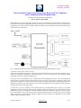
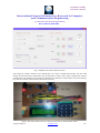
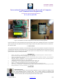
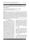
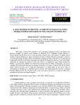
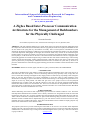
ISSN(Online): 2320-9801
ISSN (Print): 2320-9798
International Journal of Innovative Research in Computer
and Communication Engineering
(An ISO 3297: 2007 Certified Organization)
Vol. 2, Issue 4, April 2014
of the DISADV user’s station while figure 2 shows the ADV user’s monitoring and control interface. Following this is
the hardware and software implementation descriptions of this system. The author has selected to use the LPC2148 on
the DISADV user’s side since it has 2 UARTs, UART0 and UART1. This will enable the connection of both the zigbee
module and PC at the same time.
Fig. 1: The block architecture of the node to be monitored and controlled (The DISADV user node).
A. Hardware Description for LPC2148 station.
The hardware and software descriptions of the system will also illustrate how the system functions by analysis of how
each of the components contributes to system functionality. As can be seen from Fig.1, the following hardware
components are used to set up the monitored station:
1) LPC2148: This is the controller used to coordinate all activities happening at this node. It is a 32 bit ARM based
microcontroller. Its choice has mainly been influenced by the presence of two serial ports (UART0 and UART1) such
that one port communicates with the remote PIC microcontroller via zigbee and the other port communicates with PC’s
Graphical user interface. The microcontroller receives control instructions and query commands via both serial ports
and responds to give the status of the system.
2) LM35 Sensor: This is a temperature sensor which checks the room temperature. When system is in auto mode
temperature set points are defined (maximum and minimum temperature) and the fan can be switched ON and OFF
automatically if set points are exceeded. In manual mode the LM35 checks temperature value upon a request to know
the room temperature. Also in this mode the fan is switched ON/OFF by the users. The LM35 gives out an analogue
value, so the sensor is connected to the Analogue to Digital Conversion channel. The configuration of ADC module
and data capture is illustrated in Table 1.
Copyright to IJIRCCE
www.ijircce.com
3867